

Micron Electronics TransPort TREK 2 AGP User Manual

1
TREK 2 AGP
User’s Guide
(C )Copyright 1998
All Rights Reserved.
Manual edition January 1999
Document Number G790
The information in this document is subject to change without prior
notice in order to improve reliability, design and function and does not
represent a commitment on the part of the manufacturer.
In no event will the manufacturer be liable for direct, indirect, special,
incidental, or consequential damages arising out of the use or inability to
use the product or documentation, even if advised of the possibility of
such damages.
This document contains proprietary information protected by copyright.
All rights are reserved. No part of this manual may be reproduced by
any mechanical, electronic, or other means in any form without prior
written permission of the manufacturer.
Trademarks
Phoenix is a trademark of Phoenix Technologies Ltd. CardSoft is a
trademark of SystemSoft Corporation. AutoCAD and Autoshade are
trademarks of Autodesk, Inc. IBM, OS/2, and VGA are trademarks of
International Business Machines Corp. Lotus, 1-2-3, and Symphony are
trademarks of Lotus Development Corp. Windows, Word, MS-DOS, and
Microsoft are trademarks of Microsoft Corp. VESA is a trademark of Video
Electronics Standards Association.
Other product names mentioned herein are used for identification
purposes only and may be trademarks and/or registered trademarks of
their respective companies.
Limitation of Liability
While reasonable efforts have been made to ensure the accuracy of this
manual, the manufacturer and distributor assume no liability resulting
from errors or omissions in this manual, or from the use of the information
contained herein.
MAS001571-02 2/99
(TREK2 AGP)
EHW / MJB

2
From the Editors . . .
This may your first time setting up your computer, in which
case, it is hoped that this manual will be an effective resource
for you to make this as much of a learning process, and as less
of a hassle, as possible.
There exists the possibility that you have already set up your
machine, and you’ve taken the manual out for a detailed look
at your system’s features. You may want to know about
possible configuration changes and modifications that can be
made, or simply match wits with the glossary and see if you
can come up with the correct definition for “BIOS” without
peeking.
Another reality is one of frustration, hair-pulling and possible
cursing. The possibility of “something isn’t working right.”
Reconfiguring the CMOS screens may have seemed like a
good idea at the time, but now you are only getting cranky
beeps. Now what?! You may be trying to get help online …
but a blank screen isn’t going to help you out much there, and
you’ve pulled the guide out as a last resort.
Fair enough.
If the reason you got the user’s guide out is based on the last
possibility … first things, first … take a deep breath.
The system user’s guide is designed to help you in all of the
above situations, and give you a ready reference to the
capabilities of your system.
A troubleshooting section may save you a call to technical
support, should you be staring at a blank screen right now.
We want to make this guide as useful as possible and
welcome your comments. You can send comments to:
manuals@micronpc.com.
Whatever reason brought you to reading the user’s guide …
Welcome. We hope it makes your experience with Micron
even better.
Sincerely,
The editors

3
Contents
Trek 2 User’s Guide
Trademarks ................................................................................................... 1
Safety precautions ....................................................................................... 2
From the editors ............................................................................................ 2
About this manual ....................................................................................... 5
Personal inventory ........................................................................................ 6
1. Getting started.....................................................10
Unpacking the TREK2......................................................................11
Keep the box......................................................................................11
Let your computer acclimate itself...................................................11
Heat, cold, humidity, and glare .....................................................11
Surge suppressors ...................................................................................... 1 1
Where to work....................................................................................11
System features ..........................................................................................1 2
Accessories and optional devices ...........................................................1 4
Preparing your TREK 2 for transport .................................................... 1 4
Opening the LCD panel ............................................................................ 1 5
Front left view ............................................................................................. 1 5
LCD cover release hatch....................................................................15
XGA LCD screen................................................................................16
System status indicator panel...........................................................16
Keyboard............................................................................................17
Right view..........................................................................................19
Rear view............................................................................................20
Bottom view ................................................................................................2 1
Operating environment ............................................................................. 22
Connecting to power source ..................................................................... 2 2
Connecting AC adapter ........................................................................... 2 3
Turning on your computer ....................................................................... 2 3
About the ROM BIOS ............................................................................... 2 4
About the BIOS setup ............................................................................... 2 4
About the Power-On Self Test ................................................................ 2 4
Charging the battery pack ........................................................................ 2 6
Ergonomics ..................................................................................................2 6
2. Caring for your Trek 2.......................................27
Preventing problems.............................................................................27
Safety instruct ions ..................................................................................... 2 8
Power ............................................................................................................2 8
Battery .......................................................................................................... 2 8
Traveling with your computer ............................................................... 2 8
Batteries and battery discharge ............................................................... 2 9
Taking care of the LCD screen ................................................................ 2 9
Satety precauations ...................................................................................3 0
Optional port replicator safety ...............................................................3 1
3. T roubleshooting................................................ 32
Locating a problem .................................................................................... 3 2
Checking cables and connections ............................................................ 3 2
Power-On Self Test .................................................................................... 33
General hardware problems ..................................................................... 3 4
Contacting technical support .................................................................. 3 4
4. Using the TREK 2..............................................35
Operating the TREK 2.......................................................................35
The LCD display ........................................................................................ 3 5
External CRT display ................................................................................3 5
Tour of the
TREK 2 keyboard ................................................................. 3 6
System status window icons ................................................................... 3 8
Touch pad .................................................................................................... 3 9
Data storage and retrieval ........................................................................ 4 0
Floppy disk drive ....................................................................................... 40
Removing the floppy disk drive .............................................................. 4 1
Caring for diskettes...........................................................................42
Removable hard disk drive module..................................................42
CD-ROM ...................................................................................................... 4 4
Precautions for handling CD-ROM disks.........................................45
Loading a disc...................................................................................46
Reading CDs......................................................................................46
Multimedia sound system .......................................................................4 7
Audio volume control ............................................................................... 4 7
IR communication ...................................................................................... 4 7
PMCIA cards and expansion sockets .................................................... 4 9
Adding / upgrading system memory .............................................50
About power saving modes ..................................................................... 5 1
The AC adapter .......................................................................................... 5 1
The battery power system ........................................................................ 5 1
Power management summary..........................................................56
The APM interface.............................................................................57
5. Connecting peripheral devices.......................58
External keyboard/numeric keyboard ..................................................5 8
The legend bar .................................................................................................
Serial devices ............................................................................................... 5 9
Audio sources and output devices ........................................................ 6 0
Port replicator .............................................................................................6 0
USB device ................................................................................................... 6 0
TV Ou t .......................................................................................................... 6 1
Installing optional devices ........................................................................ 6 1

4
6. Optional fax/modem...........................................62
Installation ...................................................................................................62
Executing commands ................................................................................ 6 3
Basic AT commands .................................................................................6 3
Troubleshooting .......................................................................................... 6 7
Service and support ................................................................................... 6 8
7. Optional port replicator ......................................69
Operating environment ............................................................................. 69
Features ........................................................................................................7 0
Getting to know the port replicator ........................................................ 7 0
Left panel .....................................................................................................7 1
Right panel ................................................................................................... 7 1
Operation .....................................................................................................7 2
Connecting the notebook computer ....................................................... 7 2
Cold dock ..................................................................................................... 7 3
Removing PC cards .................................................................................... 7 3
8. Running BIOS setup..........................................77
Navigating through BIOS ......................................................................... 7 7
Launching submenus ................................................................................7 7
Saving changes ............................................................................................ 7 8
Main menu ................................................................................................... 7 9
Advanced menu .........................................................................................8 2
Power menu ................................................................................................. 8 5
Boot menu .................................................................................................... 8 9
Exit menu ..................................................................................................... 8 9
9. Software utilities..................................................92
MCRC............................................................................................................92
VGA Utilities ............................................................................................... 9 3
10. D VD setup...........................................................96
Installation and setup ............................................................................... 9 6
Removing CD-ROM drive ........................................................................ 97
11. Using PHDisk Utility........................................98
Command line options .............................................................................. 9 8
Help screen ................................................................................................... 9 8
CREATE option .......................................................................................... 9 8
REFORMAT option ....................................................................................9 9
INFO option ................................................................................................9 9
PHDISK Sign-On ..................................................................................... 1 00
Unrecognized option .............................................................................. 10 0
Fatal error .................................................................................................. 1 00
Save to Disk partition ............................................................................ 10 1
First two sectors bad ............................................................................. 10 1
PHDISK/CREATE failed to execute .................................................. 10 1
Appendices ...........................................................102
Appendix A: Specifications ........................................................................... 1 02
Appendix B: Index ........................................................................................... 1 06
Appendix C: Abbreviations .......................................................................... 1 09

5
About this manual
This manual contains information to help you get the most
from your TREK 2 computer. Whether you are a new or
experienced computer user , you will benefit more from this
manual if you are familiar with its organization. This manual
contains eleven chapters, appendices, and an index.
Chapter 1: Getting started
This section lists the special features of your TREK 2
computer and available options . And, w e’ll describe the parts
you should have received and give you step-by-step
procedures for setting up and starting the computer
Chapter 2: Caring for your TREK 2
Learn all of the ways to care for your TREK 2, to ensure years
or reliability and peak performance.
Chapter 3: Troubleshooting
Having a problem with y our TREK 2? Here’s a simple guide to
common troubleshooting techniques.
Chapter 4: Using the TREK 2
This chapter outlines the features and capabilities of your
TREK 2, and how to use those features for great performance.
Chapter 5: Connecting peripheral devices
We’ll show y ou how connect your TREK 2 to other systems
for advanced audio and visual enhancement.
Chapter 6: Optional fax/modem
This section provides an overview to the optional fax/modem
feature for the TREK 2.
Chapter 7: Optional port replicator
This section describes the optional port replicator for the
TREK2.
Chapter 8: Running BIOS setup
We’ll show you how to operate the Setup Utility that’s
provided in the computer’ s ROM BIOS .
Chapter 9: Software Utilities
Learn to install and use the software utilities and drives that
come with your computer .
Chapter 10: DVD Feature
We’ll sho w you the capabilities and how the use the TREK 2’s
DVD f eature .
Chapter 11: Using the PHDisk Utility
This chapter describes the suspend to disk date file allocation
utility to create the Suspend to Disk data file.
Appendix A: Specifications
Appendix B: Index
Appendix C: Abbreviations
In addition to this manual, you will also want to consult the
manuals for your operating system and application software.
Manual Conventions
The following conventions are used throughout this manual:
q Bullets (for example, this one) present lists of
information or items in a list of alternatives.
Numbered procedures guide you through sequential steps.
Notes contain important information that is set off from
the text. Caution messages appear before procedures
which, if not observed, could result in loss of data or
damage to equipment.

6
Personal Inventory
This TREK 2 computer system is designed for years of
productive and pleasurable computing. Use this section to
keep notes about details of your purchase. Update this
section when you add new options.
Date of Purchase:
Phone:
1-800-393-8935
Address:
E-mail address:
Transport.support@micronpc.com
Web site:
www.micr onpc.com
Type of LCD screen display
r 12.1” TFT SVGA Color LCD
r 14.1" Color TFT XGA LCD
r Others:
Serial Number:
CPU type:
Hard disk capacity:
Memory capacity:
Regulatory information
Compliance Information Statement
Declaration of Conformity
Responsible Party Name: Micron Electronics, Inc.
Address: 900 East Karcher Road
Nampa ID 83687
USA
T elephone 208/898-3434
Fax 208/898-3424
Type of equipment Personal computer
Model name: T ransPort TREK 2 AGP
TREK 2
Federal Communications Commission Radio
F requency Interference Statement
Note: This equipment has been tested and found to comply with
the limits for a Class B digital device, pursuant to Part 15 of the
FCC Rules. These limits are designed to provide reasonable
protection against harmful interference in a residential
installation. This equipment generates, uses, and can radiate radio
frequency energy and if not installed and used in accordance with
the instruction manual may cause harmful interference to radio
communications. However, there is no guarantee that interference
will not occur in a particular installation. If this equipment does
cause harmful interference to radio or television reception, which
can be determined by turning the equipment off and on, the user
is encouraged to try to correct the interference by one or more of
the following measures:
r Reorient or relocate the receiving antenna.
r Increase the separation between the equipment and
receiver.
r Connect the equipment into an outlet on a circuit
different from that to which the receiver is
connected.
r Consult the dealer or an experienced radio TV
technician for help.

7
Notice:
1. Changes or modifications not expressly approved
by the party responsible for compliance could void
the user’s authority to operate the equipment.
2. Shielded interface cables and a non-shielded AC
power cord must be used in order to comply with
emission limits.
3. This equipment is to be used with power supply:
ILAN F1700C (08), Delta ADP-50GB, or Delta ADP-
50PB Internal power supply.
Canadian DOC Notice For Class B Computing
Devices
This Class B digital apparatus meets all requirements of the
Canadian Interference - Causing Equipment Regulations.
Optional Port Replicator
Compliance Information Statement
Declaration of Conformity
According to FCC Part 15
Responsible Party Name: Micron Electronics, Inc.
Address: 900 East Karcher Road
Nampa ID 83687
USA
Telephone 208/898-3434
Fax 208/898-3424
Type of equipment Port replicator
1. The changes or modification not expressly approved
by the party responsible for compliance could void
the user’s authority to operate the equipment.
2. Shielded interface cables and a non-shielded AC
power cord must be used in order to comply with
emission limits.
3. This equipment should be used with power supply,
namely:
DELTE ADP-50GB or ADP-50MB; ILAN F1700C;
AMBIT APA-50XX.
Canadian DOC Notice For Class B Computing
Devices
This digital apparatus does not exceed the Class B limits for
radio noise emissions from digital apparatus set out in the
Radio Interference Regulation of the Canadian Department of
Communications.

8
Optional fax/modem
FCC Compliance
This equipment complies with Part 68 of the FCC Rules. On
this equipment is a label that contains, among other
information, the FCC registration number and Ringer
Equivalence Number (REN) for this equipment. You must,
upon request, provide this information to your telephone
company.
If your telephone equipment causes harm to the telephone
network, the Telephone Company may discontinue your
service temporarily. If possible, they will notify in advance.
But, if advance notice is not practical, you will be notified as
soon as possible. You will be informed of your right to file a
complaint with the FCC.
Your telephone company may make changes in its facilities,
equipment, operations, or procedures that could affect proper
operation of your equipment. If they do, you will be notified
in advance to give you an opportunity to maintain
uninterrupted telephone service.
The FCC prohibits this equipment to be connected to party
lines or coin-telephone service.
In the event that this equipment should fail to operate
properly, disconnect the equipment from the phone line to
determine if it is causing the problem. If the problem is with
the equipment, discontinue use and contact your dealer or
vendor.
The FCC also requires the transmitter of a FAX transmission
be properly identified (per FCC Rules Part 68, Sec. 68.381 ( c)
(3)).
FCC Class B Statement
This equipment has been tested and found to comply with the
limits for a Class B digital device, pursuant to Part 15 of the
FCC Rules. These limits are designed to provide reasonable
protection against harmful interference in a residential
installation. This equipment generates, uses and can radiate
radio frequency energy, and if not installed and used in
accordance with the instructions, may cause harmful
interference to radio communications.
However, there is no guarantee that interference will not
occur in a particular installation. If this equipment does
cause harmful interference to radio or television reception,
which can be determined by turning the equipment off and
on, the user is encouraged to try to correct the interference by
one or more of the following measures:
r Reorient or relocate the receiving antenna
r Increase the separation between the equipment and
the receiver
r Connect the equipment into an outlet on a circuit
different from that to which the receiver is connected
r Consult the dealer or an experienced radio/TV
technician for help
Notice:
1) Shielded cables, if any, must be used in order to comply
with the emission limits. 2) Any change or modification not
expressly approved by the Grantee of the equipment
authorization could void the user authority to operate the
equipment
DOC Compliance Information
NOTICE: The Canadian Department of Communications label
identifies certified equipment. This certification means that
the equipment meets certain telecommunications network
protective, operational and safety requirements. The
Department does not guarantee the equipment will operate to
the user satisfaction.

9
Before installing this equipment, users ensure that it is
permissible to be connected to the facilities of the local
telecommunications company. The equipment must also be
installed using an acceptable method of connection.
The customer should be aware that compliance with the
above conditions may not prevent degradation of service in
some situations.
Repairs to certified equipment should be made by an
authorized Canadian maintenance facility designated by the
supplier.
Any repairs or alterations made by the user to this equipment,
or equipment malfunctions, may give the telecommunications
company cause to request the user to disconnect the
equipment.
Users should ensure for their own protection that the
electrical ground connections of the power utility, telephone
lines and internal metallic water pipe system, if present, are
connected together. This precaution may be particularly
important in rural areas.
CAUTION: Users should not attempt to make such
connections themselves, but should contact the appropriate
electric inspection authority, or electrician, as appropriate.
NOTICE: The Load Number (LN) assigned to each terminal
device denotes the percentage of the total load to e connected
to a telephone loop which is used by the device, to prevent
overloading. The termination on a loop may consist of any
combination of devices subject only to the requirement that the
sum of the Load Numbers of all the devices does not exceed
100.
UL Notice
Caution: This internal modem adapter is to be installed in UL
listed computers only, Always disconnect the modem adapter
from the telephone system during installation or when the
cover is removed from the computer.
Ringer Equivalence Number
The ringer equivalence number of this modem is 1.
REN is a guide to the maximum number of apparatus that can
be simultaneously connected to one telephone line. The REN
value of each apparatus is added together, and should not
exceed 4. Unless otherwise marked, a telephone can be
assumed to have a REN of 1.
Approved Usage
This modem is only approved for use of the following
facilities:
Storage of telephone numbers for retrieval by a predetermined
code.
r Detection of initial proceed indication
r Automatic calling/Automatic answering
r Tone detection
r Operation in the absence of secondary proceed
payphone
r Loudspeaking facility
This modem is NOT suitable for use as an extension to a
payphone.
This modem is not approved for connection to private
speechband services. This modem does not support
automatic redial function.
Any other usage will invalidate the approval of your modem,
if, as a result, it then ceases to conform to the standards
against which approval was granted.
10
1. Getting Started
Congratulations on y our purchase of the TransPort TREK 2.
Your TREK 2 features the latest advances in portable
computing technology . The TREK 2’s modular design
provides maximum expandability — without compromising
portability . The high-performance Pentium II CPU and
enhanced IDE hard drive provide you with extra processing
power for handling complex graphics and running large
programs.
Two PCMCIA slots give you the ability to use standard
PCMCIA cards, such as a LAN adapter or memory cards.
The TREK also features tw o e xpansion module bays. The
first accommodates an FDD .
The second expansion module bay accommodates a 5¼” CDROM drive, DVD-ROM or a second HDD. The TREK’ s
state-of-the-art ergonomic design and sophisticated
architecture provides you with a portable personal computer
that is compact, powerful, and easy to use.
To keep pace with the accelerated advances in technology ,
your TREK 2 provides e xtensive upgr ade options, including a
removable hard disk drive, PC cards (including an
MPEG 2
card, an optional port replicator, and memory expansion
cards.)
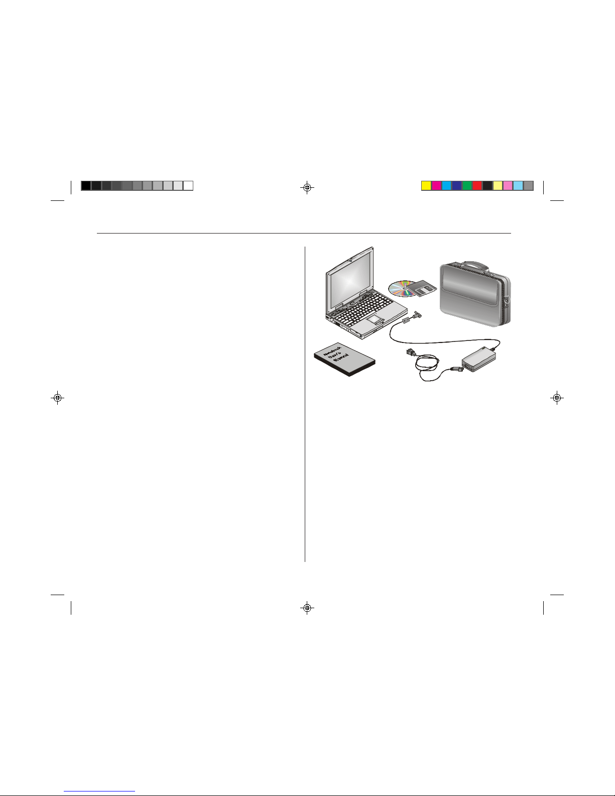
Figure 1-1: The TREK 2 and accessories
This User’s Guide describes all f eatures of the Tr ansP ort
TREK 2 in an easy-to-read yet thorough manner . The primary
goals of this chapter are to identify the TREK 2 external
components and to provide a quick reference of functions for
experienced computer users.

11
Unpacking the TREK 2
The TREK 2 comes securely pac kaged in a sturdy shipping
carton. Upon receiving your TREK 2, open the box and
carefully remove the contents. If anything is missing or
damaged, please contact Micron Electronics immediately. All
systems should include the following items:
q The TREK 2 computer
q An AC adapter
q An AC power cord
q A smart lithium-ion battery pack
q Software and Micron Customer Resource Center CD
q User’s manual
This book shows you how to set up your system and keep it
running.
Keep the box
It’s a good idea to keep your TREK 2’s box and packing
materials. That way, if you ever have to store the system or
return it, your components will be well protected
Let your computer acclimate itself
Although your TREK 2 can easily stand temperature
extremes, it doesn’t like
rapid
changes in temperature, like
going from the cold outdoors to a warm office. Rapid changes
in temperature can cause water droplets to condense inside
your case, threatening to damage the electronic parts inside.
If it’s hot or cold outside when you receive your system, let
the computer gradually adjust to room temperature for three to
four hours before you power it up.
Caution!
If your system arrives in cold weather , do not apply pow er to
the computer or monitor until they have been allowed to
come to room temperature.
Heat, cold, humidity , and glare
Find a spot for your computer that’s not too hot, too cold, too
dark, or too bright. Glare can make it hard to read the screen.
Overheating can destroy computer components, so allow
plenty of room for air to circulate around the case. Do not
place your TREK 2 in direct sunlight.
Surge suppressors
Your computer has its own electrical filters, fuses, and
protections, and ev en its own b uilt-in surge suppressor .
Also, we strongly recommend using a high-quality, external
surge suppressor . An e xternal surge suppressor looks like an
extension cord with several grounded outlets. It will shield
your computer from lightning strikes, surges, shorts and other
electrical hazards.
Where to work
Your TREK 2 generally will run well where v er you’ re
comfortable. But extremes of temperature and humidity can
be challenging to your system’s parts.
There are, howe ver, some things you can tolerate that the
computer can’t — things like static electricity, dust, water,
steam, and oil. So, whenever you decide to pull over for
roadside computing, choose a clean, comfortable work area
for your system.
When traveling, your system operates on an intelligent
lithium-ion battery pack. Before you run your system for the
first time on battery power, remove the battery from its
package and install it in the system. Then recharge the
battery fully to prepare the battery pack for maximum service.
Caution!
Except for PC cards, never connect or disconnect any
equipment or components while the system power is on.

12
Display
The LCD assembly comes with either of the following display
options:
q 12.1" TFT SV GA, 800 x 600 x 64K color resolution
q 14.1" TFT XGA, 1024 x 768 x 64K color resolution
VGA graphics accelerator
The video subsystem includes 4MB of SGRAM video
memory, a 3D g raphics engine, and a high perf ormance 32-bit
PCI Bus with support for full power management. The video
subsystem supports a ZV (Zoomed Video) port and
simultaneous display (Simulscan) in all video modes.
System features
This section provides an ov erview of the TREK 2’s features.
For more detailed information see the Specifications section
in Appendix B.
Central processing unit (CPU)
The microprocessor (CPU) is the key hardware
feature; it is the brain of the computer , performing all the
computing functions and orchestrating the actions of the
system.
The T ransP ort TREK 2 supports the Intel Pentium II processor
at clock speeds up to 366MHz. All supported Intel
processors are availab le with MMX technology. The MMX
media enhancement technology was designed specifically for
faster processing of multimedia and communications tasks.
The TREK 2 also employs the Intel 440BX core logic.
L2 cache
The TREK 2 supports a 512KB L2 write back cache with
synchronous pipeline burst mode, or 256kb of full bus speed
on-die L2 write back cache with synchronous pipeline burst
mode (333 and 366 MHz models only) . The e xternal cache
enhances system performance, especially in the Window s
environment.
Upgradeable system memory
The TREK 2 has a 64-bit memory bus. Memory can be
upgraded to 256MB by the following options:
q One or two 32, 64, or 128MB 144-pin, 3.3V,
SDRAM SO-DIMM modules.
Removable hard disk drive module
The TREK 2 comes with a 2.5" (12.7mm maximum height)
hard disk installed. The HDD supports PIO mode 4. The hard
drive can also be easily removed and replaced with a second
hard drive f or e xpansion. The TREK 2 supports HDDs with
capacities of 1.44GB or above, and supports Ultra DMA/33
transfers allowing data transfer rates up to 33 MB per second.
Removable CD-ROM
The high speed built-in CD-ROM drive allows you to take
advantage of the wide array of multimedia titles available, and
can be swapped with a Digital V ersatile Disk (DVD) ROM
drive, or a second HDD .
Pointing device
The touch pad is a pressure-sensitive pointing device. It
allows you to move the cursor around the screen and make
selections just as with a conventional mouse.

13
Windows 95 enhanced keyboard
The TREK 2 keyboard uses a standard QWERTY la yout with
the addition of special function keys and an embedded
numeric keypad f or number intensiv e data entry. The TREK
2’s enhanced ke yboard design emulates a full-siz e desktop
keyboard and supports multiple language formats. Your
keyboard supports Windows 95 b y incorporating two Windows
specific keys. With the two Windows 95 keys you will be able
to access and take advantage of the many time-saving
features of Windows 95 software.
PCMCIA interface
Two PCMCIA expansion sockets provide an interface for 2
Type II cards, or 1 Type III card (with CardBus support). Your
TREK 2’s PCMCIA interface supports multi-function (combo)
cards and Zoomed Video . The PCMCIA system can accept
either 3 or 5 volt cards. PC cards accommodate a number of
expansion options, including memory cards, modems, hard
disks, and network adapters.
Serial port
The TREK 2 has a standard 9-pin RS-232 serial port (16550
compatible) that you can use for connecting serial devices.
Parallel port
The TREK 2 has a 25-pin parallel port which is most
commonly used to connect a printer or Pock et LAN to the
computer. The par allel port supports both EPP and ECP
capabilities.
IR (Infrared) communication port
The TREK 2 f eatures an IrD A compatib le F ast Infrared (FIR)
communication module. The FIR module enables you to
make serial communication between the TREK 2 and other IR
equipped devices such as a printer or another TREK 2
computer.
USB port
Two USB (Universal Serial Bus) connectors are available for
you to connect USB devices. The USB is a personal
computer bus endorsed by Intel and others that has a total
bandwidth of 1.5-12MB per second, making it much faster
than conventional serial ports.
Audio system
The TREK 2’s audio system includes a sophisticated built-in
ESS PCI stereo audio-sound generator compatible with Sound
Blaster and Microsoft Sound System. The sound system
includes amplified output, two built-in, 1 watt stereo speakers,
manual volume control and built-in microphone.
Audio ports
The TREK 2 comes with f our audio jacks: a line in for
connecting audio equipment for use with the multimedia
system; and a line out for connecting stereo speakers, a
headphones jack, and a microphone jack.
External keyboard or PS/2 mouse port
The TREK 2 has a 6-pin connector for connecting a full-size
keyboard or a PS/2 mouse.
VGA port
At the rear of the TREK 2, there is a 15-pin VGA connector for
connecting an external CRT monitor .
TV Out port
This S-video port allows you to view the TREK 2’s LCD panel
output on a television monitor .
Keyboard controls
The TREK 2 provides a host of hot key features that are a
permanent part of the computer’ s oper ation. Some aff ect the
LCD video display , while others control po wer management.

14
Battery and AC power system
The TREK 2 can operate on two power sources; an AC
adapter, or the rechargeable battery module pack.
The AC adapter has automatic 100-240V line switching which
will automatically check the power voltage coming out of the
wall and adjust it to the voltage your computer requires.
The system will automatically recharge the battery pack in the
TREK 2 by using the A C adapter. By using the power
management features described in using the TREK 2 and
BIOS setup chapters, the TREK 2 can operate on battery
power for approximately two to three hours. For extended
battery-powered operation, additional battery modules may be
purchased.
Security
The password protection feature of y our TREK 2 can prevent
unauthorized people from accessing important files and
information on your computer
Note:
Because the TREK 2 computer is available in different
configurations, some of the features mentioned in this manual
might not be included on your computer or may differ slightly.
Accessories and optional devices
To further enhance the utility of your TREK 2 computer, there
are several accessories and optional products available.
r SO-DIMM 3.3V SDRAM modules
(32MB/64MB/128MB modules)
r Port replicator with two type II PCMCIA slots
r 2nd HDD module
r DVD-ROM dri v e
r Internal V .90 56K fax/modem module
r MPEG2 video decompression module
Preparing the TREK 2 for transport
To prepare the computer for transport, you should first
disconnect all peripherals. Make sure the computer is turned
off before you do this. After disconnecting all peripherals,
close the rear port covers to protect the connectors.
The TREK 2’s hard disk head is self-parking. This means
that the TREK 2 can be directly turned off from the DOS
prompt. Close the LCD panel and check that it is latched
securely to the computer . Make sure the floppy drive does
not contain a diskette. When a diskette is inserted in the
floppy drive the eject button pops out. If you attempt to
transport the TREK 2 with a diskette in the drive, you risk
damaging the eject button.
The computer has an optional soft carrying case. It will keep
out dirt and dust and protect your TREK 2’s casing from
becoming scratched or cracked.
If you intend to use battery power , be sure to fully charge the
battery pack and any spares. Remember the adapter charges
the battery pack as long as it is plugged into the computer
and an AC power source.
15
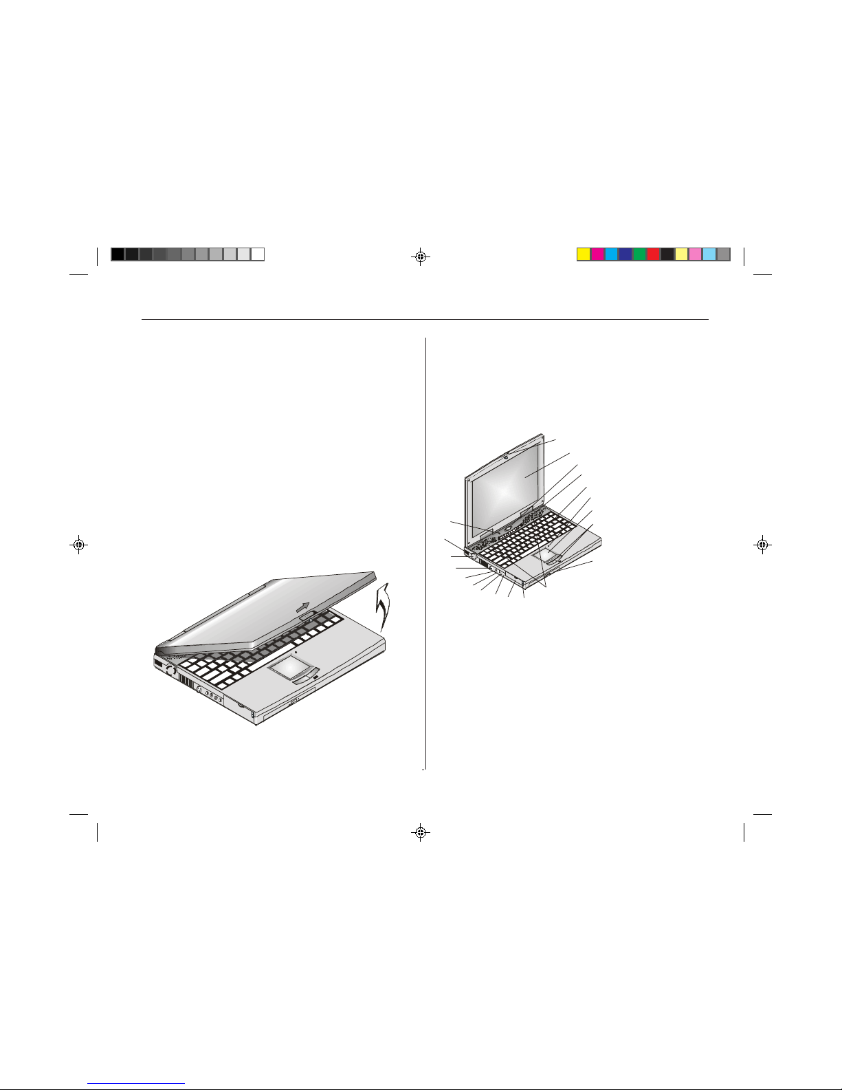
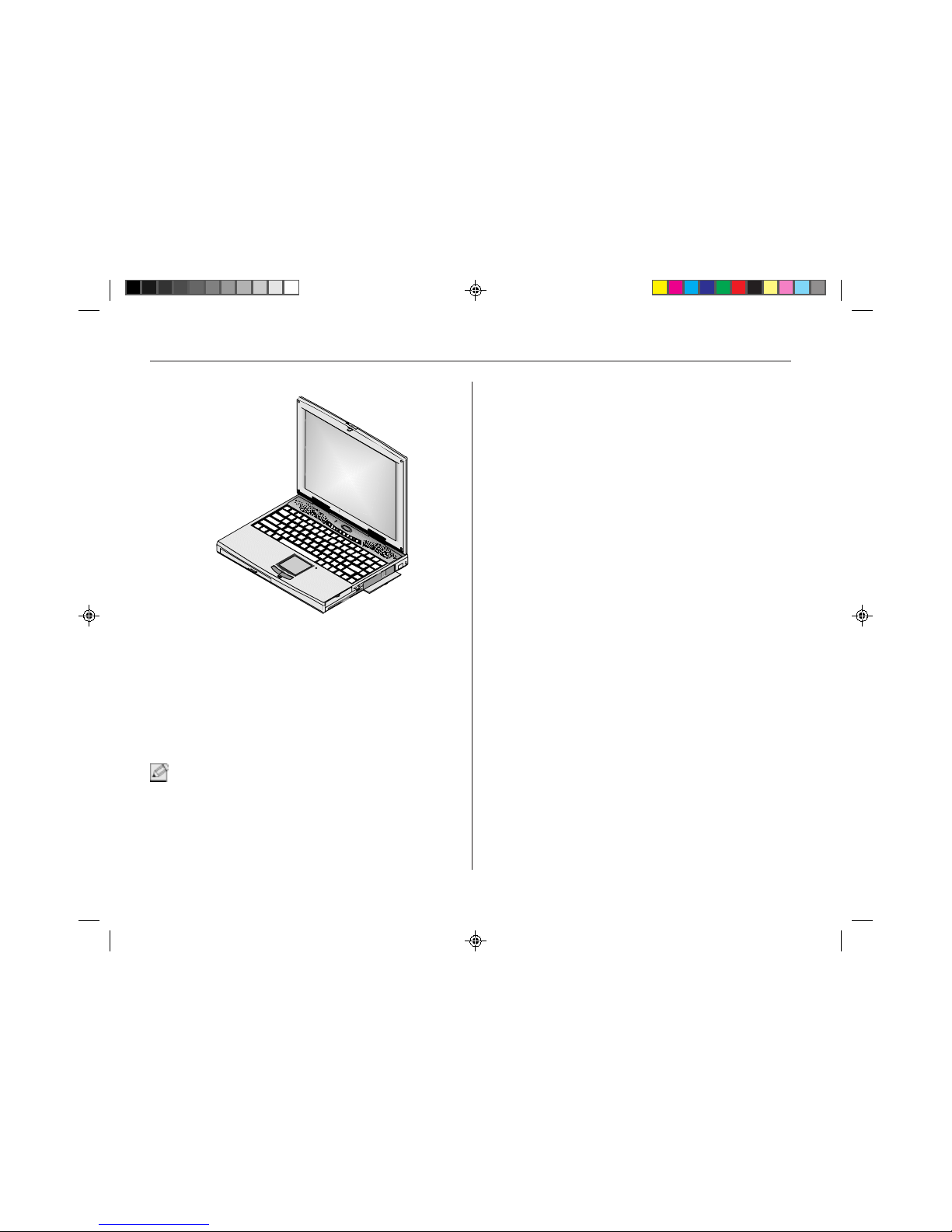
Opening the LCD panel
At the front of the TREK 2 you will find a retaining latch on the
display panel which locks the display in closed position when
the TREK 2 is not in use . Follow these steps to raise the LCD
display cover:
1. Locate the display panel latch at the front of the LCD
panel.
2. Slide the display panel latch to the right until the
display panel releases, and then raise the LCD
screen.
3. Tilt the display to a comfortable viewing position.
Figure 1-2: Opening the LCD display cover
Front left view
With the LCD screen open, you will see several features
important for operating your TREK 2 computer.
1
2
3
4
5
6
7
8
9
10
11
12
13
14
15
16
17
18
19
20
Figure 1-3: The front left view
1. LCD cover release latch
Slide this latch to the right to open the LCD cover.
Your TREK 2 computer is equipped with a replaceable color
Liquid Crystal Display (LCD) screen. The LCD panel supports
1024 x 768 x 64K LCD resolution utilizing a PCI display
adapter. The LCD screen and XGA display circuitry let you
view text and the latest high resolution video images.
16
When you ha v e connected an e xternal monitor, the computer
lets you simultaneously view the LCD screen and the external
monitor . F or details on connecting an external monitor, see
Chapter Four.
3. Power/Suspend/Resume button
The button located at the top and center of the keyboard is
the power On/Off/Suspend/Resume button. Press and hold
the power button for four to six seconds to power the system
off. Pressing this button for one second, when the computer
is in Suspend mode, will resume normal operation.
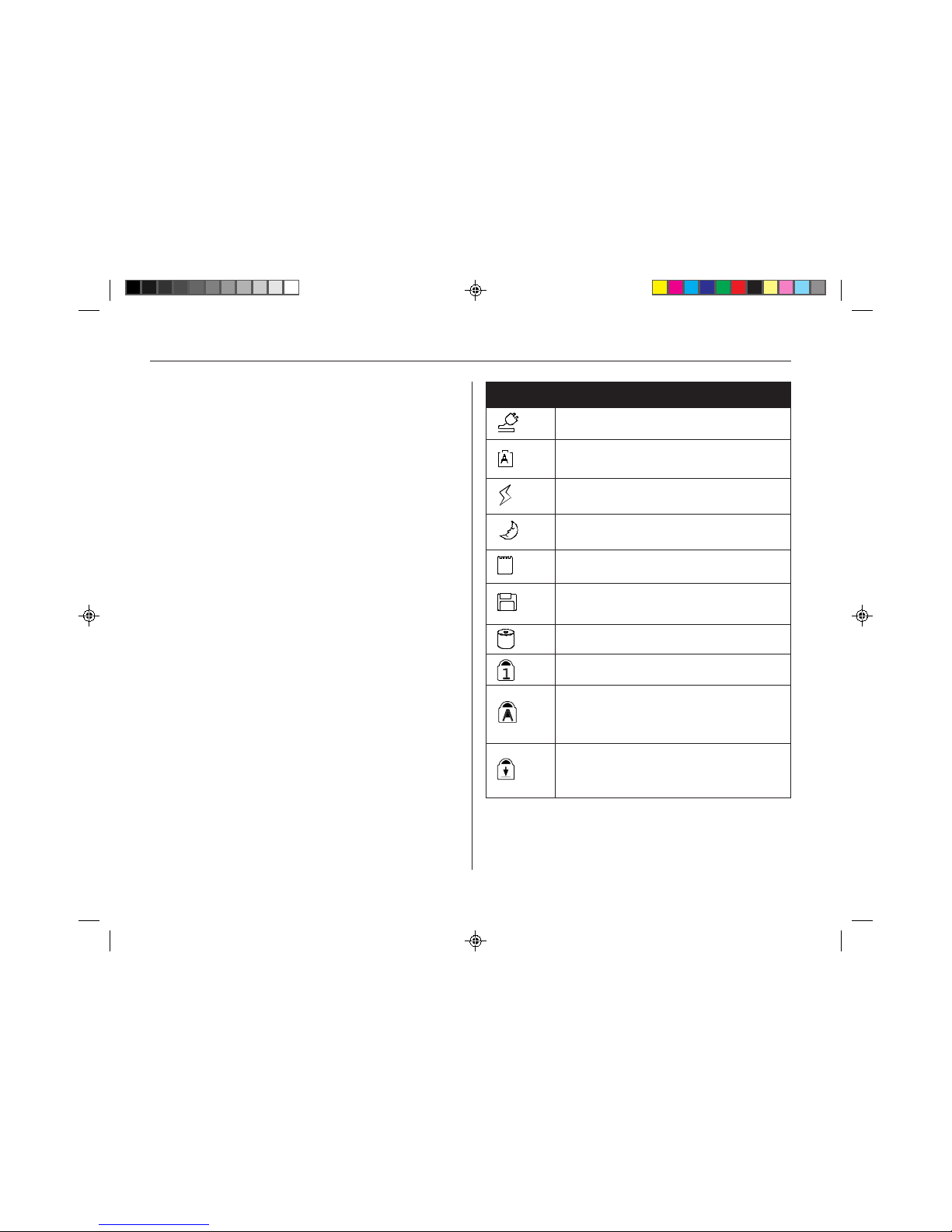
4. System status indicator panel
The system status indicator panel, located below the LCD
screen, keeps you inf ormed of the computer’ s operating
status. These icons are described below, from left to right.
There are also three system status indicators — power,
suspend, and battery charge — on the LCD cover.
Indicates AC adapter connected when lit
The A icon indicates the primary battery is being
charged (or discharged when the AC adapter is not
connected.
Orange indicates AC adapter is connected and battery
is charging. LED is green when battery is fully
charged.
Indicates TREK 2 is is Suspend mode when lit. See
Chapter 4 for more information on power modes.
Appears when computer is accessing PCMCIA slots.
See Chapter 4 for more information.
Appears when computer is accessing the floppy disk
drive. See Chapter 4 for more information
Indicates computer is accessing the hard disk drive.
Indicates keyboard is in Num Lock mode. See Chapter
4 for more information.
Indicates when the keyboard is in Cap Locks mode. In
this mode, the keyboard produces uppercase text
while you press a key. When you press it again, the
indicator turns off and the keyboard produces
lowercase text.
Indicates keyboard is in Scroll Locks mode. Some
applications will move information differently when
Scroll Lock is on.
Icon Description
2. Power/Suspend/Resume button
A built-in backlight allows y ou to comfortably view the screen
even when ambient lighting is low. You can also connect an
optional external VGA/SV GA color display monitor to the
external CRT connector on the rear panel of the computer .

17
5. Keyboard
Your computer has an 84-key enhanced keyboard which
provides all the functions of a standard 101/102 key keyboard.
The embedded numeric keypad allows easy number input.
The keyboard is the primary method of communicating with
the computer. You can use your ke yboard to enter text and
navigate through screen displays. Since you will be spending
much time at the keyboard, it is a good idea to familiarize
yourself with its lay out. The keyboard comes with an
ergonomic keyboard base to pro vide extra support for your
wrists while you are typing.
6. Built-in microphone
The built-in microphone is located to the right of the touch
pad.
7. Touch pad
The dual-button touch pad is located below the keyboard. The
touch pad is hardware-compatible with the IBM PS/2 mouse
and software-compatible with the Microsoft mouse.
Rest your finger or thumb on the pad. As you drag your finger
across the pad, the pointer follows your movement. For more
detailed information, see Chapter 4.
8. Touch pad buttons
The buttons below the touch pad correspond to the left and
right buttons on a standard mouse.
9. CD-ROM drive
Your TREK 2 comes with a swappable 20X (or faster) 5.25"
IDE CD-ROM drive. You’ll be able to reference vast amounts
of information, take advantage of multimedia programs, watch
video CDs, and listen to your favorite audio CDs while working
with other applications. The CD-R OM dri ve is s wappab le with
a Digital Versatile Disk (DVD) dri ve, and a second HDD.
10. Stereo speakers
The internal speakers are located directly below the LCD
panel on the left and right side of the TREK 2. These
speakers provide true stereo sound.
11. PCMCIA socket buttons
The computer has two PCMCIA connectors (two PCMCIA
type II connectors or one PCMCIA type III connector). T he
upper socket is PCMCIA socket “0”; the lower socket is
socket “1”. The upper ejection button is for sock et “0”, the
lower button is for socket “1”.
12. PCMCIA sockets cover
Open this cover to access the PCMCIA socke t s. The
computer’s PCMCIA sockets let you extend the capabilities of
your computer by inserting PC cards. The cards are hot
swappable, meaning you can change cards without having to
reboot your computer. There are a wide v ariety of PC cards
available, including data storage, fax/modem, Local Area
Network (LAN), wireless communication cards, and more. For
a detailed description of using PC cards, see Chapter 4.

18
13. External headphone jack
Connect stereo headphones to this jack to listen to the TREK
2’s audio output.
14. Line out jack
This is for speaker output. You can plug amplified external
speakers or headphones into the speaker output jack, or
connect the audio out jack to an audio device such as a
cassette recorder to record the TREK 2’s audio output. For
more information, see Chapter 4.
15. Line in jack
This jack is for auxiliary input. The auxiliary input can be
used to connect an external audio source (cassette player,
CD player , etc.) to y our TREK 2. With the proper software y o u
will be able to record this input signal.
16. External microphone jack
This mono microphone jack is used to connect an external
microphone.
17. External keyboard connector
You can connect an external keyboard, numeric keypad, or
IBM PS/2 compatible mouse to this socket, marked with the
keyboard/mouse icon.
This connector only accepts an external keyboard with a 6-pin
(PS/2-compatible) connector . To connect a keyboard with a 5pin connector, use a 5-pin to 6-pin transf er cable. You can
also connect an external IBM PS/2 compatible mouse into
this socket.
18. Cooling fan
This fan pre vents the TREK 2’s CPU and other internal
components from becoming overheated. Keep this fan
unobstructed to allow proper ventilation to the TREK 2’s
internal components.
19. Infrared data port
The Infrared Data Port allows your TREK 2 to become truly
wireless. You can use this port to transfer large amounts of
data very quickly to any other machine (TREK 2 computers,
printers, etc.) which is also equipped with an IrDA-compliant
IR port. This allows you to print documents without any
inconvenient cable hookups.
20. Cover close switch
When you close the LCD cover, this switch turns off the LCD
backlight.
19
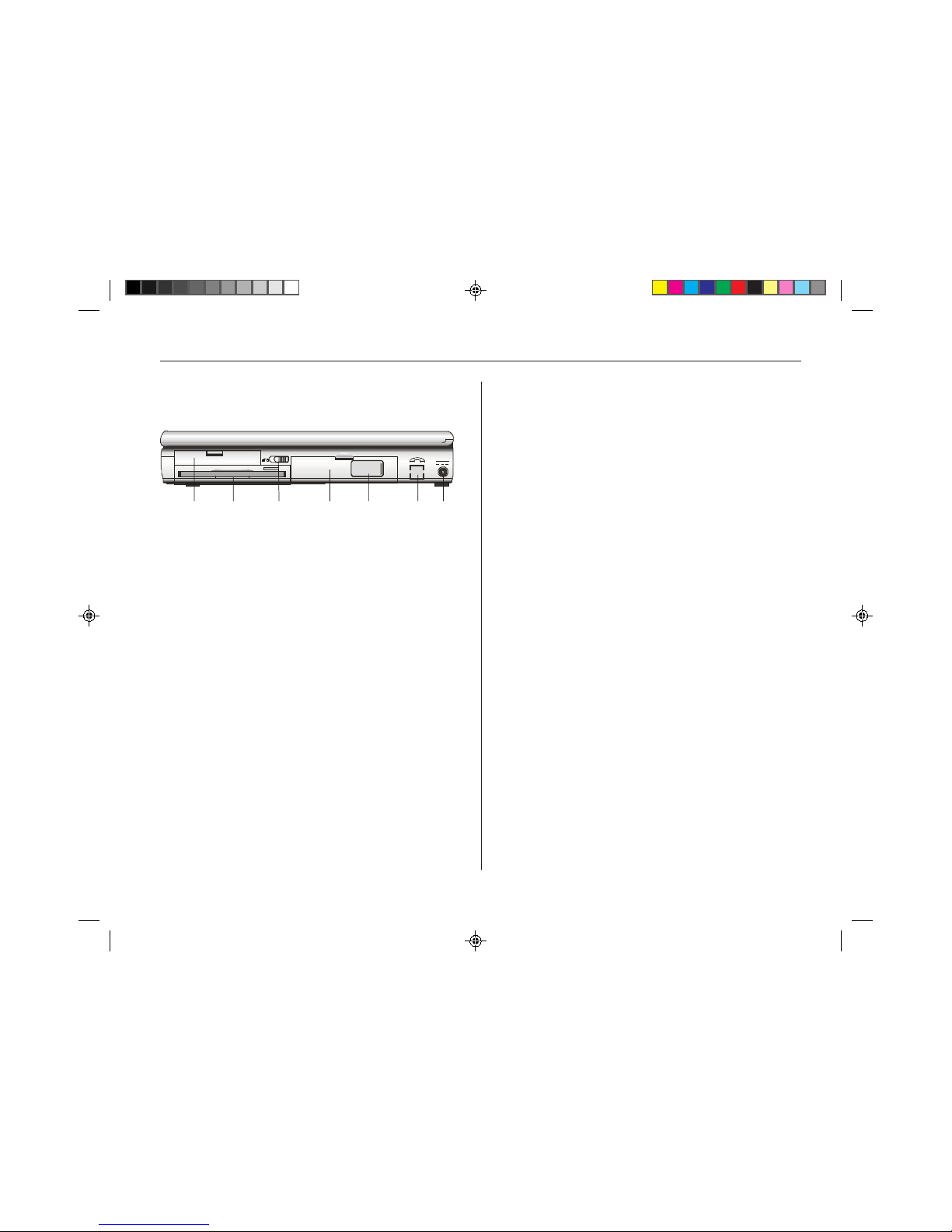
The right view
1. Removable hard disk drive
Your computer includes a removable 2.5-inch IDE hard disk
drive (12.7mm in height) with 1.44GB or more storage
capability. The TREK 2 PC’s BIOS automatically detects IDE
drive types. Consult your dealer for information on changing
your TREK 2’s HDD .
2. Floppy disk drive (FDD)
Your TREK 2 has a 3.5" floppy disk (FDD) installed. The FDD
is capable of reading and writing 3.5" 1.44MB floppy
diskettes. When the FDD is reading from or writing to a disk,
the FDD icon on the LED indicator panel will illuminate.
3. Battery lock
Slide the battery lock to the left when removing the battery
module from the battery bay.
4. Battery
Your TREK 2 comes equipped with a factory-installed battery
pack module. After the battery runs down, the module can be
removed and replaced with a charged battery . Additional
battery packs are optional.
5. N/A
6. Optional modem
If equipped, there will be an RJ11 connector for modem and
fax use.
7. DC IN connector
Plug the AC adapter into this connector . Refer to this
chapter, Connecting to a Power Source, for more information.
Figure 1-4: The right view
20
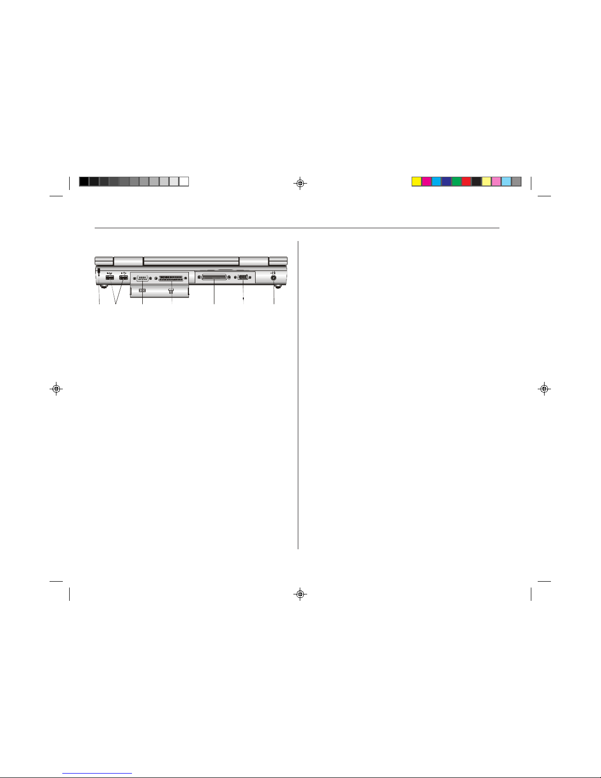
Rear view
Figure 1-5: The rear view
1. Kensington lock keyhole
Your computer includes a keyhole to be used with a standard
Kensington lock. You can connect the TREK 2 lock to a large
object with the Kensington loc k to prevent theft of your TREK
2. See the documentation that comes with your Kensington
lock for more information.
2. USB ports
Your computer includes two Universal Serial Bus (USB) ports.
USB is the latest development in Plug-and-Pla y technology.
It will eventually replace the need for separate connectors for
external keyboards, serial ports, and parallel (printer) ports.
With broad industry support, USB is sure to play an important
role in the design of future peripheral devices. As more and
more of these devices become available, your computer will
be ready to use them.
3. Serial port
This port is used to connect RS-232 serial devices to the
TREK 2. Three types of serial devices are; external mice,
serial printers, and fax/modems.
4. Parallel port
This port allows you to easily connect a parallel printer or
plotter using this 25-pin bi-directional female port.
5. P ort replicator connector
Connect the optional port replicator to the 204-pin port
replicator connector . This will further enhance your TREK 2’s
portability by making it easy for you to connect and
disconnect peripheral devices to your TREK 2.
6. External monitor port
This port allows you to easily connect an external VGA/SVGA
display monitor into your TREK 2 using the 15-pin female
connector.
7. TV out port
This 4-pin S-Video port allows you to view the TREK 2’s Video
output on a S-Video Capable tele vision monitor.
1 2 3 4 5 6 7
21
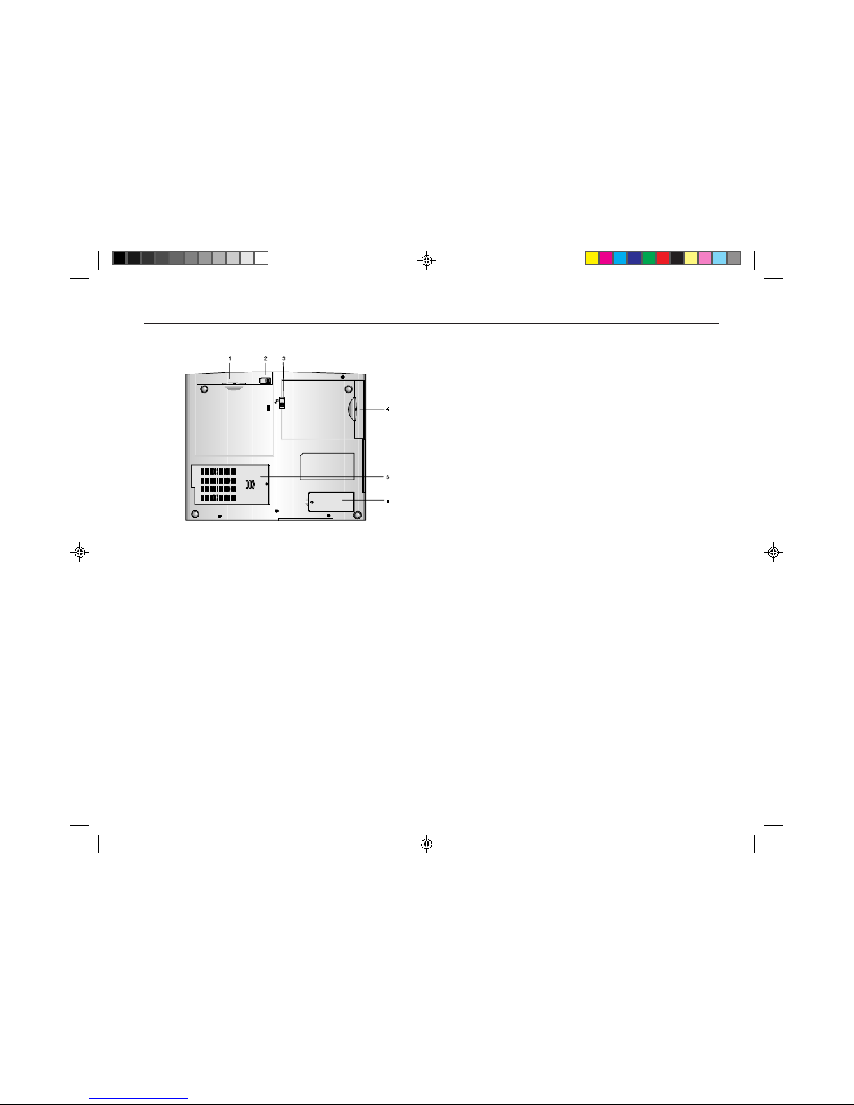
Bottom view
Figure 1-6: Bottom vie w of TREK 2
1. CD-ROM drive
The TREK 2’s CD-ROM drive can be remov ed and replaced
with a D VD-ROM drive, or second HDD.
2. CD-ROM release latch
Slide this latch to release the CD-ROM drive, DVD-ROM
drive, or second HDD from the CD-ROM bay.
3. FDD release latch
Slide this latch to release the FDD drive .
4. FDD drive
The TREK 2’s floppy disk drive is used for floppy disk date
storage and retrieval.
5. CPU cover
This covers the CPU compartment providing easy access to
allow for upgrades. Only experienced service technicians
should open this cover.
6. Future expansion compartment cover
This compartment houses an expansion MPEG-2 card or a
56K fax/modem.

22
Operating envir onment
You can use your computer under a wide range of
environmental conditions. How ev er, to ensure long use and
continued high performance, consider the following factors
when setting up your computer:
r Set the computer on a flat, stable surfac e. To prevent
damage to the computer’s hard disk drive, avoid using the
computer where it will be exposed to strong vibration.
r Place the computer away from electromagnetic or radio
frequency interference (for example, television/stereo
sets, copying machines, and air conditioners).
r A void using or storing the computer where it will be
exposed to e xtreme temperatures. In particular, do not
leave the computer in direct sunlight, over a radiator, or
near a heat source for a long period of time. High
temperature can damage the circuitry .
r A void e xposing the computer to high or low humidity.
Extreme humidity can contribute to disk drive failure.
r If y ou are using the computer with the AC adapter, do not
allow anything to rest on the power cord. Do not place the
computer where people can step on or trip over the
cord.
r The openings on the computer are provided to protect the
computer from overheating. To ensure reliable operation,
leave about 10 cm (4 inches) around the computer for
unobstructed air circulation. Av oid e xposing the computer
to dust or smoke.
Connecting to a power source
You can use the provided AC adapter to supply your computer
with power from an AC w all outlet. Your computer also comes
with a rechargeable battery pack that lets you use the
computer without an external power source.
Connecting the AC adapter
Use the provided universal AC adapter to supply your
computer with power from an AC wall outlet. You can also use
the AC adapter to charge the computer’s battery pack.
The AC adapter con verts high-level AC voltage to the much
lower le vel DC v oltage appropriate for the computer . The
adapter’s AC input v oltage can range anywhere from 100 to
240 volts, covering the standard voltages available in almost
every country .
The power cord for the AC adapter requires a two-hole
grounded AC outlet. An optional four- or six-plug power strip
is a convenient addition, especially if you have only one wall
plug and several devices that need electricity. You can buy
power strips with built-in electrical surge protection. This
provides limited protection from spikes in the local voltage
that can cause damage.
To connect the computer to an external power source:
1. Plug the AC adapter’s connector into the DC-IN connector
on the right side of the computer.
2. Connect the power cord to the AC adapter and then to a
wall outlet. Refer to Figure 1-7.
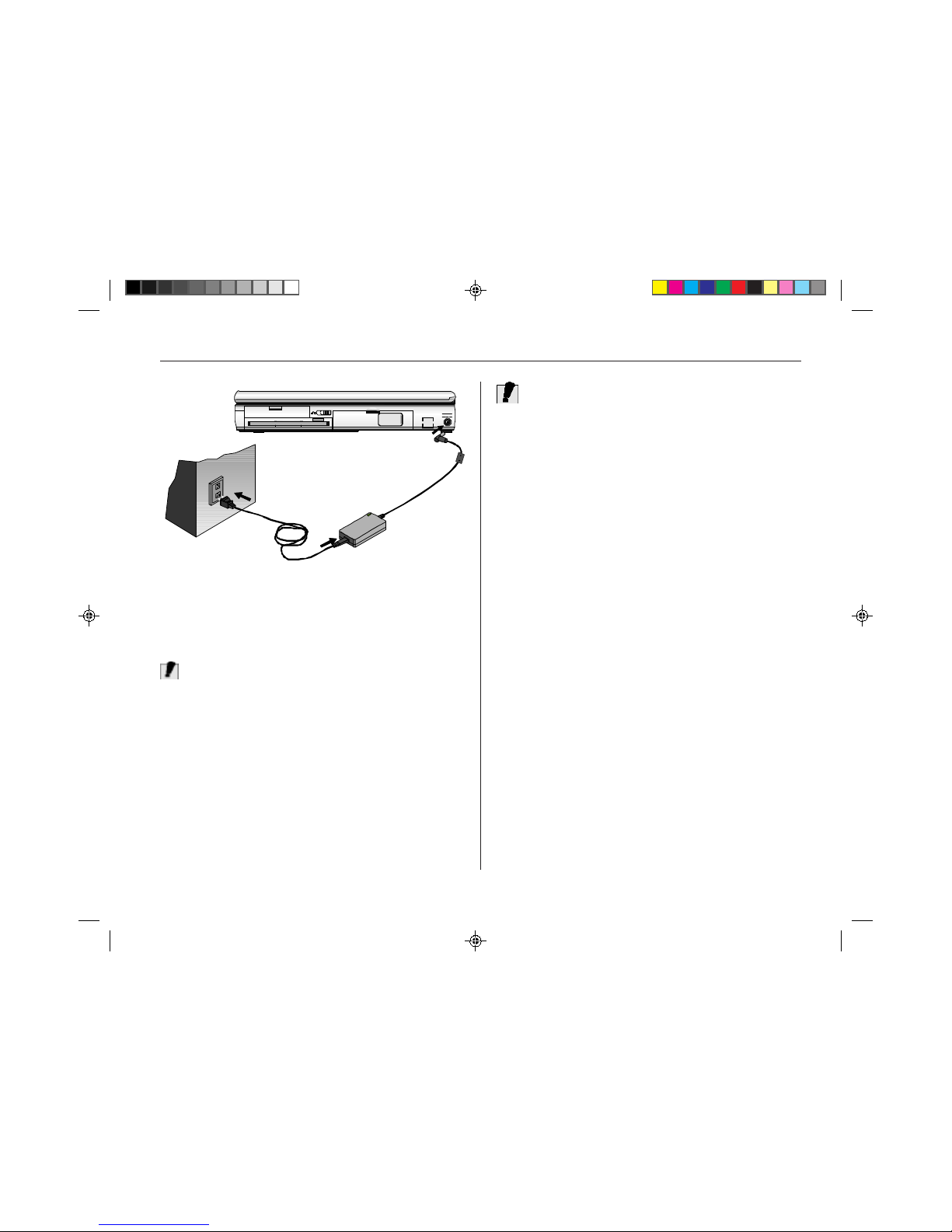
23
Figure 1-7: Connecting the AC adapter .
Connecting the AC adapter
Caution!
The best kind of AC power source to connect your
TREK 2
to
is a UPS (Uninterruptible Power Supply). Lacking this, use a
power strip with a built-in surge protector. Do not use inferior
extension cords as this may result in damage to your
TREK 2
.
The
TREK 2
comes with its own AC adapter. Do not use a
different adapter to po wer the computer , and do not use the
AC adapter to power other electrical devices. Damage to the
computer that is directly caused by using a different power
source will not be covered under warranty
Whenever possible, keep the AC adapter plugged into the
TREK 2 and an electrical outlet to recharge the battery .
Although not necessary , it is also a good idea to protect the
display panel by alwa ys lowering it when the TREK 2 is
powered off.
Caution!
Never turn off or reset your
TREK 2
while the hard disk or
floppy disk is in use and the FDD and/or HDD status icon is lit;
doing so can result in loss or destruction of your data. Always
wait at least five seconds after turning off your
TREK 2
before
turning it back on; turning the power on and off in rapid
succession can damage the
TREK 2
’s electrical circuitry .
Turning on your TREK 2 Computer
Before turning on your computer , mak e sure you are f amiliar
with its features. See Chapter 1 for more information.
Now that your TREK 2 is opened and connected to a power
source, it’s time to turn it on. Press the power button located
above the system status indicator panel (see Figure 1-3).
Hold the button down for a second or two and release.
The P ower-On Self T est (POST) will run automatically. After
the POST is completed, the computer reads the operating
system from the hard disk drive into computer memory. This
is commonly referred to as “booting” a computer .
You are now ready to run software programs and use devices
such as printers, disk drives and the CD-ROM.
To turn the TREK 2 off, save your work and close all open
applications, click on start, then shut down. In the Shut Down
Windows dialog box, select Shut Down and click Yes.

24
About the ROM BIOS
Your TREK 2 computer is configured with a customized Basic
Input/Output System (BIOS), which is a set of permanently
recorded program routines that give the computer its
fundamental operational characteristics. The BIOS also tests
the computer and determines how the computer reacts to
specific instructions that are part of programs.
The BIOS is made up of code and programs that control the
major input/output devices on the computer. The BIOS also
contains a set of boot routines called the Power-On Self Test
(POST) that check the computer when you turn it on.
About BIOS Setup
When you turn on your computer , the system is configured
using default v alues. If necessary, you can change these
system defaults by running the BIOS System Setup program
when you boot your computer . For a detailed description of
the BIOS System Setup, see Running Bios Setup (chapter
eight).
The BIOS System is a ROM (Read Only Memory) based
software utility that displa ys the system’s configuration and
provides you with a tool to set system parameters. These
parameters are stored in non-volatile battery-backed CMOS
RAM which holds this information even when the power is
turned off. Whenever the TREK 2 is turned on, the system is
configured with the values f ound in CMOS memory.
A few seconds after y ou turn on your computer , a copyright
message appears on your display screen. A memory test
message will appear next. The test continues until all
installed memory is tested. Normally, the only test routine
visible on the screen will be the memory test.
Two kinds of malfunctions can be detected during the POST:
r Error messages that indicate a failure with the hardware,
the software, or the BIOS . These critical malfunctions
prevent the computer from operating at all or could cause
incorrect results. An example of a critical error is a
microprocessor malfunction.
r Messages that furnish important information (such as
memory status) on power-on and boot processes.
These non-critical malfunctions are those that cause
incorrect results that may not be readily apparent. An
example of a non-critical error would be a memory chip
failure.
In general, if the POST detects a system board failure (a
critical error), the computer halts and generates a series of
beeps. If failure is detected in an area other than the system
board (such as the display, keyboard, or an adapter card) an
error message is displayed on the screen and testing is
stopped.
The POST does not test all areas of the computer, but only
those that allow it to be operational enough to run any
diagnostic program.
If your system does not successfully complete the POST, but
displays a blank screen, emits a series of beeps, or displays
an error code, contact Technical Support
About the Pow er -On Self Test
The Power-On Self T est (POST) runs every time you turn on
the computer . The POST checks memory, the main system
board, the display, the keyboard, the disk drive s, and other
installed options.

25
Operating system
When starting the TREK 2 for the first time , please note yo u
have either Windows 95, Windows 98 or Windows NT 4.0
already installed on your TREK 2.
Resetting the system
To reset the system, or “reboot,” press the [Ctrl] + [Alt] +
[Delete] keys simultaneously. This is known as a “warm boot.”
This key combination acts as a software reset switch when
you encounter hardware or software problems which might
lock up the TREK 2.
If this key combination does not shut down the TREK 2, you
can reset the TREK 2 by using the TREK 2’ s pow er b utton.
Should the TREK 2 lock up for some reason, pressing this
button for five seconds powers the TREK 2 off .
Adjusting contrast and brightness
After turning on your computer , you may want to adjust the
brightness of the LCD screen.
To adjust the brightness on the LCD screen, press and hold
down the [Fn] key in the lower left hand corner of the
keyboard and press the [F7] key to reduce the brightness or
[F8] to increase the brightness.
Caution!
Only use batteries that are provided by Micron Electronics. All
batteries are not the same and therefore should not be treated
as such. Using the wrong battery could cause serious damage
to your computer and yourself through toxic emissions.
Damage caused by a third party battery will not be covered by
the computer’s warranty
Inserting and removing the battery pack
The battery pack should already be inserted in your TREK 2
computer when you unpack it. If it is not inserted, follow
these directions and refer to Figure 1-8:
1. T urn off the TREK 2.
2. Open the battery bay door . Slide the battery release
latch to the left.
3. Insert the battery into the empty compartment. It is
designed so that it only fits one way. It should easily
“click” into place.
4. Slide the battery release latch to the right and close the
battery compartment cover .
To remove the battery pack:
1. T urn off the computer
2. Open the battery bay door . Slide the battery release latch
to the left.
3. Lift the battery finger grip and pull the battery from the
bay.
Operating on battery power
Your computer comes with a rechargeable battery pack that
lets you operate the computer without an external power
source. When the battery pack is fully charged, you can
operate the computer for approximately 2 hours under the
following conditions:
r The battery pack initially has a full charge.
r No peripheral devices are installed.
r The disk/CD-ROM drives run no more than 10
percent of the time
26
Figure 1-8: Inserting and removing the battery pack.
Charging the battery pack
The installed battery pack charges automatically any time the
computer is connected to the AC adapter and an external
power source. The Li-Ion battery can be fully charged in about
four hours when the computer is turned off.
It is a good idea to occasionally discharge the battery pack fully
to preserve its operating performance. For details, see
“Batteries & Battery Discharge” in Chapter 2.
Note:
A word about ergonomics
Ergonomics is the study of how people with their different
physical characteristics and ways of functioning relate to their
working environment (the furnishings and machines they use).
The goal of ergonomics is to incorporate comfort, efficiency,
and safety into the design of keyboards, computer desks,
chairs, and other items in an effort to prevent physical
discomfort and health problems in the working environment.
If your budget permits, buy ergonomically designed furniture
such as chairs, shelves, and desks that fit your physical
characteristics and work method. If you are going to be
sitting for extended periods of time, an ergonomically
designed chair may well be worth the extra expense.
You can, howev er, create an ergonomically impro ved
workstation without spending much money. Following are a
few tips to help you work effectively without a lot of physical
discomfort:
r Purchase a chair with armrests and good
back support.
r Don’t slouch when sitting; keep your back straight.·
r Place the LCD panel or external monitor so that it is a
little above ey e le v el — when using a word processor.
r Remember to Scroll Down often to ensure you are
reading or typing at the top of the screen; this will
help to prevent neck strain.
r T ry to place the LCD panel or external monitor so that
there is little glare from the sun on the monitor
r Walk around the room e very hour.
r Every half hour look away from the computer screen
for a few minutes.
r Place everything that you need to work within
easy reach.

27
2. Caring for Your
TREK 2
This chapter provides you with information on how to keep
your computer in top working condition.
Preventing problems
Your TREK 2 computer requires little hardware maintenance.
But as with any piece of electrical equipment, there are a few
simple checks and precautions that will help ensure that your
computer provides outstanding performance for many years.
r Do not block the air flow around the computer .
Maintain a distance of four inches (10 cm) between
the computer and obstructions.
r Check the cab le and pow er connectors periodically .
Keep your computer away from excessive humidity,
direct sunlight, high temperatures, and extreme
cold.
r Do not smoke near your computer.
r Do not eat near or place liquids near y our computer .
r Avoid dusty environments, as dust can cause
damage to disks and disk drives.
r Never subject your computer to sudden shocks or
extreme vibration. Do not drop it or knock it with
other equipment.
r If you suddenly move your computer from a cold
place to a warm place, undesirable moisture may
condense inside the unit. After sudden temperature
changes, let the computer come to room temperature
before using it. This allows any moisture inside the
computer to evaporate.
r When possible, use a high-quality electrical surge
protector when your computer is powered by the
AC adapter. It is also a good idea to unplug your
computer when it is not in use.
r Ensure that your hands are clean when you use the
touch pad to prevent oil and dirt build-up which can
impair the touch pad operation.
r Clean your computer’s exterior casing occasionally
with a soft cloth. Unplug the computer from the
wall outlet and remove the battery pack before
cleaning. If you use a cleanser, make sure that it is
only a mild detergent. Never use solvents like
thinner or benzene, or abrasive cleanser , because
these may damage the cabinet. After cleaning, allow
30 minutes drying time.
r Remember to clean your display at regular intervals.
Spray window cleanser onto a soft cloth and then
wipe the display. Do not spray the cleanser directly
onto the display.
r Clean your keyboard when needed. This can be
done with a soft cloth as well as with a keyboard
vacuum cleaner .

28
Caution!
There is a danger of explosion if battery is incorrectly
replaced. Replace only with the same or equivalent type
recommended by the manufacturer . Dispose of used
batteries according to the manufacturer’s instructions.
Traveling with your computer
For safety, security, and convenience when tr aveling with your
computer, follo w these guidelines:
r Before traveling, save your data by backing it up
onto floppy diskettes.
r Take along an extra backup cop y of your data.
r Do not travel with a diskette in the floppy disk
drive.
r Do not transport the TREK 2 with the power on. This
may result in loss of data and/or damage to the hard
disk drive.
r Before traveling, disconnect the AC adapter from the
computer.
r Always carry either a spare fully charged battery
pack, and the AC adapter .
r When carrying the computer, take care not to b ump it
into things. The computer cannot take the kind of
treatment that you might give a briefcase.
Safety instructions
1. Unplug the TREK 2 from the wall outlet before
cleaning. Do not use liquid cleaners or aerosol
cleaners. Use a damp cloth for cleaning.
2. Do not press on or store any object on the LCD cover
when it is closed since it may cause the LCD to
break.
3. Do not attempt to service the TREK 2 yourself.
Unplug the TREK 2 from the wall outlet and ref er
servicing to an authorized dealer.
4. When replacement of components is required, be
sure to replace only with components provided by
the manufacturer. Unauthorized substitutions may
result in safety hazards.
Power
1. This electronic device should be operated from the
type of power source indicated on the marking label.
If you are not sure of the type of power available,
consult your dealer or local power company.
2. This computer is shipped with its o wn AC adapter .
Do not use the computer with a different adapter .
3. Do not allow anything to rest on the power cord. Do
not place the TREK 2 where people will w alk on the
cord.
4. When you disconnect cords, remember to pull them
by the plugs and not by the cords themselves. This
will prev ent damage to the cords, plugs, ports, and
jacks.
5. If an extension cord is used with this TREK 2, make
sure that the total ampere ratings of the products
plugged into the extension cord do not exceed the
extension cord ampere rating. Also , make sure that
the total current of all products plugged into the wall
outlet does not exceed 15 amperes.
4. Replace only with the same or equivalent type of
battery recommended by the manufacturer or the
authorized dealer.
5. The battery will lose its charge when stored for a
long time. Fully charge the battery before you use it
again.
Battery
1. Do not disassemb le the battery. The chemicals
inside can damage skin and clothing.
2. K eep the battery pack awa y from fire.
3. Do expose the battery to rain.

29
Taking care of the LCD screen
You can extend the life of the LCD screen by caring for the
screen as follows:
r Avoid scratching the surface of the screen. The front
polarizer is easily damaged.
r Use a soft, lint-free cloth for cleaning the LCD
screen.
r Do not allow water droplets to remain on the screen.
Water can cause permanent staining.
r Do not expose the LCD screen to bright sunlight or
ultra-violet radiation.
r Do not expose the LCD screen to extreme
temperatures. F reezing and liquefaction (fusing or
melting) of the liquid crystals may result in damage
to the display.
r Whenever possible, hand-carry the computer in its
carrying case.
r If you must ship your computer as freight or
baggage, pack it carefully. Use the original cartons
and foam cushions, if possible. If they are not
available, use sturdy cartons and cushion the
computer well on all sides.
Batteries and battery discharge
It is a good idea to occasionally discharge the battery pack
fully to preserve its operating performance. Repeatedly
recharging the battery pack when it has not discharged
completely can decrease the capacity of the battery pack. In
the battery pack there is a GAS-GAUGE IC to record the
charge/discharge status of the battery .
You can also extend the life of the battery pack by using the
computer’s power-sa ving features.
Discharging and recharging the battery pack
1. Disconnect the AC adapter from the external power
source, then from the computer.
2. Turn on the computer.
3. Ignore the power failure signals (i.e., battery
warning beeps).
4. When the battery is fully discharged (that is, when
the computer goes off), attach an external power
source and fully recharge the battery. The battery
charge icon on the Status panel indicates when the
battery is fully charged.
An incorrect report of the battery status may be shown due to
lost data of the GAS-GAUGE IC caused b y battery overdischarge. One reason for the battery to over-discharge may
be that the battery has not been charged for a long time. If
this is the case, a learning cycle is recommended to correct
this problem.
The learning cycle is listed as follows:
1. Turn off the TREK 2 and use the AC adapter to
charge the computer’s battery pack to full.
2. Fully discharge and recharge the battery pack as
described above.
3. Remove the battery pack and check the GASGAUGE IC . If the indicator shows 100% capacity
then the learning cycle is done. Otherwise repeat the
learning cycle mentioned above.
4. If after you try the second time and still fail to get
the battery pack to 100% capacity, contact your
dealer.

30
Safety precautions
Required safety features have been installed in the computer
to protect you from injury . However, you should use good
judgment to identify potential safety hazards:
r Read all of these instructions before using your
TREK 2 and save them for later use.
r Follow all warnings and instructions marked on the
product.
r Unplug this product from the wall outlet before
cleaning. Do not use liquid or aerosol cleaners. T o
clean, wipe with a damp cloth.
r Do not use this product near water.
r Do not place this product on an unstable cart, stand,
or table. The product may fall, causing serious
damage to the product.
r Slots and openings in the cabinet are for ventilation.
r To ensure reliable operation of the product and to
protect it from overheating, these openings must not
be blocked or covered. This product should nev er
be placed near or over a r adiator or heater.
r Never push objects of any kind into this product
through cabinet openings, as they may touch
dangerous voltage points or short out parts that
could result in fire or electric shock. Never spill
liquid of any kind on the product.
r This product should be operated from the type of
power source indicated on the marking label. If you
are not sure of the type of power available, consult
your dealer or local power company.
r If you use an extension cord with this product, make
sure that the total of the ampere ratings on the
products plugged into the extension cord does not
exceed the e xtension cord ampere rating. Also ,
make sure that the total of all products plugged into
the wall outlet does not exceed 15 amperes.
r Adjust only those controls that are covered by the
operating instructions, since improper adjustment of
other controls may result in damage and may
require extensive work by a qualified technician to
restore the product to normal operation.
r Do not attempt to service this product yourself, as
opening or removing the cabinet may expose you to
dangerous voltage. Refer all servicing to service
personnel. Opening cabinent ma y void warranty.
r Unplug this product from the wall outlet and refer
servicing to qualified service personnel under the
following conditions:
r If the power cord or plug is damaged or frayed
r If the product has been exposed to rain or water
r If the product does not operate normally when the
operating instructions are followed
r If the product has been dropped or the cabinet has
been damaged
r If the product exhibits a distinct change in
performance, indicating a need for service
r Unless the manufacturer indicates that a device can
be hot-swapped, you should turn off the computer
before connecting peripheral devices.
r Replace the battery pack only with the same type as
the original. Use of another battery pack may
present a risk of fire or explosion.
r Do not use or leave the AC Adapter near a fire,
stove, or other hot environment.
r Do not immerse the AC Adapter in water or expose
it to moisture.
r Do not cover the AC adapter with anything (such as
a book, box, paper , etc.).
Warning!
The battery pack may explode if handled incorrectly . Do
not disassemble the battery or dispose of it in fire. K eep
away from children and dispose of the used battery
promptly .
 Loading...