

Page 1
LifeGait Motion Sensors
User Manual
Revision: 1.00
Document Title
Version
Finale Date
Status
Document Control ID
LifeGait Motion Sensors User Guide
1.00
2016-03-22
Released
LifeGait Motion Sensors
1
Page 2

Contents
.
.
.
.
1 Introduction .....................................................................................................................................................
2 Product Overview ............................................................................................................................................
2.1 Appearance .......................................................................................................... 3
2.2 Switch/5PIN Interface Description ........................................................................ 3
2.3 LED Description ................................................................................................... 4
3 Getting Started ............................................................................................................. ...................................
3.1 Parts List .............................................................................................................. 5
3.2 Battery Charging .................................................................................................. 5
3.3 LifeGait Motion Sensors Data Cable .................................................................... 6
3.4 Power on/Power off .............................................................................................. 6
4 Trouble shooting and Safety info .....................................................................................................................
4.1 Trouble shooting .................................................................................................. 7
4.2 Safety info ............................................................................................................ 7
2
Page 3
1 Introduction
LifeGait Motion Sensors is a Tracker which is designed for getting information of human
motion , including WIFI function meanwhile(e.g. a wearable product). With superior
receiving sensitivity, WIFI frequencies 2.4GHz. Based on the embedded wireless protocol,
LIFEGAIT MOTION SENSORS can communicate with the backend server through WIFI
function, and transfer data of sensor, device information etc…
2 Product Overview
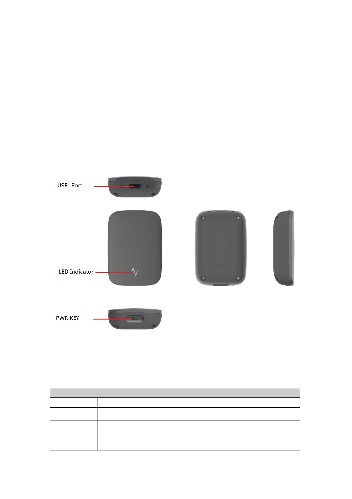
2.1 Appearance
Figure 1-1
2.2 Switch/5PIN Interface Description
Button /5PIN Interface Description
KEY/interface Description
SWITCH
5PIN interface
3
Power on/off LifeGait Motion Sensors
Connect a 3.8V Li-ion or Li-Polymer battery can power on LIFEGAIT
MOTION SENSORS
Connect a 5V DC adapter can charge the internal battery
Page 4
Backend server developer or administrator can use the data cable to
configure LIFEGAIT MOTION SENSORS
end user).
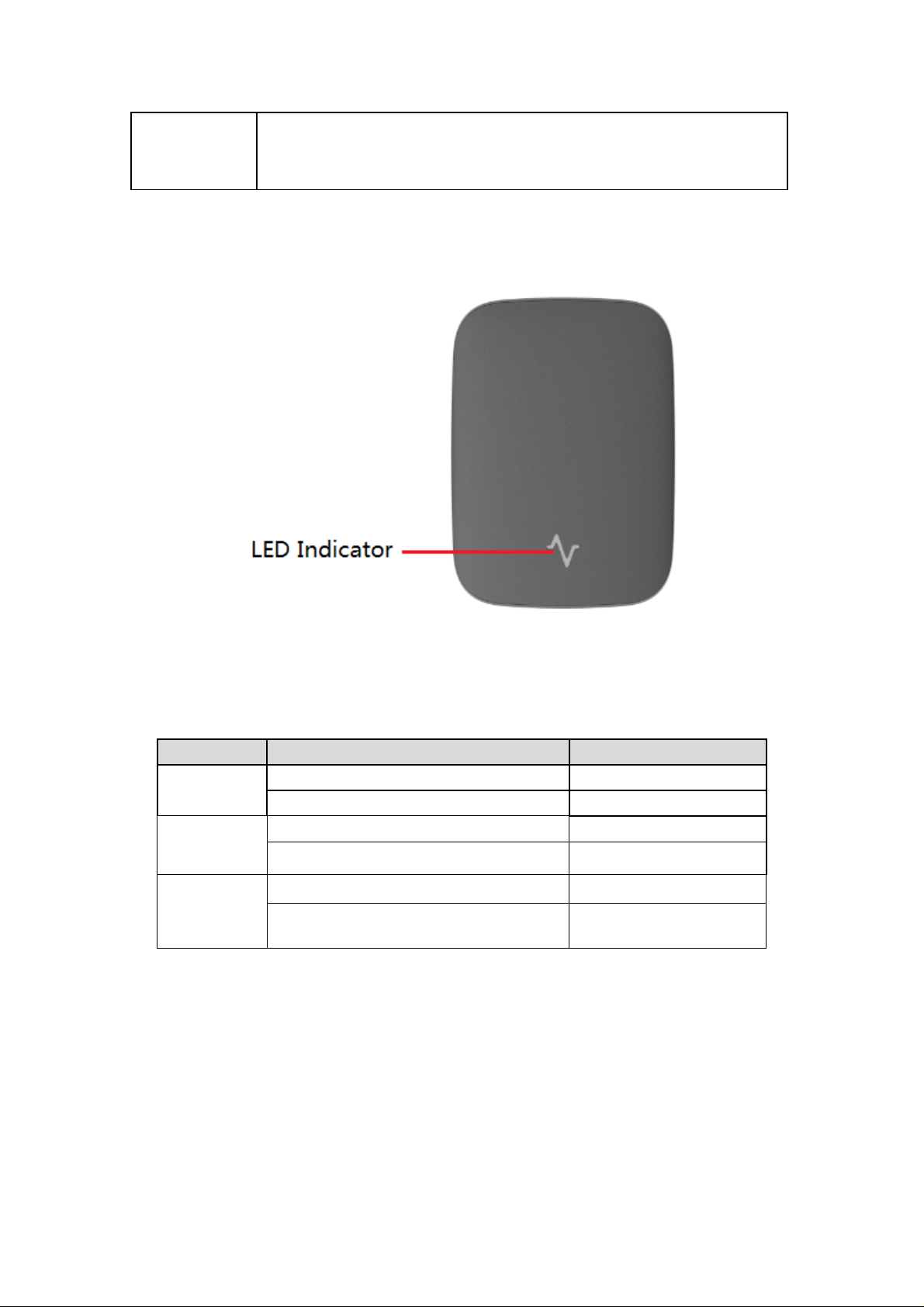
2.3 LED Description
(by RD or engineer not by
Figure 1-2
There are Three LED lights in LifeGait Motion Sensors device, the description as
following.
Light Event State
POWER
LED
Charging
LED
LOW
BATTERY
LED
Power On Blue LED Solid
Power Off Blue LED Dark
Fully charged Green LED Dark
In charging Green LED Solid
Low battery Red LED Solid
High battery Red LED Dark
4
Page 5
3 Getting Started
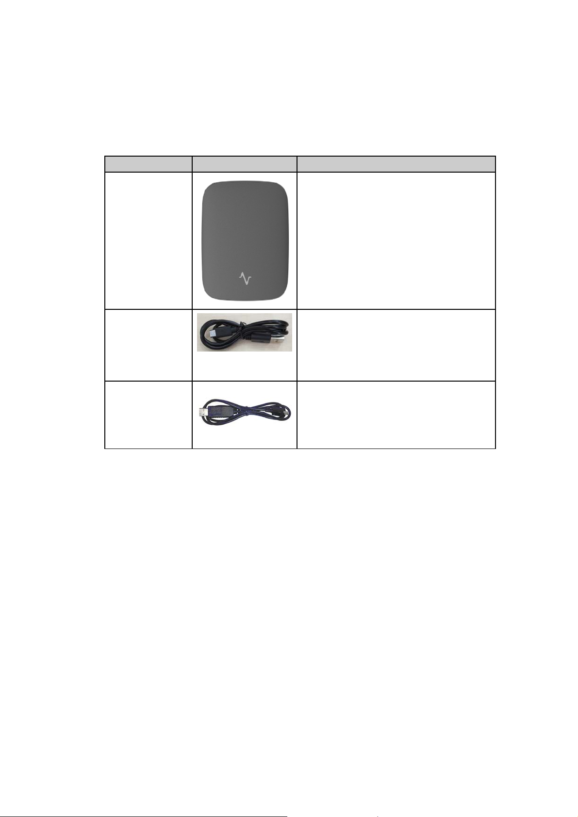
3.1 Parts List
Name Picture Remark
LifeGait Motion
Sensors
LifeGait Motion Sensors
USB Cable
LifeGait Motion
Sensors Data
and charger
Cable
It is used to charge the internal battery of
LifeGait Motion Sensors
the data cable which can be used for
firmware upgrading and debug.
It also includes the charger interface
RD or engineer not by end user).
3.2 Battery Charging
The following items are suggestion for battery charge, please pay more attention.
Please connect AC-DC power adapter with LIFEGAIT MOTION SENSORS
device.
Insert the AC-DC power adapter into the power socket.
During the charging process, the
When the battery is fully charged, the
You can also charge the battery using charging cable which connects
LIFEGAIT MOTION SENSORS device with the Adapter.
Charging will last about 3 hours.
Note: If the LifeGait Motion Sensors device is firstly used, please make sure the
battery is fully charged, which will make the life of battery much longer.
LOW BATTERY LED light will flash slow.
Power LED light will be Ever-light.
(by
5
Page 6
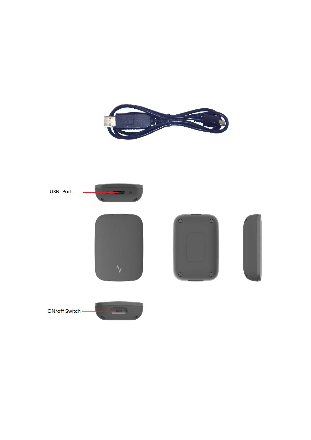
3.3 LifeGait Motion Sensors Data Cable
LifeGait Motion Sensors Data Cable is a cable with a 5PIN connector.
The data cable is used for data download, which will be used for firmware update
or configuration and can be used for charging at the same time (by RD or
engineer not by end user).
Figure 2-1
3.4 Power on/Power off
Figure 2-2
Power on:
Push the On/off Switch to the right side then power on LIFEGAIT MOTION
SENSORS. Note that, the Power on LED(Blue) light will be solid.
Power off:
Push the On/off Switch to the left side then power off LIFEGAIT MOTION
SENSORS. Note that, the Power on LED(Blue) light will be dark., this
indicates the LIFEGAIT MOTION SENSORS has been powered off..
6
Page 7
4 Trouble shooting and Safety info
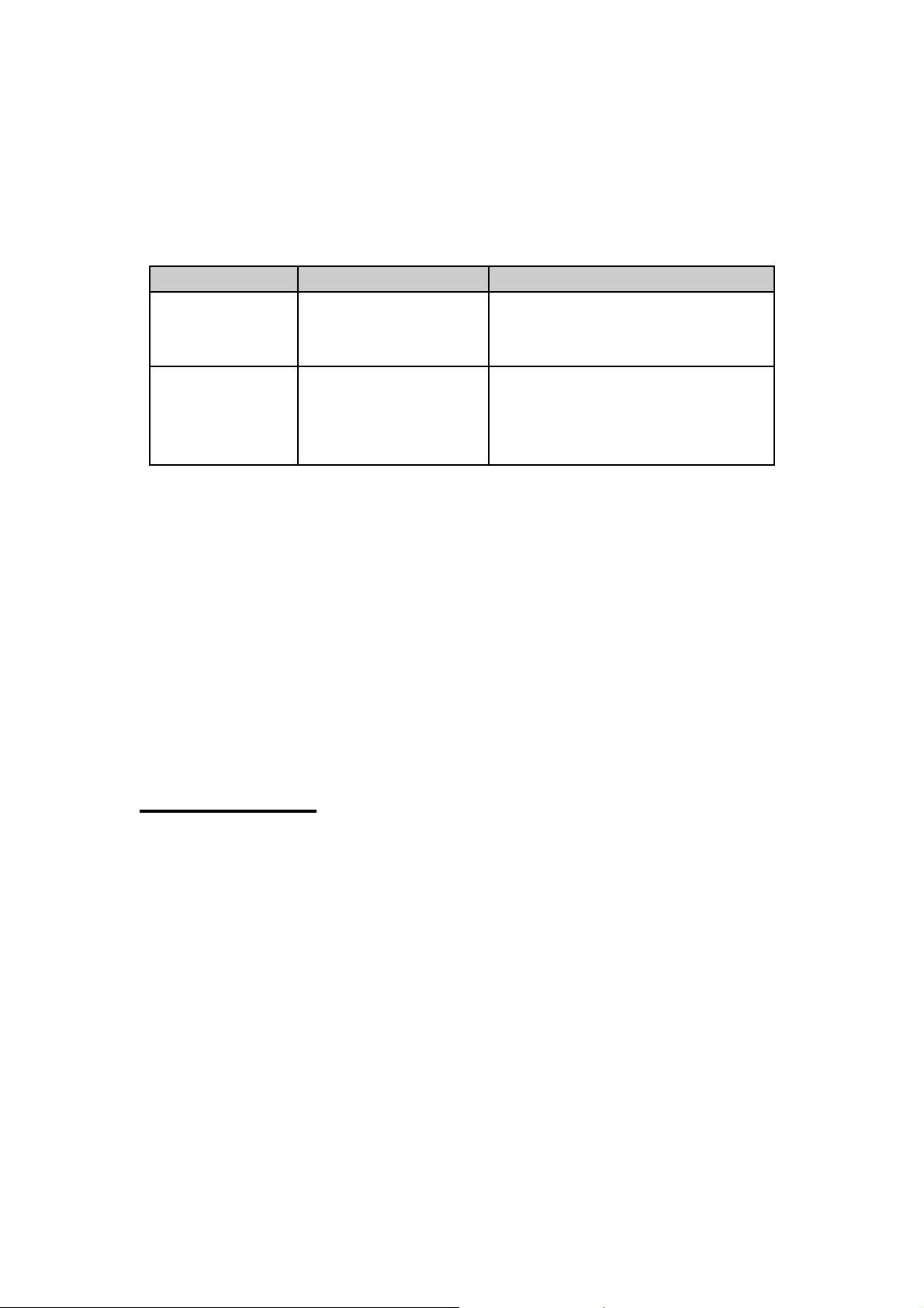
4.1 Trouble shooting
Trouble Possible Reason Solution
Unable to power
off
LifeGait
Motion Sensors
Battery can not be
charged
4.2 Safety info
The following items are suggestion for safety use, please pay more attention.
Please do not disassemble the device by yourself.
Please do not put the device on the overheating or too humid place, avoid
exposure to direct sunlight. Too high temperature will damage the device or
even cause the battery explosion.
Please do not use
equipment.
On/off Switch is
damage
.
The battery has not
been used for too long
time and has been
locked.
LifeGait Motion Sensors on the airplane or near medical
The device will power off when push
the On/off Switch to the left side
Using a external power source with
3.6V to 4.2V DC power supply to
active the battery or apply for after
sale help.
FCC Caution.
§ 15.19 Labelling requirements.
This device complies with part 15 of the FCC Rules. Operation is subject to the
condition that this device does not cause harmful interference.
§ 15.21 Information to user.
Any Changes or modifications not expressly approved by the party responsible
for compliance could void the user's authority to operate the equipment.
§ 15.105 Information to the user.
Note: This equipment has been tested and found to comply with the limits for a
Class B digital device, pursuant to part 15 of the FCC Rules. These limits are
designed to provide reasonable protection against harmful interference in a
residential installation. This equipment generates uses and can radiate radio
frequency energy and, if not installed and used in accordance with the
instructions, may cause harmful interference to radio communications.
However, there is no guarantee that interference will not occur in a particular
7
Page 8

installation. If this equipment does cause harmful interference to radio or
television reception, which can be determined by turning the equipment off and
on, the user is encouraged to try to correct the interference by one or more of
the following measures:
-Reorient or relocate the receiving antenna.
-Increase the separation between the equipment and receiver.
-Connect the equipment into an outlet on a circuit different from that to which
the receiver is connected.
-Consult the dealer or an experienced radio/TV technician for help.
This device complies with Part 15 of the FCC Rules. Operation is subject to the
following two conditions: (1) This device may not cause harmful interference.
(2) This device must accept any interference received, including interference
that may cause undesired operation.
RF Radiation Exposure Statement:
1. This equipment compliance with FCC RF radiation exposure limits set forth
for an uncontrolled environment for body-worn configuration.
2. The maximum summation of SAR was0.03 W/Kg(1g) for Body.
The antenna(s) used for this transmitter must not be co-located or
operating in conjunction with any other antenna or transmitter.
8
 Loading...