

ATW User Manual
Revision: 1.1
Document Title
Version
Finale Date
Status
Document Control ID
ATW User manual
1.1
2018-05-25
Released
TRACKER ATW
Contents
1

1 Introduction .................................................................................................................................... 3
2 Product Overview .......................................................................................................................... 3
2.1 Appearance .......................................................................................................................... 3
2.2 Buttons/12PIN Interface Description .................................................................................. 3
2.3 LED Description ................................................................................................................. 4
3 Getting Started ............................................................................................................................... 5
3.1 Parts List ............................................................................................................................. 5
3.2 Battery Charging ................................................................................................................. 5
3.3 ATW Data Cable ................................................................................................................. 5
3.4 Power on/Power off ............................................................................................................. 6
4 Frequency ....................................................................................................................................... 6
5 Trouble shooting and Safety info ................................................................................................... 7
5.1 Trouble shooting ................................................................................................................. 7
5.2 Safety info ........................................................................................................................... 7
2
1 Introduction
ATW is a powerful GPS locator which is designed for vehicle and assets tracking. With superior
receiving sensitivity, fast WCDMA frequencies 850/1900/1700. Its location can be real time or
schedule tracked by backend server or specified terminals. Based on the embedded wireless
tracking protocol, ATW can communicate with the backend server through WCDMA and GSM
network, and transfer reports of emergency, Geo-fencing, device status and scheduled GPS
position etc… Service provider is easy to setup their tracking platform based on the functional
wireless tracking protocol.
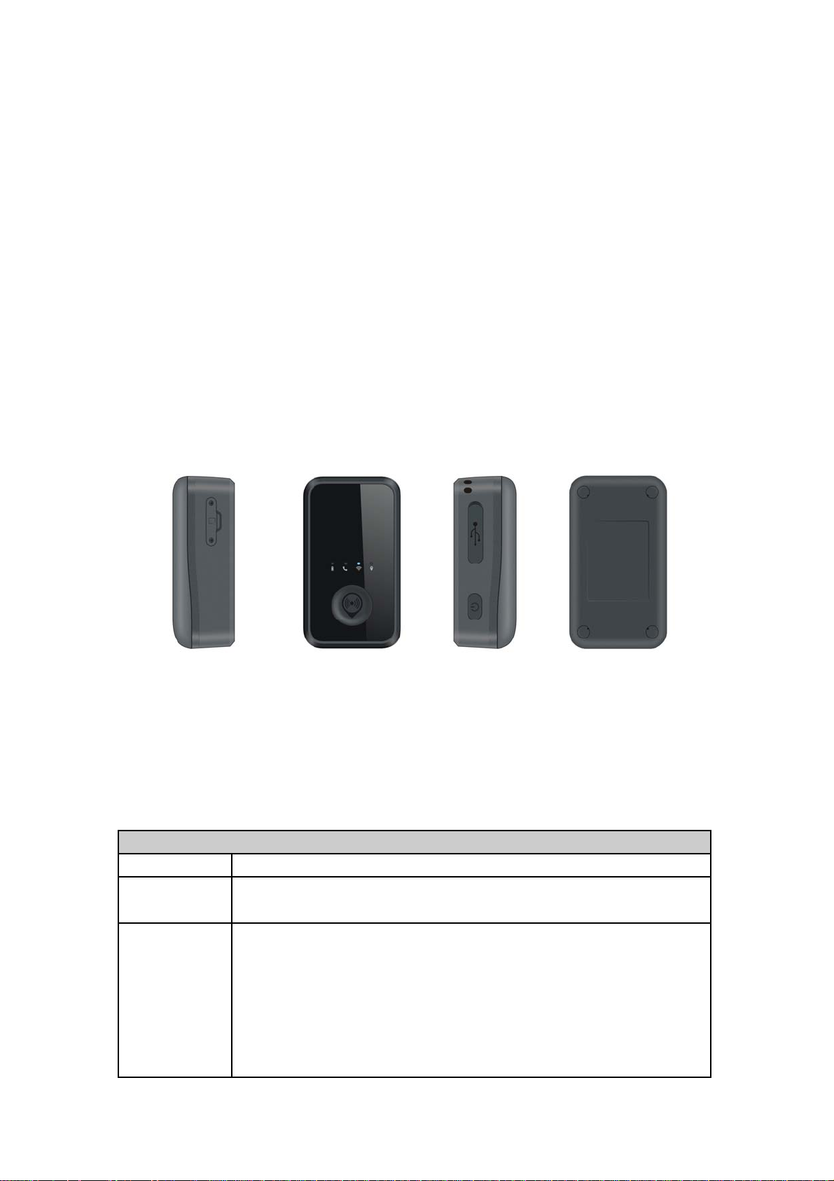
2 Product Overview
2.1 Appearance
Figure 1-1
2.2 Buttons/12PIN Interface Description
Button /12PIN Interface Description
KEY/interface Description
Power Key
Function Key
Power on ATW
Power off ATW (If power key is enabled)
Geo-Fence mode
Long press the key to enable/disable Geo-Fence ID0
Geo-Fence in current position mode
Long press the key t o e nable/disable Geo-Fenc e ID0 . If e nable G eo-Fence
ID0, using the current position as the centre of Geo-Fence 0.
SOS mode (default)
Long press the key to active SOS alarm
3

12PIN
interface
Connect a 3.7V Li-ion or Li-Polymer battery can power on ATW
Backend server developer or administrator can use the data cable to configure
ATW (by RD or engineer not by end user).
Reset Key
Click th e key will turn off i nternal VB AT when OS is ab normal, a nd t hen
press Power Key to restart ATW.
2.3 LED Description
Figure 1-2
There are four LED lights in ATW device, the description as following.
Light Event State
Power LED Power on and normal Dark
Fully charged Solid
In charging Slow flash
WCDMA
LED
WIFI LED
GPS LED GPS fixed Fast flash
Power on and normal Slow flash
Power off Dark
WIFI on Slow flash
WIFI off Dark
GPS has been turned off Dark
4

3 Getting Started
3.1 Parts List
Name Picture Remark
ATW Locater
The WCDMA/GPS locator.
ATW Data and
charger Cable
It the d ata cable w hich c an be used for
firmware upg rading a nd configuration (by
RD or engineer not by end user).
It also includes the charger interface on the
ATW.
3.2 Battery Charging
The following items are suggestion for battery charge, please pay more attention.
During th e charging process, the
is fully charged, the
You can charge the battery using charging cable which connects ATW device with
the Adapter.
Charging will last about 5 hours.
Note: If the ATW device is firstly used, please make sure the battery is fully charged, which
will make the life of battery much longer.
Power LED light will be Ever-light.
Power LED light will slow flash. When t he battery
3.3 ATW Data Cable
ATW Data Cable is a cable with a 12PIN connector.
The d ata c able is used for data dow nload, w hich w ill be use d for firm ware upda te or
configuration and can be used for charging at the same time (by RD or engineer not by
end user). .
5

3.4 Power on/Power off
Figure 2-1
Figure 2-2
Power on:
Press the Power key at least 3 sec onds and rele ase it to power on ATW device .
Note that, the
Power off:
Press the power key about 3 seconds; Power LED light will light for a moment and
then turn off, which indicates that ATW device has been powered off.
Power LED light will light for a moment and then turn off.
Note: the u ser can no t power off ATW if the power key is disabled by
protocol.
4 Frequency
GSM850:824-849MHz (TX), 869-894MHz (RX);
PCS1900:1850-1910MHz (TX), 1930-1990MHz (R
WCDMA B5:824-849MHz (TX), 869-894MHz (RX);
WCDMA B2:1850-1910MHz (TX), 1930-1990MHz (RX);
WCDMA B4:1710-1755MHz (TX), 2110-2155MHz (RX);
GPS:1575.42MHz
X);
6

5 Trouble shooting and Safety info
5.1 Trouble shooting
Trouble Possible Reason Solution
Messages can’t be
reported to the
backend server by
Mobile network.
Unable to power off
ATW.
Battery can not be
charged
ATW can’t fix GPS
successfully.
APN is wrong. Some
APN can not visit the
internet directly.
The IP address or port of
the backend server is
wrong.
The function of power key
was disabled by
AT+GTFKS.
The battery has not been
used for too long time and
has been locked.
The GPS signal is weak. Please move ATW to a place with open
Ask the network operator for the right
APN.
Make sure the IP address for the
backend server is an identified address
in the internet.
Enable the function of power key by
AT+GTFKS.
Using a external power source with 3.6V
to 4.2V DC power supply to active the
battery or apply for after sale help.
sky.
It is better to let the top surface face to
the sky. (The same surface with
indication LED)
5.2 Safety info
The following items are suggestion for safety use, please pay more attention.
Please do not disassemble the device by yourself.
Please do not put the device on the overheating or too humid place, avoid exposure
to direct sunlight. Too high temperature will damage t he device or even cause the
battery explosion.
Please do not use ATW on the airplane or near medical equipment.
FCC Caution.
15.19 Labelling requirements.
§
This device complies with par
conditi
ons:
(1) This device may not cause harmful interference, and
(2) This device must accept any interference received, including interference that may cause
undesired operation.
15.21 Information to user.
§
t 15 of the FCC Rules. Operation is subject to the following two
7

Any Changes or m odifications not expres sly approved by the party responsible for
compliance could void the user's authority to operate the equipment.
§ 15.105 Information to the user.
Note: This equipment has been tested and found to comply with the limits for a Class
B digital device, pursuant to part 15 of the FCC Rules. These lim its ar e designed to
provide reasonable protection against harmful interference in a residential installation.
This equipm ent generates uses and can ra diate radio frequency ener gy and, if not
installed and used in accordance with the instructions, may cause harmful interference
to radio communications. However , there is no guaran tee that in terference will n ot
occur in a particular insta llation. If this equipm ent does cause harmful interference to
radio or television reception, which can be determined by turning the equipm ent of f
and on, the user is encouraged to try to correct the interf erence by one or more of the
following measures:
-Reorient or relocate the receiving antenna.
-Increase the separation between the equipment and receiver.
-Connect th e equipm ent into an outlet on a cir cuit dif ferent f rom that to which the
receiver is connected.
-Consult the dealer or an experienced radio/TV technician for help.
This equipment complies with FCC radiation exposure limits set forth for an uncontrolled
env
ironment. This equipment should be installed and operated with minimum distance
20cm between the radiator & your body.
ISED RSS Warning/ISED RF Exposure Statement
ISED RSS Warning:
This device com plies with Innovation, Sc ience and Econom ic Development Canada
licence-exempt RSS standard(s). Operation is subject to the following two conditions:
(1) this dev ice m ay not caus e interferen ce, an d (2) th is device m ust accep t any
interference, including interference that may cause undesired operation of the device.
Le présent appareil est conform e aux CNR d'ISED applic ables aux appareils radio
exempts de licence. L'exploitation est autorisée aux deux conditions suivantes:
(1) l'appareil ne doit pas produire de brouillage, et
(2) l'utilisateur de l'appareil doit accepter tout brouillage radioélectrique subi, même si
le brouillageest susceptible d'en compromettre le fonctionnement.
ISED RF exposure statement:
This equipm ent com plies with IS ED ra diation exposure lim its set forth for an
uncontrolled environm ent. This equipm ent should be installed and operated with
minimum distance 20cm between the radiator& your body . This transmitter must not
be co-located or operating in conjunction with any other antenna or transmitter.
Le rayonnem ent de la classe b repecte ISED fixaient un environnem ent non
contrôlés.Installation et m ise enœuvre de ce m atériel devrait avec échan geur distance
minimale entre 20 cm ton corps.Lanceurs ou ne peuvent pas coexister cette antenne
ou capteurs avec d’autres.
8
 Loading...