

Page 1
Configuration and Use Manual
Micro Motion® 9739 MVD Transmitters
MMI-20016855, Rev AC
April 2013
Page 2

Micro Motion customer service
Email
• Worldwide: flow.support@emerson.com
• Asia-Pacific: APflow.support@emerson.com
North and South America Europe and Middle East Asia Pacific
United States 800-522-6277 U.K. 0870 240 1978 Australia 800 158 727
Canada +1 303-527-5200 The Netherlands +31 (0) 318 495 555 New Zealand 099 128 804
Mexico +41 (0) 41 7686 111 France 0800 917 901 India 800 440 1468
Argentina +54 11 4837 7000 Germany 0800 182 5347 Pakistan 888 550 2682
Brazil +55 15 3238 3677 Italy 8008 77334 China +86 21 2892 9000
Venezuela +58 26 1731 3446 Central & Eastern +41 (0) 41 7686 111 Japan +81 3 5769 6803
Russia/CIS +7 495 981 9811 South Korea +82 2 3438 4600
Egypt 0800 000 0015 Singapore +65 6 777 8211
Oman 800 70101 Thailand 001 800 441 6426
Qatar 431 0044 Malaysia 800 814 008
Kuwait 663 299 01
South Africa 800 991 390
Saudia Arabia 800 844 9564
UAE 800 0444 0684
Page 3

Contents
Contents
Part I Getting Started
Chapter 1 Before you begin .............................................................................................................3
1.1 About this manual .........................................................................................................................3
1.2 Transmitter model code ................................................................................................................3
1.3 Communications tools and protocols ............................................................................................3
1.4 Additional documentation and resources ......................................................................................4
Chapter 2 Quick start .......................................................................................................................5
2.1 Power up the transmitter ...............................................................................................................5
2.2 Check flowmeter status .................................................................................................................5
2.3 Make a startup connection to the transmitter ................................................................................6
2.4 Characterize the flowmeter (if required) ........................................................................................7
2.4.1 Sample sensor tags .........................................................................................................8
2.4.2 Flow calibration parameters (FCF, FT) .............................................................................9
2.4.3 Density calibration parameters (D1, D2, K1, K2, FD, DT, TC) .........................................10
2.5 Verify mass flow measurement ....................................................................................................10
2.6 Verify the zero .............................................................................................................................11
2.6.1 Verify the zero using ProLink II ......................................................................................11
2.6.2 Terminology used with zero verification and zero calibration ........................................12
Part II Configuration and commissioning
Chapter 3 Introduction to configuration and commissioning .........................................................17
3.1 Configuration flowchart ..............................................................................................................17
3.2 Default values and ranges ............................................................................................................18
3.3 Enable access to the off-line menu of the display .........................................................................19
3.4 Disable write-protection on the transmitter configuration ..........................................................19
3.5 HART security ..............................................................................................................................19
3.6 Restore the factory configuration ................................................................................................20
Chapter 4 Configure process measurement ...................................................................................21
4.1 Configure mass flow measurement .............................................................................................21
4.1.1 Configure Mass Flow Measurement Unit .......................................................................21
4.1.2 Configure Flow Damping ..............................................................................................24
4.1.3 Configure Mass Flow Cutoff ..........................................................................................25
4.2 Configure volume flow measurement for liquid applications .......................................................26
4.2.1 Configure Volume Flow Type for liquid applications ......................................................27
4.2.2 Configure Volume Flow Measurement Unit for liquid applications ................................27
4.2.3 Configure Volume Flow Cutoff ......................................................................................30
4.3 Configure gas standard volume (GSV) flow measurement ...........................................................31
4.3.1 Configure Volume Flow Type for gas applications .........................................................32
4.3.2 Configure Standard Gas Density ....................................................................................32
4.3.3 Configure Gas Standard Volume Flow Measurement Unit .............................................33
4.3.4 Configure Gas Standard Volume Flow Cutoff ................................................................36
Configuration and Use Manual i
Page 4

Contents
4.4 Configure Flow Direction .............................................................................................................37
4.4.1 Options for Flow Direction ............................................................................................38
4.5 Configure density measurement ................................................................................................. 42
4.5.1 Configure Density Measurement Unit ...........................................................................43
4.5.2 Configure slug flow parameters ....................................................................................44
4.5.3 Configure Density Damping ..........................................................................................45
4.5.4 Configure Density Cutoff .............................................................................................. 46
4.6 Configure temperature measurement .........................................................................................47
4.6.1 Configure Temperature Measurement Unit .................................................................. 47
4.6.2 Configure Temperature Damping .................................................................................48
4.7 Configure the petroleum measurement application ....................................................................49
4.7.1 Configure petroleum measurement using ProLink II ..................................................... 49
4.7.2 Configure petroleum measurement using the Field Communicator ..............................50
4.7.3 API reference tables ......................................................................................................51
4.8 Configure the concentration measurement application .............................................................. 53
4.8.1 Configure concentration measurement using ProLink II ................................................53
4.8.2 Configure concentration measurement using the Field Communicator ........................55
4.8.3 Standard matrices for the concentration measurement application ..............................57
4.8.4 Derived variables and calculated process variables ........................................................58
4.9 Configure pressure compensation ...............................................................................................60
4.9.1 Configure pressure compensation using ProLink II ........................................................60
4.9.2 Configure pressure compensation using the Field Communicator ................................ 62
4.9.3 Options for Pressure Measurement Unit ....................................................................... 63
Chapter 5 Configure device options and preferences .....................................................................65
5.1 Configure the transmitter display ................................................................................................65
5.1.1 Configure the language used for the display ................................................................. 65
5.1.2 Configure the process variables shown on the display ...................................................66
5.1.3 Configure the precision of variables shown on the display .............................................67
5.1.4 Configure the refresh rate of data shown on the display ................................................68
5.1.5 Enable or disable automatic scrolling through the display variables .............................. 68
5.1.6 Enable or disable the display backlight ..........................................................................69
5.1.7 Enable or disable Status LED Blinking ............................................................................ 69
5.2 Enable or disable operator actions from the display .....................................................................69
5.2.1 Enable or disable Totalizer Start/Stop from the display ..................................................70
5.2.2 Enable or disable Totalizer Reset from the display .........................................................70
5.2.3 Enable or disable the Acknowledge All Alarms display command ..................................71
5.3 Configure security for the display menus ....................................................................................72
5.4 Configure response time parameters .......................................................................................... 73
5.4.1 Configure Update Rate ................................................................................................. 73
5.5 Configure alarm handling ............................................................................................................75
5.5.1 Configure Fault Timeout ...............................................................................................75
5.5.2 Configure Status Alarm Severity ....................................................................................76
5.6 Configure informational parameters ........................................................................................... 79
5.6.1 Configure Descriptor .................................................................................................... 79
5.6.2 Configure Message .......................................................................................................79
5.6.3 Configure Date ............................................................................................................. 80
5.6.4 Configure Sensor Serial Number ................................................................................... 80
5.6.5 Configure Sensor Material .............................................................................................81
5.6.6 Configure Sensor Liner Material .................................................................................... 81
5.6.7 Configure Sensor Flange Type .......................................................................................81
Chapter 6 Integrate the meter with the control system ..................................................................83
ii Micro Motion® 9739 MVD Transmitters
Page 5

Contents
6.1 Configure the mA output ............................................................................................................83
6.1.1 Configure mA Output Process Variable .........................................................................84
6.1.2 Configure Lower Range Value (LRV) and Upper Range Value (URV) ...............................86
6.1.3 Configure AO Cutoff .....................................................................................................87
6.1.4 Configure Added Damping ...........................................................................................89
6.1.5 Configure mA Output Fault Action and mA Output Fault Level ......................................90
6.2 Configure the frequency output ..................................................................................................91
6.2.1 Configure Frequency Output Power Source ..................................................................92
6.2.2 Configure Frequency Output Process Variable ..............................................................92
6.2.3 Configure Frequency Output Polarity ............................................................................93
6.2.4 Configure Frequency Output Scaling Method ...............................................................94
6.2.5 Configure Frequency Output Maximum Pulse Width ....................................................95
6.2.6 Configure Frequency Output Fault Action and Frequency Output Fault Level ................96
6.3 Configure the discrete output .....................................................................................................97
6.3.1 Configure Discrete Output Power Source ......................................................................98
6.3.2 Configure Discrete Output Source ................................................................................98
6.3.3 Configure Discrete Output Polarity .............................................................................100
6.3.4 Configure Discrete Output Fault Action ......................................................................102
6.4 Configure the discrete input ......................................................................................................103
6.4.1 Configure Discrete Input Action ..................................................................................104
6.4.2 Configure Discrete Input Polarity ................................................................................105
6.5 Configure the mA input .............................................................................................................106
6.5.1 Configure mA Input Process Variable ..........................................................................107
6.5.2 Configure Lower Range Value (LRV) and Upper Range Value (URV) .............................107
6.6 Configure events .......................................................................................................................108
6.6.1 Configure a basic event ...............................................................................................108
6.6.2 Configure an enhanced event .....................................................................................109
6.7 Configure digital communications ............................................................................................111
6.7.1 Configure HART/Bell 202 communications .................................................................112
6.7.2 Configure HART/RS-485 communications ..................................................................116
6.7.3 Configure Modbus/RS-485 communications ..............................................................117
6.7.4 Configure Digital Communications Fault Action .........................................................119
6.8 Set up polling for temperature ..................................................................................................120
6.9 Set up polling for pressure .........................................................................................................122
Chapter 7 Completing the configuration ......................................................................................125
7.1 Back up transmitter configuration .............................................................................................125
7.2 Enable/disable HART security ....................................................................................................125
7.3 Enable write-protection on the transmitter configuration .........................................................126
Part III Operations, maintenance, and troubleshooting
Chapter 8 Transmitter operation .................................................................................................131
8.1 Record the process variables .....................................................................................................131
8.2 View transmitter status using the status LED .............................................................................131
8.3 View and acknowledge status alarms ........................................................................................132
8.3.1 View and acknowledge alarms using the display .........................................................132
8.3.2 View and acknowledge alarms using ProLink II ............................................................135
8.3.3 View alarms using the Field Communicator ................................................................135
8.3.4 Alarm data in transmitter memory ..............................................................................136
8.4 Read totalizer and inventory values ...........................................................................................137
Configuration and Use Manual iii
Page 6

Contents
8.5 Start and stop totalizers and inventories ....................................................................................137
8.5.1 Start and stop totalizers and inventories using the display ..........................................138
8.6 Reset totalizers ..........................................................................................................................139
8.6.1 Reset totalizers using the display ................................................................................139
8.7 Reset inventories .......................................................................................................................140
Chapter 9 Measurement support .................................................................................................143
9.1 Options for measurement support ............................................................................................143
9.2 Zero the flowmeter ...................................................................................................................143
9.2.1 Zero the flowmeter using the display ..........................................................................144
9.2.2 Zero the flowmeter using ProLink II .............................................................................145
9.2.3 Zero the flowmeter using the Field Communicator .....................................................146
9.3 Validate the meter .....................................................................................................................147
9.3.1 Alternate method for calculating the meter factor for volume flow .............................149
9.4 Perform a (standard) D1 and D2 density calibration ...................................................................150
9.4.1 Perform a D1 and D2 density calibration using ProLink II .............................................150
9.4.2 Perform a D1 and D2 density calibration using the Field Communicator .....................151
9.5 Perform a D3 and D4 density calibration (T-Series sensors only) ................................................153
9.5.1 Perform a D3 or D3 and D4 density calibration using ProLink II ....................................154
9.5.2 Perform a D3 or D3 and D4 density calibration using the Field Communicator ............155
9.6 Perform temperature calibration ...............................................................................................157
9.6.1 Perform temperature calibration using ProLink II ........................................................157
Chapter 10 Troubleshooting ..........................................................................................................159
10.1 Status LED states .......................................................................................................................159
10.2 Status alarms .............................................................................................................................160
10.3 Flow measurement problems ....................................................................................................166
10.4 Density measurement problems ...............................................................................................168
10.5 Temperature measurement problems .......................................................................................169
10.6 Milliamp output problems .........................................................................................................170
10.7 Frequency output problems ......................................................................................................171
10.8 Use sensor simulation for troubleshooting ................................................................................172
10.9 Check power supply wiring ........................................................................................................173
10.10 Check sensor-to-transmitter wiring ...........................................................................................174
10.11 Check grounding .......................................................................................................................174
10.12 Perform loop tests .....................................................................................................................174
10.12.1 Perform loop tests using the display ...........................................................................175
10.12.2 Perform loop tests using ProLink II ..............................................................................176
10.12.3 Perform loop tests using the Field Communicator ......................................................178
10.13 Trim mA outputs .......................................................................................................................179
10.13.1 Trim mA outputs using ProLink II ................................................................................180
10.13.2 Trim mA outputs using the Field Communicator .........................................................180
10.14 Check the HART communication loop .......................................................................................181
10.15 Check HART Address and Loop Current Mode ............................................................................182
10.16 Check HART burst mode ............................................................................................................182
10.17 Check Lower Range Value and Upper Range Value ....................................................................182
10.18 Check mA Output Fault Action ..................................................................................................182
10.19 Check for radio frequency interference (RFI) ..............................................................................183
10.20 Check Frequency Output Maximum Pulse Width .......................................................................183
10.21 Check Frequency Output Scaling Method ..................................................................................183
10.22 Check Frequency Output Fault Action .......................................................................................184
10.23 Check Flow Direction .................................................................................................................184
10.24 Check the cutoffs ......................................................................................................................184
iv Micro Motion® 9739 MVD Transmitters
Page 7

Contents
10.25 Check for slug flow (two-phase flow) .........................................................................................185
10.26 Check the drive gain ..................................................................................................................185
10.26.1 Collect drive gain data ................................................................................................186
10.27 Check the pickoff voltage ..........................................................................................................187
10.27.1 Collect pickoff voltage data ........................................................................................188
10.28 Check for electrical shorts ..........................................................................................................188
10.28.1 Check the sensor coils .................................................................................................188
Appendices and reference
Appendix A Using the transmitter display .......................................................................................191
A.1 Components of the transmitter interface ..................................................................................191
A.2 Use the optical switches ............................................................................................................193
A.3 Access and use the display menu system ...................................................................................194
A.3.1 Enter a floating-point value using the display ..............................................................195
A.4 Display codes for process variables ............................................................................................198
A.5 Codes and abbreviations used in display menus ........................................................................199
A.6 Menu maps for the transmitter display ......................................................................................202
Appendix B Using ProLink II with the transmitter ...........................................................................211
B.1 Basic information about ProLink II ..............................................................................................211
B.2 Menu maps for ProLink II ...........................................................................................................212
Appendix C Using the Field Communicator with the transmitter .....................................................217
C.1 Basic information about the Field Communicator ......................................................................217
C.2 Menu maps for the Field Communicator ....................................................................................218
Appendix D Default values and ranges ............................................................................................229
D.1 Default values and ranges ..........................................................................................................229
Appendix E Transmitter components and installation wiring .........................................................235
E.1 Transmitter components ...........................................................................................................235
E.2 Transmitter-to-sensor wiring .....................................................................................................236
E.3 Power supply terminals .............................................................................................................237
E.4 Input/output (I/O) terminals ......................................................................................................238
Index ................................................................................................................................................241
Configuration and Use Manual v
Page 8

Contents
vi Micro Motion® 9739 MVD Transmitters
Page 9

Part I
Getting Started
Chapters covered in this part:
Before you begin
•
Quick start
•
Getting Started
Configuration and Use Manual 1
Page 10

Getting Started
2 Micro Motion® 9739 MVD Transmitters
Page 11

1 Before you begin
Topics covered in this chapter:
About this manual
•
Transmitter model code
•
Communications tools and protocols
•
Additional documentation and resources
•
1.1 About this manual
This manual provides information to help you configure, commission, use, maintain, and
troubleshoot the Micro Motion 9739 MVD transmitter.
Important
This manual assumes that the transmitter has been installed correctly and completely, according to
the instructions in the transmitter installation manual, and that the installation complies with all
applicable safety requirements.
Before you begin
1.2
1.3
Communications tools, protocols, and related informationTable 1-1:
Communications tool Supported protocols Scope In this manual For more information
Display Not applicable Basic configuration and
ProLink II • HART/RS-485
Transmitter model code
Your transmitter can be identified by the model number on the transmitter tag.
Communications tools and protocols
You may use different tools in different locations or for different tasks.
• HART/Bell 202
• Modbus/RS-485
• Service port
commissioning
Complete configuration
and commissioning
Complete user information. See Appendix A.
Basic user information.
See Appendix B.
Not applicable
User manual
• Installed with soft-
ware
• On Micro Motion
user documentation
CD
• On Micro Motion
web site (www.mi-
cromotion.com
Configuration and Use Manual 3
Page 12
Before you begin
Communications tools, protocols, and related information (continued)Table 1-1:
Communications tool Supported protocols Scope In this manual For more information
Field Communicator
HART/Bell 202 Complete configuration
and commissioning
Tip
You may be able to use other communications tools from Emerson Process Management, such as
AMS Suite: Intelligent Device Manager, or the Smart Wireless THUM™ Adapter. Use of AMS or the
Smart Wireless THUM Adapter is not discussed in this manual. The AMS interface is similar to the
ProLink II interface. For more information on the Smart Wireless THUM Adapter, refer to the
documentation available at www.micromotion.com.
Basic user information.
See Appendix C.
User manual on
Micro Motion web site
(www.micromo-
tion.com
1.4 Additional documentation and resources
Micro Motion provides additional documentation to support the installation and operation
of the transmitter.
Additional documentation and resourcesTable 1-2:
Topic Document
Sensor Sensor documentation
Transmitter installation
Hazardous area installation See the approval documentation shipped with the transmitter, or
Transmitter electronics module upgrade
Micro Motion 9739 MVD Transmitters: Installation Manual
download the appropriate documentation from the Micro Motion
web site at www.micromotion.com.
Micro Motion 9739 MVD Transmitter Electronics Module Installation
Guide
All documentation resources are available on the Micro Motion web site at
www.micromotion.com or on the Micro Motion user documentation CD.
4 Micro Motion® 9739 MVD Transmitters
Page 13

2 Quick start
Topics covered in this chapter:
Power up the transmitter
•
Check flowmeter status
•
Make a startup connection to the transmitter
•
Characterize the flowmeter (if required)
•
Verify mass flow measurement
•
Verify the zero
•
2.1 Power up the transmitter
The transmitter must be powered up for all configuration and commissioning tasks, or for
process measurement.
1. Ensure that all transmitter and sensor covers and seals are closed.
Quick start
2.2
CAUTION!
To prevent ignition of flammable or combustible atmospheres, ensure that all covers
and seals are tightly closed. For hazardous area installations, applying power while
housing covers are removed or loose can cause an explosion.
2. Turn on the electrical power at the power supply.
The transmitter will automatically perform diagnostic routines. During this period,
Alarm 009 is active. The diagnostic routines should complete in approximately
30 seconds. For transmitters with a display, the status LED will turn green and begin
to flash when the startup diagnostics are complete. If the status LED exhibits
different behavior, an alarm condition is present.
Postrequisites
Although the sensor is ready to receive process fluid shortly after power-up, the electronics
can take up to 10 minutes to reach thermal equilibrium. Therefore, if this is the initial
startup, or if power is been off long enough to allow components to reach ambient
temperature, allow the electronics to warm up for approximately 10 minutes before
relying on process measurements. During this warm-up period, you may observe minor
measurement instability or inaccuracy.
Check flowmeter status
Check the flowmeter for any error conditions that require user action or that affect
measurement accuracy.
Configuration and Use Manual 5
Page 14

Quick start
1. Wait approximately 10 seconds for the power-up sequence to complete.
Immediately after power-up, the transmitter runs through diagnostic routines and
checks for error conditions. During the power-up sequence, Alarm A009 is active.
This alarm should clear automatically when the power-up sequence is complete.
2. Check the status LED on the transmitter.
Transmitter status reported by status LEDTable 2-1:
LED state Description Recommendation
Green No alarms are active. Continue with configuration or process meas-
urement.
Yellow One or more low-severity alarms are active,
and have been acknowledged.
Flashing yellow
Red One or more high-severity alarms are active,
(1)
One or more low-severity alarms are active
and have not been acknowledged.
and have been acknowledged.
A low-severity alarm condition does not affect
measurement accuracy or output behavior.
You can continue with configuration or process measurement. If you choose, you can identify and resolve the alarm condition.
A low-severity alarm condition does not affect
measurement accuracy or output behavior.
You can continue with configuration or process measurement. If you choose, you can identify and resolve the alarm condition. You may
also acknowledge the alarm.
A high-severity alarm condition affects measurement accuracy and output behavior. Resolve the alarm condition before continuing.
Postrequisites
For information on viewing the list of active alarms, see Section 8.3.
For information on individual alarms and suggested resolutions, see Section 10.2.
2.3
Make a startup connection to the transmitter
For all configuration tools except the display, you must have an active connection to the
transmitter to configure the transmitter. Follow this procedure to make your first
connection to the transmitter.
Identify the connection type to use, and follow the instructions for that connection type in
the appropriate appendix. Use the default communications parameters shown in the
appendix.
Communications tool
ProLink II Modbus/RS-485 Appendix B
(1) If Status LED Blinking is disabled, the LED will show solid yellow rather than flashing.
Connection type to use Instructions
6 Micro Motion® 9739 MVD Transmitters
Page 15

Quick start
Communications tool Connection type to use Instructions
Field Communicator HART Appendix C
Postrequisites
(Optional) Change the communications parameters to site-specific values.
To change the communications parameters using ProLink II:
• To change the protocol, baud rate, parity, or stop bits, choose ProLink > Configuration >
RS-485.
• To change the address, choose ProLink > Configuration > Device.
To change the communications parameters using the Field Communicator, choose On-Line
Menu > Configure > Manual Setup > Inputs/Outputs > Communications.
Important
If you are changing communications parameters for the connection type that you are using, you will
lose the connection when you write the parameters to the transmitter. Reconnect using the new
parameters.
2.4 Characterize the flowmeter (if required)
Display
ProLink II ProLink > Configuration > Density ProLink > Configuration > Flow
Field Communicator Configure > Manual Setup > Characterize
Overview
Characterizing the flowmeter adjusts your transmitter to match the unique traits of the
sensor it is paired with. The characterization parameters (also called calibration
parameters) describe the sensor’s sensitivity to flow, density, and temperature.
Depending on your sensor type, different parameters are required. Values for your sensor
are provided by Micro Motion on the sensor tag or the calibration certificate.
Tip
If your flowmeter was ordered as a unit, it has already been characterized at the factory. However,
you should still verify the characterization parameters.
Procedure
1. Specify Sensor Type.
Not available
• Straight-tube (T-Series)
• Curved-tube (all sensors except T-Series)
Configuration and Use Manual 7
Page 16
Quick start
2. Set the flow characterization parameters. Be sure to include all decimal points.
• For straight-tube sensors, set FCF (Flow Cal or Flow Calibration Factor), FTG, and FFQ.
• For curved-tube sensors, set Flow Cal (Flow Calibration Factor).
3. Set the density characterization parameters.
• For straight-tube sensors, set D1, D2, DT, DTG, K1, K2, FD, DFQ1, and DFQ2.
• For curved-tube sensors, set D1, D2, TC, K1, K2, and FD. (TC is sometimes shown
as DT.)
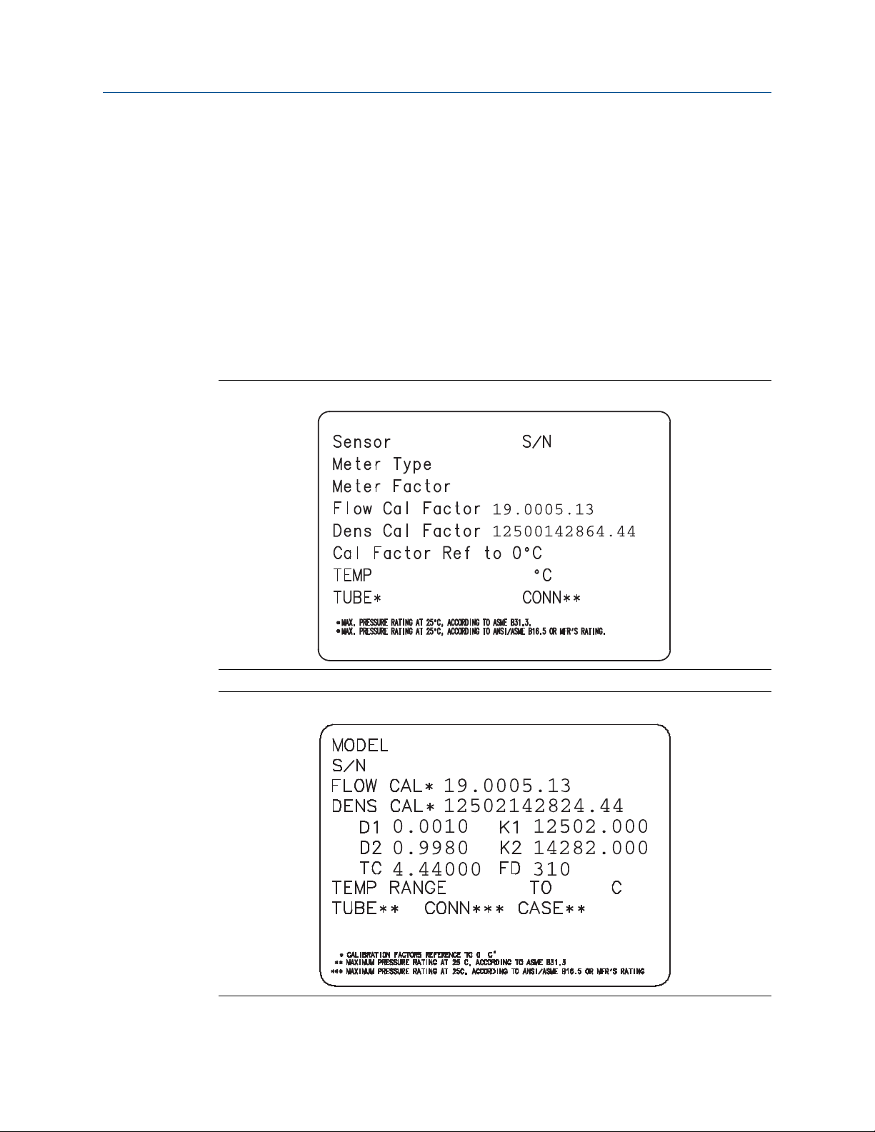
2.4.1 Sample sensor tags
Tag on older curved-tube sensors (all sensors except T-Series)Figure 2-1:
Tag on newer curved-tube sensors (all sensors except T-Series)Figure 2-2:
8 Micro Motion® 9739 MVD Transmitters
Page 17
Quick start
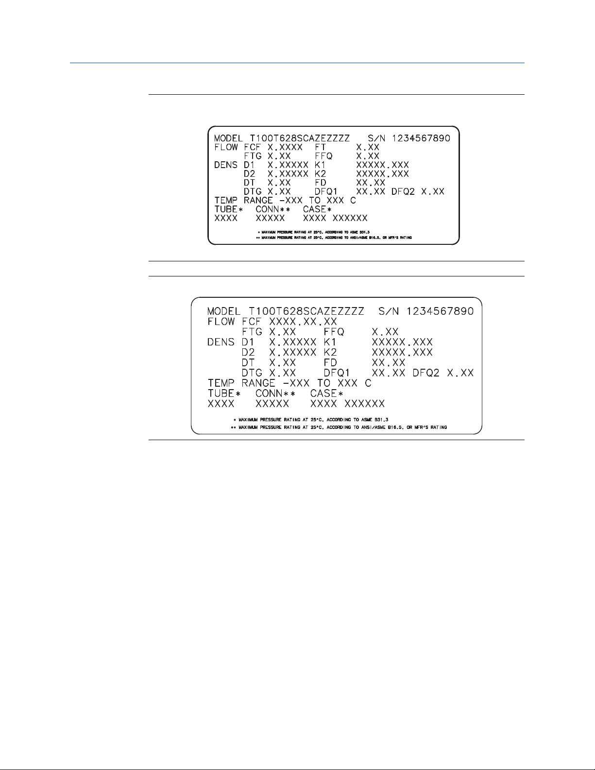
Tag on older straight-tube sensor (T-Series)Figure 2-3:
Tag on newer straight-tube sensor (T-Series)Figure 2-4:
2.4.2 Flow calibration parameters (FCF, FT)
Two separate values are used to describe flow calibration: a 6-character FCF value and a 4character FT value. They are provided on the sensor tag.
Both values contain decimal points. During characterization, these may be entered as two
values or as a single 10-character string. The 10-character string is called either Flowcal or
FCF.
If your sensor tag shows the FCF and the FT values separately and you need to enter a
single value, concatenate the two values to form the single parameter value.
If your sensor tag shows a concatenated Flowcal or FCF value and you need to enter the FCF
and the FT values separately, split the concatenated value:
• FCF = The first 6 characters, including the decimal point
• FT = The last 4 characters, including the decimal point
Configuration and Use Manual 9
Page 18

Quick start
Example: Concatenating FCF and FT
FCF = x.xxxx
FT = y.yy
Flow calibration parameter: x.xxxxy.yy
Example: Splitting the concatenated Flowcal or FCF value
Flow calibration parameter: x.xxxxy.yy
FCF = x.xxxx
FT = y.yy
2.4.3 Density calibration parameters (D1, D2, K1, K2, FD, DT, TC)
Density calibration parameters are typically on the sensor tag and the calibration
certificate.
If your sensor tag does not show a D1 or D2 value:
• For D1, enter the Dens A or D1 value from the calibration certificate. This value is the
line-condition density of the low-density calibration fluid. Micro Motion uses air. If
you cannot find a Dens A or D1 value, enter 0.001 g/cm3.
2.5
• For D2, enter the Dens B or D2 value from the calibration certificate. This value is the
line-condition density of the high-density calibration fluid. Micro Motion uses water.
If you cannot find a Dens B or D2 value, enter 0.998 g/cm3.
If your sensor tag does not show a K1 or K2 value:
• For K1, enter the first 5 digits of the density calibration factor. In the sample tag, this
value is shown as 12500.
• For K2, enter the second 5 digits of the density calibration factor. In the sample tag,
this value is shown as 14286.
If your sensor does not show an FD value, contact Micro Motion customer service.
If your sensor tag does not show a DT or TC value, enter the last 3 digits of the density
calibration factor. In the sample tag, this value is shown as 4.44.
Verify mass flow measurement
Check to see that the mass flow rate reported by the transmitter is accurate. You can use
any available method.
• Read the value for Mass Flow Rate on the transmitter display.
• Connect to the transmitter with ProLink II and read the value for Mass Flow Rate in the
Process Variables window (ProLink > Process Variables).
• Connect to the transmitter with the Field Communicator and read the value for Mass
Flow Rate in the Process Variables menu (On-Line Menu > Overview > Primary Purpose
Variables).
10 Micro Motion® 9739 MVD Transmitters
Page 19

Postrequisites
If the reported mass flow rate is not accurate:
• Check the characterization parameters.
• Review the troubleshooting suggestions for flow measurement issues. See
Section 10.3.
2.6 Verify the zero
Verifying the zero helps you determine if the stored zero value is appropriate to your
installation, or if a field zero can improve measurement accuracy.
The zero verification procedure analyzes the Live Zero value under conditions of zero flow,
and compares it to the Zero Stability range for the sensor. If the average Live Zero value is
within a reasonable range, the zero value stored in the transmitter is valid. Performing a
field calibration will not improve measurement accuracy.
2.6.1 Verify the zero using ProLink II
Quick start
Verifying the zero helps you determine if the stored zero value is appropriate to your
installation, or if a field zero can improve measurement accuracy.
Important
In most cases, the factory zero is more accurate than the field zero. Do not zero the flowmeter unless
one of the following is true:
• The zero is required by site procedures.
• The stored zero value fails the zero verification procedure.
Prerequisites
ProLink II v2.94 or later
Important
Do not verify the zero or zero the flowmeter if a high-severity alarm is active. Correct the problem,
then verify the zero or zero the flowmeter. You may verify the zero or zero the flowmeter if a lowseverity alarm is active.
Procedure
1. Prepare the flowmeter:
a. Allow the flowmeter to warm up for at least 20 minutes after applying power.
b. Run the process fluid through the sensor until the sensor temperature reaches
the normal process operating temperature.
c. Stop flow through the sensor by shutting the downstream valve, and then the
upstream valve if available.
Configuration and Use Manual 11
Page 20

Quick start
d. Verify that the sensor is blocked in, that flow has stopped, and that the sensor is
completely full of process fluid.
2. Choose ProLink > Calibration > Zero Verification and Calibration > Verify Zero and wait until
the procedure completes.
3. If the zero verification procedure fails:
a. Confirm that the sensor is completely blocked in, that flow has stopped, and that
the sensor is completely full of process fluid.
b. Verify that the process fluid is not flashing or condensing, and that it does not
contain particles that can settle out.
c. Repeat the zero verification procedure.
d. If it fails again, zero the flowmeter.
For instructions on zeroing the flowmeter, see Zero the flowmeter.
Postrequisites
Restore normal flow through the sensor by opening the valves.
2.6.2 Terminology used with zero verification and zero
calibration
Terminology used with zero verification and zero calibrationTable 2-2:
Term Definition
Zero In general, the offset required to synchronize the left pickoff and the right pickoff under
conditions of zero flow. Unit = microseconds.
Factory Zero The zero value obtained at the factory, under laboratory conditions.
Field Zero The zero value obtained by performing a zero calibration outside the factory.
Prior Zero The zero value stored in the transmitter at the time a field zero calibration is begun. May
be the factory zero or a previous field zero.
Manual Zero The zero value stored in the transmitter, typically obtained from a zero calibration proce-
dure. It may also be configured manually. Also called “mechanical zero” or “stored zero.”
Live Zero The real-time bidirectional mass flow rate with no flow damping or mass flow cutoff ap-
plied. An adaptive damping value is applied only when the mass flow rate changes dramatically over a very short interval. Unit = configured mass flow measurement unit.
Zero Stability A laboratory-derived value used to calculate the expected accuracy for a sensor. Under
laboratory conditions at zero flow, the average flow rate is expected to fall within the
range defined by the Zero Stability value (0 ± Zero Stability). Each sensor size and model
has a unique Zero Stability value. Statistically, 95% of all data points should fall within the
range defined by the Zero Stability value.
Zero Calibration The procedure used to determine the zero value.
Zero Time The time period over which the Zero Calibration procedure is performed. Unit = seconds.
Field Verification Zero A 3-minute running average of the Live Zero value, calculated by the transmitter. Unit =
configured mass flow measurement unit.
12 Micro Motion® 9739 MVD Transmitters
Page 21

Quick start
Terminology used with zero verification and zero calibration (continued)Table 2-2:
Term Definition
Zero Verification A procedure used to evaluate the stored zero and determine whether or not a field zero
can improve measurement accuracy.
Configuration and Use Manual 13
Page 22

Quick start
14 Micro Motion® 9739 MVD Transmitters
Page 23

Configuration and commissioning
Part II
Configuration and commissioning
Chapters covered in this part:
Introduction to configuration and commissioning
•
Configure process measurement
•
Configure device options and preferences
•
Integrate the meter with the control system
•
Completing the configuration
•
Configuration and Use Manual 15
Page 24

Configuration and commissioning
16 Micro Motion® 9739 MVD Transmitters
Page 25

Introduction to configuration and commissioning
3 Introduction to configuration and
commissioning
Topics covered in this chapter:
Configuration flowchart
•
Default values and ranges
•
Enable access to the off-line menu of the display
•
Disable write-protection on the transmitter configuration
•
HART security
•
Restore the factory configuration
•
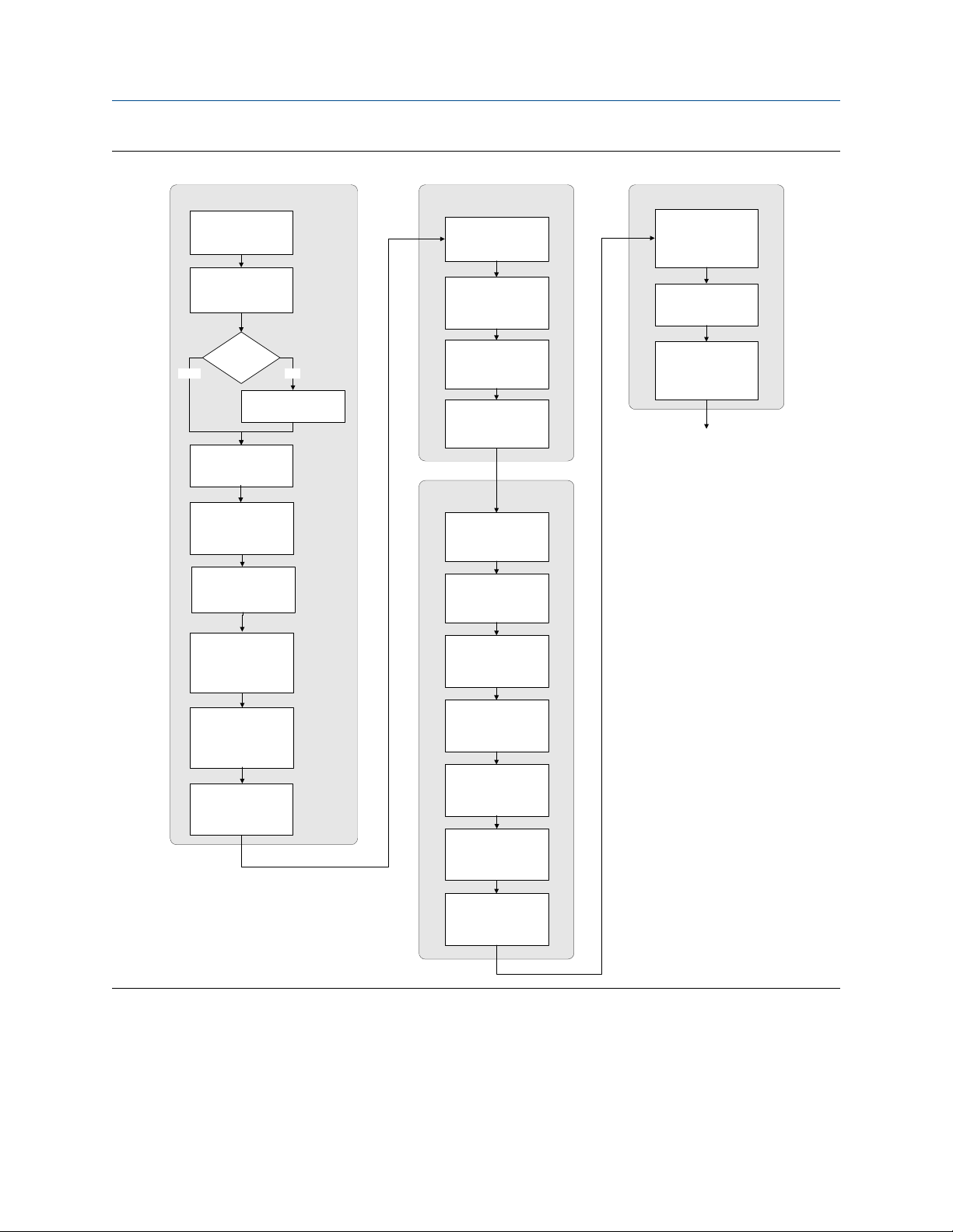
3.1 Configuration flowchart
Use the following flowchart as a general guide to the configuration and commissioning
process.
Some options may not apply to your installation. Detailed information is provided in the
remainder of this manual. If you are using the Weights & Measures application, additional
configuration and setup are required.
Configuration and Use Manual 17
Page 26
Introduction to configuration and commissioning
Configuration flowchartFigure 3-1:
Configure process measurement
Configure mass flow
measurement
Configure volume flow
meaurement
Configure device options and
preferences
Configure display
parameters
Configure fault handling
parameters
Test and move to production
Test or tune transmitter
using sensor simulation
Back up transmitter
configuration
Volume flow type
Liquid
Configure flow direction
Configure density
measurement
Configure temperature
measurement
Configure petroleum
measurement (API)
application (if available)
Configure concentration
measurement application
(if available)
Configure pressure
compensation (optional)
Gas
Define gas properties
Configure sensor
parameters
Configure device
parameters
Integrate device with control system
Configure the mA
output(s)
Configure the frequency
output(s)
Configure the discrete
output(s)
Configure the discrete
input
Configure the mA input
Enable write-protection on
transmitter configuration
Done
Configure events
Configure digital
communications
3.2 Default values and ranges
See Section D.1 to view the default values and ranges for the most commonly used
parameters.
18 Micro Motion® 9739 MVD Transmitters
Page 27
Introduction to configuration and commissioning
3.3 Enable access to the off-line menu of the display
Display OFF-LINE MAINT > OFF-LINE CONFG > DISPLAY > OFFLN
ProLink II ProLink > Configuration > Display > Display Options > Display Offline Menu
Field Communicator
Overview
By default, access to the off-line menu of the display is enabled. If it is disabled, you must
enable it if you want to use the display to configure the transmitter.
Restriction
You cannot use the display to enable access to the off-line menu. You must make a connection from
another tool.
Not available
3.4 Disable write-protection on the transmitter configuration
Display OFF-LINE MAINT > CONFG > LOCK
ProLink II ProLink > Configuration > Device > Enable Write Protection
Not available
3.5
Field Communicator
Overview
If the transmitter is write-protected, the configuration is locked and you must unlock it
before you can change any configuration parameters. By default, the transmitter is not
write-protected.
Tip
Write-protecting the transmitter prevents accidental changes to configuration. It does not prevent
normal operational use. You can always disable write-protection, perform any required configuration
changes, then re-enable write-protection.
HART security
HART security may be enabled on your transmitter. To configure the transmitter using
HART protocol, you must disable HART security.
Configuration and Use Manual 19
Page 28

Introduction to configuration and commissioning
3.6 Restore the factory configuration
Display
ProLink II ProLink > Configuration > Device > Restore Factory Configuration
Field Communicator
Not available
Not available
Overview
Restoring the factory configuration returns the transmitter to a known operational
configuration. This may be useful if you experience problems during configuration.
Tip
Restoring the factory configuration is not a common action. You may want to contact Micro Motion
to see if there is a preferred method to resolve any issues.
20 Micro Motion® 9739 MVD Transmitters
Page 29

Configure process measurement
4 Configure process measurement
Topics covered in this chapter:
Configure mass flow measurement
•
Configure volume flow measurement for liquid applications
•
Configure gas standard volume (GSV) flow measurement
•
Configure Flow Direction
•
Configure density measurement
•
Configure temperature measurement
•
Configure the petroleum measurement application
•
Configure the concentration measurement application
•
Configure pressure compensation
•
4.1 Configure mass flow measurement
The mass flow measurement parameters control how mass flow is measured and reported.
The mass flow measurement parameters include:
Mass Flow Measurement Unit
•
Flow Damping
•
Mass Flow Cutoff
•
4.1.1
Configure Mass Flow Measurement Unit
Display OFF-LINE MAINT > OFF-LINE CONFG > UNITS > MASS
ProLink II ProLink > Configuration > Flow > Mass Flow Units
Field Communicator Configure > Manual Setup > Measurements > Flow > Mass Flow Unit
Overview
Mass Flow Measurement Unit specifies the unit of measure that will be used for the mass flow
rate. The unit used for mass total and mass inventory is derived from this unit.
Procedure
Set Mass Flow Measurement Unit to the unit you want to use.
The default setting for Mass Flow Measurement Unit is g/sec (grams per second).
Configuration and Use Manual 21
Page 30

Configure process measurement
Tip
If the measurement unit you want to use is not available, you can define a special measurement unit.
Options for Mass Flow Measurement Unit
The transmitter provides a standard set of measurement units for Mass Flow Measurement
Unit, plus one user-defined special measurement unit. Different communications tools may
use different labels for the units.
Options for Mass Flow Measurement UnitTable 4-1:
Unit description
Grams per second
Grams per minute
Grams per hour
Kilograms per second
Kilograms per minute
Kilograms per hour
Kilograms per day
Metric tons per minute
Metric tons per hour
Metric tons per day
Pounds per second
Pounds per minute
Pounds per hour
Pounds per day
Short tons (2000 pounds)
per minute
Short tons (2000 pounds)
per hour
Short tons (2000 pounds)
per day
Long tons (2240 pounds)
per hour
Long tons (2240 pounds)
per day
Special unit
Label
Display ProLink II ProLink III Field Communi-
cator
G/S g/sec g/sec g/s
G/MIN g/min g/min g/min
G/H g/hr g/hr g/h
KG/S kg/sec kg/sec kg/s
KG/MIN kg/min kg/min kg/min
KG/H kg/hr kg/hr kg/h
KG/D kg/day kg/day kg/d
T/MIN mTon/min mTon/min MetTon/min
T/H mTon/hr mTon/hr MetTon/h
T/D mTon/day mTon/day MetTon/d
LB/S lbs/sec lbs/sec lb/s
LB/MIN lbs/min lbs/min lb/min
LB/H lbs/hr lbs/hr lb/h
LB/D lbs/day lbs/day lb/d
ST/MIN sTon/min sTon/min STon/min
ST/H sTon/hr sTon/hr STon/h
ST/D sTon/day sTon/day STon/d
LT/H lTon/hr lTon/hr LTon/h
LT/D lTon/day lTon/day LTon/d
SPECL special special Spcl
22 Micro Motion® 9739 MVD Transmitters
Page 31

Configure process measurement
Define a special measurement unit for mass flow
Display
ProLink II ProLink > Configuration > Special Units
Field Communicator Configure > Manual Setup > Measurements > Special Units > Mass Special Units
Not available
Overview
A special measurement unit is a user-defined unit of measure that allows you to report
process data, totalizer data, and inventory data in a unit that is not available in the
transmitter. A special measurement unit is calculated from an existing measurement unit
using a conversion factor.
Note
Although you cannot define a special measurement unit using the display, you can use the display to
select an existing special measurement unit, and to view process data using the special
measurement unit.
Procedure
1. Specify Base Mass Unit.
Base Mass Unit is the existing mass unit that the special unit will be based on.
2. Specify Base Time Unit.
Base Time Unit is the existing time unit that the special unit will be based on.
3. Calculate Mass Flow Conversion Factor as follows:
a. x base units = y special units
b. Mass Flow Conversion Factor = x/y
4. Enter Mass Flow Conversion Factor.
5. Set Mass Flow Label to the name you want to use for the mass flow unit.
6. Set Mass Total Label to the name you want to use for the mass total and mass
inventory unit.
The special measurement unit is stored in the transmitter. You can configure the
transmitter to use the special measurement unit at any time.
Example: Defining a special measurement unit for mass flow
You want to measure mass flow in ounces per second (oz/sec).
1. Set Base Mass Unit to Pounds (lb).
2. Set Base Time Unit to Seconds (sec).
3. Calculate Mass Flow Conversion Factor:
a. 1 lb/sec = 16 oz/sec
Configuration and Use Manual 23
Page 32

Configure process measurement
b. Mass Flow Conversion Factor = 1/16 = 0.0625
4. Set Mass Flow Conversion Factor to 0.0625.
5. Set Mass Flow Label to oz/sec.
6. Set Mass Total Label to oz.
4.1.2 Configure Flow Damping
Display
ProLink II ProLink > Configuration > Flow > Flow Damp
Field Communicator Configure > Manual Setup > Measurements > Flow > Flow Damping
Not available
Overview
Damping is used to smooth out small, rapid fluctuations in process measurement. Damping
Value specifies the time period (in seconds) over which the transmitter will spread changes
in the reported process variable. At the end of the interval, the reported process variable
will reflect 63% of the change in the actual measured value.
Procedure
Set Flow Damping to the value you want to use.
The default value is 0.8 seconds. The range is 0 to 10.24 seconds.
Tips
• A high damping value makes the process variable appear smoother because the reported value
changes slowly.
• A low damping value makes the process variable appear more erratic because the reported value
changes more quickly.
• The combination of a high damping value and rapid, large changes in flow rate can result in
increased measurement error.
• Whenever the damping value is non-zero, the reported measurement will lag the actual
measurement because the reported value is being averaged over time.
• In general, lower damping values are preferable because there is less chance of data loss, and less
lag time between the actual measurement and the reported value.
• Micro Motion recommends using the default value of 0.04 seconds.
The value you enter is automaticaly rounded down to the nearest valid value. The valid
values for Flow Damping are: 0, 0.04, 0.08, 0.16, ... 10.24.
Effect of Flow Damping on volume measurement
Flow Damping affects volume measurement for liquid volume data. Flow Damping also affects
volume measurement for gas standard volume data. The transmitter calculates volume
data from the damped mass flow data.
24 Micro Motion® 9739 MVD Transmitters
Page 33

Interaction between Flow Damping and Added Damping
In some circumstances, both Flow Damping and Added Damping are applied to the reported
mass flow value.
Flow Damping controls the rate of change in flow process variables. Added Damping controls
the rate of change reported via the mA output. If mA Output Process Variable is set to Mass
Flow Rate, and both Flow Damping and Added Damping are set to non-zero values, flow
damping is applied first, and the added damping calculation is applied to the result of the
first calculation.
4.1.3 Configure Mass Flow Cutoff
Configure process measurement
Display
ProLink II ProLink > Configuration > Flow > Mass Flow Cutoff
Field Communicator Configure > Manual Setup > Measurements > Flow > Mass Flow Cutoff
Overview
Mass Flow Cutoff specifies the lowest mass flow rate that will be reported as measured. All
mass flow rates below this cutoff will be reported as 0.
Procedure
Set Mass Flow Cutoff to the value you want to use.
The default value for Mass Flow Cutoff is 0.0 g/sec or a sensor-specific value set at the
factory. The recommended setting is 0.05% of the sensor's rated maximum flow rate or a
value below the highest expected flow rate. Do not set Mass Flow Cutoff to 0.0 g/sec.
Not available
Effect of Mass Flow Cutoff on volume measurement
Mass Flow Cutoff does not affect volume measurement. Volume data is calculated from the
actual mass data rather than the reported value.
Interaction between Mass Flow Cutoff and AO Cutoff
Mass Flow Cutoff defines the lowest mass flow value that the transmitter will report as
measured. AO Cutoff defines the lowest flow rate that will be reported via the mA output. If
mA Output Process Variable is set to Mass Flow Rate, the mass flow rate reported via the mA
output is controlled by the higher of the two cutoff values.
Mass Flow Cutoff affects all reported values and values used in other transmitter behavior
(e.g., events defined on mass flow).
AO Cutoff affects only mass flow values reported via the mA output.
Configuration and Use Manual 25
Page 34

Configure process measurement
Example: Cutoff interaction with AO Cutoff lower than Mass Flow Cutoff
Configuration:
• mA Output Process Variable: Mass Flow Rate
• Frequency Output Process Variable: Mass Flow Rate
• AO Cutoff: 10 g/sec
• Mass Flow Cutoff: 15 g/sec
Result: If the mass flow rate drops below 15 g/sec, mass flow will be reported as 0, and 0
will be used in all internal processing.
Example: Cutoff interaction with AO Cutoff higher than Mass Flow Cutoff
Configuration:
• mA Output Process Variable: Mass Flow Rate
• Frequency Output Process Variable: Mass Flow Rate
• AO Cutoff: 15 g/sec
• Mass Flow Cutoff: 10 g/sec
4.2
Result:
• If the mass flow rate drops below 15 g/sec but not below 10 g/sec:
- The mA output will report zero flow.
- The frequency output will report the actual flow rate, and the actual flow rate will
be used in all internal processing.
• If the mass flow rate drops below 10 g/sec, both outputs will report zero flow, and 0
will be used in all internal processing.
Configure volume flow measurement for liquid applications
The volume flow measurement parameters control how liquid volume flow is measured
and reported.
The volume flow measurement parameters include:
Volume Flow Type
•
Volume Flow Measurement Unit
•
Volume Flow Cutoff
•
Restriction
You cannot implement both liquid volume flow and gas standard volume flow at the same time. You
must choose one or the other.
26 Micro Motion® 9739 MVD Transmitters
Page 35

Configure process measurement
4.2.1 Configure Volume Flow Type for liquid applications
Display OFF-LINE MAINT > OFF-LINE CONFG > VOL > VOL TYPE LIQUID
ProLink II ProLink > Configuration > Flow > Vol Flow Type > Liquid Volume
Field Communicator Configure > Manual Setup > Measurements > Gas Standard Volume > Volume Flow Type > Liquid
Overview
Volume Flow Type controls whether liquid or gas standard volume flow measurement will be
used.
Restriction
If you are using the petroleum measurement application, you must set Volume Flow Type to Liquid. Gas
standard volume measurement is incompatible with the petroleum measurement application.
Restriction
If you are using the concentration measurement application, you must set Volume Flow Type to Liquid.
Gas standard volume measurement is incompatible with the concentration measurement
application.
4.2.2
Procedure
Set Volume Flow Type to Liquid.
Configure Volume Flow Measurement Unit for liquid applications
Display OFF-LINE MAINT > OFF-LINE CONFG > UNITS > VOL
ProLink II ProLink > Configuration > Flow > Vol Flow Units
Field Communicator Configure > Manual Setup > Measurements > Flow > Volume Flow Unit
Overview
Volume Flow Measurement Unit specifies the unit of measurement that will be displayed for the
volume flow rate. The unit used for the volume total and volume inventory is based on this
unit.
Prerequisites
Before you configure Volume Flow Measurement Unit, be sure that Volume Flow Type is set to
Liquid.
Procedure
Set Volume Flow Measurement Unit to the unit you want to use.
Configuration and Use Manual 27
Page 36

Configure process measurement
The default setting for Volume Flow Measurement Unit is l/sec (liters per second).
Tip
If the measurement unit you want to use is not available, you can define a special measurement unit.
Options for Volume Flow Measurement Unit for liquid applications
The transmitter provides a standard set of measurement units for Volume Flow Measurement
Unit, plus one user-defined measurement unit. Different communications tools may use
different labels for the units.
Options for Volume Flow Measurement Unit for liquid applicationsTable 4-2:
Unit description
Cubic feet per second
Cubic feet per minute
Cubic feet per hour
Cubic feet per day
Cubic meters per second
Cubic meters per minute M3/MIN
Cubic meters per hour
Cubic meters per day
U.S. gallons per second
U.S. gallons per minute
U.S. gallons per hour
U.S. gallons per day
Million U.S. gallons per day
Liters per second
Liters per minute L/MIN
Liters per hour
Million liters per day
Imperial gallons per second
Imperial gallons per minute
Imperial gallons per hour
Imperial gallons per day
Barrels per second
(1)
Display ProLink II ProLink III Field Communica-
CUFT/S ft3/sec ft3/sec Cuft/s
CUF/MN ft3/min ft3/min Cuft/min
CUFT/H ft3/hr ft3/hr Cuft/h
CUFT/D ft3/day ft3/day Cuft/d
M3/S m3/sec m3/sec Cum/s
M3/H m3/hr m3/hr Cum/h
M3/D m3/day m3/day Cum/d
USGPS US gal/sec US gal/sec gal/s
USGPM US gal/min US gal/min gal/min
USGPH US gal/hr US gal/hr gal/h
USGPD US gal/day US gal/day gal/d
MILG/D mil US gal/day mil US gal/day MMgal/d
L/S l/sec l/sec L/s
L/H l/hr l/hr L/h
MILL/D mil l/day mil l/day ML/d
UKGPS Imp gal/sec Imp gal/sec Impgal/s
UKGPM Imp gal/min Imp gal/min Impgal/min
UKGPH Imp gal/hr Imp gal/hr Impgal/h
UKGPD Imp gal/day Imp gal/day Impgal/d
BBL/S barrels/sec barrels/sec bbl/s
Label
tor
m3/min m3/min Cum/min
l/min l/min L/min
(1) Unit based on oil barrels (42 U.S. gallons).
28 Micro Motion® 9739 MVD Transmitters
Page 37

Options for Volume Flow Measurement Unit for liquid applications (continued)Table 4-2:
Unit description
Barrels per minute
Barrels per hour
Barrels per day
(1)
(1)
(1)
Beer barrels per second
Beer barrels per minute
Beer barrels per hour
Beer barrels per day
(2)
(2)
Special unit
Define a special measurement unit for volume flow
(2)
(2)
Configure process measurement
Label
Display ProLink II ProLink III Field Communica-
tor
BBL/MN barrels/min barrels/min bbl/min
BBL/H barrels/hr barrels/hr bbl/h
BBL/D barrels/day barrels/day bbl/d
BBBL/S Beer barrels/sec Beer barrels/sec bbbl/s
BBBL/MN Beer barrels/min Beer barrels/min bbbl/min
BBBL/H Beer barrels/hr Beer barrels/hr bbbl/h
BBBL/D Beer barrels/day Beer barrels/day bbbl/d
SPECL special special Spcl
Display
ProLink II ProLink > Configuration > Special Units
Field Communicator Configure > Manual Setup > Measurements > Special Units > Volume Special Units
Not available
Overview
A special measurement unit is a user-defined unit of measure that allows you to report
process data, totalizer data, and inventory data in a unit that is not available in the
transmitter. A special measurement unit is calculated from an existing measurement unit
using a conversion factor.
Note
Although you cannot define a special measurement unit using the display, you can use the display to
select an existing special measurement unit, and to view process data using the special
measurement unit.
Procedure
1. Specify Base Volume Unit.
Base Volume Unit is the existing volume unit that the special unit will be based on.
2. Specify Base Time Unit.
Base Time Unit is the existing time unit that the special unit will be based on.
3. Calculate Volume Flow Conversion Factor as follows:
(2) Unit based on U.S. beer barrels (31 U.S. gallons).
Configuration and Use Manual 29
Page 38

Configure process measurement
4. Enter Volume Flow Conversion Factor.
5. Set Volume Flow Label to the name you want to use for the volume flow unit.
6. Set Volume Total Label to the name you want to use for the volume total and volume
The special measurement unit is stored in the transmitter. You can configure the
transmitter to use the special measurement unit at any time.
Example: Defining a special measurement unit for volume flow
You want to measure volume flow in pints per second (pints/sec).
1. Set Base Volume Unit to Gallons (gal).
2. Set Base Time Unit to Seconds (sec).
3. Calculate the conversion factor:
a. x base units = y special units
b. Volume Flow Conversion Factor = x/y
inventory unit.
a. 1 gal/sec = 8 pints/sec
b. Volume Flow Conversion Factor = 1/8 = 0.1250
4.2.3
4. Set Volume Flow Conversion Factor to 0.1250.
5. Set Volume Flow Label to pints/sec.
6. Set Volume Total Label to pints.
Configure Volume Flow Cutoff
Display
ProLink II ProLink > Configuration > Flow > Vol Flow Cutoff
Field Communicator Configure > Manual Setup > Measurements > Flow > Volume Flow Cutoff
Overview
Volume Flow Cutoff specifies the lowest volume flow rate that will be reported as measured.
All volume flow rates below this cutoff are reported as 0.
Procedure
Set Volume Flow Cutoff to the value you want to use.
The default value for Volume Flow Cutoff is 0.0 l/sec (liters per second). The lower limit is 0.
The upper limit is the sensor’s flow calibration factor, in units of l/sec, multiplied by 0.2.
Not available
30 Micro Motion® 9739 MVD Transmitters
Page 39

Configure process measurement
Interaction between Volume Flow Cutoff and AO Cutoff
Volume Flow Cutoff defines the lowest liquid volume flow value that the transmitter will
report as measured. AO Cutoff defines the lowest flow rate that will be reported via the mA
output. If mA Output Process Variable is set to Volume Flow Rate, the volume flow rate reported
via the mA output is controlled by the higher of the two cutoff values.
Volume Flow Cutoff affects both the volume flow values reported via the outputs and the
volume flow values used in other transmitter behavior (e.g., events defined on the volume
flow).
AO Cutoff affects only flow values reported via the mA output.
Example: Cutoff interaction with AO Cutoff lower than Volume Flow Cutoff
Configuration:
• mA Output Process Variable: Volume Flow Rate
• Frequency Output Process Variable: Volume Flow Rate
• AO Cutoff: 10 l/sec
• Volume Flow Cutoff: 15 l/sec
Result: If the volume flow rate drops below 15 l/sec, volume flow will be reported as 0, and
0 will be used in all internal processing.
Example: Cutoff interaction with AO Cutoff higher than Volume Flow Cutoff
Configuration:
• mA Output Process Variable: Volume Flow Rate
• Frequency Output Process Variable: Volume Flow Rate
• AO Cutoff: 15 l/sec
• Volume Flow Cutoff: 10 l/sec
Result:
• If the volume flow rate drops below 15 l/sec but not below 10 l/sec:
- The mA output will report zero flow.
- The frequency output will report the actual flow rate, and the actual flow rate will
be used in all internal processing.
• If the volume flow rate drops below 10 l/sec, both outputs will report zero flow, and
0 will be used in all internal processing.
4.3
Configure gas standard volume (GSV) flow measurement
The gas standard volume (GSV) flow measurement parameters control how gas standard
volume flow is measured and reported.
Configuration and Use Manual 31
Page 40

Configure process measurement
The GSV flow measurement parameters include:
Volume Flow Type
•
Standard Gas Density
•
Gas Standard Volume Flow Measurement Unit
•
Gas Standard Volume Flow Cutoff
•
Restriction
You cannot implement both liquid volume flow and gas standard volume flow at the same time. You
must choose one or the other.
4.3.1 Configure Volume Flow Type for gas applications
Display OFF-LINE MAINT > OFF-LINE CONFG > VOL > VOL TYPE GAS
ProLink II ProLink > Configuration > Flow > Vol Flow Type > Std Gas Volume
Field Communicator Configure > Manual Setup > Measurements > Gas Standard Volume > Volume Flow Type > GSV
4.3.2
Overview
Volume Flow Type controls whether liquid or gas standard volume flow measurement is
used.
Procedure
Set Volume Flow Type to Gas Standard Volume.
Configure Standard Gas Density
Display
ProLink II ProLink > Configuration > Flow > Std Gas Density
Field Communicator Configure > Manual Setup > Measurements > Gas Standard Volume > Gas Density
Overview
The Standard Gas Density value is used to convert the measured flow data to the standard
reference values.
Prerequisites
Ensure that Density Measurement Unit is set to the measurement unit you want to use for
Standard Gas Density.
Not available
Procedure
Set Standard Gas Density to the standard reference density of the gas you are measuring.
32 Micro Motion® 9739 MVD Transmitters
Page 41

Configure process measurement
Note
ProLink II and ProLink III provide a guided method that you can use to calculate the standard density
of your gas, if you do not know it.
4.3.3 Configure Gas Standard Volume Flow Measurement Unit
Display OFF-LINE MAINT > OFF-LINE CONFG > UNITS > VOL
ProLink II ProLink > Configuration > Flow > Std Gas Vol Flow Units
Field Communicator Configure > Manual Setup > Measurements > Gas Standard Volume > Gas Vol Flow Unit
Overview
Gas Standard Volume Flow Measurement Unit specifies the unit of measure that will be displayed
for the gas standard volume flow rate. The measurement unit used for the gas standard
volume total and the gas standard volume inventory is derived from this unit.
Prerequisites
Before you configure Gas Standard Volume Flow Measurement Unit, be sure that Volume Flow Type
is set to Gas Standard Volume.
Procedure
Set Gas Standard Volume Flow Measurement Unit to the unit you want to use.
The default setting for Gas Standard Volume Flow Measurement Unit is SCFM (Standard Cubic
Feet per Minute).
Tip
If the measurement unit you want to use is not available, you can define a special measurement unit.
Options for Gas Standard Volume Flow Measurement Unit
The transmitter provides a standard set of measurement units for Gas Standard Volume Flow
Measurement Unit, plus one user-defined special measurement unit. Different
communications tools may use different labels for the units.
Options for Gas Standard Volume Measurement UnitTable 4-3:
Unit description
Normal cubic meters per second
Normal cubic meters per minute
Label
Display ProLink II ProLink III Field Communica-
tor
NM3/S Nm3/sec Nm3/sec Nm3/sec
NM3/MN Nm3/min Nm3/sec Nm3/min
Configuration and Use Manual 33
Page 42

Configure process measurement
Options for Gas Standard Volume Measurement Unit (continued)Table 4-3:
Unit description
Normal cubic meters per hour
Normal cubic meters per day
Normal liter per second
Normal liter per minute
Normal liter per hour
Normal liter per day
Standard cubic feet per second
Standard cubic feet per minute
Standard cubic feet per hour
Standard cubic feet per day
Standard cubic meters per second
Standard cubic meters per minute
Standard cubic meters per
hour
Standard cubic meters per day
Standard liter per second
Standard liter per minute
Standard liter per hour
Standard liter per day
Special measurement unit
Label
Display ProLink II ProLink III Field Communica-
tor
NM3/H Nm3/hr Nm3/hr Nm3/hr
NM3/D Nm3/day Nm3/day Nm3/day
NLPS NLPS NLPS NLPS
NLPM NLPM NLPM NLPM
NLPH NLPH NLPH NLPH
NLPD NLPD NLPD NLPD
SCFS SCFS SCFS SCFS
SCFM SCFM SCFM SCFM
SCFH SCFH SCFH SCFH
SCFD SCFD SCFD SCFD
SM3/S Sm3/S Sm3/sec Sm3/sec
SM3/MN Sm3/min Sm3/min Sm3/min
SM3/H Sm3/hr Sm3/hr Sm3/hr
SM3/D Sm3/day Sm3/day Sm3/day
SLPS SLPS SLPS SLPS
SLPM SLPM SLPM SLPM
SLPH SLPH SLPH SLPH
SLPD SLPD SLPD SLPD
SPECL special special Special
Define a special measurement unit for gas standard volume flow
Display
ProLink II ProLink > Configuration > Special Units
Field Communicator Configure > Manual Setup > Measurements > Special Units > Volume Special Units
34 Micro Motion® 9739 MVD Transmitters
Not available
Page 43

Configure process measurement
Overview
A special measurement unit is a user-defined unit of measure that allows you to report
process data, totalizer data, and inventory data in a unit that is not available in the
transmitter. A special measurement unit is calculated from an existing measurement unit
using a conversion factor.
Note
Although you cannot define a special measurement unit using the display, you can use the display to
select an existing special measurement unit, and to view process data using the special
measurement unit.
Procedure
1. Specify Base Gas Standard Volume Unit.
Base Gas Standard Volume Unit is the existing gas standard volume unit that the special
unit will be based on.
2. Specify Base Time Unit.
Base Time Unit is the existing time unit that the special unit will be based on.
3. Calculate Gas Standard Volume Flow Conversion Factor as follows:
a. x base units = y special units
b. Gas Standard Volume Flow Conversion Factor = x/y
4. Enter the Gas Standard Volume Flow Conversion Factor.
5. Set Gas Standard Volume Flow Label to the name you want to use for the gas standard
volume flow unit.
6. Set Gas Standard Volume Total Label to the name you want to use for the gas standard
volume total and gas standard volume inventory unit.
The special measurement unit is stored in the transmitter. You can configure the
transmitter to use the special measurement unit at any time.
Example: Defining a special measurement unit for gas standard volume flow
You want to measure gas standard volume flow in thousands of standard cubic feet per
minute.
1. Set Base Gas Standard Volume Unit to SCFM.
2. Set Base Time Unit to minutes (min).
3. Calculate the conversion factor:
a. 1 thousands of standard cubic feet per minute = 1000 cubic feet per minute
b. Gas Standard Volume Flow Conversion Factor = 1/1000 = 0.001
4. Set Gas Standard Volume Flow Conversion Factor to 0.001.
5. Set Gas Standard Volume Flow Label to KSCFM.
6. Set Gas Standard Volume Total Label to KSCF.
Configuration and Use Manual 35
Page 44

Configure process measurement
4.3.4 Configure Gas Standard Volume Flow Cutoff
Display
ProLink II ProLink > Configuration > Flow > Std Gas Vol Flow Cutoff
Field Communicator Configure > Manual Setup > Measurements > Gas Standard Volume > GSV Cutoff
Overview
Gas Standard Volume Flow Cutoff specifies the lowest gas standard volume flow rate that will
reported as measured. All gas standard volume flow rates below this cutoff will be
reported as 0.
Procedure
Set Gas Standard Volume Flow Cutoff to the value you want to use.
The default value for Gas Standard Volume Flow Cutoff is 0.0. The lower limit is 0.0. There is no
upper limit.
Not available
Interaction between Gas Standard Volume Flow Cutoff and AO Cutoff
Gas Standard Volume Flow Cutoff defines the lowest Gas Standard Volume flow value that the
transmitter will report as measured. AO Cutoff defines the lowest flow rate that will be
reported via the mA output. If mA Output Process Variable is set to Gas Standard Volume Flow
Rate, the volume flow rate reported via the mA output is controlled by the higher of the
two cutoff values.
Gas Standard Volume Flow Cutoff affects both the gas standard volume flow values reported
via outputs and the gas standard volume flow values used in other transmitter behavior
(e.g., events defined on gas standard volume flow).
AO Cutoff affects only flow values reported via the mA output.
Example: Cutoff interaction with AO Cutoff lower than Gas Standard Volume Flow
Cutoff
Configuration:
• mA Output Process Variable for the primary mA output: Gas Standard Volume Flow Rate
• Frequency Output Process Variable: Gas Standard Volume Flow Rate
• AO Cutoff for the primary mA output: 10 SLPM (standard liters per minute)
• Gas Standard Volume Flow Cutoff: 15 SLPM
Result: If the gas standard volume flow rate drops below 15 SLPM, the volume flow will be
reported as 0, and 0 will be used in all internal processing.
36 Micro Motion® 9739 MVD Transmitters
Page 45

Configure process measurement
Example: Cutoff interaction with AO Cutoff higher than Gas Standard Volume Flow
Cutoff
Configuration:
• mA Output Process Variable for the primary mA output: Gas Standard Volume Flow Rate
• Frequency Output Process Variable: Gas Standard Volume Flow Rate
• AO Cutoff for the primary mA output: 15 SLPM (standard liters per minute)
• Gas Standard Volume Flow Cutoff: 10 SLPM
Result:
• If the gas standard volume flow rate drops below 15 SLPM but not below 10 SLPM:
- The primary mA output will report zero flow.
- The frequency output will report the actual flow rate, and the actual flow rate will
be used in all internal processing.
• If the gas standard volume flow rate drops below 10 SLPM, both outputs will report
zero flow, and 0 will be used in all internal processing.
4.4 Configure Flow Direction
Display
ProLink II ProLink > Configuration > Flow > Flow Direction
Field Communicator Configure > Manual Setup > Measurements > Flow > Flow Direction
Overview
Flow Direction controls how forward flow and reverse flow affect flow measurement and
reporting.
Flow Direction is defined with respect to the flow arrow on the sensor:
• Forward flow (positive flow) moves in the direction of the flow arrow on the sensor.
• Reverse flow (negative flow) moves in the direction opposite to the flow arrow on
the sensor.
Tip
Micro Motion sensors are bidirectional. Measurement accuracy is not affected by actual flow
direction or the setting of the Flow Direction parameter.
Procedure
Not available
Set Flow Direction to the value you want to use.
Configuration and Use Manual 37
Page 46

Configure process measurement
4.4.1 Options for Flow Direction
Options for Flow DirectionTable 4-4:
Flow Direction setting Relationship to Flow Direction ar-
ProLink II ProLink III Field Communicator
row on sensor
Forward Forward Forward
Reverse Reverse Reverse
Absolute Value Absolute Value Absolute Value
Bidirectional Bidirectional Bi directional
Negate Forward Negate Forward Negate/Forward Only
Negate Bidirectional Negate Bidirectional Negate/Bi-directional
Effect of Flow Direction on mA outputs
Appropriate when the Flow Direction
arrow is in the same direction as the
majority of flow.
Appropriate when the Flow Direction
arrow is in the same direction as the
majority of flow.
Flow Direction arrow is not relevant.
Appropriate when both forward and
reverse flow are expected, and forward flow will dominate, but the
amount of reverse flow will be significant.
Appropriate when the Flow Direction
arrow is in the opposite direction from
the majority of flow.
Appropriate when both forward and
reverse flow are expected, and reverse
flow will dominate, but the amount of
forward flow will be significant.
Flow Direction affects how the transmitter reports flow values via the mA outputs. The mA
outputs are affected by Flow Direction only if mA Output Process Variable is set to a flow
variable.
Flow Direction and mA outputs
The effect of Flow Direction on the mA outputs depend on Lower Range Value configured for
the mA output:
• If Lower Range Value is set to 0, see Figure 4-1.
• If Lower Range Value is set to a negative value, see Figure 4-2.
38 Micro Motion® 9739 MVD Transmitters
Page 47

Configure process measurement
Effect of Flow Direction on the mA output: Lower Range Value = 0Figure 4-1:
Flow Direction = Forward
20
12
mA output
4
-x 0 x
Reverse flow Forward flow
• Lower Range Value = 0
• Upper Range Value = x
Effect of Flow Direction on the mA output: Lower Range Value < 0Figure 4-2:
Flow Direction = Forward
20
Flow Direction = Reverse, Negate Forward
20
12
mA output
4
-x 0 x
Reverse flow Forward flow
Flow Direction = Reverse, Negate Forward
20
Flow Direction = Absolute Value, Bidirectional,
Negate Bidirectional
20
12
mA output
4
-x 0 x
Reverse flow Forward flow
Flow Direction = Absolute Value, Bidirectional,
Negate Bidirectional
20
12
mA output
4
-x 0 x
Reverse flow Forward flow
• Lower Range Value = −x
• Upper Range Value = x
Example: Flow Direction = Forward and Lower Range Value = 0
Configuration:
• Flow Direction = Forward
• Lower Range Value = 0 g/sec
• Upper Range Value = 100 g/sec
Result:
12
mA output
4
-x 0 x
Reverse flow Forward flow
12
mA output
4
-x 0 x
Reverse flow Forward flow
Configuration and Use Manual 39
Page 48

Configure process measurement
• Under conditions of reverse flow or zero flow, the mA output is 4 mA.
• Under conditions of forward flow, up to a flow rate of 100 g/sec, the mA output
• Under conditions of forward flow, if the flow rate equals or exceeds 100 g/sec, the
Example: Flow Direction = Forward and Lower Range Value < 0
Configuration:
• Flow Direction = Forward
• Lower Range Value = −100 g/sec
• Upper Range Value = +100 g/sec
Result:
• Under conditions of zero flow, the mA output is 12 mA.
• Under conditions of forward flow, for flow rates between 0 and +100 g/sec, the mA
• Under conditions of forward flow, if (the absolute value of) the flow rate equals or
• Under conditions of reverse flow, for flow rates between 0 and −100 g/sec, the mA
• Under conditions of reverse flow, if the absolute value of the flow rate equals or
varies between 4 mA and 20 mA in proportion to the flow rate.
mA output will be proportional to the flow rate up to 20.5 mA, and will be level at
20.5 mA at higher flow rates.
output varies between 12 mA and 20 mA in proportion to (the absolute value of) the
flow rate.
exceeds 100 g/sec, the mA output is proportional to the flow rate up to 20.5 mA,
and will be level at 20.5 mA at higher flow rates.
output varies between 4 mA and 12 mA in inverse proportion to the absolute value
of the flow rate.
exceeds 100 g/sec, the mA output is inversely proportional to the flow rate down to
3.8 mA, and will be level at 3.8 mA at higher absolute values.
Example: Flow Direction = Reverse
Configuration:
• Flow Direction = Reverse
• Lower Range Value = 0 g/sec
• Upper Range Value = 100 g/sec
Result:
• Under conditions of forward flow or zero flow, the mA output is 4 mA.
• Under conditions of reverse flow, for flow rates between 0 and +100 g/sec, the mA
output level varies between 4 mA and 20 mA in proportion to the absolute value of
the flow rate.
• Under conditions of reverse flow, if the absolute value of the flow rate equals or
exceeds 100 g/sec, the mA output will be proportional to the absolute value of the
flow rate up to 20.5 mA, and will be level at 20.5 mA at higher absolute values.
40 Micro Motion® 9739 MVD Transmitters
Page 49

Configure process measurement
Effect of Flow Direction on frequency outputs
Flow Direction affects how the transmitter reports flow values via the frequency outputs. The
frequency outputs are affected by Flow Direction only if Frequency Output Process Variable is set
to a flow variable.
Table 4-5:
Effect of the Flow Direction parameter and actual flow direction on
frequency outputs
Flow Direction setting Actual flow direction
Forward Zero flow Reverse
Forward
Reverse
Bidirectional
Absolute Value
Negate Forward
Negate Bidirectional
Hz > 0 0 Hz 0 Hz
0 Hz 0 Hz Hz > 0
Hz > 0 0 Hz Hz > 0
Hz > 0 0 Hz Hz > 0
0 Hz 0 Hz Hz > 0
Hz > 0 0 Hz Hz > 0
Effect of Flow Direction on discrete outputs
The Flow Direction parameter affects the discrete output behavior only if Discrete Output
Source is set to Flow Direction.
Table 4-6:
Flow Direction setting Actual flow direction
Effect of the Flow Direction parameter and actual flow direction on
discrete outputs
Forward Zero flow Reverse
Forward
Reverse
Bidirectional
Absolute Value
Negate Forward
Negate Bidirectional
OFF OFF ON
OFF OFF ON
OFF OFF ON
OFF OFF OFF
ON OFF OFF
ON OFF OFF
Effect of Flow Direction on digital communications
Flow Direction affects how flow values are reported via digital communications.
Configuration and Use Manual 41
Page 50

Configure process measurement
Table 4-7:
Effect of the Flow Direction parameter and actual flow direction on flow
values reported via digital communications
Flow Direction setting Actual flow direction
Forward Zero flow Reverse
Forward
Reverse
Bidirectional
Absolute Value
Negate Forward
Negate Bidirectional
Positive 0 Negative
Positive 0 Negative
Positive 0 Negative
Positive
Negative 0 Positive
Negative 0 Positive
(3)
0 Positive
Effect of Flow Direction on flow totals
Flow Direction affects how flow totals and inventories are calculated.
Table 4-8:
Flow Direction setting Actual flow direction
Effect of the Flow Direction parameter and actual flow direction on flow
totals and inventories
Forward Zero flow Reverse
Forward
Reverse
Bidirectional
Absolute Value
Negate Forward
Negate Bidirectional
Totals increase Totals do not change Totals do not change
Totals do not change Totals do not change Totals increase
Totals increase Totals do not change Totals decrease
Totals increase Totals do not change Totals increase
Totals do not change Totals do not change Totals increase
Totals decrease Totals do not change Totals increase
4.5 Configure density measurement
The density measurement parameters control how density is measured and reported.
Density measurement (along with mass measurement) is used to determine liquid volume
flow.
The density measurement parameters include:
Density Measurement Unit
•
Slug Flow Parameters
•
Density Damping
•
Density Cutoff
•
(3) Refer to the digital communications status bits for an indication of whether flow is positive or negative.
42 Micro Motion® 9739 MVD Transmitters
Page 51

4.5.1 Configure Density Measurement Unit
Display OFF-LINE MAINT > OFF-LINE CONFG > UNITS > DENS
ProLink II ProLink > Configuration > Density > Density Units
Field Communicator Configure > Manual Setup > Measurements > Density > Density Unit
Overview
Density Measurement Unit specifies the units of measure that will be displayed for density
measurement.
Procedure
Set Density Measurement Unit to the option you want to use.
The default setting for Density Measurement Unit is g/cm3 (grams per cubic centimeter).
Options for Density Measurement Unit
Configure process measurement
The transmitter provides a standard set of measurement units for Density Measurement Unit.
Different communications tools may use different labels.
Options for Density Measurement UnitTable 4-9:
Unit description
Specific gravity unit (not temperature-corrected)
Grams per cubic centimeter
Grams per liter
Grams per milliliter
Kilograms per liter
Kilograms per cubic meter
Pounds per U.S. gallon
Pounds per cubic foot
Pounds per cubic inch
API gravity
Short ton per cubic yard
Label
Display ProLink II ProLink III Field Communica-
tor
SGU SGU SGU SGU
G/CM3 g/cm3 g/cm3 g/Cucm
G/L g/l g/l g/L
G/mL g/ml g/ml g/mL
KG/L kg/l kg/l kg/L
KG/M3 kg/m3 kg/m3 kg/Cum
LB/GAL lbs/Usgal lbs/Usgal lb/gal
LB/CUF lbs/ft3 lbs/ft3 lb/Cuft
LB/CUI lbs/in3 lbs/in3 lb/CuIn
D API degAPI degAPI degAPI
ST/CUY sT/yd3 sT/yd3 STon/Cuyd
Configuration and Use Manual 43
Page 52

Configure process measurement
4.5.2 Configure slug flow parameters
Display
ProLink II ProLink > Configuration > Density > Slug High Limit
Field Communicator Configure > Manual Setup > Measurements > Density > Slug Low Limit
Not available
ProLink > Configuration > Density > Slug Low Limit
ProLink > Configuration > Density > Slug Duration
Configure > Manual Setup > Measurements > Density > Slug High Limit
Configure > Manual Setup > Measurements > Density > Slug Duration
Overview
The slug flow parameters control how the transmitter detects and reports two-phase flow
(gas in a liquid process or liquid in a gas process).
Procedure
1. Set Slug Low Limit to the lowest density value that is considered normal in your
process.
Values below this will cause the transmitter to perform the configured slug flow
action. Typically, this value is the lowest density value in the normal range of your
process.
Tip
Gas entrainment can cause your process density to drop temporarily. To reduce the
occurrence of slug flow alarms that are not significant to your process, set Slug Low Limit
slightly below your expected lowest process density.
You must enter Slug Low Limit in g/cm3, even if you configured another unit for
density measurement.
The default value for Slug Low Limit is 0.0 g/cm3. The range is 0.0 to 10.0 g/cm3.
2. Set Slug High Limit to the highest density value that is considered normal in your
process.
Values above this will cause the transmitter to perform the configured slug flow
action. Typically, this value is the highest density value in the normal range of your
process.
Tip
To reduce the occurrence of slug flow alarms that are not significant to your process, set Slug
High Limit slightly above your expected highest process density.
You must enter Slug High Limit in g/cm3, even if you configured another unit for
density measurement.
44 Micro Motion® 9739 MVD Transmitters
Page 53

Configure process measurement
The default value for Slug High Limit is 5.0 g/cm3. The range is 0.0 to 10.0 g/cm3.
3. Set Slug Duration to the number of seconds that the transmitter will wait for a slug
flow condition to clear before performing the configured slug flow action.
The default value for Slug Duration is 0.0 seconds. The range is 0.0 to 60.0 seconds.
Slug flow detection and reporting
Slug flow is typically used as an indicator of two-phase flow (gas in a liquid process or liquid
in a gas process). Two-phase flow can cause a variety of process control issues. By
configuring the slug flow parameters appropriately for your application, you can detect
process conditions that require correction.
Tip
To decrease the occurrence of slug flow alarms, lower Slug Low Limit or raise Slug High Limit.
A slug flow condition occurs whenever the measured density goes below Slug Low Limit or
above Slug High Limit. If this occurs:
4.5.3
• A slug flow alarm is posted to the active alarm log.
• All outputs that are configured to represent flow rate hold their last “pre-slug flow”
value for the configured Slug Duration.
If the slug flow condition clears before Slug Duration expires:
• Outputs that represent flow rate revert to reporting actual flow.
• The slug flow alarm is deactivated, but remains in the active alarm log until it is
acknowledged.
If the slug flow condition does not clear before Slug Duration expires, the outputs that
represent flow rate report a flow rate of 0.
If Slug Duration is set to 0.0 seconds, the outputs that represent flow rate will report a flow
rate of 0 as soon as slug flow is detected.
Configure Density Damping
Display
ProLink II ProLink > Configuration > Density > Density Damping
Field Communicator Configure > Manual Setup > Measurements > Density > Density Damping
Not available
Overview
Damping is used to smooth out small, rapid fluctuations in process measurement. Damping
Value specifies the time period (in seconds) over which the transmitter will spread changes
in the reported process variable. At the end of the interval, the reported process variable
will reflect 63% of the change in the actual measured value.
Configuration and Use Manual 45
Page 54

Configure process measurement
Procedure
Set Density Damping to the value you want to use.
The default value is 1.6 seconds. The range is 0 to 10.24 seconds.
Tips
• A high damping value makes the process variable appear smoother because the reported value
changes slowly.
• A low damping value makes the process variable appear more erratic because the reported value
changes more quickly.
• Whenever the damping value is non-zero, the reported measurement will lag the actual
measurement because the reported value is being averaged over time.
• In general, lower damping values are preferable because there is less chance of data loss, and less
lag time between the actual measurement and the reported value.
The value you enter is automaticaly rounded down to the nearest valid value. The valid
values for Density Damping are: 0, 0.04, 0.08, 0.16, ... 10.24.
4.5.4
Effect of Density Damping on volume measurement
Density Damping affects liquid volume measurement. Liquid volume values are calculated
from the damped density value rather than the measured density value. Density Damping
does not affect gas standard volume measurement.
Interaction between Density Damping and Added Damping
In some circumstances, both Density Damping and Added Damping are applied to the reported
density value.
Density Damping controls the rate of change in the density process variable. Added Damping
controls the rate of change reported via the mA output. If mA Output Process Variable is set to
Density, and both Density Damping and Added Damping are set to non-zero values, density
damping is applied first, and the added damping calculation is applied to the result of the
first calculation.
Configure Density Cutoff
Display
ProLink II ProLink > Configuration > Density > Low Density Cutoff
Field Communicator Configure > Manual Setup > Measurements > Density > Density Cutoff
Not available
Overview
Density Cutoff specifies the lowest density value that will be reported as measured. All
density values below this cutoff will be reported as 0.
46 Micro Motion® 9739 MVD Transmitters
Page 55

Configure process measurement
Procedure
Set Density Cutoff to the value you want to use.
The default value for Density Cutoff is 0.2 g/cm3. The range is 0.0 g/cm3 to 0.5 g/cm3.
Effect of Density Cutoff on volume measurement
Density Cutoff affects liquid volume measurement. If the density value goes below Density
Cutoff, the volume flow rate is reported as 0. Density Cutoff does not affect gas standard
volume measurement. Gas standard volume values are always calculated from the value
configured for Standard Gas Density.
4.6 Configure temperature measurement
The temperature measurement parameters control how temperature data from the
sensor is reported. Temperature data is used to compensate for the effect of temperature
on the sensor tubes during flow measurement .
4.6.1
The temperature measurement parameters include:
Temperature Measurement Unit
•
Temperature Damping
•
Configure Temperature Measurement Unit
Display OFF-LINE MAINT > OFF-LINE CONFG > UNITS > TEMP
ProLink II ProLink > Configuration > Temperature > Temp Units
Field Communicator Configure > Manual Setup > Measurements > Temperature > Temperature Unit
Overview
Temperature Measurement Unit specifies the unit that will be used for temperature
measurement.
Procedure
Set Temperature Measurement Unit to the option you want to use.
The default setting is Degrees Celsius.
Tip
If you are configuring the mA input to receive temperature data from an external measurement
device, you must set the measurement unit to match the temperature measurement unit at the
external measurement device.
Configuration and Use Manual 47
Page 56

Configure process measurement
Options for Temperature Measurement Unit
The transmitter provides a standard set of units for Temperature Measurement Unit. Different
communications tools may use different labels for the units.
Options for Temperature Measurement UnitTable 4-10:
Unit description
Display ProLink II ProLink III
Degrees Celsius
Degrees Fahrenheit
Degrees Rankine
Kelvin
°C degC °C degC
°F degF °F degF
°R degR °R degR
°K degK °K Kelvin
4.6.2 Configure Temperature Damping
Label
Field Communicator
Display
ProLink II ProLink > Configuration > Temperature > Temp Damping
Field Communicator Configure > Manual Setup > Measurements > Temperature > Temp Damping
Not available
Overview
Damping is used to smooth out small, rapid fluctuations in process measurement. Damping
Value specifies the time period (in seconds) over which the transmitter will spread changes
in the reported process variable. At the end of the interval, the reported process variable
will reflect 63% of the change in the actual measured value.
Procedure
Enter the value you want to use for Temperature Damping.
The default value is 4.8 seconds. The range is 0.0 to 76.8 seconds.
Tips
• A high damping value makes the process variable appear smoother because the reported value
changes slowly.
• A low damping value makes the process variable appear more erratic because the reported value
changes more quickly.
• Whenever the damping value is non-zero, the reported measurement will lag the actual
measurement because the reported value is being averaged over time.
• In general, lower damping values are preferable because there is less chance of data loss, and less
lag time between the actual measurement and the reported value.
48 Micro Motion® 9739 MVD Transmitters
Page 57

Configure process measurement
The value you enter is automaticaly rounded down to the nearest valid value. Valid values
for Temperature Damping are 0, 0.6, 1.2, 2.4, 4.8, … 76.8.
Effect of Temperature Damping on process measurement
Temperature Damping affects the response speed for temperature compensation with
fluctuating temperatures. Temperature compensation adjusts the process measurement
to compensate for the effect of temperature on the sensor tube.
Temperature Damping affects petroleum measurement process variables only if the
transmitter is configured to use temperature data from the sensor. If an external
temperature value is used for petroleum measurement, Temperature Damping does not
affect petroleum measurement process variables.
Temperature Damping affects concentration measurement process variables only if the
transmitter is configured to use temperature data from the sensor. If an external
temperature value is used for concentration measurement, Temperature Damping does not
affect concentration measurement process variables.
4.7 Configure the petroleum measurement application
The petroleum measurement application enables Correction for the effect of Temperature
on the volume of Liquids (CTL), by calculating and applying a Volume Correction Factor
(VCF) to volume measurement. Internal calculations are performed in compliance with
American Petroleum Institute (API) standards.
4.7.1
Configure petroleum measurement using ProLink II
1. Choose ProLink > Configuration > API Setup.
2. Specify the API table to use.
a. In API Chapter 11.1 Table Type, select the API table group.
b. In Units, select the the measurement units you want to use.
These two parameters uniquely specify the API table.
3. If your API table is 53A, 53B, 53D, or 54C, set Reference Temperature to the appropriate
value for your application. Enter the value in °C.
4. If your API table is 6C, 24C, or 54C, set Thermal Expansion Coefficient to the appropriate
value for your application.
5. Determine how the transmitter will obtain temperature data for the petroleum
measurement calculations, and perform the required setup.
Configuration and Use Manual 49
Page 58

Configure process measurement
Option Setup
Temperature data
from the sensor
A user-configured
static temperature
value
Polling for tempera-
(4)
ture
a. Choose View > Preferences .
b. Disable Use External Temperature.
a. Choose View > Preferences .
b. Enable Use External Temperature.
c. Choose ProLink > Configuration > Temperature.
d. Set External Temperature to the value to be used.
a. Ensure that the primary mA output has been wired to support
HART polling.
b. Choose View > Preferences .
c. Enable Use External Temperature.
d. Choose ProLink > Configuration > Polled Variables.
e. Choose an unused polling slot.
f. Set Polling Control to Poll As Primary or Poll as Secondary, and click
Apply.
g. Set External Tag to the HART tag of the external temperature de-
vice.
h. Set Variable Type to External Temperature.
Tip
• Poll as Primary: No other HART masters will be on the network.
• Poll as Secondary: Other HART masters will be on the network.
The Field Communicator is not a HART master.
A value written by
digital communications
a. Choose View > Preferences .
b. Enable Use External Temperature.
c. Perform the necessary host programming and communications
setup to write temperature data to the transmitter at appropri-
ate intervals.
4.7.2 Configure petroleum measurement using the Field Communicator
1. Choose Online > Configure > Manual Setup > Measurements > Set Up Petroleum.
2. Specify the API table to use.
a. Open the Petroleum Measurement Source menu and select the API table
number.
Depending on your choice, you may be prompted to enter a reference
temperature or a thermal expansion coefficient.
b. Enter the API table letter.
These two parameters uniquely specify the API table.
(4) Not available on all transmitters.
50 Micro Motion® 9739 MVD Transmitters
Page 59

Configure process measurement
3. Determine how the transmitter will obtain temperature data for the petroleum
measurement calculations, and perform the required setup.
Option Setup
Temperature data
from the sensor
A user-configured
static temperature
value
Polling for tempera-
(5)
ture
a. Choose Online > Configure > Manual Setup > Measurements > External
Pressure/Temperature > Temperature.
b. Set External Temperature to Disabled.
a. Choose Online > Configure > Manual Setup > Measurements > External
Pressure/Temperature > Temperature.
b. Set External Temperature to Enabled.
c. Set Correction Temperature to the value to be used.
a. Ensure that the primary mA output has been wired to support
HART polling.
b. Choose Online > Configure > Manual Setup > Measurements > External
Pressure/Temperature > Temperature.
c. Set External Temperature to Enabled.
d. Choose External Polling.
e. Set Poll Control to Poll As Primary or Poll as Secondary.
f. Determine whether you will use Polling Slot 1 or Polling Slot 2.
g. For the chosen slot, set Ext Dev Tag to the HART tag of the exter-
nal temperature device.
h. For the chosen slot, set Polled Variable to Temperature.
Tip
• Poll as Primary: No other HART masters will be on the network.
• Poll as Secondary: Other HART masters will be on the network.
The Field Communicator is not a HART master.
A value written by
digital communications
a. Choose Online > Configure > Manual Setup > Measurements > External
Pressure/Temperature > Temperature.
b. Set External Temperature to Enabled.
c. Perform the necessary host programming and communications
setup to write temperature data to the transmitter at appropri-
ate intervals.
4.7.3 API reference tables
API reference tables, associated process fluids, and associated calculation valuesTable 4-11:
Table
name Process fluid CTL source data Reference temperature Density unit
5A Generalized crude and
JP4
Observed density and
observed temperature
60 °F (non-configurable) Degrees API
Range: 0 to 100
(5) Not available on all transmitters.
Configuration and Use Manual 51
Page 60

Configure process measurement
API reference tables, associated process fluids, and associated calculation values (continued)Table 4-11:
Table
name Process fluid CTL source data Reference temperature Density unit
5B Generalized products Observed density and
observed temperature
5D Lubricating oils Observed density and
observed temperature
6C Liquids with a constant
density base or known
thermal expansion coefficient
23A Generalized crude and
JP4
User-supplied reference
density (or thermal expansion coefficient) and
observed temperature
Observed density and
observed temperature
23B Generalized products Observed density and
observed temperature
23D Lubricating oils Observed density and
observed temperature
24C Liquids with a constant
density base or known
thermal expansion coefficient
53A Generalized crude and
JP4
User-supplied reference
density (or thermal expansion coefficient) and
observed temperature
Observed density and
observed temperature
53B Generalized products Observed density and
observed temperature
53D Lubricating oils Observed density and
observed temperature
54C Liquids with a constant
density base or known
thermal expansion coefficient
User-supplied reference
density (or thermal expansion coefficient) and
observed temperature
60 °F (non-configurable) Degrees API
Range: 0 to 85
60 °F (non-configurable) Degrees API
Range: −10 to +40
60 °F (non-configurable) Degrees API
60 °F (non-configurable) Relative density
Range: 0.6110 to 1.0760
60 °F (non-configurable) Relative density
Range: 0.6535 to 1.0760
60 °F (non-configurable) Relative density
Range: 0.8520 to 1.1640
60 °F (non-configurable) Relative density
15 °C (configurable) Base density
Range: 610 to
1075 kg/m
15 °C (configurable) Base density
Range: 653 to
1075 kg/m
15 °C (configurable) Base density
Range: 825 to
1164 kg/m
15 °C (configurable) Base density in kg/m
3
3
3
3
52 Micro Motion® 9739 MVD Transmitters
Page 61

Configure process measurement
4.8 Configure the concentration measurement application
The concentration measurement application calculates concentration data from process
temperature and density. Micro Motion provides a set of concentration matrices that
provide the reference data for several standard industry applications and process fluids. If
desired, you can build a custom matrix for your process fluid, or purchase a custom matrix
from Micro Motion.
More information about the concentration measurement application is available in the
following manual: Micro Motion Enhanced Density Application: Theory, Configuration, and
Use.
Note
The concentration measurement application is also known as the enhanced density application.
4.8.1 Configure concentration measurement using ProLink II
This task guides you through loading and setting up a concentration matrix to use for
measurement. It does not cover building a concentration matrix.
Note
Concentration matrices can be made available on your transmitter either by loading an existing
matrix from a file or by building a new matrix. Up to six matrices can be available on your transmitter,
but only one can be used for measurement at any given time. See Micro Motion Enhanced Density
Application: Theory, Configuration, and Use for detailed information on building a matrix.
Prerequisites
Before you can configure concentration measurement:
• The concentration measurement application must be enabled on your transmitter.
• The concentration matrix you want to use must be available on your transmitter, or
it must be available as a file on your computer.
• You must know the derived variable that your matrix is designed for.
• You must know the density unit used by your matrix.
• You must know the temperature unit used by your matrix.
• The concentration measurement application must be unlocked.
Procedure
1. Choose ProLink > Configuration > Density and set Density Units to the density unit used by
your matrix.
2. Choose ProLink > Configuration > Temperature and set Temp Units to the temperature unit
used by your matrix.
3. Choose ProLink > Configuration > CM Setup.
Configuration and Use Manual 53
Page 62

Configure process measurement
4. In Global Config, set Derived Variable to the derived variable that your matrix is
5. Load one or more matrices.
6. Set up extrapolation alarms.
designed for.
Important
• All concentration matrices on your transmitter must use the same derived variable. If you
are using one of the standard matrices from Micro Motion, set Derived Variable to Mass Conc
(Density). If you are using a custom matrix, see the reference information for your matrix.
• If you change the setting of Derived Variable, all existing concentration matrices will be
deleted from transmitter memory. Set Derived Variable before loading concentration
matrices.
a. In Curve Specific Config, set Curve Configured to the location to which the matrix
will be loaded.
b. Click Load this curve from a file, navigate to the matrix file on your PC, and load it.
c. Repeat until all required matrices are loaded.
Each concentration matrix is built for a specific density range and a specific
temperature range. If process density or process temperature goes outside the
range, the transmitter will extrapolate concentration values. However, extrapolation
may affect accuracy. Extrapolation alarms are used to notify the operator that
extrapolation is occurring.
a. In Curve Specific Config, set Curve Configured to the matrix that you want to
configure.
b. Set Alarm Limit to the point, in percent, at which an extrapolation alarm will be
posted.
Example: If Alarm Limit is set to 5%, Enable Temp High is checked, and the matrix is built
for a temperature range of 40 °F to 80 °F, an extrapolation alarm will be posted if
process temperature goes above 82 °F
7. Select the label that will be used for the concentration unit.
a. In Curve Specific Config, set Curve Configured to the matrix that you want to
configure.
b. Select the desired label from the Units list.
c. If you set Units to Special, enter the custom label.
8. Determine how the transmitter will obtain temperature data for the concentration
measurement calculations, and perform the required setup.
Option
Temperature data
from the sensor
Setup
a. Choose View > Preferences .
b. Disable Use External Temperature.
54 Micro Motion® 9739 MVD Transmitters
Page 63

Option Setup
A user-configured
static temperature
value
Polling for tempera-
(6)
ture
a. Choose View > Preferences .
b. Enable Use External Temperature.
c. Choose ProLink > Configuration > Temperature.
d. Set External Temperature to the value to be used.
a. Ensure that the primary mA output has been wired to support
HART polling.
b. Choose View > Preferences .
c. Enable Use External Temperature.
d. Choose ProLink > Configuration > Polled Variables.
e. Choose an unused polling slot.
f. Set Polling Control to Poll As Primary or Poll as Secondary, and click
Apply.
g. Set External Tag to the HART tag of the external temperature de-
vice.
h. Set Variable Type to External Temperature.
Tip
• Poll as Primary: No other HART masters will be on the network.
• Poll as Secondary: Other HART masters will be on the network.
The Field Communicator is not a HART master.
Configure process measurement
4.8.2
A value written by
digital communications
a. Choose View > Preferences .
b. Enable Use External Temperature.
c. Perform the necessary host programming and communications
setup to write temperature data to the transmitter at appropri-
ate intervals.
9. In Global Config, set Active Curve to the matrix to be used for process measurement.
Concentration process variables are now available on the transmitter. You can view and
report them in the same way that you view and report other process variables.
Configure concentration measurement using the Field Communicator
This task guides you through setting up a concentration matrix to use for measurement. It
does not cover loading or building a concentration matrix.
Note
Concentration matrices can be made available on your transmitter either by loading an existing
matrix from a file or by building a new matrix. Up to six matrices can be available on your transmitter,
but only one can be used for measurement at any given time. See Micro Motion Enhanced Density
Application: Theory, Configuration, and Use for detailed information on building a matrix.
(6) Not available on all transmitters.
Configuration and Use Manual 55
Page 64

Configure process measurement
Prerequisites
Before you can configure concentration measurement:
• The concentration measurement application must be enabled on your transmitter.
• You must know the derived variable that your matrix is designed for.
• You must know the density unit used by your matrix.
• You must know the temperature unit used by your matrix.
• The concentration measurement application must be unlocked.
Procedure
1. Choose Online > Configure > Manual Setup > Measurements > Density and set Density Unit to
2. Choose Online > Configure > Manual Setup > Measurements > Temperature and set
3. Choose Online > Configure > Manual Setup > Measurements > Conc Measurement (CM) > CM
4. Set up extrapolation alerts.
match the density unit used by your matrix.
Temperature Unit to match the temperature unit used by your matrix.
Configuration.
Each concentration matrix is built for a specific density range and a specific
temperature range. If process density or process temperature goes outside the
range, the transmitter will extrapolate concentration values. However, extrapolation
may affect accuracy. Extrapolation alerts are used to notify the operator that
extrapolation is occurring.
a. Choose Online > Configure > Manual Setup > Measurements > Conc Measurement (CM) >
Matrix Configuration.
b. Set Matrix Being Configured to the matrix that you want to configure.
c. Set Extrapolation Alert Limit to the point, in percent, at which an extrapolation alert
will be posted.
d. Choose Online > Configure > Alert Setup > CM Alerts.
Example: If Alarm Limit is set to 5%, the high-temperature extrapolation alert is
enabled, and the matrix is built for a temperature range of 40 °F to 80 °F, an
extrapolation alarm will be posted if process temperature goes above 82 °F
5. Select the label that will be used for the concentration unit.
a. Choose Online > Configure > Manual Setup > Measurements > Conc Measurement (CM) >
Matrix Configuration.
b. Set Matrix Being Configured to the matrix that you want to configure.
c. Set Concentration Units to the desired label.
d. If you set Units to Special, enter the custom label.
6. Determine how the transmitter will obtain temperature data for the concentration
measurement calculations, and perform the required setup.
56 Micro Motion® 9739 MVD Transmitters
Page 65

Option Setup
Temperature data
from the sensor
A user-configured
static temperature
value
Polling for tempera-
(7)
ture
a. Choose Online > Configure > Manual Setup > Measurements > External
Pressure/Temperature > Temperature.
b. Disable External Temperature.
a. Choose Online > Configure > Manual Setup > Measurements > External
Pressure/Temperature > Temperature.
b. Enable External Temperature.
c. Set Correction Temperature to the value to be used.
a. Ensure that the primary mA output has been wired to support
HART polling.
b. Choose Online > Configure > Manual Setup > Measurements > External
Pressure/Temperature > Temperature.
c. Enable External Temperature.
d. Choose Online > Configure > Manual Setup > Measurements > External
Pressure/Temperature > External Polling.
e. Set Poll Control to Poll As Primary Host or Poll as Secondary Host.
f. Choose an unused polling slot.
g. Set External Tag to the HART tag of the external temperature de-
vice.
h. Set Polled Variable to Temperature.
Configure process measurement
4.8.3
Tip
• Poll as Primary: No other HART masters will be on the network.
• Poll as Secondary: Other HART masters will be on the network.
The Field Communicator is not a HART master.
A value written by
digital communications
7.
Online > Configure > Manual Setup > Measurements > Conc Measurement (CM) > CM
a. Choose Online > Configure > Manual Setup > Measurements > External
Pressure/Temperature > Temperature.
b. Enable External Temperature.
c. Perform the necessary host programming and communications
setup to write temperature data to the transmitter at appropri-
ate intervals.
Configuration and set Active Matrix to the matrix to be used for measurement.
Concentration process variables are now available on the transmitter. You can view and
report them in the same way that you view and report other process variables.
Standard matrices for the concentration measurement application
The standard concentration matrices available from Micro Motion are applicable for a
variety of process fluids.
(7) Not available on all transmitters.
Configuration and Use Manual 57
Page 66

Configure process measurement
See Table 4-12 for a list of the standard concentration matrices available from
Micro Motion, along with the density and temperature measurement units used in
calculation, and the unit used to report concentration data.
Tip
If the standard matrices are not appropriate for your application, you can build a custom matrix or
purchase a custom matrix from Micro Motion.
Standard concentration matrices and associated measurement unitsTable 4-12:
Matrix name Description Density unit
Deg Balling
Matrix represents percent extract, by
g/cm
3
mass, in solution, based on °Balling.
For example, if a wort is 10 °Balling
and the extract in solution is 100% sucrose, the extract is 10% of the total
mass.
Deg Brix
Matrix represents a hydrometer scale
g/cm
3
for sucrose solutions that indicates the
percent by mass of sucrose in solution
at a given temperature. For example,
40 kg of sucrose mixed with 60 kg of
water results in a 40 °Brix solution.
Deg Plato
Matrix represents percent extract, by
g/cm
3
mass, in solution, based on °Plato. For
example, if a wort is 10 °Plato and the
extract in solution is 100% sucrose, the
extract is 10% of the total mass.
HFCS 42
Matrix represents a hydrometer scale
g/cm
3
for HFCS 42 (high-fructose corn syrup)
solutions that indicates the percent by
mass of HFCS in solution.
HFCS 55
Matrix represents a hydrometer scale
g/cm
3
for HFCS 55 (high-fructose corn syrup)
solutions that indicates the percent by
mass of HFCS in solution.
HFCS 90
Matrix represents a hydrometer scale
g/cm
3
for HFCS 90 (high-fructose corn syrup)
solutions that indicates the percent by
mass of HFCS in solution.
Temperature
unit
Concentration
unit
°F °Balling
°C °Brix
°F °Plato
°C %
°C %
°C %
4.8.4 Derived variables and calculated process variables
For each derived variable, the concentration measurement application calculates a
different set of process variables.
58 Micro Motion® 9739 MVD Transmitters
Page 67

Derived variables and calculated process variables Table 4-13:
Derived Variable
Density at reference
temperature
Specific gravity
Mass concentration
derived from reference density
Mass concentration
derived from specific gravity
Volume concentration derived from
reference density
Volume concentration derived from
specific gravity
Concentration derived from reference
density
Description
Mass/unit volume, corrected to a given reference temperature
The ratio of the density
of a process fluid at a
given temperature to
the density of water at
a given temperature.
The two given temperature conditions do not
need to be the same.
The percent mass of
solute or of material in
suspension in the total
solution, derived from
reference density
The percent mass of
solute or of material in
suspension in the total
solution, derived from
specific gravity
The percent volume of
solute or of material in
suspension in the total
solution, derived from
reference density
The percent volume of
solute or of material in
suspension in the total
solution, derived from
specific gravity
The mass, volume,
weight, or number of
moles of solute or of
material in suspension
in proportion to the total solution, derived
from reference density
Configure process measurement
Calculated process variables
Density at
reference
temperature
✓ ✓
✓ ✓ ✓
✓ ✓ ✓ ✓
✓ ✓ ✓ ✓ ✓
✓ ✓ ✓ ✓
✓ ✓ ✓ ✓ ✓
✓ ✓ ✓
Standard
volume
flow rate
Specific
gravity
Concentration
Net mass
flow rate
Net volume flow
rate
Configuration and Use Manual 59
Page 68

Configure process measurement
Derived variables and calculated process variables (continued)Table 4-13:
Calculated process variables
Density at
Derived Variable
Concentration derived from specific
gravity
Description
The mass, volume,
weight, or number of
moles of solute or of
material in suspension
in proportion to the total solution, derived
from specific gravity
reference
temperature
✓ ✓ ✓ ✓
Standard
volume
flow rate
Specific
gravity
Concentration
4.9 Configure pressure compensation
Net mass
flow rate
Net volume flow
rate
4.9.1
Pressure compensation adjusts process measurement to compensate for the pressure
effect on the sensor. The pressure effect is the change in the sensor’s sensitivity to flow
and density caused by the difference between the calibration pressure and the process
pressure.
Tip
Not all sensors or applications require pressure compensation. The pressure effect for a specific
sensor model can be found in the product data sheet located at www.micromotion.com. If you are
uncertain about implementing pressure compensation, contact Micro Motion customer service.
Configure pressure compensation using ProLink II
Prerequisites
You will need the flow factor, density factor, and calibration pressure values for your
sensor.
• For the flow factor and density factor, see the product data sheet for your sensor.
• For the calibration pressure, see the calibration sheet for your sensor. If the data is
unavailable, use 20 PSI.
Procedure
1. Choose View > Preferences and ensure that Enable External Pressure Compensation is
checked.
2. Choose ProLink > Configuration > Pressure.
3. Enter Flow Factor for your sensor.
60 Micro Motion® 9739 MVD Transmitters
Page 69

Configure process measurement
The flow factor is the percent change in the flow rate per PSI. When entering the
value, reverse the sign.
Example:
If the flow factor is 0.000004 % per PSI, enter −0.000004 % per PSI.
4. Enter Density Factor for your sensor.
The density factor is the change in fluid density, in g/cm3/PSI. When entering the
value, reverse the sign.
Example:
If the density factor is 0.000006 g/cm3/PSI, enter −0.000006 g/cm3/PSI.
5. Enter Cal Pressure for your sensor.
The calibration pressure is the pressure at which your sensor was calibrated, and
defines the pressure at which there is no pressure effect. If the data is unavailable,
enter 20 PSI.
6. Determine how the transmitter will obtain pressure data, and perform the required
setup.
Option
A user-configured
static pressure value
Polling for pres-
(8)
sure
A value written by
digital communications
Setup
a. Set Pressure Units to the desired unit.
b. Set External Pressure to the desired value.
a. Ensure that the primary mA output has been wired to support
HART polling.
b. Choose ProLink > Configuration > Polled Variables.
c. Choose an unused polling slot.
d. Set Polling Control to Poll As Primary or Poll as Secondary, and click
Apply.
e. Set External Tag to the HART tag of the external pressure device.
f. Set Variable Type to Pressure.
Tip
• Poll as Primary: No other HART masters will be on the network.
• Poll as Secondary: Other HART masters will be on the network.
The Field Communicator is not a HART master.
a. Set Pressure Units to the desired unit.
b. Perform the necessary host programming and communications
setup to write pressure data to the transmitter at appropriate in-
tervals.
(8) Not available on all transmitters.
Configuration and Use Manual 61
Page 70

Configure process measurement
Postrequisites
If you are receiving pressure data over the mA input, ensure that the mA input is
configured for your application.
If you are using an external pressure value, verify the setup by choosing ProLink > Process
Variables and checking the value displayed in External Pressure.
4.9.2 Configure pressure compensation using the Field Communicator
Prerequisites
You will need the flow factor, density factor, and calibration pressure values for your
sensor.
• For the flow factor and density factor, see the product data sheet for your sensor.
• For the calibration pressure, see the calibration sheet for your sensor. If the data is
unavailable, use 20 PSI.
Procedure
1. Choose Online > Configure > Manual Setup > Measurements > External Pressure/Temperature >
Pressure.
2. Set Pressure Compensation to Enabled.
3. Enter Flow Cal Pressure for your sensor.
The calibration pressure is the pressure at which your sensor was calibrated, and
defines the pressure at which there is no pressure effect. If the data is unavailable,
enter 20 PSI.
4. Enter Flow Press Factor for your sensor.
The flow factor is the percent change in the flow rate per PSI. When entering the
value, reverse the sign.
Example:
If the flow factor is 0.000004 % per PSI, enter −0.000004 % per PSI.
5. Enter Dens Press Factor for your sensor.
The density factor is the change in fluid density, in g/cm3/PSI. When entering the
value, reverse the sign.
Example:
If the density factor is 0.000006 g/cm3/PSI, enter −0.000006 g/cm3/PSI.
6. Determine how the transmitter will obtain pressure data, and perform the required
setup.
62 Micro Motion® 9739 MVD Transmitters
Page 71

Option Setup
A user-configured
static pressure value
Polling for pres-
(9)
sure
a. Set Pressure Unit to the desired unit.
b. Set Compensation Pressure to the desired value.
a. Ensure that the primary mA output has been wired to support
HART polling.
b. Choose Online > Configure > Manual Setup > Measurements > External
Pressure/Temperature > External Polling.
c. Set Poll Control to Poll As Primary Host or Poll as Secondary Host.
d. Choose an unused polling slot.
e. Set External Tag to the HART tag of the external pressure device.
f. Set Polled Variable to Pressure.
Tip
• Poll as Primary: No other HART masters will be on the network.
• Poll as Secondary: Other HART masters will be on the network.
The Field Communicator is not a HART master.
Configure process measurement
4.9.3
Options for Pressure Measurement UnitTable 4-14:
Unit description
Feet water @ 68 °F
A value written by
digital communications
a. Set Pressure Unit to the desired unit.
b. Perform the necessary host programming and communications
setup to write pressure data to the transmitter at appropriate in-
tervals.
Postrequisites
If you are receiving pressure data over the mA input, ensure that the mA input is
configured for your application.
If you are using an external pressure value, verify the setup by choosing Service Tools >
Variables > External Variables and checking the value displayed for External Pressure.
Options for Pressure Measurement Unit
The transmitter provides a standard set of measurement units for Pressure Measurement Unit.
Different communications tools may use different labels for the units. In most
applications, Pressure Measurement Unit should be set to match the pressure measurement
unit used by the remote device.
Label
Display ProLink II ProLink III Field Communica-
tor
FTH2O
Ft Water @ 68°F
Ft Water @ 68°F ftH2O
(9) Not available on all transmitters.
Configuration and Use Manual 63
Page 72

Configure process measurement
Options for Pressure Measurement Unit (continued)Table 4-14:
Unit description
Inches water @ 4 °C
Inches water @ 60 °F
Inches water @ 68 °F
Millimeters water @ 4 °C
Millimeters water @ 68 °F
Millimeters mercury @ 0 °C
Inches mercury @ 0 °C
Pounds per square inch
Bar
Millibar
Grams per square centimeter
Kilograms per square centimeter
Pascals
Kilopascals
Megapascals
Torr @ 0 °C
Atmospheres
Label
Display ProLink II ProLink III Field Communica-
tor
INW4C
INW60
INH2O
mmW4C
mmH2O
mmHG
INHG
PSI PSI PSI psi
BAR bar bar bar
mBAR millibar millibar mbar
G/SCM g/cm2 g/cm2 g/Sqcm
KG/SCM kg/cm2 kg/cm2 kg/Sqcm
PA pascals pascals Pa
KPA Kilopascals Kilopascals kPa
MPA megapascals Megapascals MPa
TORR
ATM atms atms atms
In Water @ 4°C
In Water @ 60°F
In Water @ 68°F
mm Water @ 4°C
mm Water @ 68°F
mm Mercury @ 0°C
In Mercury @ 0°C
Torr @ 0°C
In Water @ 4°C inH2O @4DegC
In Water @ 60°F inH2O @60DegF
In Water @ 68°F inH2O
mm Water @ 4°C mmH2O @4DegC
mm Water @ 68°F mmH2O
mm Mercury @ 0°C mmHg
In Mercury @ 0°C inHG
Torr @ 0°C torr
64 Micro Motion® 9739 MVD Transmitters
Page 73

Configure device options and preferences
5 Configure device options and
preferences
Topics covered in this chapter:
Configure the transmitter display
•
Enable or disable operator actions from the display
•
Configure security for the display menus
•
Configure response time parameters
•
Configure alarm handling
•
Configure informational parameters
•
5.1 Configure the transmitter display
5.1.1
You can control the process variables shown on the display and a variety of display
behaviors.
The transmitter display parameters include:
Display Language
•
Display Variables
•
Display Precision
•
Update Period
•
• Auto Scroll and Auto Scroll Rate
Backlight
•
Configure the language used for the display
Display OFF-LINE MAINT > OFF-LINE CONFG > DISPLAY > LANG
ProLink II ProLink > Configuration > Display > Display Language
Field Communicator
Overview
Display Language controls the language used for process data and menus on the display.
Not available
Procedure
Select the language you want to use.
The languages available depend on your transmitter model and version.
Configuration and Use Manual 65
Page 74

Configure device options and preferences
5.1.2 Configure the process variables shown on the display
Display
ProLink II ProLink > Configuration > Display > Display Var X
Field Communicator Configure > Manual Setup > Display > Display Variables
Not available
Overview
You can control the process variables shown on the display and the order in which they
appear. The display can scroll through up to 15 process variables in any order you choose.
In addition, you can repeat variables or leave slots unassigned.
Note
If you configure a display variable as a volume process variable and then change Volume Flow Type, the
display variable is automatically changed to the equivalent process variable. For example, Volume Flow
Rate would be changed to Gas Standard Volume Flow Rate.
Procedure
For each display variable you want to change, assign the process variable you want to use.
Example: Default display variable configuration
Display variable
Display Variable 1
Display Variable 2
Display Variable 3
Display Variable 4
Display Variable 5
Display Variable 6
Display Variable 7
Display Variable 8
Display Variable 9
Display Variable 10
Display Variable 11
Display Variable 12
Display Variable 13
Display Variable 14
Display Variable 15
Process variable assignment
Mass flow
Mass total
Volume flow
Volume total
Density
Temperature
External pressure
Mass flow
None
None
None
None
None
None
None
66 Micro Motion® 9739 MVD Transmitters
Page 75

Configure device options and preferences
Configure Display Variable 1 to track the primary mA output
You can configure Display Variable 1 to track mA Output Process Variable for the primary mA
output. When tracking is enabled, you can control Display Variable 1 from the display menu.
Tip
This feature is the only way to configure a display variable from the display menus, and it applies only
to Display Variable 1.
Procedure
Configure Display Variable 1 to track the primary mA output.
Display Variable 1 will automatically be set to match mA Output Process Variable for the primary
mA output. If you change the configuration of mA Output Process Variable, Display Variable 1
will be updated automatically.
5.1.3 Configure the precision of variables shown on the display
Display
ProLink II ProLink > Configuration > Display > Display Precision
Field Communicator Configure > Manual Setup > Display > Decimal Places > For Process Variables
Overview
Setting Display Precision determines the precision (number of decimal places) shown on the
display. You can set Display Precision independently for each variable.
Setting Display Precision does not affect the actual value of the process variable.
Procedure
1. Select a process variable.
2. Set Display Precision to the number of decimal places you want shown when the
process variable appears on the display.
For temperature and density process variables, the default value is 2 decimal places.
For all other process variables, the default value is 4 decimal places. The range is
0 to 5.
Tip
The lower the selected precision, the greater the process change must be for it to be reflected
on the display. Do not set Display Precision value too low or too high to be useful.
Not available
Configuration and Use Manual 67
Page 76

Configure device options and preferences
5.1.4 Configure the refresh rate of data shown on the display
Display OFF-LINE MAINT > OFF-LINE CONFG > DISPLAY > RATE
ProLink II ProLink > Configuration > Display > Display Options > Update Period
Field Communicator Configure > Manual Setup > Display > Update Period
Overview
You can set Update Period to control how frequently data is refreshed on the display.
Procedure
Set Update Period to the desired value.
The default value is 200 milliseconds. The range is 100 milliseconds to 10,000 milliseconds
(10 seconds).
5.1.5 Enable or disable automatic scrolling through the display variables
Display OFF-LINE MAINT > OFF-LINE CONFG > DISPLAY > AUTO SCRLL
ProLink II ProLink > Configuration > Display > Display Options > Display Auto Scroll
Field Communicator
Overview
You can configure the display to automatically scroll through the configured display
variables or to show a single display variable until the operator activates Scroll. When you
set automatic scrolling, you can also configure the length of time each display variable is
displayed.
Procedure
1. Enable or disable Auto Scroll as desired.
Option
Enabled
Disabled (de-
fault)
Not available
Description
The display automatically scrolls through each display variable as specified
by Scroll Rate. The operator can move to the next display variable at any
time using Scroll.
The display shows Display Variable 1 and does not scroll automatically. The
operator can move to the next display variable at any time using Scroll.
2. If you enabled Auto Scroll, set Scroll Rate as desired.
The default value is 10 seconds.
68 Micro Motion® 9739 MVD Transmitters
Page 77

Configure device options and preferences
Tip
Scroll Rate may not be available until you apply Auto Scroll.
5.1.6 Enable or disable the display backlight
Display OFF-LINE MAINT > OFF-LINE CONFG > DISPLAY > BKLT
ProLink II ProLink > Configuration > Display > Display Options > Display Backlight On/Off
Field Communicator
Overview
You can enable or disable the display backlight.
Procedure
Enable or disable Backlight.
The default setting is Enabled.
Not available
5.1.7 Enable or disable Status LED Blinking
Not available
Not available
5.2
Display
ProLink II ProLink > Configuration > Display > Display Options > Display Status LED Blinking
Field Communicator
Overview
By default, the status LED blinks (flashes) to indicate unacknowledged alarms. If you
disable Status LED Blinking, the status LED does not blink, whether alarms are acknowledged
or not. It still changes color to indicate active alarms.
Procedure
Enable or disable Status LED Blinking.
The default setting is Enabled.
Enable or disable operator actions from the display
You can configure the transmitter to let the operator perform specific actions using the
display.
You can configure the following:
Configuration and Use Manual 69
Page 78

Configure device options and preferences
Totalizer Start/Stop
•
Totalizer Reset
•
Acknowledge All Alarms
•
5.2.1 Enable or disable Totalizer Start/Stop from the display
Display OFF-LINE MAINT > OFF-LINE CONFG > DISPLAY > TOTALS STOP
ProLink II ProLink > Configuration > Display > Display Options > Display Start/Stop Totalizers
Field Communicator
Overview
You can control whether or not the operator is able to start and stop totalizers and
inventories from the display.
Restrictions
• You cannot start and stop totalizers individually from the display. All totalizers are started or
stopped together.
• You cannot start or stop inventories separately from totalizers. When a totalizer is started or
stopped, the associated inventory is also started or stopped.
• If the petroleum measurement application is installed on your computer, the operator must
enter the off-line password to perform this function, even if the off-line password is not
enabled.
Not available
Procedure
1. Ensure that at least one totalizer is configured as a display variable.
2. Enable or disable Totalizer Reset as desired.
Option
Enabled
Disabled (default)
Description
Operators can start and stop totalizers and inventories from the display,
if at least one totalizer is configured as a display variable.
Operators cannot start and stop totalizers and inventories from the display.
5.2.2 Enable or disable Totalizer Reset from the display
Display OFF-LINE MAINT > OFF-LINE CONFG > DISPLAY > TOTALS RESET
ProLink II ProLink > Configuration > Display > Display Options > Display Totalizer Reset
Field Communicator
Not available
70 Micro Motion® 9739 MVD Transmitters
Page 79

Configure device options and preferences
Overview
You can configure whether or not the operator is able to reset totalizers from the display.
Restrictions
• This parameter does not apply to inventories. You cannot reset inventories from the display.
• You cannot use the display to reset all totalizers as a group. You must reset totalizers
individually.
• If the petroleum measurement application is installed on your computer, the operator must
enter the off-line password to perform this function, even if the off-line password is not
enabled.
Procedure
1. Ensure that the totalizers you want to reset have been configured as display
variables.
If the totalizer is not configured as a display variable, the operator will not be able to
reset it.
2. Enable or disable resetting the totalizer as desired.
Option
Enabled
Disabled (default)
Description
Operators can reset a totalizer from the display, if the totalizer is configured as a display variable.
Operators cannot reset totalizers from the display.
5.2.3 Enable or disable the Acknowledge All Alarms display command
Display OFF-LINE MAINT > OFF-LINE CONFG > DISPLAY > ALARM
ProLink II ProLink > Configuration > Display > Display Options > Display Ack All Alarms
Field Communicator
Overview
You can configure whether or not the operator can use a single command to acknowledge
all alarms from the display.
Procedure
1. Ensure that the alarm menu is accessible from the display.
Not available
To acknowledge alarms from the display, operators must have access to the alarm
menu.
2. Enable or disable Acknowledge All Alarms as desired.
Configuration and Use Manual 71
Page 80

Configure device options and preferences
Option Description
Enabled (default)
Disabled
Operators can use a single display command to acknowledge all alarms
at once.
Operators cannot acknowledge all alarms at once, they must be acknowledged individually.
5.3 Configure security for the display menus
Display OFF-LINE MAINT > OFF-LINE CONFG > DISPLAY > OFFLN
ProLink II ProLink > Configuration > Display > Display Options > Display Offline Menu
Field Communicator
Overview
Not available
You can control operator access to different sections of the display off-line menu. You can
also configure a password to control access.
Procedure
1. To control operator access to the maintenance section of the off-line menu, enable
or disable Off-Line Menu.
Option
Enabled (default)
Disabled
Description
Operator can access the maintenance section of the off-line menu. This
access is required for configuration and calibration, but is not required to
view alarms or to access Smart Meter Verification (if applicable).
Operator cannot access the maintenance section of the off-line menu.
2. To control operator access to the alarm menu, enable or disable Alarm Menu.
Option
Enabled (default)
Disabled
Description
Operator can access the alarm menu. This access is required to view and
acknowledge alarms, but is not required for Smart Meter Verification (if
applicable), configuration, or calibration.
Operator cannot access the alarm menu.
Note
The transmitter status LED changes color to indicate that there are active alarms, but does
not show specific alarms.
72 Micro Motion® 9739 MVD Transmitters
Page 81

Configure device options and preferences
3. To require a password for access to the maintenance section of the off-line menu
and the Smart Meter Verification menu, enable or disable Off-Line Password.
Option Description
Enabled
Disabled (de-
fault)
4. To require a password to access the alarm menu, enable or disable Alarm Password.
Operator is prompted for the off-line password at entry to the Smart Meter
Verification menu (if applicable) or entry to the maintenance section of the
off-line menu.
No password is required for entry to the Smart Meter Verification menu (if
applicable) or entry to the maintenance section of the off-line menu.
5.4
Option
Enabled
Disabled (default)
If both Off-Line Password and Alarm Password are enabled, the operator is prompted for
the off-line password to access the off-line menu, but is not prompted thereafter.
5. (Optional) Set Off-Line Password to the desired value.
The same value is used for both the off-line password and the alarm password. The
default value is 1234. The range is 0000 to 9999.
Tip
Record your password for future reference.
Description
Operator is prompted for the off-line password at entry to the alarm
menu.
No password is required for entry to the alarm menu.
Configure response time parameters
You can configure the rate at which process data is polled and process variables are
calculated.
Response time parameters include:
Update Rate
•
• Calculation Speed (Response Time)
5.4.1
Configuration and Use Manual 73
Configure Update Rate
Display Not available
ProLink II ProLink > Configuration > Device > Update Rate
Field Communicator Not available
Page 82

Configure device options and preferences
Overview
Update Rate controls the rate at which process data is polled and process variables are
calculated. Update Rate = Special produces faster and “noisier” response to changes in the
process. Do not use Special mode unless required by your application.
Prerequisites
Before setting Update Rate to Special:
• Check the effects of Special mode on specific process variables.
• Contact Micro Motion.
Procedure
Set Update Rate as desired.
Option
Normal
Special
Description
All process data is polled at the rate of 20 times per second (20 Hz).
All process variables are calculated at 20 Hz.
This option is appropriate for most applications.
A single, user-specified process variable is polled at the rate of 100 times per second
(100 Hz). Other process data is polled at 6.25 Hz). Some process, diagnostic, and calibration data is not polled.
All available process variables are calculated at 100 Hz.
Use this option only if required by your application.
If you change Update Rate, the settings for Flow Damping, Density Damping, and Temperature
Damping are automatically adjusted.
Effects of Update Rate = Special
Incompatible features and functions
Special mode is not compatible with the following features and functions:
• Enhanced events. Use basic events instead.
• All calibration procedures.
• Zero verification.
• Restoring the factory zero or the prior zero.
If required, you can switch to Normal mode, perform the desired procedures, and then
return to Special mode.
Process variable updates
Some process variables are not updated when Special mode is enabled.
74 Micro Motion® 9739 MVD Transmitters
Page 83

Special mode and process variable updatesTable 5-1:
Always polled and updated
• Mass flow
• Volume flow
• Gas standard volume flow
• Density
• Temperature
• Drive gain
• LPO amplitude
• Status [contains Event 1 and Event
2 (basic events)]
• Raw tube frequency
• Mass total
• Volume total
• Gas standard volume total
• Temperature-corrected volume
total
• Temperature-corrected density
• Temperature-corrected volume
flow
• Batch-weighted average tempera-
ture
• Batch-weighted average density
Configure device options and preferences
Updated only when the petroleum
measurement application is disabled Never updated
• RPO amplitude
• Board temperature
• Core input voltage
• Mass inventory
• Volume inventory
• Gas standard volume inventory
All other process variables and calibration data. They retain the values held
at the time you enabled Special mode.
5.5 Configure alarm handling
The alarm handling parameters control the transmitter’s response to process and device
conditions.
Alarm handling parameters include:
Fault Timeout
•
Status Alarm Severity
•
5.5.1
Configuration and Use Manual 75
Configure Fault Timeout
Display
ProLink II ProLink > Configuration > Alarm > Alarm
Field Communicator Configure > Alert Setup > Alert Severity > Fault Timeout
Overview
Fault Timeout controls the delay before fault actions are performed.
Not available
Page 84

Configure device options and preferences
Restriction
Fault Timeout is applied only to the following alarms (listed by Status Alarm Code): A003, A004, A005,
A008, A016, A017, A033. For all other alarms, fault actions are performed as soon as the alarm is
detected.
Procedure
Set Fault Timeout as desired.
The default value is 0 seconds. The range is 0 to 60 seconds.
If you set Fault Timeout to 0, fault actions are performed as soon as the alarm condition is
detected.
The fault timeout period begins when the transmitter detects an alarm condition. During
the fault timeout period, the transmitter continues to report its last valid measurements.
If the fault timeout period expires while the alarm is still active, the fault actions are
performed. If the alarm condition clears before the fault timeout expires, no fault actions
are performed.
5.5.2
Tip
ProLink II allows you to set Fault Timeout in two locations. However, there is only one parameter, and
the same setting is applied to all outputs.
Configure Status Alarm Severity
Display
ProLink II ProLink > Configuration > Alarm > Severity
Field Communicator Configure > Alert Setup > Alert Severity > Set Alert Severity
Overview
Use Status Alarm Severity to control the fault actions that the transmitter performs when it
detects an alarm condition.
Restrictions
• For some alarms, Status Alarm Severity is not configurable.
• For some alarms, Status Alarm Severity can be set only to two of the three options.
Not available
Tip
Micro Motion recommends using the default settings for Status Alarm Severity unless you have a
specific requirement to change them.
76 Micro Motion® 9739 MVD Transmitters
Page 85

Configure device options and preferences
Procedure
1. Select a status alarm.
2. For the selected status alarm, set Status Alarm Severity as desired.
Option Description
Fault
Informational
Ignore
Actions when fault is detected:
• The alarm is posted to the Alert List.
• Outputs go to the configured fault action (after Fault Timeout has expired, if
applicable).
• Digital communications go to the configured fault action (after Fault Timeout
has expired, if applicable).
• The status LED (if available) changes to red or yellow (depending on alarm se-
verity).
Actions when alarm clears:
• Outputs return to normal behavior.
• Digital communications return to normal behavior.
• The status LED (if available) returns to green and may or may not flash.
Actions when fault is detected:
• The alarm is posted to the Alert List.
• The status LED (if available) changes to red or yellow (depending on alarm se-
verity).
Actions when alarm clears:
• The status LED (if available) returns to green and may or may not flash.
No action
Status alarms and options for Status Alarm Severity
Status alarms and Status Alarm SeverityTable 5-2:
Alarm code Status message Default severity Notes Configurable?
A001 EEPROM Error (Core Pro-
cessor)
A002 RAM Error (Core Processor)
A003 No Sensor Response
A004 Temperature Overrange
A005 Mass Flow Rate Overrange
A006 Characterization Required
A008 Density Overrange
A009 Transmitter Initializing/
Warming Up
A010 Calibration Failure
Fault
Fault
Fault
Fault
Fault
Fault
Fault
Fault
Fault
No
No
Yes
No
Yes
Yes
Yes
Yes
No
Configuration and Use Manual 77
Page 86

Configure device options and preferences
Status alarms and Status Alarm Severity (continued)Table 5-2:
Alarm code Status message Default severity Notes Configurable?
A011 Zero Calibration Failed:
Low
A012 Zero Calibration Failed:
High
A013 Zero Calibration Failed:
Unstable
A014 Transmitter Failure
A016 Sensor RTD Failure
A017 T-Series RTD Failure
A020 No Flow Cal Value
A021 Incorrect Sensor Type (K1)
A102 Drive Overrange
A104 Calibration in Progress
A105 Slug Flow
A107 Power Reset Occurred
A113 mA Output 2 Saturated
A114 mA Output 2 Fixed
A116 Temperature Overrange
(Petroleum)
A117 Density Overrange (Petro-
leum)
A120 Curve Fit Failure (Concen-
tration)
A121 Extrapolation Alarm (Con-
centration)
A132 Sensor Simulation Active
Fault
Fault
Fault
Fault
Fault
Fault
Fault
Fault
Informational
Informational
Informational
Informational
Informational
Informational
Informational
Informational
Informational
Informational
Informational
Can be set to either Informational or
Ignore, but cannot be set to Fault.
Normal transmitter behavior; occurs after every power cycle.
Can be set to either Informational or
Ignore, but cannot be set to Fault.
Can be set to either Informational or
Ignore, but cannot be set to Fault.
Applies only to transmitters with
the petroleum measurement application.
Applies only to transmitters with
the petroleum measurement application.
Applies only to transmitters with
the concentration measurement
application.
Applies only to transmitters with
the concentration measurement
application.
Applies only to flowmeters with the
enhanced core processor.
Can be set to either Informational or
Ignore, but cannot be set to Fault.
Yes
Yes
Yes
No
Yes
Yes
Yes
No
Yes
Yes
Yes
Yes
Yes
Yes
Yes
Yes
No
Yes
Yes
78 Micro Motion® 9739 MVD Transmitters
Page 87

Configure device options and preferences
5.6 Configure informational parameters
The informational parameters can be used to identify or describe your flowmeter but they
are not used in transmitter processing and are not required.
The informational parameters include:
• Device parameters
Descriptor
-
Message
-
Date
-
• Sensor parameters
Sensor Serial Number
-
Sensor Material
-
Sensor Liner Material
-
Sensor Flange Type
-
5.6.1 Configure Descriptor
Not available
Not available
5.6.2
Display
ProLink II ProLink > Configuration > Device > Descriptor
Field Communicator Configure > Manual Setup > Info Parameters > Transmitter Info > Descriptor
Overview
Descriptor lets you store a description in transmitter memory. The description is not used in
processing and is not required.
Procedure
Enter a description for the transmitter.
You can use up to 16 characters for the description.
Configure Message
Display
ProLink II ProLink > Configuration > Device > Message
Field Communicator Configure > Manual Setup > Info Parameters > Transmitter Info > Message
Overview
Message lets you store a short message in transmitter memory. This parameter is not used
in processing and is not required.
Configuration and Use Manual 79
Page 88

Configure device options and preferences
Procedure
Enter a short message for the transmitter.
Your message can be up to 32 characters long.
5.6.3 Configure Date
5.6.4
Display
ProLink II ProLink > Configuration > Device > Date
Field Communicator Configure > Manual Setup > Info Parameters > Transmitter Info > Date
Not available
Overview
Date lets you store a static date (not updated by the transmitter) in transmitter memory.
This parameter is not used in processing and is not required.
Procedure
Enter the date you want to use, in the form mm/dd/yyyy.
Tip
ProLink II and ProLink III provide a calendar tool to help you select the date.
Configure Sensor Serial Number
Display
ProLink II ProLink > Configuration > Sensor > Sensor S/N
Field Communicator Configure > Manual Setup > Info Parameters > Sensor Information > Transmitter Serial Number
Not available
Overview
Sensor Serial Number lets you store the serial number of the sensor component of your
flowmeter in transmitter memory. This parameter is not used in processing and is not
required.
Procedure
1. Obtain the sensor serial number from your sensor tag.
2. Enter the serial number in the Sensor Serial Number field.
80 Micro Motion® 9739 MVD Transmitters
Page 89

5.6.5 Configure Sensor Material
Configure device options and preferences
Display
ProLink II ProLink > Configuration > Sensor > Sensor Matl
Field Communicator Configure > Manual Setup > Info Parameters > Sensor Information > Tube Wetted Material
Not available
Overview
Sensor Material lets you store the type of material used for your sensor’s wetted parts in
transmitter memory. This parameter is not used in processing and is not required.
Procedure
1. Obtain the material used for your sensor’s wetted parts from the documents
shipped with your sensor, or from a code in the sensor model number.
To interpret the model number, refer to the product data sheet for your sensor.
2. Set Sensor Material to the appropriate option.
5.6.6 Configure Sensor Liner Material
Display
ProLink II ProLink > Configuration > Sensor > Sensor Matl
Field Communicator Configure > Manual Setup > Info Parameters > Sensor Information > Tube Lining
Not available
Overview
Sensor Liner Material lets you store the type of material used for your sensor liner in
transmitter memory. This parameter is not used in processing and is not required.
Procedure
1. Obtain your sensor’s liner material from the documents shipped with your sensor, or
from a code in the sensor model number.
To interpret the model number, refer to the product data sheet for your sensor.
2. Set Sensor Liner Material to the appropriate option.
5.6.7
Configure Sensor Flange Type
Display
ProLink II ProLink > Configuration > Sensor > Flange
Field Communicator Configure > Manual Setup > Info Parameters > Sensor Information > Sensor Flange
Not available
Configuration and Use Manual 81
Page 90

Configure device options and preferences
Overview
Sensor Flange Type lets you store your sensor’s flange type in transmitter memory. This
parameter is not used in processing and is not required.
Procedure
1. Obtain your sensor’s flange type from the documents shipped with your sensor, or
from a code in the sensor model number.
To interpret the model number, refer to the product data sheet for your sensor.
2. Set Sensor Flange Type to the appropriate option.
82 Micro Motion® 9739 MVD Transmitters
Page 91

Integrate the meter with the control system
6 Integrate the meter with the control
system
Topics covered in this chapter:
Configure the mA output
•
Configure the frequency output
•
Configure the discrete output
•
Configure the discrete input
•
Configure the mA input
•
Configure events
•
Configure digital communications
•
Set up polling for temperature
•
Set up polling for pressure
•
6.1 Configure the mA output
The mA output is used to report the configured process variable. The mA output
parameters control how the process variable is reported. Your transmitter has two mA
outputs.
The mA output parameters include:
mA Output Process Variable
•
• Lower Range Value (LRV) and Upper Range Value (URV)
AO Cutoff
•
Added Damping
•
• AO Fault Action and AO Fault Value
Important
Whenever you change an mA output parameter, verify all other mA output parameters before
returning the flowmeter to service. In some situations, the transmitter automatically loads a set of
stored values, and these values may not be appropriate for your application.
Configuration and Use Manual 83
Page 92

Integrate the meter with the control system
6.1.1 Configure mA Output Process Variable
Display OFF-LINE MAINT > OFF-LINE CONFG > IO > AO 1 > SRC
OFF-LINE MAINT > OFF-LINE CONFG > IO > AO 2 > SRC
ProLink II ProLink > Configuration > Analog Output > Primary/Secondary Output > PV/SV Is
Field Communicator Configure > Manual Setup > Inputs/Outputs > mA Output 1 > Primary Variable
Configure > Manual Setup > Inputs/Outputs > mA Output 2 > Secondary Variable
Overview
Use mA Output Process Variable to select the variable that is reported over the mA output.
Prerequisites
• If you plan to configure the output to report volume flow, ensure that you have set
Volume Flow Type as desired: Liquid or Gas Standard Volume.
• If you plan to configure an output to report a concentration measurement process
variable, ensure that the concentration measurement application is configured so
that the desired variable is available.
• If you are using the HART variables, be aware that changing the configuration of mA
Output Process Variable will change the configuration of the HART Primary Variable
(PV) and/or the HART Secondary Variable (SV).
Procedure
Set mA Output Process Variable as desired.
Default settings are as follows:
• Primary mA output: Mass Flow Rate
• Secondary mA output: Density
Options for mA Output Process Variable
The transmitter provides a basic set of options for mA Output Process Variable, plus several
application-specific options. Different communications tools may use different labels for
the options.
Options for mA Output Process VariableTable 6-1:
Process variables Label
Display ProLink II ProLink III Field Communicator
Standard
Mass flow rate
Volume flow rate
MFLOW Mass Flow Rate Mass Flow Rate Mass flo
VFLOW Volume Flow Rate Volume Flow Rate Vol flo
84 Micro Motion® 9739 MVD Transmitters
Page 93

Options for mA Output Process Variable (continued)Table 6-1:
Process variables Label
Display ProLink II ProLink III Field Communicator
Gas standard volume
flow rate
Temperature
Density
External pressure
External temperature
Drive gain
Petroleum measurement
Temperature-corrected density
Temperature-corrected (standard) volume
flow rate
Average corrected
density
Average temperature
GSV F Gas Std Vol Flow Rate Gas Standard Volume
TEMP Temperature Temperature Temp
DENS Density Density Dens
EXT P External Pressure External Pressure External pres
EXT T External Temperature External Temperature External temp
DGAIN Drive Gain Drive Gain Driv signl
TCDEN API: Temp Corrected
Density
TCVOL API: Temp Corrected Vol-
ume Flow
AVE D API: Avg Density Average Density TC Avg Dens
AVE T API: Avg Temperature Average Temperature TC Avg Temp
Integrate the meter with the control system
Flow Rate
Density at Reference
Temperature
Volume Flow Rate at Reference Temperature
Gas vol flo
TC Dens
TC Vol
Concentration measurement
Density at reference
Specific gravity
Standard volume flow
rate
Net mass flow rate
Net volume flow rate
Concentration
Baume
RDENS CM: Density @ Reference Density at Reference
SGU CM: Density (Fixed SG
STD V CM: Std Vol Flow Rate Volume Flow Rate at Ref-
NET M CM: Net Mass Flow Rate Net Mass Flow Rate ED Net Mass flo
NET V CM: Net Vol Flow Rate Net Volume Flow Rate ED Net Vol flo
CONC CM: Concentration Concentration ED Concentration
BAUME CM: Density (Fixed
ED Dens at Ref
Temperature
Density (Fixed SG Units) ED Dens (SGU)
units)
ED Std Vol flo
erence Temperature
Baume ED Dens (Baume)
Baume Units)
Configuration and Use Manual 85
Page 94

Integrate the meter with the control system
6.1.2 Configure Lower Range Value (LRV) and Upper Range Value (URV)
Display OFF-LINE MAINT > OFF-LINE CONFG > IO > AO 1/2 > 4 mA
OFF-LINE MAINT > OFF-LINE CONFG > IO > AO 1/2 > 20 mA
ProLink II ProLink > Configuration > Analog Output > Primary/Secondary Output > Lower Range Value
ProLink > Configuration > Analog Output > Primary/Secondary Output > Upper Range Value
Field Communicator Configure > Manual Setup > Inputs/Outputs > mA Output X > mA Output Settings > PV/SV LRV
Configure > Manual Setup > Inputs/Outputs > mA Output X > mA Output Settings > PV/SV URV
Overview
The Lower Range Value (LRV) and Upper Range Value (URV) are used to scale the mA output,
that is, to define the relationship between mA Output Process Variable and the mA output
level.
Note
If you change LRV and URV from the factory default values, and you later change mA Output Process
Variable, LRV and URV will not be reset to the default values. For example, if you set mA Output Process
Variable to Mass Flow Rate and change the LRV and URV, then you set mA Output Process Variable to
Density, and finally you change mA Output Process Variable back to Mass Flow Rate, LRV and URV for Mass
Flow Rate are reset to the values that you configured.
Procedure
Set LRV and URV as desired.
• LRV is the value of mA Output Process Variable represented by an output of 0 or 4 mA. The
default value for LRV depends on the setting of mA Output Process Variable. Enter LRV in
the measurement units that are configured for mA Output Process Variable.
• URV is the value of mA Output Process Variable represented by an output of 20 mA. The
default value for URV depends on the setting of mA Output Process Variable. Enter URV in
the measurement units that are configured for mA Output Process Variable.
Tips
For best performance:
• Set LRV ≥ LSL (lower sensor limit).
• Set URV ≤ USL (upper sensor limit).
• Set these values so that the difference between URV and LRV is ≥ Min Span (minimum span).
Defining URV and LRV within the recommended values for Min Span, LSL, and USL ensures that the
resolution of the mA output signal is within range of the bit precision of the D/A converter.
86 Micro Motion® 9739 MVD Transmitters
Page 95

Integrate the meter with the control system
Note
You can set URV below LRV. For example, you can set URV to 50 and LRV to 100.
The mA output uses a range of 4–20 mA or 0–20 mA to represent mA Output Process Variable.
Between LRV and URV, the mA output is linear with the process variable. If the process
variable drops below LRV or rises above URV, the transmitter posts an output saturation
alarm.
Default values for Lower Range Value (LRV) and Upper Range Value (URV)
Each option for mA Output Process Variable has its own LRV and URV. If you change the
configuration of mA Output Process Variable, the corresponding LRV and URV are loaded and
used.
Default values for Lower Range Value (LRV) and Upper Range Value (URV)Table 6-2:
Process variable LRV URV
All mass flow variables –200.000 g/sec 200.000 g/sec
All liquid volume flow variables –0.200 l/sec 0.200 l/sec
Gas standard volume flow –423.78 SCFM 423.78 SCFM
Concentration 0% 100%
Baume 0 10
Specific gravity 0 10
6.1.3 Configure AO Cutoff
Display
ProLink II ProLink > Configuration > Analog Output > Primary/Secondary Output > AO Cutoff
Field Communicator Configure > Manual Setup > Inputs/Outputs > mA Output 1 > mA Output Settings > MAO Cutoff
Overview
AO Cutoff (Analog Output Cutoff) specifies the lowest mass flow rate, volume flow rate, or
gas standard volume flow rate that will be reported through the mA output. Any flow rates
below AO Cutoff will be reported as 0.
Restriction
AO Cutoff is applied only if mA Output Process Variable is set to Mass Flow Rate, Volume Flow Rate, or Gas
Standard Volume Flow Rate. If mA Output Process Variable is set to a different process variable, AO Cutoff is
not configurable, and the transmitter does not implement the AO cutoff function.
Configuration and Use Manual 87
Not available
Configure > Manual Setup > Inputs/Outputs > mA Output 2 > mA Output Settings > MAO Cutoff
Page 96

Integrate the meter with the control system
Procedure
Set AO Cutoff as desired.
The default values for AO Cutoff are as follows:
• Primary mA output: 0.0 g/sec
• Secondary mA output: Not-A-Number
Tip
For most applications, the default value of AO Cutoff should be used. Contact Micro Motion customer
service before changing AO Cutoff.
Interaction between AO Cutoff and process variable cutoffs
When mA Output Process Variable is set to a flow variable (for example, mass flow rate or
volume flow rate), AO Cutoff interacts with Mass Flow Cutoff or Volume Flow Cutoff. The
transmitter puts the cutoff into effect at the highest flow rate at which a cutoff is
applicable.
Example: Cutoff interaction
Configuration:
• mA Output Process Variable = Mass Flow Rate
• Frequency Output Process Variable = Mass Flow Rate
• AO Cutoff = 10 g/sec
• Mass Flow Cutoff = 15 g/sec
Result: If the mass flow rate drops below 15 g/sec, all outputs representing mass flow will
report zero flow.
Example: Cutoff interaction
Configuration:
• mA Output Process Variable = Mass Flow Rate
• Frequency Output Process Variable = Mass Flow Rate
• AO Cutoff = 15 g/sec
• Mass Flow Cutoff = 10 g/sec
Result:
• If the mass flow rate drops below 15 g/sec but not below 10 g/sec:
- The mA output will report zero flow.
- The frequency output will report the actual flow rate.
• If the mass flow rate drops below 10 g/sec, both outputs will report zero flow.
88 Micro Motion® 9739 MVD Transmitters
Page 97

6.1.4 Configure Added Damping
Display Not available
ProLink II ProLink > Configuration > Analog Output > Primary/Secondary Output > AO Added Damp
Field Communicator Configure > Manual Setup > Inputs/Outputs > mA Output 1 > mA Output Settings > PV Added Damping
Configure > Manual Setup > Inputs/Outputs > mA Output 2 > mA Output Settings > PV Added Damping
Overview
Damping is used to smooth out small, rapid fluctuations in process measurement. Damping
Value specifies the time period (in seconds) over which the transmitter will spread changes
in the reported process variable. At the end of the interval, the reported process variable
will reflect 63% of the change in the actual measured value. Added Damping controls the
amount of damping that will be applied to the mA output. It affects the reporting of mA
Output Process Variable through the mA output only. It does not affect the reporting of that
process variable via any other method (e.g., the frequency output or digital
communications), or the value of the process variable used in calculations.
Integrate the meter with the control system
Note
Added Damping is not applied if the mA output is fixed (for example, during loop testing) or if the mA
output is reporting a fault. Added Damping is applied while sensor simulation is active.
Procedure
Set Added Damping to the desired value.
The default value is 0.0 seconds.
When you specify a value for Added Damping, the transmitter automatically rounds the value
down to the nearest valid value.
Valid values for Added DampingTable 6-3:
Valid values for Added Damping
0.0, 0.1, 0.3, 0.75, 1.6, 3.3, 6.5, 13.5, 27.5, 55, 110, 220, 440
Interaction between Added Damping and process variable damping
When mA Output Process Variable is set to a flow variable, density, or temperature, Added
Damping interacts with Flow Damping, Density Damping, or Temperature Damping. If multiple
damping parameters are applicable, the effect of damping the process variable is
calculated first, and the added damping calculation is applied to the result of that
calculation.
Configuration and Use Manual 89
Page 98

Integrate the meter with the control system
Example: Damping interaction
Configuration:
• Flow Damping = 1 second
• mA Output Process Variable = Mass Flow Rate
• Added Damping = 2 seconds
Result: A change in the mass flow rate will be reflected in the mA output over a time period
that is greater than 3 seconds. The exact time period is calculated by the transmitter
according to internal algorithms which are not configurable.
6.1.5 Configure mA Output Fault Action and mA Output Fault Level
Display
ProLink II ProLink > Configuration > Analog Output > Primary/Secondary Output > AO Fault Action
Field Communicator Configure > Manual Setup > Inputs/Outputs > mA Output 1 > MA01 Fault Settings
Not available
ProLink > Configuration > Analog Output > Primary Output > AO Fault Level
Configure > Manual Setup > Inputs/Outputs > mA Output 2 > MA02 Fault Settings
Overview
mA Output Fault Action controls the behavior of the mA output if the transmitter encounters
an internal fault condition.
Note
For some faults only: If Last Measured Value Timeout is set to a non-zero value, the transmitter will not
implement the fault action until the timeout has elapsed.
Procedure
1. Set mA Output Fault Action to the desired value.
The default setting is Downscale.
2. If you set mA Output Fault Action to Upscale or Downscale, set mA Output Fault Level as
desired.
90 Micro Motion® 9739 MVD Transmitters
Page 99

Integrate the meter with the control system
Options for mA Output Fault Action and mA Output Fault Level
Options for mA Output Fault Action and mA Output Fault LevelTable 6-4:
Option mA output behavior
Upscale
Downscale (default) Goes to the configured fault level
Internal Zero
None
Goes to the configured fault level Default: 22.0 mA
Goes to the mA output level associated
with a process variable value of 0 (zero),
as determined by Lower Range Value and
Upper Range Value settings
Tracks data for the assigned process variable; no fault action
mA Output Fault Level
Range: 21 to 24 mA
Default: 2.0 mA
Range: 1.0 to 3.6 mA
Not applicable
Not applicable
CAUTION!
If you set mA Output Fault Action or Frequency Output Fault Action to None, be sure to set Digital
Communications Fault Action to None. If you do not, the output will not report actual process data,
and this may result in measurement errors or unintended consequences for your process.
Restriction
If you set Digital Communications Fault Action to NAN, you cannot set mA Output Fault Action or Frequency
Output Fault Action to None. If you try to do this, the transmitter will not accept the configuration.
6.2
Configure the frequency output
The frequency output is used to report a process variable. The frequency output
parameters control how the process variable is reported.
The frequency output parameters include:
Frequency Output Process Variable
•
Frequency Output Polarity
•
Frequency Output Scaling Method
•
Frequency Output Maximum Pulse Width
•
• Frequency Output Fault Action and Frequency Output Fault Value
Frequency Output Power Source
•
Configuration and Use Manual 91
Page 100

Integrate the meter with the control system
Important
Whenever you change a frequency output parameter, verify all other frequency output parameters
before returning the flowmeter to service. In some situations, the transmitter automatically loads a
set of stored values, and these values may not be appropriate for your application.
6.2.1 Configure Frequency Output Power Source
Display OFF-LINE MAINT > OFF-LINE CONFG > IO > FO > POWER
ProLink II ProLink > Configuration > Frequency > Power Type
Field Communicator Configure > Manual Setup > Inputs/Outputs > Frequency Output > FO Settings > Power Source
Overview
Use Frequency Output Power Source to set the power source for the frequency output. The
power configuration must match the wiring for the frequency output.
Procedure
Set Frequency Output Power Source as desired.
Option
Internal
External
Description
The output is powered by the transmitter.
The output is powered by an external power source.
6.2.2 Configure Frequency Output Process Variable
Display OFF-LINE MAINT > OFF-LINE CONFG > IO > FO
ProLink II ProLink > Configuration > Frequency
ProLink III Device Tools > Configuration > I/O > Outputs > Frequency Output
Field Communicator Configure > Manual Setup > Inputs/Outputs > Frequency Output
Overview
Frequency Output Process Variable controls the variable that is reported over the frequency
output.
Prerequisites
If you plan to configure the output to report volume flow, ensure that you have set Volume
Flow Type as desired: Liquid or Gas Standard Volume.
If you plan to configure an output to report a concentration measurement process
variable, ensure that the concentration measurement application is configured so that the
desired variable is available.
92 Micro Motion® 9739 MVD Transmitters
 Loading...