

Page 1
Quick Start Guide
Microlab, A Wireless Telecom Group Company, 25 Eastmans Road, Parsippany, NJ 07054
Tel: (973) 386-9696 • sales@microlabtech.com • www.microlabtech.com • Fax: (973) 386-9191
GPSR400
Page 2
GPSR400 Quick Start Guide
US Model, 4-Channel Remote Outdoor Unit
Rev. 7
Introduction
Microlab’s digital GPS repeater system can be used for cellular communications UTC synchronization for locations
where the GPS signals are not readily available. The system is built with Microlab’s patent-pending Digital SkyTiming Technology™ offering industry-first GPS signal transmission via CPRI for highly accurate timing and location. The
system offers several configurations for indoor and outdoor applications.
The GPS timing system is configured with indoor unit and outdoor unit. Both models sold sepately. Model GPSR400
is meant to work with Indoor Head-End Unit model GPSR116.
GPS Repeater Models
Model Description
GPSR116 Indoor head-end receiver, 16 RF output, 1RU
GPSR400 Outdoor GPS signal transmitter, 4 antenna inputs, US version
Unpacking and Inspection
Carefully unpack the GPSR400 remote unit
and check for damaged or missing parts. The
remote unit ships with the following:
• GPSR400 Remote Unit
• Two (2) 59” DC Power Cables
(Part#: 1-2273029-1)
• Quick Start Guide
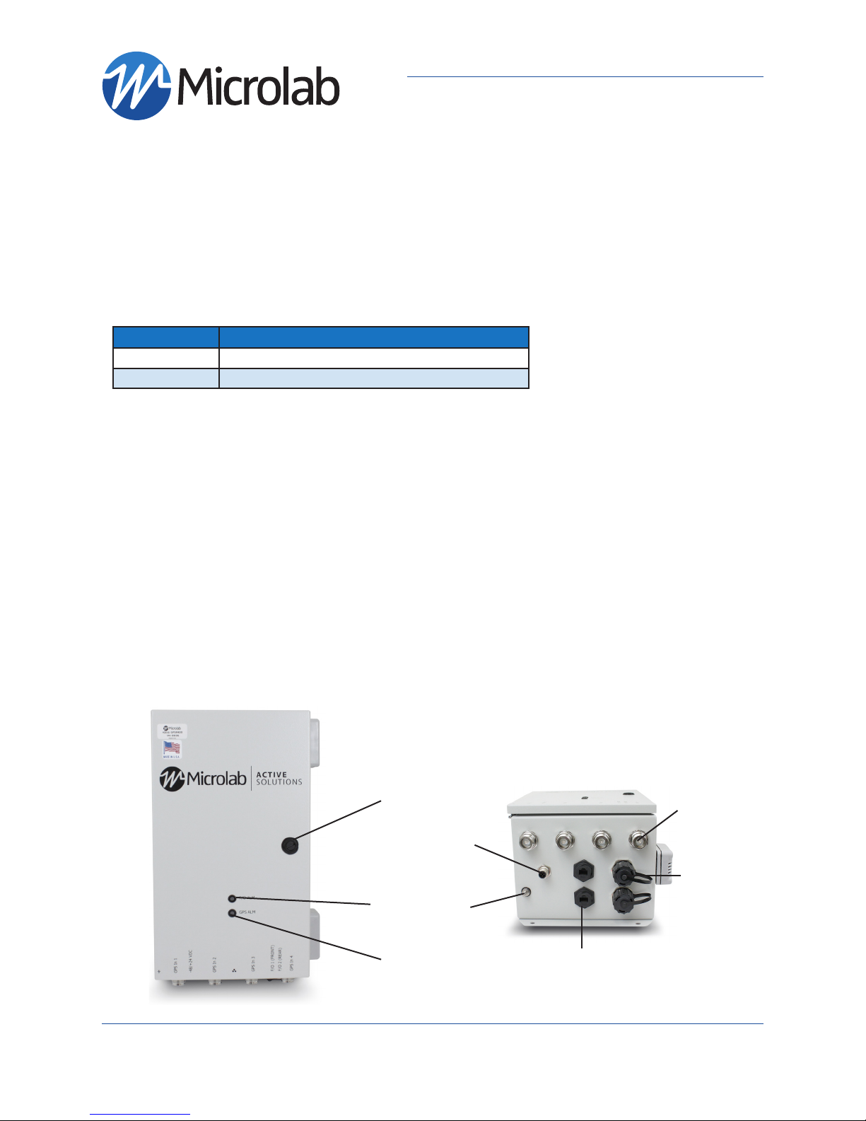
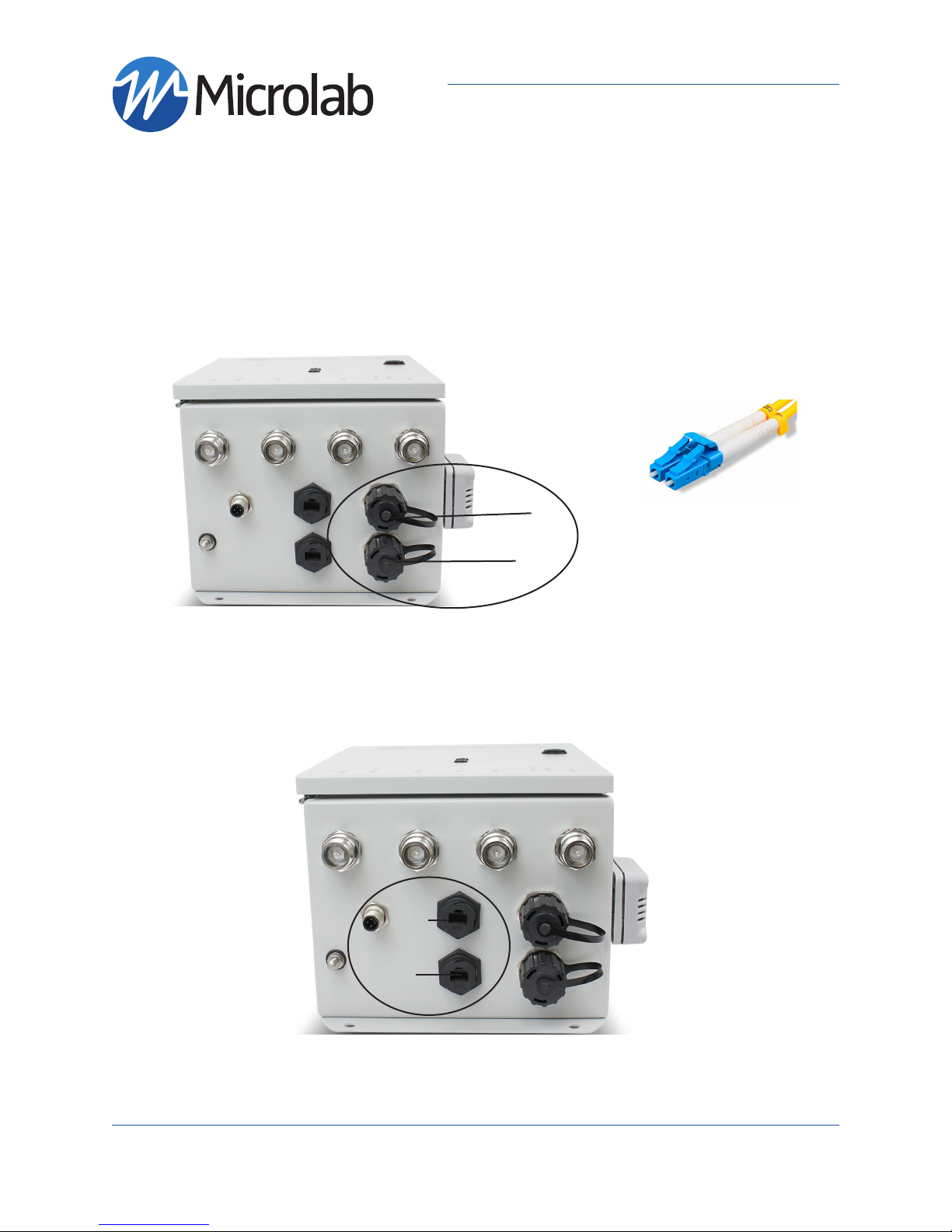
GPSR400 - Front and Bottom Panels
Note: Product appearance varies by model
Hardware Needed
The following items are recommended for Setup and operation:
• M10 Mounting Screws
• -48/+24VDC power supply with included power cable
OR Microlab GPSA003 AC/DC Adapter (not included)
• One ethernet cable (RJ45 connectors)
• One PC or Laptop with an ethernet port or ethernet USB
adapter
• Singlemode duplex fiber < 2km in length
(with Duplex LC/UPC Interfaces)
Please contact Sales for other fiber length requirements.
Service Locks
(M12) MALE
RECEPTACLE
DC POWER
Fiber status
LED
Ground
Nut
Antenna
RF Inputs
4.3-10 Female
OPTICAL ADAPTER,
LC/UPC DUPLEX,
SINGLEMODE
Microlab, A Wireless Telecom Group Company, 25 Eastmans Road, Parsippany, NJ 07054
Tel: (973) 386-9696 • sales@microlabtech.com • www.microlabtech.com • Fax: (973) 386-9191
GPS status
LED
RJ45 CAT6
Ethernet
Ports
Page 3
GPSR400 Quick Start Guide
US Model, 4-Channel Remote Outdoor Unit
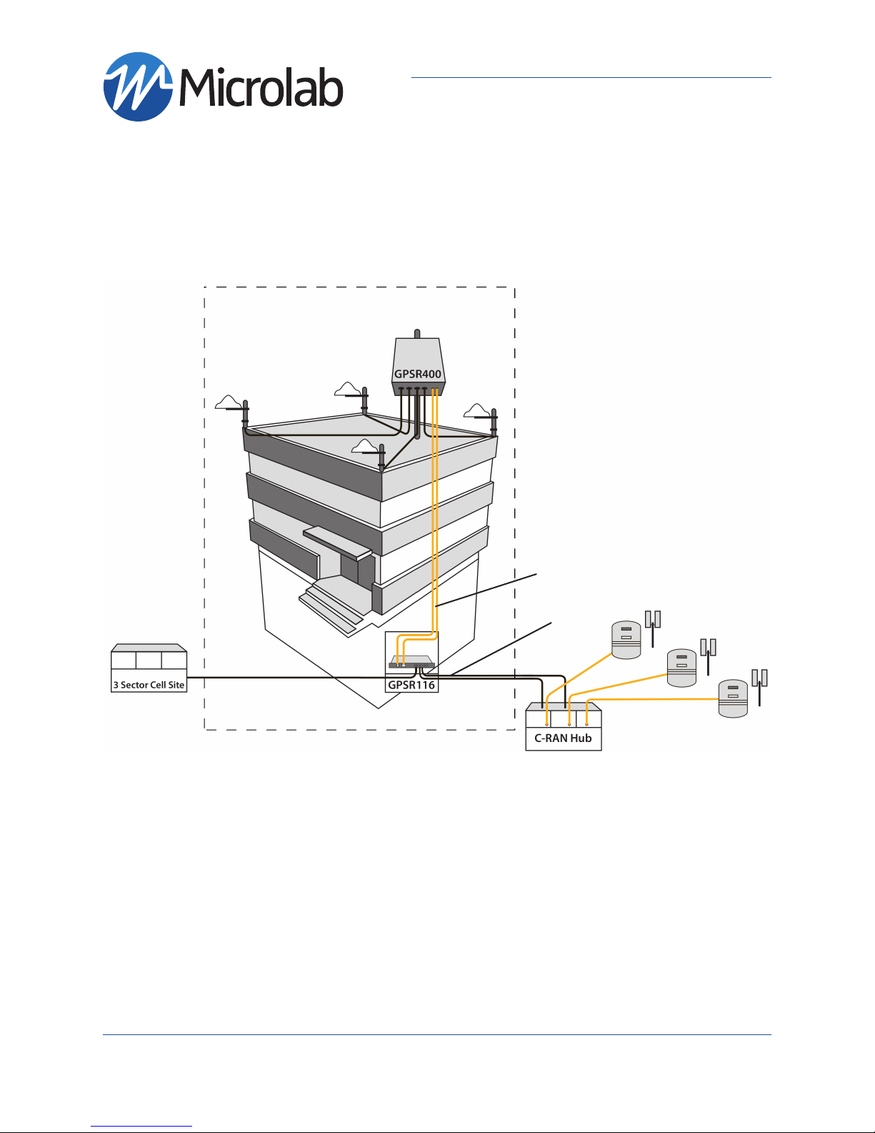
System Connection Diagram
The following diagram illustrates how the GPS repeater system is utilized
GPS Repeater System
page 3
Fiber
Cables
Coax
Cables
Mounting Installation
This GPS signal transmission system is designed to be setup by professional communications systems
installers.
Remote model GPSR400 should be mounted securely using the four enclosure mounting brackets provided.
GPSR400 remote units should be mounted flat against a wall or column with connection panel at bottom.
Provide adequate space of at least 1 foot at the bottom for all system connections.
In a well structured support wall that it is reinforced with a 3/4 inch thick plywood of additional backing,
mount the enclosure using four (4) M10 screws (not included) to bear the unit weight.
Microlab, A Wireless Telecom Group Company, 25 Eastmans Road, Parsippany, NJ 07054
Tel: (973) 386-9696 • sales@microlabtech.com • www.microlabtech.com • Fax: (973) 386-9191
Page 4
GPSR400 Quick Start Guide
US Model, 4-Channel Remote Outdoor Unit
page 4
Connections RF, Optical, and Ethernet
Follow these steps for connecting and disconnecting RF and optical fiber cables to the unit. Make all connections before powering up the remote unit.
Connect fiber optic and RF cables as shown in the System Connection Diagram.
It is recommended that the companion Head End Unit has been properly installed, Fiber-Fed, and Powered ON before Installing the Remote unit. Please refer to Head End Unit User Manual.
If Head-End unit is not installed, skip the Fiber LED status verification in the “LED/System Verification”
section.
Sequence to connect:
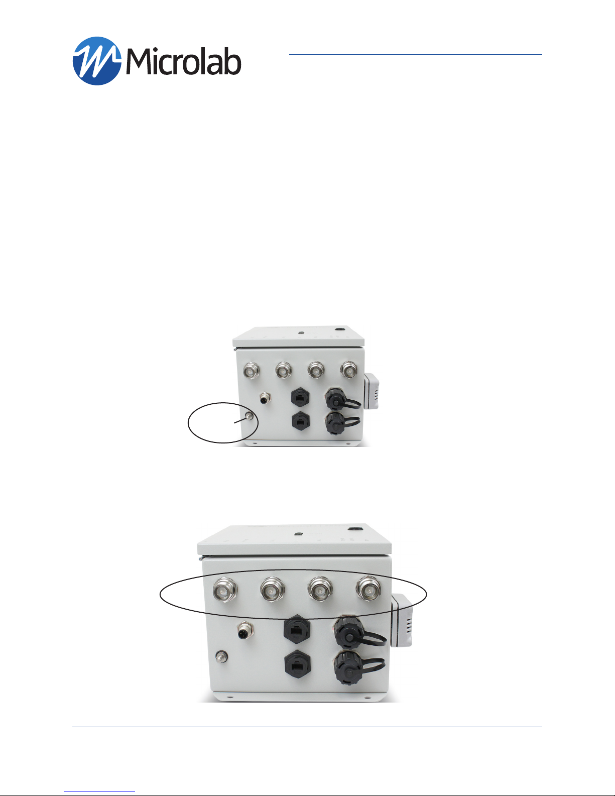
1. Connect System Ground.
- The remote unit comes with a .25-20FLANGENUT grounding lug. A grounding wire of suitable
gauge must be used to ground to a common bus bar in the Telecom room according to local and
building regulations.
Ground Lug
2. Connect GPS Antennas to ports GPS In 1, GPS In 2, GPS In 3, and GPS In 4.
- Two (2) antennas required for operation.
- Apply coupling torque of 5 Nm to 4.3-10 connectors
- Only use operator approved GPS Antennas
GPS IN 1
GPS IN 2
GPS IN 3
GPS IN 4
Microlab, A Wireless Telecom Group Company, 25 Eastmans Road, Parsippany, NJ 07054
Tel: (973) 386-9696 • sales@microlabtech.com • www.microlabtech.com • Fax: (973) 386-9191
Page 5
GPSR400 Quick Start Guide
US Model, 4-Channel Remote Outdoor Unit
page 5
Connections RF, Optical, and Ethernet (Continued)
3. Connect Singlemode duplex fiber with Duplex LC/UPC Interfaces to optical port F/O 1 (Other Interfaces
available)
- Fiber length must be shorter than 2km Please contact Sales for other fiber length requirements
- Clean fiber before connecting
- Optical ports can be connected in any manner
- Only one optical fiber connection needed for operation.
- Recommended second fiber connected to optical port F/O 2 for redundancy.
F/O 1
F/O 2
LC/UPC Duplex
Interface
4. (Optional) Connect Ethernet Cable to the unit’s Ethernet Local port
Local/Debug port used for on-site debugging while maintaining connection to the NOC (Network
operations center)
Note: Both Ethernet ports on the GPSR400 are a transparent bridge. Both Remote Unit and HeadEnd supports Ethernet over CPRI. Either unit can provide a local network connection to the other. See section
“System Configuration and Operation”
Local
DO NOT CONNECT THE REMOTE UNIT AND HEAD-END TO THE SAME SWITCH. CONNECTING BOTH UNITS ON
Microlab, A Wireless Telecom Group Company, 25 Eastmans Road, Parsippany, NJ 07054
Tel: (973) 386-9696 • sales@microlabtech.com • www.microlabtech.com • Fax: (973) 386-9191
Local/
Debug
THE SAME LAN WILL CREATE A BRIDGE LOOP
Page 6

GPSR400 Quick Start Guide
US Model, 4-Channel Remote Outdoor Unit
Connecting Power
Power up Sequence:
Required:
• -48/+24VDC power source with the included power cable. Follow wiring diagram shown
• OR use the Microlab GPSA003 AC/DC power supply (not included)
Power Cable (Part#: 1-2273029-1)
Connect DC Positive and Negative
terminals as follow:
1. Brown /Positive (+)
2 White /Positive (+)
4. Black /Negative (-)
3. Blue /Negative (-)
page 6
1. Carefully align and mate the power cable M12 Female connector to the remote unit’s Power M12 Male
Receptacle
-48/+24 VDC
2. Turn on DC power source or plug-in the Microlab GPSA003 to the 100-240VAC outlet.
- If the remote unit is deployed with the power supply, both LEDs will illuminate.
- Off Status LEDs indicate that power supply is not functioning or not connected.
Note: Bootup time is approximatelly 60 seconds. During this time both front panel LEDs will be Yellow.
After system bootup, LEDs will illuminate RED while waiting for GPS signal lock and Fiber Link connection.
Microlab, A Wireless Telecom Group Company, 25 Eastmans Road, Parsippany, NJ 07054
Tel: (973) 386-9696 • sales@microlabtech.com • www.microlabtech.com • Fax: (973) 386-9191
Page 7

GPSR400 Quick Start Guide
US Model, 4-Channel Remote Outdoor Unit
page 7
LED/System Verification
3. Verify GPS and Fiber Link status LEDs turn GREEN to ensure proper GPS repeater operation
- Fiber Status:
- Allow up to 5 seconds for fiber/CIPRI connection between Head End and Remote unit to be
established and illumilate LED GREEN.
- GPS Status:
- Allow up to 5 minutes for GPS signal acquisition.
- If GPS signal is locked, LED will illuminate GREEN.
F/O ALM
LED
GPS ALM
LED
BootupProper Operation
LED Indicators
• Fiber Status:
○ Illuminates Yellow during bootup
○ Illuminates RED while waiting for link with the head-end
○ Illuminates GREEN when link is established with Head-End Unit connected to
fiber ports F/O 1 OR F/O 2
• GPS Status:
○ Illuminates Yellow during bootup
○ Illuminates RED while waiting for GPS signal acquisition
○ Illuminates GREEN when GPS signal has been locked on any antenna
Note: If there is an error during bootup. Both LED’s will remain Yellow. Disconnect and reconnect DC power to
the unit. If problem persists, please contact Customer Service for troubleshooting assistance.
No GPS Lock/
Fiber Link Down
No GPS Lock/
Fiber Link Up
GPS Lock/
Fiber Link Down
Microlab, A Wireless Telecom Group Company, 25 Eastmans Road, Parsippany, NJ 07054
Tel: (973) 386-9696 • sales@microlabtech.com • www.microlabtech.com • Fax: (973) 386-9191
Page 8

GPSR400 Quick Start Guide
US Model, 4-Channel Remote Outdoor Unit
System Configuration and Operation
The web interface is accessed as described in the following sections. First, the unit must be connected to a
router or directly to a computer or laptop via an ethernet cable (Use designated Local/Debug port on the
GPSR400).
System Access
Default TCP/IP: 192.168.1.200 (Remote Units)
Default TCP/IP: 192.168.1.201 (Head-End Units)
If the unit is connected directly to a PC/laptop (Windows 10 Recommended)
1. Open the start menu and click on Control Panel.
page 8
2. Open “Network and Sharing Center”
Microlab, A Wireless Telecom Group Company, 25 Eastmans Road, Parsippany, NJ 07054
Tel: (973) 386-9696 • sales@microlabtech.com • www.microlabtech.com • Fax: (973) 386-9191
Page 9

System Configuration and Operation (Continued)
3. Click “Change adapter settings”
4. Right click the Network Adapter and open its Properties
GPSR400 Quick Start Guide
US Model, 4-Channel Remote Outdoor Unit
page 9
5. Double click “Internet Protocol Version 4 (TCP/IPv4)”
Microlab, A Wireless Telecom Group Company, 25 Eastmans Road, Parsippany, NJ 07054
Tel: (973) 386-9696 • sales@microlabtech.com • www.microlabtech.com • Fax: (973) 386-9191
Page 10

GPSR400 Quick Start Guide
US Model, 4-Channel Remote Outdoor Unit
System Configuration and Operation (Continued)
6. Check “Use the following IP address” and enter the following settings. Press “OK” to save the settings
IP address: 192.168.1.20 (address must be within the range of the GPSR400 subnet)
Range: 192.168.1.1 - 192.168.1.254
Subnet mask: 255.255.255.0
Default gateway: 0.0.0.0
page 10
Web Console
After following the steps in the previous section. Open an internet browser and type the address
http://192.168.1.200. The system log-in page should appear. Type in the default admin username and
password.
Username and Password
Username: admin
Password: admin
Note the password is case sensitive
Microlab, A Wireless Telecom Group Company, 25 Eastmans Road, Parsippany, NJ 07054
Tel: (973) 386-9696 • sales@microlabtech.com • www.microlabtech.com • Fax: (973) 386-9191
Page 11

GPSR400 Quick Start Guide
US Model, 4-Channel Remote Outdoor Unit
Web Console (System Info)
Viewing System Info:
1. Click “System Info” in the menu tree on the left.
2. View the status of each fiber connection to the head-unit under the “Ethernet” section
Working Interfaces CPRI0 and CPRI1 will display Link Up
Otherwise, they will display Link Down
page 11
Microlab, A Wireless Telecom Group Company, 25 Eastmans Road, Parsippany, NJ 07054
Tel: (973) 386-9696 • sales@microlabtech.com • www.microlabtech.com • Fax: (973) 386-9191
Page 12

GPSR400 Quick Start Guide
US Model, 4-Channel Remote Outdoor Unit
Web Console (“GPS A” and “GPS B”)
The GPSR400 unit has two GPS receivers on board for redundancy. These are referred to as “GPS
A” and “GPS B”. Each receiver has the ability to automatically switch over from a primary GPS antenna to a secondary GPS antenna if there is an antenna failure. The GPSR400 actively monitors
the health of all four GPS antennas connected and will seamlessly switch to the best antenna.
Each receiver monitors the following antennas:
- GPS A: “GPS In 1 (Antenna A)” & “GPS In 2 (Antenna B)”
- GPS B: “GPS In 3 (Antenna C)” & “GPS In 4 (Antenna D)”
View Satellite Data:
1. Click “GPS A” or “GPS B” in the menu tree on the left.
2. Satellite information will be displayed under “Satellite Data” if the respective GPS receiver has
successfully locked to a GPS signal on one of it’s corresponding antennas.
Otherwise, no data will be displayed for that GPS receiver.
• Satellite Indicators:
○ Good/Used Satellites WILL be shown in GREEN
○ Satellites NOT used will be shown in Yellow
page 12
Microlab, A Wireless Telecom Group Company, 25 Eastmans Road, Parsippany, NJ 07054
Tel: (973) 386-9696 • sales@microlabtech.com • www.microlabtech.com • Fax: (973) 386-9191
Page 13

GPSR400 Quick Start Guide
US Model, 4-Channel Remote Outdoor Unit
Web Console (App & Alarms)
View Fiber loss
1. Click “Apps & Alarms” in the menu tree on the left.
2. Scroll down to “System Alarms”
3. Verify fiber loss for each CPRI interfaces (SFP Rx Power / SFP Tx Power)
If SFP Rx Power is less than -10 dBm, verify all fiber connections
View Antenna Alarms
Any system Alarms triggered will display RED
1. Under “Apps & Alarms”
2. Scroll down to “System Alarms”
3. Verify that the connected antenna(s) are working properly
Alarms will be GREEN if antennas are working properly
Alarms will be RED if antennas are failing, disconnected or shorted
page 13
Microlab, A Wireless Telecom Group Company, 25 Eastmans Road, Parsippany, NJ 07054
Tel: (973) 386-9696 • sales@microlabtech.com • www.microlabtech.com • Fax: (973) 386-9191
Page 14

GPSR400 Quick Start Guide
US Model, 4-Channel Remote Outdoor Unit
Web Console (App & Alarms)
The table below shows the list of alarm causes and resolutions. All alarms listed are available on the web
interface of GPSR400 and GPSR116. All alarms are also reportable via SNMP.
Alarms: Cause Resoluon
loss of CPRI frame including frame
Local LOF
synchronizaon
Local LOS loss of CPRI signal
remote loss of CPRI frame including
Remote LOF
frame synchronizaon
Remote LOS remote loss of CPRI signal
SFP LOS loss of SFP signal
SFP Present SFP module not present call tech support to replace the SFP module
Antenna port A not connected
Antenna A
(open or short)
Antenna port B not connected
Antenna B
(open or short)
GPS receiver A not locked to GPS
GPS A Lock
satellite signals
GPS recevier A is not selected as
GPS A Selected
signal source
Antenna port C not connected
Antenna C
(open or short)
Antenna port D not connected
Antenna D
(open or short)
GPS receiver B not locked to GPS
GPS B Lock
satellite signals
GPS recevier B is not selected as
GPS B Selected
signal source
GPS Lock local GPS receiver is not locked check CPRI, SFP and antennas as above
check opcal ber cable, connecon and opcal
power on both ends
GPS A:
check antenna A, cable, connecon and +5VDC at
“GPS In 1” port of GPSR400
check antenna B, cable, connecon and +5VDC at
“GPS In 2” port of GPSR400
check antenna A, Antenna B, cable, conecon and
+5VDC as above
OK if the other GPS is selected, otherwise check
GPS A Lock as above
GPS B:
check antenna C, cable, connecon and +5VDC at
“GPS In 3” port of GPSR400
check antenna D, cable, connecon and +5VDC at
“GPS In 4” port of GPSR400
check antenna C, antenna D, cable, conecon and
+5VDC as above
OK if the other GPS is selected, otherwise check
GPS B Lock as above
Local GPS:
page 14
Notes
CPRI : Common Public Radio Interface
SFP: (Small Form-factor Pluggable) A transceiver for optical fiber cable
GPS A is connected to either Antenna A (“GPS In 1”) or Antenna B (“GPS In 2”)
GPS B is connected to either Antenna C (“GPS In 3”) or Antenna D (“GPS In 4”)
Either RF path of GPS A or RF path of GPS B is selected as input to Local GPS and BS
Microlab, A Wireless Telecom Group Company, 25 Eastmans Road, Parsippany, NJ 07054
Tel: (973) 386-9696 • sales@microlabtech.com • www.microlabtech.com • Fax: (973) 386-9191
Page 15

GPSR400 Quick Start Guide
US Model, 4-Channel Remote Outdoor Unit
Web Console (Network)
Change Default IPv4 Network Settings
1. Click “Network” under “Setup” in the menu tree on the left.
2. Select the IP version to be configured (IPv4)
2.1 Set the desired IP address of the GPSR400. It should be within the range of the gateway.
2.1.1 Default IP Address: 192.168.1.200
2.2 Set the subnet mask of the router
2.2.1 Default Subnet Mask: 255.255.255.0
2.3 Set the gateway of the router (the router’s IP address)
2.3.1 Default Gateway: 192.168.1.254
2.4 Set Primary and Seconday DNS addresses
2.4.1 Default Primary DNS: 192.168.1.254
2.4.2 Default Secondary DNS: 8.8.8.8
3. Click the Apply button (Current page will not refresh)
4. Reopen internet browser and type the newly configured IP address
4.1 Popup will appear confirming “Successfully configure the Network”. Press “OK” to continue
4.2 The system log-in page should appear.
4.3 Type in the admin username and password.
page 15
Microlab, A Wireless Telecom Group Company, 25 Eastmans Road, Parsippany, NJ 07054
Tel: (973) 386-9696 • sales@microlabtech.com • www.microlabtech.com • Fax: (973) 386-9191
Page 16

Disconnecting/Uninstalling
Sequence to Disconnect:
1. Remove/Disconnect DC power to the device
2. Disconnect the RF Antenna connections of the unit.
3. Disconnect optical input of the unit.
4. Disconnect Ethernet connection of the unit (if ethernet-fed).
5. Disconnet Ground
6. Unmount Unit
GPSR400 Quick Start Guide
US Model, 4-Channel Remote Outdoor Unit
page 16
Disclaimer
GPS and GNSS re-transmission to an antenna requires regulatory approval. These approvals are granted on an
individual basis by regulating bodies. Microlab cannot grant these approvals, and cannot be held responsible
for violating these regulations using the system.
The FCC requires commercial users within the US to acquire and maintain a Part 5 experimental license to
re-broadcast GPS signals. Licenses are not required if they are inside an RF shielded environment. European
regulations vary by country. Consult local authorities for additional details.
Contact Microlab - Active Solutions
To contact Microlab, visit our website at www.microlabtech.com or send email to sales@microlabtech.com.
For operating assistance in the USA, call (973) 386-9696.
Safety Information
To avoid possible electric shock or personal injury, the following general safety precautions must be observed
during all phases of operation, service, or repair of the Microlab Unit . Failure to comply with these precautions
or with specific warnings in this guide violates the safety standards of design, manufacture, and intended
use of the Microlab Unit. Microlab assumes no liability for the customer’s failure to comply with these requirements.
Microlab, A Wireless Telecom Group Company, 25 Eastmans Road, Parsippany, NJ 07054
Tel: (973) 386-9696 • sales@microlabtech.com • www.microlabtech.com • Fax: (973) 386-9191
 Loading...