

Page 1

XZR500ST
Oxygen Analyzer
User’s Manual
97137 Issue 8
April 2017
Page 2

Please fi ll out the form(s) below for each instrument that has been purchased.
Use this information when contacting Michell Instruments for service purposes.
Analyzer
Code
Serial Number
Invoice Date
Location of Instrument
Tag No
Analyzer
Code
Serial Number
Invoice Date
Location of Instrument
Tag No
Analyzer
Code
Serial Number
Invoice Date
Location of Instrument
Tag No
Page 3
© 2017 Michell Instruments
This document is the property of Michell Instruments Ltd. and may not be copied or
otherwise reproduced, communicated in any way to third parties, nor stored in any Data
Processing System without the express written authorization of Michell Instruments Ltd.
XZR500
For Michell Instruments' contact information please go to
www.michell.com
Page 4

XZR500 User’s Manual
iv 97137 Issue 8, April 2017
1 INTRODUCTION ................................................................................................1
1.1 System Description ............................................................................................. 1
1.1.1 Measurement Principle .................................................................................. 1
1.1.2 Zirconia ........................................................................................................ 1
1.1.3 The MSRS .................................................................................................... 2
1.1.4 XZR500 MSRS Assembly ............................................................................... 2
1.2 General Remarks ................................................................................................ 3
1.2.1 Sensor Head and Probe ................................................................................. 3
1.2.2 Control Unit .................................................................................................. 4
1.3 Specifi cations .................................................................................................... 6
1.3.1 General ........................................................................................................ 6
1.3.2 Optional Equipment ....................................................................................... 8
1.3.3 Options ........................................................................................................ 8
2 INSTALLATION ..................................................................................................9
2.1 General Mounting Precautions ............................................................................ 9
2.2 Probe Mechanical Installation .......................................................................... 10
2.3 Control Unit Mechanical Installation ................................................................... 13
2.4 Wiring ............................................................................................................. 13
2.4.1 Cable Specifi cations ..................................................................................... 13
2.4.2 Connection of the Cable (supplied) to the Control Unit ................................... 13
2.4.2.1 Connection to the Mains ........................................................................ 14
2.4.2.2 Connection of the 0/4-20 Output ............................................................ 14
2.4.2.3 Connection of the Alarms ....................................................................... 14
2.4.3 Connection of the Cable to the Sensor Head ................................................. 14
3 OPERATION ....................................................................................................16
3.1 Outputs ........................................................................................................... 16
3.1.1 Analog Output ............................................................................................ 16
3.1.2 Alarms ....................................................................................................... 16
3.2 Start-Up ........................................................................................................... 17
3.3 Display, Confi guration and Adjustment ............................................................... 18
3.3.1 Visualization Menu [*] ................................................................................. 18
3.3.2 Set-up [ - ] ................................................................................................. 21
3.3.2.1 Access code 0.12 - quick settings ........................................................... 22
3.3.2.2 Access code 0.20 - advanced settings ..................................................... 24
3.3.3 Calibration [+] ............................................................................................ 29
3.3.3.1 Recommended Calibration Gas ............................................................... 29
3.3.3.2 Regulating the Calibration Flow Rate ...................................................... 29
3.3.3.3 Calibration Procedure ............................................................................ 30
Contents
Safety ...............................................................................................................................vii
Electrical Safety .......................................................................................................... vii
Pressure Safety ........................................................................................................... vii
Temperature ............................................................................................................... vii
Toxic Materials ............................................................................................................ vii
Repair and Maintenance .............................................................................................. vii
Calibration .................................................................................................................. vii
Safety Conformity ....................................................................................................... vii
Abbreviations .................................................................................................................... viii
Warnings .......................................................................................................................... viii
Page 5

XZR500 User’s Manual
Michell Instruments v
Figures
Figure 1 Zirconia Principle ........................................................................................1
Figure 2 The MSRS and its K Thermocouple ..............................................................2
Figure 3 XR500 MSRS ..............................................................................................2
Figure 4 XZR500 Sensor Head & Probe .....................................................................3
Figure 5 Digital Display Panel ...................................................................................4
Figure 6 Main Display ..............................................................................................4
Figure 7 Control Unit .............................................................................................5
Figure 8 Probe Installation .....................................................................................10
Figure 9 Probe Head Orientation .............................................................................10
Figure 10 Flange Gasket Orientation .........................................................................11
Figure 11 Tubular Counter Flange Position ................................................................11
Figure 12 Inner Tube Orientation ..............................................................................12
Figure 13 Hex Screw Locations .................................................................................14
Figure 14 Probe Wiring Diagram ...............................................................................15
Figure 15 Calibration Flow-Chart...............................................................................33
Figure 16 XZR500 MSRS Mounting Diagram ..............................................................35
Figure 17 XZR500 Top View .....................................................................................36
Figure 18 XZR500 Side View ....................................................................................36
Figure 19 XZR500 Sensor Head & Probe General Dimensions .....................................50
Figure 20 Position of the Probe ................................................................................52
Figure 21 Installation of the Ejector/Heating System .................................................55
Figure 22 Enclosure for Controlling the Ejector Heating - General Wiring Diagram ........56
Figure 23 XZR500 Flange and Back Flange (Optional) ................................................59
Figure 24 Insulators (Flange and Rear Sealing Screw) ................................................59
Figure 25 Mounting Plate Dimensions ....................................................................... 60
Figure 26 Wiring of the Second 4-20 mA Output ........................................................62
4 MAINTENANCE ................................................................................................ 34
4.1 Preventative Maintenance - Cleaning .................................................................. 34
4.2 Replacement Of The XZR500 MSRS .................................................................. 35
4.3 Replacement of the Furnace .............................................................................. 37
4.4 Replacement of the XZR500 Microcontroller Card ................................................ 38
4.5 Replacement of Fuses ....................................................................................... 38
4.6 Error Messages ............................................................................................... 39
5 SPARE PARTS ..................................................................................................41
Page 6

XZR500 User’s Manual
vi 97137 Issue 8, April 2017
Appendices
Appendix A Technical Specifi cations ..............................................................................43
Appendix B Confi guration for the RS232 Port (Optional) .................................................45
Appendix C Calculation of CO
2
....................................................................................48
Appendix D XZR500 Sensor Head and Probe General Dimensions ...................................50
Appendix E Back Flushing System (optional) .................................................................52
Appendix F Heated Flue Gas Ejection System (Optional) ................................................55
Appendix G Mounting Options ......................................................................................59
G.1 Tubular Counter Flange and Insulators ..........................................59
G.2 Mounting Plate Dimensions ..........................................................60
Appendix H Second 4-20 mA Output .............................................................................62
Appendix I Automatic Calibration (Optional) ................................................................64
Appendix J Quality, Recycling & Warranty Information ...................................................66
Appendix K Return Document & Decontamination Declaration ........................................68
Tables
Table 1 Control Keys...............................................................................................5
Table 2 Maximum Temperature of Gases .................................................................. 7
Table 3 Cable Specifi cations .................................................................................. 13
Table 4 Connection of the Control Unit................................................................... 13
Table 5 Access codes 0.12 & 0.20 ......................................................................... 21
Table 6 Alarm Set-Point Examples ......................................................................... 23
Table 7 Fuse Replacement .................................................................................... 38
Page 7

XZR500 User’s Manual
Michell Instruments vii
Safety
The manufacturer has designed this equipment to be safe when operated using the procedures
detailed in this manual. The user must not use this equipment for any other purpose than that
stated. Do not apply values greater than the maximum value stated.
This manual contains operating and safety instructions, which must be followed to ensure the safe
operation and to maintain the equipment in a safe condition. The safety instructions are either
warnings or cautions issued to protect the user and the equipment from injury or damage. Use
qualifi ed personnel and good engineering practice for all procedures in this manual.
Electrical Safety
The instrument is designed to be completely safe when used with options and accessories supplied
by the manufacturer for use with the instrument. The input power supply voltage is 230 V AC or 115
V AC, 50/60 Hz. Refer to labels on instrument or calibration certifi cate.
Pressure Safety
DO NOT permit pressures greater than the safe working pressure to be applied to the instrument.
The specifi ed safe working pressure, for all versions of this instrument, is 10 bar.
Temperature
Some parts of the analyzer can be at a very high temperature. DO NOT open the enclosure of the
probe during operation. Switch off the analyzer fi rst and wait for at least 30 minutes.
Toxic Materials
The use of hazardous materials in the construction of this instrument has been minimized. During
normal operation it is not possible for the user to come into contact with any hazardous substance
which might be employed in the construction of the instrument. Care should, however, be exercised
during maintenance and the disposal of certain parts. Long exposure or breathing of the calibration
gases may be dangerous.
Repair and Maintenance
The instrument must be maintained either by the manufacturer or an accredited service agent. Refer
to www.michell.com for details of Michell Instruments’ worldwide offi ces contact information.
Calibration
The recommended calibration interval for the analyzer is 6 to 12 months depending on the application
in which the instrument is used.
Safety Conformity
This product carries the CE mark and meets the requirements of relevant European safety directives.
Page 8

XZR500 User’s Manual
viii 97137 Issue 8, April 2017
Abbreviations
The following abbreviations are used in this manual:
AC alternating current
A Ampere
°C degrees Celsius
°F degrees Fahrenheit
Hz hertz
kg kilogram(s)
l/hour liters per hour
mA milli Ampere
mbars millibars
mm millimeter(s)
ppm parts per million
T Temperature
V Volt
W Watts
Warnings
The following general warnings listed below are applicable to this instrument. They are
repeated in the text in the appropriate locations.
Where this hazard warning symbol appears in the following
sections it is used to indicate areas where potentially
hazardous operations need to be carried out.
Where this symbol appears in the following sections it is used
to indicate areas of potential risk of electric shock.
Page 9

XZR500 User’s Manual
Michell Instruments 1
INTRODUCTION
1 INTRODUCTION
XZR500 Series Oxygen Analyzers are designed to measure the oxygen content in
fl ue gases between 0.01% and 25% O
2
. They allow for the improvement of a boiler’s
performance, increasing equipment service life and surveying emissions, thereby
contributing to protecting the environment.
XZR500 Oxygen Analyzers can be used for several applications such as monitoring
combustion in power plants, incineration of industrial or domestic waste, incineration of
VOC, control of processes, etc.
Please read this manual carefully before starting up the analyzer. It is recommended
that you go through this manual again after the fi rst use to enable optimal use of the
XZR500.
1.1 System Description
1.1.1 Measurement Principle
Michell Instruments’ aim is to provide the best measurement solutions for any
given industrial process or laboratory application. In the case of oxygen control and
measurement we have developed a highly advanced and miniaturized oxygen sensor,
the MSRS. This innovative sensor is at the heart of the XZR500 analyzer. A key strength
of the MSRS is that it has a built-in metal reference, this means it can operate for very
long periods without any requirement for re-calibration against a reference gas. As a
result the XZR500 has very low lifetime costs compared to other oxygen analyzers.
In addition to providing reliable and hassle free operation, the MSRS also delivers
excellent accuracy, class-leading linearity and, due to its small size, has a superior
response speed.
The operating principle of the MSRS is explained in detail as follows:
1.1.2 Zirconia
Zirconia is a solid electrolyte. At high temperatures
it conducts oxygen ions. An electrochemical voltage
develops between the two platinum-plated surfaces
of the zirconia in contact with two different gaseous
oxygen partial pressure (Pp) atmospheres. This voltage
follows the Nernst equation, expressed as:
E =
RT
ln
Ppmeas.
4F Ppref.
Figure 1
Zirconia Principle
where R and F are constants
E = Nernst voltage (V)
T = temperature (°K)
Pp = oxygen partial pressures
Page 10
XZR500 User’s Manual
2 97137 Issue 8, April 2017
INTRODUCTION
By setting the oxygen reference pressure and measuring voltage E and temperature T,
you can deduce the oxygen partial pressure you want to measure.
The volumetric concentration (expressed here in O
2
%vol.) is determined by the ratio
between the oxygen partial pressure (Ppmeas) and the atmospheric pressure (Ptot).
O2 %vol. =
Ppmeas.
Ptot.
There is an optional ambient pressure sensor available for higher accuracy measurements.
1.1.3 The MSRS
Figure 2
The MSRS and its K Thermocouple
Unlike conventional “air reference” zirconia sensors the MSRS uses the equilibrium
status of an internal metal oxide to provide a reference. Therefore, this built-in metallic
reference sensor does not require any reference gas.
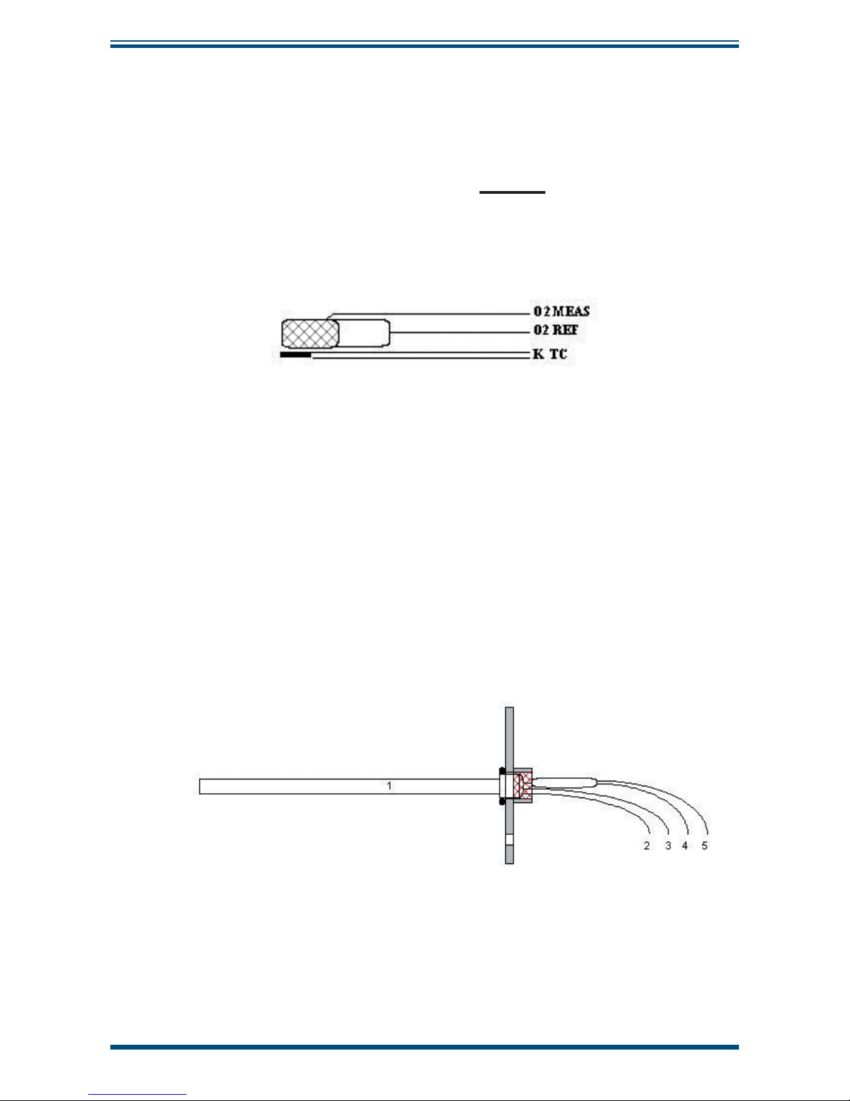
The MSRS is a very small cylinder, 3mm in diameter and 10mm long. A K thermocouple,
placed closed to the MSRS, measures its temperature with great precision. This design
leads to extremely high accuracy and very good resistance to thermal shocks. It also
increases the lifetime of the sensor.
1.1.4 XZR500 MSRS Assembly
The MSRS and its K thermocouple are placed inside an aluminum tube. The MSRS head
is attached to an assembly plate to allow for easier fi eld servicing, see
Figure 3
below.
1. aluminum tube
2. O2 reference wire with blue mark
3. O2 reference wire with red mark
4. + thermocouple wire with green mark
5. - thermocouple wire with white mark
Figure 3
XR500 MSRS
Page 11
XZR500 User’s Manual
Michell Instruments 3
INTRODUCTION
1.2 General Remarks
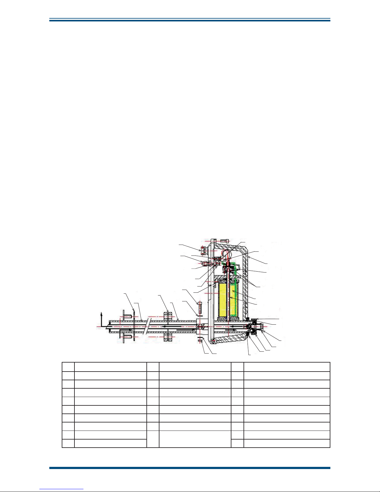
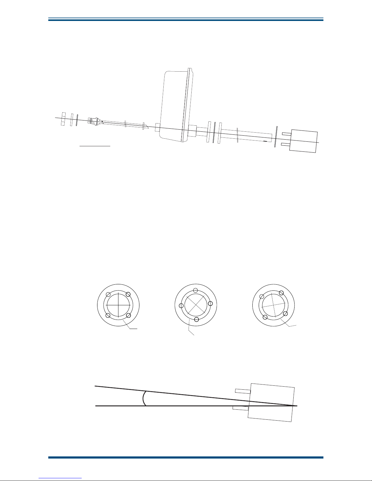
The analyzer is made up of a measurement probe and a Control Unit.
1.2.1 Sensor Head and Probe
The semi in-situ arrangement consists of the following elements:
• Sensor head, containing MSRS, sensor furnace, cable connection &
calibration port.
• Probe, comprising of an inner and outer tube to allow fl ow of sample from
fl ue to sensor.
The sample gas is returned to the fl ue practically unchanged in composition and
condition. This is due to the very small amount of sample required to diffuse into the
sensor furnace.
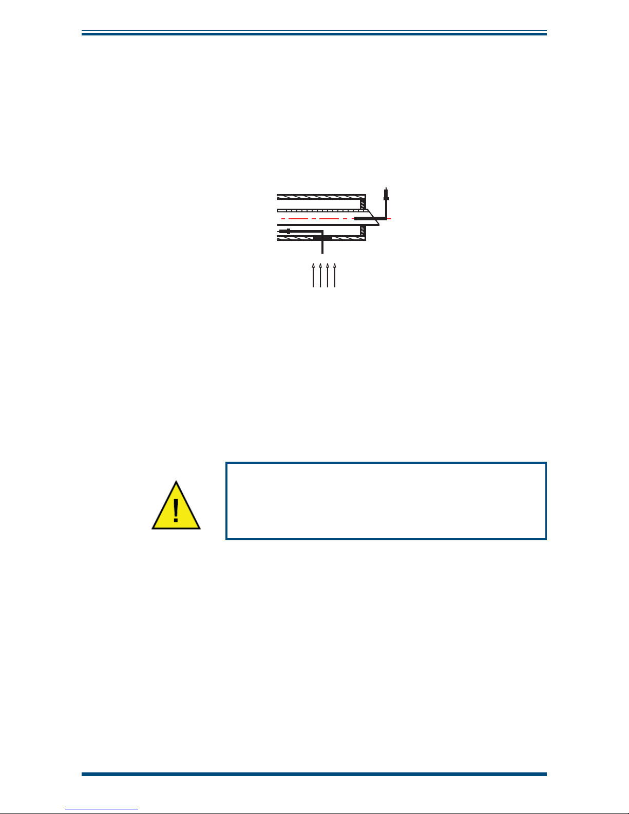
The gas fl ow is shown by the arrows in
Figure 4
below. In this example, the stack is
vertical and the fl ue gas fl ow direction is upwards.
Using the Pitot tube effect, gases enter through the hole near the tip of the outer tube
and circulate in the space between the outer tube (25, 2) and the inner tube (23).
During this process the gases contact the sensor through diffusion. They then fl ow into
the inner tube and to the fl ue via the bevelled edge.
The tubes are fi tted so that the bevelled edge of the inner tube and the holes of the
outer tube face in opposite directions.
8
25
6
2
1
3
4
5
7
9
10
11
12
13
14
15
16
17
18
19
20
21
24
22
23
26
27
28
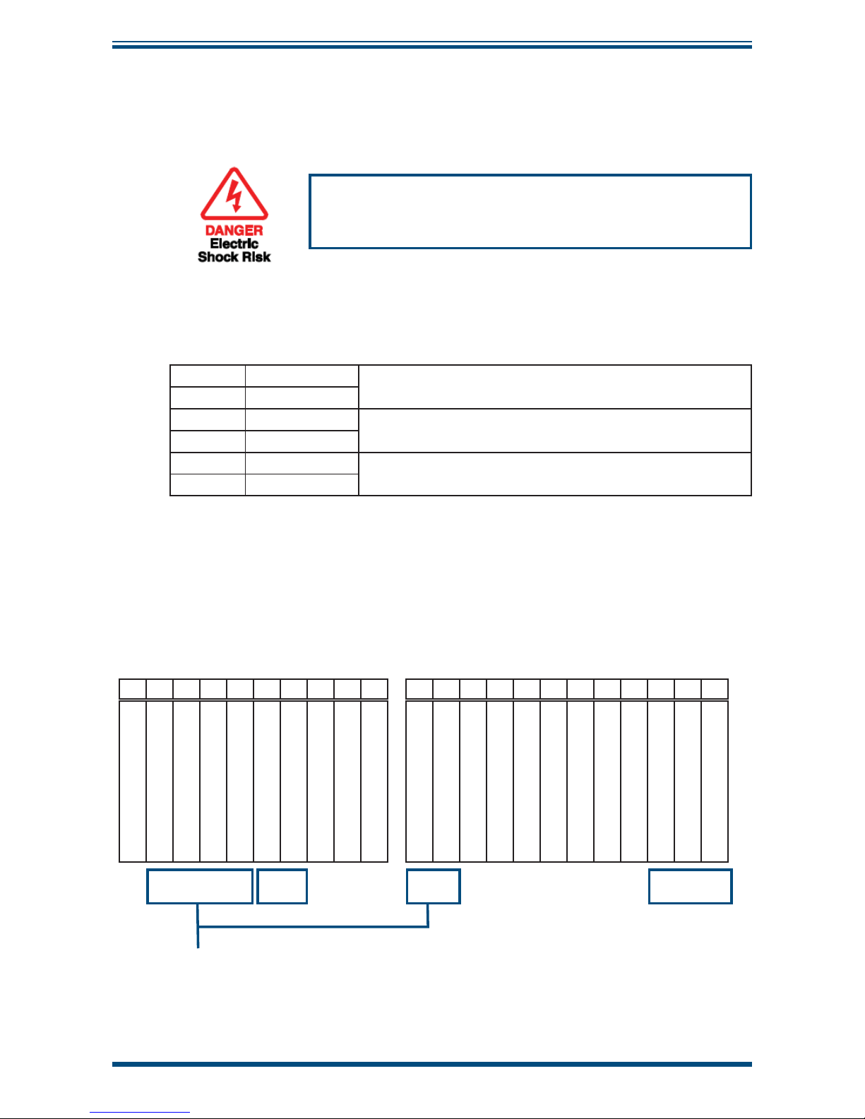
29
1 Sensor housing 11 XZR500 connector block 20 M6 Nut for fi xing XZR500 probe plate
2 Outer tube 12 SS bulkhead union for cal.gas 21 M6 washer
3 Sealing head 13 2 sealing ferrules 22 M6 lock washer
4 XZR500 furnace 14 Nut for fi xing bulkhead union 23 Inner tube
5 XZR500 MSRS 15 Stainless steel plug 24 VITON 8 x 2.5 O-ring
6 Gasket for fl ange (x2) 16 M8 lock washer 25 Outer tube
7 Gasket for wheel 17 Cable gland 26 Locking ring
8 Inter-tubes gasket 18 M8 spacer 27 Gasket for plug
9 Gasket for sealing screw 19 CHC 6x25 screw for fi xing
XZR500 sensor attachmt plate
28 Big rear nut
10 TRF 3x16 screw for connector 29 Inter-tube gasket
Figure 4
XZR500 Sensor Head & Probe
Page 12
XZR500 User’s Manual
4 97137 Issue 8, April 2017
INTRODUCTION
The XZR500 MSRS (5) assembly is placed perpendicular to the tubing system. The
XZR500 furnace (4) and the XZR500 MSRS (5) are placed inside a cast aluminum
enclosure which is made of two parts sealed with a 5mm diameter viton O-ring. It is
dust proof and waterproof and can be mounted outdoors. The cable gland (17) is made
of brass.
The whole set is mounted on the stack with a steel fl ange which is welded on the
XZR500 outer tube. Michell Instruments can provide an optional mounting kit containing
a counter fl ange with threaded rods (if needed please refer to Appendix G).
All the gaskets (6, 7, 8 and 9) placed on the tubes are made of carbon fi ber.
A high temperature “gasket box” type device guarantees that the sealing head is airtight.
For dimensions of the measuring probe see Appendix D.
1.2.2 Control Unit
The Control Unit provides the Human Machine Interface (HMI) for the XZR500 analyzer.
It is housed in a metal case with a screen and three touch buttons to allow access to
menus. Inside there is a motherboard, a micro-controller and a display PCB. The output
signals and alarms are all accessed through the Control Unit.
Oxygen concentration is displayed on the screen as default and has one decimal
point as standard (a second decimal place can be requested as an option). Other
parameters available through the HMI are Furnace Temperature, Thermocouple Junction
Temperature, MSRS Voltage and Ambient Pressure (in mbars), if the optional pressure
sensor is ordered.
Confi guration of alarms and output signals as well as calibration functions are all carried
out through the HMI of the Control Unit.
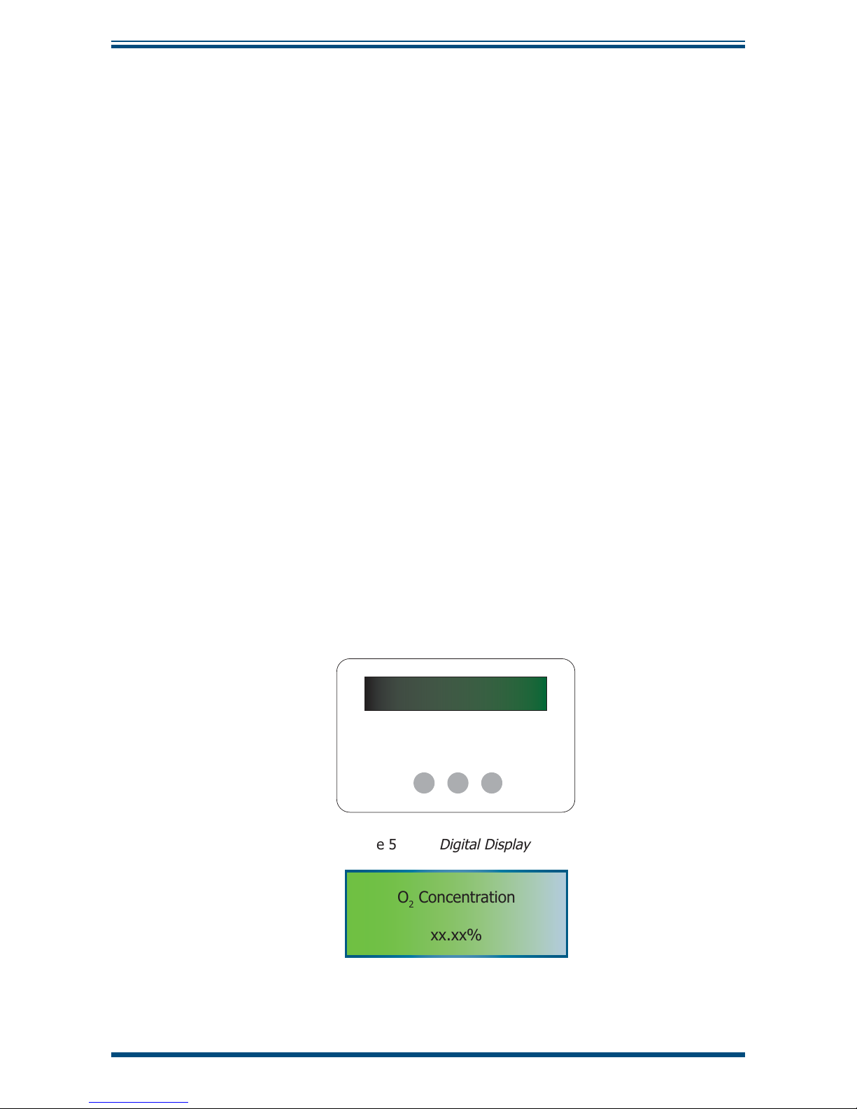
The digital display panel of the analyzer is shown in
Figure 5
.
-
*
+
Figure 5
Digital Display Panel
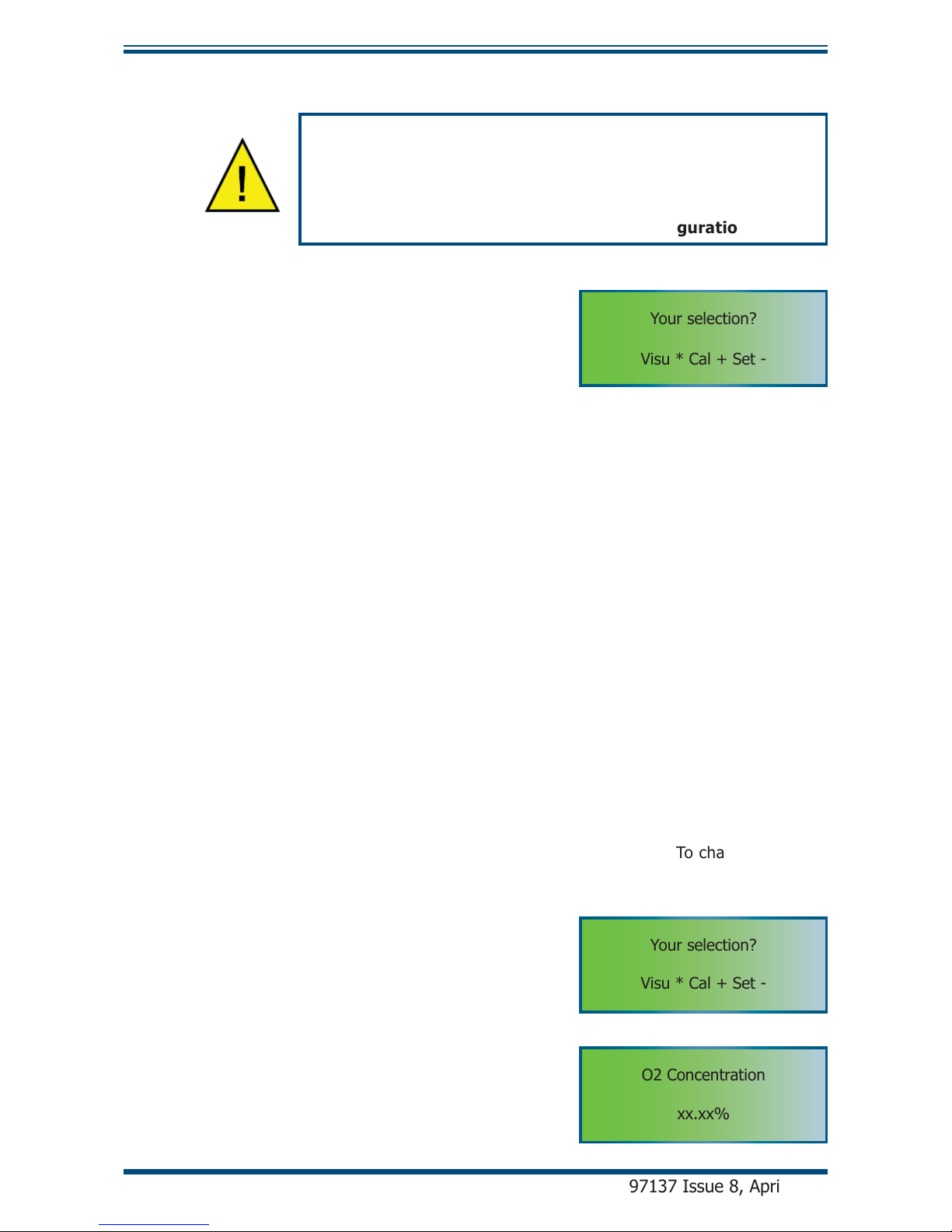
O2 Concentration
xx.xx%
Figure 6
Main Display
The instrument display is divided into two lines. The upper line is the descriptive line
and the bottom line displays the measured values or the function keys.
Page 13
XZR500 User’s Manual
Michell Instruments 5
INTRODUCTION
The function keys are located below the display and are used to select operations
from the main menu level, to enter sub-menu levels and to select and enter parameter
variables within those menu levels. The function key panels are shown in
Figure 5
and
Table 1 describes the operation of the keys.
Key Function
[*] Enter or select key. Operation of this key from the front-page display causes
the selection menu to be displayed
[+] Value up key. Used to change the value. Access key to the Calibration menu
[-] Value down key. Used to change the value. Access key to the Set-up menu
Table 1 Control Keys
The analog output signal can be set in 0-20 mA or 4-20 mA. The scale is confi gurable
in the range of 0.01-25% O
2
.
The system provides three alarms on relay contact: a general failure alarm and two
threshold alarms with user-confi gurable set-point (action high and low) and hysteresis.
Figure 7
Control Unit
Cable
The cable connecting the control unit and the probe supplies the furnace with power
and it relays the MSRS temperature and voltage measurements to the Control Unit.
The standard cable length is 6 meters long (optional, up to 100 meters).
Page 14

XZR500 User’s Manual
6 97137 Issue 8, April 2017
INTRODUCTION
1.3 Specifi cations
1.3.1 General
• Microcontroller: Motorola 68HC12
• Inlet converter: analog, 16 bits resolution, 0.0015% linearity error,
with fi lter and embedded calibrator
• Outlet converter: analog, 12 bits resolution, ±1 bit linearity error
• Display resolution: 0.1% O
2
(or 0.01 % on request and during
calibration)
• The 3-button keypad and digital interface allow:
Reading
Continuous display of the oxygen concentration to one decimal place (option
of second dp). Other parameters available through the HMI are Furnace
Temperature, Thermocouple Junction Temperature, MSRS Voltage and
Ambient Pressure (in mbars), if the optional pressure sensor is ordered.
Confi guration
Confi guring of the test gas value, activation direction of the alarms (high
or low) and hysteresis level, the fail safe value (output value sent by the
electronics in case of general failure), language (English, French or Italian),
the output analog signal, the associated scale and the factory settings. (For
other parameters see specifi c Appendix.)
• Output signal: 0-20 mA or 4-20 mA (user-selectable) galvanic isolation
(500 V), linear and programmable, output range can be selected between
0.01% and 25% O
2
• Output impedance: > 1 k Ω
• Alarms: contacts are normally closed, dry and potential-free, the cutting
power is max. 10 W (up to 100 V or up to 0.5 A):
1. General failure alarm warning of furnace under temperature (20°C
below the instruction), thermocouple separation, problems with
RAM backup after a re-set or adjustment error
2. Threshold alarms, with programmable activation direction and
hysteresis
• Consumption: 110 VA
• Ingress and impact protection:
Electronic enclosure: IP52 and IK05
Probe: IP53 and IK05
• Storage temperature: between -10 and +70°C
Page 15

XZR500 User’s Manual
Michell Instruments 7
INTRODUCTION
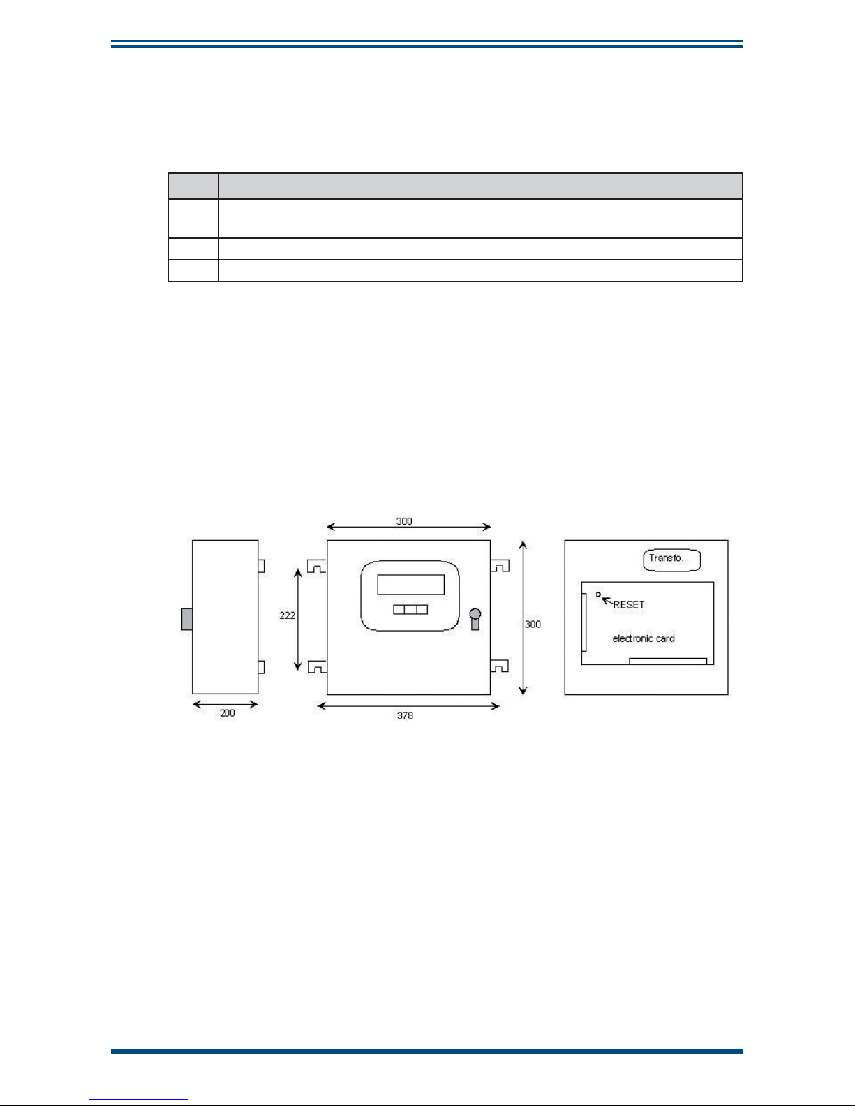
• Dimensions (mm):
Control Unit: 300 x 300 x 200 (w x h x d)
Sensor Head: 135 x 290 x 670 (w x h x d) (standard model)
Probe: 400, 600 or 900mm in length, with an outer diameter of 40mm
• Weight:
Control Unit: Approximately 7 kg
Sensor Head: Approximately 3 kg
Probe: Approximately 2-6 kg (dependant upon length & material of
construction)
• Power requirements: 230 or 115 V, -15%/+10%, 50/60 Hz
• Operating ambient temperature and moisture:
Temperature from 0 to 55°C
Relative moisture from 5% to 90% (non-condensing)
• Maximum temperature of the sample gases (Table 2):
Model Tubing Materials Gas Properties
XZR500 /SS 304 L stainless steel Tmax = 700°C
XZR500 /IL Inconel 600 Tmax = 1000°C
XZR500 /HR HR160 Tmax = 1000°C and corrosive gases
XZR500 /HC Hastelloy C2000 Tmax = 600°C and corrosive gases
XZR500 /CC Ceramic Tmax = 1300°C
XZR500 /HL Halar coating Tmax = 150°C
Table 2 Maximum Temperature of Gases
• Minimum speed of the sample gases: 0.5 m/s
Page 16

XZR500 User’s Manual
8 97137 Issue 8, April 2017
INTRODUCTION
1.3.2 Optional Equipment
• Tubular counter-fl ange for fi xing the probe to the stack (see Appendix G)
• Flange insulation (to prevent condensation forming)
• Extra length of cable (up to 100 meters)
• Calibration and verifi cation kit
• Back fl ushing system: for cleaning the probe tubes when fl ue gases are
very dusty (see Appendix E)
• Flue gas ejector system with heating (see Appendix F)
• Rear insulation
1.3.3 Options
• Self-calibration
• 115 V / 60 Hz power supply
• RS232 interface (see Appendix B)
1. Transmits all data straight from/to a computer terminal, i.e: O
2
concentration, furnace temperature, MSRS voltage, ambient
temperature and pressure.
2. Allows the setting of test gas value and starting the analyzer
calibration sequence.
3. Allows the changing of the alarm type, level and hysteresis, the
fail safe value, setting of the furnace temperature, the upper
scale adjustment, the signal output and scale, and starting the
self cleaning.
Page 17
XZR500 User’s Manual
Michell Instruments 9
INSTALLATION
2 INSTALLATION
2.1 General Mounting Precautions
• Place the probe as close as possible to the process (without breaching
the fl ame front).
• Prevent ambient air from entering the stack upstream or at the probe
tapping point and interfering with the measurement. Make sure all the
gaskets are placed and tightened
(Figure 4)
, and tighten-up the SS plug
for calibration gas inlet (
Figure 4
(15)).
NOTE: The stainless steel plug - or any 1/8” sealing ferrule -
should be tightened up by hand and then tightened again using a
7/16” spanner, turning only 1/8th of a turn so as not to damage
the connection.
• Avoid placing the probe near cleaning devices or elements that create
vibrations and are liable to disturb the measurement.
• Voltage should be applied to the analyzer immediately after the instrument
is fi xed on the stack so that the furnace can start heating. This will avoid
condensation at cold points where dirt could aggregate and clog up the
probe tubes. For the same reason, we recommend leaving the analyzer
powered up 24 hours a day, 365 days a year.
• The part of the tubing situated between the stack and the probe head
should be very well insulated - or even heated. If necessary, Michell
Instruments can manufacture a complete insulating cover for the outside
part of the probe (optional).
NOTE:
Ceramic probes require special handling.
Please read the following note carefully.
Ceramic Probes:
Special care must be taken when handling ceramic probes due to their fragile
nature. Inspect the probes thoroughly before inserting into stack. If they
have been damaged in transit, contact your Michell offi ce or distributor
immediately and inform them of the situation. Take photographic evidence
of the damage to the probe, and of the packaging, on the day of delivery.
On insertion ensure that the probe does not impact with the side of the orifi ce.
Once installed, it is not recommended to remove the probe. If removal is
unavoidable due to maintenance, then allow the probe several hours to fully
cool to ambient temperature and extract slowly.
Consideration for placement of the probe is essential. Avoid the fl ame front,
violently turbulent sections of the duct/fl ue, proximity to dampers, or where
falling refractory could strike the probe. Excessive vibrations must be avoided
as ceramic is a brittle material.
Incorrect handling or placement of the probe will invalidate the warranty.
Page 18
XZR500 User’s Manual
10 97137 Issue 8, April 2017
INSTALLATION
2.2 Probe Mechanical Installation
f. Inner probe tube
3 marks to indicate
the bevelled edge
Horizontal line
Bevelled edge
e. Probe head
d. Gasket for flange
c. Outer tube
b. Gasket for flange
a. Tubular
counter flange
Gas Inlet hole
}
}
}
5°
}
}
}
}
}
}
}
h. Locking ring
i. Rear nut
g. Gasket for locking ring
}
}
}
}
}
Gasket
Nut
}
}
j. Gasket
Figure 8
Probe Installation
The XZR500 is simple to set-up. Follow the instructions below:
1. Weld the tubular counter-fl ange (a) onto the stack. Follow the orientation
shown below to ensure that the probe head is set in a vertical position.
Slope the tubular counter-fl ange (a) slightly (maximum 5 degrees) so that
condensed water can go back to the process. The probe is fi tted with a PN6
DN15 type fl ange (4 x 11mm diameter holes, placed on a 55mm diameter
circle). Pay special attention to the orientation and slope especially if the
counter fl ange/nozzle with fl ange is provided by the customer.
055mm
055mm
055mm
9
88
5°
Figure 9
Probe Head Orientation
Page 19
XZR500 User’s Manual
Michell Instruments 11
INSTALLATION
2. Place the outer probe (c) with the fl ange gasket (b) according to the
drawing in
Figure 8
. The gas inlet hole should face the process fl ow.
Process ow
Gas inlet
hole
Process ow
Gas inlet
hole
Figure 10
Flange Gasket Orientation
3. Mount the probe head (e) with the fl ange gasket (d) on to the tubular
counter-fl ange (a). Secure the tubular counter fl ange, fl ange for outer
tube and fl ange of the probe head together by secure nuts onto four bolts
on the counter fl ange.
e. Probe head
d. Gasket for flange
b. Gasket for flange
a. Tubular
counter flange
Figure 11
Tubular Counter Flange Position
Page 20
XZR500 User’s Manual
12 97137 Issue 8, April 2017
INSTALLATION
4. Place the gasket onto the inner tube (f) and insert into the probe head
(e) (see
Figure 8).
Make sure the bevelled edge of the inner tube tip
faces the opposite direction to the gas inlet hole on the outer tube (c) as
shown below. There are three marks on the other end of the inner tube
to indicate the orientation of the bevelled edge (see
Figure 12).
Process ow
f. Inner tube
c. Outer tube
Bevelled edge
Gas inlet hole
Figure 12
Inner Tube Orientation
5. Place the locking ring (h) with the locking ring gasket (g), the rear nut
(i) and the inner tube gasket (j) accordingly on the rear of the probe
head. (See
Figure 8)
6. Put insulation between process and the probe head if necessary.
If the back fl ush option is chosen, then the orientation
must be reversed. This is because the inner tube becomes
the inlet so any dust build up will happen in the inner
tube. When the back fl ush is operated, it clears the tube
more effi ciently.
Page 21
XZR500 User’s Manual
Michell Instruments 13
INSTALLATION
2.3 Control Unit Mechanical Installation
The Control Unit is supplied with lugs for fi tting on the wall (see
Figure 7).
2.4 Wiring
Only authorized personnel should open the control unit.
Take all precautionary measures to avoid accidents
related to electrostatic shocks.
2.4.1 Cable Specifi cations
The standard analyzer is supplied with 6 meters of cable. Longer cable lengths are
available up to 100 meters. The electrical connections are as follows:
brown
} 2 wires to supply the power to the furnace
brown
green (+)
} 2 wires for measuring the thermocouple voltage
white (-)
blue (reference)
} 2 wires for measuring the MSRS voltage
red (measurement)
Table 3 Cable Specifi cations
The wires should be stripped to 8mm at each end. There is a ground wire at one end of
the supplied cable. This end should be connected to the Control Unit.
2.4.2 Connection of the Cable (supplied) to the Control Unit
Connect the supplied cable - using the end with 7 wires (including ground wire) - as
follows:
NC
+TC (green)
-TC (white)
Ref. 0
2
(blue)
Meas. 0
2
(red)
+mA Output
-mA OutputNCNC
NC
Furnace power brown
Furnace power brown
General fault alarm
General fault alarm
Alarm 1
Alarm 1
Alarm 2
Alarm 2NC230 N
Vac P
Earth
29 30 31 32 33 34 35 36 37 38 39 40 41 42 43 44 45 46 47 48 49 50
From the sensor
to the
sensor
(furnace)
to the Mains
0/4-20mA
Output
J4 Left connector: measurement
J5 Right connector: power and alarms
CABLE
(supplied)
Table 4 Connection of the Control Unit
Both the ground wire of the supplied cable and the earth wire from the mains must
be connected to the copper bar near the cable gland.
Page 22

XZR500 User’s Manual
14 97137 Issue 8, April 2017
INSTALLATION
2.4.2.1 Connection to the Mains
Use shielded cable (2 x 1.5mm² max.) that is terminated appropriately. Follow the
Table 4 wiring diagram (pins 48, 49 and 50).
Connect both the screen and the earth wire to the copper bar near the cable gland.
2.4.2.2 Connection of the 0/4-20 Output
We suggest that shielded cable (2 x 0.75mm²) is used and terminated appropriately.
Follow the Table 4 wiring diagram (pins 34 and 35).
Connect the braid to the copper bar near the cable gland.
2.4.2.3 Connection of the Alarms
We suggest that shielded cable is used and terminated appropriately. Follow the Table
4 wiring diagram (pins 41 to 46).
Connect the screen and the earth wire to the copper bar near the cable gland.
2.4.3 Connection of the Cable to the Sensor Head
Unscrew the three hex head screws at locations shown below to open the case of the
XZR500 probe head and access the terminal block.
Figure 13
Hex Screw Locations
Page 23
XZR500 User’s Manual
Michell Instruments 15
INSTALLATION
Connect the end of the cable - using the end with 6 wires - according to the
Figure 14
wiring diagram.
Ref. -TC +TC M F F
Blue
___________
White
___________
Green
___________
Red
___________
Brown
___________
Brown
___________
Blue
White
Green
Red
MSRS
Furnace
Supplied Cable
probe
connector
Figure 14
Probe Wiring Diagram
Page 24
XZR500 User’s Manual
16 97137 Issue 8, April 2017
OPERATION
3 OPERATION
The MSRS is a fragile element - keep the sensor free from any
shock. Any measurements that need to be done at the MSRS
terminals must be done very carefully in order to prevent
irreversible damage to the sensor.
NEVER attempt to measure the resistance between the MSRS
reference terminal and another terminal
Use a voltmeter with impedance >1000 MΩ for measuring
the voltage between the MSRS measurement and reference
terminals
3.1 Outputs
3.1.1 Analog Output
The output signal is selectable to be either 0-20 mA or 4-20 mA.
The range is selectable between 0 and 25%.
3.1.2 Alarms
The system has 3 alarm contacts:
• 1 general failure alarm warning of furnace under temperature (20°C
below the set temperature), thermocouple separation, problem with RAM
backup after a re-set or adjustment error.
• 2 threshold alarms, with programmable activation direction and hysteresis.
The activation of a threshold alarm can be identifi ed when the corresponding green LED
turns off on the Control Unit.
The activation of the general fault alarm can be identifi ed when all the three green LEDs
turn off on the Control Unit.
The contacts are normally closed, dry and potential-free. The maximum switched load
is 10 W for each contact (up to 100 V or up to 0.5 A).
Page 25

XZR500 User’s Manual
Michell Instruments 17
OPERATION
3.2 Start-Up
After fi nishing and verifying the connections, power up the analyzer.
Oven Temperature
Low alarm /xxx.x
During warm-up, the display shows:
The measured temperature value alternates with the message "Low alarm" during one
second in every two seconds.
When the temperature is within 30°C of the required temperature (after about 15
minutes), the system calculates the oxygen concentration and the result will appear on
the display.
O2 Concentration
xx.xx %
Then the following default message appears:
Page 26
XZR500 User’s Manual
18 97137 Issue 8, April 2017
OPERATION
3.3 Display, Confi guration and Adjustment
During confi guration there is no data communication
between the Control Unit and the Sensor Head
and this could disturb the stability of the furnace
temperature. Make sure that the furnace temperature
is stable before confi guration and allow the analyzer’s
temperature to stabilize after confi guration.
Your selection?
Visu * Cal + Set -
To display the main selection menu, press and
hold the [*]
Enter key until the menu appears.
You can now select the option you need by
pressing one of the following keys:
[ *
] Enter key cycles displayed parameters
[ - ] Minus key to enter the set-up mode
[ + ] Plus key to enter the calibration mode
3.3.1 Visualization Menu [*]
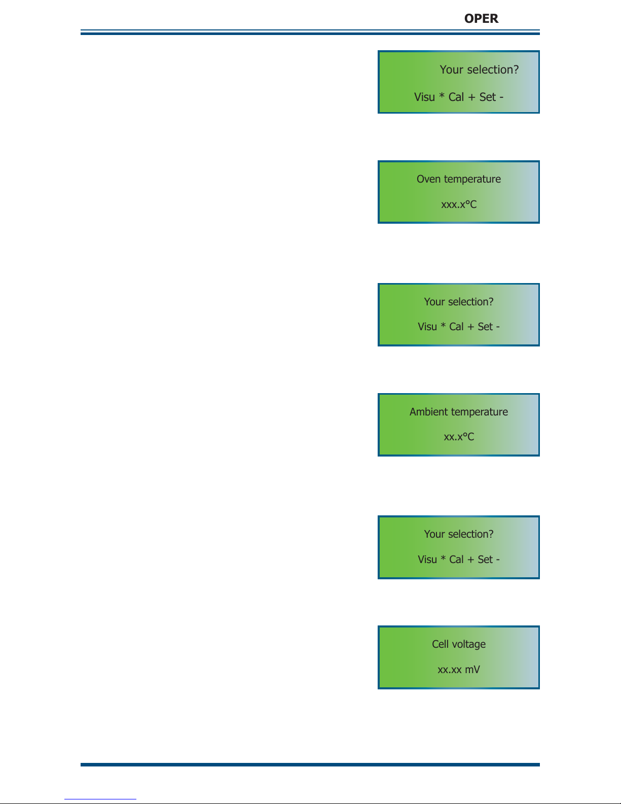
The visualization menu displays the following parameters:
• O2 concentration
• Oven temperature in °C
• Temperature of the thermocouple cold junction in °C (ambient temperature)
• MSRS voltage
• Pressure value
Proceed as described above to enter the main selection menu. To scroll through the
parameter list use the [*]
Enter key as shown below.
It is not possible to change any values in the visualization menu. To change values go
to the set-up menu.
Your selection?
Visu * Cal + Set -
1. From the main menu, press and hold the
[*]
Enter key until the main selection
menu appears
O2 Concentration
xx.xx%
2. Press the [*] Enter key from the main
selection menu to show the fi rst parameter:
O
2
concentration
Page 27
XZR500 User’s Manual
Michell Instruments 19
OPERATION
Your selection?
Visu * Cal + Set -
3. Press and hold the [*] Enter key again to
re-enter the main selection menu
Oven temperature
xxx.x°C
4. Press the [*] Enter key from the main
selection menu to show the second
parameter: Oven temperature
Your selection?
Visu * Cal + Set -
5. Press and hold the [*] Enter key to reenter the main selection menu
Ambient temperature
xx.x°C
6. Press the [*] Enter key from the
main selection menu to show the third
parameter: Ambient temperature
Your selection?
Visu * Cal + Set -
7. Press and hold the [*] Enter key to reenter the main selection menu
Cell voltage
xx.xx mV
8. Press the [*] Enter key from the main
selection menu to show the fourth
parameter: Cell voltage
Page 28
XZR500 User’s Manual
20 97137 Issue 8, April 2017
OPERATION
Your selection?
Visu * Cal + Set -
9. Press and hold the [*] Enter key to reenter the main selection menu
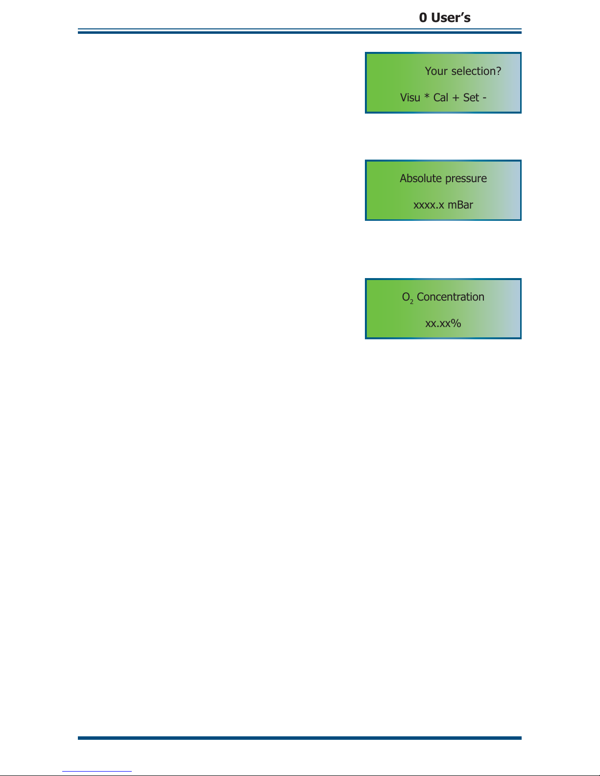
Absolute pressure
xxxx.x mBar
10. Press the [*] Enter key from the main
selection menu to show the fi fth parameter:
Absolute pressure
O2 Concentration
xx.xx%
11. Repeating the process again will return
to the default displayed parameter: O2
concentration
NOTE: If you do not press the [*]
Enter key within 30 seconds, while showing
one of the parameters, the display will automatically return to the default
display of O2 concentration.
Page 29

XZR500 User’s Manual
Michell Instruments 21
OPERATION
3.3.2 Set-up [ - ]
The set-up mode is used for changing system control parameters, each of which are
selected from the set-up confi guration table. There are two different sets of setting
parameters. Quick settings are accessible under code 0.12, while advance settings are
accessible under access code 0.20.
Access
Code
Function Default
Setting
Unit Remarks
0.12
Std confi g. 0.30 0.00 N/A
Resets the system to standard confi guration.
The default confi guration is restored. The
current parameters will be deleted. Usually
necessary after replacement of the micro
controller card. Do not change without
consulting factory
Test gas value 8.00 % Sets the value of the calibration gas
Type Alarm 1 2.00 N/A
Sets alarm type. If value >1.00 high Alarm 1,
if value <1.00 low Alarm 1
Level of Alarm 1 30.00
% of the
measurement range
Sets process trigger point for Alarm 1
Type Alarm 2 2.00
Sets alarm type. If value >1.00 high Alarm 2,
if value <1.00 low Alarm 2
Level of Alarm 2 30.00
% of the
measurement range
Sets process trigger point for Alarm 2
Hysteresis 1.00
% of the
measurement range
Sets relay hysteresis
Fail safe value 0.00
% of the output
scale
Sets the fault alarm. If released, the output
signal switches to the selected value
0.20
Oven temp set
pt
700.00 °C
Sets the oven temperature. Do not change
without consulting factory
Francais
English
Italiano
English N/A Sets display language
Offset room
temp
3.00 N/A
Sets the offset set point for the MSRS T/C cold
junction. Do not change without consulting
factory
Room temp.
grad.
10.00 N/A
Sets the span set point. Do not change without
consulting factory
High adjust 0.00 Adjusts reading near 21%
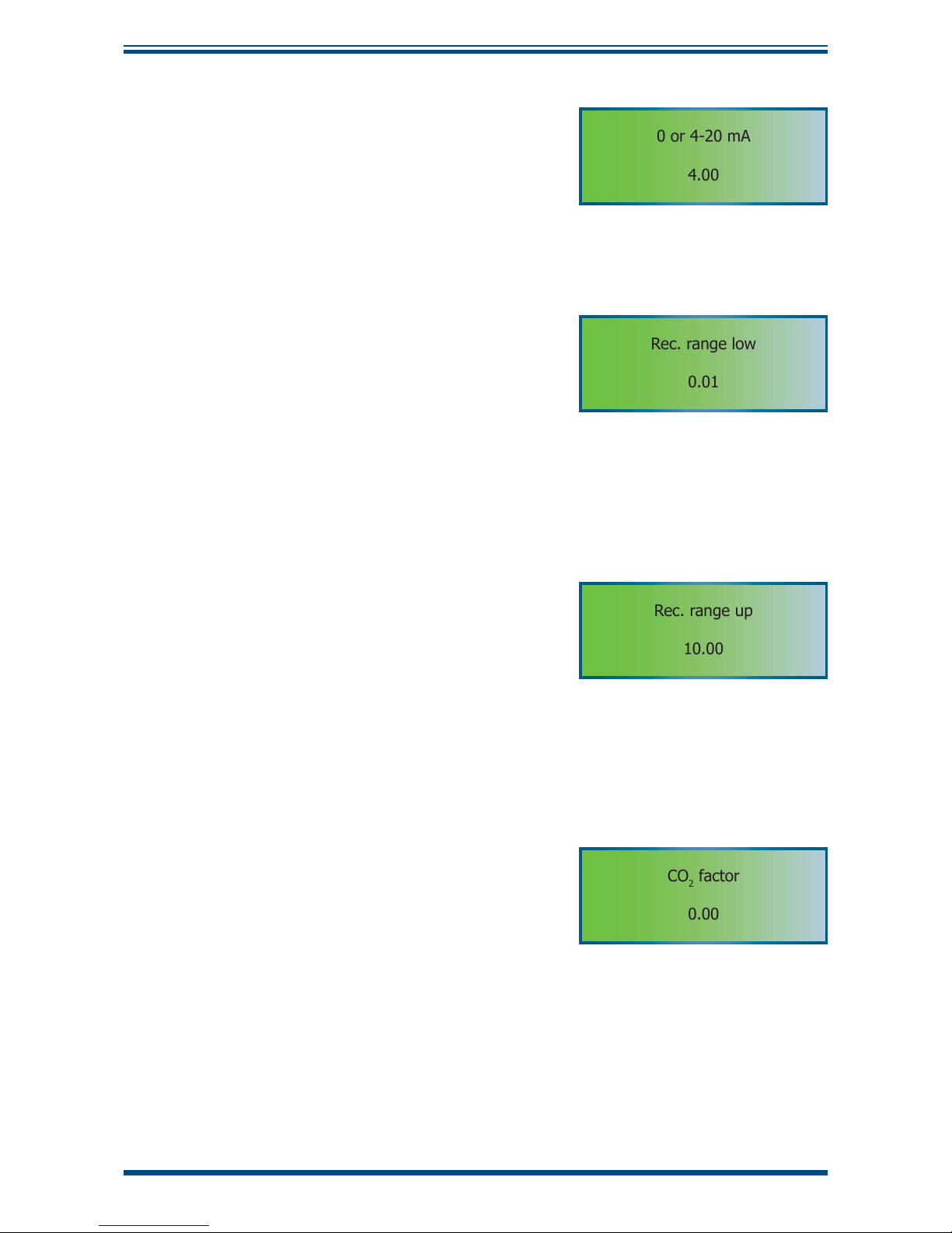
0 or 4 - 20 mA
output
4.00 N/A Sets the analog output signal
Rec. range low 0.01 % Sets the measuring range lower limit
Rec. range high 10.00 % Sets the measuring range higher limit
CO2 factor 0.00 % Enter the CO2 value
Gr 10.00
Factory setting. Do not change without
consulting factory
Ti 10.00
Factory setting. Do not change without
consulting factory
Offset pressure Pre-set mbar
Sets the offset pressure. Do not change
without consulting factory
Absolute
pressure
Pre-set mbar
Sets the absolute pressure. Do not change
without consulting factory
Cell cleaning Start the cell self-cleaning process
Table 5 Access codes 0.12 & 0.20
Page 30

XZR500 User’s Manual
22 97137 Issue 8, April 2017
OPERATION
3.3.2.1 Access code 0.12 - quick settings
Your selection?
Visu * Cal + Set -
From the main menu page, press and hold the
[*]
Enter key until the main selection menu
appears.
Access code?
0.12
Press the [–] (Set-up menu) from the main
selection menu to show the Access code page.
Using the [–] and [+] keys enter the 0.12 code
to access the quick settings and press the [*]
Enter key to confi rm the selection.
Standard Confi guration
Std confi g. 0.30
0.00
The fi rst page under access code 0.12 is
for restoring the factory default standard
confi gurations.
A standard confi guration should be restored after replacing the microcontroller
card.
Consequences: All the parameters change to the default value. The analyzer
is no longer calibrated.
DO NOT change the value from 0.00 without consulting the
factory. Restoring to standard confi guration will change all the
parameters of the last set-up. Make sure you note down all
parameter values before executing the operation. After re-set
the analyzer is no longer calibrated.
If a standard confi guration is not necessary leave the value as 0.00 and press the [*]
Enter key to go to the next page.
If a standard confi guration is necessary, enter 0.30 and press the [*]
Enter key to
activate the restoring process.
Calibration gas value
Test gas value
8.00
This page shows the current calibration gas
value. Use the [+] and [–] keys to modify the
value and press the [*] Enter key to confi rm the
selection and move to the next parameter.
NOTE: This value is in %. For example,
8.00 equals 8%.
Page 31
XZR500 User’s Manual
Michell Instruments 23
OPERATION
Alarm 1
Type Alarm 1
2.00
1. The ‘type of alarm’ screen is used to setup the direction for the Alarms 1 and 2
to the values ‘High’ and ‘Low’. The ‘High’
alarm will be activated when increasing
the signal value to above the set-point
level. The ‘Low’ alarm will be activated by
decreasing the signal value to below the
set-point level.
Values higher than 1.00 indicate that the alarm type will be ‘High’. Values lower than
1.00 indicate that the alarm type will be ‘Low’. Press the [+] and [–] keys to modify
the value. Press the [*]
Enter key to confi rm the selection and move to the next
parameter.
High Alarm 1
2.00
2. Depending on the selection in step 1, the
next page shows High/Low set-point of
Alarm 1. Press the [+] and [–] keys to
modify the set-point and press the [*]
Enter key to confi rm the selection and
move to the next parameter.
NOTE: If the alarm is set as Low alarm this page will display ‘Low Alarm 1’
accordingly
NOTE: This set-point value is in %. For example, 2.00 equals 2%. The value
can be set between 0 and 200%.
Alarm set-point = (alarm level/max value of the scale) x 100
Example 1:
Selected range is 1-1,000 ppm.
The desired alarm is at 600 ppm.
Calculation:
%= (600 ppm*100)
/1000 ppm = 60
The set value has to be 60 as
600ppm represents 60% of
the range
Example 2:
Selected range is 10-10,000 ppm.
The desired alarm is at 600 ppm.
Calculation:
%= (600 ppm*100)
/10,000 ppm = 6
The set value has to be 6 as
600ppm represents 6% of the
range
Example 3:
Selected range is 1 ppm to 25%
logarithmic. The desired alarm is
at 600 ppm.
Calculation:
%= (600 ppm*100)
/250,000ppm = 0.24
The set value has to be 0.24
as 600ppm represents 0.24%
of the range
Table 6 Alarm Set-Point Examples
Alarm 2
To confi gure Alarm 2, repeat steps 1 and 2 as shown in Alarm 1.
Page 32

XZR500 User’s Manual
24 97137 Issue 8, April 2017
OPERATION
Alarm hysteresis
Relay hysteresis
0.10
This page shows the value for the relay hysteresis
that is expressed in percentage oxygen. Press
the [+] and [–] keys to adjust the value. Press
the [*]
Enter key to confi rm the selection and
move to the next parameter.
Fail safe value
Fail safe value
0.00
This page shows, in percentage, the fail-safe
value of the measurement range. This is the
percentage value that the 4-20 mA output will
go to under fault conditions. E.g. 100.00 means
the output will be 20mA (100%) under fault
conditions.
Press the [+] and [–] keys to adjust the value.
Press the [*]
Enter key to confi rm the selection.
The Access code page will appear.
3.3.2.2 Access code 0.20 - advanced settings
Access code?
0.20
At the Access code page, use the [–] and [+]
keys to enter the 0.20 code to access the
advance settings and press the [*]
Enter key to
confi rm the selection.
Oven temperature set-point
Oven temp set pt
700.00
This fi rst page under access code 0.20 is used
to set the temperature of the sensor oven.
CAUTION: Do not change the value without
consulting the factory.
Press the [*] Enter key to move to the next
parameter.
Languages
English ?
No * Yes -
English, French or Italian can be selected as the
display language. There are separate pages for
each language.
Press the [*]
Enter key to stay with the current
language in use
French ?
Non * Oui -
Press the [–] key to change to the chosen
language
Italiano ?
No * Si -
Page 33

XZR500 User’s Manual
Michell Instruments 25
OPERATION
Offset compensation MSRS cold junction
Offset room temperature
3.00
This page shows the offset value for
compensation of the MSRS thermocouple cold
junction. The value is factory pre-set and may
vary for individual analyzers.
CAUTION: Do not change the value without
consulting the factory.
Press the [*]
Enter key to move to the next
parameter.
Span compensation MSRS cold junction
Room temp. grad.
10.00
This page shows the span value for compensation
of the MSRS thermocouple cold junction.
The value is factory pre-set and may vary for
individual analyzers.
CAUTION: Do not change the value without
consulting the factory.
Press the [*]
Enter key to move to the next
parameter.
High Adjust
High adjust
2.00
This page shows the ‘High adjust’ function that
allows the user to adjust the reading around
21% oxygen. The value is factory pre-set and
may vary for individual analyzers.
NOTE: The value is factory pre-set. It can
be changed when different calibration is
required.
After a calibration, let the air circulate
for approximately 15 minutes, and then
adjust this value to give a 21% oxygen
reading. If the calibration is done with air,
set the value to 0.00.
The equation to calculate the high adjust is:
HA = ((20.9 - O2reading) /O2 reading) * 100
e.g. If the analyzer display is 20.4%
HA = ((20.9 - 20.4) / 20.4) * 100 = 2.5
Press the [+] and [–] keys to adjust the value.
Press the [*]
Enter key to confi rm the selection
and move to the next parameter.
Page 34
XZR500 User’s Manual
26 97137 Issue 8, April 2017
OPERATION
Output Signal
0 or 4-20 mA
4.00
This page shows the available current ranges
for the signal output. Enter 0.00 for 0-20 mA
and 4.00 for 4-20 mA. Press the [+] and [–]
keys to adjust the value. Press the [*]
Enter
key to confi rm the selection and move to the
next parameter.
Measurement range – lower limit
Rec. range low
0.01
This page shows the selected lower limit of the
measurement range. Press the [+] and [–] keys
to adjust the value. Press the [*]
Enter key
to confi rm the selection and move to the next
parameter.
NOTE: This value is in %. For example,
0.01 equals 0.01% O2.
Measurement range – upper limit
Rec. range up
10.00
This page shows the selected upper limit of the
measurement range. Press the [+] and [–] keys
to adjust the value. Press the [*]
Enter key
to confi rm the selection and move to the next
parameter.
NOTE: This value is in %. For example,
10.00 equals 10% O
2
.
CO
2
factor
CO2 factor
0.00
This page is used to enter the CO2 maximum
theoretical value of the fuel gas for CO
2
calculation. Press the [+] and [–] keys to adjust
the value. Press the [*]
Enter key to confi rm
the selection and move to the next parameter.
(See Appendix C)
Page 35

XZR500 User’s Manual
Michell Instruments 27
OPERATION
Gr value
Gr
10.00
This value is for factory settings only.
CAUTION: Do not change the value without
consulting the factory.
Press the [*]
Enter key to move to the next
parameter.
Ti value
Ti
10.00
This value is for factory settings only.
CAUTION: Do not change the value without
consulting the factory.
Press the [*]
Enter key to move to the next
parameter.
Offset pressure
Offset pressure
8.00
This page displays the offset pressure. The value
is factory pre-set and may vary for individual
analyzers.
CAUTION: Do not change the value without
consulting the factory.
Press the [*]
Enter key to move to the next
parameter.
Absolute pressure
Abs. pressure
11.00
This page displays the absolute pressure.
The value is factory pre-set and may vary for
individual analyzers.
CAUTION: Do not change the value without
consulting the factory.
Press the [*]
Enter key to move to the next
parameter.
Page 36

XZR500 User’s Manual
28 97137 Issue 8, April 2017
OPERATION
Cell self-cleaning
Cleaning cell
0.00
This function allows the analyzer to self-clean
the sensor cell. The cleaning process lasts for
one hour. The furnace is heated to 780°C in
order to clean itself and the MSRS. Remove the
inner probe tube to make the self-cleaning more
effi cient.
NOTE: During self-cleaning, the output
signal will be locked at the fail-safe value
If cell cleaning is not required, leave the value
at 0.00 and press the [*]
Enter key to skip this
procedure and go back to the default display.
If cell cleaning is required, press the [+] and [–]
keys to adjust the value to 0.10 and press the
[*]
Enter key to start the process. The following
messages will appear:
Temperature Oven
Low alarm
Cleaning cell
End of control?
The process can be stopped by pressing and
holding the [*]
Enter key or it will stop
automatically after the above 60 minute process
is completed. Once the cleaning process is
fi nished the furnace will start to cool down.
Cleaning cell
60 min
After about 10 minutes the temperature will
return to the set temperature.
Cleaning cell
cooling
Cleaning cell
10 min
Temperature Oven
xxx.x°C
Page 37

XZR500 User’s Manual
Michell Instruments 29
OPERATION
3.3.3 Calibration [+]
The XZR500 has been designed for simple operation. The calibration procedure is
extremely easy and can be performed within minutes. The analyzer is self-adjusting
during calibration. There are only a few steps that need to be carried out for the actual
calibration procedure.
3.3.3.1 Recommended Calibration Gas
NOTE: Please make sure that only gas of a known composition is used for
calibration of the XZR500. The gas cylinder must be certifi ed as to the exact
composition of the calibration gas.
Michell recommends the following calibration gas concentrations that can be ordered
from your analyzer vendor.
• 1G Calibration Kit with one gas cylinder (nitrogen with 8% oxygen
concentration)
• 2G Calibration Kit with two gas cylinders (nitrogen with 8% oxygen
concentration for calibration and nitrogen with 2% oxygen concentration
for verifi cation)
CALIBRATION GAS UNCERTAINTY:
Observe the uncertainties of the calibration gas when
calculating the overall analyzer uncertainty. Any uncertainty
of the oxygen content of the calibration gas may introduce
considerable error in the calibration of the analyzer.
NOTE: Prior to calibration, make sure that the ‘Test gas value’
in the access code 0.12 of the analyzer menu is the same as
the calibration gas value.
3.3.3.2 Regulating the Calibration Flow Rate
In order to perform the calibration it is recommended to arrange a temporary connection
with a regulator and isolation valve located at the calibration gas inlet on the analyzer.
Make sure the connection is as short as possible. A regulator and isolation valve are
supplied in the calibration kit.
Connect the calibration kit or your test gas cylinder to the calibration gas inlet
(Figure
4 (12))
. Use 1/8” tube and fi tting. NOTE: Ensure a fl ow of 7 l/hour (±2 l/hour)
(0.12 to 0.18 l/min).
NOTE: Tighten up the stainless steel locking nut by hand and then tighten again
using a 7/16" spanner, for 1/8th turn so as not to damage the connection.
NOTE: During calibration the output signal is frozen at the last value measured
before the beginning of the calibration procedure.
Page 38

XZR500 User’s Manual
30 97137 Issue 8, April 2017
OPERATION
3.3.3.3 Calibration Procedure
Follow Sections 3.3.3.1 and 3.3.3.2 to connect the calibration gas to the analyzer (8%
oxygen bottle, if 1G or 2G is ordered). Do not switch on the calibration gas fl ow at this
time.
Your selection?
Visu * Cal + Set -
1. From the main page, press and hold the
[*] (Enter key) until the main selection
menu appears.
Test gas value
8.00
2. Press the [+] key from the main selection
menu to enter the calibration mode. The
fi rst page displays the ‘Test gas value’.
Make sure that the displayed value is the
same as the calibration gas.
NOTE: This value is in %. For
example, 8.00 equals 8%.
If the displayed value is not the same value
as the calibration gas, exit the calibration
mode from next page (‘Inject gas’) and
then go to ‘Test gas value’ under ‘Setup menu’ Access code 0.12 to adjust it.
(Please refer to details in Section 3.3.2.1)
Press the [*] (Enter key) to move to the
next page.
Inject gas
Yes* No -
3. This page shows the calibration start
command.
[*] – Starts the calibration process (go to
step 4)
[–] key – Cancels the calibration process
and exits the calibration mode. If the ‘Test
gas value’ needs to be modifi ed, then go
to ‘Test gas value’ under ‘Set-up menu’
Access code 0.12 to adjust it.
NOTE: Once the calibration process
starts (after pressing the [*] key),
the 4-20 mA output will be frozen
from this step until the end of the
purge procedure and will show the
last measured value.
4. Open the test gas cylinder to introduce
the gas into the analyzer. Adjust the fl ow
to the recommended level of 7 l/hour (±2
l/hour) and ensure that the fl ow is stable.
Higher or lower fl ow rates could affect
the accuracy of the calibration as well as
further measurements.
Page 39

XZR500 User’s Manual
Michell Instruments 31
OPERATION
Adjustment sequence
xx.xx
5. The calibration process takes about 10
minutes. During calibration the screen
alternates, displaying two messages
- ‘running’ and the current value of
calibration.
Adjustment sequence
running
Press the [*] key to fi nish the calibration
once this value is stabilized, otherwise the
calibration process will end automatically
after the 10 minutes time limit is reached.
The screen will then change to the
following:
Control gas?
Yes* No -
6. After the calibration process the quality of
the calibration can be verifi ed by starting
the verifi cation process with a control gas.
Assure that the control gas has a different
oxygen concentration from the gas used
for calibration (e.g. 2% if the calibration
gas was at 8%). The Calibration kit with
both gases is available - order code 2G.
[*] key – continues with the verifi cation
process (go to step 7)
[–] key – skips the validation and
completes the calibration process (go to
step 8)
Control gas?
xx.xx
7. If the [*] key is pressed in step 6 this
screen is used to verify the calibration.
The page alternates between real-time
reading of the control gas and the option
to end the verifi cation.
Stop control?
Yes* No -
Introduce the control gas to the inlet of
the analyzer. The calibration can then be
verifi ed simply by comparing the reading
with the real oxygen content of the control
gas.
[*] key – Ends the verifi cation process and
moves to the next page
[–] key – No effect
Page 40

XZR500 User’s Manual
32 97137 Issue 8, April 2017
OPERATION
Stop gas?
Yes * No -
8. Once the verifi cation step is completed
or skipped, the screen shows ‘Stop gas?’
to remind the user to switch off the
calibration/control gas.
Confi rm the fi nish of the calibration with
the [*] key and move to next page.
The calibration/control gas should now be
switched off and, if necessary, the process
gas reconnected back to the analyzer.
[–] key – No effect
Adjustment sequence
Purge running
9. After the analyzer leaves the calibration
mode the screen alternates, displaying
two messages - ‘Purge running’ and
the real live measurement of the purge
(process) gas. This procedure cleans all
the calibration gas in the analyzer. It takes
about 3 minutes.
At the end of the purge the 4-20 mA
output will be released.
Adjustment sequence
xx.xx
10. The purging process can be stopped after
one minute. Press the [*] key and hold
until the default main page appears.
Fault
Calibration
If the following message is displayed the
analyzer calibration was not successful.
Press RESET
(Figure 7)
or press the [+]
and [–] keys to cancel the message.
This may occur when:
• The O2 concentration of the calibration
gas is different from the value set in
‘Set-up menu’ Access code 0.12. Go to
‘Test gas value’ under ‘Set-up menu’
Access code 0.12 to adjust it. (Refer to
details in Section 3.3.2.1).
• The MSRS is faulty. It should be
replaced.
Page 41
XZR500 User’s Manual
Michell Instruments 33
OPERATION
The test gas value cannot be modified at this point.
In order to modify it, quit the process from ‘Inject Gas?’
page and set it in Access code 0.12
- :
quit calibration sequence
The adjustment process lasts 10 minutes but
it can be stopped after 1 minute by pressing the [*] key
- :
No effect
- :
No effect
Purge sequence lasts 3 minutes but it can be stopped
after 1 minute by pressing the [*] key
Your selection?
Visu* Cal+ Set -
Inject gas?
Yes * No -
Control gas?
Yes * No -
Stop gas?
Yes * No -
Control Gas Stop control?
Value Yes * No -
d
d
+
Test gas value
8.00
*
*
d
d
d
Adjustment sequence
running/Value
(*)
d
d
*
d
d
Adjustment sequence
Purge running/Value
02 concentration
xx.x(x)%
*
(*)
*
d
d
d
-
Figure 15
Calibration Flow-Chart
Page 42

XZR500 User’s Manual
34 97137 Issue 8, April 2017
MAINTENANCE
4 MAINTENANCE
4.1 Preventative Maintenance - Cleaning
The XZR500 should be periodically cleaned. The frequency of cleaning will depend
upon your application.
• Identify the 3 orientation marks on the inner tube and remove it (
Figure
4
(23)).
• Clean the inside of the outer tube (
Figure 4
(2)) by moving the inner tube
backwards and forwards - the tip disk on the inner tube will sweep the
inside of the outer tube.
• Clean the inner tube with a long metal brush or abrasive cloth. It should
then be cleaned with hot water and afterwards have pressurized air blown
through the tube. Fit the inner tube of the probe back into the correct
position.
• Change the gaskets and tighten-up all the nuts frequently to prevent
contamination from outside air entering the stack.
• The probe should be removed at least once a year, e.g. during a factory
shutdown, to inspect the probe tubes. Clean them as necessary.
Page 43

XZR500 User’s Manual
Michell Instruments 35
MAINTENANCE
4.2 Replacement Of The XZR500 MSRS
• Remove the probe inner tube (
Figure 4
(23)).
• Turn off the analyzer and disconnect the power lead.
• Wait until the furnace and sensor housing cool down (at least 45 minutes).
• Remove the cover of the sensor housing.
• Disconnect the cable.
• Disconnect the sealing head (
Figure 4
(3)).
• Remove the MSRS (
Figure 4
(5)).
• Clean the sealing head if necessary.
• Re-insert the clean sealing head, the new MSRS (Ref 204 011) and new
o-rings (Ref 108 006) (see
Figures 17 and 18
).
• Replace the screws and tighten-up.
• Connect the MSRS and the cable according to the diagram (
Figure 16).
• Power up the analyzer.
• Wait for one hour.
• Re-fi t the probe inner tube.
• Set self-cleaning (0.10 code).
• Wait for few hours before calibrating the analyzer (see Section 3.3.3).
Figure 16
XZR500 MSRS Mounting Diagram
Page 44

XZR500 User’s Manual
36 97137 Issue 8, April 2017
MAINTENANCE
Figure 17
XZR500 Top View
Figure 18
XZR500 Side View
Page 45

XZR500 User’s Manual
Michell Instruments 37
MAINTENANCE
4.3 Replacement of the Furnace
• Remove the probe inner tube (
Figure 4
(23)).
• Turn off the analyzer and disconnect the power lead.
• Wait until the furnace and the sensor housing cool down (around 45 minutes).
• Remove the cover of the sensor housing.
• Disconnect the cable.
• Disconnect all the wires from the MSRS, the furnace and the connector block
(
Figure 4
(11)).
• Remove the MSRS (
Figure 4
(5)).
• Remove the sealing head (
Figure 4
(3)).
MSRS
O ring
Sealing
head
• Clean the sealing head if necessary.
• Loosen the probe mounting plate
fastener (
Figure 4
(19, 20)).
• Unscrew the corner plate (2 CHC
screws M6).
• Draw back the mounting plate.
• Remove the furnace.
• Place the new furnace (you may
have to enlarge the holes in the
corner plate to allow the furnace
wire’s terminals to pass).
• Replace the stop washers.
• Replace the corner plate.
• Bring the attachment plate close to the corner plate.
• Fasten the corner plate by pushing it down so that the lock washers lay against
the furnace upper cheek.
• Tighten up the probe mounting plate fastener.
• Re-insert the clean sealing head with the new MSRS (Ref 204 011) and new
o-rings (Ref 108 006) (CAUTION: the head of the MSRS (1) has to stop
against the bearing of the sealing head body (3)). (See
Figure 16.
)
• Connect the MSRS and the cable according to the diagram
(Figure 16).
• Replace the cover.
• Power up the analyzer.
• Wait for one hour.
• Re-fi t the probe inner tube.
• Set self-cleaning (0.10 code).
• Wait for a few hours before calibrating the analyzer (see Section 3.3.3).
Page 46

XZR500 User’s Manual
38 97137 Issue 8, April 2017
MAINTENANCE
4.4 Replacement of the XZR500 Microcontroller Card
1. While the power is on, note down the values of all the parameters (see
Section 3.3.2). All settings and parameters will be lost when the faulty
microcontroller card is changed.
2. Turn off the power and disconnect the lead from the mains.
3. Disconnect the fl at cable from the microcontroller card.
4. Remove the faulty microcontroller card.
5. Fit the new microcontroller card.
6. Connect the fl at cable to the new card.
7. Plug the analyzer to the mains and switch the power on.
8. Restore the standard confi guration (see Section 3.3.2).
9. Re-set the parameter values you noted down.
10. Wait for few hours before adjusting the analyzer with test gas (see Section
3.3.3).
4.5 Replacement of Fuses
Replace the fuses according to the following chart:
Power Supply F1 fuse (right) F2 fuse (left)
230V T 160 mA T 1 A
115V T 400 mA T 2 A
Table 7 Fuse Replacement
T xxx mA means that a kick fuse must be used.
Page 47

XZR500 User’s Manual
Michell Instruments 39
MAINTENANCE
4.6 Error Messages
This section explains the most common error messages that could appear during
operation:
O2 Concentration
Storing fault / Value
1.
This message appears when the content of the EEPROM is corrupted. This problem can
occur when the microcontroller card is replaced with a non-compatible version. All the
adjustment parameters are lost. Press RESET (
Figure 7)
to cancel the message.
• If the message does not disappear after RESET has been activated check
the microcontroller card (see Section 4.4).
Furnace temperature
Low alarm / Value
2.
The message “Low alarm” alternates every 2 seconds with the value of the temperature
measured. It will appear when the furnace temperature is 20°C below the set temperature.
Probable cause(s):
• The analyzer was just powered up so the furnace is warming up.
Wait until the right temperature is reached.
• There is a short-circuit between the thermocouple’s threads, causing the
analyzer to measure the temperature of the short-circuit instead of the
furnace temperature.
Check the thermocouple threads to make sure they are not short-circuiting.
• If the red LED (heating indicator) is lit continuously, the furnace is underpowered.
Verify the analyzer’s power supply voltage.
• Faulty furnace.
Page 48

XZR500 User’s Manual
40 97137 Issue 8, April 2017
MAINTENANCE
Calibration
fault
3.
Calibration error.
Probable cause(s):
• The calibration gas value that was stated in the parameter’s sequence in
Access Code 0.12 does not correspond to the actual calibration gas value.
Press RESET (
Figure 7)
or check that the test gas value in Access Code 0.12
is the same as the actual calibration gas value (refer to Section 3.3.2.1).
• Faulty MSRS - this must be replaced
TC wire break
General alarm
4.
Alternately with
Furnace temperature
“Value”
This message appears when there is a problem with the thermocouple or the
thermocouple wire.
Probable cause(s):
• The thermocouple’s connection between the electronic system and the
sensor is cut.
• Faulty thermocouple - replace the MSRS.
Page 49

XZR500 User’s Manual
Michell Instruments 41
5 SPARE PARTS
XZR-CKNG Calibration kit without gas cylinder
XZR-CK1G Calibration kit with one gas cylinder (
approximately 8%
)
XZR-CK2G Calibration kit with two gas cylinders (
approximately 2% and 8%
)
XZR-CYL-02% 2% O2 bal. N2 gas cylinder as spare
XZR-CYL-08% 8% O
2
bal. N2 gas cylinder as spare
XZR500-FUR Spare part furnace for fl ue MSRS sensor
XZR500-SMP Spare MSRS sensor
XZR500-209002 Complete Gasket Kit
XZR500-KD Keyboard display with cable
XZR500-205010 Earthing braid for XZR500
XZR500-201002 XZR500 Control Unit
XZR500-103002 Microcontroller card (% K)
XZR500-108001 Gasket for XZR500 fl ange (x2)
XZR500-209154 Gasket for XZR500 fl ange (x10)
XZR500-108002 Gasket for XZR500 wheel
XZR500-209143 Inner Tube Gaskets (x10)
XZR500-209144 Rear Nut Gaskets (x10)
XZR500-104003 XZR500 Cable (per meter)
XZR500-203006 XZR500 furnace
XZR500-109015 SS bulkhead union
XZR500-109004 1/8’’ SS plug
Page 50

XZR500 User’s Manual
42 97137 Issue 8, April 2017
APPENDIX A
Appendix A
Technical Specifi cations
Page 51

XZR500 User’s Manual
Michell Instruments 43
APPENDIX A
Appendix A Technical Specifi cations
Sensor Type
Measurement Principle
Zirconium oxide sensor with metallic sealed reference and K Type
T/C
Performance
Gas Requirements Typical exhaust gas
Measurement Range 0.01 to 25% Oxygen
Accuracy Better than ± 2% of reading
Response Time Gas speed 0.8m/s: T90 <100s
Gas speed 2m/s: T90 <60s
Repeatability ± 0.1%
Fidelity 1% per month
Linearity Better than ± 1%
Sample Flow Rate Flue gas at 0.5 m/sec (17.65 ft/s) minimum rate
Maximum Sample Pressure Depending on application
Maximum Sample
Temperature
1300°C (2372°F) (see probe selection in Wetted Materials below)
Outputs
Output Signal
One 0/4 to 20 mA linear with galvanic insulation output
2nd optional output
Output Load Over 1000 Ω
Self-diagnostics Included in readout
Output Ranges Freely confi gured between 0.01 to 25%
Alarms
2 alarms; user adjustable (10W)
1 fault alarm
Display Resolution
0.1% in standard
(0.01% on request)
Power Supply 110 V (100 to 120) 50/60 Hz or 220 V (190 to 240) 50 Hz
Power Consumption 110 VA
Ambient Temperature Range 0 to +55°C (+32 to +131°F)
Sensor Temperature 700°C (1292°F)
Operating Humidity 5 to 90% RH without condensation
Physical
Dimensions
300 x 300 x 200mm (control)
290 x 135 x 650mm (sensor)
Weight 10 to 15 kg depending on application
Wetted Materials
(Maximum temperature)
304 L Stainless steel (700°C) (1292°F)
Inconel 600 (1000°C) (1832°F)
HR160 (600 to 1000°C) (1112°F to 1832°F)
C2000 (600°C) (1112°F)
Halar coating (120°C) (248°F)
Ceramic (1300°C) (2372°F)
Probe Lengths 0.4, 0.6 and 0.9m (15.75, 23.62, 35.43”)
Installation Stack and wall mounting
Housing Ingress Protection
Weather proof enclosure to sensor: IP53
Control unit: IP52
Page 52

XZR500 User’s Manual
44 97137 Issue 8, April 2017
APPENDIX B
Appendix B
Confi guration for the
RS232 Port
(Optional)
Page 53

XZR500 User’s Manual
Michell Instruments 45
APPENDIX B
Appendix B Confi guration for the RS232 Port (Optional)
RS232 interface features are:
• Speed: 9600 bauds
• No parity
• 8 bits
• 1 stop
The wiring cable should be equipped with 2 DB9 female plugs and connected as follows:
• pin 2 pin 2
• pin 3 pin 3
• pin 5 pin 5
• strap 7-8 strap 7-8
Commands:
_ corresponds to the spacing bar
corresponds to the return key
Page 54

XZR500 User’s Manual
46 97137 Issue 8, April 2017
APPENDIX B
Mnemonic ASCII Value
_OXY
O2 concentration
XX.XX or
X.XXE XX
_TEM
Furnace temperature
XXX.XX
_UMV
MSRS voltage
XXX.XX
_ANV
Ambient temperature
XX.XX
_ALR
K1, K2, K3 Relay status
K1 + K2 + K3 = from 0 to 7
(1) (2) (4)
X
_CAL
Sets self-calibration after 10 minutes bleed RECEIPT
PURGE?
_FIN
Sets a 5 minutes bleed in case of failure in calibration RECEIPT
DEFAULT
_ACQ
Acknowledges the alarms
RECEIPT
_ETA
Display of calibration gas value
XX.XX
E_ETA_X.XX
Sets calibration gas value
X.XX
_STP
Display of furnace temperature set point
XXX.XX
E_STP_XXX.XX
Sets furnace temperature
XXX.XX
_AL1
Displays fi rst alarm level
XXX.XX
E_AL1
Sets fi rst alarm level
XX.XX
_AL2
Displays second alarm level
XXX.XX
E_AL2
Sets second alarm level
XX.XX
_NET
Starts self cleaning
RECEIPT
_YYY
Unknown entry
ERROR
_TCA
Measured furnace temperature + coef. due to adjustment
XX.XX
_BRK
Allows:
Ending the bleed during calibration
Ending self-cleaning and starting cooling down
XX.XX
_PAB
Value of atmospheric pressure
XXXX.XX
Page 55

XZR500 User’s Manual
Michell Instruments 47
APPENDIX C
Appendix C
Calculation of CO
2
Page 56

XZR500 User’s Manual
48 97137 Issue 8, April 2017
APPENDIX C
Appendix C Calculation of CO2
The formula below shows how to calculate CO2 knowing the oxygen content and the
fuel burned:
CO
2
= K2 * (20.9-O2)/20.9
where K2 is absolute max CO2
Set K2 factor in Access code 0.20, pressing the + and - keys, i.e., for coal, capture
18.39. (Consult Michell for K2 value).
When not otherwise specifi ed, CO2 factor equals 0. When this factor is more than 10,
the display will indicate the calculated CO2.
In measuring mode, the display will show:
Concentration CO2 xx.x%
Concentration O2 xx.x%
Page 57

XZR500 User’s Manual
Michell Instruments 49
APPENDIX D
Appendix D
XZR500 Sensor Head and
Probe
General Dimensions
Page 58
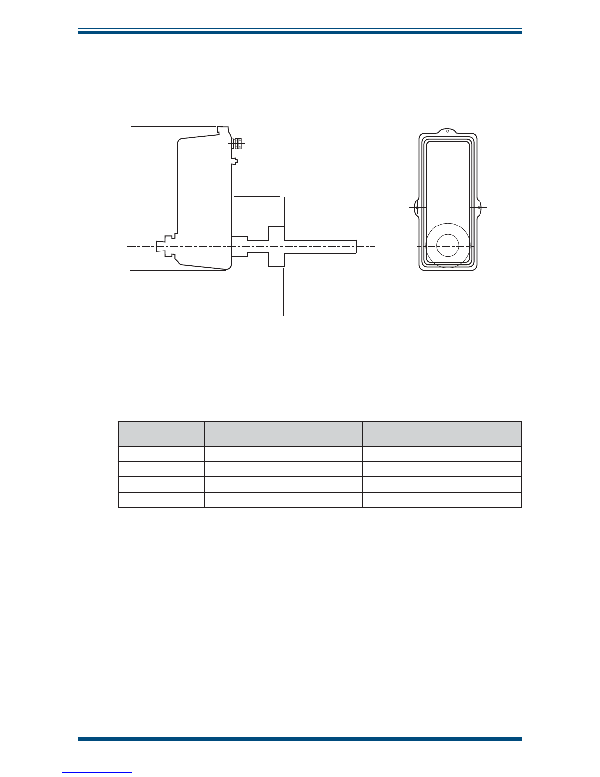
XZR500 User’s Manual
50 97137 Issue 8, April 2017
APPENDIX D
Appendix D XZR500 Sensor Head and Probe General Dimensions
290mm (11.41”)
97mm (3.82”)
260mm (10.24”)
X
290mm (11.41”)
133mm (5.24”)
S
S
S
S
S
S
S
S
S
S
S
S
X = 400, 600 or 900mm
Figure 19
XZR500 Sensor Head & Probe General Dimensions
Probe Version
Outer Tube Dimensions
Outer Diameter x Wall Thickness
Inner Tube Dimensions
Outer Diameter x Wall Thickness
Stainless Steel 33.4 x 3.37mm (1.31 x 0.13”) 13.7 x 1.65mm (0.54 x 0.06”)
Inconel 33.4 x 2.77mm (1.31 x 0.11”) 13.7 x 2.24mm (0.54 x 0.08”)
HR160 & C2000 33.4 x 3.38mm (1.31 x 0.13”) 13.7 x 1.65mm (0.54 x 0.06”)
Ceramic 30 x 2.5mm (1.18 x 0.09”) 14 x 5mm (0.55 x 0.19”)
Page 59

XZR500 User’s Manual
Michell Instruments 51
APPENDIX E
Appendix E
Back Flushing System
(Optional)
Page 60
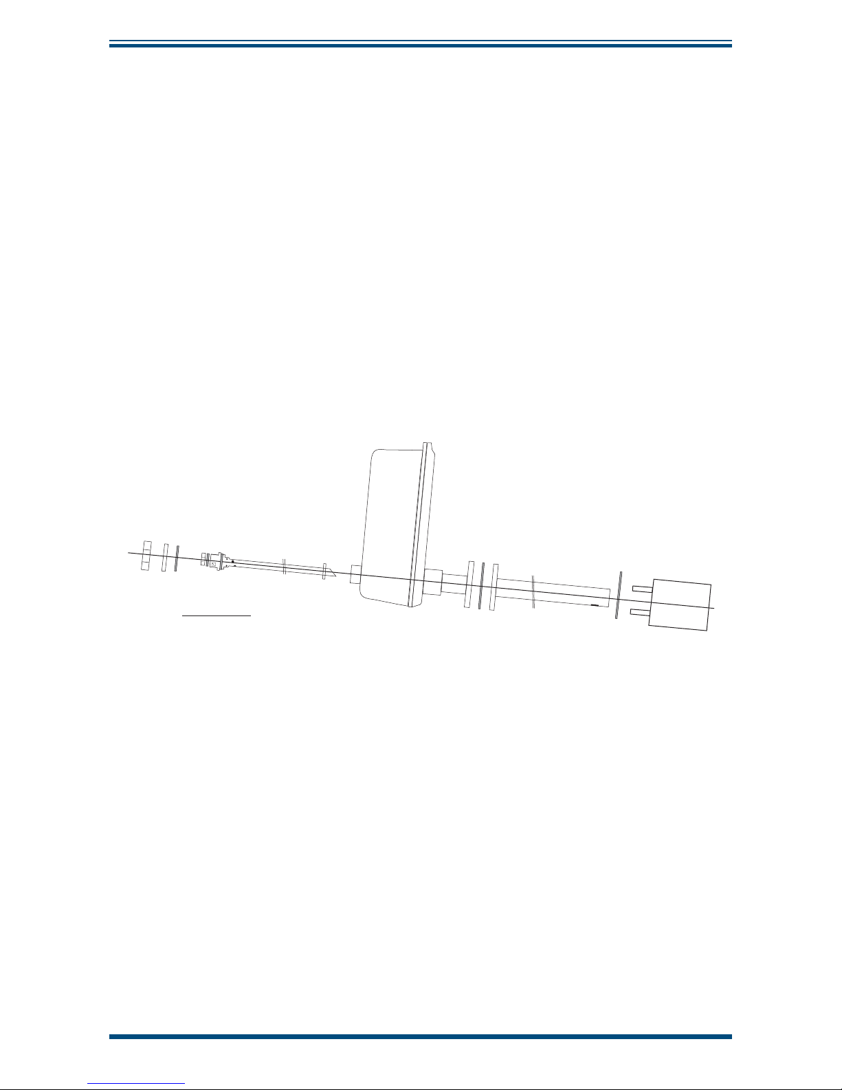
XZR500 User’s Manual
52 97137 Issue 8, April 2017
APPENDIX E
Appendix E Back Flushing System (optional)
The pressurized probe cleaning system comprises:
• A steel housing containing electronics and a connector block.
• A CD Rom for programming the automaton.
• An electro-valve with a connection to place on the back of the probe,
in place of the sealing screw, a cable (standard length = 6 meters) for
connecting the electro-valve.
• A hose for compressed air (standard length = 6 meters).
For positioning the probe tubes, see the drawing below:
f. Inner probe tube
3 marks to indicate
the bevelled edge
Horizontal line
Bevelled edge
e. Probe head
d. Gasket for flange
c. Outer tube
b. Gasket for flange
a. Tubular
counter flange
Gas Inlet hole
}
}
}
5°
}
}
}
}
}
}
}
h. Locking ring
i. Rear nut
g. Gasket for locking ring
}
}
}
}
}
Gasket
Nut
}
}
j. Gasket
Figure 20
Position of the Probe
Page 61
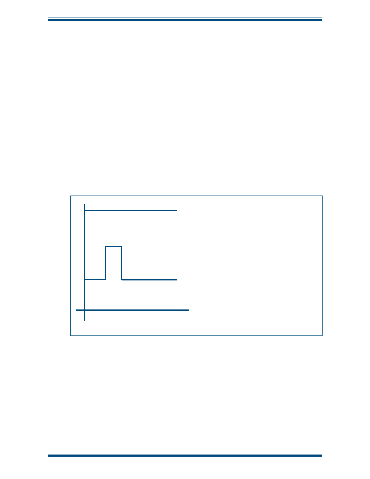
XZR500 User’s Manual
Michell Instruments 53
APPENDIX E
The output signal is frozen when the fl ushing sequence starts, it is free after t3.
The electro-valve opens after t1 during t2. Factory settings are:
• t1 = 2 seconds
• t2 = 3 seconds
• t3 = 20 seconds
Apply pressure (5-6 bars) during a short time (t2). The operator will decide the
frequency of cleaning, once every hour to once a month, according to the conditions of
use (factory setting = see the notice of the automaton).
NOTE: t2 should be short. Instead of leaving the electro-valve open for a
longer time, it is better to increase the frequency of cleaning.
If the electro-valve stays open too long, the fl ow of cold air would cool the
inside of the probe and this might encourage corrosion.
>
t1
t2
t3
t0
t0 beginning of the cycle, 4-20mA freezing
t1 time between the beginning of the cycle
and the valve opening
t2 duration for which valve is open
t3 duration of 4-20 mA freezing
Make the connections as follows:
• terminals 1 & 2: 230V-50Hz mains power supply
• terminals 3 & 4: wiring of electro-valve
• terminals 5 & 6: to connect with terminals 37 and 38 in the Control Unit
To modify the monitoring sequence of the fl ushing system, please refer to the manual
supplied with the automaton.
Page 62

XZR500 User’s Manual
54 97137 Issue 8, April 2017
APPENDIX F
Appendix F
Heated Flue Gas
Ejection System (Optional)
Page 63
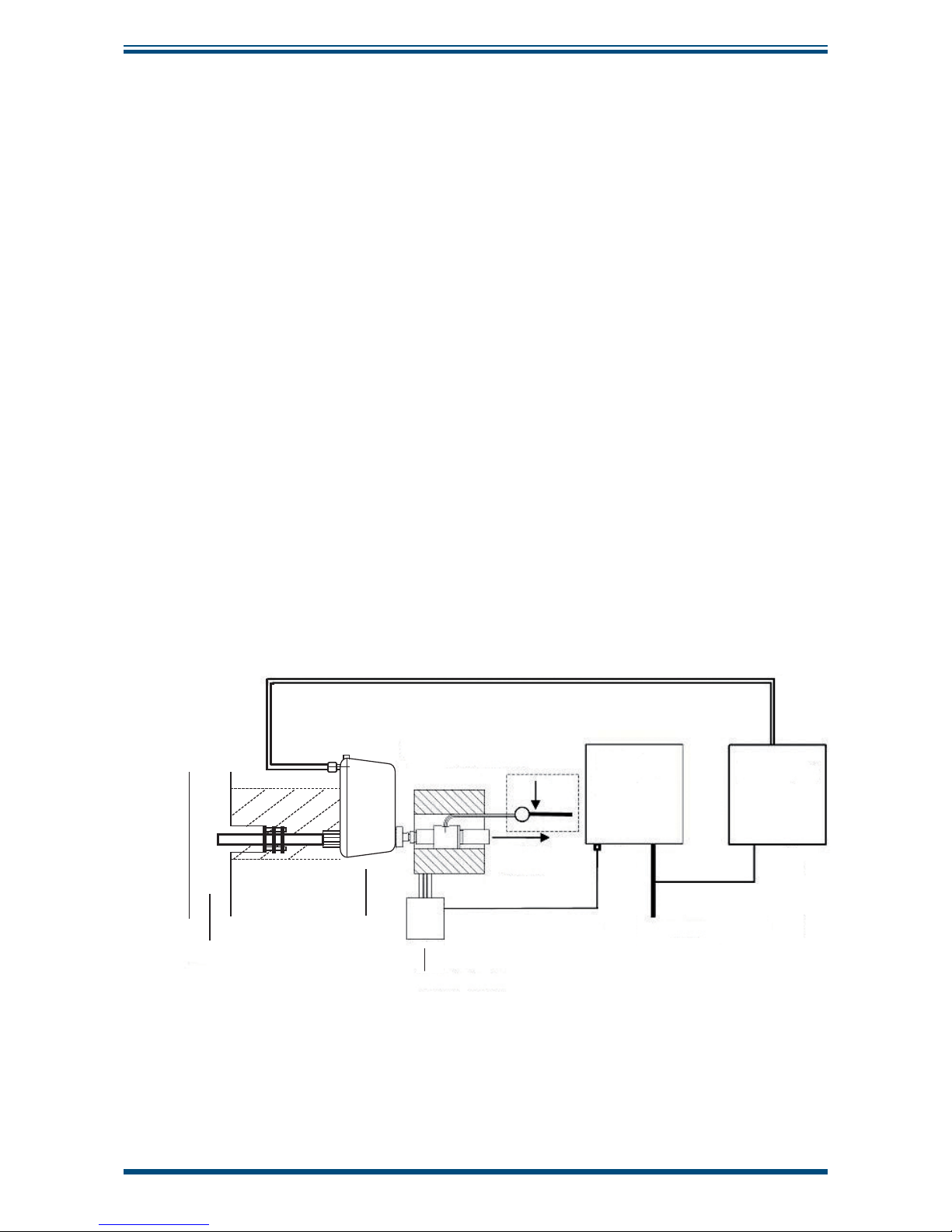
XZR500 User’s Manual
Michell Instruments 55
APPENDIX F
Appendix F Heated Flue Gas Ejection System (Optional)
The optional fl ue gas ejection system with heating is suitable for particularly severe
conditions of measurement. i.e. high stack gas temperature and high dust content.
In these cases a version without the inner probe tube can be used. A compressed air
ejection system draws the fl ue gases through the probe tube and heating minimizes
probe clogging. The system must be supplied with dry and de-oiled compressed air at
a pressure that can be adjusted between 0 and 3 relative bars.
The synoptic diagram of the installation follows. The system comprises:
• An XZR500 Sensor Head, without inner probe tube
• An air-ejector with adjustable fl ow placed at the sensor rear side. It is
heated and insulated
• An enclosure for controlling the ejector heating
• An intermediate junction box in case there is a large distance between
the probe and the regulation enclosure
• A compressed air connecting system
• Michell Instruments does not supply the system for cleaning the
compressed air and regulating the inlet pressure: the pressure regulator
should supply pressure between 0 and 3 bar.
Flue gas
exhaust
Heating
regulation
enclosure
Supply of compressed air
(CAUTION - PRESSURE
REGULATOR REQUIRED)
Heated ejector
230 VAC Supply
STACK
Sensor
Head
i
i
i
Control
Unit
Figure 21
Installation of the Ejector/Heating System
Page 64
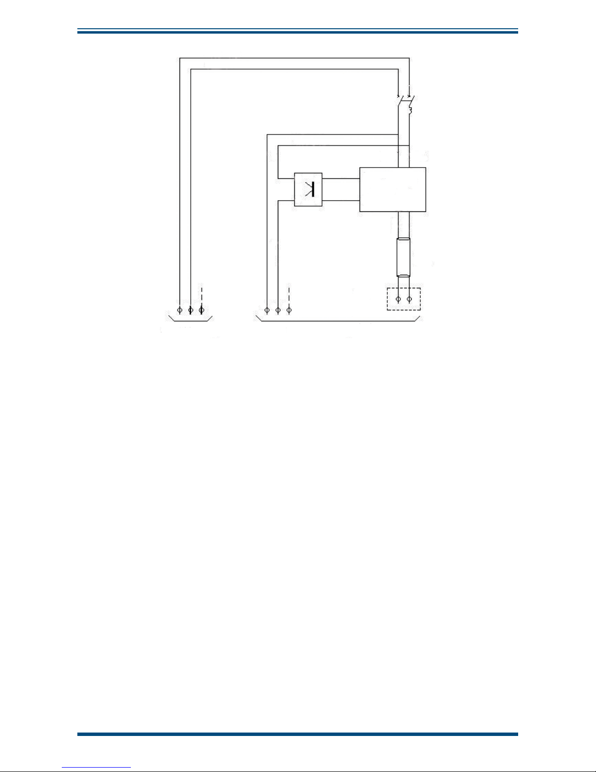
XZR500 User’s Manual
56 97137 Issue 8, April 2017
APPENDIX F
1.5mm2 Brown
1.5mm
2
Brown
1.5mm
2
Brown
1.5mm
2
Brown
1.5mm
2
Blue
1.5mm
2
Blue
1.5mm2
Blue
1
1
1
2
2
2
L1 3+
T1 4
-
3
3
4
4
5
5
5
Regulator
CB100
11 12
F1
6A
Green
White
Compensated cable
TC-K
Connector
TC-K
6
6
230V/6A Supply
To the heating insulator
Figure 22
Enclosure for Controlling the Ejector Heating - General Wiring Diagram
Confi guring the CB100 temperature regulator:
• Verify the display when powering up the regulator.
• To adjust the set point at 200°C, press the SET key and scroll with the
scroll keys.
• Cancellation of the alarms:
- Press the “SET” key during 2 seconds
- Get to “LCY”, enter code “1000”
- Press the “SET” key during 2 seconds
- Press the “SET” and R/S” keys: at “CODE”, enter code “0000”
- Get to S L 4, enter code “0000”
- Get to S L 5, enter code “0000”
• Adjustment of high threshold, still in the confi guration menu:
- Validate with the “SET” key up to “CODE”, enter code “1”
- Press the “SET” key
- At “SLH”, set the high-temperature maxi=203°C (using the scroll
keys and the “SET” key)
- At “SLL”, set the low-temperature (mini 150°C)
- Validate with the “SET” key up to “CODE”, enter code “0” and set
back S L 4
and S L 5 at 1
- To exit press “SET” and “R/S” keys
Page 65

XZR500 User’s Manual
Michell Instruments 57
APPENDIX F
Specifi c preventive maintenance for the optional heated ejector:
Because of the high rate of dust present in this kind of application, regular preventive
maintenance is essential.
Because blocking is likely to occur in the heated ejector it should be cleaned out regularly
to prevent it from getting completely clogged up. A small stick (like a welding stick) or
a metal swab should be used if the dust is minimal. In the case of the ejector being
completely clogged up it should be washed with hot water.
We advise that you have a complete ejector (ref. 205 021) as a spare.
In order to optimize the installation and reduce the risk of clogging, mount the probe
on a small fl ange. We recommend Michell Instruments’ optional counter-fl ange - see
Appendix G). Provide proper insulation for both the fl ange and the ejector.
Application and wiring examples:
Control Unit (201030)
400 x 600 P200 Polyester enclosure
Cable (104003)
TC-K Compensated cable (104059)
2 x 1.5mm² PRFE shielded cable (104069)
230V Supply
4-20mA Output
d
d
d
d
d
Page 66

XZR500 User’s Manual
58 97137 Issue 8, April 2017
APPENDIX G
Appendix G
Mounting Options
Page 67

XZR500 User’s Manual
Michell Instruments 59
APPENDIX G
Appendix G Mounting Options
G.1 Tubular Counter Flange and Insulators
Up
100mm (3.93”)
37mm (1.45”)
55mm (2.16”)
80mm (3.14”)
70mm (2.75”)
40mm (1.57”)
M8 SS STUD
(x4 at 90
o
)
h
h
g
g
g
g
g
g
g
gh
h
h
h
Figure 23
XZR500 Flange and Back Flange (Optional)
g
g
h
h
h
h
h
h
h
h
h
h
h
h
h
h
g
g
g
g
A.A.
175mm
Ø185mm
Ø85±2
A
MADE OF TWO HALF-SHELLS ALUMINUM PROTECTIVE COVER (ISOXAL 8/10)
CLOSED INSULATOR
GLASS WOOL (PS1713 ISOVER)
Aluminum protective cover (ISOXAL 8/10)
A.A.
80
40
Glass wool PS1713 (ISOVER)
A
A
A
110mm
110mm
30
50
30
30
50
30
h
h
h
h
h
h
h
h
Figure 24
Insulators (Flange and Rear Sealing Screw)
Page 68

XZR500 User’s Manual
60 97137 Issue 8, April 2017
APPENDIX G
G.2 Mounting Plate Dimensions
45° 45°
M8
(x4 at 90°)
ø55
ø40
100cm (39.3”)
100cm (39.3”)
4cm (1.6”) 30cm (11.8”)
Figure 25
Mounting Plate Dimensions
Page 69

XZR500 User’s Manual
Michell Instruments 61
APPENDIX H
Appendix H
Second 4-20mA Output
Page 70
XZR500 User’s Manual
62 97137 Issue 8, April 2017
APPENDIX H
Appendix H Second 4-20 mA Output
The optional 2nd analog output allows acquisition of a linear 4-20 mA current
corresponding to the 0.1% - 25% scale (this scale cannot be changed).
This 4-20 mA output is galvanic isolated (500 V).
Wiring of the 2nd 4-20 mA output on the connector (on the electronic card) is as follows:
• terminal 27 = “-” 4-20 mA
• terminal 28 = “+” 4-20 mA
h
- +
27 28
Connector Connector
29
38
39
50
Electronic Card
2nd 4-20 mA Output Connector
For the connection use
shielded cable 2 x 0.75mm².
Bare 8mm of the wire end on
the terminal’s side and
connect the braid to the
copper bar near the cable
gland.
Figure 26
Wiring of the Second 4-20 mA Output
Page 71

XZR500 User’s Manual
Michell Instruments 63
APPENDIX I
Appendix I
Automatic Calibration
(Optional)
Page 72

XZR500 User’s Manual
64 97137 Issue 8, April 2017
APPENDIX I
Appendix I Automatic Calibration (Optional)
The analyzer can be automatically calibrated, if this function has been purchased, and
can be as simple as pressing a button to start up the sequence. This assumes that the
calibration gas is connected permanently and the cal gas value is properly confi gured
in the electronics.
The sequence can be initiated by either using the keys at on the control unit or via your
computer with RS232 interface (refer to Appendix B).
The calibration sequence lasts 5 minutes.
The output signal is frozen at its last value before setting the sequence and is unfrozen
at the end of the purging sequence.
Page 73

XZR500 User’s Manual
Michell Instruments 65
APPENDIX J
Appendix J
Quality, Recycling
& Warranty
Information
Page 74

XZR500 User’s Manual
66 97137 Issue 8, April 2017
APPENDIX J
Appendix J Quality, Recycling & Warranty Information
Michell Instruments is dedicated to complying to all relevant legislation and directives.
Full information can be found on our website at:
www.michell.com/compliance
This page contains information on the following directives:
• ATEX Directive
• Calibration Facilities
• Confl ict Minerals
• FCC Statement
• Manufacturing Quality
• Modern Slavery Statement
• Pressure Equipment Directive
• REACH
• RoHS2
• WEEE2
• Recycling Policy
• Warranty and Returns
This information is also available in PDF format.
Page 75

XZR500 User’s Manual
Michell Instruments 67
APPENDIX K
Appendix K
Return Document &
Decontamination Declaration
Page 76

XZR500 User’s Manual
68 97137 Issue 8, April 2017
APPENDIX K
Appendix K Return Document & Decontamination Declaration
F0121, Issue 2, December 2011
'HFRQWDPLQDWLRQ&HUWL¿FDWH
IMPORTANT NOTE: Please complete this form prior to this instrument, or any components, leaving your
site and being returned to us, or, where applicable, prior to any work being carried out by a Michell
engineer at your site.
Instrument Serial Number
Warranty Repair? YES NO Original PO #
Company Name Contact Name
Address
Telephone # E-mail address
Reason for Return /Description of Fault:
Has this equipment been exposed (internally or externally) to any of the following?
Please circle (YES/NO) as applicable and provide details below
Biohazards YES NO
Biological agents YES NO
Hazardous chemicals YES NO
Radioactive substances YES NO
Other hazards YES NO
Please provide details of any hazardous materials used with this equipment as indicated above (use continuation sheet
if necessary)
Your method of cleaning/decontamination
Has the equipment been cleaned and decontaminated? YES NOT NECESSARY
Michell Instruments will not accept instruments that have been exposed to toxins, radio-activity or bio-hazardous
PDWHULDOV)RUPRVWDSSOLFDWLRQV LQYROYLQJVROYHQWVDFLGLFEDVLFÀDPPDEOHRU WR[LFJDVHV DVLPSOH SXUJHZLWKGU\
JDVGHZSRLQW&RYHUKRXUVVKRXOGEHVXI¿FLHQWWRGHFRQWDPLQDWHWKHXQLWSULRUWRUHWXUQ
Work will not be carried out on any unit that does not have a completed decontamination declaration.
Decontamination Declaration
I declare that the information above is true and complete to the best of my knowledge, and it is safe for Michell
personnel to service or repair the returned instrument.
Name (Print) Position
Signature Date
Page 77

Page 78

http://www.michell.com
 Loading...