


MDM300 I.S.
Advanced Dew-Point Hygrometer
User’s Manual


 -I.S.
-I.S.


97213 Issue 5
October 2017

Please fill out the form(s) below for each instrument that has been purchased.
Use this information when contacting Michell Instruments for service purposes.
Hygrometer
Code
Serial Number
Invoice Date
Location of Instrument
Tag No
Hygrometer
Code
Serial Number
Invoice Date
Location of Instrument
Tag No
Hygrometer
Code
Serial Number
Invoice Date
Location of Instrument
Tag No


 -I.S.
-I.S.


MDM300 I.S.
Advanced Dew-Point Hygrometer (for use in hazardous areas)
For Michell Instruments' contact information please go to www.michell.com
© 2017 Michell Instruments
This document is the property of Michell Instruments Ltd. and may not be copied or otherwise reproduced, communicated in any way to third parties, nor stored in any Data Processing System without the express written authorization of Michell Instruments Ltd.
|
|
|
MDM300 I.S. User’s Manual |
|
|
||
|
|
||
Contents |
|
||
Safety ............................................................................................................................... |
|
vii |
|
|
Electrical Safety ......................................................................................................... |
vii |
|
|
Pressure Safety........................................................................................................... |
vii |
|
|
Toxic Materials ............................................................................................................ |
vii |
|
|
Repair and Maintenance .............................................................................................. |
vii |
|
|
Calibration.................................................................................................................. |
vii |
|
|
Safety Conformity ....................................................................................................... |
vii |
|
Abbreviations |
viii |
||
Warnings .......................................................................................................................... |
|
viii |
|
1 |
INTRODUCTION ................................................................................................ |
1 |
|
|
1.1 |
Controls .......................................................................................and Indicators |
3 |
|
1.2 |
Function .....................................................................................................Keys |
5 |
|
1.2.1 |
..................................................................................................... |
5 |
|
1.2.2 |
........................................................................... |
5 |
|
1.2.3 |
............................................................................................... |
5 |
|
1.2.4 |
.................................................................................... |
5 |
|
1.3 |
Instrument .............................................................................................Display |
6 |
|
1.3.1 |
................................................................................................. |
7 |
|
1.3.2 |
.............................................................................. |
8 |
2 |
INSTALLATION .................................................................................................. |
9 |
|
|
2.1 |
Safety................................................................................................................ |
9 |
|
2.2 |
Unpacking ...................................................................................the Instrument |
9 |
|
2.3 |
MDM300 ..................................................................................I.S. Accessories |
10 |
|
2.4 |
Operational .................................................................................Requirements |
12 |
|
2.4.1 |
................................ |
12 |
|
2.4.2 |
................................................................... |
12 |
|
2.5 |
Instrument .............................................................................Gas Connections |
12 |
|
2.5.1 |
............................................................................. |
13 |
|
2.6 |
Connect ..................................................................................External Sensors |
14 |
|
2.6.1 |
.................................................................. |
15 |
|
2.6.2 |
................................................................................ |
15 |
|
2.7 |
Battery ..............................................................................................Charging |
16 |
3 |
OPERATION .................................................................................................... |
18 |
|
|
3.1 |
Preparation ..................................................................................for Operation |
18 |
|
3.2 |
Instrument ........................................................................................Start-Up |
19 |
|
3.3 |
Overall ................................................................Menu Structure and Operation |
20 |
|
3.3.1 |
.............................................................................................. |
20 |
|
3.3.2 |
................................................................................................. |
20 |
|
3.4 |
SET ..................................................................................-UP Menu Parameters |
22 |
|
3.4.1 |
.................................................................................................. |
22 |
|
3.4.2 |
................................................................................................... |
23 |
|
3.4.3 |
............................................................................................... |
24 |
|
3.4.3.1 ................................................................... |
25 |
|
|
3.4.4 |
..................................................................... |
26 |
|
3.4.5 |
....................................................................................................... |
27 |
|
3.4.6 |
........................................................................................................... |
28 |
|
3.4.7 |
.......................................................................................................... |
29 |
|
3.4.8 |
............................................................................................... |
29 |
|
3.4.9 |
.......................................................................................... |
30 |
|
3.4.10 |
................................................................................................. |
30 |
|
3.4.11 |
............................................................................................. |
31 |
|
3.5 |
Default ...........................................................................................Parameters |
32 |
iv |
97213 Issue 5, October 2017 |

MDM300 I.S. User’s Manual
|
3.6 |
Guide to Measurement and Sampling................................................................. |
33 |
|
3.6.1 |
Measuring at Atmospheric or System Pressure .............................................. |
34 |
|
3.6.2 |
Measurement Guide .................................................................................... |
35 |
|
3.6.3 |
Conditional Sensor Purge............................................................................. |
37 |
|
3.7 |
Battery Management ........................................................................................ |
37 |
|
3.7.1 |
Battery Troubleshooting............................................................................... |
37 |
4 |
GOOD MEASUREMENT PRACTICE ..................................................................... |
38 |
|
|
4.1 |
Sampling Hints ................................................................................................. |
39 |
5 |
APPLICATION SOFTWARE ................................................................................ |
42 |
|
6 |
CALIBRATION.................................................................................................. |
43 |
|
|
6.1 |
Traceability ...................................................................................................... |
43 |
|
6.2 |
Calibration Method ........................................................................................... |
44 |
|
6.3 |
Calibration Correction Method ........................................................................... |
45 |
7 |
SHIPPING ....................................................................................................... |
46 |
|
Appendices
Appendix A |
Technical Specifications.............................................................................. |
48 |
|
|
A.1 |
Dimensions ................................................................................. |
49 |
Appendix B |
Datalog Status Display ............................................................................... |
51 |
|
Appendix C |
Hazardous Area Certification ...................................................................... |
54 |
|
|
C.1 |
Product Standards ....................................................................... |
54 |
|
C.2 |
Product Certification .................................................................... |
54 |
|
C.3 |
Global Certificates/Approvals ........................................................ |
54 |
|
C.4 |
Input Terminal Parameters .......................................................... |
54 |
|
C.5 |
Special Conditions of Use ............................................................. |
55 |
|
C.6 |
Maintenance and Installation........................................................ |
55 |
Appendix D |
FCC Declaration......................................................................................... |
57 |
|
Appendix E |
Quality, Recycling & Warranty Information................................................... |
59 |
|
Appendix F |
Return Document & Decontamination Declaration........................................ |
61 |
|
Michell Instruments |
v |

|
|
MDM300 I.S. User’s Manual |
|
Figures |
|
|
|
Figure 1 |
MDM300 I.S. Advanced Dew-Point Hygrometer............................................. |
2 |
|
Figure 2 |
User Connections, Controls and Indicators.................................................... |
3 |
|
Figure 3 |
Instrument Display ..................................................................................... |
|
6 |
Figure 4 |
Packing Method.......................................................................................... |
|
9 |
Figure 5 |
Gas Port Adaptors .................................................................................... |
|
10 |
Figure 6 |
Accessories .............................................................................................. |
|
11 |
Figure 7 |
Bonded Seal Fitting .................................................................................. |
|
13 |
Figure 8 |
Gas Coupling Examples for Atmospheric Pressure Measurement................... |
13 |
|
Figure 9 |
MDM300 I.S. Remote Sensor Interface....................................................... |
14 |
|
Figure 10 |
External Sensor Connection....................................................................... |
|
14 |
Figure 11 |
Typical External Dew-Point Display............................................................. |
15 |
|
Figure 12 |
Battery Charger Connection ...................................................................... |
|
16 |
Figure 13 |
Start-Up Sequence ................................................................................... |
|
19 |
Figure 14 |
Menu Structure ........................................................................................ |
|
21 |
Figure 15 |
SETTINGS Page........................................................................................ |
|
22 |
Figure 16 |
LOGGING Page......................................................................................... |
|
23 |
Figure 17 |
BLUETOOTH Page .................................................................................... |
|
24 |
Figure 18 |
Typical Bluetooth Pairing Sequence............................................................ |
25 |
|
Figure 19 |
EXTERNAL SET-UP Page............................................................................ |
|
26 |
Figure 20 |
CLOCK Page............................................................................................. |
|
27 |
Figure 21 |
HMI Page................................................................................................. |
|
28 |
Figure 22 |
INFO Page ............................................................................................... |
|
29 |
Figure 23 |
CHART Page............................................................................................. |
|
29 |
Figure 24 |
LOG FILES Page ....................................................................................... |
|
30 |
Figure 25 |
LOGS Page............................................................................................... |
|
30 |
Figure 26 |
CALIBRATION Page .................................................................................. |
|
31 |
Figure 27 |
Easi-Fit Sample Kit |
MDM300 Panel-Mount Sampling System ......... |
33 |
Figure 28 |
Large and Small Orifice Fitting................................................................... |
34 |
|
Figure 29 |
Typical Application Software Screen ........................................................... |
42 |
|
Figure 30 |
Typical 7-point Calibration Certificate ......................................................... |
43 |
|
Figure 31 |
Calibration Menu Page .............................................................................. |
|
45 |
Figure 34 |
Instrument Packing Details........................................................................ |
|
46 |
Figure 35 |
Dimensions - MDM300 I.S. ........................................................................ |
|
49 |
Figure 36 |
Current Datalog File Display ...................................................................... |
|
51 |
Figure 37 |
MDM300 I.S. Status Register..................................................................... |
|
51 |
Figure 38 |
MDM300 I.S. Status Register (Hex 28) ....................................................... |
51 |
|
Tables |
|
|
Table 1 |
Controls and Indicators................................................................................ |
4 |
Table 2 |
Instrument Display Descriptions ................................................................... |
6 |
Table 3 |
Adaptor Fittings......................................................................................... |
12 |
Table 4 |
SETTINGS Parameters ............................................................................... |
22 |
Table 5 |
LOGGING Parameters ................................................................................ |
23 |
Table 6 |
BLUETOOTH Parameters ............................................................................ |
24 |
Table 7 |
EXTERNAL Sensor Parameters .................................................................... |
26 |
Table 8 |
CLOCK Parameters .................................................................................... |
27 |
Table 9 |
HMI Parameters ........................................................................................ |
28 |
Table 10 |
MDM300 I.S. Default Parameters ................................................................ |
32 |
Table 11 |
MDM300 I.S. Measurement Procedures ....................................................... |
35 |
Table 12 |
Example Of Calibration Run Readings.......................................................... |
44 |
Table 13 |
Status Register Flags ................................................................................. |
52 |
vi |
97213 Issue 5, October 2017 |
MDM300 I.S. User’s Manual
Safety
The manufacturer has designed this equipment to be safe when operated using the procedures detailed in this manual. The user must not use this equipment for any other purpose than that stated. Do not apply values greater than the maximum value stated.
This manual contains operating and safety instructions, which must be followed to ensure the safe operation and to maintain the equipment in a safe condition. The safety instructions are either warnings or cautions issued to protect the user and the equipment from injury or damage. Use competent personnel using good engineering practice for all procedures in this manual.
Electrical Safety |
! |
The instrument is designed to be completely safe when used with options and accessories supplied by the manufacturer for use with the instrument. The instrument is powered by an internally mounted rechargeable battery - this battery should never be allowed to fully discharge. The input power supply voltage limits for the battery charger supplied with the instrument are 100 to 240 V AC, 50/60 Hz.
NOTE: No other battery charger unit, other than that supplied with the instrument should be used.
NOTE: Do not allow the battery to fully discharge.
Pressure Safety |
! |
DO NOT permit pressures greater than the safe working pressure to be applied to the instrument. The specified safe working pressure (SWP), for this instrument is 350 barg (5076 psig).
Toxic Materials |
! |
The use of hazardous materials in the construction of this instrument has been minimized. During normal operation it is not possible for the user to come into contact with any hazardous substance which might be employed in the construction of the instrument. Care should, however, be exercised during maintenance and the disposal of certain parts.
Repair and Maintenance
The instrument must be maintained either by the manufacturer or an accredited service agent. Refer to www.michell.com for details of Michell Instruments’ worldwide offices contact information.
Calibration
The recommended calibration interval for the MDM300 I.S. is 12 months. The instrument should be returned to the manufacturer, Michell Instruments Ltd., or one of their accredited service agents for re-calibration.
Safety Conformity
This product meets the essential protection requirements of the relevant EU directives. Further details of applied standards may be found in Appendix F.
Michell Instruments |
vii |

MDM300 I.S. User’s Manual
Abbreviations
The following abbreviations are used in this manual:
AC |
alternating current |
atm |
pressure unit (atmosphere) |
barg |
pressure unit (=100 kP or 0.987 atm) gauge |
bara |
bar absolute |
°C |
degrees Celsius |
°F |
degrees Fahrenheit |
K |
Kelvin (absolute temperature) |
COM |
common |
DC |
direct current |
ft |
foot (feet) |
Hz |
Hertz |
kg |
kilogram(s) |
lb |
pound |
Nl/min |
liters per minute |
m |
meter(s) |
mA |
milliampere |
Mb |
megabytes |
max |
maximum |
min |
minute(s) |
mm |
millimeter(s) |
MPa |
megapascal |
No. |
number |
PIN |
personal identification number |
ppmV |
parts per million (by volume) |
ppmW |
parts per million (by weight) |
psig |
pounds per square inch |
scfh |
standard cubic feet per hour |
SWP |
safe working pressure |
sec |
second(s) |
V |
volts |
Warnings
The following general warning listed below is applicable to this instrument. It is repeated in the text in the appropriate locations.
Where this hazard warning symbol appears in the following sections it is used to indicate areas where potentially hazardous operations need to be carried out.
viii |
97213 Issue 5, October 2017 |
MDM300 I.S. User’s Manual |
INTRODUCTION |
|
|
|
|
1 INTRODUCTION
The MDM300 I.S. Advanced Dew-Point Hygrometer is a portable instrument designed for online measurement of moisture content in non-corrosive gases in hazardous areas, over an operational range of -100 to +20°C (-148 to +68°F).
The instrument is independently assessed and certificated as being intrinsically safe and fully compatible with safe operation within defined Zone 0 hazardous areas.
The instrument is contained within a steel fiber-loaded high-impact polyamide 6 case, sealed to IP66 / NEMA4 standard and is powered by an internally mounted Nickel Metal Hydride (NiMH) battery, designed to typically provide 24 hours continuous use between charges. Continuous battery charge status indication is provided. Additional battery status information is provided by a battery indicator icon, in addition to a warning beep and Shutdown Mode.
The MDM300 I.S. is fitted with an internally mounted ceramic sensor, which is enhanced for a quicker response to dew points as dry as -75°Cdp (-103°Fdp).
The MDM300 I.S. can also be used to read the dew-point signal from a Michell Instruments’ Easidew I.S. transmitter. To do this, the MDM300 I.S. Remote Sensor Interface is used to connect to the Easidew I.S. transmitter.
No other sensor can be connected to the MDM300 I.S.
A graphical display presents the dew-point data in large format characters and simultaneously provides a primary display of real time dew-point readings and a secondary display, in smaller characters, for the external sensor input. If no external input is programmed, gas temperature (measured by the internal sensor) is displayed by default.
A fully programmable, real-time, datalogging facility is provided which has an internal memory capacity of 8Mb, capable of storing up to 10,000 logs per file (typically giving a maximum of 64 log files).
A Bluetooth, wireless, communication system is provided, giving access to a dedicated, PC based, MDM300 I.S. Software Application Package which provides the facility for handling the logged data files and uploading and downloading instrument parameters.
A user-friendly operator interface provides easy access to all levels of the instrument’s functionality.
An easy-to-follow calibration routine is built into the instrument’s software.
Michell Instruments |
1 |
INTRODUCTION |
MDM300 I.S. User’s Manual |
|
|
|
|
Two versions of the instrument are available, an MDM300 (standard) version and an MDM300 I.S. (intrinsically safe) version.
This manual covers the MDM300 I.S. version only.
For information about the MDM300 contact your local Michell Instruments’ representative (contact information at www.michell.com).


 -I.S.
-I.S.


Figure 1 MDM300 I.S. Advanced Dew-Point Hygrometer
(for use in hazardous areas)
2 |
97213 Issue 5, October 2017 |
MDM300 I.S. User’s Manual |
INTRODUCTION |
|
|
|
|
1.1Controls and Indicators
The controls and indicators associated with the MDM300 I.S. instrument are located on the front panel of the instrument.
Connections to the MDM300 I.S. dew-point hygrometer, comprising the gas ports, battery charger input connector and input connector for the external sensor are all made to the top panel.
Figure 2 shows the layout of these controls and Table 1 describes their respective operational functions.
2


 - I.S.
1
.S.I- 

7 |
6 |
5 |
4 |
3 |
Figure 2 User Connections, Controls and Indicators
Michell Instruments |
3 |

INTRODUCTION |
|
|
MDM300 I.S. User’s Manual |
|
|
|
|
|
|
|
|
|
|
|
|
|
|
|
|
|
Item |
Panel |
Description |
|
|
|
|
|
|
|
1 |
Front |
Function keys. Refer to Section 1.2 for the details of these |
|
|
keys. |
|
||
|
|
|
|
|
|
|
|
|
|
|
|
|
Instrument display, partitioned to show 3 main panels: |
|
|
|
|
The primary display shows internal sensor parameters. |
|
|
2 |
Front |
The |
secondary display indicates the external sensor |
|
parameter. |
|||
|
|
|
||
|
|
|
The status display area shows icons representing battery |
|
|
|
|
charge state, initialization in progress, data logging in |
|
|
|
|
progress, keyboard lock status and keyboard beep status. |
|
|
|
|
|
|
|
|
|
Instrument ON/OFF switch. |
|
|
3 |
Top |
NOTE: The instrument does not need be switched ON |
|
|
|
|
in order to charge the internal NiMH battery. |
|
|
|
|
|
|
|
4 |
Top |
Gas Output port. Refer to Section 2.5. |
|
|
|
|
|
|
|
5 |
Top |
Gas Input port. Refer to Section 2.5. |
|
|
|
|
|
|
|
|
|
Analog input connector for external sensor. |
|
|
|
|
By default, this signal is displayed in the secondary display |
|
|
|
|
area but may be configured to be displayed as the primary |
|
|
|
|
display. |
|
|
6 |
Top |
If no external input is selected, the internal sensor |
|
|
|
|
||
|
|
|
temperature is shown, on the secondary display, by default |
|
|
|
|
(refer to Section 3.4.6). |
|
|
|
|
NOTE: The hinged rubber protection cover should be |
|
|
|
|
kept closed when the connector is not in use. |
|
|
|
|
|
|
|
|
|
Socket for connection of battery charger (located behind |
|
|
|
|
secured cover). |
|
|
|
|
|
Connection to the battery charger should |
|
|
|
! |
always be made in a safe area - never in a |
|
7 |
Top |
|
hazardous area environment |
|
The secured cover should be kept screwed on when the |
|||
|
|
|
||
|
|
|
connector is not in use. |
|
|
|
|
! |
ONLY USE THE CHARGER PROVIDED |
|
|
|
! |
Never allow the battery to fully discharge |
|
|
|
|
|
Table 1 Controls and Indicators
4 |
97213 Issue 5, October 2017 |

MDM300 I.S. User’s Manual |
INTRODUCTION |
|
|
|
|
1.2Function Keys
The function keys, located on the front panel, are used to select operations from the menus and to select and enter parameter variables within those menu levels.
The function key described is shaded darker and the operation of the keys is as follows:
1.2.1Enter Key
The Enter key is used within the menus to highlight and select options and to accept entered values.
Operation of this key from the Main Display causes the Passcode entry page (for entry to the SET-UP Menu) to be displayed.
1.2.2Up () and Down () Keys
Within the SET-UP Menu and sub-menus these and keys are used to scroll down and highlight options.
Within sub-menu levels requiring the entry of alpha numeric values, these keys are used to change the values. Pressing the key once increases or decreases the selected field by one step. Pressing and holding the key will cause the selected field to be continuously increased or decreased until the key is released.
1.2.3Right () Key
Within sub-menu levels requiring the entry of alpha numeric values, this key is used to shift the insertion point right in the file name entry field.
From the Main Display, pressing this key moves to the Chart
Page.
From the Chart Page, pressing this key moves to the Logging
Pages.
1.2.4Left () / Escape Key
Within sub-menu levels requiring the entry of alpha numeric values, this key is used to shift the insertion point left in the file name entry field. As the insertion point is shifted to the left, the entry at the former position is deleted.
Within any menu or sub-menu level, pressing this key escapes to the previous menu above the current level.
Michell Instruments |
5 |
INTRODUCTION |
MDM300 I.S. User’s Manual |
|
|
|
|
1.3Instrument Display
The graphics display and the associated function keypad (Figure 2), form the operator interface of the equipment. Figure 3 shows all the elements of a typical display page after the instrument’s initialization period has completed.
Table 2 details the elements of the display:
Dewpoint |
Internal |
6.9 |
°C |
12.7 |
|
°C Temp. |
Measurement in progress |
8 |
7 |
6 |
5 |
4 |
3 |
2 |
1 |
Figure 3 Instrument Display
Item Description
Secondary display
1Shows reading from external sensor, if configured; or internal temperature if external sensor is not configured (refer to Section 3.4.6).
Battery charge indicator icon
2Flashes when the battery needs charging. A warning beep sounds when the battery charge level is critical - followed immediately by Shutdown Mode.
NOTE: The icon becomes animated when the charger is connected.
3Keyboard beep indicator
Indicates that the keyboard beep is switched on.
4Keyboard lock indicator
Indicates that the keyboard is locked.
5Datalog status indicator
Indicates that logging is enabled and running.
Sensor initializing indicator
6Indicates that the initialization process is in progress and that the sensor heating is on. The presence of this symbol is accompanied by Initializing internal sensor status message.
Primary display
7During normal operation, the internal sensor readings are shown in the primary display. If the external sensor has been configured then this reading can be shown in this display (refer to Section 3.4.6).
8Status message display area
Displays status and error messages.
Table 2 Instrument Display Descriptions
6 |
97213 Issue 5, October 2017 |
MDM300 I.S. User’s Manual |
INTRODUCTION |
|
|
|
|
1.3.1Display Units
The instrument can display the measured reading in the following units:
Absolute Humidity
•lb/MMscf
•g/m3
•g/m3 NG
Moisture Content
•ppmV NG
•ppmV
•ppmW (AIR, USER, H2, SF6, CO2 or N2)
Dew Point
•°C
•°F
•K
Relative Humidity (%)
Mixing Ratio
•g/kg (AIR, USER, H2, SF6, CO2 or N2)
To toggle between displayed units, press either the or key.
Michell Instruments |
7 |
INTRODUCTION |
MDM300 I.S. User’s Manual |
|
|
|
|
1.3.2Status Display Indications
‘Initializing Internal Sensor’
This is displayed immediately after the instrument has been powered up, and indicates that the sensor is being heated up to accelerate equilibrium with the moisture in the sample gas. This has the effect of drying the sensor out, and results in the ‘undershoot’ seen in the first stage of the measurement process.
‘Measurement in Progress’
This is displayed after the sensor initialization has finished, and indicates that the sensor is running through the following initial measurement procedure:
1.Undershooting the dew-point
2.Making a first estimate
3.Running a QRA (Quick Response Algorithm), if necessary
Once the message has disappeared, this indicates that the instrument has finished its accelerated approach to the actual dew point. Depending on the conditions, it may continue to respond for a number of minutes more, before settling on (or tracking) the actual measured dew point.
Other Status Display Indications
Internal sensor |
|
Dew-point reading out of range (> +30 / < -120°C) |
|
error |
|
|
|
|
|
|
|
Internal thermistor |
Sensor internal temperature reading out of range (> +100 / |
||
< -40°C) or |
|||
error |
|
|
Thermistor fault |
|
|
|
|
|
|
|
|
External sensor |
|
External Sensor Input out of range (< 4 mA / > 20 mA) |
|
error |
|
|
|
|
|
|
|
Battery low |
|
Battery level low - recharge as soon as possible |
|
Battery |
low |
- |
Battery level critical - recharge immediately |
recharge now |
|
|
|
Log finished |
|
Log file has reached the maximum of 10,000 logs and logging has |
|
|
been stopped |
||
|
|
|
|
Internal sensor not |
Could not detect internal sensor on power up |
||
found |
|
|
|
Default CONFIG file |
Config. file missing, new file created and default settings used |
||
used |
|
|
|
8 |
97213 Issue 5, October 2017 |
MDM300 I.S. User’s Manual |
INSTALLATION |
|
|
|
|
2 INSTALLATION
2.1Safety
It is essential that the installation of the electrical and ! gas supplies to this instrument be undertaken by qualified
personnel.
2.2Unpacking the Instrument
The MDM300 I.S. instrument is packed into a standard box and the method of unpacking is shown below:
|
|
I |
. |
Hygrometer |
|
|
|
.S |
|
|
|
|
-PointManual |
|
|||
MDM300 |
|
|
|
|
|
|
Dew |
|
|
|
|
Advanced |
User’s |
|
|
4 |
|
|
|
|
|
||
|
|
|
|
|
|
3 |
|
|
|
|
|
- |
|
I |
|
. |
|
S |
. |
2 |
1 |
Figure 4 Packing Method
1.Open the box (1) and unpack carefully.
2.Remove the MDM300 I.S. (2), the user’s manual (3) and the accessories box (4).
3.Save all the packing materials for the purpose of returning the instrument for re-calibration or any warranty claims.
4.If the optional carry bag has been ordered it will be located underneath the foam insert, in a cardboard box.
Michell Instruments |
9 |
INSTALLATION |
MDM300 I.S. User’s Manual |
|
|
|
|
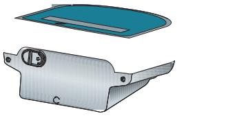
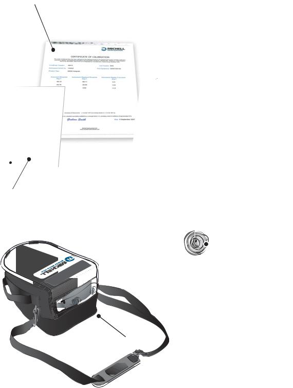
2.3MDM300 I.S. Accessories
The accessories for the MDM300 I.S. are shown in Figure 6. Items 1 to 7 are supplied as standard and item 8 is optional. Please check that all the standard components are present after unpacking. Report any shortages immediately.
1.Calibration certificate
2.User’s manual
3.Charger unit
4.Country specific mains lead
5.Gas Input/Output port adaptors
(three provided - two fitted to the instrument - see Figure 5)
6.Application Software CD
7.Quick-start card
8.Carrying case - made from anti-static materials suitable for use in hazardous areas (optional)
Three gas port adaptors are provided, two with a large bore orifice and one with a small bore orifice. Depending upon configuration, this permits the instrument to be run at either system pressure or atmospheric pressure and facilitates the connection of external flow monitoring and control.
NOTE: On delivery the two large orifice adaptors are fitted into the instrument’s gas ports (1 and 2) as shown in Figure 5. One small orifice adaptor is provided as a loose spare in the accessory pack (see Section 2.5).
.S.I -
Small orifice
Large orifice
21
Gas In |
Gas Out |
Figure 5 Gas Port Adaptors
10 |
97213 Issue 5, October 2017 |
MDM300 I.S. User’s Manual |
INSTALLATION |
|
|
|
|
1
MDM300 & MDM300 I.S. Quick Start Guide
Typical MDM300 Sampling Arrangement
SAMPLE FLOW
 1
1
 2
2
3
4
VENT
1 Coalescing Filter
2Particulate Filter
3Inlet Flow Control Valve
4Outlet Flow Control Valve
HIGH PRESSURE! High pressure gases are potentially hazardous. Energy stored in these
! JDVHV FDQ EH UHOHDVHG VXGGHQO\ DQG ZLWK H[WUHPH IRUFH +LJK SUHVVXUH V\VWHPV VKRXOG EH
DVVHPEOHG DQG RSHUDWHG RQO\ E\ SHRSOH ZKR KDYH EHHQ WUDLQHG LQ SURSHU VDIHW\ SUDFWLFHV
97244 Issue 02, July 2011
7
2
Hygrometer
. -I.S
|
|
4 |
. 1 |
|
Issue |
|
|
97213 |
2013 |
||
June |
|
|
|
3
4
 5
5
8 |
6 |
|
Figure 6 Accessories
Michell Instruments |
11 |
INSTALLATION |
MDM300 I.S. User’s Manual |
|
|
|
|
2.4Operational Requirements
Operational requirements are as follows:
Sample gas flow rate: |
0.2 to 0.5 Nl/min (0.5 to 1 scfh) |
Operating pressure: |
0 to 350 barg (0 to 5076 psig) |
2.4.1Environmental Requirements – MDM300 I.S. Instrument
Operating temperature range: -20 to +50°C (-4 to +122°F)
Humidity: |
0 to 100% RH (non-condensing) |
Altitude: |
Up to 2000m (6562 ft) |
2.4.2Charger Electrical Requirements
Charger supply voltage: |
100 to 240 V AC (+10%, -15%) |
|
50/60 Hz (±5%), 8 VA |
2.5Instrument Gas Connections
POSSIBLE INJURY! The tubing, valves and other apparatus ! attached to this instrument must be adequate for the
maximum pressure which will be applied, otherwise physical injury to the operator or bystander is possible.
Sample gas connections are made via the Gas In (2) and Gas Out (1) ports located on the rear of the instrument as shown in Figure 5.
The MDM300 I.S. is supplied with a large bore orifice fitting installed into the Gas In and Gas Out ports. These fittings have an 1/8” NPT female thread to allow the user to connect other components of their choice.
Atmospheric pressure or system pressure dew point can be measured depending on the configuration of the adaptor fittings as shown in Table 3.
For gas pressures outside the range 2.5 to 10 barg, the instrument requires external flow control components, as shown in Figure 8.
Dew point at |
Gas Inlet port |
Gas Outlet port |
Sample gas |
|
fitting |
fitting |
pressure |
||
|
||||
Atmospheric |
Small bore orifice |
Large bore orifice |
2.5 to 10 barg |
|
(36 to 145 psig) |
||||
|
|
|
||
|
|
|
|
|
System |
Large bore orifice |
Small bore orifice |
2.5 to 10 barg |
|
(36 to 145 psig) |
||||
|
|
|
||
|
|
|
|
|
Either (using |
|
|
0 to 350 barg |
|
other flow control |
Large bore orifice |
Large bore orifice |
||
(0 to 5076 psig) |
||||
components) |
|
|
||
|
|
|
||
|
Table 3 |
Adaptor Fittings |
|
12 |
97213 Issue 5, October 2017 |
MDM300 I.S. User’s Manual |
INSTALLATION |
|
|
|
|
2.5.1Gas Inlet /Outlet Fittings
HIGH PRESSURE! High pressure gases are potentially hazardous. Energy stored in these gases can be released
! suddenly and with extreme force. High pressure systems should be assembled and operated only by people who have
been trained in proper safety practices.
Before making a measurement, the gas fittings should be attached to the instrument as shown in Table 3.
1.Fit the required orifice fittings with supplied bonded seals. Ensure bonded seals are correctly seated in recessed grooves.
PTFE tape here
1/8” Swagelok
fitting h 


h
Adaptor
h |
Bonded seal |
h |
Figure 7 Bonded Seal Fitting
2.Fit any other adaptors that might be required.
3.If the small bore orifice fitting is not being utilized then one of the optional application kits could be fitted (as shown below).
.S.I
Figure 8 Gas Coupling Examples for Atmospheric Pressure Measurement
NOTE: The application kit shown above (excluding the orifice fittings) is not supplied as standard, but is part of a range of kits which can be ordered from Michell Instruments, on request.
NOTE: The bonded seals used for the MDM300 I.S. are Dowty part number 400-228-4490-74 (from Michell Instruments, part number MDM300-DS).
Michell Instruments |
13 |

INSTALLATION |
MDM300 I.S. User’s Manual |
|
|
|
|
2.6Connect External Sensors
The MDM300 I.S. can be configured for connection to a Michell Instruments’ Easidew I.S. transmitter (ATEX Baseefa 06ATEX0330X, IECEx BAS06.0090X), via the MDM300 I.S. Remote Sensor Interface, when the Easidew I.S. transmitter is installed within a hazardous area.
The MDM300 I.S. Remote Sensor Interface is a passive device. The combined terminal parameters of the MDM300 I.S. and of the barrier used with the Easidew I.S. system must not exceed the input terminal parameters of the Easidew I.S. as specified in the System Drawing (System Certificate No. Baseefa 07Y0027).
To view any of these certificates go to: http://www.michell.com
|
.IMDM300 |
|
|
|
.S |
 to Connect
MDM300 I.S.
REMOTE SENSOR INTERFACE
Connect to Easidew I.S. Sensor |
|
|
|
EASIDEW I.S. SYSTEM
Connect to
Figure 9 MDM300 I.S. Remote Sensor Interface
Refer to Appendix C (Hazardous Area Certification) for the MDM300 I.S. terminal parameters.
Figure 10 shows the connection of the MDM300 I.S. Remote Sensor Interface to the MDM300 I.S. and the Easidew I.S. transmitter.
HAZARDOUS AREA |
|
X |
|||||
REMOTE SENSOR |
h |
|
|
|
|
|
|
INTERFACE |
|
|
|
|
|
|
|
W |
MDM300 I.S. |
Connectto |
W |
||||
|
toConnect .S.IMDM300 |
Connect to Easidew I.S. Sensor |
|
||||
|
W |
REMOTE SENSOR INTERFACE |
|
W |
|||
|
|
|
W |
W |
|
|
|
|
|
|
|
|
|
|
|
|
|
|
20mA0Hz28Vdc |
|
|
|
|
|
|
|
|
|
|
|
|
|
|
|
|
|
|
|
|
|
|
|
EASIDEW.S.IDewPointTran |
|
|
|
|
|
|
|
,5NmEly,CambsUK |
|
|
|
|
|
|
|
|
|
|
|
|
h |
X SAFE AREA
EASIDEW I.S. SENSOR BARRIER ASSEMBLY
SYSTEM CERT
Baseefa 07Y0027
X
X

 -I.S.
-I.S.


EASIDEW I.S.
h
MDM300 I.S.
Figure 10 External Sensor Connection
14 |
97213 Issue 5, October 2017 |
 Loading...