


OptiPEAK TDL600
Process Moisture Analyzer
User’s Manual
97319 Issue 4.2
November 2018

Please fill out the form(s) below for each instrument that has been purchased.
Use this information when contacting Michell Instruments for service purposes.
Analyzer
Code
Serial Number
Invoice Date
Location of Instrument
Tag No
Analyzer
Code
Serial Number
Invoice Date
Location of Instrument
Tag No
Analyzer
Code
Serial Number
Invoice Date
Location of Instrument
Tag No

OptiPEAK TDL600
For Michell Instruments' contact information please go to www.michell.com
© 2018 Michell Instruments
This document is the property of Michell Instruments Ltd. and may not be copied or otherwise reproduced, communicated in any way to third parties, nor stored in any Data Processing System without the express written authorization of Michell Instruments Ltd.
|
|
OptiPEAK TDL600 User’s Manual |
|
|
|
||
|
|
||
Contents |
|
||
Safety ............................................................................................................................... |
|
vii |
|
|
Electrical Safety .......................................................................................................... |
vii |
|
|
Pressure Safety........................................................................................................... |
vii |
|
|
Toxic Materials ............................................................................................................ |
vii |
|
|
Repair and Maintenance .............................................................................................. |
vii |
|
|
Calibration (Factory Validation)..................................................................................... |
vii |
|
|
Safety Conformity ....................................................................................................... |
vii |
|
Abbreviations.................................................................................................................... |
viii |
||
1 |
INTRODUCTION ................................................................................................ |
1 |
|
|
1.1 |
Application......................................................................................................... |
1 |
|
1.2 |
Features ............................................................................................................ |
1 |
|
1.3 |
Theory of Operation ........................................................................................... |
2 |
|
1.3.1 |
Measurement Using a Laser ........................................................................... |
4 |
2 |
INSTALLATION .................................................................................................. |
6 |
|
|
2.1 |
Unpacking the Instrument................................................................................... |
6 |
|
2.2 |
Lifting and Handling ........................................................................................... |
7 |
|
2.3 |
Laser Safety....................................................................................................... |
7 |
|
2.4 |
Hazardous Area Safety........................................................................................ |
8 |
|
2.5 |
Electrical Safety.................................................................................................. |
9 |
|
2.5.1 |
Equipment Ratings and Installation Details...................................................... |
9 |
|
2.6 |
Pressure Safety ................................................................................................ |
11 |
|
2.7 |
Basic Installation Guidelines .............................................................................. |
11 |
|
2.8 |
Electrical Connections ....................................................................................... |
15 |
|
2.8.1 |
Power Connection ....................................................................................... |
15 |
|
2.8.2 |
Analog Outputs........................................................................................... |
16 |
|
2.8.3 |
Analog Inputs ............................................................................................. |
16 |
|
2.8.4 |
Alarm Relays............................................................................................... |
16 |
|
2.8.5 |
Modbus RTU / RS485 Connection ................................................................. |
17 |
|
2.9 |
Environmental Requirements............................................................................. |
17 |
|
2.10 |
Sample Conditioning Requirements.................................................................... |
18 |
|
2.10.1 |
Gas Connections ......................................................................................... |
18 |
|
2.10.2 |
Sample Flow Gas Handling Components ....................................................... |
18 |
|
2.11 |
Options............................................................................................................ |
21 |
|
2.11.1 |
Enclosure Heater Temperature Control (Outdoor systems ONLY)..................... |
21 |
|
2.11.2 |
Vortex Cooling (Outdoor systems ONLY) ....................................................... |
21 |
|
2.11.3 |
Trace Heated Sample Line ........................................................................... |
21 |
3 |
OPERATION .................................................................................................... |
22 |
|
|
3.1 |
Start-Up Procedure ........................................................................................... |
22 |
|
3.2 |
Shut Down Procedure ....................................................................................... |
23 |
|
3.3 |
User Interface .................................................................................................. |
24 |
|
3.3.1 |
Interface Controls ....................................................................................... |
24 |
|
3.3.2 |
‘Up/Down Arrow’ Keys ................................................................................. |
24 |
|
3.3.3 |
‘ENTER’ Key................................................................................................ |
25 |
|
3.3.4 |
‘ESC’ Key .................................................................................................... |
25 |
|
3.4 |
Description of Measured Parameters .................................................................. |
25 |
|
3.5 |
Default Settings................................................................................................ |
26 |
|
3.5.1 |
Advanced Menu default settings................................................................... |
26 |
|
3.6 |
Menu Structure ................................................................................................ |
27 |
|
3.7 |
Main Menu Screen ............................................................................................ |
28 |
|
3.7.1 |
Parameters Screen ...................................................................................... |
29 |
|
3.7.2 |
Display Screen ............................................................................................ |
30 |
|
3.7.3 |
Log Menu Screen ........................................................................................ |
31 |
|
3.7.4 |
About Screen.............................................................................................. |
32 |
|
3.7.5 |
Graph Screen.............................................................................................. |
32 |
iv |
97319 Issue 4.2, November 2018 |

OptiPEAK TDL600 User’s Manual |
|
|
3.7.6 |
Advanced Settings Screen............................................................................ |
33 |
3.7.6.1 |
Outputs Screen..................................................................................... |
34 |
3.7.6.2 |
Alarms Screen ...................................................................................... |
35 |
3.7.6.3 |
Inputs Screen ....................................................................................... |
38 |
3.7.6.4 |
Clock Screen......................................................................................... |
41 |
3.7.6.5 |
Modbus Screen ..................................................................................... |
42 |
3.7.6.6 |
Region Defaults Screen.......................................................................... |
43 |
3.7.6.7 |
N2-Mode (Measurement Mode) Screen ................................................... |
44 |
3.7.6.8 |
Safe Mode (Laser Disabled) Screen ........................................................ |
44 |
3.8 Enclosure Cover and User Interface ................................................................... |
45 |
|
4 MAINTENANCE ................................................................................................ |
46 |
|
4.1 Inspection of the Enclosure Cover...................................................................... |
47 |
|
4.2 Replacement of the Micro SD Data Logging Card ................................................ |
49 |
|
4.3 Membrane and Particulate Filter Element Replacement........................................ |
51 |
|
4.3.1 |
Service Intervals ......................................................................................... |
51 |
4.3.2 |
Installing the Filter Element and Membrane .................................................. |
51 |
4.3.3 |
Field measurement verification..................................................................... |
53 |
4.3.4 |
Long-term maintenance – Laser replacement................................................ |
54 |
Figures |
|
|
Figure 1 |
Beer Lambert Law ...................................................................................... |
3 |
Figure 2 |
Laser Scan ................................................................................................. |
4 |
Figure 3 |
System Block Schematic.............................................................................. |
5 |
Figure 4 |
Unpacking the TDL600................................................................................ |
6 |
Figure 5 |
Earthing Stud And Nut Washer Assembly ................................................... |
10 |
Figure 6 |
OptiPEAK Sampling System - Typical Indoor Version.................................... |
12 |
Figure 7 |
OptiPEAK Sampling System - Typical Intdoor Version................................... |
12 |
Figure 8 |
OptiPEAK Sampling System - Typical Outdoor Version ................................. |
13 |
Figure 9 |
OptiPEAK Sampling System - Typical Outdoor Version ................................. |
14 |
Figure 10 |
User Interface .......................................................................................... |
24 |
Figure 11 |
Up/Down Arrow Keys................................................................................ |
24 |
Figure 12 |
'ENTER’ Key ............................................................................................. |
25 |
Figure 13 |
‘ESC’ Key ................................................................................................. |
25 |
Figure 14 |
Menu Structure ........................................................................................ |
27 |
Figure 15 |
Main Menu Screen .................................................................................... |
28 |
Figure 16 |
Parameters Screen ................................................................................... |
29 |
Figure 17 |
Display Setup Screen ................................................................................ |
30 |
Figure 18 |
Data Logging Screen ................................................................................ |
31 |
Figure 19 |
Contact/About Screen............................................................................... |
32 |
Figure 20 |
Graph Screen ........................................................................................... |
32 |
Figure 21 |
Advanced Settings Screen ......................................................................... |
33 |
Figure 22 |
Output Screens ........................................................................................ |
34 |
Figure 23 |
Alarm Screens.......................................................................................... |
35 |
Figure 24 |
Typical Alarm Status Indication on the Run-Mode Screen............................. |
37 |
Figure 25 |
Input Screen ............................................................................................ |
38 |
Figure 26 |
Line Pressure Setup Screen ....................................................................... |
39 |
Figure 27 |
Spare Input Setup Screen ......................................................................... |
40 |
Figure 28 |
Set Date/Time Screen............................................................................... |
41 |
Figure 29 |
Modbus Settings Screen............................................................................ |
42 |
Figure 30 |
Region Defaults Screen............................................................................. |
43 |
Figure 31 |
N2-Mode (Measurement Mode) Screen ...................................................... |
44 |
Figure 32 |
Safe Mode (Laser Disabled) Screen............................................................ |
45 |
Figure 33 |
Dimensional Drawing - Indoor System Enclosure ........................................ |
58 |
Figure 34 |
Dimensional Drawing - Outdoor System Enclosure ...................................... |
59 |
Figure 35 |
Wiring Diagram Indoor System.................................................................. |
61 |
Figure 36 |
Wiring Diagram Outdoor System................................................................ |
63 |
Michell Instruments |
v |

|
|
OptiPEAK TDL600 User’s Manual |
|
Tables |
|
|
|
Table 1 |
Parameters Screen Parameters ................................................................... |
29 |
|
Table 2 |
Display Setup Screen Parameters................................................................ |
30 |
|
Table 3 |
Data Logging Screen Parameters ................................................................ |
31 |
|
Table 4 |
Output Screen Parameters ......................................................................... |
34 |
|
Table 5 |
Line Pressure Setup Screen Parameters....................................................... |
39 |
|
Table 6 |
Spare Input Setup Screen Parameters......................................................... |
40 |
|
Table 7 |
Set Date/Time Screen Parameters .............................................................. |
41 |
|
Table 8 |
Modbus Screen Parameters ........................................................................ |
42 |
|
Table 9 |
Region Default Parameters......................................................................... |
43 |
|
Table 10 |
N2-Mode Parameters ................................................................................. |
44 |
|
Appendices |
|
|
|
Appendix A |
Technical Specification ............................................................................... |
55 |
|
|
A.1 |
Dimensional Drawings.................................................................. |
56 |
|
A.2 |
Dimensional Drawings.................................................................. |
57 |
Appendix B |
Indoor Sampling System Wiring Diagram .................................................... |
59 |
|
Appendix C |
Outdoor Sampling System Wiring Diagram .................................................. |
61 |
|
Appendix D |
Flow Diagram............................................................................................ |
63 |
|
Appendix E |
Modbus Holding Register Map .................................................................... |
65 |
|
Appendix F |
Quality, Recycling, Compliance & Warranty Information................................ |
70 |
|
Appendix G |
Hazardous Area Certification ...................................................................... |
71 |
|
|
G.1 |
Product Standards ....................................................................... |
72 |
|
G.2 |
Product Certification .................................................................... |
72 |
|
G.3 |
Global Certificates/Approvals ........................................................ |
72 |
|
G.4 |
Special Conditions of Use ............................................................. |
72 |
|
G.5 |
Maintenance and Installation........................................................ |
73 |
Appendix H |
Return Document & Decontamination Declaration........................................ |
75 |
|
vi |
97319 Issue 4.2, November 2018 |

OptiPEAK TDL600 User’s Manual
Safety
This manual contains all the required information to install, operate and maintain the OptiPEAK TDL600 Process Moisture Analyzer. Prior to installation and use of this product, this entire manual should be read and understood. Installation and operation of this product should be carried out by suitably competent personnel only. The operation of this product must be in accordance with the terms of this manual and associated safety certificates. Incorrect installation and use of this product for other than its intended purpose will render all warranties void.
This product is intended for use in a Hazardous Area and is awarded an ATEX, IECEx and cQPSus Certificate. These certificates should be fully examined prior to installation or use of this product.
Where this hazard warning symbol appears in the following sections, ! it is used to indicate areas where potentially hazardous operations
need to be carried out and where particular attention to personal and personnel safety must be observed.
Electrical Safety
The instrument is designed to be completely safe when used with options and accessories supplied by the manufacturer for use with the instrument. The input power supply voltage limits are 90 to 264 V AC, 50/60Hz (dependent on chosen options).
Pressure Safety
DO NOT permit pressures greater than the safe working pressure to be applied directly to the instrument's sample cell. The specified working pressure is 0.7 to 1.4 bara (10 to 20.3 psia). Refer to the Technical Specifications in Appendix A.
Toxic Materials
The use of hazardous materials in the construction of this instrument has been minimized. During normal operation it is not possible for the user to come into contact with any hazardous substance which might be employed in the construction of the instrument. Care should, however, be exercised during maintenance and the disposal of certain parts.
Repair and Maintenance
The instrument must be maintained either by the manufacturer or an accredited service agent. Refer to www.michell.com for details of Michell Instruments’ worldwide offices contact information.
Calibration (Factory Validation)
Prior to shipment, the analyzer undergoes stringent factory calibration to traceable standards. Due to the inherent stability of the instrument, regular field calibration is not required under normal operating conditions. The analyzer should perform reliably for many years with just basic maintenance and housekeeping. Michell can provide a fully traceable factory calibration service for the instrument when required. Please contact your local Michell office or representative for further details (www. michell.com).
Safety Conformity
This product meets the essential protection requirements of the relevant EU directives. Further details of applied standards may be found in the product specification.
Michell Instruments |
vii |

OptiPEAK TDL600 User’s Manual
Abbreviations
The following abbreviations are used in this manual:
A |
ampere |
AC |
alternating current |
bara |
pressure unit (=100 kPa or 0.987 atm) |
barg |
pressure unit (=100 kPa or 0.987 atm) gauge |
°C |
degrees Celsius |
°F |
degrees Fahrenheit |
EU |
European Union |
ft |
feet |
hr |
hour |
kg |
kilogram(s) |
lbs |
pound(s) |
lb/MMscf |
pounds per million standard cubic feet |
LCD |
liquid-crystal display |
Nl/min |
normal liters per minute |
m |
meters |
mA |
milliampere |
max |
maximum |
*mg/m3 |
milligrams per cubic meter |
mm |
millimeters |
nm |
nanometers |
NPT(F) |
National pipe thread (female) |
PCB |
printed circuit board |
ppmV |
parts per million by volume |
psia |
pounds per square inch absolute |
psig |
pounds per square inch gauge |
RH |
relative humidity |
RS485 |
serial data transmission standard |
scfh |
standard cubic feet per hour |
sec |
seconds |
TDL |
Tuneable Diode Laser |
V |
Volt |
W |
Watts |
% |
percentage |
“ |
inch(es) |
ø |
diameter |
* mg/m3 refers to standard sm3 (i.e. 15°C at atmospheric pressure)
viii |
97319 Issue 4.2, November 2018 |
OptiPEAK TDL600 User’s Manual |
INTRODUCTION |
|
|
|
|
1 INTRODUCTION
The OptiPEAK TDL600 Tunable Diode Laser Analyzer employs the latest techniques in laser absorption spectroscopy and signal processing power to offer a robust high performance analyzer, designed specifically for the measurement of moisture in natural gas. The analyzer is fully hazardous area certified and delivers class-leading measurement performance, stability and detection sensitivity.
The complete OptiPEAK TDL600 Analyzer Sampling System can be located close to the gas sample take-off point in a potentially explosive environment - designated Zone 1 and Zone 2 hazardous area.
The indoor version Sampling System gas handling components are assembled on a 316 Stainless Steel plate suitable for wall mounting within a temperature controlled analyzer house.
The outdoor version Sampling System is housed within a stainless steel enclosure (304 or 316), with optional thermostatically controlled heating and cooling, for direct field installation in a 100% shaded location next to the process line (with overall environmental protection to IP66).
All sample gas wetted metallic parts are in AISI 316L stainless steel with Viton® soft parts that comply with the NACE standard MR-01-75 (latest edition). Tube fittings are type 316 Stainless Steel. All gas and cable entries are located in the base of the enclosure.
1.1Application
The measurement of moisture in natural gas streams is an essential and highly critical analysis for the natural gas industry. Gas companies need to meet specific quality standards for transmission, custody transfer and delivery. High levels of water in the gas increase the cost of transportation and lower the calorific value of the gas. In addition, excessive moisture content in the gas stream can lead to internal pipe corrosion and hydrate formation, requiring expensive pipe cleaning or 'pigging'. In severe cases, pipeline blockage can occur.
Although the analyzer is designed for the measurement of water in transmission quality natural gas backgrounds it has been configured for use with almost any natural gas stream. This provides full flexibility if, for example, the analyzer is later re-deployed to a different application. (See Section 3, Operation, for further details.)
1.2Features
•High Measurement Sensitivity
The OptiPEAK TDL600 features a lower detection limit (LDL) of 1 ppmV water content. This high sensitivity, coupled with the inherent fast response of the TDL optical measurement, provides an extremely fast, accurate and reliable non-contact gas measurement.
•D-MET – Dynamic Methane Compensation. BioGas Ready
Moisture measurement is virtually independent* of changes in the methane composition of the natural gas feed and accuracy is not reliant on manual software correction factors being applied.
The analyzer can be used with a wide range of background gas compositions. With increasing statutory requirements in many regions for Biomethane to be added to natural gas streams, the analyzer has been future proofed by being Biomethane ready.
* Over a methane concentration range of 40 - 100% CH4
Michell Instruments |
1 |

INTRODUCTION |
OptiPEAK TDL600 User’s Manual |
|
|
|
|
•Laser Lock System
Tunable diode lasers can drift. This means that the laser wavelength may slowly change with time and, eventually, may not precisely match the absorption peak of the water. This can lead to a reduction in sensitivity and analyzer drift. This inherent property of diode lasers is overcome in the OptiPEAK TDL600 by the built-in Laser lock system. This system monitors the optical profile of the gas absorption peaks to ensure the laser remains locked to the correct water absorption peak, maintaining a high integrity measurement at all times.
•Fast Response
Being a non-contact optical measurement, the analyzer offers fast response times, meaning no long wet-up or dry-down times in contrast to traditional moisture sensors. None of the sensing components are exposed to the gas stream, protecting them from any aggressive components or harmful contamination.
•HMI system
Provides a highly intuitive menu driven interface, utilizing a capacitive touch screen system, offering stylus-free setup and operation without the need for a 'hot work' permit to adjust settings or to perform validation checks.
1.3Theory of Operation
The OptiPEAK TDL600 uses the technique of absorption spectroscopy to measure the concentration of water vapor in the gas stream. Many gas molecules exhibit very specific resonant vibrations in the infrared region of the electromagnetic spectrum. If infrared energy, at the same resonant wavelength, is passed through these molecules, some of this energy will be absorbed. If a suitable detector is used to measure the amount of received energy, and the gas is contained within a cell of a known path length, then the gas concentration can be calculated. This can be expressed mathematically and is often referred to as the Beer-Lambert Law.
c = εAl
where:
A = absorbance
ε = extinction coefficient (absorption strength of gas at a specific wavelength) l = sample cell path length
c = gas concentration
This law states that, if the sample cell path length (l) is known, and the extinction coefficient of the water molecule (ε - a constant that describes how strongly a particular gas absorbs light at a specific wavelength) is known, then, if the absorbance of laser energy by the water molecules is measured (A), the water concentration (c) of the sample stream can be calculated. This gas law is the basis of all photometric gas absorption measurement.
2 |
97319 Issue 4.2, November 2018 |
OptiPEAK TDL600 User’s Manual |
INTRODUCTION |
|
|
|
|
Beer Lambert law
Absorbent concentration (c)
IO 
 IX
IX
Path length (l)
Figure 1 Beer Lambert Law
The Michell OptiPEAK TDL600 uses a tunable diode laser source to generate a narrow and coherent beam of near infrared (NIR) energy at the precise resonant wavelength of water vapor. Traditionally, infrared analyzers use broadband sources which generate a wide gamut of wavelengths. To make these analyzers as selective as possible to moisture only, optical filters have to be deployed to 'narrow' the range of wavelengths that are finally passed through the sample. These filters do not offer very high selectivity - they are quite broadband, which can lead to significant spectral interference, as other gas peaks close to the water absorption peaks are also detected, leading to cross interference, drift and general degradation in measurement performance.
In contrast, the laser has a bandwidth of less than 0.0001 nanometers. This means the laser is very selective in detecting only the water and not any other gases present in the gas stream.
This optical technique also has the advantage that the analyzer uses a non-contact method of measurement, i.e. there is no sensing element in contact with the gas stream. This offers a highly robust and reliable measurement, as only photons of light pass through the gas. This provides very fast response and no long wet-up or dry-down times.
Michell Instruments |
3 |
INTRODUCTION |
OptiPEAK TDL600 User’s Manual |
|
|
|
|
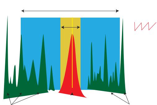
1.3.1Measurement Using a Laser
The diagram below illustrates the advantages of using a laser source, compared to a traditional broadband source.
The water absorption peak is shown in the center of the diagram (red area). The width of the laser beam is very narrow and is represented by the yellow line.
The laser wavelength is varied in order to scan across the water absorption peak (yellow area). By scanning the peak in this way, important information can be extracted, such as changes to the absorption peak caused by variation in the sample gas. This very precise scan range minimizes any overlap with nearby absorption bands, as would be the case with conventional broadband infrared sources and optical filters (blue area).
Typical broadband source bandwidth
Scan range
5 Hz ‘sawtooth’ laser scan
Conventional IR source gives very broad transmission
|
|
|
|
|
|
|
|
|
|
|
|
|
|
|
|
|
|
|
|
|
|
|
|
Potential interferant gases |
Gas absorption |
Potential interferant gases |
|||
|
|
(peak of interest) |
|
|
|
|
|
Bandwith |
|
|
|
|
|
approximately 0.05nm |
|
|
|
|
|
Figure 2 |
Laser Scan |
|
|
4 |
97319 Issue 4.2, November 2018 |
OptiPEAK TDL600 User’s Manual |
INTRODUCTION |
|
|
|
|
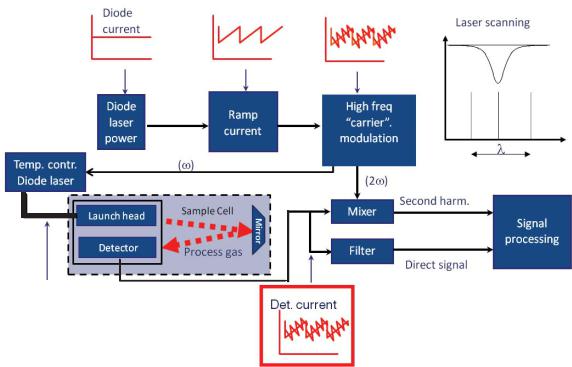
The schematic of the laser measurement system is shown in Figure 3 below. This highlights the major control and signal processing sections of the analyzer. The analyzer uses the WMS (Wavelength Modulation Spectroscopy) technique, in combination with proprietary signal processing algorithms to provide a selective response and high sensitivity to moisture.
Here, a single frequency, distributed feedback (DFB) laser diode is tuned by applying a current ramp to the laser. A further sinusoidal modulation is then applied. Lock-in detection is applied to the photo-detector signal obtained by passing the tuned laser radiation through the gas cell. The second harmonic signal from the lock-in detection is measured to recover the spectroscopic peak of interest. WMS offers a practical method of recovering weak signal changes from a dilute trace gas sample. WMS is becoming wide spread within the sector of natural gas monitoring and represents current state- of-the-art technology.
Diode |
|
|
|
|
Laser scanning |
|
|
current |
|
|
|
|
|
|
|
|
|
|
|
|
|
|
|
|
|
|
|
|
|
|
|
|
|
|
|
|
|
|
|
|
|
|
|
|
|
|
|
|
Diode |
|
|
Ramp |
|
|
|
|
|
|
|
High |
|
|
|
||
|
|
|
|
|
|
laser |
|
|
|
|
|
|
|
|
frequency |
|
|
|
||||
|
|
|
|
|
|
|
|
current |
|
|
|
|
|
|
|
|
|
|||||
|
|
|
|
|
|
power |
|
|
|
|
|
|
|
|
|
‘carrier’ |
|
|
|
|||
|
|
|
|
|
|
|
|
|
|
|
|
|
|
|
|
|
|
|
||||
|
Temperature |
|
|
|
|
|
|
|
|
|
|
|
modulation |
|
|
|
||||||
|
|
|
|
|
|
|
|
|
|
|
|
|
|
|
|
|
|
|
||||
|
controlled |
|
|
|
|
|
|
|
|
|
|
|
|
|
|
|
|
|
|
|||
|
|
|
|
|
|
|
|
|
|
|
|
|
|
|
|
|
|
|
||||
|
diode laser |
|
|
|
|
|
|
|
|
|
|
|
|
|
|
|
|
|
|
|||
|
|
|
|
|
|
|
|
|
|
|
|
|
|
|
|
|
|
|
|
|
||
|
|
|
|
|
|
|
|
|
|
|
|
|
|
|
|
|
|
|
Second harmonic |
|
|
|
|
|
|
|
|
|
|
|
|
|
|||||||||||||
|
|
|
|
|
|
|
|
|
|
|
|
|
|
|
|
|||||||
|
|
|
|
|
|
|
|
|
|
|
|
|
|
|
|
|
Mixer |
|
||||
|
|
|
|
Launch head |
|
|
|
|
|
|
|
|
|
|
|
|
Signal |
|||||
|
|
|
|
|
|
|
|
|
|
|
|
|
|
|
|
|||||||
|
|
|
|
|
|
|
|
|
|
|
|
|
|
|
|
|
||||||
|
|
|
|
|
|
|
|
|
|
|
|
|
|
|
|
|
|
|||||
|
|
|
|
|
|
|
|
|
|
|
|
|
|
|
|
|
|
|||||
|
|
|
|
|
|
|
|
|
|
|
|
|
|
|
|
|
|
|
|
|
|
|
|
|
|
|
|
|
|
|
|
|
|
|
|
|
|
|
|
|
|
|
|
|
processing |
|
|
|
|
|
Detector |
|
|
|||||||||||||||
|
|
|
|
|
|
|
|
|
|
|
|
|
|
Filter |
|
|
|
|
||||
|
|
|
|
|
|
|
|
|
|
|
|
|
|
|
|
|
|
|
||||
|
|
|
|
|
|
|
|
|
|
|
|
|
|
|
|
|
|
Direct signal |
|
|
||
|
|
|
|
|
|
|
|
|
|
|
|
|
|
|
|
|
|
|
|
|
||
|
|
|
|
|
|
|
|
|
|
|
|
|
|
|
|
|
|
|
|
|||
|
Fiber Optic cable |
|
|
|
|
|
|
|
|
|
|
|
|
|
|
|
||||||
|
|
|
|
|
|
|
|
|
|
|
|
|
|
|
|
|||||||
|
|
|
|
|
|
|
|
|
|
|
|
|
|
|
|
|||||||
|
|
|
Det. current |
|
|
|
|
|
|
|||||||||||||
|
|
|
|
|
|
|
|
|
|
|
||||||||||||
|
|
|
|
|
|
|
|
|
|
|
|
|
|
|
|
|
|
|
|
|
|
|
Figure 3 System Block Schematic
Michell Instruments |
5 |
INSTALLATION |
OptiPEAK TDL600 User’s Manual |
|
|
|
|
2 INSTALLATION
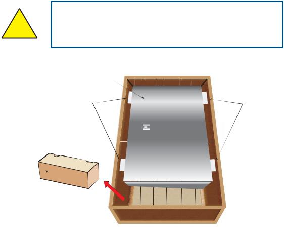
2.1Unpacking the Instrument
Open the crate and unpack carefully as follows:
WARNING:
! The instrument is heavy and should not be lifted alone.
Mechanical lifting aids may be required for larger systems.
|
3 |
2 |
2 |
|
1 
Figure 4 Unpacking the TDL600
1.Remove the accessories box (1).
2.Remove the spacer foam (2).
3.Remove the instrument enclosure (3) and set it down at the site of installation.
It is recommended to save all the packing materials for the purpose of returning the instrument for warranty claims.
The accessories box should contain the following items:
•Calibration Certificate
•Application Software CD
•User Manual
•CD containing System Documentation
6 |
97319 Issue 4.2, November 2018 |
OptiPEAK TDL600 User’s Manual |
INSTALLATION |
|
|
|
|
2.2Lifting and Handling
|
WARNING: |
! |
This product is in excess of 75kg (165lbs). |
Personnel must observe suitable lifting and handling |
|
|
precautions. |
|
|
The TDL600 is not designed as portable or transportable equipment. The product should be rigidly fixed in position as per the full installation instructions.
Appropriate lifting and handling techniques should be used during the installation process. Before commencing any lifting or handling ensure that its intended location is suitable and appropriately prepared. Make sure that mounting point design considerations have employed locally approved safety factors.
When handling and installing this instrument (particularly after removal from its packaging) ensure that it is not dropped, impacted or subjected to high levels of vibration or environmental conditions that may impair its operation.
2.3Laser Safety
This product contains a Diode Laser with an invisible beam, operating in the near infrared range. The laser as used in this product classifies it as a CLASS 1 product.
For the purposes of CDRH and FDA Registration the OptiPEAK TDL600 complies with 21CFR1040 with deviations pursuant to Laser Notice 50 and with IEC/EN 60825-1:2007.
WARNING:
This product is a CLASS 1 LASER PRODUCT.
Beware of Laser radiation.
Do not access the Laser.
Do not view the Laser directly.
WARNING:
Use of controls or adjustments, or performance of
! procedures other than those specified herein, may result in hazardous radiation exposure.
Michell Instruments |
7 |

INSTALLATION |
OptiPEAK TDL600 User’s Manual |
|
|
|
|
2.4Hazardous Area Safety
Refer to Appendix G for the Hazardous Area Certification of this product.
This product is fitted with a marking label that contains Hazardous Area information pertinent to the suitable location and installation.
During all installation and operation activities, local regulations and permitted working routines must be observed. Installation should only be performed by competent personnel and in accordance with IEC 60079-14:2007 and EN 60079-14:2008 or local equivalent.
Cable glands / conduit seals shall be installed in accordance with the manufacturer’s instructions.
Conduit seals used should be suitable for a reference pressure of 6.1 bar (89 psi). Repair and servicing of this equipment must only be carried out by the manufacturer.
|
WARNING: |
|
This product is certified safe for use in a Zone 1 and Zone 2 |
|
area only. This product must not be installed or used within |
|
a Zone 0 area. |
|
|
|
|
|
WARNING: |
|
This product must not be operated within an explosive |
|
atmosphere greater than 1.1 bara (16 psia). |
! |
|
|
|
WARNING: |
|
This product must not be operated within an enriched |
|
|
oxygen atmosphere (more than 21% oxygen content). |
|
|
|
|
|
WARNING: |
|
This product must not be operated outside of the |
|
temperature range of -20 to +55°C (-4 to +131°F) |
|
|
|
|
|
WARNING: |
|
The analyzer enclosure of this product provides Exd |
|
protection, partly through the threads used for mounting |
|
the lid, stopping plugs and cable gland. At all times effort |
|
should be made to ensure these threads are suitably |
|
protected from damage and that only appropriately rated |
|
mating parts are applied to them, in accordance with the |
|
certifying requirements. |
|
|
8 |
97319 Issue 4.2, November 2018 |

OptiPEAK TDL600 User’s Manual |
INSTALLATION |
|
|
|
|
2.5Electrical Safety
DANGER
Electric
Shock Risk
WARNING:
During the installation of this product, ensure that all applicable national and local electrical safety regulations are observed.
WARNING:
Always ensure that power is switched off prior to accessing the product for any purpose other than normal operation, or prior to disconnecting any cables.
2.5.1Equipment Ratings and Installation Details
The following mandatory statements refer to the Ex certified TDL600 Analyzer and sampling system.
This equipment must be supplied with a voltage in the range of 90 to 264 V AC, 50/60 Hz. Maximum power rating depends on chosen standard options, 80W to 250W.
All electrical connections to the analyzer are made through junction boxes, mounted on the panel of the sample system in accordance with Section 2.8.
Any power cable should be 3 core over sleeved, with minimum 0.5mm insulation and rated at 300 V. Cables should have Live (L), Neutral (N) and Earth [Ground] (E) conductors. Ensure suitably rated power supply cables and glands are used to ensure that electrical safety is maintained. Ensure the power supply can deliver sufficient power to meet the consumption requirements.
Any power supply terminals and voltages must be suitably separated from the other I/O requirements to this product.
Before applying power, perform a continuity test to ensure that the power supply cable and the TDL600 are effectively connected to the protective Earth.
Michell Instruments |
9 |
INSTALLATION |
OptiPEAK TDL600 User’s Manual |
|
|
|
|
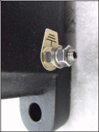
The protective Earth terminal is mounted internally and the Earth wire connected to it should never be disconnected. The analyzer enclosure is supplied with an external earth stud at the lower right hand side. This earth stud is connected to the sampling system earth using 4mm2 minimum earthing bonding.
Figure 5 Earthing Stud And Nut Washer Assembly
Fuse: A replacement fuse can be obtained by contacting Michell Instruments' technical support. Fuse rating = 5 x 20mm 2.5 A anti-surge to IEC 60127-2.
This measuring product is designed, where applicable and possible, to be in compliance with EN/BS/IEC61010 safety requirements or electrical equipment or measurement, control, and laboratory use. This product is designed to be safe at least under the following conditions: between a temperature range of -40 to +60°C (-40 to +148°F), in maximum 80% relative humidity for temperatures up to +31°C (+88°F) decreasing linearly to 50% RH at +50°C (+122°F). Supply voltages of ±10% and transient over voltages up to Overvoltage Category II. Pollution Degree 2. Altitudes up to 2000m. Outdoor mounting is permitted using suitably rated glands equivalent to NEMA 4 / IP66.
See Appendix A, Technical Specification, for full operating parameters.
NOTE: Do not remove or exchange any of the cables or electrical components supplied with this product. Doing so will invalidate all warranties.
There are no additional or special electrical safety requirements other than those referred to in this manual.
For location and mounting arrangements please refer to the relevant sections of this manual.
Installation of this equipment must include the provision of a suitable and locally positioned power isolation switch or circuit breaker. Indication of the purpose of the switch or circuit breaker is strongly recommended. An over-current protection device should be rated to a maximum of 3 A.
This equipment and all power isolation devices must be installed in a location and position that allows safe and easy access to their operation and is able to rigidly support the equipment.
10 |
97319 Issue 4.2, November 2018 |

OptiPEAK TDL600 User’s Manual |
INSTALLATION |
|
|
|
|
Do not install this equipment in a location that would expose it to impact or high levels of vibration.
Operation of this equipment, other than in a manner specified by the manufacturer, may impair the safety protections provided.
The safe installation of this equipment and any system incorporating this equipment is the responsibility of the installer. Ensure local regulations and requirements are referred to prior to any installation commencing.
2.6Pressure Safety
!
WARNING:
This product is used in conjunction with pressurized gases. Observe pressurized gas handling precautions.
Pressurized gas should only be handled by suitably trained personnel.
The TDL600 measurement chamber requires pressurized gas to be connected to it. Observe pressurized gas handling regulations. Only suitably trained personnel should carry out tasks that include the use of pressurized gas media.
The TDL600 measurement cell accepts a maximum sample pressure of 1.4 bara (20.3 psia).
2.7Basic Installation Guidelines
The OptiPEAK TDL600 Moisture Analyzer Sampling System gas handling components are assembled onto a stainless steel mounting plate suitable for wall mounting.
The outdoor version Sampling System provides environmental ingress protection to IP66 and should be mounted vertically, free of any appreciable vibration, in a permanently shaded position to prevent heating effects through sun radiation. The Sampling System enclosure can be specified with optional thermostatically controlled heating (fixed set point). Optional enclosure cooling, using a compressed-air-driven vortex tube and fixed set point thermostat, is recommended for installation in hot climates (>+45°C (>+113°F)).
NOTE: Any TDL being installed within a plant where it cannot vent to open atmosphere needs a flare line connection that runs to the highest point and enters the flare system from a topside connection. This is to prevent liquids present in the flare stack from draining back into the analyzer system.
NOTE: The actual detailed configuration will be shown in the as-built drawings provided with the shipped analyzer.
For start-up instructions refer to Section 3.
Michell Instruments |
11 |
INSTALLATION |
OptiPEAK TDL600 User’s Manual |
|
|
|
|
1 |
BV1 |
Ball Valve |
|
|
|
2 |
F2 |
Particulate Filter |
|
|
|
3 |
PR1 |
Pressure Regulator |
|
|
|
4 |
PG1 |
Pressure Gauge |
5 |
PR2 |
Pressure Gauge |
|
|
|
6 |
F2 |
Coalescing & Membrane Filter |
|
|
|
7 |
PR2 |
Pressure Regulator |
|
|
|
8 |
PG3 |
Pressure Gauge |
|
|
|
9 |
PRV1 |
Pressure Relief Valve |
|
|
|
10 |
FM1 |
Flowmeter |
|
|
|
11 |
AN1 |
Moisture Analyzer |
|
|
|
12 |
MV1 |
Metering Valve |
|
|
|
13 |
NV1 |
Needle Valve |
14 |
FM2 |
Flowmeter |
|
|
|
10 |
|
11 |
|
9 |
|
8 |
4 |
|
3 |
7 |
|
|
5 |
2 |
|
|
||
6 |
14 |
|
1 |
||
12 |
||
|
||
13 |
|
|
|
|
|
|
|
|
|
|
|
|
|
|
|
|
TP Connections |
|
|
|
|
|
|
|
|
|
|
|
|
|
|
|
|
TP4 |
|
TP2 |
TP1 |
TP3 |
|||||
TP1 |
Sample Gas Inlet |
1/4” NPT (F) |
|
|
|
|
|
|
|
|
|
|
|
|
|
|
|
|
|
|
|
|
|
||||
|
|
|
|
|
|
|
|
|
|||||
TP2 |
Sample Gas Outlet |
1/4” NPT (F) |
|
|
|
|
|
|
|
|
|
|
|
|
|
|
|
|
|
|
|
|
|||||
TP3 |
Bypass Flow Gas Outlet |
1/4” NPT (F) |
|
|
|
|
|
|
|
|
|
|
|
|
|
|
|
|
|
|
|
|
|||||
TP4 |
Letdown Gas Vent/Drain |
1/4” NPT (F) |
|
|
|
|
|
|
|
|
|
|
|
|
|
|
|
|
|
|
|
|
|
|
|
|
|
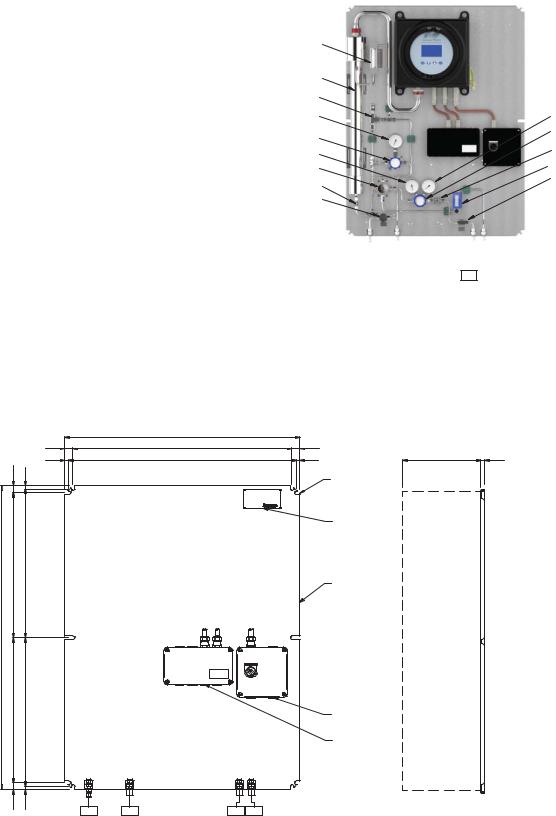
Figure 6 OptiPEAK Sampling System - Typical Indoor Version
|
|
750.0 |
|
|
|
|
|
25.0 |
700.0 CRS |
|
25.0 |
|
|
|
12.0 |
726.0 CRS |
|
12.0 |
250.0 |
12.0 |
22.0 |
10.0 |
|
|
|
MIN. CLEARANCE |
|
|
|
|
MOUNTING HOLES |
|
||
|
|
|
|
|
(10x 11mm) |
|
|
|
|
|
MODEL: OPTIPEAK TDL600 |
|
|
|
|
|
|
TYPE: PROCESS MOISTURE ANALYZER |
|
|
|
|
|
|
SERIAL NUMBER : nnnnnn /2017 |
|
|
|
|
|
|
WO NUMBER : BC45565 |
|
|
|
|
|
|
www.michell.com |
|
|
|
|
|
|
|
316SS NAMEPLATE |
|
463.0 CRS |
475.0 CRS |
|
|
|
316SS MOUNTING |
|
|
|
|
|
|
|
|
|
|
|
|
|
PLATE |
|
970.0 |
|
|
|
|
|
|
CRS |
CRS |
|
|
|
|
|
463.0 |
475.0 |
|
|
|
POWER INLET |
|
|
|
|
|
|
CABLE ENTRY |
|
|
|
|
|
|
(M20) |
|
|
|
|
|
|
SIGNAL OUTPUTS |
|
|
|
|
|
|
CABLE ENTRIES |
|
|
|
|
|
|
(2 x M20) |
|
22.0 |
10.0 |
TP02 |
TP01 |
TP03 |
|
|
|
TP04 |
|
|
Figure 7 OptiPEAK Sampling System - Typical Indoor Version
12 |
97319 Issue 4.2, November 2018 |
OptiPEAK TDL600 User’s Manual |
INSTALLATION |
|
|
|
|
1 |
BV1 |
Ball Valve |
|
|
|
|
|
2 |
F2 |
Particulate Filter |
|
|
|
|
|
3 |
PR1 |
Pressure Regulator |
|
|
|
|
|
4 |
PG1 |
Pressure Gauge |
|
5 |
PG2 |
Pressure Gauge |
|
|
|
|
|
6 |
F2 |
Coalescing & Membrane Filter |
|
|
|
|
|
7 |
PR2 |
Pressure Regulator |
|
|
|
|
|
8 |
AN1 |
Pressure Gauge |
|
|
|
|
|
9 |
FM1 |
Pressure Relief Valve |
|
|
|
|
|
10 |
PRV1 |
Flowmeter |
|
|
|
|
|
11 |
TS1 |
Moisture Analyzer |
|
|
|
|
|
12 |
MV1 |
Metering Valve |
|
|
|
|
|
13 |
FM2 |
Needle Valve |
|
|
|
|
|
14 |
NV1 |
Flowmeter |
|
|
|
|
|
15 |
HT |
Enclosure Heater |
|
|
|
|
|
16 |
TS1 |
Thermostat |
|
|
|
|
|
17 |
SOV1 |
Solenoid Valve |
|
|
|
|
|
18 |
TH |
Trace Heating |
|
|
|
|
|
|
|
|
|
|
|
TP Connections |
|
|
|
|
|
TP1 |
Sample Gas Inlet |
1/4” NPT (F) |
|
|
|
|
|
TP2 |
Sample Gas Outlet |
1/4” NPT (F) |
|
|
|
|
|
TP3 |
Bypass Flow Gas Outlet |
1/4” NPT (F) |
|
|
|
|
|
TP4 |
Letdown Gas Vent/Drain |
1/4” NPT (F) |
|
|
|
|
|
TP5 |
Vortex Cooler Inlet |
1/4" NPT (F) |
|
|
|
|
|
10 |
|
11 |
|
9 |
16 |
|
|
8 |
4 |
|
3 |
7 |
|
|
5 |
2 |
|
|
||
6 |
14 |
|
1 |
||
12 |
||
15 |
||
13 |
||
|
||
|
17 |
|
|
18 |
|
|
|
|
|
|
|
|
|
|
|
|
|
|
|
|
|
|
|
|
|
|
|
|
|
|
TP4 |
|
TP2 |
|
TP1 |
TP3 |
|
TP5 |
|||||
Figure 8 OptiPEAK Sampling System - Typical Outdoor Version
Michell Instruments |
13 |
INSTALLATION |
OptiPEAK TDL600 User’s Manual |
|
|
|
|
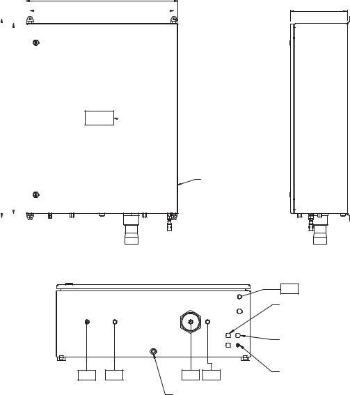
1045 |
|
|
|
1000 |
|
|
|
|
|
||
|
|
|
|
|
|
|
|
800
758 |
300.0 |
|
|
 MOUNTING HOLES (4x 10mm)
 316SS NAMEPLATE
ENCLOSURE (NOTE 1)
|
|
|
|
TP05 |
|
|
|
|
SIGNAL OUTPUTS |
|
|
|
|
CABLE ENTRIES |
|
|
|
|
(2 x M20) |
|
|
|
|
POWER INLET |
|
|
|
|
CABLE ENTRY |
|
|
|
|
(M20) |
TP04 |
TP02 |
TP01 |
TP03 |
EARTH STUD |
|
||||
|
|
BREATHER/DRAIN |
|
|
TP1 |
Sample Gas Inlet |
1/4” NPT (F) |
|
|
|
TP2 |
Sample Gas Outlet |
1/4” NPT (F) |
|
|
|
TP3 |
Bypass Flow Gas Outlet |
1/4” NPT (F) |
TP4 |
Letdown Gas Vent/Drain |
1/4” NPT (F) |
|
|
|
TP5 |
Vortex Cooler Inlet |
1/4" NPT (F) |
|
|
|
Figure 9 OptiPEAK Sampling System - Typical Outdoor Version
14 |
97319 Issue 4.2, November 2018 |

OptiPEAK TDL600 User’s Manual |
INSTALLATION |
|
|
|
|
2.8Electrical Connections
All electrical connections to the TDL600 are made through junction boxes JB1 & JB2
(ATEX, IECEx and NEC500 Class I, Division 2 versions only).
WARNING:
! Once the mains power connections are made to JB1 the heaters and vortex cooling solenoid (if fitted) will be
energized.
This includes:
•Power Connection
•Analog Outputs
•Analog Inputs (line pressure transmitter)
•Alarm Relays
•Modbus RTU / RS485 Connection
For the wiring diagram, consult the appropriate Appendix, depending on whether the TDL600 was supplied with the indoor sample system, or the outdoor sample system:
Indoor Sample System |
Appendix B |
Outdoor Sample System |
Appendix C |
2.8.1Power Connection
A single-phase AC mains power supply is required to operate the Analyzer and Sampling System. The analyzer power supply can accommodate voltages from 90 to 264 V AC, 50/60 Hz. If enclosure heating or cooling options are selected, these will have defined voltage and wattage requirements.
The factory-set power supply voltage is indicated on a yellow label located on the rear panel.
NOTE: The user cannot change the specified power supply voltage.
Cable connections are made onto terminals within the Power Circuits junction box. Cable entry into the junction box is provide via M20 threaded holes (fitted with certified stopping plugs). Suitably certified cable glands should be used (not supplied).
The power connection is made through JB1 (ATEX, IECEx and NEC500 Class I, Division 2 versions only) – refer to the appropriate Appendix.
Michell Instruments |
15 |

INSTALLATION |
OptiPEAK TDL600 User’s Manual |
|||||||||
|
|
|
|
|
|
|
|
|
|
|
|
|
|
|
|
|
|
|
|
|
|
Terminals are marked: |
|
|
||||||||
|
|
|
|
|
|
|
|
|
|
|
|
Terminal No. |
Power Supply |
|
|||||||
|
|
|
|
|
|
|
|
|
|
|
|
1 |
|
|
|
Live |
|
||||
|
|
|
|
|
|
|
|
|
|
|
|
5 |
|
|
|
Neutral |
|
||||
|
|
|
|
|
|
|
|
|
|
|
|
|
|
|
|
|
|
|
|
Earth |
|
|
|
|
|
|
|
|
|
|
|
|
|
|
|
|
|
|
|
|
|
|
|
|
|
|
|
|
|
|
|
|
|
|
|
|
|
|
|
|
|
|
|
|
|
NOTE: An earth stud is provided in the base of the enclosure. This must be used to earth bond the Sampling System.
A power isolator switch is provided on the Power Circuits junction box for local power isolation of the OptiPEAK TDL600 Moisture Analyzer (Main Unit only) for maintenance or servicing. NOTE: This switch isolates the analyzer but does not isolate power from ancillaries such as the heating/cooling circuits where fitted.
2.8.2Analog Outputs
Three 2-wire analog outputs are provided that can be configured to represent any of the directly measured or calculated output parameters. These outputs are active, selfpowered from the analyzer and can be set as either 0-20mA or 4-20mA.
For an overview of the analog output menu, refer to Section 3.7.6.1.
The analog output connections are made through JB2 (ATEX, IECEx and NEC500 Class I, Division 2 versions only) – refer to the appropriate Appendix.
2.8.3Analog Inputs
Connection for process line pressure transmitter (optional).
Enables dynamic pressure compensation for calculation of moisture content units.
Input 1 12 V DC excitation power provision for loop powered 4-20mA, 2-wire transmitter. Transmitter must be able to function from 12 V DC excitation, such as typical devices requiring 8 - 30 V DC.
Internal sensing resistor 100 Ω.
Input 2 No function
2.8.4Alarm Relays
Three alarm relays are provided that can be triggered by any of the directly measured or calculated output parameters. Each alarm relay has Common (CO), Normally Open (NO) and Normally Closed (NC) contacts.
For detailed information on the alarms refer to Section 3.7.6.2.
The alarm relay connections are made through JB2 (ATEX, IECEx and NEC500 Class I, Division 2 versions only) – refer to the appropriate Appendix.
16 |
97319 Issue 4.2, November 2018 |

OptiPEAK TDL600 User’s Manual |
INSTALLATION |
|
|
|
|
2.8.5Modbus RTU / RS485 Connection
The TDL600 features an RS485 port for digital communication, and uses a subset of the Modbus RTU protocol. The RS485 connection should be configured with the following parameters:
Parameter |
Value |
|
|
Baud Rate |
9600bps |
|
|
Data Bits |
8 |
|
|
Parity |
None |
|
|
Stop |
Bits 2 |
|
|
A full list of Modbus registers can be found in Appendix E.
The RS485 connection is made through JB2 (ATEX, IECEx and NEC500 Class I, Division 2 versions only) – refer to the appropriate Appendix.
2.9Environmental Requirements
The environmental requirements of the analyzer (complete with sampling system) are as follows:
Temperature
Indoor version +10 to +45°C (+50 to +113°F) Outdoor version -20 to +45°C (-4 to +113°F)
Outdoor version with enclosure cooling option -20 to +55°C (-4 to +131°F)
Temperature (Storage) |
-30 to +60°C (-22 to +140°F) |
Relative Humidity |
Less than 90% RH |
If installed outside, the analyzer must be in a shaded position to prevent heating effects through sun radiation.
Michell Instruments |
17 |

INSTALLATION |
OptiPEAK TDL600 User’s Manual |
|
|
|
|
2.10Sample Conditioning Requirements
Sample extraction, handling and conditioning techniques are of critical importance to assure optimal performance and reliability of all gas analyzers that accurately quantify specific components within a process gas composition. Michell Instruments' recommendations and requirements in relation to the OptiPEAK TDL600 are outlined below.
Michell Instruments offers a range of sample extraction probes and sample conditioning systems that have been selected and designed to exceed these minimum requirements. For further information and advice please contact your local Michell office or distributor
– refer to contact details on www.michell.com.
2.10.1 Gas Connections
Ensure that the process sample gas supply line is well flushed through to clear any liquids and debris present, prior to connection to the Sampling System.
Connections are as follows - refer to Flow Diagram in Appendix D:
• |
TP1 |
Sample Gas Inlet |
• |
TP2 |
Sample Gas Outlet |
• |
TP3 |
Bypass Outlet |
• |
TP4 |
System Vent/Drain |
TP1 to TP3 are 1/4” NPT(F), TP4 is 1/4" OD.
2.10.2Sample Flow Gas Handling Components
The sample flow gas handling components are as follows:
•Gas Inlet Isolation Valve (BV1):
Allows user to manually isolate the system from the process sample gas supply line for maintenance or servicing.
•Particulate Filter (F1):
Provides protection to regulator from particulates
•Line Pressure Gauge (PG1):
Indicates the sample gas line pressure.
•Pressure Regulator 0-35 Bar (PR1):
Allows the user to manually set the sample gas analysis pressure for moisture measurement. 1st stage pressure regulation.
•Regulated Pressure Gauge (PG2)
Indicates pressure set on PR1.
18 |
97319 Issue 4.2, November 2018 |
OptiPEAK TDL600 User’s Manual |
INSTALLATION |
|
|
|
|
•Particulate/Coalescing Filter (F2):
Provides system protection from contamination of entrained liquids and particulates using membrane filtration.
•Pressure Regulator 0-4 Bar (PR2):
2nd stage pressure regulation for moisture measurement.
•Input Pressure Gauge (PG3):
Indicates cell input pressure as set at PR2.
•Insert Pressure Relief Valve (PRV1)
Protects AN1 from over pressure
•Metering Valve (MV1):
Allows the user to manually set the sample gas flowrate into the TDL gas cell.
•Moisture Analyzer (AN1):
TDL600 Process Moisture Analyzer
•Flowmeter (FM1):
Provides indication of the sample gas flow rate through the TDL gas cell.
•System Drain Needle Valve (NV1):
Allows the user to manually letdown the sample gas pressure trapped in the system for maintenance or servicing.
The bypass flow gas handling components are as follows:
•Bypass Flowmeter & Valve (FM2):
Allows the user to manually set and provide indication of the bypass gas flow rate across the membrane filter.
Sample Extraction and Impulse Tubing
An insertion probe, with tip positioned within the central one-third of the crosssectional area of the pipe, should be used to extract a sample with a composition that is representative of the majority of gas flowing within the pipeline. Attention should be given to the installation of impulse tubing connecting from the sample probe to the analyzer sample conditioning system. Analytical grade acid-etched stainless steel tubing should be used, which has a low moisture sorption capacity. Tube size should be 1/8" or 3mm diameter, or 1/4” or 6mm as a maximum, to ensure that sample transportation delay time is kept to a minimum. Likewise, to ensure the best dynamic response of the complete installed analyzer system, the positioning of the analyzer with sample conditioning system should be as close to the sample extraction probe as possible.
Michell Instruments |
19 |
 Loading...