

Page 1
XZR400 Series
Oxygen Analyzers
User’s Manual
97472 Issue 3
August 2018
Page 2
Please fi ll out the form(s) below for each instrument that has been purchased.
Use this information when contacting Michell Instruments for service purposes.
Instrument
Code
Serial Number
Invoice Date
Location of Instrument
Tag No
Instrument
Code
Serial Number
Invoice Date
Location of Instrument
Tag No
Instrument
Code
Serial Number
Invoice Date
Location of Instrument
Tag No
Page 3
© 2018 Michell Instruments
This document is the property of Michell Instruments Ltd. and may not be copied or
otherwise reproduced, communicated in any way to third parties, nor stored in any Data
Processing System without the express written authorization of Michell Instruments Ltd.
For Michell Instruments' contact information please go to
www.michell.com
Page 4

XZR400 Series User’s Manual
iv 97472 Issue 3, August 2018
Contents
Safety .............................................................................................................................. viii
Electrical Safety ......................................................................................................... viii
Pressure Safety .......................................................................................................... viii
Temperature Safety .................................................................................................... viii
Toxic Materials ........................................................................................................... viii
Repair and Maintenance ............................................................................................. viii
Calibration ................................................................................................................. viii
Safety Conformity ...................................................................................................... viii
Abbreviations ......................................................................................................................ix
Warnings ............................................................................................................................ x
1 INTRODUCTION ................................................................................................1
1.1 Operating Principle .......................................................................................... 2
1.2 The MSRS Technology...................................................................................... 3
2 INSTALLATION ..................................................................................................6
2.1 Unpacking the Analyzer ................................................................................... 6
2.2 Preparation ..................................................................................................... 6
2.3 Dimensions - XZR400A1 ................................................................................... 7
2.3.1 Installing the XZR400A1 .............................................................................. 7
2.4 Dimensions - XZR400A2 ................................................................................... 8
2.4.1 Installing the XZR400A2 .............................................................................. 9
2.5 Dimensions - XZR400A3 ................................................................................. 10
2.6 Dimensions - XZR400A4 ................................................................................. 10
2.7 Operating Requirements ................................................................................ 11
2.7.1 Environmental Requirements ..................................................................... 11
2.7.2 Electrical Requirements ............................................................................. 11
2.7.3 Gas Requirements .................................................................................... 11
2.7.4 Sampling System ...................................................................................... 11
2.8 Connections to the XZR400A1 ........................................................................ 12
2.8.1 Front Panel .............................................................................................. 12
2.8.2 Back Panel ............................................................................................... 12
2.8.3 Gas Inlet, Outlet and Bypass Gas Connections ............................................ 13
2.8.4 Electrical Terminal Block ............................................................................ 14
2.8.5 D-Sub DE9 plug ....................................................................................... 14
2.8.6 Pluggable 8 pins electrical connector ......................................................... 14
2.8.7 Sample Path ............................................................................................ 15
2.8.7.1 Signal Processing Path ........................................................................... 17
2.9 Connections to the XZR400A2 ........................................................................ 18
2.9.1 Gas Sample Inlet and Outlet Fittings .......................................................... 19
2.9.2 Electrical Terminal Block ............................................................................ 20
2.9.3 D-Sub DE9 plug ....................................................................................... 20
2.9.4 D-Sub DA15 plug ...................................................................................... 21
2.9.5 Sample Path ............................................................................................ 21
2.9.6 Signal Processing Path .............................................................................. 22
2.9.7 Alarm Outputs .......................................................................................... 22
2.10 Connections to the XZR400A3 ........................................................................ 23
2.10.1 Front Panel .............................................................................................. 23
2.10.2 Side Panel ................................................................................................ 24
2.10.3 Electrical Terminal Block ............................................................................ 25
2.11 Connections to the XZR400A4-Transportable .................................................... 26
2.11.1 Electrical Terminal Block ............................................................................ 27
2.11.2 D-Sub DE9 Type Plug ................................................................................ 27
Page 5

XZR400 Series User’s Manual
Michell Instruments v
2.12 Mains Power Supply - XZR400A1, XZR400A3 & XZR400A4 ................................ 28
2.12.1 Analog Outputs Connections ..................................................................... 29
2.12.2 Alarm Output Connections ........................................................................ 30
2.13 Gas Connection ............................................................................................. 31
3 OPERATION ...................................................................................................32
3.1 General Operational Information ..................................................................... 32
3.2 Powering-up the System ............................................................................... 33
3.3 Warm-Up Period ............................................................................................ 34
3.4 Main Screen .................................................................................................. 36
3.5 Control Parameters Display ............................................................................ 37
3.5.1 Confi guration ........................................................................................... 38
3.5.2 Changing the Access Code ........................................................................ 39
3.6 The Main (Expert) Menu ................................................................................ 41
3.6.1 Analog 1 .................................................................................................. 42
3.6.2 Alarms ..................................................................................................... 43
3.6.3 Auto Adjustment (Optional) ....................................................................... 45
3.6.4 System .................................................................................................... 49
3.6.5 Total Pressure Correction (Optional)........................................................... 51
3.6.6 COMM ..................................................................................................... 52
3.6.6.1 RS232 .................................................................................................. 52
3.6.6.2 RS485 .................................................................................................. 52
3.6.7 Flow ........................................................................................................ 53
4 CALIBRATION ..................................................................................................54
4.1 Defi nitions .................................................................................................... 55
4.1.1 ADJUSTMENT / Calibration Screen Pages 3.2, 3.2.1, 3.2.2 & 3.2.3 ............... 56
4.1.2 Diagnosis of the MSRS Sensor Status - Screen pages 3.2.4 to 3.2.7 ............. 59
5 MAINTENANCE ................................................................................................62
5.1 Troubleshooting Guide / Failure Analysis ......................................................... 62
Tables
Table 1 XZR400 Series MSRS Assembly .....................................................................5
Table 2 RS232 Commands ..................................................................................... 75
Page 6

XZR400 Series User’s Manual
vi 97472 Issue 3, August 2018
Figures
Figure 1 Zirconia Sensor Operating Principle ..............................................................3
Figure 2 MSRS Sensor..............................................................................................4
Figure 3 MSRS Dimensions .......................................................................................4
Figure 4 MSRS Wiring ..............................................................................................4
Figure 5 XZR400 Series MSRS Assembly ....................................................................5
Figure 6 Dimensions - XZR400A1 ..............................................................................7
Figure 7 Dimensions - XZR400A2 ..............................................................................8
Figure 8 Dimensions - XZR400A2 with External Pump Option ......................................9
Figure 9 Dimensions - XZR400A3 ............................................................................10
Figure 10 Dimensions - XZR400A4 ............................................................................10
Figure 11 Front Panel XZR400A1 ..............................................................................12
Figure 12 Back Panel XZR400A1 ...............................................................................12
Figure 13 Gas Circuit Diagram for Rack Version .........................................................13
Figure 14 Gas Circuit Diagram for Rack & Pump Version .............................................13
Figure 15 Electrical Terminal Block XZR400A1 ............................................................14
Figure 16 Sample Path XZR400A1 .............................................................................15
Figure 17 Sample Path with Pump Fitted XZR400A1 ...................................................16
Figure 18 Connections XZR400A2 .............................................................................18
Figure 19 Gas Circuit Diagram for XZR400A2 .............................................................19
Figure 20 Electrical Terminal Block XZR400A2 ............................................................20
Figure 21 XZR400A2 Sample Path .............................................................................21
Figure 22 Connections Front Panel - XZR400A3 .........................................................23
Figure 23 Connections Side Panel - XZR400A3 ...........................................................24
Figure 24 Electrical Terminal Block XZR400A3 ............................................................25
Figure 25 Connections Front Panel - XZR400A4 .........................................................26
Figure 26 Electrical Terminal Block XZR400A4 ............................................................27
Figure 27 D-Sub DE9 Plug - XZR400A4 ..................................................................... 27
Figure 28 Power Input Socket ..................................................................................28
Figure 29 Start-up Screen ........................................................................................34
Figure 30 Oven Temperature Screen .........................................................................34
Figure 31 Sample Flow Adjustment ...........................................................................35
Figure 32 Main Screen .............................................................................................36
Figure 33 Control Parameters Screen ........................................................................ 37
Figure 34 Main Menu Access Screen .........................................................................38
Figure 35 Main Menu Screen ....................................................................................38
Figure 36 Main Menu Screen ....................................................................................41
Figure 37 Analog Output Screen ...............................................................................42
Figure 38 Alarm Screen (Main) .................................................................................43
Figure 39 Alarm Screen (Alarm 1) .............................................................................44
Figure 40 Auto Adjustment Screen ...........................................................................45
Figure 41 Pressure Correction Screen .......................................................................51
Figure 42 Comm Screen ..........................................................................................52
Figure 43 Flow Correction Screen .............................................................................53
Figure 44 Calibration Procedure with XZR400A1 ........................................................54
Figure 45 Screen Page 3.2 ....................................................................................... 56
Figure 46 Screen Page 3.2.1 ....................................................................................56
Figure 47 Screen Page 3.2.2 ....................................................................................57
Figure 48 Screen Page 3.2.3 ....................................................................................58
Figure 49 Screen Page 3.2.8 ....................................................................................58
Figure 50 Screen Page 3.2.4 ....................................................................................59
Figure 51 Screen Page 3.2.5 ....................................................................................59
Figure 52 Screen Page 3-2-6 ....................................................................................60
Figure 53 Screen Page 3-2-7 ....................................................................................60
Figure 54 Pressure Correction Screen .......................................................................79
Page 7

XZR400 Series User’s Manual
Michell Instruments vii
Appendices
Appendix A Technical Specifi cations .............................................................................. 67
Appendix B Modbus (RTU) over RS485 ......................................................................... 70
B.1 Port Confi guration ........................................................................ 70
B.2 Hardware Confi guration ............................................................... 70
B.3 RS485 Register Map .....................................................................71
Appendix C RS232 Serial Output .................................................................................. 74
C.1 Port Confi guration ........................................................................ 74
C.2 Hardware Confi guration ............................................................... 74
C.3 RS232 Command List ................................................................... 75
Appendix D Extended Operating Range - (Optional) ...................................................... 77
Appendix E Process Pressure Correction - (Optional) ....................................................79
E.1 Process Pressure Correction Input Connections .............................. 79
Appendix F Flow Fault Contact - (Optional) ................................................................... 81
F.1 Flow Fault Output Connections ..................................................... 81
Appendix G Commutable Scale (Auto-Ranging) .............................................................83
Appendix H Optional moisture sensor ...........................................................................85
Appendix I Quality, Recycling & Warranty Information ...................................................88
Appendix J Analyzer Return Document & Decontamination Declaration ..........................90
Figure 55 Main Page ................................................................................................85
Figure 56 Control Parameters Page ...........................................................................85
Figure 57 Main Menu ............................................................................................... 85
Figure 58 DP Sensor Page ........................................................................................86
Page 8

XZR400 Series User’s Manual
viii 97472 Issue 3, August 2018
Safety
The manufacturer has designed this equipment to be safe when operated using the procedures
detailed in this manual. The user must not use this equipment for any other purpose than that
stated. Do not apply values greater than the maximum value stated.
This manual contains operating and safety instructions, which must be followed to ensure the safe
operation and to maintain the equipment in a safe condition. The safety instructions are either
warnings or cautions issued to protect the user and the equipment from injury or damage. Use
qualifi ed personnel and good engineering practice for all procedures in this manual.
Electrical Safety
The instrument is designed to be completely safe when used with options and accessories
supplied by the manufacturer for use with the instrument. The input power supply voltage is 90
to 264 V A C, 47/63 Hz. Refer to labels on instrument or calibration certifi cate.
Pressure Safety
DO NOT permit pressures exceeding 2 barg (29 psig) to be applied to the instrument. This maximum
pressure applies to all versions of the instrument.
Temperature Safety
During operation some parts of the instrument can be at very high temperatures.
Toxic Materials
The use of hazardous materials in the construction of this instrument has been minimized. During
normal operation it is not possible for the user to come into contact with any hazardous substance
which might be employed in the construction of the instrument. Care should, however, be exercised
during maintenance and the disposal of certain parts. Long exposure or breathing of the calibration
gases may be dangerous.
Repair and Maintenance
The instrument must be maintained either by the manufacturer or an accredited service agent. Refer
to www.michell.com for details of Michell Instruments’ worldwide offi ces contact information.
Calibration
The recommended calibration (or verifi cation) interval for the analyzer is 1 to 3 months depending
on the location and application in which the instrument is used.
Safety Conformity
This product carries the CE mark and meets the requirements of relevant European safety directives.
Page 9

XZR400 Series User’s Manual
Michell Instruments ix
Abbreviations
The following abbreviations are used in this manual:
AC alternating current
A Ampere
barg pressure unit (=100 kP or 0.987 atm) gauge
°C degrees Celsius
°F degrees Fahrenheit
l/h liters per hour
l/min liters per minute
mA milliampere
min minute
ppm parts per million
psig pound(s) per square inch (gauge)
RS232 Modbus RTU serial data transmission standard
RS485 Modbus RTU serial data transmission standard
T temperature
V Volts
Page 10
XZR400 Series User’s Manual
x 97472 Issue 3, August 2018
Warnings
The following general warnings listed below are applicable to this instrument. They are
repeated in the text in the appropriate locations.
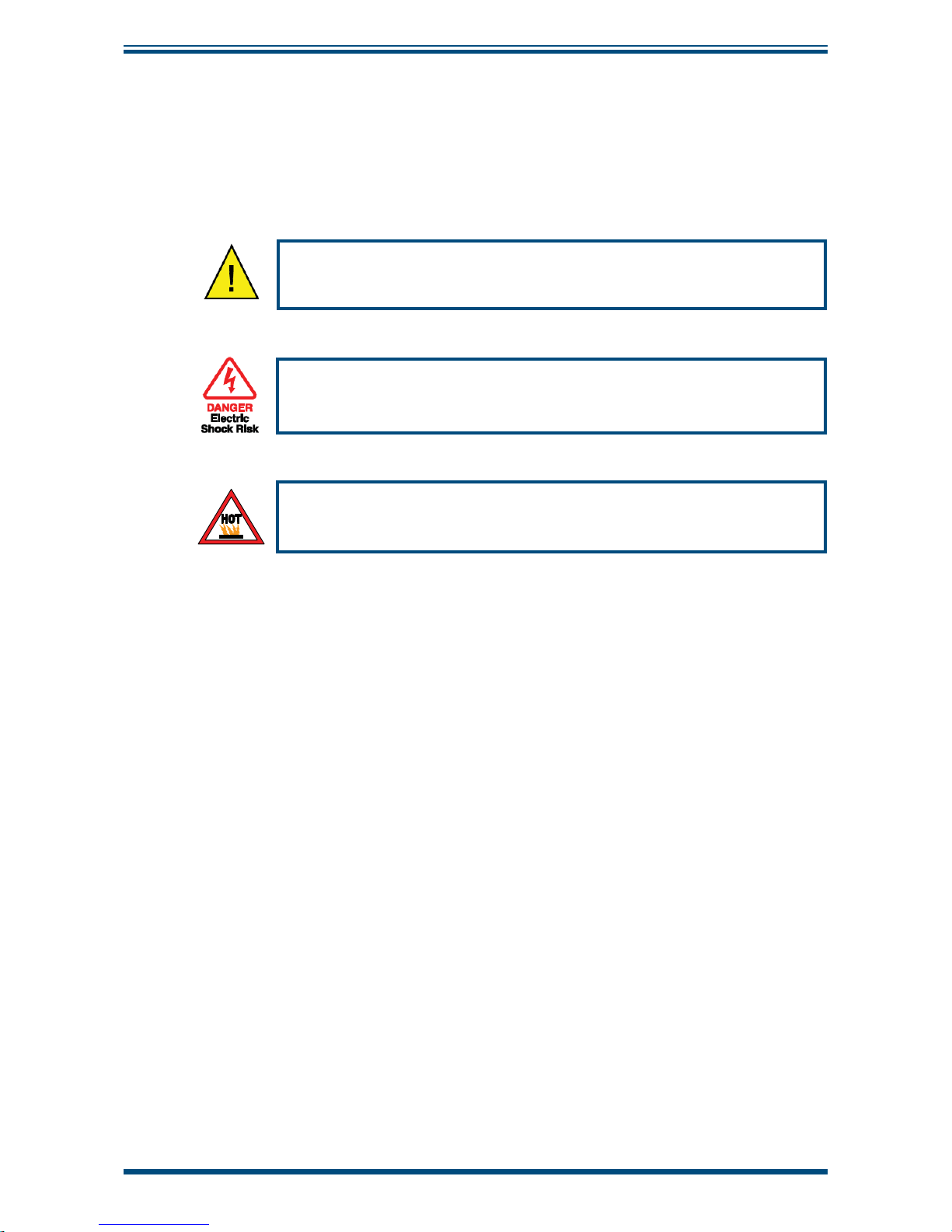
Where this hazard warning symbol appears in the following
sections, it is used to indicate areas where potentially hazardous
operations need to be carried out.
Where this symbol appears in the following sections it is used to
indicate areas of potential risk of electrical shock.
Where this hot surface warning appears in the
following sections it is used to indicate areas where
the surface may potentially be dangerously hot.
Page 11

XZR400 Series User’s Manual
Michell Instruments 1
INTRODUCTION
1 INTRODUCTION
The XZR400 Series Trace Oxygen Analyzer is designed to measure oxygen as an inpurity
in nitrogen, carbon dioxide, argon, helium or other inert gases. Analysis is both quick
and stable, utilizing our metallic sealed reference sensor (MSRS), with no requirement
for reference air.
There are 4 versions of the XZR400 analyzer. All are trace oxygen analyzers designed to
measure oxygen content in gas, between 0.01 ppm and 25% O2 (250,000 ppm).
Michell Instruments can supply the analyzer so that it is suitable for use with enriched
oxygen samples, including pure oxygen which may accidentally be introduced to the
sample. This cleaning service must be ordered at the time of purchase as special
components are required.
Extended operating ranges of 0 to 30% or 0 to 50% O2 can be supplied but will require
the analyzer to be cleaned for oxygen service.
Typical applications include:
Gas purity
Inerting or blanketing specifi c atmospheres
Combustion pre-mixing analysis
Respiratory or medical gas mixtures
Heat treatment
Four models of the XZR400 Series Oxygen Analyzer are available:
• A rack-mount model XZR400A1 (XZR-400-RM)
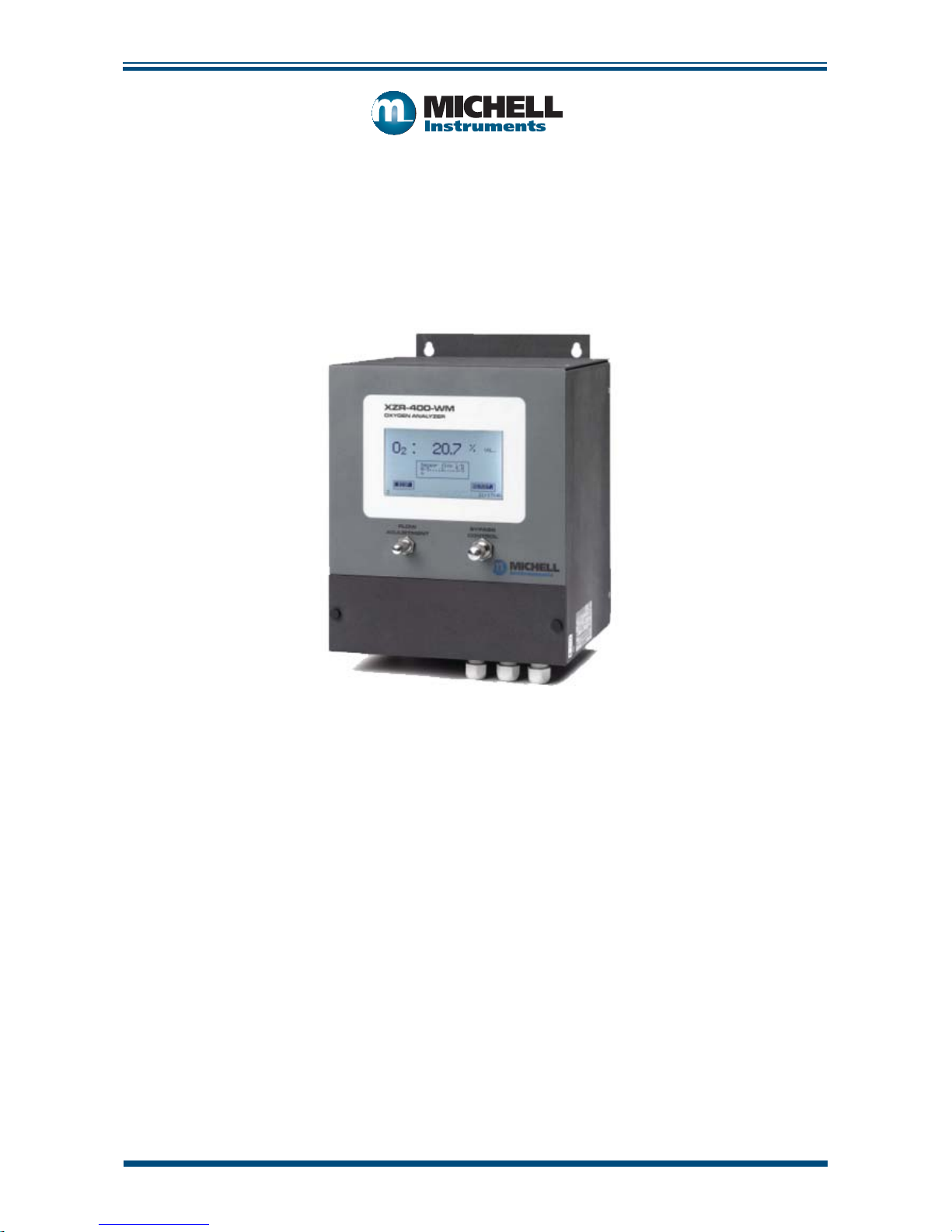
• A wall-mount model XZR400A2 (XZR-400-WM)
• A bench-mount model XZR400A3 (XZR-400-BM)
• A transportable model XZR400A4 (XZR-400-TP)
NOTE: The rack-mount version can be supplied with a built-in Easidew
sensor for measuring moisture in the range -100 to +20 °C
Sample gases at pressures up to a maximum of 2 barg (29 psig) can be accepted.
Page 12

XZR400 Series User’s Manual
2 97472 Issue 3, August 2018
INTRODUCTION
The XZR400 Series includes the following front panel mounted items:
• Liquid crystal touchscreen display
• Flow adjustment valve
• Bypass control valve
1.1 Operating Principle
The analyzer operates on the zirconium oxide (zirconia) principle.
A sample of the gas to be measured is connected to the inlet port of the analyzer. The
sample gas fl ows through stainless steel pipework into the oven where the zirconia
oxygen sensor is located.
The sample fl ow should be set to between 1 and 3 l/hr using the electronic fl owmeter,
and sample and bypass needle valves on the front of the unit.
The sample gas circulates in the oven, which is heated to temperatures above 600°C,
necessary for the zirconia oxygen sensor to operate properly.
The Michell Metallic Sealed Reference Sensor (MSRS) generates a signal that is
proportional to the logarithm of the ratio of the oxygen partial pressure in the sample
to the oxygen partial pressure contained on the sealed reference side of the MSRS.
The analyzer provides the O2 concentration on the screen and via the 4-20 mA output
(optional on XZR400A3).
The optional Easidew Transmitter utilizes ceramic impeadance technology and further
details can be found on our website.
Page 13
XZR400 Series User’s Manual
Michell Instruments 3
INTRODUCTION
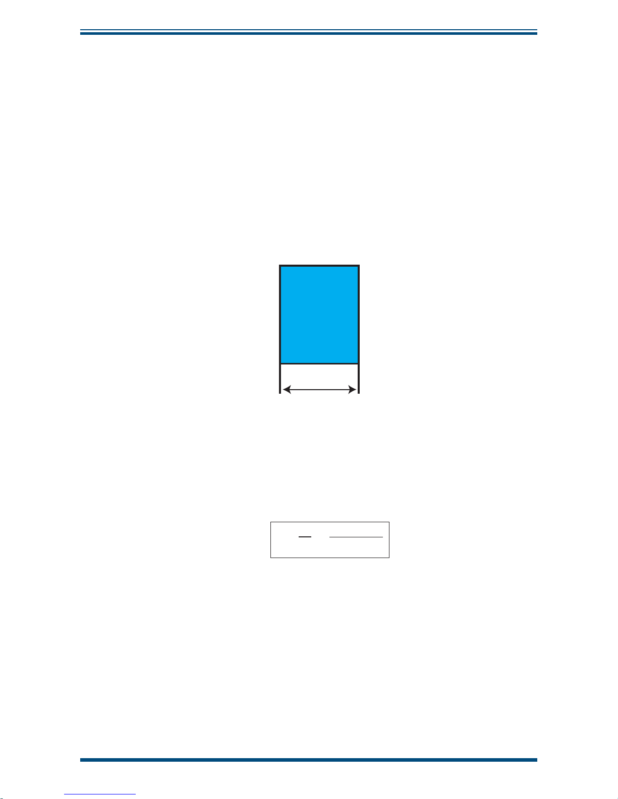
1.2 The MSRS Technology
The zirconium oxide sensors are often referred to as the ‘high temperature’
electrochemical sensors. The principle is based on the Nernst principle [W. H. Nernst
(1864-1941)]. Zirconium oxide sensors use a solid state electrolyte and are stabilized
with yttrium oxide. The zirconium oxide probe is plated on opposing sides with platinum
which serves as the sensor electrodes. For a zirconium oxide sensor to operate properly,
it must be heated to approximately 600°C. At this temperature, on a molecular basis,
the zirconia lattice becomes porous, allowing the movement of oxygen ions from a
higher concentration of oxygen to a lower one, based on the partial pressure of oxygen.
The movement of oxygen ions across the zirconium oxide produces a voltage between
the two electrodes, the magnitude of which is based on the oxygen partial pressure
differential created by the reference and sample gas.
(T)
Zirconia
P
P
ref.
P
P
meas.
E
Figure 1
Zirconia Sensor Operating Principle
Within the oven the zirconium oxide MSRS is maintained at a temperature of 634°C.
The MSRS generates a signal that is proportional to the natural logarithm of the partial
pressure of oxygen p (O2).
E =
RT
4F
p (O
2
ref)
p (O
2
meas)
ln
With a known reference electrode and a constant temperature it is possible to defi ne
the partial pressure of oxygen using the Nernst-equation (see above).
The conductivity of zirconium oxide increases exponentially with temperature. The oxide
ion conductivity is optimized at temperatures above 600°C.
The MSRS technology allows the design of miniaturized zirconium oxide-based oxygen
sensors. The low mass and volume of the MSRS sensors have a positive effect on the
response time, which is one of the best available on the market.
Page 14
XZR400 Series User’s Manual
4 97472 Issue 3, August 2018
INTRODUCTION
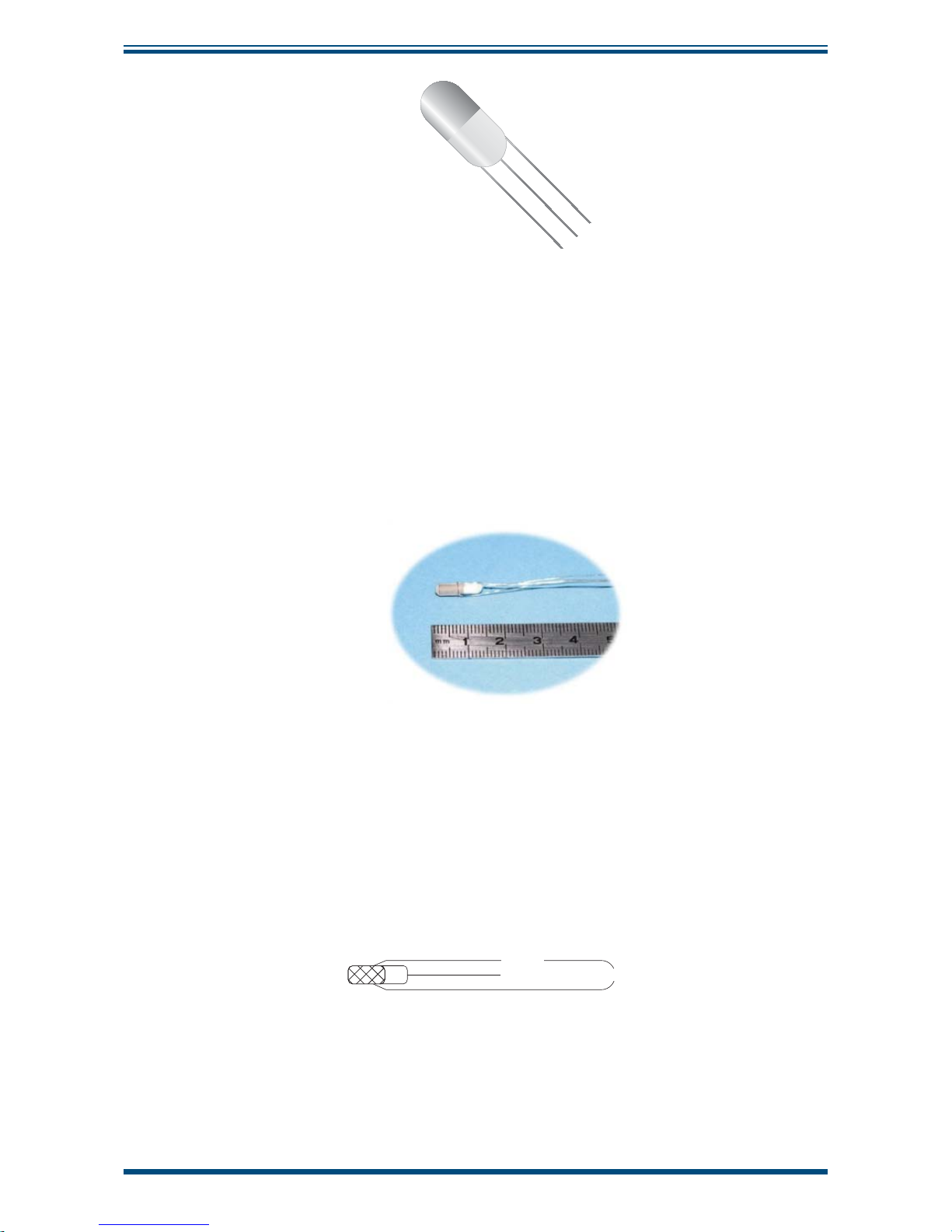
Figure 2
MSRS Sensor
Conventional zirconium oxide sensors require an air reference on one side of the sensor
with the sample on the other. This provides a known constant on one side. The Michell
MSRS does not require an air reference but instead utilizes a metal, and its oxide,
sealed in the zirconium sheath. This allows the sensor operation to be irrespective of
the ambient air quality and negates the requirement for a ‘zero’ calibration gas.
Figure 3
MSRS Dimensions
Temperature is a major component in the Nernst equation and can affect the accuracy
of some sensors. Placing the thermocouple in contact with the small sensor body helps
provide a very accurate temperature measurement. The complete design offers high
accuracy and repeatability.
02 Meas.
0
2
Ref. S Thermocouple
Figure 4
MSRS Wiring
Page 15
XZR400 Series User’s Manual
Michell Instruments 5
INTRODUCTION
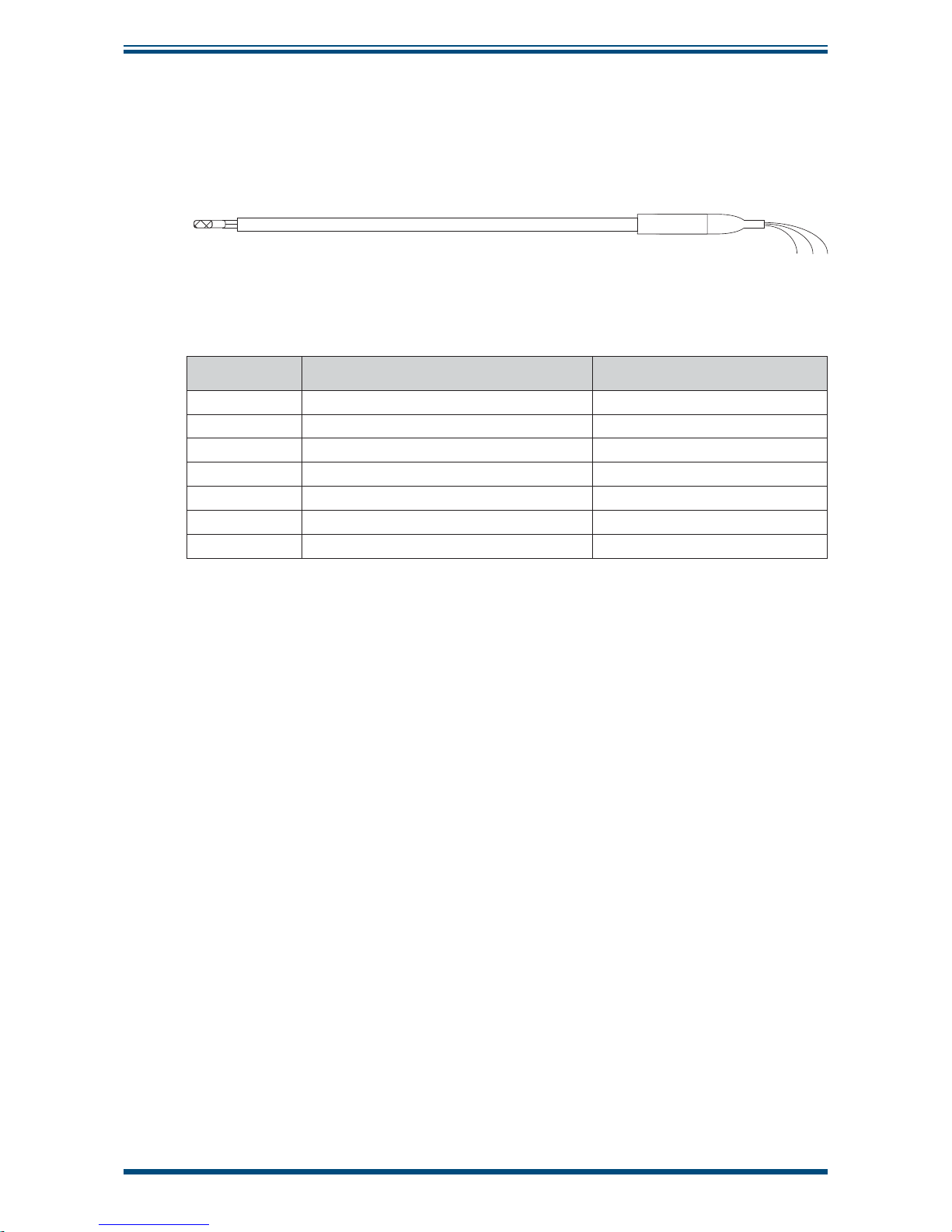
Figure 5
shows the MSRS and its S thermocouple installed in a 4-hole aluminum tube.
This confi guration has the part number XZR400-SMP. Any reference to the MSRS sensor
refers to this complete assembly which is considered solid state and non user-serviceable.
4
567
1
2
3
Figure 5
XZR400 Series MSRS Assembly
Item Description Wiring
1 MSRS
2 S-type thermocouple
3 4-hole alumina tube
4 Stainless steel connector
5O
2
reference wire blue wire
6 Common (O
2
meas. & - TC) white wire
7 Positive thermocouple (+TC) orange wire
Table 1 XZR400 Series MSRS Assembly
Page 16

XZR400 Series User’s Manual
6 97472 Issue 3, August 2018
INSTALLATION
2 INSTALLATION
It is essential that the installation of the electrical and gas
supplies to this analyzer be undertaken by qualifi ed personnel.
2.1 Unpacking the Analyzer
Open the box and unpack carefully as follows. Save all the packing materials for the
purpose of returning the instrument for any warranty claims.
1. Remove the accessories (if ordered with the analyzer). If no accessories
have been ordered the box should contain the following items:
• XZR400 Series Oxygen Analyzer
• Power cable (except XZR400A2 model)
• User’s Manual
• Test result sheet
2. Remove the documentation and packing material.
3. Remove the analyzer and power cable.
2.2 Preparation
Carefully read the following guidelines before installing the analyzer. If you are not sure
about the installation conditions and other important factors please contact a Michell
Instruments’ Application Engineer or a Michell Instruments’ representative prior to the
installation.
The following list will help you to identify the recommended preparation steps:
• The analyzer should be installed at ambient temperatures between 0 and
+55°C (32 to +131°F).
• The location of the installation should allow access to the display.
• The location of the installation should not expose the analyzer to any
vibration.
• The cables should not be exposed to extreme temperatures and mechanical
strain.
Page 17
XZR400 Series User’s Manual
Michell Instruments 7
INSTALLATION
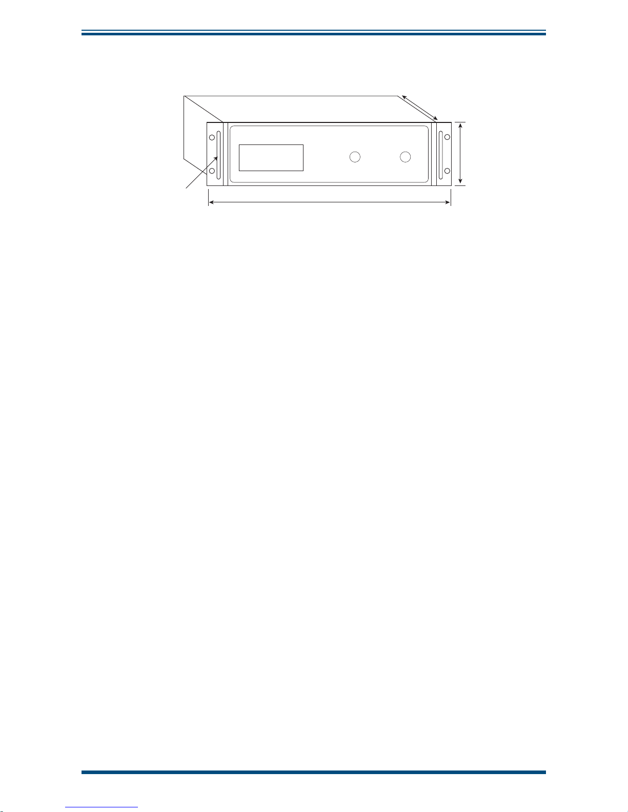
2.3 Dimensions - XZR400A1
483mm
(
19”
)
362mm + 50mm for cable clearance
(14.25” + 1.96”)
3U
132mm
(5.2”)
XZR-400-RM
OXYGEN ANALYZER
Handles protrude
40mm (1.6”)
FLOW
ADJUSTMENT
BYPASS
Figure 6
Dimensions - XZR400A1
2.3.1 Installing the XZR400A1
Choose your installation site carefully following the recommendations above. Once
installed into the rack, there should be at least 2U clearance spaces from other equipment
above and below the instrument.
To install, follow the steps below:
1. If necessary, remove any covers from the rack cabinet to gain access to
the rear and side.
2. Slide the instrument into the rack and support its weight while the four
fi xing screws are inserted.
3. Ensure that the front panel of the instrument is fl ush and square with the
front of the rack and tighten the fi xing screws.
Page 18
XZR400 Series User’s Manual
8 97472 Issue 3, August 2018
INSTALLATION
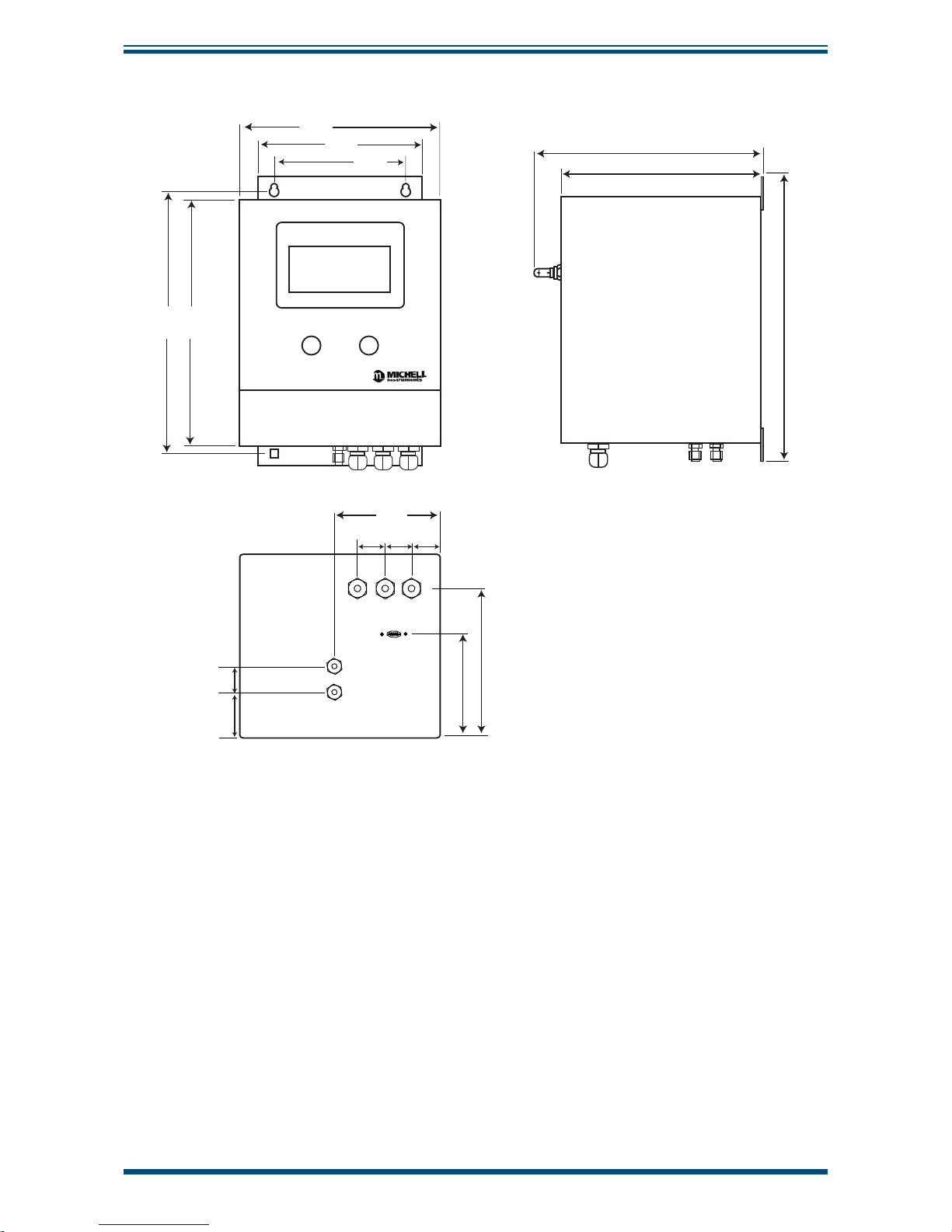
2.4 Dimensions - XZR400A2
274mm
(10.79”)
260mm
(10.24”)
220mm
(8.66”)
180mm
(7.09”)
152mm
(5.98”)
109mm
(4.29”)
172mm
(6.77”)
110mm
(4.33”)
30mm
(1.18“)
30mm
(1.18”)
30mm
(1.18”)
201mm
(7.91”)
236mm
(9.29”)
305mm
(12.01”
42mm
30mm
FLOW
ADJUSTMENT
BYPASS
CONTROL
GAS IN
GAS OUT
(1.18”)
(1.65”)
Figure 7
Dimensions - XZR400A2
Page 19
XZR400 Series User’s Manual
Michell Instruments 9
INSTALLATION
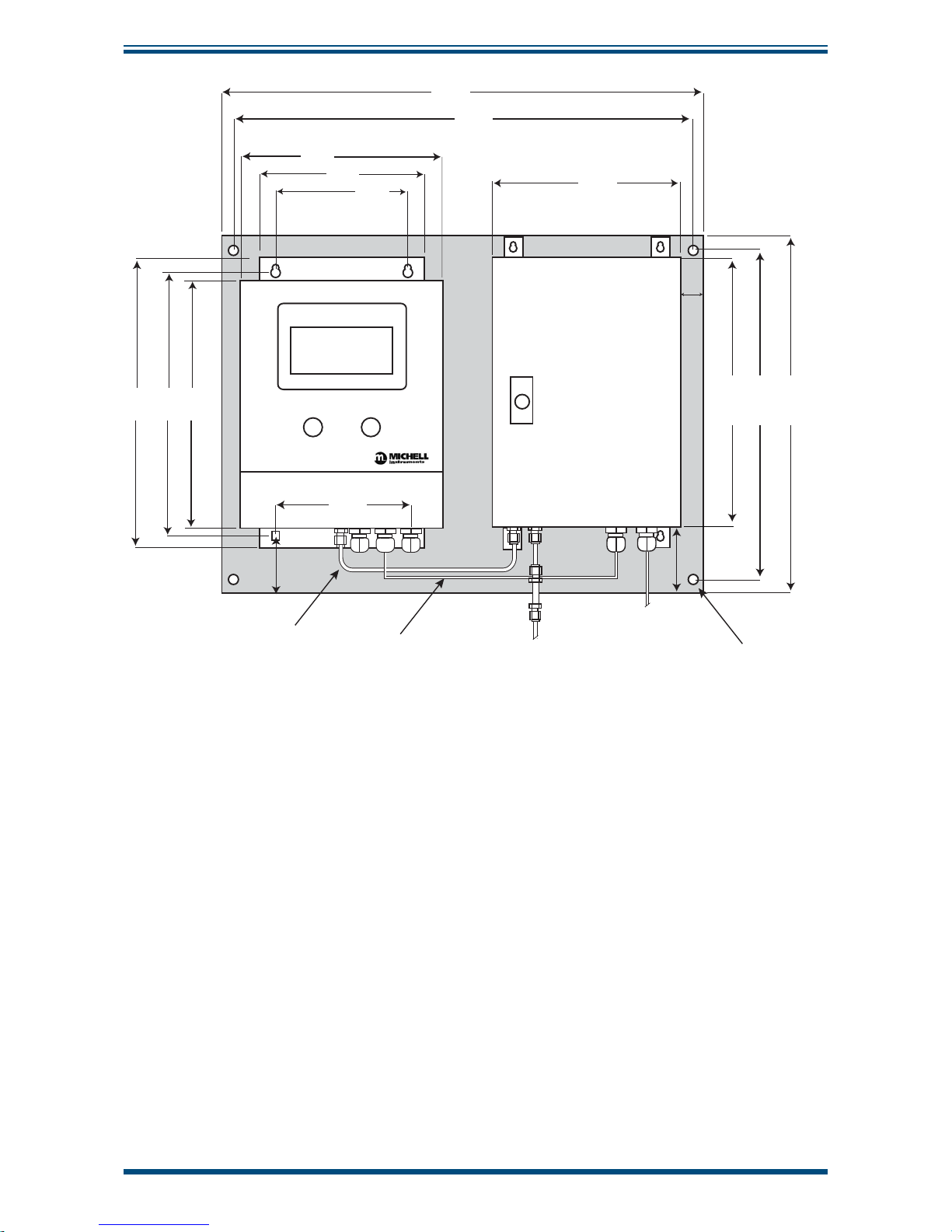
274mm
(10.79”)
260mm
(10.24”)
220mm
(8.66”)
180mm
(7.09”)
152mm
(5.98”)
201mm
(7.91”)
20mm
(.79”)
60mm
(2.4”)
490mm
(19.29”)
305mm
(12.01”)
370mm
(14.57”)
390mm
(15.35”)
FLOW
ADJUSTMENT
BYPASS
CONTROL
470mm
(18.50”)
305mm
(12”)
53mm
(2.09”)
6mm (0.24”) tube
Analyzer power supply
Particulate
filter
Gas Inlet
6mm
4 x Ø 8.4
230 V AC
50 Hz
470mm
(18.50”)
Figure 8
Dimensions - XZR400A2 with External Pump Option
2.4.1 Installing the XZR400A2
Choose your installation site carefully following the recommendations above.
Follow the steps below:
1. Identify a clean and fl at surface on a wall or other vertical location e.g.
an instrument panel that is suitable to hold the analyzer.
2. Prepare the mounting site by drilling 4 holes in appropriate locations
corresponding to the dimension and location of the fastening holes at the
back of the analyzer enclosure.
3. Fix the analyzer vertically to the installation surface using suitable screws.
The gas connections and the electrical connections should be on the
bottom.
Page 20

XZR400 Series User’s Manual
10 97472 Issue 3, August 2018
INSTALLATION
2.5 Dimensions - XZR400A3
220mm
(8.6”)
290mm
(11.4”)
260mm
(10.2”)
203mm
(7.9”)
236mm
(9.3”)
Figure 9
Dimensions - XZR400A3
2.6 Dimensions - XZR400A4
420mm
(16.5”)
450mm
(17.7”)
300mm
(11.8”)
350mm
(13.8”)
Figure 10
Dimensions - XZR400A4
Page 21
XZR400 Series User’s Manual
Michell Instruments 11
INSTALLATION
2.7 Operating Requirements
2.7.1 Environmental Requirements
The XZR400 Series should be installed in a clean, dust free environment. The
recommended ambient temperature is +20 to +25°C (+68 to +77°F) although the
instrument will operate, within specifi cation, inside the temperature band of 0 to +55°C
(32 to +131°F). It must be installed indoors in a non-condensing atmosphere.
2.7.2 Electrical Requirements
The analyzer requires the following electrical supply:
90 to 264 V AC, 47/63 Hz
There are 2 concentration alarm relays. The output contacts are normally open and
potential free. The relay switching capability is 10 W max (up to 100 V or up to 0.5 A).
2.7.3 Gas Requirements
To ensure that the sample gas is properly conditioned a
sampling system might be required.
Contact Michell Instruments if you wish to order a suitable
sampling system.
The gas must be clean, dry and oil mist free with the pressure up to a maximum of 2
barg (29 psig) and with particle size < 3 m.
The analyzer is not suitable for samples with hydrocarbons
present. These will combust on the cell and consume oxygen
molecules.
2.7.4 Sampling System
Depending upon the application a sampling system may be used to cope with high
pressure samples, samples with contamination or outdoor installations. The sampling
system may include components such as fi lters, pressure gauges, by-pass loops,
calibration inlet, pressure regulators and sample pumps - all installed on a panel, or in
an enclosure.
It is recommended that a stainless steel construction is used for all parts that will be in
contact with the gas.
Please consult Michell Instruments if a sampling system is required. Install the sampling
system as close as possible to the XZR400 Series analyzer to ensure the best possible
measurement results.
NOTE: Michell Instruments can provide a suitable sampling system when
delivering the analyzer. Contact a Michell Instruments’ Application Engineer
for more information.
Page 22
XZR400 Series User’s Manual
12 97472 Issue 3, August 2018
INSTALLATION
2.8 Connections to the XZR400A1
2.8.1 Front Panel
ABC
Item Description
A Touchscreen LCD
B Flow adjustment needle valve
C Bypass control needle valve
Figure 11
Front Panel XZR400A1
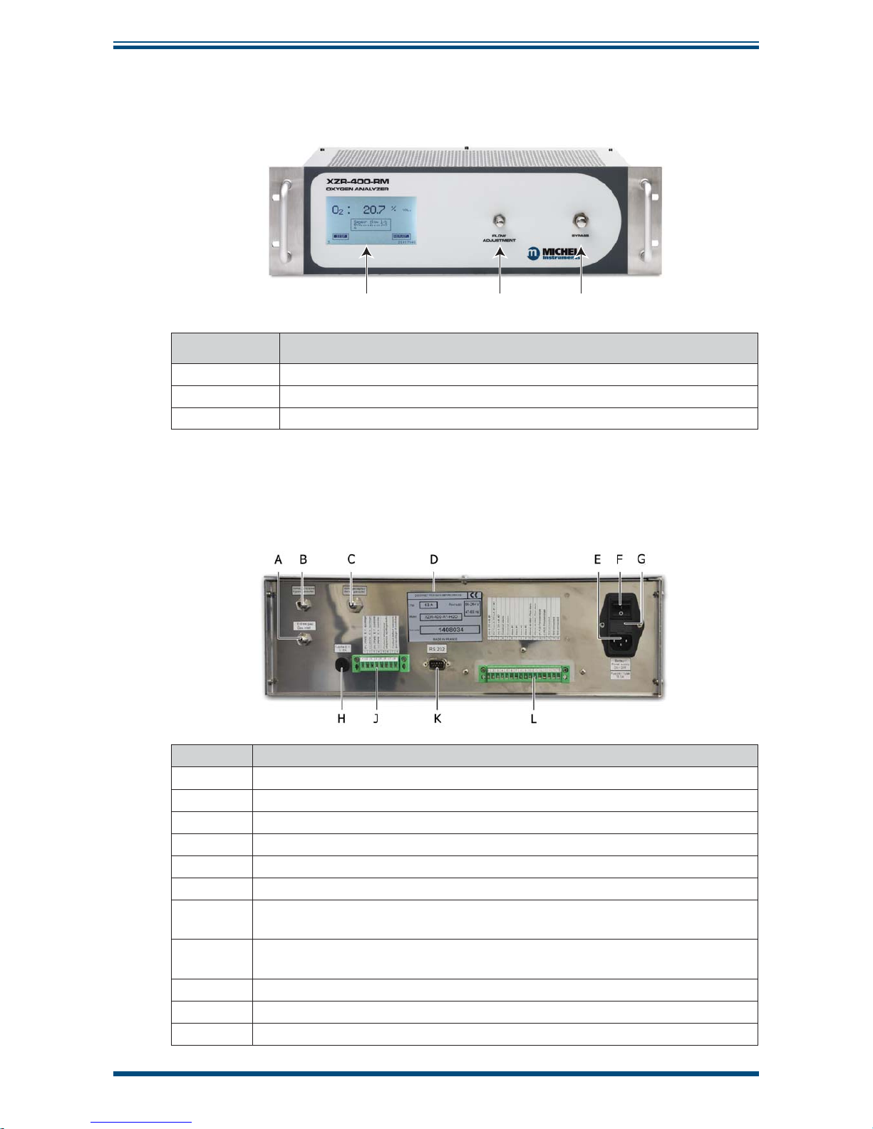
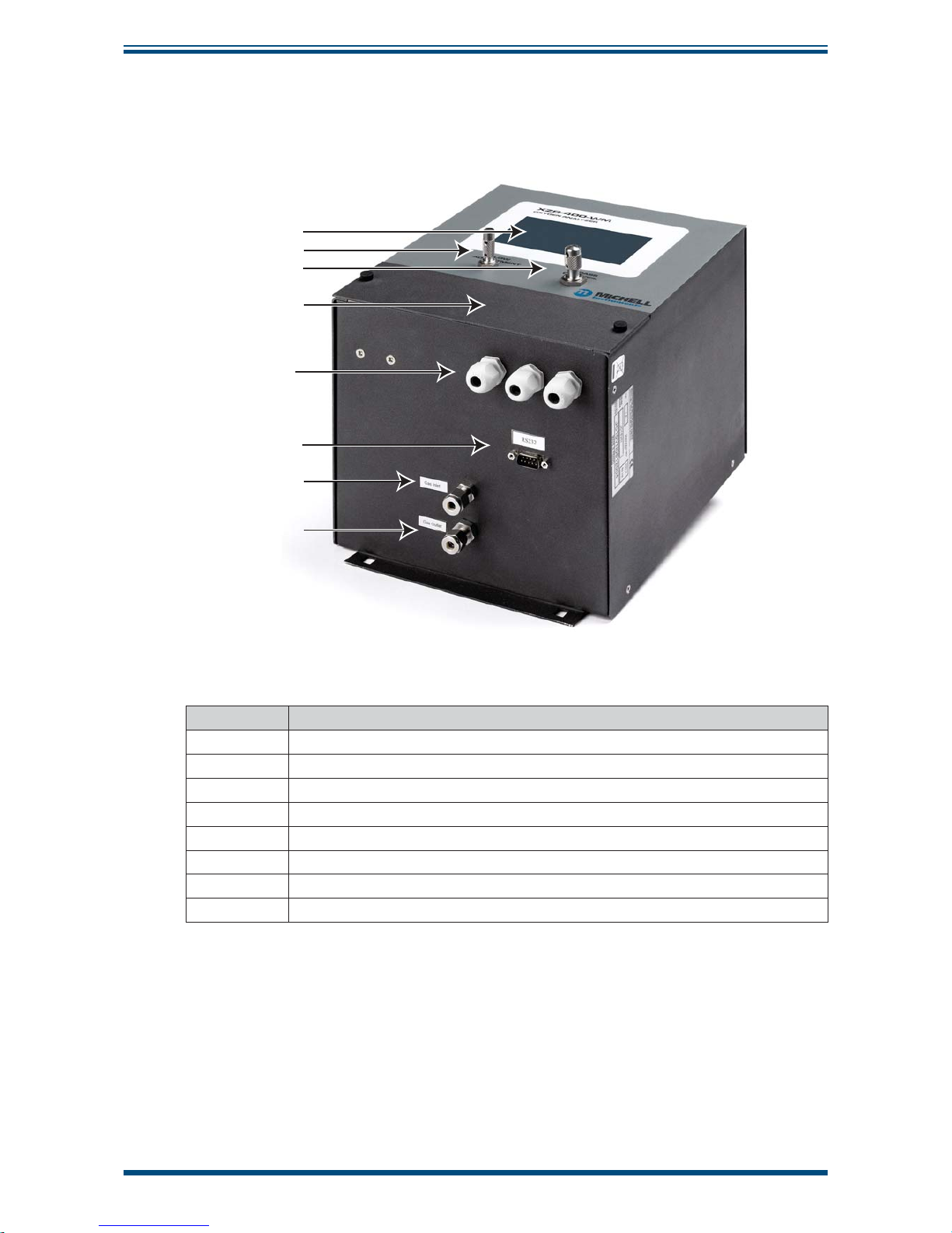
2.8.2 Back Panel
An electrical connection terminal is provided for signal and alarm connections.
Item Description
A Inlet fi tting for gas sample to be analyzed.
B Outlet fi tting for gas sample output bypass.
C Outlet fi tting for gas sample to be analyzed.
D Manufacturer's plate.
E Mains socket (90-132 / 187-264 V AC, 47/63 Hz).
F On/Off button.
G Housing for analyzer's 2 x electrical protection fuses
(250 V AC, 6.3 A)
H Housing for solenoid valve's electrical protection fuses (250 V AC, 3.15 A).
Only fi tted on the rack with automatic setting option.
J Optional connector for the automatic setting option.
K Optional D-sub DE9 male plug (RS232 port).
L Electrical connector.
Figure 12
Back Panel XZR400A1
Page 23
XZR400 Series User’s Manual
Michell Instruments 13
INSTALLATION
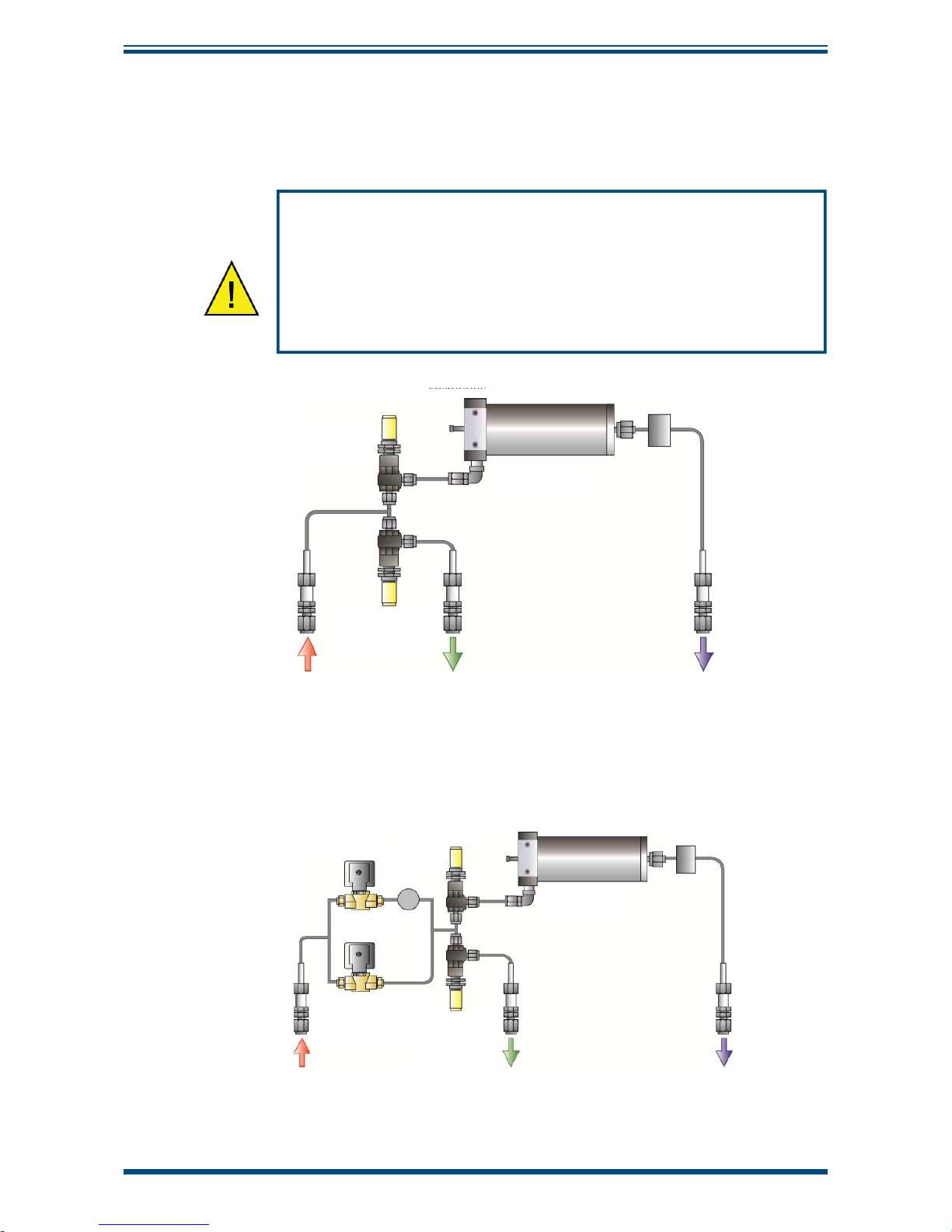
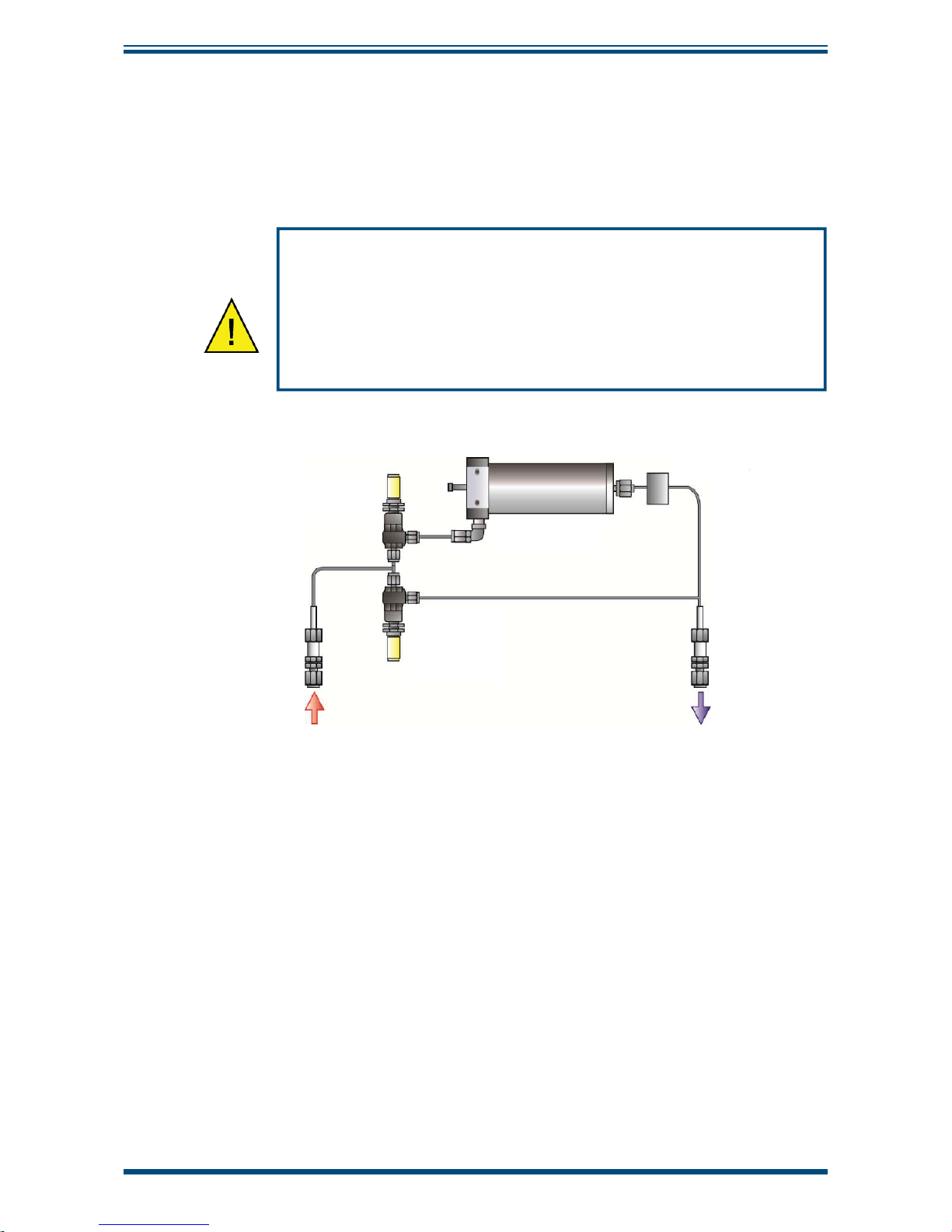
2.8.3 Gas Inlet, Outlet and Bypass Gas Connections
The fl uidic system comprises 2 fl ow control valves (sensor fl ow and by-pass fl ow), an
electronic fl ow meter and a sensor. The gas connections are stainless steel Swagelok
1/8" quick connecting couplers, which guarantee a perfect seal and easy removal.
The evacuation of the analyzed sample must be carried out at
atmospheric pressure, otherwise the total pressure adjustment
option is required.
The measurement of hazardous gas samples require the
analyzer's outlet to be outside the analysis area and must be in
accordance with local regulations.
Sensor flow
adjustment
Sensor
Electronic
flow meter
Gas outlet
bypass
sample
Analyzed
gas
outlet
Bypass flow
adjustment
Inlet for gas
to be
analyzed
Figure 13
Gas Circuit Diagram for Rack Version
Sensor flow
adjustment
Sensor
Pump
Electronic
flow meter
NO
Solenoid
valve
NC
Solenoid
valve
Gas outlet
bypass
sample
Analyzed
gas
outlet
Bypass flow
adjustment
Inlet for gas
to be
analyzed
Figure 14
Gas Circuit Diagram for Rack & Pump Version
Page 24
XZR400 Series User’s Manual
14 97472 Issue 3, August 2018
INSTALLATION
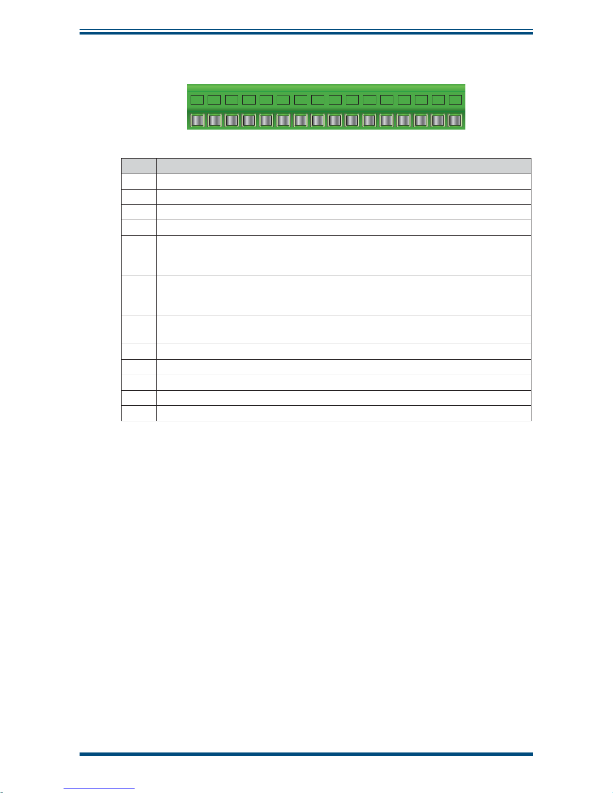
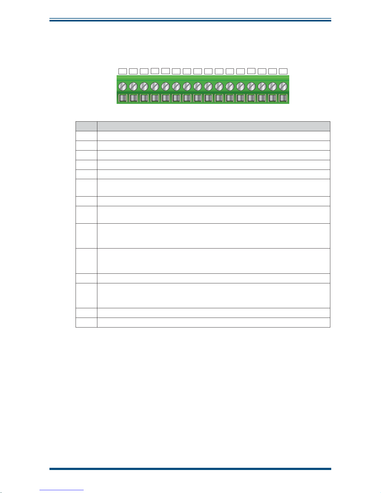
2.8.4 Electrical Terminal Block
1 2 3 4 5 6 7 8 9 10111213141516
Item Function
1 (+) 4-20 mA Output No 1. Measurement proportional to the chosen O
2
scale.
2 0 V from the 4-20 mA Output No 1 & 2.
3 (+) 4-20 mA Output No. 2. Measurement proportional to the chosen 0
2
scale.
4-5 General fault alarm dry contact (250 V AC, 2 A or 30 V DC, 2 A on resistive load.
6-7 Alarm No. 1 dry contact terminal (250 V AC, 2 A or 30 V DC, 2 A resistive load).
Function mode (positive, normal) and hysteresis can be confi gured by setting the
parameters.
8-9 Alarm No. 2 dry contact terminal (250 V AC, 2A or 30 V DC, 2A resistive load).
Function mode (positive, normal) and hysteresis can be confi gured by setting the
parameters.
10-11 Dry contact terminal for fl ow alarm option (250 V AC, 2 A or 30 V DC, 2 A on
resistive load).
12 (+) 4-20 mA input. Option process pressure correction input.
13 (0V) 4-20 mA input. Option process pressure correction input.
14 RS485 Data +/A.
15 RS485 Data -/B.
16 RS485 0 V.
Figure 15
Electrical Terminal Block XZR400A1
2.8.5 D-Sub DE9 plug
This optional D-Sub DE9 type male plug (9 pin) is used to connect an RS232 port.
2.8.6 Pluggable 8 pins electrical connector
This optional connector allows the connection of terminals for automatic analyzer
calibration.
Page 25
XZR400 Series User’s Manual
Michell Instruments 15
INSTALLATION
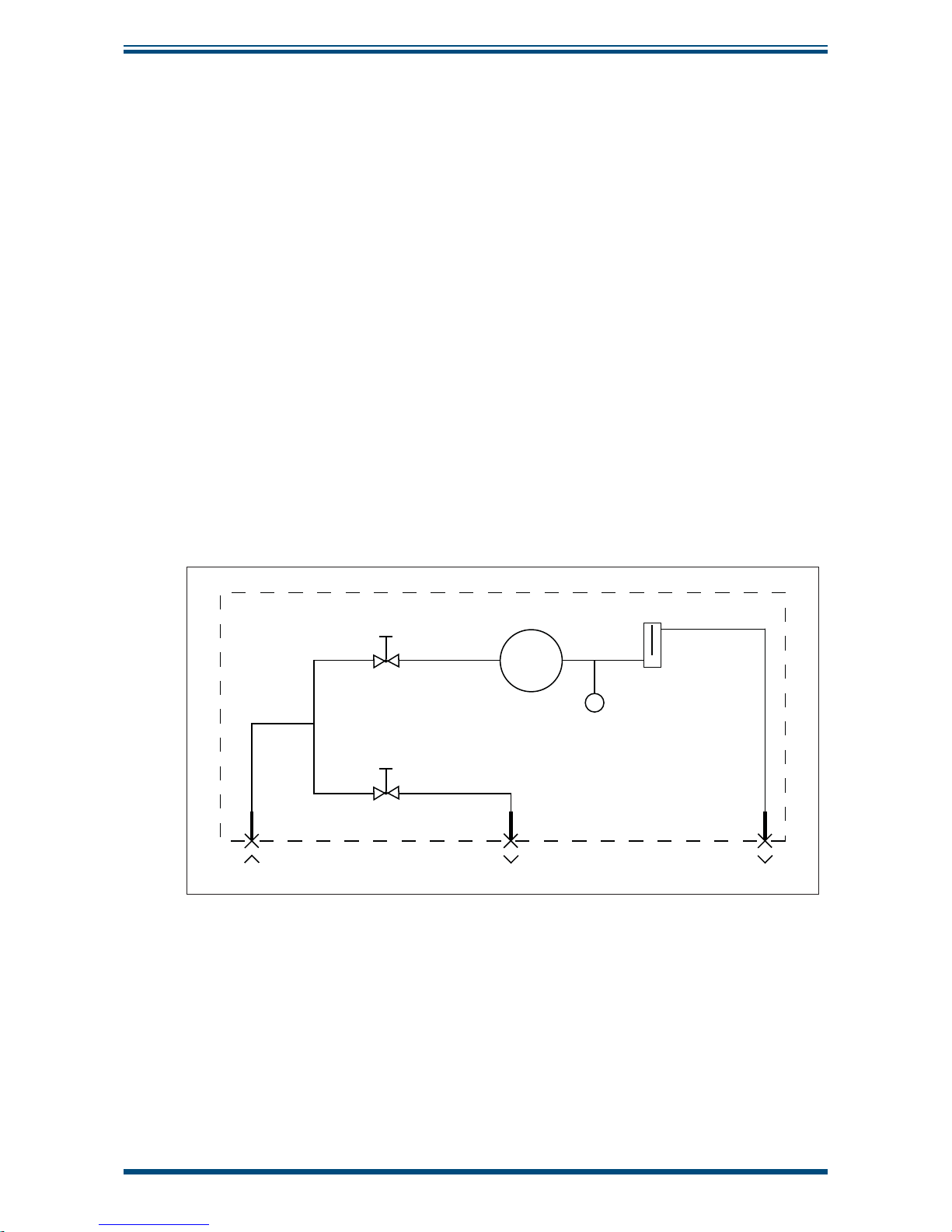
2.8.7 Sample Path
The MSRS sensor is placed inside an oven in which the gases to be analyzed are
circulated. The oven consists of a gas inlet head and a outlet plate. 3 Viton O-rings
ensure the sealing of this device (2 for the inlet and 1 for the outlet).
The internal sample path consists of:
• 2 fl ow control valves: sensor fl ow and by-pass fl ow
• 1 sealing head
• 1 outlet plate
• 1 oven tube
• 1 electronic fl ow meter
• 1 MSRS sensor
• 3 Swagelok 6mm stainless steel bulkhead unions (1 gas inlet and 2
gas outlets) - on the rear panel
XZR400A1
Sensor flow adjustment valve
O2 sensor
By-pass flow adjustment valve
Barometric pressure sensor
Ɨ” bulkhead union Ɨ” bulkhead unionƗ” bulkhead union
Sampling gas inlet
Electronic flowmeter 0-12 l/h
Sampling gas outletSampling gas outlet
Figure 16
Sample Path XZR400A1
Page 26
XZR400 Series User’s Manual
16 97472 Issue 3, August 2018
INSTALLATION
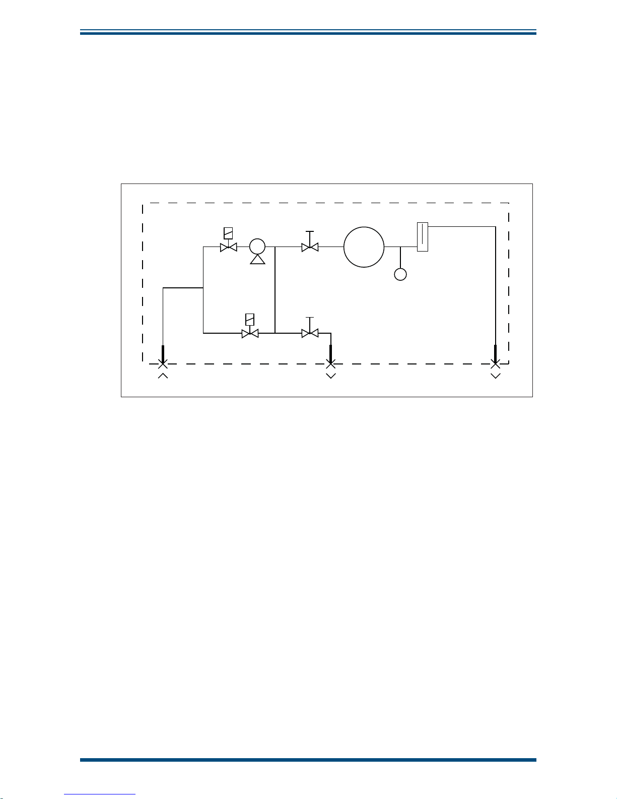
XZR400A1 WITH INTERNAL PUMP:
• 3 Swagelok 6mm stainless steel bulkhead unions (1 gas inlet and 2
gas outlets) - on the rear panel
• 1 sampling pump (3 l/min)
• 2 electrovalves
XZR400A1
Sensor flow adjustment valve
O2 sensor
By-pass flow adjustment valve
Barometric pressure sensor
Ɨ” bulkhead union Ɨ” bulkhead unionƗ” bulkhead union
Sampling gas inlet
Electronic flowmeter 0-12 l/h
Sampling gas outletSampling gas outlet
P
N.O. Solenoid valve
N.C. Solenoid valve
Sampling pump
Figure 17
Sample Path with Pump Fitted XZR400A1
Page 27

XZR400 Series User’s Manual
Michell Instruments 17
INSTALLATION
2.8.7.1 Signal Processing Path
The values of oxygen concentration and fl ow passing through the sensor are displayed
continuously.
On specifi c screen pages the following control parameters are displayed:
• Oven temperature
• Ambient temperature (corresponding to the thermocouple junction
temperature)
• O
2
concentration
• MSRS sensor voltage
• Barometric pressure (standard) or process pressure (optional)
• Flow passing through the sensor
Analog Outputs:
• 2 x 4-20 mA analog outputs proportional to user-defi ned scales. The
wiring connector is on the rear side
Standard Alarms:
• General fault alarm
• 2 concentration alarms with user-confi gurable high/low thresholds and
hysteresis
Optional Alarm:
• An optional fl ow alarm is available
Page 28
XZR400 Series User’s Manual
18 97472 Issue 3, August 2018
INSTALLATION
2.9 Connections to the XZR400A2
The connections are shown below.
A
B
C
D
E
F
G
H
Item Description
A Graphic touch screen - displays measurement and menus.
B Multi-turn knurled knob for fi ne adjustment of the gas fl ow.
C Multi-turn knurled knob for basic adjustment of the gas fl ow (bypass).
D Removable plate for access to electrical terminal block and mains fuse.
E Three cable glands are provided for the electrical connections.
F Optional D-Sub DE9 male plug (RS485 or RS232 port).
G Inlet fi tting for the gas sample to be analyzed (for 6mm tube).
H Outlet fi tting for the analyzed gas sample (for 6mm tube).
Figure 18
Connections XZR400A2
Page 29
XZR400 Series User’s Manual
Michell Instruments 19
INSTALLATION
2.9.1 Gas Sample Inlet and Outlet Fittings
The gas path consists of 2 fl ow control valves (sensor fl ow and by-pass fl ow), a sensor
and an electronic fl owmeter. For the gas inlet and the outlet connections, Swagelok
stainless steel 6mm bulkhead unions are used, which guarantees perfect sealing and
easy removal.
The evacuation of the analyzed sample must be carried out at
atmospheric pressure, otherwise the total pressure adjustment
option is required.
The measurement of hazardous gas samples require the
analyzer's outlet to be outside the analysis area and must be in
accordance with local regulations.
Sensor flow
adjustment
Bypass flow
adjustment
Inlet for gas
to be
analyzed
Analyzed
gas
outlet
Sensor
Electronic
flow meter
Figure 19
Gas Circuit Diagram for XZR400A2
Page 30
XZR400 Series User’s Manual
20 97472 Issue 3, August 2018
INSTALLATION
2.9.2 Electrical Terminal Block
The terminal block is located by removing the front panel cover.
1 2 3 4 5 6 7 8 9 10111213141516
Item Function
1 Connection to the MSRS cell; system reserved (TC+ – orange).
2 Connection to the MSRS cell; system reserved (common – white).
3 Connection to the MSRS cell; system reserved (reference – blue).
4 Oven connection, system reserved.
5 Oven connection, system reserved (see paragraph 15.2).
6 (+) 4-20 mA output measurement proportional to the chosen O
2
scale. A second
4-20 mA output is available as an option.
7 4-20 mA (0 V).
8-9 Optional. Dry contact alarm for fl ow rate setting (250 V AC, 30 V DC or 2 A, 2 A
resistive load). Direction of action.
10-11 Threshold alarm No. 1 dry contact terminal (250 V AC , 2 A or 30 V DC, 2 A on
resistive load). Function mode (positive, normal) and hysteresis can be confi gured
by setting the parameters.
12 Threshold alarm No. 1 dry contact terminal (250 V AC , 2 A or 30 V DC, 2 A on
resistive load). Function mode (positive, normal) and hysteresis can be confi gured
by setting the parameters.
13 Shared contact for alarms No.1 and No. 2.
14 Threshold alarm No. 2 dry contact terminal (250 VAC , 5A or 30 VDC, 5A on
resistive load). Function mode (positive, normal) and hysteresis can be confi gured
by setting the parameters.
15 Mains supply phase.
16 Mains supply neutral.
The equipment is protected by a T2 A - 250 V AC timed fuse (5 x 20 mm) located near
the terminal block
Figure 20
Electrical Terminal Block XZR400A2
2.9.3 D-Sub DE9 plug
This optional D-Sub DE9 type male plug (9 pin) is used to connect an RS485 or RS232
port.
Page 31

XZR400 Series User’s Manual
Michell Instruments 21
INSTALLATION
2.9.4 D-Sub DA15 plug
This optional D-Sub DA15 male plug (15 pin) is used to connect a second 4-20 mA
output, a total pressure adjustment inlet, and the analyzer's auto adjustment terminals,
as well as automatic scale switching operations.
2.9.5 Sample Path
The MSRS sensor is placed inside an oven in which the gases to be analyzed are
circulated. The oven consists of a gas inlet head and a outlet plate. 3 Viton O-rings
ensure the sealing of this device (2 for the inlet and 1 for the outlet).
The internal sample path consists of:
• 2 fl ow control valves: sensor fl ow and by-pass fl ow
• 1 sealing head
• 1 outlet plate
• 1 oven tube
• 1 electronic fl ow meter
• 1 MSRS sensor
• 2 Swagelok 6mm stainless steel bulkhead unions (gases inlet and outlet)
- under the analyzer
XZR400A2
Sensor flow adjustment valve
O2 sensor
By-pass flow adjustment valve
Barometric pressure sensor
6mm bulkhead union 6mm bulkhead union
Sampling gas inlet
Sampling gas outlet
Electronic flowmeter 0-12 l/h
Figure 21
XZR400A2 Sample Path
Page 32

XZR400 Series User’s Manual
22 97472 Issue 3, August 2018
INSTALLATION
2.9.6 Signal Processing Path
The values of oxygen concentration and fl ow passing through the sensor are displayed
continuously.
On specifi c screen pages the following control parameters are displayed:
• Oven temperature
• Ambient temperature (corresponding to the thermocouple junction
temperature)
• O
2
concentration
• MSRS sensor voltage
• Barometric pressure (standard) or process pressure (optional)
• Flow passing through the sensor
Analog Outputs:
The analog output can be confi gured to represent the measured oxygen parameters and
is provided as a 2-wire signal. It can be set-up as a current loop signal 4-20 mA. The
confi guration of the output can be set via the
Main Menu.
The analog output is proportional to user-defined scale. The connection is inside the
enclosure, behind the removable panel on the front of the unit. An optional second
4-20 mA output is available.
2.9.7 Alarm Outputs
Standard Alarms:
• general fault alarm
• 2 concentration alarms with user-confi gurable high/low thresholds and
hysteresis
Two alarm relays are provided. They are connected to the instrument via the terminal
block inside the XZR400A2 Analyzer.
Under the
Main Menu, the two concentration alarms can be set-up to operate when a
pre-set parameter threshold level is exceeded (refer to Section 3.6.2). The direction of
the activation, as well as the hysteresis can be confi gured.
The fault alarm is a non-confi gurable alarm which continuously monitors the status of
the analyzer. During normal operating conditions the alarm is off. The alarm will be
triggered and both relay contacts will open if:
• the oven temperature is low
• the thermocouple breaks
• a fault with the memory occurs
Optional Alarm:
• an optional fl ow alarm is available
Page 33

XZR400 Series User’s Manual
Michell Instruments 23
INSTALLATION
2.10 Connections to the XZR400A3
2.10.1 Front Panel
The front panel features are shown below:
A
B
C
D
E
Item Description
A Carrying handle.
B Multi-turn knurled knob for basic adjustment of the gas fl ow (bypass).
C Graphic touch screen - displays measurement and menus.
D Multi-turn knurled knob for fi ne adjustment of the gas fl ow.
E Access plate to the MSRS sensor.
Figure 22
Connections Front Panel - XZR400A3
Page 34

XZR400 Series User’s Manual
24 97472 Issue 3, August 2018
INSTALLATION
2.10.2 Side Panel
The side panel connections are shown below:
A
B
C
D
E
F
G
Item Description
A ON/OFF button.
B Mains socket (90-132/187-264 VA, automatic range switching, 47/63 Hz).
C Inlet fi tting for the gas sample to be analyzed (for 6mm tube).
D Manufacturer's plate.
E Optional Sub-D DE9 male connector; RS232 or RS485 output.
F Optional Sub-D DA15 male connector
G Outlet fi tting for the gas sample to be analyzed (for 6mm tube).
Figure 23
Connections Side Panel - XZR400A3
Page 35

XZR400 Series User’s Manual
Michell Instruments 25
INSTALLATION
2.10.3 Electrical Terminal Block
1 2 3 4 5 6 7 8 9 10111213141516
Item Function
1 Connection to the MSRS cell; system reserved (TC+ – orange).
2 Connection to the MSRS cell; system reserved (common – white).
3 Connection to the MSRS cell; system reserved (reference – blue).
4-5 Oven connection, system reserved.
6 Optional (+) 4-20 mA output. Measurement proportional to the chosen O
2
scale.
A second 4-20 mA output is available as an option.
7 Optional 4-20 mA (0 V).
8-9 Optional Dry contact alarm for fl ow rate setting (250 V AC, 30 V DC or 2 A, 2 A
resistive load). Direction of action (positive, normal).
10-11 Optional General alarm dry contact terminal (250 V AC, 2 A or 30 V DC, 2 A on
resistive load). Direction of action (positive, normal).
12 Optional Threshold alarm No. 1 dry contact terminal (250 V AC , 2 A or 30 V DC,
2 A on resistive load). Function mode (positive, normal) and hysteresis can be
confi gured by setting the parameters.
13 Optional Shared contact for alarms No.1 and No. 2.
14 Optional Threshold alarm No. 2 dry contact terminal (250 V AC, 5 A or 30 V DC,
5 A on resistive load). Function mode (positive, normal) and hysteresis can be
confi gured by setting the parameters.
15-16 Not connected.
Figure 24
Electrical Terminal Block XZR400A3
Page 36

XZR400 Series User’s Manual
26 97472 Issue 3, August 2018
INSTALLATION
2.11 Connections to the XZR400A4-Transportable
A
B
C
D
E
F
G
H
Item Description
A Graphic touch screen - displays measurement and menus.
B Multi-turn knurled knob for fi ne adjustment of the gas fl ow.
C Multi-turn knurled knob for basic adjustment of the gas fl ow (bypass).
D Mains socket (90 - 264 V AC, 47/63 Hz)
On/Off button.
Analyzer housing for 2 electrical protection fuses (250 V AC - T2A or 250 V
AC - T6.3A).
E D-Sub DE9 female connector.
F Manufacturer's plate.
G Inlet fi tting for the gas sample to be analyzed (for 6mm tube)
H Outlet fi tting for the analyzed gas sample (for 6mm tube).
Figure 25
Connections Front Panel - XZR400A4
Page 37

XZR400 Series User’s Manual
Michell Instruments 27
INSTALLATION
2.11.1 Electrical Terminal Block
8
1
9 15
Item Function
1-2 General alarm contact.
2 Alarm No.1 contact terminal.
3 Shared contact for Alarm No.1 and Alarm No.2.
4 Alarm No.2 contact terminal.
5 Not connected.
7-8 Optional Flow alarm.
9 Optional 4-20 mA output #1 positive (+).
10 Optional 4-20 mA output #1 ground (-).
11 Optional 4-20 mA output #2 positive (+).
12 Optional 4-20 mA output #2 ground (-).
13-15 Not connected.
Figure 26
Electrical Terminal Block XZR400A4
2.11.2 D-Sub DE9 Type Plug
5
96
1
Pin No. Function
1-2 General alarm contact.
3 Shared contact for Alarm No 1 and Alarm No 2.
4 Alarm No. 1 contact terminal.
5 Alarm No. 2 contact terminal.
6 + 4-20 mA measurement.
7 0 V of the 4-20 mA.
8 Optional.
9 Optional.
Figure 27
D-Sub DE9 Plug - XZR400A4
Page 38

XZR400 Series User’s Manual
28 97472 Issue 3, August 2018
INSTALLATION
2.12 Mains Power Supply - XZR400A1, XZR400A3 & XZR400A4
The AC power supply is a push fi t into a power input socket as shown below. The
method of connection is as follows:
POWER INPUT
Socket
IEC connector
Figure 28
Power Input Socket
1. Ensure that both ends of the power cable are potential free i.e. not
connected to an AC power supply.
2. Check that the
l/0 switch on the power supply connector is switched to 0.
3. Push the IEC connector fi rmly into the power input socket.
Page 39

XZR400 Series User’s Manual
Michell Instruments 29
INSTALLATION
2.12.1 Analog Outputs Connections
The analyzer is supplied with 1 or 2 off 4-20 mA outputs.
The signal outputs will be connected to external systems that can
potentially infl uence the operation of the process.
The alarm level signals could also be at mains potential so it is
essential that, before connecting these signal lines, checks are
made to ensure that these inputs are not live and that it is safe to
handle them.
The output connection can be wired directly to the terminal block on the back panel of
the analyzer. Use screened cable.
The method of connection is as follows:
Always use screened cable to connect the output to the external
device.
1. Strip back the wire for the positive output lead, exposing approximately
6mm (0.25") wire and clamp into the screw port labelled
4-20 mA +.
Do not overtighten the screw.
2. Strip back the wire for the negative output lead, exposing approximately
6mm (0.25") wire and clamp into the screw port labelled
4-20 mA –.
Do not overtighten the screw.
3. Connect the screen to the ground port.
Page 40

XZR400 Series User’s Manual
30 97472 Issue 3, August 2018
INSTALLATION
2.12.2 Alarm Output Connections
Two alarm relays are provided and are connected to the instrument via the terminal
block on the back panel of the analyzer.
The signal outputs will be connected to external systems that can
potentially infl uence the operation of the process.
The alarm level signals could also be at mains potential so it is
essential that, before connecting these signal lines, checks are
made to ensure that these inputs are not live and that it is safe to
handle them.
Alarms 1 and 2 are concentration alarms. The direction of the activation N/O or N/C, as
well as the hysteresis, can be confi gured.
The output contacts are normally open and potential free. The relay switching capability
is 10 W max (up to 100 V or up to 0.5 A).
The method of connection is as follows:
Always use screened cable to connect the output to the external
device.
Alarm 1
1. Strip back the two wires for the alarm 1 output leads, exposing
approximately 6mm (0.25") wire and clamp them into the two screw ports
labelled as
Alarm 1. Do not overtighten the screw.
2. Connect the screen to the ground port.
Alarm 2
1. Strip back the two wires for the alarm 2 output leads, exposing
approximately 6mm (0.25") wire and clamp them into the two screw ports
labelled as
Alarm 2. Do not overtighten the screw.
2. Connect the screen to the ground port.
Page 41

XZR400 Series User’s Manual
Michell Instruments 31
INSTALLATION
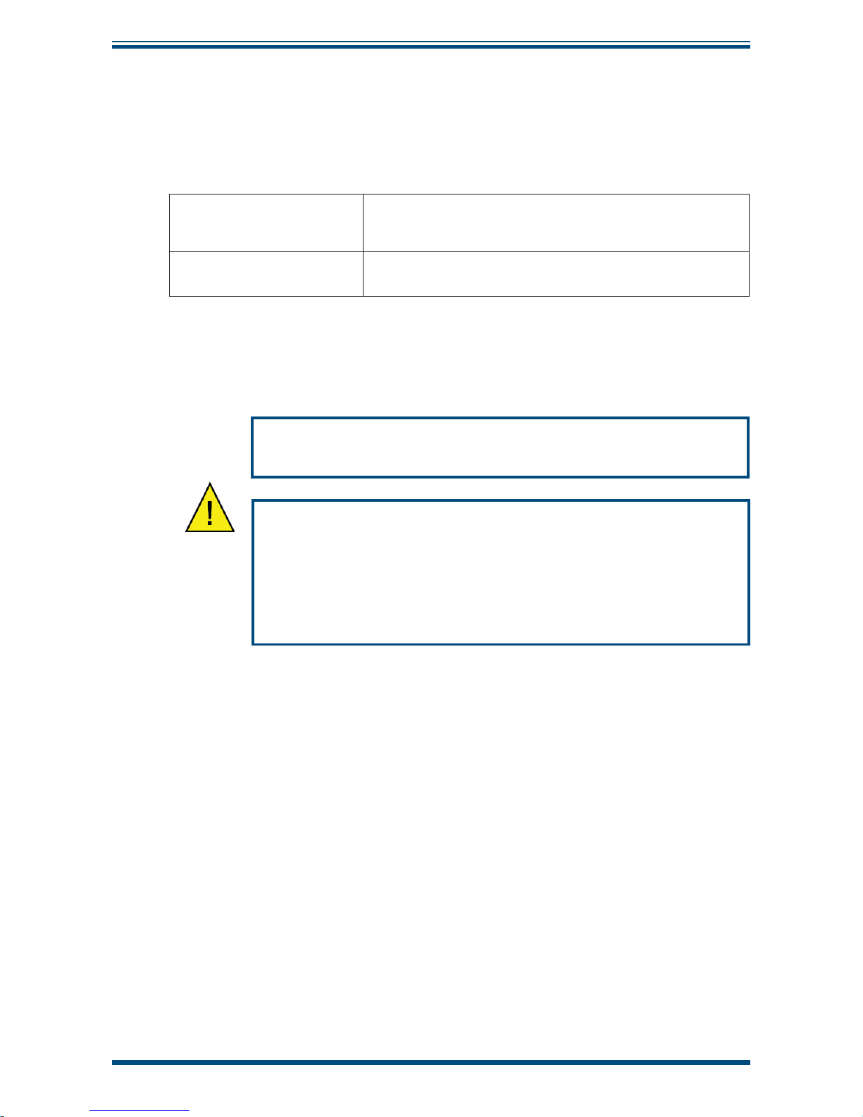
2.13 Gas Connection
To ensure that the sample gas is properly
conditioned a sampling system might be
required.
Contact Michell Instruments if you wish to order
a suitable sampling system.
Sample gas connections are made via the gas input and gas output ports located on
the back panel (XZR400A1), bottom panel (XZR400A2), side panel (XZR400A3) or front
panel (XZR400A4) of the analyzer.
Both the input and output gas connections are 1/8” stainless steel Swagelok® couplings.
NOTE: To facilitate ease of connection to the port, at least 75mm (3") of the
tubing coming out of the gas inlet port must be straight.
The method of connecting to the gas inlet and gas outlet ports is as follows:
1. Connect the gas source from the sample system to the Swagelok® fi tting
at the inlet port on the instrument using 1/8” stainless steel tubing.
Tighten the fi tting as much as possible by hand and tighten again with a
7/16” fl at wrench (approximately 1¼ turns).
2. Connect the gas outlet port in a similar manner to that described in
Step 1 using 1/8” stainless steel tubing.
If you undo the fi tting again and reconnect it, fi rst tighten up by
hand and then tighten using a 7/16” fl at wrench with no more
than a 1/8 turn.
DO NOT OVER-TIGHTEN.
NOTE: Maximum sample pressure is 2 barg (29 psig).
NOTE: Sample is vented to atmosphere. Depending on the location of the
analyzer it may require a vent line to a safe location that is freely ventilated.
Page 42

XZR400 Series User’s Manual
32 97472 Issue 3, August 2018
OPERATION
3 OPERATION
It is recommended that the user becomes familiar with Section 2 of this manual in which
all the equipment controls, indicators, the elements of the display and the overall menu
structure are described.
Prior to operation, the analyzer must have been connected to the correct electrical
power supply and the relevant analog and alarm outputs connected to external systems
as described in Section 2.
On delivery, the instrument will have been set-up with a standard set of default
parameters defi ning the operation of the analyzer. These parameters can be changed
as required by means of the
Main Menu.
3.1 General Operational Information
The input gas must be at a pressure of less than 2 barg (29 psig). A pressure regulator
is recommended when above 2 barg (29 psig) for better fl ow control. The outlet of the
system must be at atmospheric pressure.
NOTE: If the outlet is at higher pressure than atmospheric an optional process
pressure correction is necessary. Please consult Michell Instruments in this
case.
The instrument is designed to operate with a gas fl ow of 2 l/h ±1 l/h.
NOTE: For best results ensure that the sampling system is as close as possible
to the XZR400 Series Analyzer.
For all applications the sample gas is taken into the instrument via the gas inlet port
located on the bottom panel of the analyzer, from where it passes into an oven chamber.
The gas fl ow rate is then measured on the outlet side of the sample chamber, prior to
being exhausted from the instrument via the gas outlet port.
The fl ow, necessary for the sample gas circulation, is generated by the sensor oven
which utilizes the heat convection principle. The hot sample gas from the sensor oven is
pushed by the hot oven gases, which are still in the oven. On the way out of the oven
the sample gas cools, passing through the gas outlet port, and is carried away by the
main gas fl ow.
The XZR400 Series Analyzers are suitable for the measurement of oxygen in a wide
variety of clean and dry gases. It will not contaminate high purity gases and is safe for
use in critical semiconductor and fi bre optic manufacturing applications.
It is possible to continuously visualize the oxygen concentration in the range between
0.01 ppm and 25% oxygen. If required, the analyzer can display the MSRS voltage, the
oven temperature and the temperature of the cold junction in the thermocouple.
Page 43
XZR400 Series User’s Manual
Michell Instruments 33
OPERATION
3.2 Powering-up the System
Carefully check the electrical connection before applying the power.
Wall Mount Version
Switch the external disconnecting device supplying power
to the analyzer. This device does not have a built-in on/off
switch.
Portable and Rack
Versions
Switch the built-in on/off switch to the
ON position
Power-up the system. Observe all normal safety precautions during the powering-up
procedure.
Never allow sample gas to enter the analyzer when it is switched
off.
In the case of power breakdown for more than 1 hour it is
necessary to purge the analyzer with Nitrogen or instrument air
dew point < -40.
This will prevent any condensation due to the oven being off.
Maintain the fl ow rate at 2 l/h ±1 l/h.
Page 44

XZR400 Series User’s Manual
34 97472 Issue 3, August 2018
OPERATION
3.3 Warm-Up Period
Upon power up, the screen appears as shown below. The analyzer performs a series of
internal checks for about 5 seconds.
NOTE: Touch the French or English area to display the menu in the required
language.
French
1
Software version V0.1.7.ver
English
Figure 29
Start-up Screen
Wait about 15 minutes until the oven temperature reaches 634°C, indicated by the oven
temperature line.
The low temperature alarm is displayed digitally throughout the rise in oven temperature;
the general alarm contact is activated.
NOTE: A fl ow greater than 3.5 l/h prevents the correct rise in oven temperature.
Oven
Flow
Low temperature alarm
48.8ºC
7.5 l/h
Figure 30
Oven Temperature Screen
Page 45

XZR400 Series User’s Manual
Michell Instruments 35
OPERATION
If required, adjust the gas sample fl ow by operating the by-pass valve (B) and then the
end fl ow valve (A) to obtain a 2 ±1 l/h fl ow rate (C).
NOTE: For optional measurement do not fully close the by-pass valve.
AB
AB
Adjustment
View
Pump
NO
3
20:09:43
O
2
: 19.3 %
0,5....2....3,5
U
Flow l/h
C
Figure 31
Sample Flow Adjustment
Page 46

XZR400 Series User’s Manual
36 97472 Issue 3, August 2018
OPERATION
3.4 Main Screen
Once the temperature has been reached, the screen displays:
Adjustment
View
Pump
NO
3
20:09:43
O
2
: 19.3 %
0,5....2....3,5
U
Flow l/h
A
B
C
D
E
F
G
H
Figure 32
Main Screen
A
Measured oxygen concentration between 0.01 ppm and 25%. The maximum
measurement precision can only be obtained following an adjustment
performed after a minimum of 3 hours of operation. However, upon receipt
of the analyzer, this adjustment will have been performed in the factory as
shown in the manufacturing check and adjustment sheet.
B
Pump
ON/OFF button available on A1 or A4 models.
The
PUMP signal fl ashes when the pump is operating
C Screen number
D
Touch-sensitive
View area
E Message display area
F Sample gas fl ow between 0.5 and 3.5 l/h, shown by the cursor position
G
Touch sensitive
Adjustment area
Used to adjust the MSRS cell after changing the cell or the oven
H Current time
Page 47

XZR400 Series User’s Manual
Michell Instruments 37
OPERATION
3.5 Control Parameters Display
On the Measurement Display Screen (3) touch the VIEW area
The Control Parameters Screen (3.1) will appear.
Adjustment
CO
Adjustment
Maintenance
3.1
634.0ºC
30.7ºC
-122.76 mV
1036 mBar
2.5 L/h
0.00
Oven
Room temp
Sensor Voltage
Atm pressure
Flow
Control parameters
O2 27.35 ppm
Figure 33
Control Parameters Screen
This displays the following information about the analyzer.
Oven
Current temperature of the hot joint of the thermocouple
corresponding to oven temperature. This must be 634°C.
Temperatures 30°C below the reference and 50°C above the
reference trigger a general alarm.
Room Temperature
Measure taken on the motherboard. This measurement is only
used to compensate for the cold solder joint of the thermocouple.
Sensor Voltage
Measurement in mV of the voltage supplied by the measuring
cell, which must be between -300 and +250 mV. A value greater
than the upper limit generates a MSRS fault alarm.
Atm pressure
The pressure at the analyzer outlet must be near atmospheric
pressure (between 800 and 1750 mbar). A value above 1200
mbar and under 800 mbar generates an oxygen measurement
error. NOTE: If the pressure is greater than 1750 mbar,
the atmospheric pressure sensor can be damaged
irreversibly.
Flow
The sample's fl ow in l/hour must be 2 ±1 l/h. A fl ow value
below 0.5 or greater than 3.5 l/h generates a general fault alarm
displaying a Flow fault.
O2 Measured oxygen percentage
Return to Main Screen 3. The display returns to the Main Screen
automatically if the touch screen is not used for 2 minutes.
Adjust Displays the adjustment screen to calibrate the analyzer.
Maintenance
Displays the analyzer's parameter setting screen (access code,
outputs, alarm limits, time-stamp, RS485, fl ow corrections).
Page 48

XZR400 Series User’s Manual
38 97472 Issue 3, August 2018
OPERATION
3.5.1 Confi guration
To reach the Main Menu Screen enter the access code as follows.
• Touch the
VIEW area of Screen 3. The Control Parameters Screen is
displayed.
• Touch the
Maintenance area.
NOTE: To leave this screen touch
Cancel area.
• Touch the box labelled 0____
• Enter the access code on the keyboard. The default access code is 0.
• To correct an entry error press
• Touch the OK area.
Adjustment
CO
Adjustment
Maintenance
3.1
680.3C
30.7C
-122.76 mV
1036 mBar
2.5 L/h
0.00
Oven
Room temp
Sensor Voltage
Atm pressure
Flow
Control parameters
O2 27.35 ppm
Access code
Cancel
OK
789
456
1
0
23
0___
Min = 0
Max = 9999
Figure 34
Main Menu Access Screen
If the access code is incorrect the screen goes back to Screen 3.1.
If the access code is correct the Main Menu Screen is displayed (5).
Flow
Analog output Alarms
Auto adjustment System
Comm
Pressure
Main menu
5
Figure 35
Main Menu Screen
Page 49

XZR400 Series User’s Manual
Michell Instruments 39
OPERATION
3.5.2 Changing the Access Code
The default access code is 0000. To change this code proceed as follows:
NOTE: To leave a screen, touch
.
• Touch the
VIEW area of Screen 3. The Control Parameters Screen is
displayed.
Adjustment
CO
Adjustment
Maintenance
3.1
634.0ºC
30.7ºC
-122.76 mV
1036 mBar
2.5 L/h
0.00
Oven
Room temp
Sensor Voltage
Atm pressure
Flow
Control parameters
O2 27.35 ppm
• Touch the Maintenance area.
Flow
Analog output Alarms
Auto adjustment System
Comm
Pressure
Main menu
5
• Touch the System area.
Hour Misc.
System
Tue 18/02/2014 15:48:54
++ + ++
-- - --
5.5
• Touch the Misc tab
Page 50

XZR400 Series User’s Manual
40 97472 Issue 3, August 2018
OPERATION
Hour
System
5.5
634ºC
Setpoint
Language
New access code
English
****
Misc.
• Touch the New Access code area
Hour Misc.
System
5.5
634ºC
Setpoint
English
New access code
English
****
Access code
Cancel
OK
789
456
1
0
23
0___
Min = 0
Max = 9999
• Enter the new access code
• To correct an entry error, press the
area
• Press the
OK area
Page 51

XZR400 Series User’s Manual
Michell Instruments 41
OPERATION
3.6 The Main (Expert) Menu
This menu accesses all of the confi guration functions of the analyzer. Press the
corresponding area to display the required screen.
Flow
Analog output Alarms
Auto adjustment System
Comm
Pressure
Main menu
5
Figure 36
Main Menu Screen
Area Function Section
Analog output
Confi gures the 4-20 mA analog output 1 3.6.1
Alarms
Disables the 3 alarms (during adjustment and/or during
normal operation) and sets the threshold and the function
mode for alarm 1 and 2
3.6.2
Auto adjustment
Confi gures the automatic cyclical adjustment (adjust) of
the analyzer
Optional
3.6.3
System
Confi gures the analyzer timestamp function, oven
temperature, menu display language, Expert access
code and RS output confi guration (ModBus address with
RS485 or frame period with RS232).
3.6.4
Pressure
Confi gures the process pressure correction
Optional for all models
3.6.5
Returns to the Measurement Display Screen (3)
COM 232
Sets the frequency of the frame transmission
Optional
Cannot coexist with the RS485
3.6.6
COM 485
Sets the ModBus address of the analyzer and displays
the message frames received by the analyzer via the
RS485 interface
Cannot coexist with the RS232
3.6.6
Flow
Confi gures the gas sample fl ow correction based on its
density
3.6.7
Page 52

XZR400 Series User’s Manual
42 97472 Issue 3, August 2018
OPERATION
3.6.1 Analog 1
The Analog Output 1 screen (5.1) sets the parameters for the 0/4-20 mA output.
• Touch the area to select it and change it.
• Enter the new numeric value on the virtual keypad.
• Click
OK to confi rm or Cancel to discard the changes.
Analog 2
Analog output
5.1
4-20 mA
Start of scale
Unit
End of scale
Range
O2 Linear
0.10%
%
10.00%
0-20 mA
Analog 1
Figure 37
Analog Output Screen
Area Function
4-20 mA
Confi guration of the 0/4-20 mA analog output No 1.
LIN: the output voltage must be linearly proportional to the oxygen
measurement value.
LOG: the output voltage must be a logarithmic function with respect to
the oxygen measurement value. Use this option when the signal span is
greater than 3 decimal counts.
A current of 3.80 mA (4-20 mA output confi gured) or 21 mA is
automatically generated when there is a general fault if:
• oven temperature is lower than 30°C or higher than 50°C
from the setpoint
• thermocouple rupture
• fl ow less than 0.5 and greater than 3.5 l/h
• internal wiring fault
Start of scale
Confi guring the concentration for the low scale and the measurement
unit. Select a value and a unit corresponding to the concentration to be
measured.
Unit
Confi guration of the unit in which the value is expressed (% or ppm).
End of scale
Confi guring the high scale concentration and the measurement unit.
Select a value and a unit corresponding to the concentration to be
measured.
NOTE: the difference between the low scale and high scale value
is limited to three decimal places to ensure correct resolution.
This limitation only applies to a linear output type.
Range
Confi guration of the analog output (0-20 or 4-20 mA).
Returns to the Main Menu screen.
Analog 2
The information is similar to that of the Analog 1 menu and can be reached by touching
the Analog 2 area. When this option is not available, the display shows
Option not
available.
Page 53

XZR400 Series User’s Manual
Michell Instruments 43
OPERATION
3.6.2 Alarms
The Main Tab
The Alarms Screen sets the general behaviour for alarms 1 and 2.
• Touch the area to select it and change it.
• Click
OK to confi rm or Cancel to discard the changes.
Alarm 1
Alarms
5.3
No
Enable when adj
Disabled
No
Alarm 2Main
Figure 38
Alarm Screen (Main)
Area Function
Enable when adj
Sets the behaviour for alarms 1 and 2 exclusively during auto adjust
operations or manual.
•
No: exceeding the alarm threshold will not trigger the
relay for alarms 1 and 2 during adjustment operations, or
when alarm set off is confi gured by the user.
•
Ye s: exceeding the alarm threshold will trigger the relay
for alarms 1 and 2 during adjustment operations, or when
alarm set off is confi gured by the user.
Disabled
Sets the current behaviour for alarms 1 and 2 and that of the General
fault exclusively in normal mode of operation (excluding adjustment).
•
No: the alarms are operational; the corresponding alarm
will be activated when an alarm is triggered and/or a fault
occurs. This is the standard choice for the analyzer in
normal operation.
•
Ye s: no alarms will be activated regardless of the alarm and/
or fault present. Use this option during the commissioning
of the analyzer, especially before the wiring the alarms.
The blinking
Alarms Disabled message will be displayed
on the Measurement Display Screen (3).
NOTE: Operating with alarms disabled must only be done
temporarily, particularly during adjustments.
Alarm 1 tab
Touch the area to display the alarm 1 threshold change screen.
Alarm 2 tab
Touch the area to display the alarm 2 threshold change screen.
Returns to the Main Menu Screen.
Page 54

XZR400 Series User’s Manual
44 97472 Issue 3, August 2018
OPERATION
The Alarm 1 or Alarm 2 Tab
This screen is used to set the alarm function mode (high, low), the threshold and
hysteresis for the selected alarm 1 or 2.
It is used mainly to enable or disable the alarms during the adjustment phases and
during normal analyzer operation.
• Touch the area to select it and change it.
• Enter any new numeric value on the virtual keypad.
• Click
OK to confi rm or Cancel to discard the changes.
Main
Alarms
5.3
Low
Type
Threshold
Unit
Hysteresis
1.0%
%
0.1%
Alarm 2Alarm 1
Figure 39
Alarm Screen (Alarm 1)
Area Function
Type
Sets the behaviour for alarm (1 or 2 according to the highlighted tab).
•
Low: the alarm will be activated when the measurement value
is equal or below the threshold set for the Alarm threshold
line. The alarm must be disabled when the measurement
value is above the threshold set for the Alarm threshold line.
•
High: the alarm will be activated when the measurement value
is equal to or above the threshold set for the Alarm threshold
line. The alarm must be disabled when the measurement
value is below the threshold set for the Alarm threshold line.
Threshold
Confi gures the alarm threshold value. Select the value and unit in relation
to the future measurement.
Hysteresis
Sets the alarm 'delay' value to return to alarm-off condition. The greater
this value is, the more the return to alarm-off condition value must be
delayed. For example, with a hysteresis of 3ppm over a 15ppm alarm
value, the alarm is triggered at 15ppm, but returns to the alarm-off
position at a 12ppm value (15ppm - 3ppm).
Returns to the Main Menu Screen.
Page 55

XZR400 Series User’s Manual
Michell Instruments 45
OPERATION
3.6.3 Auto Adjustment (Optional)
Purpose
This function is used for the analyzer’s auto adjust at a set time and at regular intervals
set in hours or days. Solenoid valves connected to the D-Sub DA15 on the XZR400A2,
and 8 pin connector on the XZR400A1 control any adjustment gas and control gas
inputs. Additional contacts are used to launch the sequence.
Hardware confi guration
Peripheral equipment must be installed as indicated.
Parameter setting for auto adjust
The Auto Adjust Screen sets the array of parameters used for the analyzer's auto adjust.
• Touch the area to select it and change it.
• Enter the new numeric value on the virtual keypad.
• Click
OK to confi rm or Cancel to discard the changes.
Main Level
Auto adjustment
5.4.1
External trigger
T0 adj
Adjustment period
Unit
No
12:00
1 d
d
Process
Enable Start Process
Figure 40
Auto Adjustment Screen
The three tabs, Main, Level and Process are described next.
Page 56

XZR400 Series User’s Manual
46 97472 Issue 3, August 2018
OPERATION
Main Tab
Main Level
Auto adjustment
5.4.1
External trigger
T0 adj
Adjustment period
Unit
No
12:00
1 d
d
Process
Enable Start Process
Area Function
Enable/Disable Enables/disables the launch of the automatic adjustment.
Start
Management of the start of the auto-adjust procedure.
•
Start: the auto adjust sequence is launched immediately,
regardless of the other settings.
•
T0 start: the auto-adjust sequence is launched at the time
specifi ed by the area
T0 Adjust.
The interval is set by Adjustment period (see below).
External trigger
Management of an external launch control button (push-button or
dry contact from an external PLC) controlling the launch of the auto
adjust sequence (as opposed to the automatic launch of the Inter
Start and Inter Adjust commands).
•
No: pressing the external button connected to terminals
5-6 of the D-Sub DA15 connector or the 8 pluggable
pin connector will not allow the launch of the auto adjust
sequence.
•
Ye s : pressing the external button connected to terminals
5-6 of the D-Sub DA15 connector or the 8 pluggable pin
connector will allow the launch of the auto adjust sequence.
T0 adj Sets the start time of the next auto-adjust.
Adjustment
period
Adjustment interval
Sets the time interval in hours or days between two auto-adjust
sequences. See below.
Unit
d (day) or hr (hour)
Defi nes the time unit of the Adjustment interval.
Inter adjust:
Intervals in hours or days
between automatic
adjustments
Automatic
adjustment
sequence
Automatic
adjustment
sequence
To
next start
time
Page 57
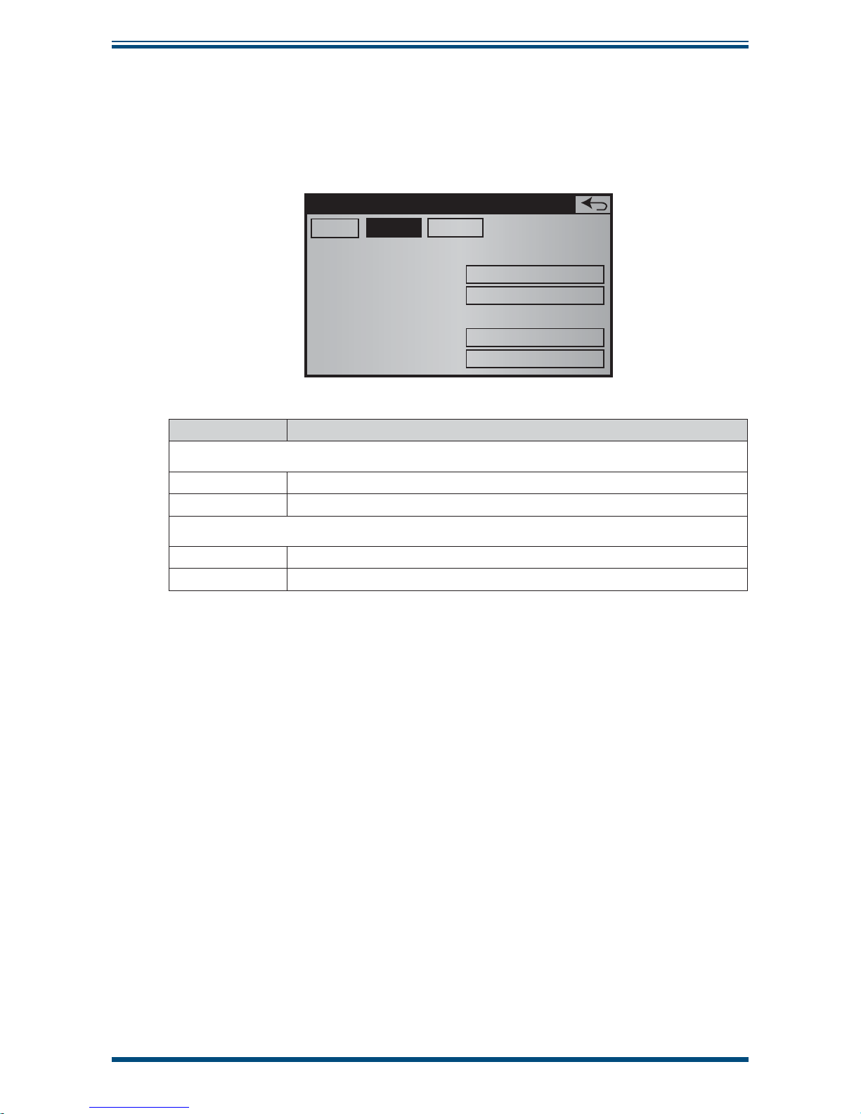
XZR400 Series User’s Manual
Michell Instruments 47
OPERATION
Level Tab
The Level tab of the Auto adjust screen defi nes the unit and the value of adjustment
and control gases.
Main
Auto adjustment
5.4.1
Standard gas:
Level
Unit
Control gas:
Level
Unit
5.00%
%
5.00%
%
ProcessLevel
Area Function
Standard gas
Level
Defi nes the value of adjustment gas
Unit
Defi nes the unit of adjustment gas
Control gas
Level
Defi nes the value of control gas
Unit
Defi nes the unit of control gas
Page 58

XZR400 Series User’s Manual
48 97472 Issue 3, August 2018
OPERATION
Process Tab
Main
Auto adjustment
5.4.1
Adjustment time
Control time
Purge time
Hold 4-20 mA
Alarms
Ctrl Adj Pressure
20 min
25 min
30 min
No
No
No
Level Process
Area Function
Adjustment
time
Duration in minutes of the adjustment sequence.
Control time Duration in minutes of the control sequence.
Purge time Duration in minutes of purging.
Hold 4-20 mA
Concerns the 4-20 mA analyzer outputs
•
No: 4-20 mA outputs will display the oxygen concentration
during the adjusting sequence start until the purge end.
•
Ye s: 4-20 mA outputs are locked to the value measured
before the adjustment sequence start until the end purge.
Alarms
Concerns the analyzer general fault alarm as well as Alarms 1 and 2
•
No: alarms will remain operational during the adjust
sequence start until the end of the purge.
•
Ye s: alarms will be disabled.
Ctrl Adj
Pressure
Gas adjustment and control gas bottle pressure checking
•
No: any pressure control on bottles of gas adjustment or
gas control will be carried out. In case of fault in at least one
of these bottles, the conformity of the adjustment or control
cannot be guaranteed.
•
Ye s: the adjustment sequence or control will stop if any
pressure fault is detected. The
No adjusting message
or
Control not possible will be displayed. The previous
adjustment will be retained.
Returns to the Main Menu Screen.
Page 59

XZR400 Series User’s Manual
Michell Instruments 49
OPERATION
Automatic Adjustment Usage
Launch Action
Manual
If external trigger has been selected, touch the dedicated push-button
(or launch via the contact controlled by the external PLC) to launch the
auto adjust sequence immediately.
Immediately
via the screen
Regardless of the confi guration for alternative launch modes, touch the
immediate start area to launch the auto adjust sequence immediately.
For defi ned
date and
interval
If adjustment period (time interval between adjustments) and T0
adj (start time for the next auto adjust) have been defi ned, the auto
adjust sequence is launched automatically at the scheduled time (T0
adj) and resumes cyclically after the adjustment period.
Example: interval adjustment 2h and T0 14h. If the operator pushes
the Start area T0 at 17:00, self adjustment will be disabled until the
next day to 14:00. It will then be started at 16:00, 18:00 and 20:00.
To stop the automatic sequence, touch the
Enable area.
3.6.4 System
This screen is used to update the analyzer's real-time time stamp clock, to set the oven's
temperature or the interval between two RS232 messages, as well as the factory reset.
• Touch the area to select it and change it.
• Enter the new numeric value on the virtual keypad.
• Click
OK to confi rm or Cancel to discard the changes.
Hour Tab
The Hour tab concerns the system timestamp.
• Touch the + and – area to set the current time and date.
NOTE: seconds will be resettled.
Hour Misc.
System
Tue 18/02/2014 15:48:54
++ + ++
-- - --
5.5
Page 60

XZR400 Series User’s Manual
50 97472 Issue 3, August 2018
OPERATION
Misc Tab
The Misc tab of the System screen concerns the oven temperature setpoint, the menu
display language and the access code modifi cation.
• Touch the + and – area to set
Hour
System
5.5
634ºC
Setpoint
Language
New access code
English
****
Misc.
Area Function
Setpoint
Enter the oven temperature value that the analyzer will use to operate.
The default value is 634°C. An unsuitable temperature setting reduces
the performance of the analyzer and can damage the MSRS oxygen
measuring cell.
Language
Touch the Language area. In the opened window, change the
displayed language. The new language will be applied at the next
start.
NOTE: the language selection is proposed if this choice was
not selected at the analyzer start.
New
access
code
Modifi es the expert level code. By default, the expert code is
0.
Warning: If the access code is forgotten the equipment will
need to be returned to the factory for Expert level code reset.
Factory
settings
The analyzer parameter values defaults are set at the factory, namely
• Oven temperature: 634°C
• Alarm No. 1 High mode, threshold: 3 ppm
• Alarm No. 2 High mode, threshold: 3.5 ppm
• Low scale and high scale, 4-20 mA output No. 1: 0.1 and
10 ppm
• Low scale and high scale, 4-20 mA output No. 2: 0.1 and
1000 ppm
Page 61

XZR400 Series User’s Manual
Michell Instruments 51
OPERATION
3.6.5 Total Pressure Correction (Optional)
This optional screen is used to adjust the low scale and the high scale of the external
pressure sensor, which is connected to D-Sub DA15 for all versions, except for the
XZR400A1 model, where the connection is carried out on the 8 pins connector. This
sensor compensates the total pressure in the MSRS cell.
When the gas pressure at the analyzer output is greater than the atmospheric pressure
sensor's upper limit (1,200 mbar), the total pressure adjustment is needed to guarantee
optimum operation of the analyzer.
The input signal from the external pressure sensor is a 4-20 mA analog signal representing
the output pressure of the analyzer. The signal enters the analyzer at terminals 11 and
12 of the D-Sub DA15 connector for all versions, except for the XZR400A1 model, where
the connection is carried out on pins 12 and 13 of the screw terminal.
Defective wiring/electrical supply of the total pressure sensor, or no connection of the
total pressure sensor’s 4-20 mA signal to the analyzer, generates a general fault alarm
and the display of a pressure fault message. This is not run if the sensor outputs a 0-5
V signal type.
In case of a pressure fault, the O
2
concentration will be displayed taking in account an
atmospheric pressure of 1000mbar. If the pressure of the measured gas is not within a
1000mbar ±20mbar bracket, the O2 concentration on the display will be off the relative
2% tolerance.
Pressure Correction Screen
• Touch the area to select it and change it.
• Enter any new numeric value on the virtual keypad.
• Click
OK to confi rm or Cancel to discard the changes.
Pressure correction
5.6
Start of scale
End of scale
0.0 bar abs
2.0 bar abs
Figure 41
Pressure Correction Screen
Area Function
Start of scale
Touch the area to enter the low scale pressure value of the external
sensor.
End of scale
Touch the area to enter the high scale pressure value of the external
sensor.
Returns to the Main Menu Screen.
Page 62

XZR400 Series User’s Manual
52 97472 Issue 3, August 2018
OPERATION
3.6.6 COMM
3.6.6.1 RS232
Area Function
Frame period
Sets the delay, in seconds, between two RS232 signal emissions, from
0 (no emission) to 999 seconds (one emission every about 16 minutes).
Returns to the Main Menu Screen.
3.6.6.2 RS485
Only available for analyzers equipped with this output.
Comm Screen
The COM RS485 screen sets the RS485 output parameters.
Comm
5.7
Speed
Data
Parity
Stop
Modbus address
1
9600 bps
8 bits
none
1
RS485
Figure 42
Comm Screen
Area Function
RS485
Indications of the RS485 interface connection parameters that cannot
be modifi ed.
• Speed: 9600 bauds
• Number of bits
• Parity: None
• Stop: 1
ModBus
address
The analyzer's ModBus slave address. Enter a value between 1 and 255,
including terminals.
Page 63

XZR400 Series User’s Manual
Michell Instruments 53
OPERATION
3.6.7 Flow
This screen is used to defi ne a fl ow correction factor depending on the density of the
gas being analyzed. Use this function to optimize the fl ow measurement depending on
the type of gas used.
Flow correction
1 : Air O2 N2 AR NO
5.8
2 : He
3 : CO2 NO2 N20
Figure 43
Flow Correction Screen
Area Function
Flow
correction
Selects the adjustment factor number (1, 2 or 3) depending on the gas
analyzed. For this choice, take the main gas into account.
Returns to the Main Menu Screen.
Page 64

XZR400 Series User’s Manual
54 97472 Issue 3, August 2018
CALIBRATION
4 CALIBRATION
The optimal measurement accuracy is reached when calibrating the analyzer after a
minimum of three hours of operation.
Calibration is done on a single point. The gas concentration adjustment should be
between 0.01 ppm and 25% oxygen.
Avoid calibration gas concentrations between 1,000 ppm
(0.1%) and 5,000 ppm (0.5%) as this is too close to the internal
reference.
It is possible to control the calibration effi ciency with a second gas, rated at a different
O2 value. A single cylinder with O2 at a known concentration is required for calibration. A
second cylinder with a different concentration can be used to verify calibration (Control
Gas).
BYPASS GAS OUTLET SENSOR GAS OUTLET
GAS INLET
ATTACH
HOSE TO
“GAS INLET”
PORT
CAL GAS
BOTTLE
REGULATOR
ATTACHED
XZR400 OXYGEN ANALYZER
USE STAINLESS STEEL TUBE
FOR TRACE OXYGEN
MEASUREMENTS
SET OUTPUT TO A
MAXIMUM OF 2 BARG
Figure 44
Calibration Procedure with XZR400A1
Page 65

XZR400 Series User’s Manual
Michell Instruments 55
CALIBRATION
4.1 Defi nitions
• Adjustment gas: an adjustment gas used in order for the analyzer to
correct a possible difference between the measured value and the actual
O2 content in the gas. The value which is written on the cylinder (or on
the relevant analysis certifi cate) must be entered in the fi eld
adjustment
gas section. The content can be in either % or ppm.
• Control gas: a gas with a different O
2
content than the adjustment gas.
It helps in verifying the calibration. The O2 content can be either in % or
ppm. This control is not compulsory.
• Process gas: the gas to be measured.
• Calibration duration: the period during which the adjustment gas
eliminates the process gas out of the internal sample path. The quality
of calibration will far be greater if the process gas is fully cleared away.
A longer period is necessary when the adjustment gas value is low and/
or when the difference between the process gas and the adjustment gas
is large. Calibration with % level oxygen gas requires approximately 5
minutes. Calibration with ppm level oxygen gas may require 30 minutes.
• Purging time: the period during which the process gas eliminates the
adjustment gas (or verifi cation gas) out of the internal sample path.
If a low O2 content (< 1000ppm) adjustment gas is used, a purge
time is necessary to allow the stabilization of the measurement
before starting the calibration sequence. This is even more
important if the process gas is going to be at a very different
concentration from that of the adjustment gas.
Page 66

XZR400 Series User’s Manual
56 97472 Issue 3, August 2018
CALIBRATION
4.1.1 ADJUSTMENT / Calibration Screen Pages 3.2, 3.2.1, 3.2.2 & 3.2.3
NOTE: Prior to commencement of the adjustment/calibration the alarms can
be disabled from screen page 5.3.
From the Main Screen press Adjustment to get to screen page 3.2.
Pressing the key from any of the Adjustment Screens will return to the previous
screen.
Adjustment Modif
3.2
12.4 %
8.02 %
2.00 %
Concentration :
Standard gas :
Control gas :
Adjustment
Figure 45
Screen Page 3.2
Ensure that the values on the Screen 3.2 are correct with respect to the calibration gas
cylinder or certifi cate. If they are correct press the
Adjustment button, this will take
you to Screen 3.2.2.
If the values do not match press the
Modify key, this will take you to Screen 3.2.1.
‘
MODIF’ . Incorrect Values
3.2.1
Standard gas :
Level
Unit
Control gas :
Level
Unit
Adjustment
Level Process
8.02 %
%
2.00 %
%
Figure 46
Screen Page 3.2.1
To change any of the values, press the relevant value key and use the numeric keypad
to modify the value.
To change the gas unit (% to ppm or ppm to %), press the unit key.
Press the
Process tab to check the Adjustment, Control and Purge times and correct
and modify if necessary.
Page 67

XZR400 Series User’s Manual
Michell Instruments 57
CALIBRATION
The length of time for each process should be long enough to ensure that the calibration
gas sample is stable during Adjustment and Control and that the calibration gas is
completely purged to a level close to normal operation (below any alarm threshold)
before switching back to measuring the process.
3.2.1
Adjustment time
Control time
Purge time
Adjustment
Level Process
5 min
5 min
5 min
Press the key to return to Screen 3.2 and press the Adjust key to start the
calibration procedure (Screen 3.2.2).
ADJUST . Correct Values
Cancel VALID
4-20mA
blocked
3.2.2
8.02 %
12.4 %
2.5 L/h
Standard gas :
Concentration O2
Flow
Adjustment
insert adjustment gas and VALID
Figure 47
Screen Page 3.2.2
Press the 4-20 mA key to select whether the output is frozen (blocked) or will follow the
gas concentration (active).
Open the gas cylinder to give a fl ow rate of 2 l/h ±1 l/h.
Wait for approximately 5 minutes for the concentration O2 value to be close to the
standard gas value and then press the
VALID key. This will bring up Screen 3.2.3.
An incorrect gas fl ow (0.5 < fl ow < 3.5 l/h) will prevent the
calibration sequence from starting.
An incorrect gas fl ow DURING the calibration will cancel the
sequence and screen page 3 will appear showing the message:
Impossible to calibrate: ow fault.
Page 68

XZR400 Series User’s Manual
58 97472 Issue 3, August 2018
CALIBRATION
Screen page 3.2.3 shows the O2 concentration in the adjustment gas and the time left
before the purge sequence.
Cancel
Op forced
after 1min
Adjustment progressing
3.2.3
8.02 %
19 min 58 s
12.4 %
2.5 L/h
Standard gas :
remaining time :
Concentration O2
Flow
Adjustment
Figure 48
Screen Page 3.2.3
During the calibration sequence it is possible to:
• Force calibration after 1 minute if the reading is stable. Press the Op
forced after 1min
key and screen page 3.2.4 will show (after 1 minute).
• Cancel calibration at any time. Press the
Cancel key and go to screen
page 3.2.8.
Cancel Calibration
Cancel
bleeding
Bleeding running
3.2.8
29 min 58 s
8.02 %
remaining time :
Concentration :
Adjustment
Figure 49
Screen Page 3.2.8
Pressing the Cancel bleeding key will return to the Main Screen.
Page 69

XZR400 Series User’s Manual
Michell Instruments 59
CALIBRATION
4.1.2 Diagnosis of the MSRS Sensor Status - Screen pages 3.2.4 to 3.2.7
While the control gas passes through the analyzer after a calibration sequence, the
MSRS sensor status is diagnosed to assess the working order of the analyzer.
The system compares the theoretical and measured concentration of the control gas.
To begin this diagnosis complete a calibration sequence (see Section 4.1.1). When the
calibration is over, screen page 3.2.4 will appear.
Alternatively if the reading was stable and the calibration was forced from screen page
3.2.3 by pressing the
VALID key, then screen page 3.2.4 will appear.
Measure VALID
Control
3.2.4
VALID
Measure
Passage of a control gas :
End of Adjustment :
Adjustment
Figure 50
Screen Page 3.2.4
Pressing the Measure key will show screen page 3.2.7. To return to the measurement,
close the adjustment gas cylinder. Pressing the VALID key will take you to screen page
3.2.8. A purge ends the calibration sequence.
Pressing the VALID key will start the Control gas process. The following screen page
3.2.5 will appear:
Cancel
VALID
Control
3.2.5
2.00 %
25 min 00 s
2.5 L/h
Control gas :
Control time
Flow
Adjustment
Figure 51
Screen Page 3.2.5
Pressing the Cancel key will take you to 3.2.8.
Page 70

XZR400 Series User’s Manual
60 97472 Issue 3, August 2018
CALIBRATION
Press the VALID key after opening the control gas cylinder to give a fl ow rate of 2 l/h
±1 l/h and waiting until the control gas has cleared the process gas away from the
internal sample path. Screen page 3.2.6 will appear:
Cancel
Op forced
after 1min
Control progressing
3.2.6
2.00 %
24 min 04 s
19.1 %
2.5 L/h
Standard gas :
remaining time :
Concentration O2
Flow
Adjustment
Figure 52
Screen Page 3-2-6
From this screen it is possible to:
• Force calibration after 1 minute if the reading is stable. Press the Op
forced after 1min
key and screen page 3.2.7 will show (after 1 minute).
• Cancel calibration at any time. Press the
Cancel key and go to screen
page 3.2.8.
At the end of the verifi cation period, the diagnosis will appear on screen page 3.2.7:
Cancel
VALID
Close ctrl gas bottle then VALID
=> Sensor OK
3.2.7
Adjustment
Figure 53
Screen Page 3-2-7
Three outcomes are possible and will be displayed as a message on the third row of
the screen:
• The analyzer is operative.
• The analyzer’s performance is not optimal. The MSRS sensor should be
replaced at some time in the near future.
• The analyzer’s performance is poor. Change the MSRS sensor immediately.
Pressing the
Cancel key will return to the Main Screen.
Closing the control gas cylinder and pressing the VALID key will take you to screen page
3-2-8.
Page 71

XZR400 Series User’s Manual
Michell Instruments 61
CALIBRATION
Managing The Alarms During The Calibration Sequence
The alarms can be active or inactive during the calibration sequence.
When
NO is on in the Active during ADJ section on screen page 5-3 the alarm contacts
are not active during the calibration sequence.
When
YES is on in the Active during ADJ section on screen page 5-3 the alarm contacts
will be activated during the calibration sequence and will respond according to the
confi guration set by the user.
De-Activation of Alarms
The alarms may be de-activated during installation and set-up. If the alarms are deactivated and the system detects a fault and/or an alarm threshold is passed, the alarm
relays are not activated. In this case a message describing the fault will appear at the
bottom of the default screen page 3.
When
NO is on in the Inhibit Alarms section the alarms are operative.
When
YES is on in the Inhibit Alarms section the alarms are de-activated.
Page 72

XZR400 Series User’s Manual
62 97472 Issue 3, August 2018
MAINTENANCE
5 MAINTENANCE
5.1 Troubleshooting Guide / Failure Analysis
Observation Cause Corrective Action
Mains power
plugged in and
switched on
but no display
present
Fuse blown • Replace mains fuse:
• Fuse Box: T2A/250V
• Mains socket: T6.3A/250
Analyzer not powered
BEWARE OF ELECTRIC SHOCK / BURN HAZARD
• Remove the analyzer cover
• Measure the main inlet voltage
• If the measured voltage is 90 to 264 V AC verify
the mains power to the analyzer
Display disconnected
BEWARE OF ELECTRIC SHOCK / BURN HAZARD
• Remove the analyzer cover
• Ensure the plugs of the 20-way ribbon cable are
connected to both the display PCB and the mother
board and that the wiring is intact
• Ensure the plugs of the 2-way cable are connected
to both the display PCB and the mother board and
that the wiring is intact
• Ensure the plugs of the 4-way cable are connected
to both the display PCB and the mother board and
that the wiring is intact
Faulty analyzer Return the analyzer to Michell Instruments for further
investigation
Page 73

XZR400 Series User’s Manual
Michell Instruments 63
MAINTENANCE
Observation Cause Corrective Action
Display
indicates
Low Temp
Analyzer initializing
Wait for up to 20 minutes to allow the analyzer's oven to
stabilize at the correct temperature
Power supply undervoltage
BEWARE OF ELECTRIC SHOCK / BURN HAZARD
• Remove the analyzer cover
• Measure the main inlet voltage
• If the measured voltage is 90 to 264 V AC verify the
mains power to the analyzer
Faulty heater
element
BEWARE OF ELECTRIC SHOCK / BURN HAZARD
• Remove the analyzer cover
• Measure the resistance of the heater across J11
pins 10-11
• If 8 < measured value < 11 replace the oven
15 V supply faulty
BEWARE OF ELECTRIC SHOCK / BURN HAZARD
• Remove the analyzer cover
• Measure voltage across J11 pin 11 to J12 pin 10
• If 13 V < measured value < 15 V return the analyzer
to Michell Instruments for further investigation
Thermocouple short
circuit
BEWARE OF ELECTRIC SHOCK / BURN HAZARD
• Remove the analyzer cover
• Replace the MSRS Sensor Assembly
• Recalibrate instrument
Gas fl ow exceeds
limit
Reduce the gas sample fl ow to 2 l/hr ±1 l/hr
Faulty analyzer
Return the analyzer to Michell Instruments for further
investigation
Page 74

XZR400 Series User’s Manual
64 97472 Issue 3, August 2018
MAINTENANCE
Observation Cause Corrective Action
Display
Indicates
T/C Fault
Open circuit
thermocouple
BEWARE OF ELECTRIC SHOCK / BURN HAZARD
• Remove the analyzer cover
• Check for faulty wiring of sensor - repair as
necessary
• Replace the MSRS / thermocouple sensor
assembly
• Recalibrate instrument
Broken thermocouple
BEWARE OF ELECTRIC SHOCK / BURN HAZARD
• Remove the analyzer cover
• Replace the MSRS / thermocouple sensor
assembly
• Recalibrate instrument
Faulty analyzer
Return the analyzer to Michell Instruments for further
investigation
Display
Indicates
Low Flow
Gas fl ow too low
BEWARE OF ELECTRIC SHOCK / BURN HAZARD
• Remove the analyzer cover
• Measure voltage across J11 pin 11 to J12 pin 10
• If 13 V < measured value < 15 V return the
analyzer to Michell Instruments for further
investigation
Leak in gas sample
path
BEWARE OF ELECTRIC SHOCK / BURN HAZARD
• Remove the analyzer cover
• Ensure all gas fi ttings are tight
• If the problem persists return the analyzer to
Michell Instruments for further investigation
Faulty electronic fl ow
meter
Return the analyzer to Michell Instruments for further
investigation
Faulty analyzer
Return the analyzer to Michell Instruments for further
investigation
Display
Indicates
High Flow
Gas fl ow too high
• Open the fl ow adjustment valve
• Close the bypass valve
• Adjust both valves to achieve a gas sample fl ow
to 2 l/hr ± 1 l/hr
Faulty electronic fl ow
meter
Return the analyzer to Michell Instruments for sensor
replacement
Faulty analyzer
Return the analyzer to Michell Instruments for further
investigation
Page 75

XZR400 Series User’s Manual
Michell Instruments 65
MAINTENANCE
Observation Cause Corrective Action
Display
indicates
Sensor Fault
Faulty wiring to sensor
BEWARE OF ELECTRIC SHOCK / BURN HAZARD
• Remove the analyzer cover
• Check wiring from MSRS sensor assembly to J12
pin 1-3
• Replace the MSRS / thermocouple sensor
assembly
Faulty sensor
BEWARE OF ELECTRIC SHOCK / BURN HAZARD
• Remove the analyzer cover
• Replace the MSRS / thermocouple sensor
assembly
Faulty analyzer
Return the analyzer to Michell Instruments for further
investigation
Display
indicates
Pressure Fault
Internal pressure
sensor fault
Return the analyzer to Michell Instruments for further
investigation
No signal from
external pressure
sensor
BEWARE OF ELECTRIC SHOCK / BURN HAZARD
• Remove the analyzer cover
• Check wiring to ensure 4-20 mA input signal is
present J12 pin 9-10
• Replace external sensor if problem persists
No power to external
pressure sensor
Check the power supply to external sensor
Faulty analyzer
Return the analyzer to Michell Instruments for further
investigation
Calibration gas
measurement
fault
Gas measures out of
specifi cation
Calibrate analyzer
Calibration gas empty Check calibration gas cylinder - replace if empty
Faulty analyzer Return the analyzer to Michell Instruments for further
investigation
After calibration
and during
calibration gas
verifi cation
O
2
outside
tolerance
Unstable measurement Wait for measurement to stabilize
Sensor gas path leak
BEWARE OF ELECTRIC SHOCK / BURN HAZARD
• Remove the analyzer cover
• Ensure all gas fi ttings are tight
• If the problem persists return the analyzer to
Michell Instruments for further investigation
Faulty MSRS Sensor
BEWARE OF ELECTRIC SHOCK / BURN HAZARD
• Remove the analyzer cover
• Replace the MSRS / thermocouple sensor
assembly
Faulty analyzer Return the analyzer to Michell Instruments for further
investigation
Page 76

XZR400 Series User’s Manual
66 97472 Issue 3, August 2018
APPENDIX A
Appendix A
Technical Specifi cations
Page 77
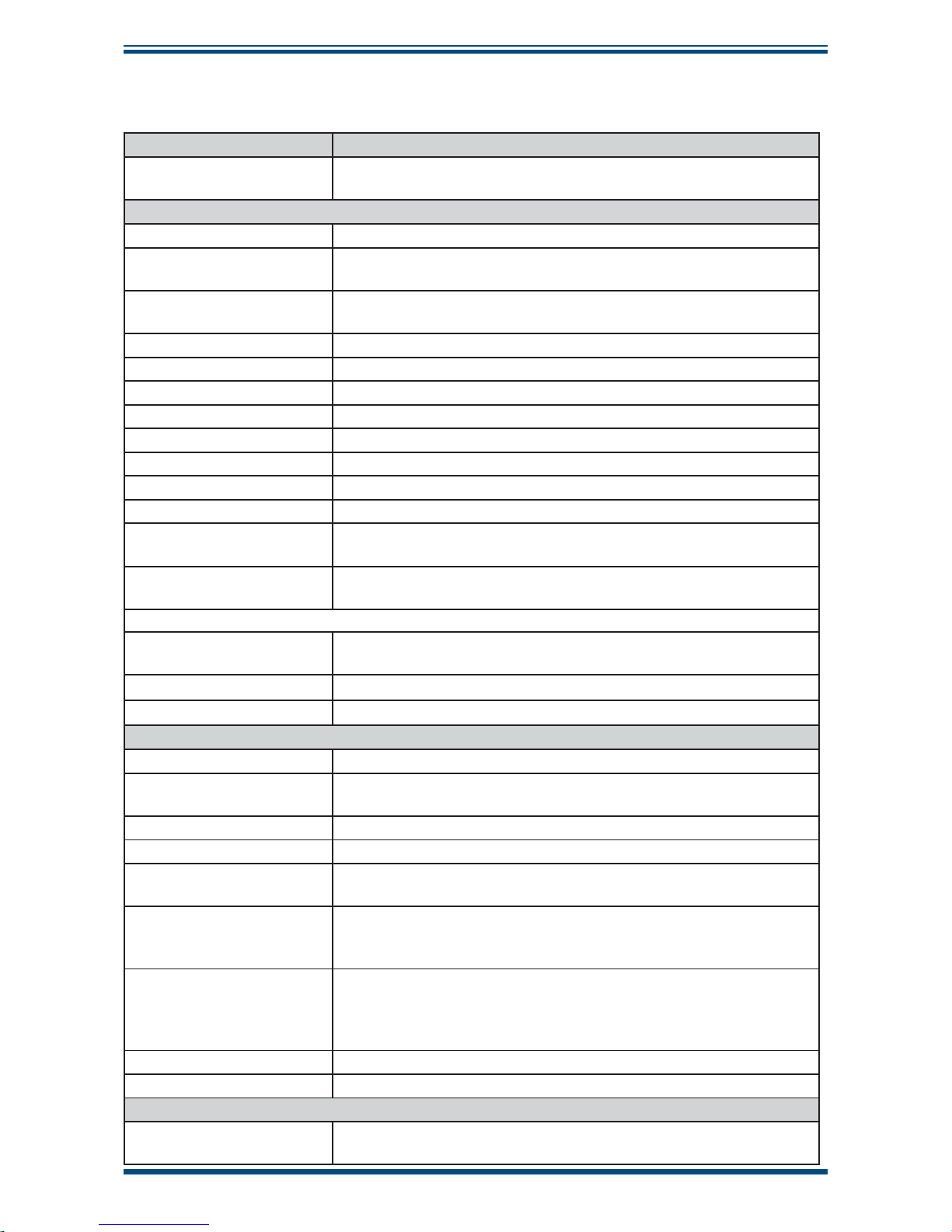
XZR400 Series User’s Manual
Michell Instruments 67
APPENDIX A
Appendix A Technical Specifi cations
Sensor Type
Measurement Principle
Zirconium Oxide Sensor with Metallic Sealed Reference
and S Type thermocoupe
Performance
Gas Clean, dry, oil free with particles less than 3 m
Measurement Range
0.1 ppm up to 25% O
2
Extended ranges available up to 0 to 100% O
2
Lowest detectable limit
(LDL)
0.1ppm(v) O
2
Accuracy (Intrinsic Error) Less than 2% of reading
Response Time < 11 seconds
Repeatability ±0.1% of reading
Stability 1% per month
Linearity Better than ±1%
Drift <1% of reading per week
Sample Flow Rate 1 to 3 Nl/h with built-in fast loop
Maximum Sample Pressure 2 barg (29 psig)
Maximum Sample
Temperature
+100°C (+212
°F)
Atmospheric Pressure
Compensation
Built-in as standard
Optional sensor
Moisture sensor
Easidew sensor can be fi tted as an option. Please, see a separate
datasheet for full specifi cations.
Measurement range -100 °C to + 20 °C
Sample Flow rate 60 to 300 Nl/hour
Outputs
Analog Output 0, 1 or 2 off 0/4-20 mA Linear with Galvanic Isolation output
Digital Communications
Output
Modbus RTU over RS485 protocol (Standard on XZR400A1)
RS232 output (optional)
Output Load Over 1,000
Self-Diagnostics Via HMI
Output Ranges
0.0 ppm to 1ppm up to 0 to 25% O
2
Extended ranges available up to 0 to 100% O2
Alarms
2 threshold alarms, freely confi gurable
1 general fault alarm including fl ow alarm
1 fl ow alarm (optional)
Display Resolution
0.01 ppm between 0.1 ppm and 10 ppm
0.1 ppm between 10 ppm and 10,000 ppm
0.01% between 1 to 10%
0.1% between 10 to 25%
Power Supply 90 to 264 V AC, 47/63 Hz
Power Consumption 50 VA
Operating Conditions
Ambient Temperature
Range
0 to +55°C (+32 to +131°F)
Page 78

XZR400 Series User’s Manual
68 97472 Issue 3, August 2018
APPENDIX A
Sensor Temperature Optimized at 634°C
Operating Humidity 5 to 90% RH without condensation
Mechanical Specifi cation
Model Dimensions Weight Gas Connectors
Ingress
Protection
Rack mount: 19’’, 3U, 482.5 x 133 x 371.5mm 10kg 1/8" IP20
Wall mount: 200 x 220 x 290mm 5kg 6 mm IP40
Bench mount: 290 x 260 x 236mm 5.2kg 6 mm IP20
Transportable: 450 x 300 x 330mm 13.5kg 6 mm IP40
Sample Gas Connections All gas connections are Swagelok (MALE) Fittings (316 SS)
Page 79

XZR400 Series User’s Manual
Michell Instruments 69
APPENDIX B
Appendix B
Modbus (RTU)
over RS485
Page 80

XZR400 Series User’s Manual
70 97472 Issue 3, August 2018
APPENDIX B
Appendix B Modbus (RTU) over RS485
B.1 Port Confi guration
• Speed: 9600 bauds
• No parity
• 8 bits
• 1 stop
• No handshaking
B.2 Hardware Confi guration
16 way terminal block connections
1 2 3 4 5 6 7 8 9 10111213141516
• pin 14 RS485 B - Data (-)
• pin 15 RS485 A - Data (+)
• pin 16 RS485 0V
Page 81

XZR400 Series User’s Manual
Michell Instruments 71
APPENDIX B
B.3 RS485 Register Map
Name
Address
[Hex]
Address
[Dec]
Modbus
Command
Type
[R/W]
Data Type Notes
Standard
Access
Expert
Access
DISPLAY PARAMETERS
O2 Measurement 0x100 256 3 R 32 Bit Real
0-250 000ppm
(IEEE-754)
Yes Yes
Oven Temperature 0x104 260 3 R 32 Bit Real (IEEE-754) Yes Yes
Ambient
Temperature
0x108 264 3 R 32 Bit Real (IEEE-754) Yes Yes
MSRS Sensor
Voltage
0x10C 268 3 R 32 Bit Real (IEEE-754) Yes Yes
Atmospheric
Pressure
0x110 272 3 R 32 Bit Real (IEEE-754) Yes Yes
Flow 0x114 276 3 R 32 Bit Real (IEEE-754) Yes Yes
ADJUSTMENT PARAMETERS
Adjustment Gas 0x120 288 3/16 R/W 32 Bit Real (IEEE-754) Yes Yes
Control Gas 0x124 292 3/16 R/W 32 Bit Real (IEEE-754) Yes Yes
Adjustment
Duration
0x128 296 3/6 R/W 16 Bit
ADJ.Gas Time
[Mins]
Yes Yes
Control Duration 0x12A 298 3/6 R/W 16 Bit
Control Gas Time
[Mins]
Yes Yes
Purge Duration 0x12C 300 3/6 R/W 16 Bit
Duration of
Purge
[Mins]
Yes Yes
Start Adjustment
TBA TBA 3 R 16 Bit Yes Yes
CONFIGURATION
Oven Set
Temperature
0x160 352 3/16 R/W 32 Bit Real
634 Nom (IEEE-
754)
No Yes
ANALOG OUTPUT 1
Type: Lin / Log 0x150 336 2/5 R/W Bit
Bit X 0=Lin
1=Log
No Yes
Low Limit 0x130 304 3/16 R/W 32 Bit Real (IEEE-754) No Yes
High Limit 0x134 308 3/16 R/W 32 Bit Real (IEEE-754) No Yes
ANALOG OUTPUT 2
Type: Lin / Log 0x150 336 2/5 R/W Bit
Bit X 0=Lin
1=Log
No Yes
Low Limit 0x138 312 3/16 R/W 32 Bit Real (IEEE-754) No Yes
High Limit 0x13C 316 3/16 R/W 32 Bit Real (IEEE-754) No Yes
ALARM OUTPUT 1
Type 0x150 336 2/5 R/W Bit
Bit X 0=Lin
1=Log
No Yes
Threshold 0x140 320 3/16 R/W 32 Bit Real (IEEE-754) No Yes
ALARM OUTPUT 2
Type 0x150 336 2/5 R/W Bit
Bit X 0=Low
1=High
No Yes
Threshold 0x144 324 3/16 R/W 32 Bit Real (IEEE-754) No Yes
STATUS Byte 0x154 340 3 R Bit See table below No Yes
Firmware Revision 0x158 344 3 R Bit
207=FW Rev
2.07
Yes Yes
Page 82

XZR400 Series User’s Manual
72 97472 Issue 3, August 2018
APPENDIX B
STATUS BYTE
Bit Description (Confi guration) Bit Description (Options)
0 Calibration Error 16 2nd 4-20 mA
1 0=FR (French) 1=GB (English) 17 Automatic calibration
2 1=DE (German) 0=French/English 18 Unused Bit
3 Unused Bit 19 Unused Bit
4 1=Alarms active during manual calibration 20 External pressure measurement
5 1=Disable analog outputs during manual calibration 21 Flow alarm (Alarm 4)
6 1=Alarms active during automatic calibration 22 Pump state
7 1=Disable analog outputs during automatic calibration 23 RS232
8 1=Automatic calibration active 24 RS485
9 External pressure control 25 Cleaning
10 External calibration password 26 Pressure sensor
11 Unused Bit 27 Unused Bit
12 Pump state 28 Unused Bit
13 Unused Bit 29 Unused Bit
14 Unused Bit 30 Unused Bit
15 Unused Bit 31 Unused Bit
Page 83

XZR400 Series User’s Manual
Michell Instruments 73
APPENDIX C
Appendix C
RS232 Serial Output
Page 84

XZR400 Series User’s Manual
74 97472 Issue 3, August 2018
APPENDIX C
Appendix C RS232 Serial Output
C.1 Port Confi guration
•
• Speed: 9600 bauds
• No parity
• 8 bits
• 1 stop
• No handshaking
C.2 Hardware Confi guration
The wiring cable should be equipped with 1 DB9 female plug and bare wire connectors
and connected as follows:
9
8
7
6
5
4
3
2
1
8
9
10
11
12
13
14
15
16
1
2
3
4
5
6
7
DB9
16 way
terminal block
DB9
16 way
terminal block
pin 2 pin 15 Tx
pin 3 pin 14 Rx
pin 5 pin 16 Ground
strap 7-8
(on same connector)
Page 85

XZR400 Series User’s Manual
Michell Instruments 75
APPENDIX C
C.3 RS232 Command List
Mnemonic ASCII Value
_OXY
O
2
concentration
XX.XX
or X.XXE±XX
_TEM
Oven temperature XXX.XX
_UMV
MSRS voltage XXX.XX
_AMB
Ambient temperature XX.XX
_ALR
K1, K2, K3 Relay status
K1 +K2 +K3 = from 0 to 7
(1) (2) (4)
X
_CAL
Sets self calibration after 10 minutes bleed
RECEIPT
PURGE?
_FIN
Sets a 5 minute bleed in case of failure in calibration
RECEIPT
DEFAULT
_ACQ
Acknowledges the alarms RECEIPT
_ETA
Display of calibration gas value XX.XX
E_ETA_X.XX
Set of calibration gas value X.XX
_STP
Display of oven temperature set point XXX.XX
E_STP_XXX.XX
Set of oven temperature XXX.XX
_AL1
Display of fi rst alarm level XXX.XX
E_AL1
Set of fi rst alarm level XX.XX
_AL2
Display of second alarm level XXX.XX
E_AL2
Set of second alarm level XX.XX
_NET
Starts self cleaning RECEIPT
_YYY
Unknown entry ERROR
_TCA
Measured oven temperature + coef. due to
adjustment
XX.XX
_BRK
Allows for: Ending the bleed during calibration
Ending self cleaning and start cooling down
XX.XX
_PAB
Value of atmospheric pressure XXXX.XX
_ indication corresponds to the space bar
indication corresponds to the return key
Table 2 RS232 Commands
Page 86

XZR400 Series User’s Manual
76 97472 Issue 3, August 2018
APPENDIX D
Appendix D
Extended Operating Range
(Optional)
Page 87

XZR400 Series User’s Manual
Michell Instruments 77
APPENDIX D
Appendix D Extended Operating Range - (Optional)
This option should be requested at the time of order stating the maximum oxygen
percentage required - 0 to 30% or 0 to 50%.
The default range is 0 to 25%.
NOTE: If an extended range is supplied then this will result in a reduction in
resolution and accuracy below 1% O2.
WARNING: If an extended range is purchased ensure that the
analyzer has been cleaned for oxygen service before use.
Page 88

XZR400 Series User’s Manual
78 97472 Issue 3, August 2018
APPENDIX E
Appendix E
Process Pressure Correction
(Optional)
Page 89
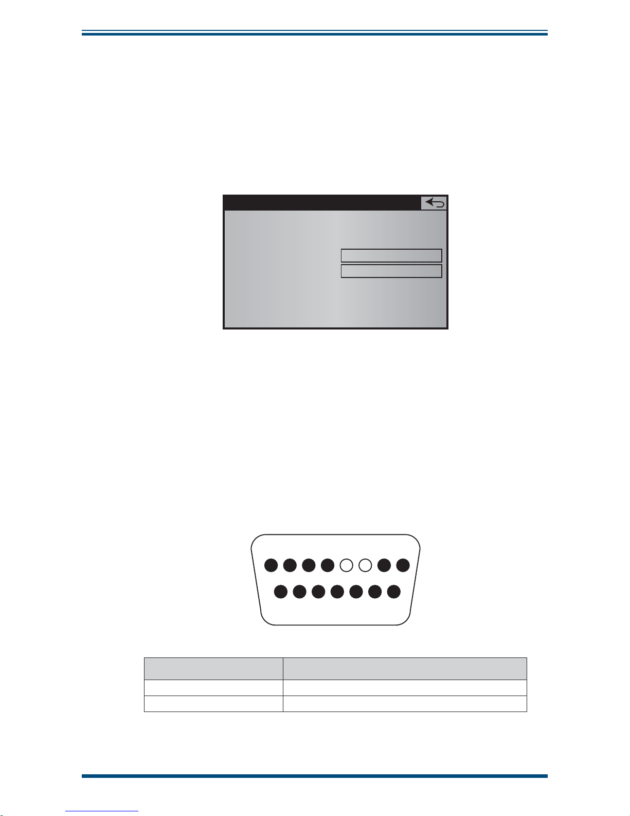
XZR400 Series User’s Manual
Michell Instruments 79
APPENDIX E
Appendix E Process Pressure Correction - (Optional)
When the process gas pressure is out of the atmospheric pressure range, the process
pressure correction is required to guarantee the optimal effi ciency of the analyzer.
The input signal is a 4-20 mA analog signal from an external pressure transmitter
installed by the user at the outlet side of the process.
The following screen is used to confi gure the scale range:
Pressure correction
5.6
Start of scale
End of scale
0.0 bar abs
2.0 bar abs
Figure 54
Pressure Correction Screen
An input signal of 4 mA corresponds to the low scale set value.
A input signal of 20 mA corresponds to the high scale set value.
E.1 Process Pressure Correction Input Connections
The 4-20 mA pressure transmitter signals should be connected to the DB15 socket on
the rear panel of the analyzer.
12
910111213 14 15
345678
Contact No Function
5 (+) 4-20 mA / analog input of process pressure
6 (+) 4-20 mA / analog input of process pressure
Page 90

XZR400 Series User’s Manual
80 97472 Issue 3, August 2018
APPENDIX F
Appendix F
Flow Fault Contact
(Optional)
Page 91

XZR400 Series User’s Manual
Michell Instruments 81
APPENDIX F
Appendix F Flow Fault Contact - (Optional)
In normal conditions, the fl ow is between 0.5 l/h and 3.5 l/h, the contact is closed and
potential free.
The relay switching capability is 150 W max (up to 5 A at 250 V AC or 5 A at 30 V DC).
F.1 Flow Fault Output Connections
Access to the fl ow fault contact is via the DB15 socket on the rear panel of the analyzer.
12
910111213 14 15
345678
Contact No Function
1 Flow fault contact
2 Flow fault contact
Page 92

XZR400 Series User’s Manual
82 97472 Issue 3, August 2018
APPENDIX G
Appendix G
Commutable Scale
(Auto-Ranging)
Page 93

XZR400 Series User’s Manual
Michell Instruments 83
APPENDIX G
Appendix G Commutable Scale (Auto-Ranging)
This option allows following the O2 concentration:
• Between 0 and 10 ppm on the fi rst 4-20 mA output
• Between 0 and 100ppm, 0 and 1000ppm, 10 and 10000ppm, or
1 and 25% on the second 4-20 mA output
The alarm contacts 1 and 2 indicate the beginning and the end of the scale used on the
second 4-20 mA output.
Settings are indicated below:
4-20 mA
output
Low Scale Up Scale
Alarm 1
Contact
Position
Alarm 2
Contact
Position
No 1 0 10ppm
No 2 0 100ppm Open Open
0 1000ppm Closed Open
10ppm 10000ppm Open Closed
1% 25% Closed Closed
Page 94

XZR400 Series User’s Manual
84 97472 Issue 3, August 2018
APPENDIX H
Appendix H
Optional moisture sensor
Page 95

XZR400 Series User’s Manual
Michell Instruments 85
APPENDIX H
Appendix H Optional moisture sensor
The XZR400 rack mount can be supplied with an Easidew moisture sensor fi tted in the
bypass leg to measure the moisture (dew point) of the sample. The sensor is capable of
measuring dew point from -100°C to +20°C dew point. If supplied with a moisture sensor,
dew point will be displayed underneath the oxygen concentration as shown below.
In the control parameters page, the dew point is displayed to the right of the O2 concentration
as shown in fi gure 56.
In the main menu page, press the button labelled 'DP Sensor' to access the 4 to 20mA
confi guration.
Figure 55
Main Page
Figure 56
Control Parameters Page
Figure 57
Main Menu
Page 96

XZR400 Series User’s Manual
86 97472 Issue 3, August 2018
APPENDIX H
Even though the dew-point sensor located inside the analyzer, it is considered an external device by
the fi rmware. In the DP Sensor page, you can confi gure the intput range from the dew-point sensor
by pressing the Start and/or End of scale buttons and adjusting in the normal way. Only adjust these
settings if you have already altered the range of the Easidew transmitter.
NOTE: The analyzer will require a total fl ow of 60 to 300 Nl/hour (1 to 5 Nl/min) to ensure optimum
response from the Easidew sensor.
Figure 58
DP Sensor Page
Page 97

XZR400 Series User’s Manual
Michell Instruments 87
APPENDIX I
Appendix I
Quality, Recycling
& Warranty
Information
Page 98

XZR400 Series User’s Manual
88 97472 Issue 3, August 2018
APPENDIX I
Appendix I Quality, Recycling & Warranty Information
Michell Instruments is dedicated to complying to all relevant legislation and directives.
Full information can be found on our website at:
www.michell.com/compliance
This page contains information on the following directives:
• ATEX Directive
• Calibration Facilities
• Confl ict Minerals
• FCC Statement
• Manufacturing Quality
• Modern Slavery Statement
• Pressure Equipment Directive
• REACH
• RoHS2
• WEEE2
• Recycling Policy
• Warranty and Returns
This information is also available in PDF format.
Page 99

XZR400 Series User’s Manual
Michell Instruments 89
APPENDIX J
Appendix J
Analyzer Return Document
&
Decontamination Declaration
Page 100

XZR400 Series User’s Manual
90 97472 Issue 3, August 2018
APPENDIX J
Appendix J Analyzer Return Document & Decontamination Declaration
F0121, Issue 2, December 2011
'HFRQWDPLQDWLRQ&HUWL¿FDWH
IMPORTANT NOTE: Please complete this form prior to this instrument, or any components, leaving your
site and being returned to us, or, where applicable, prior to any work being carried out by a Michell
engineer at your site.
Instrument Serial Number
Warranty Repair? YES NO Original PO #
Company Name Contact Name
Address
Telephone # E-mail address
Reason for Return /Description of Fault:
Has this equipment been exposed (internally or externally) to any of the following?
Please circle (YES/NO) as applicable and provide details below
Biohazards YES NO
Biological agents YES NO
Hazardous chemicals YES NO
Radioactive substances YES NO
Other hazards YES NO
Please provide details of any hazardous materials used with this equipment as indicated above (use continuation sheet
if necessary)
Your method of cleaning/decontamination
Has the equipment been cleaned and decontaminated? YES NOT NECESSARY
Michell Instruments will not accept instruments that have been exposed to toxins, radio-activity or bio-hazardous
PDWHULDOV)RUPRVWDSSOLFDWLRQV LQYROYLQJVROYHQWVDFLGLFEDVLFÀDPPDEOHRUWR[LFJDVHVDVLPSOHSXUJHZLWKGU\
JDVGHZSRLQW&RYHUKRXUVVKRXOGEHVXI¿FLHQWWRGHFRQWDPLQDWHWKHXQLWSULRUWRUHWXUQ
Work will not be carried out on any unit that does not have a completed decontamination declaration.
Decontamination Declaration
I declare that the information above is true and complete to the best of my knowledge, and it is safe for Michell
personnel to service or repair the returned instrument.
Name (Print) Position
Signature Date
 Loading...