

Page 1
XTC601
Thermal Conductivity Analyzer
User’s Manual
97400 Issue 2
July 2015
Page 2

Please ll out the form(s) below for each instrument that has been purchased.
Use this information when contacting Michell Instruments for service purposes.
Analyzer
Code
Serial Number
Invoice Date
Location of Instrument
Tag No
Analyzer
Code
Serial Number
Invoice Date
Location of Instrument
Tag No
Analyzer
Code
Serial Number
Invoice Date
Location of Instrument
Tag No
Page 3
XTC601
For Michell Instruments' contact information please go to
www.michell.com
© 2015 Michell Instruments
This document is the property of Michell Instruments Ltd. and may not be copied or
otherwise reproduced, communicated in any way to third parties, nor stored in any Data
Processing System without the express written authorization of Michell Instruments Ltd.
Page 4

XTC601 User’s Manual
Contents
Safety ...............................................................................................................................vii
Electrical Safety ..........................................................................................................vii
Hazardous Area Safety .................................................................................................ix
Pressure Safety ............................................................................................................ x
Temperature Safety ...................................................................................................... x
Toxic Materials ............................................................................................................. x
Repair and Maintenance ............................................................................................... x
Calibration ................................................................................................................... x
Safety Conformity ........................................................................................................ x
Abbreviations ......................................................................................................................xi
1 INTRODUCTION ................................................................................................1
1.1 Features ............................................................................................................ 2
1.2 Applications ....................................................................................................... 3
1.3 O-Ring Selection ................................................................................................. 3
2 OPERATION ......................................................................................................4
2.1 Preparation ........................................................................................................ 4
2.2 Powering up the Analyzer .................................................................................... 5
2.3 User Interface .................................................................................................... 6
2.3.1 Interface Controls ......................................................................................... 6
2.3.2 ‘ESC’ Button .................................................................................................. 7
2.3.3 ‘Up/Down Arrow’ Buttons ............................................................................... 7
2.3.4 ‘ENTER’ Button ............................................................................................. 7
2.4 Menu Structure .................................................................................................. 8
2.4.1 Menu Map .................................................................................................... 9
2.5 Front Pages (No Passcode Required) .................................................................... 9
2.5.1 Main Page .................................................................................................. 10
2.5.2 Chart Page ................................................................................................ 11
2.5.3 Secondary Parameters Page ......................................................................... 12
2.5.4 Target Gas Min/Max Page ........................................................................... 12
2.5.5 Alarms Log Pages ....................................................................................... 13
2.6 Info Page ........................................................................................................ 13
2.7 User Set-Up Variables (Passcode Required) ........................................................ 14
2.7.1 Settings Page .............................................................................................. 15
2.7.2 Human Machine Interface (HMI) Page .......................................................... 16
2.7.3 Reset Page ................................................................................................. 16
2.7.4 Outputs Page .............................................................................................. 17
2.7.5 External Compensation Page ........................................................................ 18
2.7.6 External Sensor Page .................................................................................. 19
2.7.7 Clock Page .................................................................................................. 20
2.7.8 Field Cal Page ............................................................................................. 20
2.7.9 Status LED or Light Guide ............................................................................ 21
3 CALIBRATION ..................................................................................................22
3.1 1 Point Calibration ............................................................................................ 23
3.2 2 Point Calibration ........................................................................................... 24
3.3 Field Calibration Reset ...................................................................................... 25
4 INSTALLATION ................................................................................................26
4.1 Unpacking ........................................................................................................ 27
4.2 System Components ......................................................................................... 27
4.2.1 Casing ........................................................................................................ 28
4.3 Set-Up ............................................................................................................. 28
iv 97400 Issue 2, July 2015
Page 5

XTC601 User’s Manual
4.4 Mechanical Installation ...................................................................................... 29
4.4.1 Gas Connection Tape ................................................................................... 30
4.4.2 Sample Gas Requirements ........................................................................... 30
4.4.3 Calibration Gases ........................................................................................ 30
4.5 Electrical Installation ......................................................................................... 31
4.5.1 Power Supply and Input/Output Signal ......................................................... 31
4.5.2 Power Supply (PL9 - Green) ........................................................................ 31
4.5.3 Analog Output ............................................................................................ 31
4.5.4 Serial Output .............................................................................................. 32
4.5.5 Analog (4-20 mA) Outputs and Communications (PL5 - Green) ....................... 32
4.5.6 Alarm Relay Contacts (PL1- Black) ................................................................ 32
4.5.7 Analog (4-20 mA) Inputs and Sensor Excitation Voltage (PL4 - Green) ............ 33
4.5.8 Light Guide ................................................................................................. 33
Figures
Figure 1 XTC601 Thermal Conductivity Analyzer Versions ..........................................1
Figure 2 Initializing Screen .......................................................................................5
Figure 3 Main Page ..................................................................................................5
Figure 5 XTC601 Application Software .......................................................................6
Figure 4 User Interface ............................................................................................6
Figure 6 ESC Button ................................................................................................7
Figure 7 Up/Down Arrow Buttons .............................................................................7
Figure 8 ENTER Button ............................................................................................7
Figure 9 Menu Map ..................................................................................................9
Figure 10 1 Point Calibration Page ............................................................................23
Figure 11 2 Point Calibration Page ............................................................................24
Figure 12 XTC601 Showing Major Components ..........................................................27
Figure 13 XTC601 Lid Removal .................................................................................28
Figure 14 XTC601 Gas Connections and Cable Entries ................................................29
Figure 15 Terminal Block Locations ...........................................................................31
Figure 16 2 Port Dimensional Drawings .....................................................................38
Figure 17 4 Port Dimensional Drawings .....................................................................39
Michell Instruments v
Page 6

XTC601 User’s Manual
Appendices
Appendix A Technical Specifications .............................................................................35
Appendix B Dimensional Drawings...............................................................................38
Appendix C Relative Thermal Conductivity Table ...........................................................41
Appendix D Modbus Register Map ...............................................................................43
Appendix E Hazardous Area Certification .....................................................................50
E.1 Product Standards ...................................................................... 50
E.2 Product Standards ...................................................................... 50
E.3 Global Certicates/Approvals ....................................................... 50
E.4 Special Conditions....................................................................... 50
E.5 Maintenance and Installation .......................................................51
Appendix F EU Declarations ........................................................................................53
F.1 EU Declaration of Conformity - GP Version .................................... 53
F.2 EU Declaration of Conformity - EX Version .................................... 54
Appendix G Quality, Recycling & Warranty Information ..................................................56
G.1 Pressure Equipment Directive (PED) 97/23/EC .............................. 56
G.2 Recycling Policy ......................................................................... 56
G.3 WEEE Compliance ....................................................................... 56
G.4 RoHS2 Compliance .....................................................................57
G.5 Warranty .................................................................................... 57
G.6 REACH Compliance ..................................................................... 58
G.7 Return Policy .............................................................................. 58
G.8 Calibration Facilities ....................................................................59
G.9 Manufacturing Quality ................................................................. 59
G.10 FCC (EMC Requirements for North America) ................................. 59
Appendix H Analyzer Return Document & Decontamination Declaration .........................61
vi 97400 Issue 2, July 2015
Page 7
XTC601 User’s Manual
Safety
The manufacturer has designed this equipment to be safe when operated using the procedures
detailed in this manual. The user must not use this equipment for any other purpose than that
stated. Do not apply values greater than the maximum value stated.
This manual contains operating and safety instructions, which must be followed to ensure the safe
operation and to maintain the equipment in a safe condition. The safety instructions are either
warnings or cautions issued to protect the user and the equipment from injury or damage. Use
qualified personnel and good engineering practice for all procedures in this manual.
Where this symbol appears in the following sections it is used
to indicate areas where potentially hazardous operations need
to be carried out and where particular attention to personal and
personnel safety must be observed.
Electrical Safety
WARNING:
During the installation of this product ensure that all applicable
national and local electrical safety regulations are observed.
WARNING:
Isolate the power prior to installation.
WARNING:
Always ensure that power is switched off prior to accessing the
product for any purpose other than normal operation or prior to
disconnecting any cables.
In compliance with IEC 61010 Electrical Safety Standard the following applies to this product:
Equipment ratings:
This equipment must be supplied with a voltage of 24 V DC, 1.5 A (36 W).
The power is connected via PL9 on the mother board (see Section 4.5).
All input and output connectors are 2-part pcb mounted type.
The detachable, screw terminal half of each connector is designed to accept 24 -12 AWG stranded
or solid conductors.
Michell Instruments vii
Page 8

XTC601 User’s Manual
Ensure suitably rated power supply cables and glands are used to ensure that electrical safety is
maintained. Connect to the POWER IN each of the Live (L), Neutral (N) and Earth [Ground] (E)
conductors to the similarly marked terminals (L, N, E). Ensure the power supply can deliver sufficient
power consumption requirement.
Ensure any power supply terminals and voltages are suitably separated from the other I/O
requirements of this product.
Before applying power, perform a continuity test to ensure that the power supply cable and product
are effectively connected to the protective Earth.
The product enclosure is supplied with an external Earth stud at the lower right hand side. At
installation, connect this Earth stud to plant Earth by a minimum 4mm2 earthing bonding.
Fuse - A replacement fuse can be obtained by contacting Michell Instruments' technical support.
Michell order number - XTP601-26149.
This product is designed to operate, as a minimum, between a temperature range of -5 to +40°C (+23
to +104°F), in maximum 80% relative humidity for temperatures up to +31°C (+87°F) decreasing
linearly to 50% RH at 50°C (122°F). Supply voltages of ±10% and transient over voltages up
to Overvoltage Category II. Pollution Degree 2. Altitudes up to 2,000 mtrs. Outdoor mounting is
permitted using suitably rated glands equivalent to NEMA 4 / IP66. See Technical Specifications
(Appendix A) in this manual for full operating parameters. Do not remove or exchange any of the
cables or electrical components supplied with this product. To do so will invalidate all warranties.
There are no additional or special electrical safety requirements other than those referred to in this
manual.
Location and mounting arrangements. Refer to the relevant sections of this manual for the location
and mounting details.
Installation of this equipment should include the provision of a suitable and locally positioned power
isolation switch or circuit breaker.
Ensure this equipment and all power isolation devices are installed in a location and position that
allows safe and easy access to their operation and is adequate to rigidly support the equipment.
Do not install this equipment in a location that would expose it to impact or high levels of vibration.
Operation of this equipment, other than in a manner as specified by the manufacturer, may impair
the safety protections provided.
The safe installation of this equipment and any system incorporating this equipment is the
responsibility of the installer. Ensure local regulations and requirements are referred to prior to any
installation commencing.
viii 97400 Issue 2, July 2015
Page 9
XTC601 User’s Manual
Hazardous Area Safety
Appendix E of this manual refers to the EX version and the Hazardous Area Certification of this
product.
This product is fitted with a marking label that contains Hazardous Area information pertinent to the
suitable location and installation.
During all installation and operation activities local regulations and permitted working routines must
be observed. Installation should only be performed by competent personnel and in accordance with
IEC/En 60079-14:2008 or local equivalent.
Repair and servicing of this equipment must only be carried out by the manufacturer.
WARNING:
This product is certied safe for use in a Zone 1 and Zone 2 area
only. This product must not be installed or used within a Zone 0
area.
WARNING:
This product must not be operated within an explosive
atmosphere greater than 1.1 bar absolute.
WARNING:
This product must not be operated with oxygen above 21% in a
hazardous area.
WARNING:
This product must not be operated outside of
the temperature range of -20 to +55°C (-4 to +131°F).
Michell Instruments ix
Page 10
XTC601 User’s Manual
Pressure Safety
WARNING:
This product is used in conjunction with pressurized gases.
Observe pressurized gas handling precautions.
WARNING:
Pressurized gas is dangerous.
Pressurized gas should only handled by suitably trained
personnel.
The XTC601 measurement chamber requires pressurized gas to be connected to it. Observe
pressurized gas handling regulations. Suitably trained personnel only should carry out tasks that
include the use of pressurized gas mediums.
DO NOT permit pressures greater than the safe working pressure to be applied to the instrument.
The specified safe working pressure for this instrument is 3 barg (43 psig) max.
Temperature Safety
During operation some internal parts of the instrument may be at high temperature.
Toxic Materials
The use of hazardous materials in the construction of this instrument has been minimized. During
normal operation it is not possible for the user to come into contact with any hazardous substance
which might be employed in the construction of the instrument. Care should, however, be exercised
during maintenance and the disposal of certain parts.
Long exposure to, or breathing of the calibration gases, may be dangerous.
Repair and Maintenance
The instrument must be maintained either by the manufacturer or an accredited service agent. For
Michell Instruments’ worldwide offices contact information go to www.michell.com.
Calibration
The recommended calibration interval for the analyzer is 1 to 3 months.
Safety Conformity
This product carries the CE mark and meets the requirements of relevant European safety directives.
x 97400 Issue 2, July 2015
Page 11

XTC601 User’s Manual
Abbreviations
The following abbreviations are used in this manual:
A Ampere
AC alternating current
bara pressure in bar (absolute)
barg pressure in bar (gauge)
°C degrees Celsius
°F degrees Fahrenheit
DC direct current
kg kilogram
kPa Kilopascal
lb pound
max maximum
mA milliampere
ml/min milliliters per minute
mm millimeters
μm micrometer
ppm parts per million
psig pounds per square inch
scfh standard cubic feet per hour
V Volt
" inches
Ω ohm
% percentage
Michell Instruments xi
Page 12
XTC601 User’s Manual
1 INTRODUCTION
This manual will show how to measure binary or pseudo-binary gases easily using the
XTC601 Thermal Conductivity Analyzer.
The following sections contain information about:
• Analyzer components
• Operating instructions
• Calibration and maintenance of the analyzer
• Installation
Please read this manual carefully and pay special attention to the safety warnings and
notifications.
NOTE: Warnings and important notifications are marked with bold text.
The 4 versions of the XTC601 available (with two or four gas ports) are shown below:
INTRODUCTION
GP1 or EX1 Version GP3 or EX3 Version
Analyzer with touch screen Transmitter
(capacitive buttons)
Back. Gas: CH4
%
55.1 C02
Cell T Not Stable
Figure 1
XTC601 Thermal Conductivity Analyzer Versions
The XTC601 Thermal Conductivity Analyzer is based on Michell Instruments’ advanced
proprietary technology. It measures the percentage levels of a Target Gas in a selection
of background gases, including nitrogen, hydrogen, carbon dioxide, methane and
biogas. The sensor is housed in a weather-proof (GP version) or explosion-proof (EX
version) casing - both IP66 & NEMA 4 rated. It is suitable for a range of applications in
safe or hazardous areas.
Michell Instruments 1
Page 13

INTRODUCTION
1.1 Features
• There are 2 casing versions of the XTC601 available, all of which can be
configured with 2 port (sealed reference) or 4 port (flowing reference):
• The XTC601 provides 2 off 4-20 mA analog output signals that are
proportional to the Target Gas concentration. The primary 4-20
mA output is locked on the calibrated range of the instrument. The
secondary output is user-selectable within the calibrated range.
• Modbus RTU over RS485 protocol serial communications are provided
as standard.
• Accuracy of 2% for standard ranges.
• Zero and span stability of 0.5% of span per month.
XTC601 User’s Manual
Analyzer with display and touch screen (capacitive) buttons
Transmitter
• The sensor used in the XTC601 Thermal Conductivity Analyzer has no
moving parts. This reduces sensitivity to vibration and movement.
• The robust and weather-proof enclosure (IP66 rated) allows the XTC601
to be installed on-site, at the point of measurement. The EX version
is housed in an explosion-proof casing, and is certified to II 2GD Ex d
IIB+H2 T3 Gb, Ex tb IIIC T137°C Db IP66 T amb -40°C to +55°C.
• All of the analyzer functions can be accessed via the touch screen
(capacitive) buttons, or via the Application Software.
• Low cost of ownership due to minimal maintenance. When required,
the casing unscrews to allow for easy access to the sensor, enabling
maintenance to be carried out quickly and easily.
• The XTC601 is certified to ATEX, IECEX, cCSAus & TC TR Ex for use in
hazardous areas.
• 2 x single pole change-over relay alarms for Target Gas concentration,
supplied as standard.
2 97400 Issue 2, July 2015
Page 14

XTC601 User’s Manual
1.2 Applications
The XTC601 binary gas analyzer is designed for use in process environments.
A sample system may be required to ensure that a clean, dry gas with no particles
or oil-mist is delivered to the XTC601. This will ensure the sensor is not damaged or
contaminated by the process. Michell Instruments is able to supply a quotation for such
a system.
Examples of applications include:
• H2 generator cooling systems (Power Generation)
INTRODUCTION
• H
• CO
• CO
in heat treatment furnaces (Metals)
2
in fermentation process (Food)
2
in biogas
2
• Ethylene Oxide sterilization process (Food)
• H
• H
in blast furnace top gas (Steel)
2
in hydrocarbons (Petrochemical)
2
• He recovery (Industrial Gas)
• N
• SF
in CO2 (Industrial Gas)
2
in switchgear
6
1.3 O-Ring Selection
The XTC601 has only one elastomeric seal in the gas path. There are 3 types of O-rings
available to offer greater flexibility with material compatibility. The Viton O-ring is fitted
as standard. The EKRAZ O-ring is available for solvent resistance. For extremely low
temperatures there is a closed cell Silicone O-ring.
To comply with Hazardous Area certification, the material used in the EX1 & EX3 versions
is dependent on the lowest ambient temperature of the area the units are to be installed
in:
Ambient operating range:
-40°C to +55°C (-40°F to +131°F) (for Silicone O-ring)
-15°C to +55°C (+5°F to +131°F) (for Viton O-ring) - Standard
-10°C to +55°C (+14°F to +131°F) (for Ekraz O-ring)
Michell Instruments 3
Page 15
OPERATION
2 OPERATION
This analyzer has been manufactured within our quality procedures and is configured
according to the purchase order. When it is installed and used as per the manufacturer’s
guidelines, it will operate within the stated specification.
Before starting operation it is recommended that the user becomes familiar with this
manual in which all the equipment controls, indicators, the elements of the display and
the overall menu structure are described.
XTC601 User’s Manual
The XTC601 is not certied for use with enriched Oxygen
samples in a hazardous area.
2.1 Preparation
Zero and Span gas cylinders with correct regulation and flow control should be in place
before installing and powering up the analyzer. Commissioning should include a check
with both gases and, if necessary, a field calibration performed.
All analyzers will be calibrated with an inlet pressure of 1 barg (14 psig) with an
atmospheric vent and flow rate of 300 ml/min (0.63 scfh). The calibration gas applied
to the analyzer should be at the same pressure and flow rate as the process gas being
sampled.
• Sample Inlet Pressure: 0 to 3 barg (0 to 43 psig) with atmospheric vent
Before applying power and beginning the ow of gas,
please ensure that the system has been properly installed
following the instructions in Section 4.
Check that the wiring has been completed correctly.
• Sample Flow Rate: 100 to 600 ml/min (0.2 to 1.27 scfh)
4 97400 Issue 2, July 2015
Page 16
XTC601 User’s Manual
2.2 Powering up the Analyzer
After all the preparation work has been done and the
installation and wiring have been checked, turn on the
analyzer and wait for at least 45 minutes (or until
T Not Stable
analyzer to reach its operating temperature of +50°C
(122°F) and protect it from any condensation forming in
There is no power switch on the XTC601 Thermal Conductivity Analyzer. It is turned on
automatically once a 24 V DC power source is applied. After the analyzer is powered
up, the display will be illuminated. The analyzer takes up to 5 seconds to initialize, and
during this period will display the product type and firmware version number.
OPERATION
Cell
message disappears). This will allow the
the sensor.
Background
Gas
CO2
Concentration
Status Bar
XTC601
Ver. *.**
Figure 2
Back. Gas: CH4
Initializing Screen
55.1 C02
Cell T Not Stable
Figure 3
%
Main Page
Once initialized, the analyzer will show the Main Page which displays the Target Gas
concentration and the background gas that the unit has been calibrated in.
During warm-up (less than 30 minutes) a heating symbol will flash in the top right
hand corner of the page. This symbol will remain for a minimum of 15 minutes until the
temperature has stabilized. The analyzer will be ready for use within 45 minutes from
power-up.
Michell Instruments 5
Page 17
OPERATION
2.3 User Interface
2.3.1 Interface Controls
XTC601-EX1
Thermal Conductivity Analyzer
XTC601 User’s Manual
Backlit LCD
ESC
ESC
Button
Up/Down
Arrow
Buttons
Figure 4
ENTER
ENTER
Button
User Interface
Blue LEDs
The diagram above illustrates the user interface, which consists of a backlit Liquid
Crystal Display and 4 touch-sensitive pads that facilitate user interaction through the
glass of the enclosure.
All versions have Application Software to monitor or adjust parameters.
Figure 5
XTC601 Application Software
6 97400 Issue 2, July 2015
Page 18

XTC601 User’s Manual
2.3.2 ‘ESC’ Button
OPERATION
ESC
The ESC button is used to exit the current menu and to return to the previous menu.
From the Main Page, pressing
2.3.3 ‘Up/Down Arrow’ Buttons
Figure 7
The Up () and Down () buttons are used to change pages, scroll through lists and
adjust values.
Figure 6
ESC Button
ESC will access the Info Page.
Up/Down Arrow Buttons
In the Reset and Field Calibration Menus, pressing the
confirm a selection.
2.3.4 ‘ENTER’ Button
The ENTER button is used to select or de-select the highlighted item in a menu and to
confirm a value.
From the Main Page, pressing
Up () button 3 times will
ENTER
Figure 8
ENTER Button
ENTER will access the Passcode Page.
Michell Instruments 7
Page 19

OPERATION
2.4 Menu Structure
The EX1 and GP1 versions of the XTC601 have front pages that do not require a
passcode but allow the user to scroll through and view Target Gas concentration, recent
trend, internal parameters, minimum & maximum concentration and alarm history.
In order to change any settings on the User Menu pages, the user must enter a passcode.
There is also a separate passcode for service engineers to allow factory setting changes.
XTC601 User’s Manual
To access the User Menu press the
passcode prompt. Use the
each value.
The User Passcode is:
From the Main Page the user can press the ESC button to view the Info Page. This page
shows the firmware version, hours used, last calibration date, calibration pressure and
the received Modbus code.
The user will be able to set up and access all functions of the transmitter versions via
the Application Software supplied. The passcode is the same as with the EX1 and GP1
versions (
The passcode is stored for one minute to allow access back into the User Menu, if
necessary.
1919). The Application Software will be supplied on a CD with the unit.
Up () and Down () buttons and press ENTER after
1919
ENTER button from the Main Page to call up a
8 97400 Issue 2, July 2015
Page 20
XTC601 User’s Manual
2.4.1 Menu Map
ENTER
FIELD CAL
EXT COMP
LIMIT 0-100%
MODBUS ID
CONTRAST
BRIGHTNESS
TEMPR UNIT
EXT PRESS UNIT
CHART INTVAL
DATE
MIN/MAX
FIELD CAL
LO ALARM SP
HI ALARM SP
CH2 OUT ZERO
CH2 OUT SPAN
COMP 20%
COMP 40%
COMP 60%
COMP 80%
COMP 100%
EXT.SENS PV
EXT.SENS MIN
EXT.SENS MAX
UNIT
HOURS
MINS
DAY
MONTH
YEAR
LIVE CLOCK
CAL TYPE
REF GAS 1
ACTUAL 1
REF GAS 2
ACTUAL 2
LIVE % TG
SETTINGS
HMI
RESET
OUTPUTS
USER SETUP PAGES
EXT COMP.
EXT SENS.
CLOCK
FIELD CAL
USER MENU
ON/OFF
ON/OFF
ON/OFF
1-128
SETTINGS
O-100%
O-100%
C/F/K
psia, bara, kpa
4-60s
US/Non US
HMI
RESET?
DELETE?ALARM LOGS
DELETE?
RESET
0.00-100.00%
0.00-100.00%
0.00-100.00%
0.00-100.00%
OUTPUTS
0.50-2.00
0.50-2.00
0.50-2.00
0.50-2.00
0.50-2.00
EXT COMP
TEMPR, etc
-50.0
100.0
ºC, etc
EXT SENS
00-23
00-59
1-31
1-12
00-99
**:**:**
CLOCK
1/2 POINT
0.00-100.00
0.00-100.00
0.00-100.00
0.00-100.00
FIELD CAL
Passcode
1919
OPERATION
XTC601
Ver: 1.01
INT. SCREEN
Back. Gas: CH4
55.1 C02
Cell T Not Stable
58
ESC
%
52
t-4
CELL T ºC 50.0
PCB TEMP, ºC 28
COMP I/P OFF
EXT I/P OFF
MINIMUM 0.00 %C02
D 12/01 T 19:29:44
MAXIMUM 0.00 %C02
D 12/01 T 19:29:44
ALARM DATE TIME P1
ALARM DATE TIME P1
LOW 02/01 12:50:40
LOW 02/01 12:50:40
HIGH 02/01 11:10:32
HIGH 02/01 11:10:32
LOW 02/01 11:00:29
LOW 02/01 11:00:29
HIGH 02/01 10:20:00
HIGH 02/01 10:20:00
%
or
or
or
or
FRONT PAGES
ENTER
t
ESC
Firmware Ver
Hours Used
Last Cal Date
ModBus Rx Code
INFO PAGE
Enter PassCode
0 0 0 0
PASSCODE PAGE
1.01
125
04:01:14
---
Figure 9
Menu Map
2.5 Front Pages (No Passcode Required)
The EX1 and GP1 versions of the XTC601 have 5 front pages that the user can display
without the need for a passcode. NOTE: These are for display of information only
and there is no way of adjusting any settings on these pages.
From the Main Page (Target Gas concentration) the rest of the front pages can be
accessed using the
() button the required amount of times or press the
Down () button. To return to the Main Page, either press the Up
ESC button.
Michell Instruments 9
Page 21
OPERATION
2.5.1 Main Page
Main Page Description
XTC601 User’s Manual
Back. Gas: CH4
%
55.1 C02
Cell T Not Stable
Background Gas
Target Gas
Heating Symbol
Status Bar
Status Message Table
Message
(Trigger Condition)
Displays the background gas the unit was calibrated in
Target Gas reading in %
Display Resolution = 0.1
This flashes until cell temperature is stable at set point ±0.15°C
for minimum of 15 minutes
Flashes any system warnings and error messages (see below)
Out of range
(beyond calibration range, e.g. 0-25%)
Low alarm ON
High alarm ON
Comp i/p signal error
(input < 3.6 mA or > 21 mA)
Ext sens signal error
(input < 3.6 mA or > 21 mA)
Status LED
N/A
ORANGE1 ON (app s/w only)
ORANGE2 ON (app s/w only)
RED FLASH
(priority2)
RED FLASH
(priority2)
Cell T not stable
(not within ±0.15ºC of set point for continuous period
of 15 minutes)
Cell T sensor error
(cell temp measures <-50 or >+80ºC)
Sensor error
(Vcomp <3400 or >7000)
PCB temp too high
(PCB temp > cell temp set point)
10 97400 Issue 2, July 2015
RED ON
(priority1)
RED ON
(priority1)
RED ON
(priority1)
RED ON
(priority1)
Page 22

XTC601 User’s Manual
2.5.2 Chart Page
• This indicative chart is continuously running at the set Chart Interval (2
to 60 seconds).
• It is auto ranging with an auto range resolution of 1%.
• It is reset if the Chart Interval is changed or the instrument power is
cycled.
25
%
0
t-4
OPERATION
t
• Chart buffer size is 60 values and therefore the chart duration changes
according to interval chosen.
• Chart duration in seconds = (Chart interval * 60).
• Chart data is only stored in volatile memory and therefore is not saved.
Chart interval is saved and available in a Modbus register.
• Chart data is not available via serial comms or in the blind unit as the
Application Software is able to perform more sophisticated charting
functions.
NOTE: This data is not available via the Modbus
Michell Instruments 11
Page 23
OPERATION
2.5.3 Secondary Parameters Page
CELL T, °C 50.0
PCB TEMP, °C 28
COMP I/P OFF
EXT I/P OFF
Parameter Description
XTC601 User’s Manual
CELL T
PCB TEMP
COMP I/P
Sensor cell temperature display in set unit (°C, °F or Kelvin)
Display Resolution = 0.1
Temperature display of Microcontroller in selected temperature unit
This gives an indication of the internal GUB temperature
Display Resolution = 1 unit
Accuracy = ±2ºC
The value of compensation input (mA i/p channel 1) as a %
(4 mA=0% and 20 mA=100%)
OFF displayed instead of value if external compensation is turned off
Value of the external input in the selected parameter and unit
EXT I/P
2.5.4 Target Gas Min/Max Page
(DEWP, TEMPR, PRESS, OTHER or NONE)
OFF displayed instead of value if external compensation parameter is set
to
NONE
MINIMUM 0.00 %CO2
D12/01 T 19:29:44
MAXIMUM 0.00 %CO2
D12/01 T 19:29:44
This indicates the minimum and maximum Target Gas values measured, along with date/
time of occurrence. The value is reset manually via the Reset Page in the User Menu.
This data is not saved in NV memory and is not available via serial communications or
in the blind unit.
12 97400 Issue 2, July 2015
Page 24

XTC601 User’s Manual
2.5.5 Alarms Log Pages
A maximum of 40 High/Low alarms, along with date and time of occurrence, are
recorded in a ring buffer in NV memory. The most recent alarm will overwrite the oldest
alarm when more than 40 alarms are recorded. The data is displayed over a maximum
of 10 pages (with 4 alarms on each page). The latest alarm record is displayed in line
1 of page 1. This data is not available via serial communications or in the blind unit.
The data is reset manually via the Reset Page in the User Menu. The data is saved and
restored when the instrument is restarted.
OPERATION
ALARM DATE TIME P1
LOW 02/01 12:50:40
HIGH 02/01 11:10:32
LOW 02/01 11:00:29
HIGH 02/01 10:20:00
2.6 Info Page
From the Main Page it is possible to get to the Info Page by pressing the ESC button.
Parameter Description
Firmware Ver
Hours used
Last Cal Date
ModBus Rx Code
Firmware Ver
Hours Used
Last Cal Date
ModBus Rx Code
Indicates the firmware version installed in the instrument
Indicates the number of hours that the instrument has been
powered up
The date of the last field or Michell Calibration
Character indicates
The received Modbus function code is flashed here as soon as
a function code is received – this is useful to check the Modbus
communications to ensure that good data is coming through.
If no code is received then ‘
F for Field and M for Michell
1.01
125
04:01:14 M
---
---’ is displayed
Michell Instruments 13
Page 25

OPERATION
2.7 User Set-Up Variables (Passcode Required)
In order to change any settings on the User Menu pages, the user must enter a passcode.
There is also a separate passcode for service engineers to allow factory setting changes.
XTC601 User’s Manual
To access the User Menu press the
passcode prompt. Use the
each value.
The User Passcode is:
Up () and Down () buttons and press ENTER after
1919
SETTINGS
HMI
RESET
OUTPUTS
Use the Up () and Down () buttons to select the sub-menu required. Then press
the
ENTER button. This will give access to one of the following pages.
ENTER button from the Main Page to call up a
EXT COMP.
EXT SENS.
CLOCK
FIELD CAL
14 97400 Issue 2, July 2015
Page 26

XTC601 User’s Manual
2.7.1 Settings Page
OPERATION
FIELD CAL
EXT COMP
LIMIT 0-100%
MODBUS ID
The analyzer is microprocessor-based and, as such, has settings and features accessible
to the user.
Select the parameter required. The options will be highlighted and can be toggled
between by pressing the
which, if only one analyzer is connected to your system, should be set to ‘
Parameter Description/Operation Options
Turns use of field calibration on or off
FIELD CAL
EXT COMP
LIMIT
0-100%
Modbus ID
It is automatically turned off when Michell or field
calibration is being performed
Turn externals sensor compensation on or off
It is automatically turned off when Michell or field
calibration is being performed
Limits the % Target Gas so that any drift below 0.00 and
above 100.00 (for suppressed zero) is not visible
mA outputs also limited accordingly
Unit’s network address for Modbus communications
ENTER button. These are all ON/OFF except for Modbus ID
ON/OFF
ON/OFF
ON/OFF
1/128
1’.
ON/OFF
ON/OFF
ON/OFF
1-128
Michell Instruments 15
Page 27

OPERATION
2.7.2 Human Machine Interface (HMI) Page
XTC601 User’s Manual
CONTRAST
BRIGHTNESS
TEMPR UNIT
EXT PRESS UNIT
CHART INTVAL
DATE
It is possible to change parameters within the HMI, as shown below:
Parameter Description/Operation Options
CONTRAST
BRIGHTNESS
TEMPR UNIT
EXT PRESS UNIT
CHART INTVAL
DATE
LCD contrast setting
LCD backlit setting
Global temperature unit selection
Pressure unit selection (for external
sensor only)
Chart interval
Date on the LCD can be either US
or Non US format
0-100%
0-100%
C/F/K
psia, bara, kpa
2-60s
US/Non US
0-100% in 10% steps
0-100% in 10% steps
psia, bara, kPa
2-60 s in 2 sec steps
US / Non US
ºC, ºF, K
2.7.3 Reset Page
Min/Max and Alarm Logs can be cleared from this menu. See Sections 2.5.4 and 2.5.5
respectively for more information.
This menu can also be used to restore the original calibration settings. For more
information see Section 3.3.
To reset/delete highlight the item use the
the option, then press the
to deselect the option.
MIN/MAX
RESET?
DELETE?ALARM LOGS
FIELD CAL
Up () button 3 times to confirm the change. Press ENTER
DELETE?
Down () button. Press ENTER to select
16 97400 Issue 2, July 2015
Page 28

XTC601 User’s Manual
2.7.4 Outputs Page
OPERATION
LO ALARM SP 0.00-100.00%
HI ALARM SP
CH2 OUT ZERO
CH2 OUT SPAN
The analyzer has two 4-20 mA outputs and 2 concentration alarm relays. The primary
4-20 mA is fixed to the calibrated range of the unit, the second is freely selectable
within this range. The alarm relays are Single Pole Change-Over (SPCO) and are also
freely assignable within the calibrated range. The alarm relays are rated to 250 V, 5 A
maximum.
Parameter Description/Operation Options
LO ALARM SP
HI ALARM SP
% set point for lo alarm relay Range Min to Range Max
% set point for hi alarm relay Range Min to Range Max
0.00-100.00%
0.00-100.00%
0.00-100.00%
CH2 OUT ZERO
CH2 OUT SPAN
% point for 4 mA Range Min to Range Max
% point for 20 mA Range Min to Range Max
Michell Instruments 17
Page 29

OPERATION
2.7.5 External Compensation Page
XTC601 User’s Manual
COMP 20%
COMP 40%
COMP 60%
COMP 80%
COMP 100%
A 4-20 mA sensor may be used to compensate the % Target Gas reading for the effects
of process variables such as line pressure, flow, etc. The table of compensation factors
may be edited for 5 points along the compensation sensor range. The values would be
determined by applying the process variable at each point and noting the effect on the
% of Target Gas.
For example: a compensation is needed for line pressure. A 4-20 mA line pressure
sensor would be ranged over the compensation range. While the instrument reads a
fixed % Target Gas
pressure at 20% of range intervals.
At each point the compensation factor can be set between 0.5 and 2.
value, a table is created (see example below) while varying the
0.50-2.00
0.50-2.00
0.50-2.00
0.50-2.00
0.50-2.00
% of
Pressure
Pressure
TG reading
span
0 0% 20.91 20.91/20.91=1.00 1.00
1 20% 21.65 21.65/20.91=1.04 0.96
2 40% 23.56 1.13 0.88
3 60% 25.99 1.24 0.81
4 80% 29.66 1.42 0.70
5 100% 38.85 1.86 0.54
The compensation factor values are then entered into the External Compensation table
(excluding the 0% point as this will always be assumed to be 1 = no effect).
Below 0% (< 4 mA), the compensation factor is fixed to 1. Above 100% the compensation
factor is extrapolated beyond the last factor.
Effect =
(affected value
/ non affected
value)
Compensation
factor = 1 /
effect
18 97400 Issue 2, July 2015
Page 30

XTC601 User’s Manual
2.7.6 External Sensor Page
OPERATION
EXT.SENS PV
EXT.SENS MIN
EXT.SENS MAX
NONE
N/A
N/A
UNIT = N/A
This page sets up the type and range of the 4-20 mA external sensor signal that may
be connected to the XTC601 for viewing in the Main Page. The range is adjustable
between the MIN and MAX values but is not adjustable for
and 100%).
Parameter Description/Operation Options
The process variable that is being measured by
the external sensor
The options available are:
EXT.SENS PV
EXT.SENS
MIN
EX.SENS
MAX
UNIT
NONE - No external sensor connected
DEWP- Dewpoint
TEMPR - Temperature
PRESS - Pressure
OTHER - User-defined variable
Depends on parameter and unit settings:
Dew point: -100°C, -148°F, 173.0 K
Temperature: -50°C, -58°F, 223.0 K
Pressure: 0.0 psia, 0.0 bara, 0.0 kpa
Other: 0% (non adjustable)
Depends on parameter and unit settings:
Dew point: 20°C, 68°F, 293.0 K
Temperature: 100°C, 212°F, 373.0 K
Pressure: 44.1 psia, 3.0 bara, 304.0 kpa
Other: 100% (non adjustable)
These are related to the type of sensor selected
If
Other is selected, then the unit will be a % of
the overall range
Other setting (fixed at 0%
NONE, DEWP,
TEMPR, PRESS,
OTHER
minimum to
EXT.SENS MAX
EXT.SENS MIN
to maximum
ºC, ºF, K, psia,
kPa, bara, %
Michell Instruments 19
Page 31

OPERATION
2.7.7 Clock Page
XTC601 User’s Manual
HOURS 00-23
MINS
DAY
MONTH
YEAR
LIVE CLOCK
The real time clock and calendar is used to store date/time information for log data,
min/max data and date of calibration. On entering this page all fields are initialized with
the current values.
Parameter Description/Operation Options
HOURS
MINS
DAY
MONTH
YEAR
LIVE CLOCK
NOTE: This can be set via the Application Software and can accept the
computer’s time as the default time and date.
Hours
Minutes
Day
Month
Year
Current Time
00-59
1-31
1-12
00-99
**:**:**
00-23
00-59
1-31
1-12
00-99
**:**:**
2.7.8 Field Cal Page
Parameter Description/Operation
CAL TYPE
REF GAS 1
ACTUAL 1
REF GAS 2
ACTUAL 2
LIVE % TG
CAL TYPE
REF GAS 1
ACTUAL 1
REF GAS 2
ACTUAL 2
LIVE % TG
1 POINT or 2 POINT
Cal reference gas for 1 point cal, lower cal reference gas for 2 point cal
Actual measured TG for REF GAS 1
See Section 3.1
Upper cal reference gas for 2 point cal
Disabled if 1 point cal selected
Actual measured TG for REF GAS 2
See Section 3.2
Disabled if 1 point cal selected
Current TG reading
1/2 POINT
0.00-100.00
0.00-100.00
0.00-100.00
0.00-100.00
0.00-100.00
See Section 3 for field calibration procedure.
20 97400 Issue 2, July 2015
Page 32

XTC601 User’s Manual
2.7.9 Status LED or Light Guide
The Status LED or Light Guide options have identical functionality and take their input
from the same board. Therefore, only one of them can be selected.
For either option the information available is as follows:
Power LED
• Green LED On - indicates instrument power is on.
Status LED
• Red LED flashing - indicates when external compensation input or external
sensor is out of range (if either is selected to
mA or >21 mA (see Status Message Table in Section 2.5.1).
• Red LED On – indicates an internal sensor error or instrument cell
temperature not yet stabilized (see Status Message Table in Section 2.5.1)
– for LED indication this takes priority over external errors.
OPERATION
ON). Out of range is <3.6
These have been designed to follow the NAMUR standard.
Michell Instruments 21
Page 33

CALIBRATION
3 CALIBRATION
Factory Calibration:
The unit is factory calibrated at 5 points to maximize the accuracy over the desired
range. The calibration generally includes Zero & Span points as well as 3 intermediate
points. In the case of suppressed zero ranges the lowest concentration will replace the
Zero Point.
Field Calibration:
Like all process analyzers, the XTC601 will require periodic calibration. The frequency
entirely depends on the location, application and accuracy requirements of the user. The
typical calibration period is expected to be between 1 and 3 months. If the calibration
period is in excess of 1 month Michell recommends a Zero and Span calibration. The
user should establish a calibration frequency to ensure that the reading is within the
specifications required for the process.
XTC601 User’s Manual
NOTE: It is possible to switch off the Field Calibration and revert to the Factory
Calibration. This can be useful for diagnostic purposes if the reading is not
what is expected. The unit is delivered with a factory calibration and, as such,
would not have any field calibration data. As soon as the first field calibration
is performed, the field calibration setting is automatically switched on.
Preparation:
Go to Settings Page (see Section 2.7.1) and make a note of ON/OFF options for all
settings. Re-set these options after calibration.
Zero and Span gas cylinders with correct regulation and flow control should be in place
before installing and powering up the analyzer. Commissioning should include a check
with both gases and, if necessary, a field calibration performed.
All analyzers will be calibrated with an inlet pressure of 1 barg (14 psig) with an
atmospheric vent and flow rate of 300 ml/min (0.63 scfh). The calibration gas applied
to the analyzer should be at the same pressure and flow rate as the process gas being
sampled.
• Sample Inlet Pressure: 0 to 3 barg (0 to 43 psig) with atmospheric vent
• Sample Flow Rate: 100 to 600 ml/min (0.2 to 1.27 scfh)
22 97400 Issue 2, July 2015
Page 34

XTC601 User’s Manual
3.1 1 Point Calibration
This is a single point offset overlaid on top of the factory calibration. It is designed to
correct minor drift and minor changes during transit. This calibration makes the unit
very accurate at the calibration point and improves accuracy throughout the range.
The calibration gas should be of a value that is within the main area of interest, i.e.
if main points of interest for a 0-25% range instrument are around the 6% area then
apply a 6.51% calibration gas.
1. Apply the calibration gas and purge the unit for at least 5 minutes.
View the chart until a flat line shows for 1-2 minutes.
CALIBRATION
21
%
6
t-2
Figure 10
2. Press ENTER to open the Passcode Page - 1919 Passcode. Navigate to
the Field Cal page using the
CAL TYPE and set to 1 POINT. Press
3. Press
(
gas. NOTE: This value only needs to be set when using a new
gas cylinder. Press
4. Ensure the Adjusted value at the bottom of the page has stabilized
NOTE: There will be a ~ symbol next to 'Adjusted' while the
reading is stabilizing. When the ~ symbol disappears the
reading will be stable and the next change can be made.
ENTER to highlight REF GAS 1 and use the Up () and Down
) buttons to match the value of the concentration of the calibration
ENTER to de-select.
t
1 Point Calibration Page
Up () button. Press ENTER to highlight
7
%
6
t-2
ENTER to de-select.
t
5. Press
button 3 times. Ensure that the ACTUAL 1 value is now equal to the
Adjusted value (±0.01%). Press
return to the Main Menu.
6. The Adjusted reading will now be the same as that displayed on the
Main Page and be equal to the calibration gas.
7. The calibration process is complete. Return to sampling the process
gas.
NOTE: On entering the field calibration page (whether or not a change has
been made), the Pressure Compensation is switched off. After calibration go
to the Settings Page (see Section 2.7.1) and re-set any feature that may have
been turned off during the calibration process.
ENTER to highlight ACTUAL 1 value and press the Up ()
ENTER to de-select. Press ESC to
Michell Instruments 23
Page 35

CALIBRATION
3.2 2 Point Calibration
This is a 2 point adjustment that is overlaid on top of the factory calibration. It is
designed to correct minor drift and minor changes during transit. This calibration makes
the unit more accurate throughout the range than the single point calibration.
1. Apply the lower calibration gas and purge the unit for at least 5 minutes.
View the chart until a flat line shows for 1-2 minutes.
XTC601 User’s Manual
21
%
6
t-2
Figure 11
2. Press ENTER to highlight CAL TYPE and set to 2 POINTS. Press ENTER
to de-select.
3. Press
(
calibration gas. NOTE: This value only needs to be set when
using a new gas cylinder. Press
4. Ensure the Adjusted value at the bottom of the page has stabilized
NOTE: There will be a ~ symbol next to 'Adjusted' while the
reading is stabilizing. When the ~ symbol disappears the
reading will be stable and the next change can be made.
ENTER to highlight REF GAS 1 and use the Up () and Down
) buttons to match the value of the concentration of the lower
t
2 Point Calibration Page
7
%
6
t-2
ENTER to de-select.
t
5. Press
6. Apply the upper calibration gas and purge the unit for at least 5
7. Press
8. Ensure that the Adjusted value at the bottom of the page has stabilized.
9. Press
ENTER to highlight ACTUAL 1 value and press the Up ( ) button
3 times. Ensure that the ACTUAL 1 value is now equal to the Adjusted
value (±0.01%). Press
minutes. View the chart until a flat line shows for 1-2 minutes (see
above).
ENTER to de-select.
ENTER to highlight REF GAS 2 and use the Up () and Down
) buttons to match the value of the concentration of the upper
(
calibration gas. NOTE: This value only needs to be set when
using a new gas cylinder. Press
ENTER to de-select.
ENTER to highlight ACTUAL 2 value and press the Up ()
button 3 times. Ensure that the ACTUAL 2 value is now equal to the
Adjusted value (±0.01%). Press
return to the Main Menu.
ENTER to de-select. Press ESC to
24 97400 Issue 2, July 2015
Page 36

XTC601 User’s Manual
10. The Adjusted reading will now be the same as that displayed on the
Main Page and be equal to the upper calibration gas.
11. The calibration process is complete. Return to sampling the process
gas.
NOTE: On entering the field calibration page (whether or not a change has
been made), the Pressure Compensation is switched off. After calibration go
to the Settings Page (see Section 2.7.1) and re-set any feature that may have
been turned off during the calibration process.
NOTE: The Live % TG reading will now be the same as that displayed on the
Main Page and be equal to the upper calibration gas.
3.3 Field Calibration Reset
If the analyzer is displaying a different value to the expected reading, it is possible to
restore the unit to the original calibration settings it left the factory with. The analyzer
will still require calibration, but this will be made easier as the reading will be forced
back into the correct range.
CALIBRATION
This feature is accessed by selecting the Reset Page (see below).
MIN/MAX
RESET?
DELETE?ALARM LOGS
FIELD CAL
Select Field Calibration and press ENTER to highlight DELETE?, then press the Up ()
button 3 times to confirm the change. Press
DELETE?
ENTER to deselect the option.
Michell Instruments 25
Page 37

INSTALLATION
4 INSTALLATION
Before installing the analyzer, read through this manual carefully and take note of all
warnings.
XTC601 User’s Manual
Do not open the casing while powered-up in a hazardous
area.
Special care must be taken when the analyzer is
energized.
The XTC601-EX versions must only be installed by
suitably qualied personnel and in accordance with the
instructions provided and the terms of the applicable
product certicates.
Maintenance and servicing of the product must only be
carried out by suitably trained personnel or returned to an
approved Michell Instruments’ Service Center.
Before the cover is retted, the amepath/threaded joint
between the cover and body must be thoroughly wiped
clean of dirt, grit or other foreign substances and then a
thin coating of an approved form of non-setting grease
applied to joint/threads. Ensure gasket is free from
damage.
Threaded covers must be screwed down until fully tight
(at least 7 full turns) and then locked in position with the
hex key provided.
26 97400 Issue 2, July 2015
Page 38
XTC601 User’s Manual
4.1 Unpacking
If sold separately (not part of a sampling system), the XTC601 will be supplied in a
custom box which should be retained for future use (such as service return). The box
contains a small carton containing 2 lid keys and 1 hex key (for the grub screw). Any
cable glands supplied will also be in the smaller carton. The manual will be loose in the
main box.
Contents:
• XTC601 Thermal Conductivity Analyzer
• XTC601 97400 user’s manual
• Test result sheet
• Carton (containing: 2 x lid keys and 1 x hex key)
• Cable entry options (if ordered)
• Application software CD
INSTALLATION
4.2 System Components
The XTC601 Thermal Conductivity Analyzer benefits from a modular construction, with
the major parts of the analyzer shown below:
G
F
E
D
C
B
A
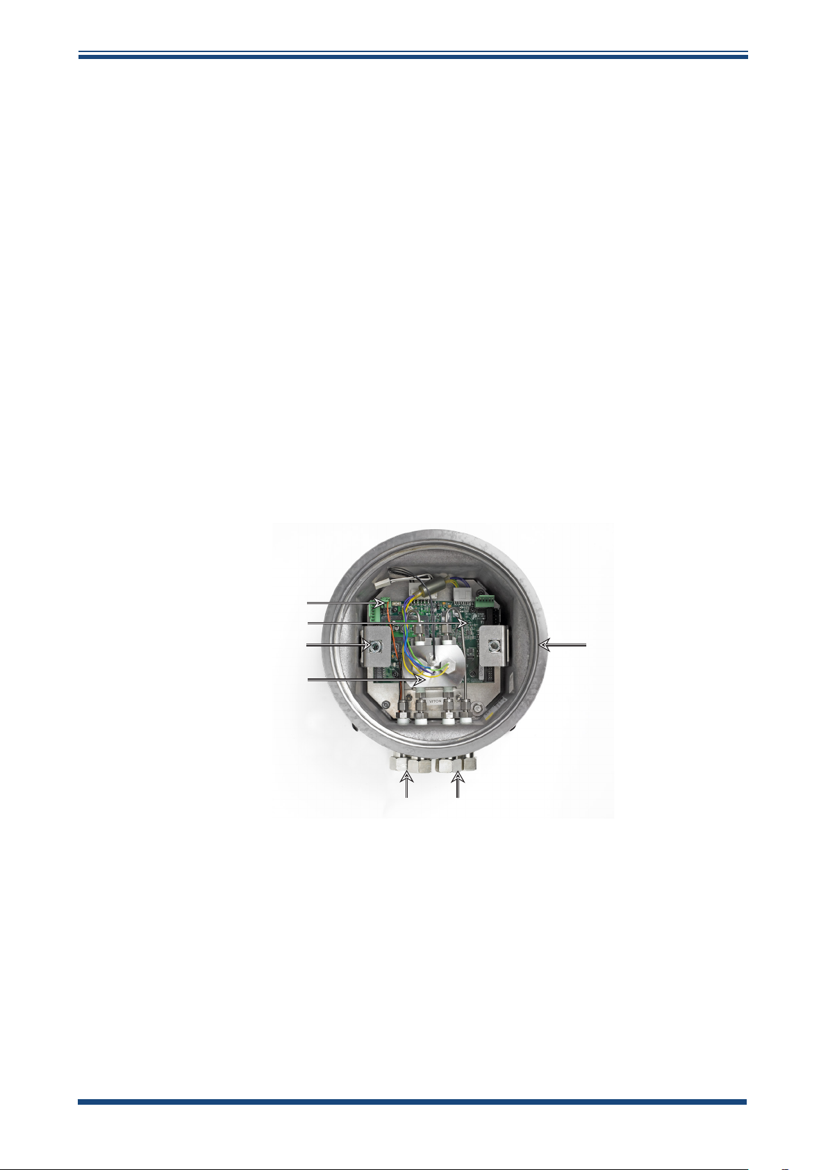
Figure 12
XTC601 Showing Major Components
A Instrument case
B Flowing reference gas inlet and outlet (if fitted)
C Sample gas inlet and outlet
D Measuring cell
E Quick release mechanism for display PCB
F Motherboard
G Power supply (24 V DC) connector (PL9)
Michell Instruments 27
Page 39

INSTALLATION
4.2.1 Casing
• General Purpose (GP) IP66 weather-proof
• Explosion Proof (EX) for installations in hazardous areas, certified to:
XTC601 User’s Manual
II 2 G Ex d IIB+H2 T3 Gb
II 2 D Ex tb IIIC T137°C Db IP66 T amb -40°C to +55°C
cCSAus - Class I, Division 1, Groups B, C, D
TC TR Ex-Cert - 1Exd IIB+H2 T3 Gb
4.3 Set-Up
• The XTC601 is designed to be panel or wall mounted. There are 2 bolt
holes and 2 lugs (1 per corner) see
be found in Appendix B. Mount the analyzer before attempting to remove
the lid.
WARNING: This unit is 24 V DC powered only!
• The EXd thread is greased and therefore it may be advisable to wear latex
gloves.
Figure 11
. Dimensional drawings can
• Ensure that the grub screw is loose, using the hex key (supplied), to
prevent scoring on the casing.
• Connect the earthing strap to the earth point on the right hand side of
the case.
• Remove the lid, using the lid keys (supplied). The lid will require a firm
grip to loosen.
Figure 13
XTC601 Lid Removal
M5 Locking Grub Screw
• If fitted, remove the display / status pcb via the two ¼ turn quick-connect
fittings.
• Disconnect the ribbon / interconnecting cable from the loose pcb.
28 97400 Issue 2, July 2015
Page 40

XTC601 User’s Manual
WARNING: Prior to connecting power, ensure the unit is
correctly earthed via the earth point on the right hand side
• Connect to the power and outputs (see Section 4.5).
• After making all necessary connections, reconnect the display / status pcb
via the ribbon/interconnecting cable & quick-connect fittings and replace
and screw down the lid until fully tight (at least 7 full turns).
• Use the hex key (supplied) to tighten the grub screw. NOTE: This is
necessary in order to adhere to the hazardous area certification
requirements.
• For operating instructions refer to Section 2.
4.4 Mechanical Installation
INSTALLATION
of the case.
WARNING: Unused cable entries must be appropriately
blanked to maintain the integrity of the Exd casing.
There are 3 cable entries on the bottom surface, towards the rear, that can be utilized
by the customer in a variety of manners. The following standard options are available:
Cable Gland, Conduit Entry, Blanking Plug or Light Guide.
Inlet Inlet
Outlet Outlet
Gas
Connections
Cable
Entries
Earthing
Point
Figure 14
XTC601 Gas Connections and Cable Entries
Michell Instruments 29
Page 41

INSTALLATION
4.4.1 Gas Connection Tape
The gas connections are on the bottom surface towards the front of the unit. The
standard fittings are ¼” NPT to ¼” tube. Optional ¼” NPT to 6mm tube adaptors are
available.
concentration is classed as enriched (>21% O2) any
PTFE tape used must be unsintered. This is to prevent
an explosion due to conventional PTFE tape acting as a
Unsintered PTFE tape is available as an accessory from Michell Instruments (PTFETAPE-02).
4.4.2 Sample Gas Requirements
Samples must have a dew point at least 10°C less than the cell temperature (so as not
to condense), be free from oil-mist and with particle size < 3µm. NOTE: There is NO
filtration inside the analyzer.
XTC601 User’s Manual
For Safe Area applications where the oxygen
potential fuel source.
• Sample Inlet Pressure: 0 to 3 barg (0 to 43 psig) with atmospheric vent
• Sample Flow Rate: 100 to 600 ml/min (0.2 to 1.27 scfh)
4.4.3 Calibration Gases
Cylinders of the appropriate Zero and Span gases should be available for installation
and commissioning. Dependent on the specific duty of the analyzer, these gases may
have a lead time of several weeks.
See Section 3 for more information. Contact your local Michell representative for
information on finding a local gas supplier.
30 97400 Issue 2, July 2015
Page 42

XTC601 User’s Manual
4.5 Electrical Installation
4.5.1 Power Supply and Input/Output Signal
The XTC601 requires 24 V DC power input at a maximum start-up current of 1.5 A.
All versions will use a braid screened multi-core cable. Ideally, one cable for signals
(PL4, PL5) and another cable for power (PL9) / relay contacts (PL1). Braid of cables
must be well terminated at the cable glands. Wire sizes should be between 28 to 16
AWG.
The terminal blocks for the power supply, input signal and output signal are located
underneath the lower PCB. NOTE: The terminal blocks are color co-ordinated to
match the connectors - make sure this color coding is adhered to.
Pin1 Pin1
Pin1
PL9 PL4
INSTALLATION
PL5
JMP3
Figure 15
4.5.2 Power Supply (PL9 - Green)
PIN 3 PIN 2 PIN 1
0 V N/C 24 V ±4 V
JMP4
Terminal Block Locations
Pin1
Relays
PL1
4.5.3 Analog Output
Two 4-20mA analog outputs are available. Both are for Thermal Conductivity
concentration. One is fixed on the calibrated range of the unit and the second can
be configured in the menu. NOTE: When the instrument is warming up (cell
temperature not stabilized) these outputs are set to 3.5 mA to indicate that
the instrument is not ready.
• The maximum mA output is approximately 25 mA
• The minimum mA output is approximately 0 mA
Michell Instruments 31
Page 43

INSTALLATION
XTC601 User’s Manual
4.5.4 Serial Output
The analyzer has Modbus RTU communications over RS485 protocol; please see
Application Software CD for more details.
• Type: Modbus RTU over RS485
• RS485: 2 wire (plus ground), half duplex
• Baud Rate: 9600
• Parity: None
• Data bits: 8
• Stop bits: 1
4.5.5 Analog (4-20 mA) Outputs and Communications (PL5 - Green)
PIN 7 PIN 6 PIN 5 PIN 4 PIN 3 PIN 2 PIN 1
RS485
GND
RS485
B
RS485
A
Ch2
O/P
-
Ch2
O/P
+
Ch1
O/P
Ch1
O/P
-
+
NOTE 1: Channel 1 is fixed range output over instrument range and Channel
2 is adjustable within instrument range.
NOTE 2: For long cable lengths, a termination resistor of 120Ω is provided to
aid in impedance matching of the communications cable. This is selectable
via JMP3. A terminating resistor is simply a resistor placed at the extreme
end or ends of a cable on an RS485 network to reduce effects of impedance
mismatch. Impedance mismatch can cause reflections of data as it passes
down the cable and the reflections could be large enough to cause data errors.
4.5.6 Alarm Relay Contacts (PL1- Black)
PIN 6 PIN 5 PIN 4 PIN 3 PIN 2 PIN 1
Hi Alarm
C
Hi Alarm
NO
Hi Alarm
NC
• Type: SPCO (NO, NC and C)
• Contact Rating, Max: 5 A, 250 V
• Hysteresis is 0.03%
Low Alarm
C
Low Alarm
NO
Low Alarm
NC
• AL1 and AL2 can be configured as OFF, LOW or HIGH
• A low alarm switches on when % O
is below the set point and switches
2
off when % O2 is above the set point + Hysteresis
• A high alarm switches on when % O
is above the set point and switches
2
off when % O2 is below the set point - Hysteresis
• When the instrument is warming up (cell temperature not stabilized) both
relays are OFF
32 97400 Issue 2, July 2015
Page 44

XTC601 User’s Manual
4.5.7 Analog (4-20 mA) Inputs and Sensor Excitation Voltage (PL4 - Green)
PIN 6 PIN 5 PIN 4 PIN 3 PIN 2 PIN 1
Ch2
I/P
-
The XTC601 features 2 input channels for 4-20 mA signal from external instruments such
as pressure transmitters or other devices to compensate for pressure or background gas
influence.
CH2
I/P
+
Ch2
Exc.V
Ch1
I/P
-
INSTALLATION
Ch1
I/P
+
Ch1
Exc.V
The input configured as
Parameters Page under the heading
NOTE 1: Channel 1 is External Compensation input and Channel 2 is External
Sensor input.
NOTE 2: Excitation voltage = Same as power supply ±1 V if JMP4 connected
across top 2 pins and 15 ±0.5 V (max 100 mA per channel) if JMP4 connected
across bottom 2 pins.
4.5.8 Light Guide
The optional light guide can be fitted to the left hand cable entry. If this is required for
the Hazardous Area version of the analyzer this must be specified at time of purchase
order. Only one light guide can be fitted to each analyzer.
EXT SENS (External Sensor) can be viewed on the Secondary
EXT I/P (External Input).
If tted in a Hazardous Area version of the XTC601-EX the
light guide MUST NOT be removed by the user. As part of
the certication it is individually pressure tested at the
factory.
Removal and re-tting will invalidate the certication.
Michell Instruments 33
Page 45

APPENDIX A
XTC601 User’s Manual
Appendix A
Technical Specications
34 97400 Issue 2, July 2015
Page 46

XTC601 User’s Manual
Appendix A Technical Specications
Performance
Measurement Technology Thermal Conductivity sensor
Measured Gases CO
Gas Requirements Non-condensing sample with particles <3μm
Measurement Range Selectable from 0-5 up to 0-100%
Display Resolution 0.1%
Display Type Backlit LCD
Intrinsic Error (Accuracy) < ±2% of span *
Response Time (T90) Standard < 20 seconds *
Repeatability ±0.2% of span
Linearity ±1% span
Zero Stability ±0.5% of span per month
Span Stability ±0.5% of span per month
, CH4, Ar, He, N2, H2 or Air
2
APPENDIX A
Sample Flow Rate 100 to 600 ml/min (0.2 to 1.27 scfh) with atmospheric vent
Sample Flow Effect
(cal at 300 ml/min (0.64 scfh))
Sample Pressure 0 to 3 barg (0 to 43 psig)
Sample Temperature 0 to 45°C (+32 to +113°F) max
Sample Cell Temperature Standard +50°C (+122°F)
< 1% of span for flows: 100 to 600 ml/min (0.2 to 1.27 scfh)
Electrical Specications
2 off 4-20 mA inputs
Analog Inputs
Analog Outputs 2 off 4-20 mA outputs (isolated)
Output Ranges
Alarms
Datalogging
Digital Communications Modbus RTU over RS485 Protocol
Power Supply 24 V DC; 1.5 A max
One for an external sensor that can be displayed on the screen
One to act as an active compensation for the process conditions
Primary range is set to the calibrated range of the instrument
The second is user selectable within the primary range
2 off single pole changeover (SPCO) relays for concentration
(250 V, 5 A max)
The user can use the digital communications to log the output
from the analyzer
The unit will store 40 alarm points and the min/max concentrations
with date and time stamp
Operating Conditions
Ambient Temperature
-20 to +55°C (+4 to +131°F)
(dependent on configuration)
Michell Instruments 35
Page 47

APPENDIX A
XTC601 User’s Manual
Mechanical Specication
Warm Up Time < 25 minutes
Stabilization Time 5 minutes
Dimensions 234 x 234 x 172mm (9.2 x 9.2 x 6.7”) (w x d x h)
Weight 9.7kg (21.4lbs)
Wetted Materials 316 stainless steel, boroscillicate glass, platinum, (plus O-ring)
O-Ring Materials Viton, Silicone or Ekraz
Gas Connection
1/4” NPT to 1/4” tube (standard)
1/4” NPT to 6mm tube (optional)
Ingress Protection IP66, NEMA 4
Hazardous Area Classication
ATEX II 2GD Ex d IIB+H2 T3 Gb
Certification Codes
IECEx Ex d IIB+H2 T3 Gb
ITC TR Ex 1Ex d IIB+H2 T3 Gb
cCSAus Class I, Division 1, Groups B C D,
Temperature Ranges for
ATEX and IECEx as per
O-ring type
Silicon: Ta = -40°C to +55°C
Viton: Ta = -15°C to +55°C
Ekraz: Ta = -10°C to +55°C
* The standard intrinsic error and response time will be as above. Certain gas combinations and/or
ranges may have different specifications. Please consult Michell Instruments for specific cases. For
example, CO
/ N2 would be < 50 seconds for T90.
2
NOTE: If the 4 port version is selected then a reference gas with a flow rate of 300ml/
min is required.
Ex tb IIIC T137°C Db IP66
Ex tb IIIC T137°C Db IP66
36 97400 Issue 2, July 2015
Page 48

XTC601 User’s Manual
APPENDIX B
Appendix B
Dimensional Drawings
Michell Instruments 37
Page 49
APPENDIX B
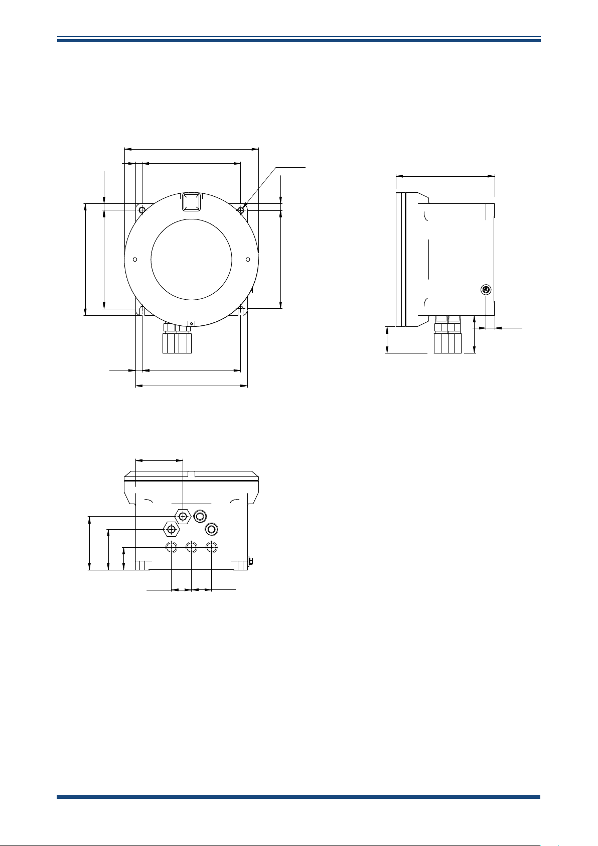
Appendix B Dimensional Drawings
234.0
O
11.5
172.0
O
XTC601 User’s Manual
9.0
172.0
11.5
172.0
195.0
12.0
171.0
195.0
82.5
12.0171.0
15.0
50.5
70.0
93.0
70.5
39.0
35.0
35.0
Figure 16
2 Port Dimensional Drawings
NOTE: Fixing mounts are NOT symmetrical.
This is to ensure correct orientation.
38 97400 Issue 2, July 2015
Page 50

XTC601 User’s Manual
234.0
O
11.5
11.5
172.0
APPENDIX B
O
9.0
12.0
172.0
172.0
195.0
171.012.0
195.0
20.0 30.0 20.0
93.0
70.5
39.0
35.0
35.0
171.0
15.0
50.5
70.0
Figure 17
4 Port Dimensional Drawings
NOTE: Fixing mounts are NOT symmetrical.
This is to ensure correct orientation.
Michell Instruments 39
Page 51

APPENDIX C
XTC601 User’s Manual
Appendix C
Relative Thermal
Conductivity Table
40 97400 Issue 2, July 2015
Page 52

XTC601 User’s Manual
APPENDIX C
Appendix C Relative Thermal Conductivity Table
Gas Temperature=0°C (32°F) Temperature=100°C (212°F)
Commonly Used
Helium, He 5.970 5.530
Hydrogen, H2 6.968 6.803
Water Vapor, H2O 0.755 0.771
Air, N2/O2 1.000 1.000
Nitrogen, N2 1.000 0.989
Oxygen, O2 1.018 1.028
Argon, Ar 0.677 0.665
Carbon Dioxide, CO2 0.603 0.704
Methane, CH4 1.250 1.450
Other Options
1,3 Butadiene, C4H6 0.441 0.642
Acetone, C3H6O 0.406 0.557
Acetylene, C2H2 0.770 0.900
Ammonia, NH3 0.897 1.040
Carbon Monoxide, CO 0.962 0.958
Chlorine, Cl2 0.323 0.340
Cyclohexane, C6H12 0.375 0.576
Ethane, C2H6 0.750 0.970
Ethyl Alcohol, C2H5OH 0.590 0.685
Ethyl Chloride, C2H5Cl 0.391 0.540
Ethylene Oxide, C2H4O 0.469 0.620
Ethylene, C2H4 0.720 0.980
Freon-11, CCl3F 0.286 0.368
Freon-113, C2Cl3F3 0.277 0.369
Freon-12, CCl2F2 0.344 0.442
Freon-22, CHClF2 0.388 0.474
Hydrogen Chloride, HCl 0.520 0.517
Hydrogen Sulfide, H2S 0.538 0.562
Isobutane, C4H10 0.569 0.776
Isopentane, C5H12 0.515 0.702
Isopropyl Alcohol, C3H7OH 0.492 0.644
Methyl Chloride, CH3Cl 0.377 0.530
n-Butane, C4H10 0.552 0.744
Neon, Ne 1.900 1.840
n-Heptane, C7H16 0.399 0.582
n-Hexane, C6H14 0.508 0.662
Nitric Oxide, NO 0.980 0.978
Nitrous Oxide, N2O 0.633 0.762
n-Pentane, C5H12 0.535 0.702
Propane, C3H8 0.615 0.832
Propylene, C3H6 0.626 0.879
Sulfur Dioxide, SO2 0.350 0.381
Vinyl Chloride, C2H3Cl 0.443 0.551
Michell Instruments 41
Page 53

APPENDIX D
XTC601 User’s Manual
Appendix D
Modbus Register Map
42 97400 Issue 2, July 2015
Page 54

XTC601 User’s Manual
APPENDIX D
Appendix D Modbus Register Map
Compatible with XTP601 Firmware Version: V1:03
Addr Function Access Ranges/Resolution Type
0 Modbus Instrument Address (ID) R/W 1-127 A
1 Settings Register R/W 0-65535 B
2 Display Contrast / Brightness R/W 0-100% / 0-100%, 10% steps C
3
4 Chart Interval R/W 2-60 sec, in 2 sec intervals A
5 Spare
6 Alarm 1 (Lo alarm) Set point R/W
7 Alarm 2 (Hi alarm) Set point R/W
8 Range Zero (Ch1 output zero) R 0.00 to Range Span G
9 Range Span (Ch1 output span) R Range Zero to 100.00 G
10 CH1 comp coefficient 20% R/W 0.50-2.00 G
11 CH1 comp coefficient 40% R/W 0.50-2.00 G
12 CH1 comp coefficient 60% R/W 0.50-2.00 G
13 CH1 comp coefficient 80% R/W 0.50-2.00 G
14 CH1 comp coefficient 100% R/W 0.50-2.00 G
15 N2 VCOMP ADC (for ratio comp) R 0-8191 A
16 BACKG VCOMP ADC (for ratio comp) R 0-8191 A
17 BACKG ZERO (for zero offset value) R -10.00-10.00 % G
18 BACKG SPAN (for ratio gas value) R 0.00-100.00 % G
19 BACKG CAL VALUE (for ratio gas value) R 0.00-100.00 % G
20 CH2 Input (Ext Sensor) zero R/W See reg details F
21 CH2 Input (Ext Sensor) span R/W See reg details F
22 Main gas in application R/W 0.6 A
23 Cell Tempr Set point R 40-70 C A
24 PID Proportional Term R 1-20000 A
25 PID Integral Term R 1-500 A
26 PID Derivative Term R 1-100 A
27 Alarm Configuration R/W See reg details L
28 Spare
29 Field Cal Reference 1 R/W
30 Field Cal Actual 1 R/W -199.99-199.99 G
31 Field Cal Reference 2 R/W
32 Spare
33 Spare
34 Language R/W 0-15 A
35 Bridge Pot Wiper Code R 0-1023 A
36 Gain Pot Wiper Code R 0-1023 A
37 Field Cal Actual 2 R/W -199.99-199.99 G
38 Cal Ref1 R 0.00-100.00 G
39 Cal Ref2 R 0.00-100.00 G
Units Register
(Tempr, Pressure, Ext Sens, Param, etc)
R/W See reg details D
Instrum range min
Instrum range max, 0.01
Instrum range min
Instrum range max, 0.01
Instrum range min to Instrum
range max + 20% of range, 0.01
Instrum range min to Instrum
range max + 20% of range, 0.01
G
G
G
G
Michell Instruments 43
Page 55

APPENDIX D
XTC601 User’s Manual
Addr Function Access Ranges/Resolution Type
40 Cal Ref3 R 0.00-100.00 G
41 Cal Ref4 R 0.00-100.00 G
42 Cal Ref5 R 0.00-100.00 G
43 Cal ADC1 R 0-8191 A
44 Cal ADC2 R 0-8191 A
45 Cal ADC3 R 0-8191 A
46 Cal ADC4 R 0-8191 A
47 Cal ADC5 R 0-8191 A
48 mAINPUT1 4mA Cal point R 0-8191 A
49 mAINPUT1 20mA Cal point R 0-8191 A
50 mAINPUT2 4mA Cal point R 0-8191 A
51 mAINPUT2 20mA Cal point R 0-8191 A
52 mAOUTPUT1 4mA Cal point R 0-8191 A
53 mAOUTPUT1 20mA Cal point R 0-8191 A
54 mAOUTPUT2 4mA Cal point R 0-8191 A
55 mAOUTPUT2 20mA Cal point R 0-8191 A
56 CH2 output zero R/W
57 CH2 output span R/W
58 Last Cal Date DATE/MONTH R 1-31/1-12 J
59
60
61 Spare
62 Spare
63 Hours Of Operation R 0-65535 A
64
65 Set Clock HRS W 00-23 J
66 Set Clock MIN W 00-59 J
67 Set Clock DAY W 01-31 J
68 Set Clock MONTH W 01-12 J
69 Set Clock YEAR W 00-99 J
70 % Reading of Gas R -199.00-199.99% G
71 Spare
72 Cell Temperature R -99.9-99.9 or equiv in F or K F
73 PCB temperature (from MSP) R -99 to 99 C or equiv in F or K K
74 Spare
75 mA1 Input in % (comp signal) R 0.0-100.0% F
76 mA2 Input (ext sensor signal) R See Reg Details F
77 Status Flags register R 0-65535 I
78 Clock HOURS/MIN R 00-23 / 00-59 J
79 Clock SEC/DAY R 00-59 / 01-31 J
80 Clock MONTH/YEAR R 01-12 / 00-99 J
81 % MINIMUM (stats) R -199.00-199.99% G
82 % MAXIMUM (stats) R -199.00-199.99% G
Last Cal Date: Field or Factory (bit 15) /
YEAR (bits0-3)
PCB Tempr Offset (for MSP430 Int Tempr
only) – NOT USED in latest f/w
Restore Factory Settings / Cal data
(write 5491 to this reg)
R 0=Factory, 1=Field / 0-99 J
R -100/+100 C K
W 5491 A
Instrum range min to CH2 output
span, 0.01
CH2 output zero to instrum range
max, 0.01
G
G
44 97400 Issue 2, July 2015
Page 56

XTC601 User’s Manual
Addr Function Access Ranges/Resolution Type
83 VCOMP R 0-8191 A
84 Firmware Version R 0.00-200.00 G
85 Live ADC R 0-8191 A
86 Live ADC mA INPUT1 R 0-8191 A
87 Live ADC mA INPUT2 R 0-8191 A
88 Live ADC CellTempr R 0-8191 A
89 Spare
90 Live ADC PCB Tempr R 0-8191 A
91 % without field cal correction R -199.00-199.99% G
92 Spare
93 Spare
94 Spare
95 Spare
96 Spare
97 Spare
98 Spare
99 Spare
APPENDIX D
Register Type A: Unsigned Integer
15 14 13 12 11 10 9 8 7 6 5 4 3 2 1 0
r/w r/w r/w r/w r/w r/w r/w r/w r/w r/w r/w r/w r/w r/w r/w r/w
Unsigned integer. Range = 0 to 65535
Register Type B: Settings
15 14 13 12 11 10 9 8 7 6 5 4 3 2 1 0
r/w r/w r/w r/w r/w r/w r/w r/w r/w r/w r/w r/w r/w r/w r/w r/w
Bit HEX Meaning
0 0001 Field Cal On
1 0002
2 0004 External Compensation On
3 0008 Background Gas Compensation On
4 0010
5 0020 Display Limit 0-100% On
6 0040
7 0080
8 0100
9 0200
10 0400
11 0800
12 1000
13 2000
14 4000
15 8000
Michell Instruments 45
Page 57
APPENDIX D
XTC601 User’s Manual
Register Type C: Display Parameters
15 14 13 12 11 10 9 8 7 6 5 4 3 2 1 0
Display Brightness Display Contrast
r/w r/w r/w r/w r/w r/w r/w r/w r/w r/w r/w r/w r/w r/w r/w r/w
0-100 in 10% steps 0-100 in 10% steps
Register Type D: Units
15 14 13 12 11 10 9 8 7 6 5 4 3 2 1 0
r/w r/w r/w r/w r/w r/w r/w r/w r/w r/w r/w r/w r/w r/w r/w r/w
Bits HEX Meaning (binary)
0, 1 0003 00=degC, 01=degF, 10=K
2, 3 000C Ext press unit, 00 = psia, 01=bara, 10=kPa
4 0010 Field cal type, 0=1 gas (offset), 1=2 gas
5 0020 Date format 0=Non US, 1=US
6 0040 SPARE
7,8,9,10 0780 SPARE
11,12,13 3800
14,15 C000 SPARE
Ext Sensor Parameter (000=none, 001=dewp, 010=tempr,
011=press, 100=other)
Register Type F: -2000.0 to +2000.0
15 14 13 12 11 10 9 8 7 6 5 4 3 2 1 0
r/w r/w r/w r/w r/w r/w r/w r/w r/w r/w r/w r/w r/w r/w r/w r/w
Range = 0 to 40000 represents -2000.0 to +2000.0
Conversion: (RegValue – 20000)/10.0
For external sensor values
Dew point: -100/+20 degC, -148.0/+68.0degC, 173.0/293.0 K
Tempr: -50.0/+100.0 degC, -58.0/+212.0 degF, 223.0/373.0 K
Pressure: 0.0/44.1 psia, 0.0/3.0 barA, 0.0/304.0 kpa
Register Type G: -200.00 to +200.00
15 14 13 12 11 10 9 8 7 6 5 4 3 2 1 0
r/w r/w r/w r/w r/w r/w r/w r/w r/w r/w r/w r/w r/w r/w r/w r/w
Range = 0 to 40000 represents -200.00 to +200.00
Conversion: (RegValue – 20000)/100.00
46 97400 Issue 2, July 2015
Page 58

XTC601 User’s Manual
APPENDIX D
Register Type I - Status/Error
15 14 13 12 11 10 9 8 7 6 5 4 3 2 1 0
r r r r r r r r r r r r r r r r
Bit HEX Meaning Namur LED
0 0001 N/A N/A
1 0002
2 0004 Low alarm ON YELLOW 1 ON
3 0008 High alarm ON YELLOW 2 ON
4 0010
5 0020
6 0040
7 0080
8 0100 NA NA
9 0200
10 0400
11 0800 N/A N/A
12 1000 N/A N/A
13 2000 N/A N/A
14 4000 Instrument is BLIND version (system) N/A
15 8000 N/A N/A
% out of range (beyond calibration range,
e.g. 0-25%)
Ext Comp i/p signal error
(input < 3.6mA or > 21mA)
Ext sens. signal error
(input < 3.6mA or > 21mA)
Cell T not stable
(not within ± 0.15 degC of setpoint for
continuous period of 15 minutes)
Cell T sensor error
(cell tempr measures <-50 or >80°C)
Thermal Conductuvity sensor error
(Vcomp <=1 or >=8191)
PCB tempr too high
(PCB tempr > Cell tempr setpoint)
N/A
RED FLASH
(priority2)
RED FLASH
(priority2)
RED ON
(priority1)
RED ON
(priority1)
RED ON
(priority1)
RED ON
(priority1)
Michell Instruments 47
Page 59

APPENDIX D
XTC601 User’s Manual
Register Type J
15 14 13 12 11 10 9 8 7 6 5 4 3 2 1 0
r/w r/w r/w r/w r/w r/w r/w r/w r/w r/w r/w r/w r/w r/w r/w r/w
eg Day
For reading each 8 bits represents a RTC value. For setting only the lower 8 bits are used for each
RTC value.
Register Type K: -32767 to +32767
15 14 13 12 11 10 9 8 7 6 5 4 3 2 1 0
r/w r/w r/w r/w r/w r/w r/w r/w r/w r/w r/w r/w r/w r/w r/w r/w
eg Month
Range = 0 to 65535 represents values
Conversion: (RegValue – 32767)
Register Type L: Alarm Configuration
15 14 13 12 11 10 9 8 7 6 5 4 3 2 1 0
r/w r/w r/w r/w r/w r/w r/w r/w r/w r/w r/w r/w r/w r/w r/w r/w
Bits Meaning
00 = Alarm1 is Inactive (off)
1, 0
3, 2
01 = Alarm1 is a Low Alarm
10 = Alarm1 is a High Alarm
00 = Alarm2 is Inactive (off)
01 = Alarm2 is a Low Alarm
10 = Alarm2 is a High Alarm
48 97400 Issue 2, July 2015
Page 60

XTC601 User’s Manual
APPENDIX E
Appendix E
Hazardous Area Certication
Michell Instruments 49
Page 61

APPENDIX E
Appendix E Hazardous Area Certication
The XTC601-EX Thermal Conductivity Analyzer is certified compliant to the ATEX
Directive (94/9/EC) and IECEx for use within Zone 1 & 2 Hazardous Areas and has been
assessed so by SIRA Certification (Notified Body 0518).
The XTC601-EX Thermal Conductivity Analyzer is certified compliant to the North
American Standards (USA and Canada) for use within Class I, Division 1, Groups B, C
and D Hazardous Locations and has been assessed so by cCSAus.
E.1 Product Standards
This product conforms to the Standards:
EN60079-0:2012 IEC60079-0:2011
EN60079-1:2007 IEC60079-1:2007
EN60079-31:2009 IEC 60079-31:2008
CSA C22.2 No 0-10 UL 916
CSA C22.2 No 30-M1986 (R 2007) UL 1203
CSA C22.2 No 142-M1987 (R 2009)
XTC601 User’s Manual
E.2 Product Standards
This product is attributed with the product certification codes:
ATEX & IECEx
II 2 GD Ex d IIB+H2 T3 Gb
Ex tb IIIC T137°C Db IP66 T amb -40°C to +55°C
North American
Class I, Division 1, Groups B, C, D
E.3 Global Certicates/Approvals
ATEX SIRA 12ATEX1087X
IECEx IECEx SIR 13.0041X
cCSAus 2609575
TC TR Ex RU C-GB. ГБ05.B.00152
These certificates can be viewed or downloaded from our website at:
http://www.michell.com
E.4 Special Conditions
1. Cable entry holes shall be fitted with either an appropriately certified
cable gland or appropriate certified blanking element. These shall provide
and maintain a minimum enclosure ingress protection of IP66.
2. The maximum pressure associated with the process medium in the
internal pipes shall be limited to 4 bar.
3. The maximum temperature associated with the process medium shall be
limited to 55°C.
50 97400 Issue 2, July 2015
Page 62

XTC601 User’s Manual
E.5 Maintenance and Installation
The XTC601-EX must only be installed by suitably qualified personnel and in accordance
with the instructions provided and the terms of the applicable product certificates.
Maintenance and servicing of the product must only be carried out by suitably trained
personnel or returned to an approved Michell Instruments’ Service Center.
APPENDIX E
Michell Instruments 51
Page 63

APPENDIX F
XTC601 User’s Manual
Appendix F
EU Declarations
52 97400 Issue 2, July 2015
Page 64

XTC601 User’s Manual
Appendix F EU Declarations
F.1 EU Declaration of Conformity - GP Version
APPENDIX F
Michell Instruments 53
Page 65
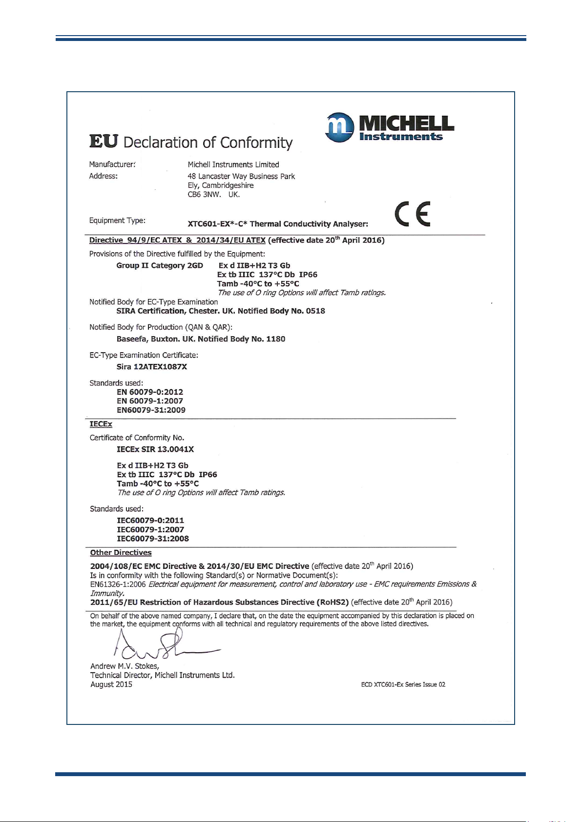
APPENDIX F
F.2 EU Declaration of Conformity - EX Version
XTC601 User’s Manual
54 97400 Issue 2, July 2015
Page 66

XTC601 User’s Manual
APPENDIX G
Appendix G
Quality, Recycling
& Warranty
Information
Michell Instruments 55
Page 67

APPENDIX G
XTC601 User’s Manual
Appendix G Quality, Recycling & Warranty Information
G.1 Pressure Equipment Directive (PED) 97/23/EC
The above Directive has been implemented in United Kingdom Law by the Pressure Equipment
Regulations 1999.
The Regulations require that all pressure equipment and assemblies within the scope of the Pressure
Equipment Directive must be safe when placed on the market or put into service.
Michell Instruments’ products have been assessed and, as referenced against the Classification Charts
detailed in Annex II of the Directive, do not fall into the requirements for CE marking compliance
with the Pressure Equipment Directive.
Article 3, paragraph 3 states that any product containing a pressurized fluid that does not qualify for
compliance should, nevertheless, be constructed with Sound Engineering Practice (SEP).
Michell Instruments attests here that its products have been designed, manufactured & tested to
assure safe operation, and in accordance with Sound Engineering Practices.
G.2 Recycling Policy
Michell Instruments is concerned with the protection of the environment. It is our commitment to
reduce and eliminate from our operations, wherever possible, the use of substances which may be
harmful to the environment. Similarly, we are increasingly using recyclable and/or recycled material
in our business and products wherever it is practical to do so.
To protect natural resources and to promote material reuse, please separate batteries from other
types of waste and recycle responsibly. If batteries are not properly disposed of, these substances
can cause harm to human health and the environment.
The product that you have purchased may contain recyclable and/or recycled parts and we will be
happy to provide you with information on these components if required. For further information
please see the following sections.
G.3 WEEE Compliance
Directive 2012/19/EU 4 July 2012 on Waste Electronic and Electrical Equipment (WEEE)
The Waste Electronic and Electrical Equipment (WEEE) Directive places rules upon European
manufacturers of electrical and electronic equipment. The directives’ aim is to reduce the impact
that electronic devices have on the environment.
Michell Instruments is in full compliance with the WEEE Directive and is registered with an approved
recycler (Registration No. WEE/JB0235YW) and treats the requirement of the directive and the
protection of the environment with the utmost importance. All Michell Instruments’ products are
appropriately marked indicating their requirement for recycling.
It may be required to return certain instruments for treatment at the end of their working life.
Feb 2013
56 97400 Issue 2, July 2015
Page 68

XTC601 User’s Manual
G.4 RoHS2 Compliance
Directive 2011/65/EU of the European Parliament and of the Council of 8 June 2011
The Restriction of Hazardous Substances (RoHS) Directive places rules upon European manufacturers
of electrical and electronic equipment. The directives’ aim is to reduce the impact that electronic
devices have on the environment.
According to the EC Directive 2002/95/EC, Michell Instruments’ products qualify as Category 9,
Control and Monitoring Equipment. Under the 2002/95/EC Directive, Category 9 products are exempt
from compliance with the Directive.
However, the careful design of all Michell Instruments’ products takes into consideration the
requirements of the Directive and, wherever possible, compliance is achieved. All future products
will be developed entirely using compliant materials. Furthermore, Michell Instruments is taking
active steps to remove non-compliant materials and components from existing products wherever
these may occur. Presently, none of the non-compliant materials are known to occur in Michell
Instruments’ products.
APPENDIX G
The new Directive 2011/65/EU (RoHS2) entered into force on 21 July 2011 and required all Member
States to transpose the provisions into their respective national laws by 2 January 2013.
Under the provisions of the RoHS2 EU Directive 2011/65/EU (Article 3, [24]) defines ‘Control and
Monitoring Equipment’ specifically as ‘monitoring and control instruments designed exclusively for
industrial or professional use’.
RoHS2 EU Directive 2011/65/EU states the closing date for compliance of any Control and Monitoring
Equipment product sold into the EU market place as 22nd July 2017.
However, the careful design policy of all Michell Instruments’ products continues to attain compliance
in the shortest practical timescales and strives to ensure that less than 0.1% of total mass per
product, of all non-compliant materials, appear within them. Michell Instruments continues to
monitor suppliers and material sources to ensure that compliance of goods provided is maintained.
January 2013
G.5 Warranty
Unless otherwise agreed, the Supplier warrants that, as from the date of delivery for a period of 12
months, the goods and all their component parts, where applicable, are free from any defects in
design, workmanship, construction or materials.
The Supplier warrants that the services undertaken shall be performed using reasonable skill and
care, and be of a quality conforming to generally accepted industry standards and practices.
Except as expressly stated, all warranties whether express or implied, by operation of law or
otherwise, are hereby excluded in relation to the goods and services to be provided by the Supplier.
All warranty services are provided on a return to base basis. Any transportation costs for the return
of a warranty claim shall reside with the Customer.
Michell Instruments 57
Page 69

APPENDIX G
G.6 REACH Compliance
Regulation (EC) No. 1907/2006
Registration, Evaluation, Authorisation and Restriction of Chemicals (REACH)
Michell Instruments is a manufacturer of moisture measurement and gas analysis instrumentation
and is a ‘downstream’ user of chemicals, as described by the EU Council Directive 76/769/EEC. The
products we supply are not raw chemical products (goods).
Under normal and reasonably foreseeable circumstances of application, the goods supplied to you
shall not contain or release any prohibited chemicals. No listed SVHC (Substances of Very High
Concern) appear within products manufactured by Michell Instruments. Therefore the 0.1% mass
per product, or total usage of 1 tonne/year, will never be exceeded. For these reasons we are neither
required by obligation for registration nor for the creation of material safety data sheets (MSDS) for
our products.
Our continued review of the SVHC Candidate List and latest additions is to ensure we remain
compliant.
XTC601 User’s Manual
Michell Instruments maintains a hazardous material register in which MSDS data sheets are collated,
and we will check that our suppliers will comply to REACH requirements for all materials and
substances we use in the processes of our manufacturing.
In the unlikely event that any chemicals of concern appear in our products in quantities greater than
0.1% of total mass per product we will immediately inform you by correspondence according to the
REACH Article 33 requirements. Our current appraisal is, however, that we do not expect or foresee
such an incidence.
January 2013
G.7 Return Policy
If a Michell Instruments’ product malfunctions within the warranty period, the following procedure
must be completed:
1. Notify a Michell Instruments’ distributor, giving full details of the problem, the
model variant and the serial number of the product.
2. If the nature of the problem indicates the need for factory service then the
instrument should be returned to Michell Instruments, carriage prepaid, preferably
in the original packaging, with a full description of the fault and the customer
contact information.
3. Upon receipt, Michell Instruments will evaluate the product to determine the cause
of the malfunction. Then, one of the following courses of action will be taken:
• If the fault is covered under the terms of the warranty, the
instrument will be repaired at no cost to the owner and returned.
• If Michell Instruments determines that the fault is not covered
under the terms of the warranty, or if the warranty has expired,
an estimate for the cost of the repairs, at standard rates, will be
provided. Upon receipt of the owner’s approval to proceed, the
product will be repaired and returned.
58 97400 Issue 2, July 2015
Page 70

XTC601 User’s Manual
G.8 Calibration Facilities
Michell Instruments’ calibration facilities are among the most sophisticated in the world and have
been recognized for their excellence.
Traceability to the National Physical Laboratory (NPL) UK is achieved through our UKAS Accreditation
(Number 0179). This covers dew point over the range -90 to +90°C (-130 to +194°F) and also
Relative Humidity.
Dew-point calibrations are also traceable to the National Institute for Standards & Technology (NIST)
USA over the range -75 to +20°C (-103 to +68°F).
NOTE: Standard traceable calibration certificates for instruments and sensors are not
issued under our UKAS accreditation.
G.9 Manufacturing Quality
Michell Instruments is registered with the British Standards Institute for Quality Assurance to:
APPENDIX G
BS EN ISO 9001: 2008
Rigorous procedures are performed at every stage of production to ensure that the materials of
construction, manufacturing, calibration and final test procedures meet the requirements laid down
by our BSI approved Quality System.
Please contact Michell Instruments (www.michell.com) if the product does not arrive in perfect
working order.
G.10 FCC (EMC Requirements for North America)
This device complies with part 15 of the FCC Rules. Operation is subject to the following two
conditions:
1. This device may not cause harmful interference.
2. This device must accept any interference, including interference that may cause
undesired operation.
This equipment has been tested and found to comply with the limits for a Class A digital device,
pursuant to part 15 of the FCC Rules. These limits are designed to provide reasonable protection
against harmful interference when the equipment is operated in a commercial environment. This
equipment generates, uses, and can radiate radio frequency energy and, if not installed and used
in accordance with the user manual, may cause harmful interference to radio communications.
Operation of this equipment in a residential area is likely to cause harmful interference in which
case the user will be required to correct the interference at his own expense. This product must be
operated as per the operating instructions provided. Do not make any alterations or modifications
to the product. Any unauthorized alterations or modifications made to this product may require you
to stop operating the product.
Canadian Radio Interference Regulations
This Class A digital product complies with Canadian ICES-001. Règlement canadien sur les
interférences radio. Ce produit numérique de classe A est conforme à la norme NMB-001.
Michell Instruments 59
Page 71

APPENDIX H
XTC601 User’s Manual
Appendix H
Analyzer Return Document
&
Decontamination Declaration
60 97400 Issue 2, July 2015
Page 72

XTC601 User’s Manual
APPENDIX H
Appendix H Analyzer Return Document & Decontamination Declaration
Decontamination Certicate
IMPORTANT NOTE: Please complete this form prior to this instrument, or any components, leaving your
site and being returned to us, or, where applicable, prior to any work being carried out by a Michell
engineer at your site.
Instrument Serial Number
Warranty Repair? YES NO Original PO #
Company Name Contact Name
Address
Telephone # E-mail address
Reason for Return /Description of Fault:
Has this equipment been exposed (internally or externally) to any of the following?
Please circle (YES/NO) as applicable and provide details below
Biohazards YES NO
Biological agents YES NO
Hazardous chemicals YES NO
Radioactive substances YES NO
Other hazards YES NO
Please provide details of any hazardous materials used with this equipment as indicated above (use continuation sheet
if necessary)
Your method of cleaning/decontamination
Has the equipment been cleaned and decontaminated? YES NOT NECESSARY
Michell Instruments will not accept instruments that have been exposed to toxins, radio-activity or bio-hazardous
materials. For most applications involving solvents, acidic, basic, ammable or toxic gases a simple purge with dry
gas (dew point <-30°C) over 24 hours should be sufcient to decontaminate the unit prior to return.
Work will not be carried out on any unit that does not have a completed decontamination declaration.
Decontamination Declaration
I declare that the information above is true and complete to the best of my knowledge, and it is safe for Michell
personnel to service or repair the returned instrument.
Name (Print) Position
Signature Date
F0121, Issue 2, December 2011
Michell Instruments 61
Page 73

NOTES:
XTC601 User’s Manual
62 97400 Issue 2, July 2015
Page 74

http://www.michell.com
 Loading...