

Page 1
Oxygen & Binary Gas Analyzers
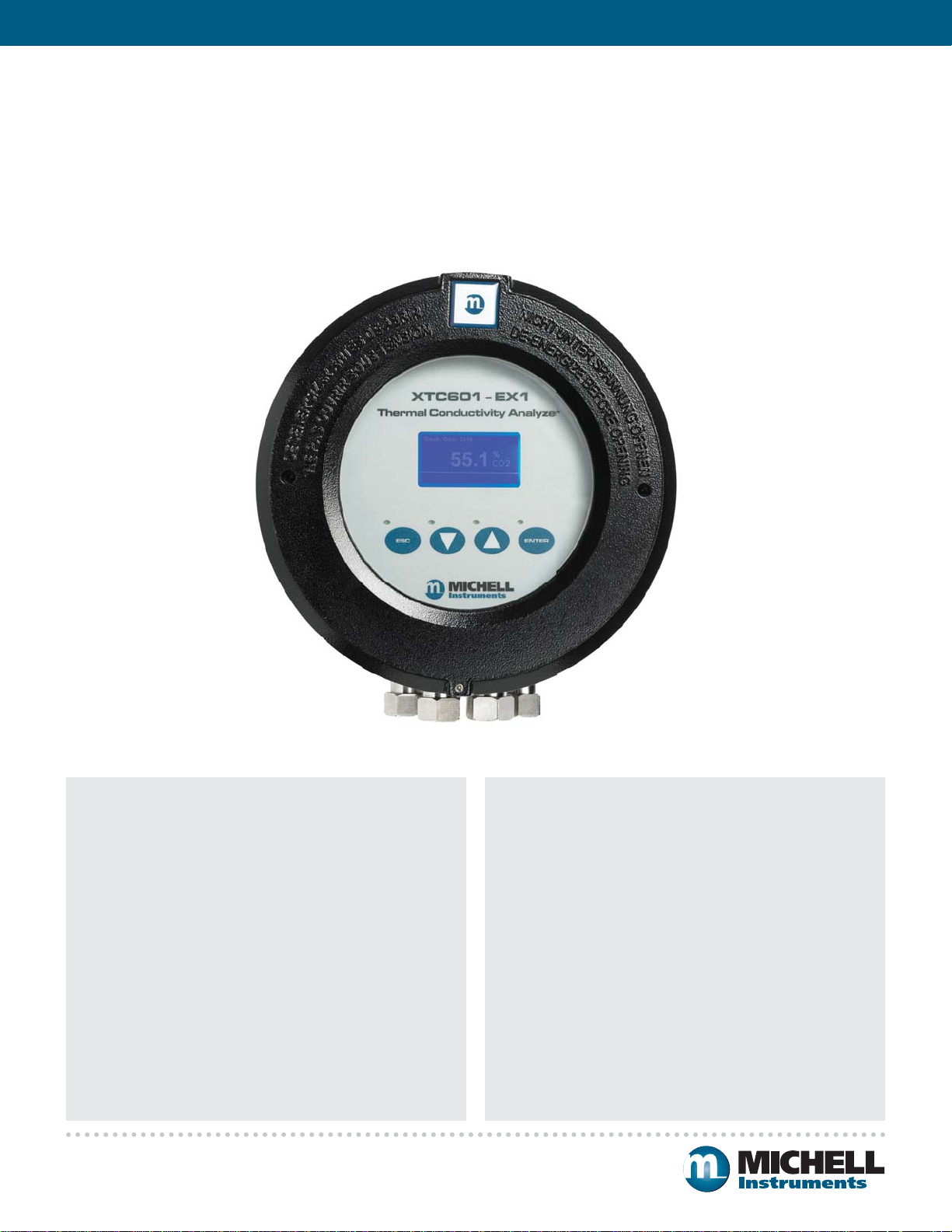
XTC601 Binary Gas Analyzer
Thermal Conductivity Technology in Safe or Hazardous Areas
A robust, linear and stable thermal conductivity analyzer for measurement of binary gas mixes such
as air in hydrogen, nitrogen, argon, helium or carbon-dioxide. The sensor is housed in a rugged
casing, making it suitable for a wide range of applications. When the flame arrestors are fitted, the
analyzer becomes explosion-proof and suitable for hazardous areas.
Highlights
• Suitable for use in ATEX, IECEx, TC TR Ex & CCSAUS
certified Hazardous Areas
• Optional status LEDs following NAMUR standard
• Compact and rugged design with an EExd enclosure and
4-20 mA output
• Touch-screen display allows calibration or adjustment
without the need for a hot works permit
• Accuracy of better than ±2% full scale
• IP66 rated enclosure
• Low cost of ownership due to minimal maintenance
• Ranges available: 0-5 up to 0-100%
• Stability ±0.5% per month (of span)
www.michell.com
Applications
• Hydrogen coolant in electricity turbines
• Product quality in air separation plants
• Syngas production
• Helium recovery
• Fuel cell research
• Gasification
• Product quality such as air in argon for double glazing
• Can be coupled with an XTP601 for measuring oxygen in
varying backgrounds
• Ar or He in food and beverage plants
Page 2
Oxygen & Binary Gas Analyzers
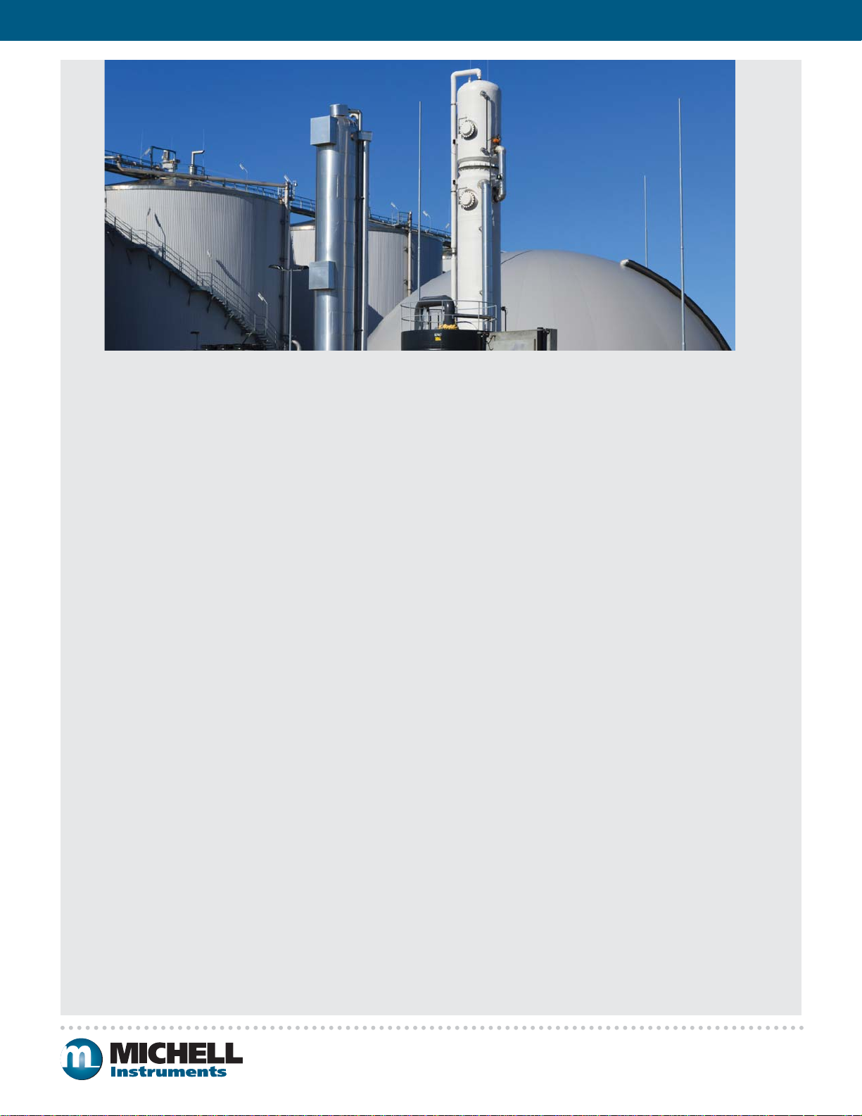
Biogas Plant
Michell XTC601 Thermal Conductivity Analyzer for Safe or
Hazardous Areas
The XTC601 binary gas analyzer is designed to measure the
percentage of a selected gas in a binary mix. Using thermal
conductivity with high quality thermistors, the sensor is
reliable and highly stable. The analyzer is housed in an
explosion-proof case and is rated ATEX Cat II for use in
hazardous areas. For installation in non-hazardous areas, a
general purpose version is available.
Features
High Sensor Stability Reduces Calibration Costs
The sensor in Michell’s XTC601 binary gas analyzer largely
eliminates drift associated with other comparable devices,
improving the stability of the measurement. This allows
longer calibration intervals and reduces both labor and
consumable costs.
Reliable Long-Term Performance
The thermal conductivity sensor has no moving parts, and is
therefore not affected by vibration or movement. This makes
it suitable for offshore and similar installations.
Non-Depleting Technology
The non-depleting sensor technology means that there
is no regular replacement of cells, thus greatly reducing
maintenance time and the cost of ownership. The cell
performance is consistent and does not drift as it is not
consumed by the process.
Easy Installation with Local Display
The XTC601 binary gas analyzer provides two 4-20 mA
outputs and is housed in a robust and weather-proof
casing, allowing the analyzer to be placed at the point of
measurement.
The closer the analyzer can be installed to the sample point,
the better, for many reasons. These include, faster overall
speed of response (for safety), less sample line or cabling
(saves cost) greater choice of installation points (flexibility).
Also having a local display does not require two operators (or
walking back and forth to the control room) for maintenance
or diagnostics.
External Sensor Input
The unit has the facility to accept a 4-20 mA signal from an
external source such as dew point sensor, temperature probe
or user-defined sensor, and display it on the screen. This
saves the cost of buying and installing an external display
for another parameter that only requires occasional visual
inspection.
Technology
Thermal Conductivity Sensor
Thermal conductivity (TC) is a property of all gases. This
can be exploited as each gas has a different TC value and is
used to determine the level of one gas in a binary or pseudobinary mix. Air is a good example of a pseudo binary mix as it
has a fixed proportion of oxygen and nitrogen (both with very
similar thermal conductivities). The analyzer can be supplied
with a fixed or flowing reference.
The XTC601 binary gas analyzer utlizes thermal conductivity
technology to accurately measure one of the two gases
present in the sample. The instrument is very stable which
gives the user confidence in the measurement. This is
important in safety applications such as CO
monitoring.
Measurement Principle
The measuring principle is via matched thermistors in a
Wheatstone Bridge configuration. One thermistor is in the
sample cell and the other is either in a sealed (or flowing)
reference chamber. The whole assembly is heated to +50°C
to ensure an iso-thermal environment. This provides an
accurate and stable platform for measuring the target gas
concentration.
membrane
2/H2
www.michell.com
Page 3

Oxygen & Binary Gas Analyzers
Flexible Packaging
The XTC601 binary gas analyzer is available in three configurations all with the option of Safe (GP) or Hazardous (EX) Area
classification depending on the individual customer's needs. This allows the user to determine the price to feature ratio that best
suits each installation.
XTC601 (EX1 or GP1)
The analyzer provides a local
HMI for the user to access all the
functions of the analyzer through
the glass via capacitance buttons.
As well as displaying the target gas
concentration, there is a status bar
showing messages. The user can
scroll through the front screens to
see a graph of the latest period
(user defined), min and max
values, reading from an external
sensor and alarm history.
XTC601 (EX3 or GP3)
The basic model is a binary gas
analyzer that provides 4-20 mA
outputs, alarm relays & RS485
serial communications. There is
application software included that
allows the user to visualize and
interact with the unit from their
PC or control system. There is
an optional light guide that will
indicate that the unit is powered up
and/or in alarm condition.
XTC601 (EX2 or GP2)
This is similar to the EX3 or GP3
transmitter, but has a window
with power and status LEDs
(alarm and/or fault) following the
NAMUR standard.
Application Software
The XTC601 binary gas analyzer
is supplied with application
software that will allow the user
remote access to the unit. This
includes displaying the target gas
concentration, alarms, graphs,
changing parameters and even
remote calibration.
PS601 Sample Handling System for the XTC601
For a long, trouble-free life, analyzers invariably require a clean, dry gas that is free from particulates and at a suitable temperature
and pressure. In the real world, the process gas to be measured almost never fulfils these requirements. Michell Instruments offers
a complete solution for this problem: The XTC601 and PS601 Sample Handling System. This modular system is constructed in
consultation with customers to ensure the best possible solution for each individual application.
Flow Schematic for CO2 in Bio Gas
BY OTHERS BY MICHELL
CAL GAS INLET
(1/4" OD TUBE
BULKHEAD)
SAMPLE INLET
(1/4" OD TUBE
BULKHEAD)
N2 INLET
(1/4" OD TUBE
BULKHEAD)
COMPRESSED
AIR INLET
(1/4" OD TUBE
BULKHEAD)
BY OTHERSBY MICHELL
NV1
PG1
FM1
FM2
CC1
SV1
F1
LD1
SOV1
ANALYZER
VORTEX TUBE
AIR COOLER
XTC601
OXYGEN
JB1
JB2
NV2
SAMPLE
NV3
BYPASS
DRAIN
NV4
EDUCTOR
POWER SUPPLY
(M20 CABLE GLAND
ENTRY)
OUTPUT SIGNAL
(M20 CABLE GLAND
ENTRY)
SAMPLE OUTLET
(1/4" OD TUBE
BULKHEAD)
AIR VENT
(SILENCER)
The sampling system shown
is for use with “misty” gases
sampled in a hazardous area.
It is one of the more complex
sampling systems available.
The use of an eductor negates
the issues of using a pump
with hydrocarbons and reduces
cost. There is also a vortex
cooler to keep the system
cabinet cool.
www.michell.com
Page 4

Oxygen & Binary Gas Analyzers
Technical Specifications
Performance
Measurement technology Thermal Conductivity sensor
Measured gases CO
, CH4, Ar, He, N2, H2 or Air
2
Gas requirements Non-condensing sample with particles <3μm
Measurement range Selectable from 0-5 up to 0-100%
Display resolution 0.1%
Display type Backlit LCD
Intrinsic error (accuracy) < ±2% of span*
Response time (T90) Standard < 20 seconds*
Repeatability ±0.2% of span
Linearity ±1% span
Zero stability ±0.5% of span per month
Span stability ±0.5% of span per month
Sample flow rate 100 to 600 ml/min
Sample flow effect
(calibrated at 300 ml/
< 1% of span for flows:
100 to 600 ml/min
min)
Sample pressure 0 to 3 barg
Sample temperature 0 to +45°C
Sample cell temperature Standard +50°C
Electrical Specifications
Analog inputs 2 off 4-20 mA inputs
Analog outputs 2 off 4-20 mA outputs
Output ranges Primary range is set to the calibrated range of
Alarms 2 off single pole changeover (SPCO) relays for
Datalogging The user can use the digital communications
*The typical intrinsic error and response time will be as above.
Certain gas combinations and/or ranges may have different specifications.
Please consult Michell Instruments for specific cases. For example, CO2 / N2 would
be < 50 seconds for T90.
One for an external sensor that can be
displayed on the screen
One to act as an active compensation for the
process conditions
the instrument
The second is user selectable within the
primary range
concentration (250 V, 5 A max)
to log the output from the analyzer The unit
will store 40 alarm points and the min/max
concentrations with date and time stamp
Side view (applicable for both models)
172.0
Digital communications Modbus RTU over RS485 Protocol
Power supply 24 V DC; 1.5 A max
Operating Conditions
Ambient temperature -20 to +55°C
(dependent on configuration)
Mechanical Specifications
Warm up time < 30 minutes
Stabilization time 15 minutes
Dimensions 234 x 234 x 172mm (w x d x h)
Weight 9.7 kg
Wetted materials 316 stainless steel, boroscillicate glass,
platinum, (plus O-ring)
O-Ring materials Viton, Silicone or Ekraz
Gas connection 1/4” NPT, 1/4” tube or 6mm tube
Ingress protection IP66, NEMA 4X
Hazardous Area Classification
ATEX II 2GD
IECEx Ex d IIB +H2 T3 Gb
Temperature ranges for
ATEX and IECEx as per
o-ring type
CSA
C
us
TC TR Ex-Cert 1Exd IIB+H2 T3 Gb
Ex d IIB +H2 T3 Gb
Ex tb IIIC T137°C Db IP66
Ex tb IIC T137°C Db IP66
Silicon: Ta = -40°C to +55°C
Viton: Ta = -15°C to +55°C
Ekraz: Ta = -10°C to +55°C
Class I, Division 1, Groups B,C,D
Dimensions
2 port model
93.0
70.5
11.5
11.5
82.5
39.0
35.0
172.0
234.0
35.0
9.0
12.0171.0
4 port model
93.0
70.5
39.0
11.5
11.5
20.0 30.0 20.0
35.0
234.0
172.0
35.0
9.0
12.0
172.0
195.0
15.0
50.5
70.0
12.0
171.0
195.0
Michell Instruments, Inc 319 Newburyport Turnpike, Suite 207, Rowley, MA 01969
Tel: 978 484 0005, Fax: 978 843 7669, Email: us.info@michell.com, Web: www.michell.com/us
Michell Instruments adopts a continuous development programme which sometimes necessitates specification changes without notice.
Issue no: XTC601_97440_V1_US_0414
172.0
195.0
171.012.0
195.0
© 2014 Michell Instruments
171.0
 Loading...