

Page 1

Vapor Delivery System
VDS3
User’s Manual
97433 Issue 1.2
July 2016
Page 2

Please fi ll out the form(s) below for each instrument that has been purchased.
Use this information when contacting Michell Instruments for service purposes.
Instrument
Code
Serial Number
Invoice Date
Location of Instrument
Tag No
Instrument
Code
Serial Number
Invoice Date
Location of Instrument
Tag No
Instrument
Code
Serial Number
Invoice Date
Location of Instrument
Tag No
Page 3
VDS3
For Michell Instruments' contact information please go to
www.michell.com
© 2016 Michell Instruments
This document is the property of Michell Instruments Ltd. and may not be copied or
otherwise reproduced, communicated in any way to third parties, nor stored in any Data
Processing System without the express written authorization of Michell Instruments Ltd.
Page 4

VDS3 User’s Manual
Contents
Safety ................................................................................................................................vi
Electrical Safety ...........................................................................................................vi
Pressure Safety ............................................................................................................vi
Toxic Materials .............................................................................................................vi
Repair and Maintenance ...............................................................................................vi
Safety Conformity ........................................................................................................vi
Abbreviations .....................................................................................................................vii
Warnings ...........................................................................................................................vii
1 INTRODUCTION ................................................................................................1
1.1 Overview ........................................................................................................... 1
2 INSTALLATION ..................................................................................................2
2.1 Enclosure ...........................................................................................................2
2.2 Gas Connections ................................................................................................. 2
2.2.1 Dry Air Inlet .................................................................................................2
2.2.2 Dew-Point Outlet .......................................................................................... 2
2.2.3 Compressed Air ............................................................................................ 2
2.3 Electrical Connections ......................................................................................... 3
2.3.1 Power Supply ...............................................................................................3
2.3.2 PC Control Connection ................................................................................... 3
3 OPERATION ......................................................................................................4
3.1 Filling the Water Container .................................................................................. 4
3.2 'Start-Up' Procedure ............................................................................................4
3.3 Operating Software.............................................................................................5
3.3.1 Dew-Point Control ......................................................................................... 5
3.3.2 Readings ...................................................................................................... 6
3.3.3 Recording ..................................................................................................... 6
4 MAINTENANCE ..................................................................................................8
4.1 Routine ..............................................................................................................8
iv 97433 Issue 1.2, July 2016
Page 5

VDS3 User’s Manual
Figures
Figure 1 Gas Connections .........................................................................................2
Figure 2 PC Control Connection ................................................................................3
Figure 3 Flow Diagram ...........................................................................................12
Figure 4 Set-Up Connection ....................................................................................14
Appendices
Appendix A Technical Specifi cations ..............................................................................10
A.1 General Arrangement ...................................................................11
A.2 Flow Diagram ..............................................................................12
Appendix B Set-Up Software / Adjustment of Setpoints ..................................................14
B.1 Set-Up Connection .......................................................................14
B.2 About the Software ......................................................................14
B.2.1 Initialization ................................................................................15
B.2.2 Manual Setting of Controllers ........................................................16
B.2.3 Programming the VDS ..................................................................19
Appendix C Quality, Recycling & Warranty Information ...................................................21
C.1 Recycling Policy ...........................................................................21
C.2 WEEE And RoHS Compliance ........................................................21
C.3 Manufacturing Quality ..................................................................21
C.4 Calibration Facilities .....................................................................22
C.5 Return Policy ...............................................................................22
C.6 Warranty .....................................................................................22
Appendix D Return Document & Decontamination Declaration ........................................24
Michell Instruments v
Page 6

VDS3 User’s Manual
Safety
The manufacturer has designed this equipment to be safe when operated using the procedures
detailed in this manual. The user must not use this equipment for any other purpose than that
stated. Do not apply values greater than the maximum value stated.
This manual contains operating and safety instructions, which must be followed to ensure the safe
operation and to maintain the equipment in a safe condition. The safety instructions are either
warnings or cautions issued to protect the user and the equipment from injury or damage. Use
qualifi ed personnel and good engineering practice for all procedures in this manual.
Electrical Safety
The instrument is designed to be completely safe when used with options and accessories supplied
by the manufacturer for use with the instrument. The input power supply voltage limits are 220 to
240 V AC OR 100 to 120 V AC 50/60Hz.
Pressure Safety
DO NOT permit pressures greater than the safe working pressure to be applied to the instrument.
The maximum safe inlet pressure is 4.8 barg (70 psig).
Toxic Materials
The use of hazardous materials in the construction of this instrument has been minimized. During
normal operation it is not possible for the user to come into contact with any hazardous substance
which might be employed in the construction of the instrument. Care should, however, be exercised
during maintenance and the disposal of certain parts.
Repair and Maintenance
The instrument must be maintained either by the manufacturer or an accredited service agent. Refer
to www.michell.com for details of Michell Instruments’ worldwide offi ces contact information.
Safety Conformity
This product meets the essential protection requirements of the relevant EU directives.
vi 97433 Issue 1.2, July 2016
Page 7

VDS3 User’s Manual
!
Abbreviations
The following abbreviations are used in this manual:
AC alternating current
atm pressure unit (atmosphere)
barg pressure unit (=100 kP or 0.987 atm) (gauge)
°C degrees Celsius
°F degrees Fahrenheit
dp dew point
EU European Union
Hz Hertz
IEC International Electrotechnical Commission
Nl/min normal liters per minute
mm millimeters
lb pound
psig pound(s) per square inch (gauge)
ppb
scfh standard cubic feet per hour
USB Universal Serial Bus
V Volts
W Watts
" inches
Warnings
The following general warnings listed below are applicable to this instrument. They are
repeated in the text in the appropriate locations.
parts per billion (volume)
V
Where this hazard warning symbol appears in the following
sections, it is used to indicate areas where potentially hazardous
operations need to be carried out.
Michell Instruments vii
Page 8

VDS3 User’s Manual
This page intentionally left blank
viii 97433 Issue 1.2, July 2016
Page 9

VDS3 User’s Manual
1 INTRODUCTION
1.1 Overview
The Michell VDS3 Vapor Delivery System is designed for use as part of a hygrometry
calibration system. It is capable of repeatable generation of set dew-point levels over
the range -100 to +20°C (-148 to +68°F) dew point.
The system is assembled within a small fl oor-mounted 19” equipment rack enclosure
fi tted with castors for ease of movement. The system requires a supply of high quality
dry gas with a moisture content of better than 1 ppbV (-100°C (-148°F) atmospheric
dew point) to enable the maximum range of dew points to be generated. The supply of
high quality dry gas can be provided by a Michell PSD4 Pressure Swing Dryer.
The vapor delivery system divides the dry gas into three controllable gas streams. One
of these streams passes through a controlled evaporator mixer and is then mixed by
volumetric ratios with the other streams to produce different factory pre-set dew point
values over the range -100 to +20°C (-148 to +68°F) (user confi gurable). These dew
points are selected remotely via a PC.
INTRODUCTION
Michell Instruments 1
Page 10

INSTALLATION
2 INSTALLATION
2.1 Enclosure
The instrument enclosure is designed for fl oor mounting (19” equipment mini-rack).
Castors are fi tted for ease of movement.
Access at the front, left hand side and rear is required for operation. Front and side
panels are removable for maintenance & servicing.
2.2 Gas Connections
2.2.1 Dry Air Inlet
The system must be supplied with high quality (oil free) dry compressed air to the same
specifi cation as used during its calibration/setup (< 1ppbV (-100°C (148°F) moisture
content).
The generator was calibrated/set -up using compressed air supplied from a Michell PSD4
Pressure Swing Dryer.
VDS3 User’s Manual
The input gas pressure is further regulated and controlled by an factory set pressure
regulator, located internally. NOTE: This regulator MUST NOT be adjusted!
The gas inlet connection is a stainless steel ¼” Swagelok VCR face seal bulkhead union
fi tting located on the rear panel of the unit marked
2.2.2 Dew-Point Outlet
The gas outlet connection is a stainless steel ¼” Swagelok VCR face seal bulkhead
union fi tting located on the rear panel of the unit marked
2.2.3 Compressed Air
The system requires a separate supply of oil-free compressed air for operating pneumatic
valves and pressurizing the water supply. The compressed air supply can be a normal
industrial compressed air quality (i.e. 5 to 7 barg (72 to 101 psig) @ -40°Cdp (-40°Fdp).
The compressed air inlet connection is a stainless steel 6mm Swagelok
tube fi tting located on the rear panel of the unit marked COMPRESSED AIR INLET.
GAS INLET.
GAS OUTLET.
®
bulkhead union
GAS OUTLET
(1/4” VCR FACE
COMPRESSED AIR
INLET
(6mm TUBE FITTING)
Figure 1
g
g
g
REAR VIEW
Gas Connections
SEAL FITTING)
GAS INLET
(1/4” VCR FACE
SEAL FITTING)
2 97433 Issue 1.2, July 2016
Page 11
VDS3 User’s Manual
2.3 Electrical Connections
2.3.1 Power Supply
100 to 120 V AC OR 220 to 240 V AC 50/60Hz power supply is required to operate this
instrument. Refer to the yellow label located on the rear panel of the unit for the correct
supply voltage required.
The power supply connection is via the 3-pin IEC fused plug located on the rear panel
of the unit. A 3 core power cable is provided, the free end of which should be wired to
a suitable earthed plug or directly via a fused power spur.
Power cable conductors are colored according to the convention:
Brown L (Live)
Blue N (Neutral)
Green/Yellow E (Earth/Ground)
INSTALLATION
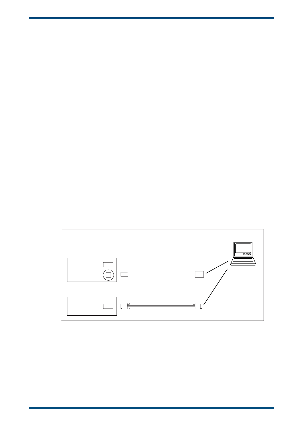
2.3.2 PC Control Connection
Connect the host PC to the VDS via a USB connector located on the rear panel of the
unit marked
PC (CONTROL). A 3 meter USB cable assembly is provided and should be
connected as shown below:
VDS3
RS485 (SET UP)
PC (CONTROL)
S4000 Dewpointmeter
RS232
USB Cable
Serial Cable
Connect to spare
USB port
Host PC
g
g
Connect to spare
COMM Serial port
Figure 2
PC Control Connection
NOTE: Ensure that the S4000 Dewpointmeter is connected to the host PC to
enable the software to read and record dew points. If it is not connected the
software will not operate correctly.
Michell Instruments 3
Page 12

OPERATION
!
3 OPERATION
Before operation, the system needs to be fi lled with distilled water.
3.1 Filling the Water Container
This unit operates under pressure. Safety goggles should be
worn when fi lling the water container.
NOTE: Before attempting fi lling and subsequent top-ups, while the unit is
in operation, ensure that the water container is isolated by turning off the
water pressure valve (¼-turn clockwise) located alongside the display on the
front panel.
1. Remove the side panel to access the water container.
2. Slowly turn the big blue valve handle (¼-turn anti-clockwise) to release
the air pressure within the container.
VDS3 User’s Manual
3. Fill with clean distilled water to the level of the fi ller port (water capacity
is approximately 1 liter (1 quart).
4. Turn the big blue valve handle back to seal-off the water container.
5. Slowly turn on the water pressure valve (¼-turn anti-clockwise) located
alongside the display on the front panel to repressurize the water container .
NOTE: When fi lling for the fi rst time, or if the water was allowed to
run out, slowly unscrew the tube nut on top of the CEM (Controlled
Evaporation Mixer) to remove any airlock in the system and retighten the nut.
6. Replace the side panel.
3.2 'Start-Up' Procedure
NOTE: If a sequence of dew points is required it is important to start at the
driest and select progressively through the range, moving from dry to wet.
1. Ensure that the water container is fi lled with distilled water as described
above and that the compressed air and dry air supplies are present.
2. Switch on the system via the front panel
panel display should show
fi rmware version and mm/yy is the date) and
POWER on/off switch. The front
VDS Vx.x mm/yy cal mode (where Vx.x is the
Set dewpoint: -100.0.
3. Allow the system to operate for a minimum of 1 hour so that the system
pipework can purge and stabilize.
4. When operating for the fi rst time, or after a long period without use, the
system should be purged for longer, ie a minimum of 8 hours/overnight.
A 5-day purge is required before using the system below -80°Cdp
(-112°Fdp).
NOTE: When the sequence is complete ALWAYS return the unit to the
setting and allow the system to run for several minutes to purge out any
moist gas before shut down.
4 97433 Issue 1.2, July 2016
-100.0
Page 13

VDS3 User’s Manual
3.3 Operating Software
3.3.1 Dew-Point Control
Before starting up the PC, ensure that the dew-point control USB cable and the reference
hygrometer serial cable are both connected to it. Start up the PC and the VDS interface
software will load automatically.
Dew points may be selected manually via a keypad, or a sequence of user-defi ned dew
points (for user-defi ned durations) may be run automatically via a profi le table.
NOTE: The VDS interface software does not control the reference hygrometer
sensor head temperature. The head temperature must be controlled manually.
NOTE: On launch the software will be in manual mode.
Manual Control (keypad):
OPERATION
Click the buttons to select a dew point.
NOTE: The VDS display shows the currently selected
dew point.
Automatic Control (profi le table):
In automatic mode the software will step through the profi le
table starting at position 1 and ending at position 13.
The table is fully customizable. Dew points and durations
may be changed as required.
Table profi les may be saved and loaded.
NOTE: Dew points must be between -100 and +20 in
10 degree steps.
NOTE: If a duration is entered as 0 hours and 0
minutes, the position will be skipped.
Michell Instruments 5
Page 14

OPERATION
3.3.2 Readings
The Readings Section displays both the current set dew point and the actual dew point
as read from the reference hygrometer.
NOTE: The reference hygrometer is read approximately every second.
Readings Section:
Actual dew point as measured by the reference hygrometer.
Set dew point displays the dew point as set through either
manual or automatic dew-point selection.
VDS3 User’s Manual
3.3.3 Recording
The Recording Section contains a real-time chart recorder and a history canvas.
The chart recorder plots both set and actual dew points, plotting new readings
approximately every 5 seconds.
Above the chart are four chart controls, namely;
Plot puts the chart into plot (normal) mode
•
Scroll-X puts the chart into a mode which allows the X axis to be scrolled
•
left and right
Scroll-Y puts the chart into a mode which allows the Y axis to be scrolled
•
up and down
Zoom box puts the chart into a mode which allows zooming in on an area
•
of the chart
To use these modes, click the desired control button then click and drag the mouse on
the chart area.
Plot, Scroll-X, Scroll-Y and Zoom box.
To use the Zoom box, click the left mouse button on the chart area. Keeping the left
mouse button held down, drag a box around the area to be zoomed.
NOTE: After using any mode, click
Plot to resume normal plotting.
6 97433 Issue 1.2, July 2016
Page 15

VDS3 User’s Manual
The history canvas records and displays the following events:
• Any set dew-point changes that take place (either manually or
automatically). Automatic changes are prefi xed with the text (
Manual changes do not have a prefi x.
• When an automatic profi le is started and fi nished.
NOTE: On launch the software will not be recording.
OPERATION
Auto) and
To record, click the
RECORDING button.
Recording Section:
Chart Controls
History Canvas
Chart Area
Recording Controls
START RECORDING button. To stop recording, click the STOP
Michell Instruments 7
Page 16

MAINTENANCE
!
4 MAINTENANCE
4.1 Routine
Routine maintenance of the Michell VDS3 Vapor Delivery System is limited to checking
that the water container is always fi lled with distilled water (refer to Section 3.1).
This should be checked weekly (or more frequently if high dew points are generated for
long periods).
VDS3 User’s Manual
WARNING:
This unit operates under pressure. It is recommended that
safety goggles are worn.
8 97433 Issue 1.2, July 2016
Page 17

VDS3 User’s Manual
APPENDIX A
Appendix A
Technical Specifi cations
Michell Instruments 9
Page 18

APPENDIX A
VDS3 User’s Manual
Appendix A Technical Specifi cations
General
-100 to +20°C
Dew-Point Range
Output Stability ±0.5ºC (±0.9ºF)
Gas Supply
Gas Output 10 Nl/min @ 0.4 barg
Cable Connection
Water Container
Power Supply 220 to 240 V AC OR 100 to 120 V AC, 50/60Hz
Power Consumption 500 W maximum
Power Connector 3 pin IEC
Power Supply Fuse 3A (F) quick blow
Operating Temperature +10 to +40°C (+50 to +104°F)
Construction Painted diecast aluminum enclosure with smoked glass door
Dimensions 1020 x 555 x 600mm (40 x 21.8 x 23.6") (h x w x d)
Weight 65kg (143lbs) maximum
(factory default pre-set values:
–100, -90, -80, -70, -60, -50, -40, -30, -20, -10, 0, +10 and +20°C)
30 Nl/min @ 4.8 barg (70 psig) pressure and less than 13.8ppb
(-100°C (-148°F) atmospheric dew point) moisture content
USB (type B) for PC Control
RS485 (9 way D plug) for set-up
Material: ABS
Water capacity: 1 liter (1 quart)
V
10 97433 Issue 1.2, July 2016
Page 19

VDS3 User’s Manual
A.1 General Arrangement
APPENDIX A
h
(40.2”)
1020mm
553mm X (600mm depth)
g
(21.7”) X (23.6” depth)
VDS-3
Vapour Delivery System
g
g
g
g
h
WATER PRESSURE
ON/OFF VALVE
POWER ON/OFF
SWITCH
DEW-POINT
SET POINT
DISPLAY
TEMPERATURE
CONTROLLER
(BEHIND PANEL)
COMPRESSED AIR
INLET
(6mm TUBE FITTING)
RS485 CONNECTOR
(9 WAY D TYPE)
PC CONTROL
(USB PORT)
g
FRONT VIEW
g
g
g
g
REAR VIEW
g
g
g
g
CASTORS
WATER
CONTAINER
FILLING PORT
(BEHIND SIDE PANEL)
GAS OUTLET
(1/4” VCR FACE
SEAL FITTING)
GAS INLET
(1/4” VCR FACE
SEAL FITTING)
230 V AC POWER
CONNECTOR
(3 A FUSED)
Michell Instruments 11
Page 20

APPENDIX A
A.2 Flow Diagram
GAS OUTLET
INSTRUMENTS
TO S4000 AND
ON TEST
CV2
VENT
CV1
VENT
EPC2
COIL
4 X 100mm
VDS3 User’s Manual
GFC4
GAUGE
PRESSURE
PORT
FILLER
BALL
EPC1
CEM
LFM GFC1
VALV E
WATER
CONTAINER
BALL
VALV E
PRESSURE
REGULATOR
SOV1
GFC2
MIXING
CHAMBERS
TO CV1
TO CV2
SOV2
GFC3
GFC5
PRESSURE
SWING DRYER
PSD4 PRESSURE
GAS INLET FROM
REGULATOR
Figure 3
PRESSURE
AIR SUPPLY
COMPRESSED
7 BARG & -40ºCdp
REGULATOR
Flow Diagram
12 97433 Issue 1.2, July 2016
Page 21

VDS3 User’s Manual
APPENDIX B
Appendix B
Set-Up Software /
Adjustment of Setpoints
Michell Instruments 13
Page 22

APPENDIX B
VDS3 User’s Manual
Appendix B Set-Up Software / Adjustment of Setpoints
The system is supplied pre-set with 13 setpoints between -100 and +20 at 10 degree
intervals. However, if different setpoints are required, please follow the instructions
below.
B.1 Set-Up Connection
Connect the host PC to the VDS via the 9-way D type connector located on the rear
panel of the unit marked
with a digital interface converter, is provided and should be connected as shown below:
RS485 (SETUP). A 2 meter grey serial cable assembly, along
Host PC
VDS3
RS485 (SET UP)
PC (CONTROL)
B.2 About the Software
Before launching the set-up software, the VDS system must be placed in set-up mode
by following the steps below:
1. Shut down all software(s) running on the host PC.
2. Launch the VDS utility program (found in the host PC desktop VDS folder).
3. Enter
4. Click the
1 as the comm port number and then click the Connect button.
Setup mode button.
Figure 4
Serial Cable
Set-Up Connection
KK-ADE
Converter
RS485
RS232
g
Connect to spare
COMM Serial port
The VDS display should now show
If not, click the
Setup mode button again. When the VDS display shows Setup mode
Setup mode.
close the utility program.
Launch the set-up software through
START > Programs > Michell Instruments >
VDS Setup software > VDS Setup software Vx.x.
The software is used to establish fi xed, repeatable dew points through on-screen,
manual adjustments of all system controllers. Once dew points have been established,
the settings are uploaded to, stored and used by the VDS control unit in dew-point
generation mode.
Up to 13 fi xed dew points may be stored by the VDS control unit, normally –100 to +20
in 10 degree steps.
14 97433 Issue 1.2, July 2016
Page 23

VDS3 User’s Manual
The software provides:
1. A manual settings window
Where individual controller positions & valve states may be set manually in
order to establish dew points.
2. A system diagram window
Where manual controller settings (targets) and actual controller settings
(read back from the controllers) may be viewed simultaneously (useful for
diagnostic purposes).
3. A system settings window
This window has 3 purposes, namely:
i. It contains the table of settings stored within the control
unit (these settings are stored in a text fi le at c:/Massfl ow.
dat) and may be saved / loaded at any time.
ii. Settings may be transferred from the table into the manual
settings window.
APPENDIX B
iii. The control unit is programmed with the table of settings
through this window.
B.2.1 Initialization
On launching the software, a communications port input box appears as shown below:
Enter 1 (for COMM port number 1) and click OK.
Michell Instruments 15
Page 24

APPENDIX B
B.2.2 Manual Setting of Controllers
Use the Control panel window to manually set all gas, pressure and liquid fl ow controller
inputs.
This enables a specifi c dew point to be generated if required, e.g. to generate -25°C,
load the -30°C preset and adjust the values as appropriate.
Position the scroll bars to the desired
levels and set the valves to on/off by
toggling the valve buttons.
Combinations of valve positions make up
3 stages (Stage 1, 2 and 3) as shown
next to the buttons.
VDS3 User’s Manual
Once the desired settings are made,
click the Program button to upload
the settings to the VDS controller. The
software will prompt for programming
confi rmation.
NOTE: These are live settings only
and are NOT stored by the VDS
control unit.
After a few seconds, the status bar at the bottom of the screen should indicate that the
VDS control unit has been programmed successfully. Also, the S
will appear showing the manually set values next to each controller.
NOTE: The VDS front panel display will show
while manual settings are being made.
Set dewpoint: USER on the display
ystem Diagram window
16 97433 Issue 1.2, July 2016
Page 25

VDS3 User’s Manual
APPENDIX B
Status Bar
A success message on the bottom of the
screen shows that the controller inputs have
been set as per the manual settings.
To read back from the controller's outputs, tick the
box (bottom left of the system diagram window). The controller readings will update
every few seconds.
NOTE: This is a useful visual tool for diagnostics purposes of the system,
confi rming that all components of the system are functioning properly.
System Diagram Window
T arget values map the manually-set values in
the control panel. Both the system diagram
and the Controller input are updated with
these values by clicking the
in the Control panel window.
Program button
Continuously read system check
Michell Instruments 17
Page 26

APPENDIX B
VDS3 User’s Manual
Feedback
Values alongside
correctly, these values should match the target values.
(The screen shot shows random numbers for illustration purposes only).
NOTE: If the target EPC is set to 0 then a slight deviation may be observed due
to back-pressure in the system.
Reads text are values being read back from the controllers. If functioning
18 97433 Issue 1.2, July 2016
Page 27

VDS3 User’s Manual
B.2.3 Programming the VDS
NOTE: The settings have been factory set at Michell Instruments prior to
shipment. However, if you want to change them proceed as follows:
Once all dew points have been established, the controller settings must be entered into
the System settings table and then programmed into the control unit.
The screen shot below is an example of a full 13 point table from –100 to +20 in 10°C
steps.
APPENDIX B
System Settings
The table shows example dew points and associated controller
settings by row.
Values may be edited by clicking on a cell and typing. Use backspace to erase digits.
Toggle valve states by double-clicking the valve cells.
Click
Save to save the table to disk or Load to load it from disk. The fi le is located at:
c:/Massfl ow.dat.
To program the VDS with the table, click
a minute. (The software will inform whether the programming has been successful or
not). Once programmed, the VDS control unit is ready to run in calibration mode on
next power down / power up.
The dew points are mapped in order as per the settings table, i.e. a binary value of 0000
on the D.C.L. input will select the dew point at position 1 (-100 in the above example),
0001 at position 2 (-90) to 1101 at position 13 (+20) and so on.
NOTE: Adjusting the values in this table will not change the keypad labels
shown in Section 3.3.1, but will change the generated dew-points.
Program Eeprom. This process takes about
Michell Instruments 19
Page 28

APPENDIX C
VDS3 User’s Manual
Appendix C
Quality, Recycling
& Warranty
Information
20 97433 Issue 1.2, July 2016
Page 29

VDS3 User’s Manual
Appendix C Quality, Recycling & Warranty Information
C.1 Recycling Policy
Michell Instruments is concerned with the protection of the environment. It is our
commitment to reduce and eliminate from our operations, wherever possible, the use
of substances which may be harmful to the environment. Similarly, we are increasingly
using recyclable and/or recycled material in our business and products wherever it is
practical to do so.
To protect natural resources and to promote material reuse, please separate batteries
from other types of waste and recycle responsibly. If batteries are not properly disposed
of, these substances can cause harm to human health and the environment
The product that you have purchased may contain recyclable and/or recycled parts and
we will be happy to provide you with information on these components if required.
APPENDIX C
C.2 WEEE And RoHS Compliance
The Waste Electronic and Electrical Equipment (WEEE) Directive, and the Restriction
of Hazardous Substances (RoHS) Directive place rules upon European manufacturers
of electrical and electronic equipment. The directives’ aim is to reduce the impact that
electronic devices have on the environment.
Michell products are currently exempt from the RoHS directive, however all future
products will be developed entirely using compliant materials. Furthermore, Michell is
taking active steps to remove non-compliant materials and components from existing
products wherever possible.
Michell is in full compliance with the WEEE Directive (Registration No . WEE/JB0235YW).
Customers may be required to return certain instruments for treatment at the end of
their working life.
June 2010
C.3 Manufacturing Quality
Michell Instruments is registered with the British Standards Institute for Quality
Assurance to:
BS EN ISO 9001: 2008
Rigorous procedures are performed at every stage of production to ensure that the
materials of construction, manufacturing, calibration and fi nal test procedures meet the
requirements laid down by our BSI approved Quality System.
Please contact Michell Instruments (www.michell.com) if the product does not arrive in
perfect working order.
Michell Instruments 21
Page 30

APPENDIX C
C.4 Calibration Facilities
Michell Instruments’ calibration facilities are among the most sophisticated in the world
and have been recognized for their excellence.
Traceability to the National Physical Laboratory (NPL) UK is achieved through our UKAS
Accreditation (Number 0179). This covers dew point over the range -90 to +90°C (-130
to +194°F) and also Relative Humidity.
Dew-point calibrations are also traceable to the National Institute for Standards &
Technology (NIST) USA over the range -75 to +20°C (-103 to +68°F).
NOTE: Standard traceable calibration certifi cates for instruments and sensors are not
issued under our UKAS accreditation. UKAS certifi cates are usually to special order and
are clearly identifi ed.
C.5 Return Policy
If a Michell Instruments’ product malfunctions within the warranty period, the following
procedure must be completed:
VDS3 User’s Manual
1. Notify a Michell Instruments’ distributor, giving full details of the problem,
the model variant and the serial number of the product.
2. If the nature of the problem indicates the need for factory service then the
instrument should be returned to Michell Instruments, carriage prepaid,
preferably in the original packaging, with a full description of the fault
and the customer contact information.
3. Upon receipt, Michell Instruments will evaluate the product to determine
the cause of the malfunction. Then, one of the following courses of action
will be taken:
• If the fault is covered under the terms of the warranty, the
• If Michell Instruments determines that the fault is not covered
C.6 Warranty
Unless otherwise agreed, the Supplier warrants that as from the date of delivery for a
period of 12 months the goods and all their component parts, where applicable, are free
from any defects in design, workmanship, construction or materials.
instrument will be repaired at no cost to the owner and returned.
under the terms of the warranty, or if the warranty has expired,
an estimate for the cost of the repairs, at standard rates, will be
provided. Upon receipt of the owner’s approval to proceed, the
product will be repaired and returned.
The Supplier warrants that the services undertaken shall be performed using reasonable
skill and care, and of a quality conforming to generally accepted industry standards and
practices.
Except as expressly stated all warranties whether express or implied, by operation
of law or otherwise, are hereby excluded in relation to the goods and services to be
provided by the Supplier.
All warranty services are provided on a return to base basis. Any transportation costs
for the return of a warranty claim shall reside with the Customer.
22 97433 Issue 1.2, July 2016
Page 31

VDS3 User’s Manual
APPENDIX D
Appendix D
Return Document
&
Decontamination Declaration
Michell Instruments 23
Page 32

APPENDIX D
VDS3 User’s Manual
Appendix D Return Document & Decontamination Declaration
'HFRQWDPLQDWLRQ&HUWL¿FDWH
IMPORTANT NOTE: Please complete this form prior to this instrument, or any components, leaving your
site and being returned to us, or, where applicable, prior to any work being carried out by a Michell
engineer at your site.
Instrument Serial Number
Warranty Repair? YES NO Original PO #
Company Name Contact Name
Address
Telephone # E-mail address
Reason for Return /Description of Fault:
Has this equipment been exposed (internally or externally) to any of the following?
Please circle (YES/NO) as applicable and provide details below
Biohazards YES NO
Biological agents YES NO
Hazardous chemicals YES NO
Radioactive substances YES NO
Other hazards YES NO
Please provide details of any hazardous materials used with this equipment as indicated above (use continuation sheet
if necessary)
Your method of cleaning/decontamination
Has the equipment been cleaned and decontaminated? YES NOT NECESSARY
Michell Instruments will not accept instruments that have been exposed to toxins, radio-activity or bio-hazardous
PDWHULDOV)RUPRVWDSSOLFDWLRQVLQYROYLQJVROYHQWVDFLGLFEDVLFÀDPPDEOHRUWR[LFJDVHVD VLPSOHSXUJHZLWKGU\
JDVGHZSRLQW&RYHUKRXUVVKRXOGEHVXI¿FLHQWWRGHFRQWDPLQDWHWKHXQLWSULRUWRUHWXUQ
Work will not be carried out on any unit that does not have a completed decontamination declaration.
Decontamination Declaration
I declare that the information above is true and complete to the best of my knowledge, and it is safe for Michell
personnel to service or repair the returned instrument.
Name (Print) Position
Signature Date
F0121, Issue 2, December 2011
24 97433 Issue 1.2, July 2016
Page 33

VDS3 User’s Manual
NOTES:
Michell Instruments 25
Page 34

http://www.michell.com
 Loading...