

Page 1

OptiPEAK TDL600
Process Moisture Analyzer
User’s Manual
97319 Issue 4.2
November 2018
Page 2

Please fi ll out the form(s) below for each instrument that has been purchased.
Use this information when contacting Michell Instruments for service purposes.
Analyzer
Code
Serial Number
Invoice Date
Location of Instrument
Tag No
Analyzer
Code
Serial Number
Invoice Date
Location of Instrument
Tag No
Analyzer
Code
Serial Number
Invoice Date
Location of Instrument
Tag No
Page 3
OptiPEAK TDL600
For Michell Instruments' contact information please go to
www.michell.com
© 2018 Michell Instruments
This document is the property of Michell Instruments Ltd. and may not be copied or
otherwise reproduced, communicated in any way to third parties, nor stored in any Data
Processing System without the express written authorization of Michell Instruments Ltd.
Page 4

OptiPEAK TDL600 User’s Manual
Contents
Safety ...............................................................................................................................vii
Electrical Safety ..........................................................................................................vii
Pressure Safety ........................................................................................................... vii
Toxic Materials ............................................................................................................vii
Repair and Maintenance ..............................................................................................vii
Calibration (Factory Validation) ..................................................................................... vii
Safety Conformity .......................................................................................................vii
Abbreviations .................................................................................................................... viii
1 INTRODUCTION ................................................................................................1
1.1 Application ......................................................................................................... 1
1.2 Features ............................................................................................................ 1
1.3 Theory of Operation ........................................................................................... 2
1.3.1 Measurement Using a Laser ........................................................................... 4
2 INSTALLATION ..................................................................................................6
2.1 Unpacking the Instrument ................................................................................... 6
2.2 Lifting and Handling ........................................................................................... 7
2.3 Laser Safety ....................................................................................................... 7
2.4 Hazardous Area Safety ........................................................................................ 8
2.5 Electrical Safety .................................................................................................. 9
2.5.1 Equipment Ratings and Installation Details ...................................................... 9
2.6 Pressure Safety ................................................................................................ 11
2.7 Basic Installation Guidelines .............................................................................. 11
2.8 Electrical Connections ....................................................................................... 15
2.8.1 Power Connection ....................................................................................... 15
2.8.2 Analog Outputs ........................................................................................... 16
2.8.3 Analog Inputs ............................................................................................. 16
2.8.4 Alarm Relays............................................................................................... 16
2.8.5 Modbus RTU / RS485 Connection ................................................................. 17
2.9 Environmental Requirements ............................................................................. 17
2.10 Sample Conditioning Requirements .................................................................... 18
2.10.1 Gas Connections ......................................................................................... 18
2.10.2 Sample Flow Gas Handling Components ....................................................... 18
2.11 Options ............................................................................................................ 21
2.11.1 Enclosure Heater Temperature Control (Outdoor systems ONLY) ..................... 21
2.11.2 Vortex Cooling (Outdoor systems ONLY) ....................................................... 21
2.11.3 Trace Heated Sample Line ........................................................................... 21
3 OPERATION ....................................................................................................22
3.1 Start-Up Procedure ........................................................................................... 22
3.2 Shut Down Procedure ....................................................................................... 23
3.3 User Interface .................................................................................................. 24
3.3.1 Interface Controls ....................................................................................... 24
3.3.2 ‘Up/Down Arrow’ Keys ................................................................................. 24
3.3.3 ‘ENTER’ Key ................................................................................................ 25
3.3.4 ‘ESC’ Key .................................................................................................... 25
3.4 Description of Measured Parameters .................................................................. 25
3.5 Default Settings ................................................................................................ 26
3.5.1 Advanced Menu default settings ................................................................... 26
3.6 Menu Structure ................................................................................................ 27
3.7 Main Menu Screen ............................................................................................ 28
3.7.1 Parameters Screen ...................................................................................... 29
3.7.2 Display Screen ............................................................................................ 30
3.7.3 Log Menu Screen ........................................................................................ 31
3.7.4 About Screen .............................................................................................. 32
3.7.5 Graph Screen .............................................................................................. 32
iv 97319 Issue 4.2, November 2018
Page 5

OptiPEAK TDL600 User’s Manual
3.7.6 Advanced Settings Screen ............................................................................ 33
3.7.6.1 Outputs Screen ..................................................................................... 34
3.7.6.2 Alarms Screen ...................................................................................... 35
3.7.6.3 Inputs Screen ....................................................................................... 38
3.7.6.4 Clock Screen ......................................................................................... 41
3.7.6.5 Modbus Screen ..................................................................................... 42
3.7.6.6 Region Defaults Screen.......................................................................... 43
3.7.6.7 N2-Mode (Measurement Mode) Screen ................................................... 44
3.7.6.8 Safe Mode (Laser Disabled) Screen ........................................................ 44
3.8 Enclosure Cover and User Interface ................................................................... 45
4 MAINTENANCE ................................................................................................46
4.1 Inspection of the Enclosure Cover ...................................................................... 47
4.2 Replacement of the Micro SD Data Logging Card ................................................ 49
4.3 Membrane and Particulate Filter Element Replacement ........................................ 51
4.3.1 Service Intervals ......................................................................................... 51
4.3.2 Installing the Filter Element and Membrane .................................................. 51
4.3.3 Field measurement verifi cation ..................................................................... 53
4.3.4 Long-term maintenance – Laser replacement ................................................ 54
Figures
Figure 1 Beer Lambert Law ......................................................................................3
Figure 2 Laser Scan .................................................................................................4
Figure 3 System Block Schematic ..............................................................................5
Figure 4 Unpacking the TDL600 ................................................................................6
Figure 5 Earthing Stud And Nut Washer Assembly ...................................................10
Figure 6 OptiPEAK Sampling System - Typical Indoor Version ....................................12
Figure 7 OptiPEAK Sampling System - Typical Intdoor Version ...................................12
Figure 8 OptiPEAK Sampling System - Typical Outdoor Version .................................13
Figure 9 OptiPEAK Sampling System - Typical Outdoor Version .................................14
Figure 10 User Interface ..........................................................................................24
Figure 11 Up/Down Arrow Keys ................................................................................24
Figure 12 'ENTER’ Key .............................................................................................25
Figure 13 ‘ESC’ Key .................................................................................................25
Figure 14 Menu Structure ........................................................................................27
Figure 15 Main Menu Screen ....................................................................................28
Figure 16 Parameters Screen ...................................................................................29
Figure 17 Display Setup Screen ................................................................................30
Figure 18 Data Logging Screen ................................................................................31
Figure 19 Contact/About Screen ...............................................................................32
Figure 20 Graph Screen ...........................................................................................32
Figure 21 Advanced Settings Screen .........................................................................33
Figure 22 Output Screens ........................................................................................34
Figure 23 Alarm Screens ..........................................................................................35
Figure 24 Typical Alarm Status Indication on the Run-Mode Screen .............................37
Figure 25 Input Screen ............................................................................................38
Figure 26 Line Pressure Setup Screen .......................................................................39
Figure 27 Spare Input Setup Screen .........................................................................40
Figure 28 Set Date/Time Screen ............................................................................... 41
Figure 29 Modbus Settings Screen ............................................................................42
Figure 30 Region Defaults Screen ............................................................................. 43
Figure 31 N2-Mode (Measurement Mode) Screen ......................................................44
Figure 32 Safe Mode (Laser Disabled) Screen ............................................................45
Figure 33 Dimensional Drawing - Indoor System Enclosure ........................................58
Figure 34 Dimensional Drawing - Outdoor System Enclosure ......................................59
Figure 35 Wiring Diagram Indoor System ..................................................................61
Figure 36 Wiring Diagram Outdoor System ................................................................63
Michell Instruments v
Page 6

OptiPEAK TDL600 User’s Manual
Tables
Table 1 Parameters Screen Parameters ................................................................... 29
Table 2 Display Setup Screen Parameters ................................................................ 30
Table 3 Data Logging Screen Parameters ................................................................ 31
Table 4 Output Screen Parameters .........................................................................34
Table 5 Line Pressure Setup Screen Parameters ....................................................... 39
Table 6 Spare Input Setup Screen Parameters ......................................................... 40
Table 7 Set Date/Time Screen Parameters ..............................................................41
Table 8 Modbus Screen Parameters ........................................................................ 42
Table 9 Region Default Parameters .........................................................................43
Table 10 N2-Mode Parameters ................................................................................. 44
Appendices
Appendix A Technical Specifi cation ...............................................................................55
A.1 Dimensional Drawings .................................................................. 56
A.2 Dimensional Drawings .................................................................. 57
Appendix B Indoor Sampling System Wiring Diagram ....................................................59
Appendix C Outdoor Sampling System Wiring Diagram ..................................................61
Appendix D Flow Diagram ............................................................................................ 63
Appendix E Modbus Holding Register Map ....................................................................65
Appendix F Quality, Recycling, Compliance & Warranty Information ................................ 70
Appendix G Hazardous Area Certifi cation ...................................................................... 71
G.1 Product Standards ....................................................................... 72
G.2 Product Certifi cation ....................................................................72
G.3 Global Certifi cates/Approvals ........................................................72
G.4 Special Conditions of Use .............................................................72
G.5 Maintenance and Installation ........................................................ 73
Appendix H Return Document & Decontamination Declaration ........................................ 75
vi 97319 Issue 4.2, November 2018
Page 7

OptiPEAK TDL600 User’s Manual
!
Safety
This manual contains all the required information to install, operate and maintain the OptiPEAK
TDL600 Process Moisture Analyzer. Prior to installation and use of this product, this entire manual
should be read and understood. Installation and operation of this product should be carried out by
suitably competent personnel only. The operation of this product must be in accordance with the
terms of this manual and associated safety certifi cates. Incorrect installation and use of this product
for other than its intended purpose will render all warranties void.
This product is intended for use in a Hazardous Area and is awarded an ATEX, IECEx and cQPSus
Certifi cate. These certifi cates should be fully examined prior to installation or use of this product.
Where this hazard warning symbol appears in the following sections,
it is used to indicate areas where potentially hazardous operations
need to be carried out and where particular attention to personal and
personnel safety must be observed.
Electrical Safety
The instrument is designed to be completely safe when used with options and accessories
supplied by the manufacturer for use with the instrument. The input power supply voltage limits
are 90 to 264 V AC, 50/60Hz (dependent on chosen options).
Pressure Safety
DO NOT permit pressures greater than the safe working pressure to be applied directly to the
instrument's sample cell. The specifi ed working pressure is 0.7 to 1.4 bara (10 to 20.3 psia). Refer
to the Technical Specifi cations in Appendix A.
Toxic Materials
The use of hazardous materials in the construction of this instrument has been minimized. During
normal operation it is not possible for the user to come into contact with any hazardous substance
which might be employed in the construction of the instrument. Care should, however, be exercised
during maintenance and the disposal of certain parts.
Repair and Maintenance
The instrument must be maintained either by the manufacturer or an accredited service agent. Refer
to www.michell.com for details of Michell Instruments’ worldwide offi ces contact information.
Calibration (Factory Validation)
Prior to shipment, the analyzer undergoes stringent factory calibration to traceable standards. Due to
the inherent stability of the instrument, regular fi eld calibration is not required under normal operating
conditions. The analyzer should perform reliably for many years with just basic maintenance and
housekeeping. Michell can provide a fully traceable factory calibration service for the instrument
when required. Please contact your local Michell offi ce or representative for further details (www.
michell.com).
Safety Conformity
This product meets the essential protection requirements of the relevant EU directives. Further
details of applied standards may be found in the product specifi cation.
Michell Instruments vii
Page 8

Abbreviations
The following abbreviations are used in this manual:
A ampere
AC alternating current
bara pressure unit (=100 kPa or 0.987 atm)
barg pressure unit (=100 kPa or 0.987 atm) gauge
°C degrees Celsius
°F degrees Fahrenheit
EU European Union
ft feet
hr hour
kg kilogram(s)
lbs pound(s)
OptiPEAK TDL600 User’s Manual
lb/MMscf pounds per million standard cubic feet
LCD liquid-crystal display
Nl/min normal liters per minute
m meters
mA milliampere
max maximum
*mg/m3 milligrams per cubic meter
mm millimeters
nm nanometers
NPT(F) National pipe thread (female)
PCB printed circuit board
parts per million by volume
ppm
V
psia pounds per square inch absolute
psig pounds per square inch gauge
RH relative humidity
RS485 serial data transmission standard
scfh standard cubic feet per hour
sec seconds
TDL Tuneable Diode Laser
V Volt
W Watts
% percentage
“ inch(es)
ø diameter
3
* mg/m
refers to standard sm3 (i.e. 15°C at atmospheric pressure)
viii 97319 Issue 4.2, November 2018
Page 9

OptiPEAK TDL600 User’s Manual
1 INTRODUCTION
The OptiPEAK TDL600 Tunable Diode Laser Analyzer employs the latest techniques in laser
absorption spectroscopy and signal processing power to offer a robust high performance
analyzer, designed specifi cally for the measurement of moisture in natural gas. The analyzer is
fully hazardous area certifi ed and delivers class-leading measurement performance, stability
and detection sensitivity.
The complete OptiPEAK TDL600 Analyzer Sampling System can be located close to the gas
sample take-off point in a potentially explosive environment - designated Zone 1 and Zone 2
hazardous area.
The indoor version Sampling System gas handling components are assembled on a 316 Stainless
Steel plate suitable for wall mounting within a temperature controlled analyzer house.
The outdoor version Sampling System is housed within a stainless steel enclosure (304
or 316), with optional thermostatically controlled heating and cooling, for direct fi eld
installation in a 100% shaded location next to the process line (with overall environmental
protection to IP66).
INTRODUCTION
All sample gas wetted metallic parts are in AISI 316L stainless steel with Viton
comply with the NACE standard MR-01-75 (latest edition). Tube fi ttings are type 316 Stainless
Steel. All gas and cable entries are located in the base of the enclosure.
1.1 Application
The measurement of moisture in natural gas streams is an essential and highly critical
analysis for the natural gas industry. Gas companies need to meet specifi c quality
standards for transmission, custody transfer and delivery. High levels of water in the gas
increase the cost of transportation and lower the calorifi c value of the gas. In addition,
excessive moisture content in the gas stream can lead to internal pipe corrosion and
hydrate formation, requiring expensive pipe cleaning or 'pigging'. In severe cases,
pipeline blockage can occur.
Although the analyzer is designed for the measurement of water in transmission quality
natural gas backgrounds it has been confi gured for use with almost any natural gas
stream. This provides full fl exibility if, for example, the analyzer is later re-deployed to
a different application. (See Section 3, Operation, for further details.)
1.2 Features
• High Measurement Sensitivity
®
soft parts that
The OptiPEAK TDL600 features a lower detection limit (LDL) of 1 ppm
water content. This
V
high sensitivity, coupled with the inherent fast response of the TDL optical measurement,
provides an extremely fast, accurate and reliable non-contact gas measurement.
• D-MET – Dynamic Methane Compensation. BioGas Ready
Moisture measurement is virtually independent* of changes in the methane composition
of the natural gas feed and accuracy is not reliant on manual software correction factors
being applied.
The analyzer can be used with a wide range of background gas compositions. With
increasing statutory requirements in many regions for Biomethane to be added to
natural gas streams, the analyzer has been future proofed by being Biomethane ready.
* Over a methane concentration range of 40 - 100% CH
4
Michell Instruments 1
Page 10

INTRODUCTION
• Laser Lock System
Tunable diode lasers can drift. This means that the laser wavelength may slowly change
with time and, eventually, may not precisely match the absorption peak of the water.
This can lead to a reduction in sensitivity and analyzer drift. This inherent property of
diode lasers is overcome in the OptiPEAK TDL600 by the built-in Laser lock system.
This system monitors the optical profi le of the gas absorption peaks to ensure the
laser remains locked to the correct water absorption peak, maintaining a high integrity
measurement at all times.
• Fast Response
Being a non-contact optical measurement, the analyzer offers fast response times,
meaning no long wet-up or dry-down times in contrast to traditional moisture sensors.
None of the sensing components are exposed to the gas stream, protecting them from
any aggressive components or harmful contamination.
OptiPEAK TDL600 User’s Manual
• HMI system
Provides a highly intuitive menu driven interface, utilizing a capacitive touch screen
system, offering stylus-free setup and operation without the need for a 'hot work' permit
to adjust settings or to perform validation checks.
1.3 Theory of Operation
The OptiPEAK TDL600 uses the technique of absorption spectroscopy to measure the
concentration of water vapor in the gas stream. Many gas molecules exhibit very specifi c
resonant vibrations in the infrared region of the electromagnetic spectrum. If infrared
energy, at the same resonant wavelength, is passed through these molecules, some of
this energy will be absorbed. If a suitable detector is used to measure the amount of
received energy, and the gas is contained within a cell of a known path length, then the
gas concentration can be calculated. This can be expressed mathematically and is often
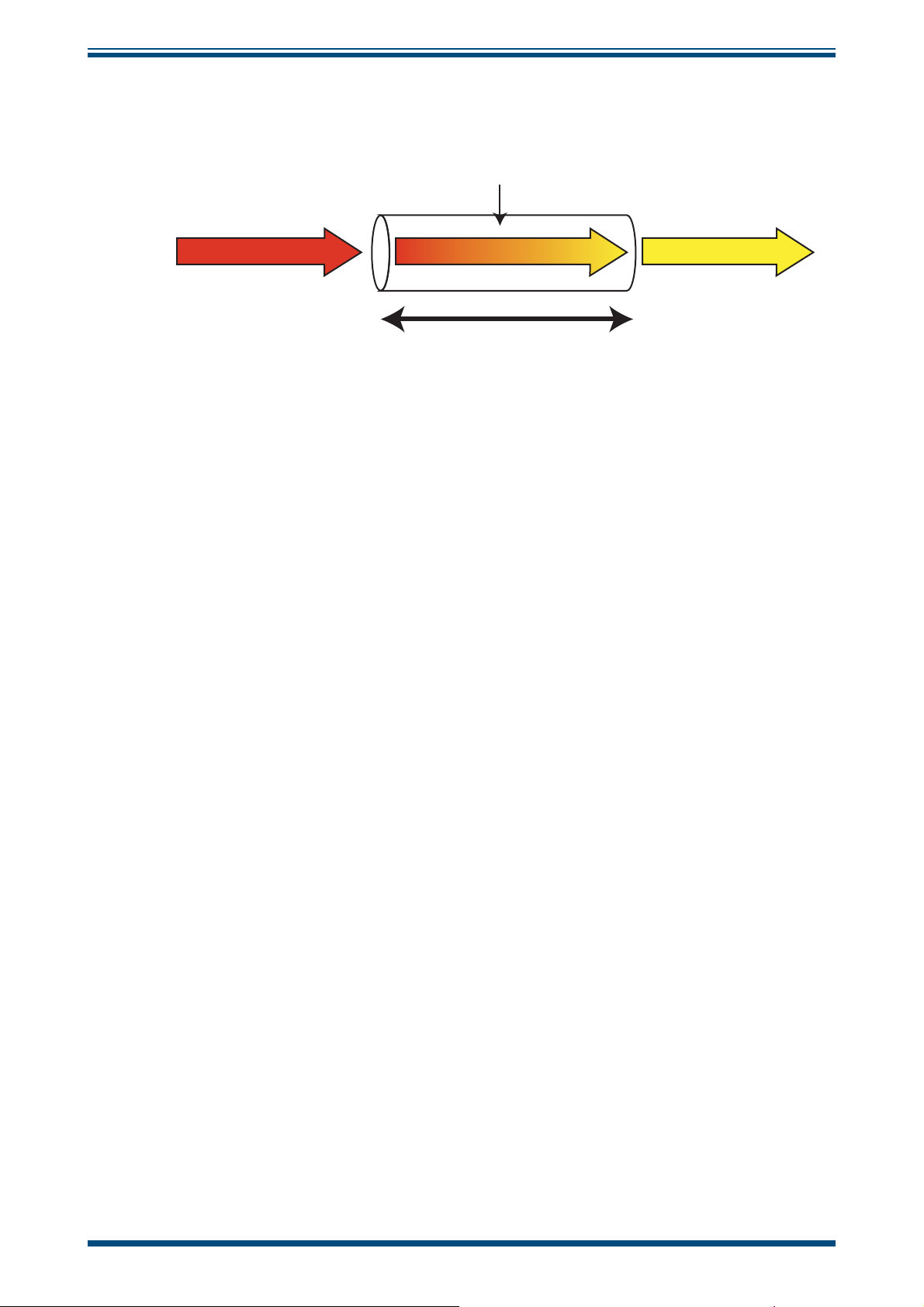
referred to as the Beer-Lambert Law.
A
c =
ε
l
where:
A
= absorbance
ε
= extinction coeffi cient (absorption strength of gas at a specifi c wavelength)
l
= sample cell path length
c
= gas concentration
(l)
This law states that, if the sample cell path length
coeffi cient of the water molecule (
gas absorbs light at a specifi c wavelength) is known, then, if the absorbance of laser
energy by the water molecules is measured (A), the water concentration (c) of the
sample stream can be calculated. This gas law is the basis of all photometric gas
absorption measurement.
ε
- a constant that describes how strongly a particular
is known, and the extinction
2 97319 Issue 4.2, November 2018
Page 11
OptiPEAK TDL600 User’s Manual
Beer Lambert law
concentration (c)
INTRODUCTION
Absorbent
I
O
I
X
Path length (l)
Figure 1
The Michell OptiPEAK TDL600 uses a tunable diode laser source to generate a narrow
and coherent beam of near infrared (NIR) energy at the precise resonant wavelength
of water vapor. Traditionally, infrared analyzers use broadband sources which generate
a wide gamut of wavelengths. To make these analyzers as selective as possible to
moisture only, optical fi lters have to be deployed to 'narrow' the range of wavelengths
that are fi nally passed through the sample. These fi lters do not offer very high selectivity
- they are quite broadband, which can lead to signifi cant spectral interference, as other
gas peaks close to the water absorption peaks are also detected, leading to cross
interference, drift and general degradation in measurement performance.
In contrast, the laser has a bandwidth of less than 0.0001 nanometers. This means the
laser is very selective in detecting only the water and not any other gases present in
the gas stream.
Beer Lambert Law
This optical technique also has the advantage that the analyzer uses a non-contact
method of measurement, i.e. there is no sensing element in contact with the gas
stream. This offers a highly robust and reliable measurement, as only photons of light
pass through the gas. This provides very fast response and no long wet-up or dry-down
times.
Michell Instruments 3
Page 12
INTRODUCTION
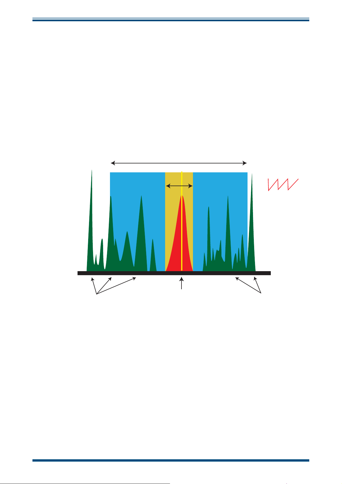
1.3.1 Measurement Using a Laser
The diagram below illustrates the advantages of using a laser source, compared to a
traditional broadband source.
The water absorption peak is shown in the center of the diagram (red area). The width
of the laser beam is very narrow and is represented by the yellow line.
The laser wavelength is varied in order to scan across the water absorption peak (yellow
area). By scanning the peak in this way, important information can be extracted, such
as changes to the absorption peak caused by variation in the sample gas. This very
precise scan range minimizes any overlap with nearby absorption bands, as would be
the case with conventional broadband infrared sources and optical fi lters (blue area).
Typical broadband source bandwidth
OptiPEAK TDL600 User’s Manual
Scan range
5 Hz ‘sawtooth’
laser scan
Conventional IR
source gives
very broad
transmission
Potential interferant gases Potential interferant gases
Gas absorption
(peak of interest)
Bandwith
approximately 0.05nm
Figure 2
Laser Scan
4 97319 Issue 4.2, November 2018
Page 13
OptiPEAK TDL600 User’s Manual
INTRODUCTION
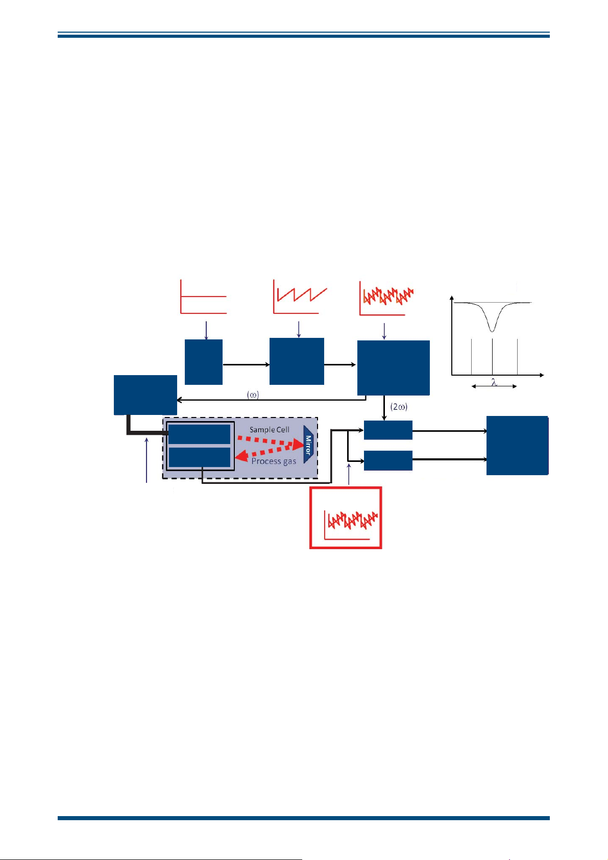
The schematic of the laser measurement system is shown in
Figure 3
below. This
highlights the major control and signal processing sections of the analyzer. The analyzer
uses the WMS (Wavelength Modulation Spectroscopy) technique, in combination with
proprietary signal processing algorithms to provide a selective response and high
sensitivity to moisture.
Here, a single frequency, distributed feedback (DFB) laser diode is tuned by applying
a current ramp to the laser. A further sinusoidal modulation is then applied. Lock-in
detection is applied to the photo-detector signal obtained by passing the tuned laser
radiation through the gas cell. The second harmonic signal from the lock-in detection is
measured to recover the spectroscopic peak of interest. WMS offers a practical method
of recovering weak signal changes from a dilute trace gas sample. WMS is becoming
wide spread within the sector of natural gas monitoring and represents current stateof-the-art technology.
Temperature
controlled
diode laser
Diode
current
Diode
laser
power
Launch head
Detector
Ramp
current
High
frequency
‘carrier’
modulation
Second harmonic
Mixer
Filter
Direct signal
Laser scanning
Signal
processing
Fiber Optic cable
Figure 3
Det. current
System Block Schematic
Michell Instruments 5
Page 14
INSTALLATION
!
2 INSTALLATION
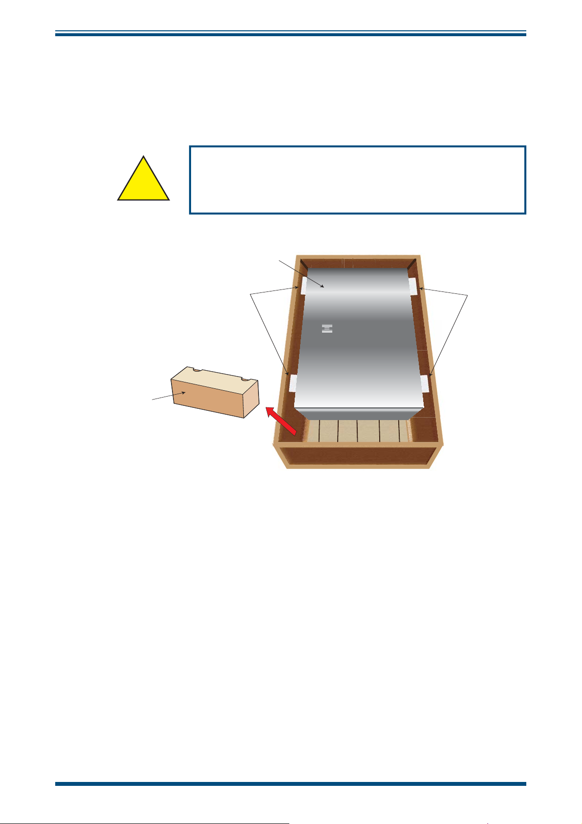
2.1 Unpacking the Instrument
Open the crate and unpack carefully as follows:
The instrument is heavy and should not be lifted alone.
Mechanical lifting aids may be required for larger systems.
OptiPEAK TDL600 User’s Manual
WARNING:
3
2
1
Figure 4
1. Remove the accessories box (1).
2. Remove the spacer foam (2).
2
Unpacking the TDL600
3. Remove the instrument enclosure (3) and set it down at the site of
installation.
It is recommended to save all the packing materials for the purpose of returning the
instrument for warranty claims.
The accessories box should contain the following items:
• Calibration Certifi cate
• Application Software CD
• User Manual
• CD containing System Documentation
6 97319 Issue 4.2, November 2018
Page 15
OptiPEAK TDL600 User’s Manual
!
!
2.2 Lifting and Handling
This product is in excess of 75kg (165lbs).
Personnel must observe suitable lifting and handling
The TDL600 is not designed as portable or transportable equipment. The product should
be rigidly fi xed in position as per the full installation instructions.
Appropriate lifting and handling techniques should be used during the installation process.
Before commencing any lifting or handling ensure that its intended location is suitable
and appropriately prepared. Make sure that mounting point design considerations have
employed locally approved safety factors.
INSTALLATION
WARNING:
precautions.
When handling and installing this instrument (particularly after removal from its
packaging) ensure that it is not dropped, impacted or subjected to high levels of
vibration or environmental conditions that may impair its operation.
2.3 Laser Safety
This product contains a Diode Laser with an invisible beam, operating in the near
infrared range. The laser as used in this product classifi es it as a CLASS 1 product.
For the purposes of CDRH and FDA Registration the OptiPEAK TDL600 complies with
21CFR1040 with deviations pursuant to Laser Notice 50 and with IEC/EN 60825-1:2007.
WARNING:
This product is a CLASS 1 LASER PRODUCT.
Beware of Laser radiation.
Do not access the Laser.
Do not view the Laser directly.
WARNING:
Use of controls or adjustments, or performance of
procedures other than those specifi ed herein, may result in
hazardous radiation exposure.
Michell Instruments 7
Page 16
INSTALLATION
!
2.4 Hazardous Area Safety
Refer to Appendix G for the Hazardous Area Certifi cation of this product.
This product is fi tted with a marking label that contains Hazardous Area information
pertinent to the suitable location and installation.
During all installation and operation activities, local regulations and permitted working
routines must be observed. Installation should only be performed by competent
personnel and in accordance with IEC 60079-14:2007 and EN 60079-14:2008 or local
equivalent.
Cable glands / conduit seals shall be installed in accordance with the manufacturer’s
instructions.
Conduit seals used should be suitable for a reference pressure of 6.1 bar (89 psi).
Repair and servicing of this equipment must only be carried out by the manufacturer.
OptiPEAK TDL600 User’s Manual
WARNING:
This product is certifi ed safe for use in a Zone 1 and Zone 2
area only. This product must not be installed or used within
a Zone 0 area.
WARNING:
This product must not be operated within an explosive
atmosphere greater than 1.1 bara (16 psia).
WARNING:
This product must not be operated within an enriched
oxygen atmosphere (more than 21% oxygen content).
WARNING:
This product must not be operated outside of the
temperature range of -20 to +55°C (-4 to +131°F)
WARNING:
The analyzer enclosure of this product provides Exd
protection, partly through the threads used for mounting
the lid, stopping plugs and cable gland. At all times effort
should be made to ensure these threads are suitably
protected from damage and that only appropriately rated
mating parts are applied to them, in accordance with the
certifying requirements.
8 97319 Issue 4.2, November 2018
Page 17

OptiPEAK TDL600 User’s Manual
DANGER
Electric
Shock Risk
2.5 Electrical Safety
During the installation of this product, ensure that all
applicable national and local electrical safety regulations are
Always ensure that power is switched off prior to accessing
the product for any purpose other than normal operation, or
prior to disconnecting any cables.
INSTALLATION
WARNING:
observed.
WARNING:
2.5.1 Equipment Ratings and Installation Details
The following mandatory statements refer to the Ex certified TDL600 Analyzer and
sampling system.
This equipment must be supplied with a voltage in the range of 90 to 264 V AC, 50/60
Hz. Maximum power rating depends on chosen standard options, 80W to 250W.
All electrical connections to the analyzer are made through junction boxes, mounted on
the panel of the sample system in accordance with Section 2.8.
Any power cable should be 3 core over sleeved, with minimum 0.5mm insulation
and rated at 300 V. Cables should have Live (L), Neutral (N) and Earth [Ground] (E)
conductors. Ensure suitably rated power supply cables and glands are used to ensure
that electrical safety is maintained. Ensure the power supply can deliver suffi cient power
to meet the consumption requirements.
Any power supply terminals and voltages must be suitably separated from the other I/O
requirements to this product.
Before applying power, perform a continuity test to ensure that the power supply cable
and the TDL600 are effectively connected to the protective Earth.
Michell Instruments 9
Page 18
INSTALLATION
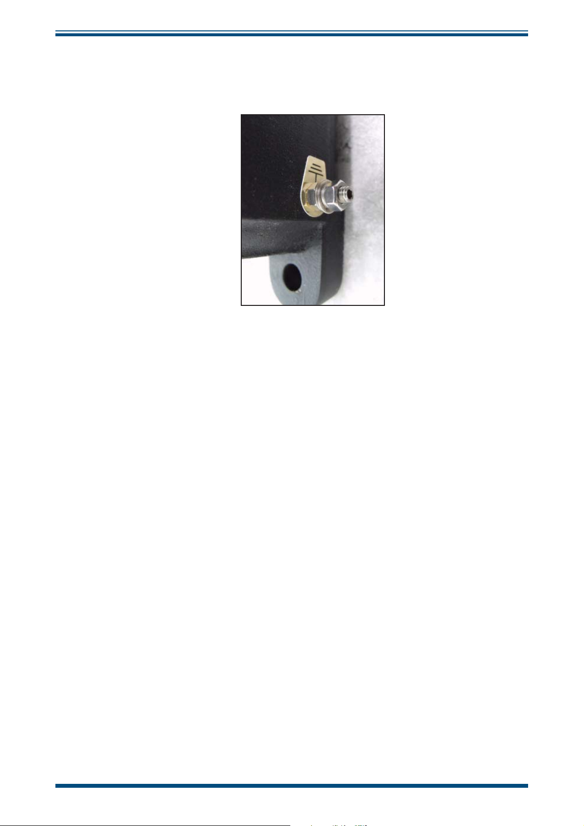
The protective Earth terminal is mounted internally and the Earth wire connected to it
should never be disconnected. The analyzer enclosure is supplied with an external earth
stud at the lower right hand side. This earth stud is connected to the sampling system
earth using 4mm2 minimum earthing bonding.
OptiPEAK TDL600 User’s Manual
Figure 5
Fuse: A replacement fuse can be obtained by contacting Michell Instruments' technical
support. Fuse rating = 5 x 20mm 2.5 A anti-surge to IEC 60127-2.
This measuring product is designed, where applicable and possible, to be in compliance
with EN/BS/IEC61010 safety requirements or electrical equipment or measurement,
control, and laboratory use. This product is designed to be safe at least under the
following conditions: between a temperature range of -40 to +60°C (-40 to +148°F),
in maximum 80% relative humidity for temperatures up to +31°C (+88°F) decreasing
linearly to 50% RH at +50°C (+122°F). Supply voltages of ±10% and transient over
voltages up to Overvoltage Category II. Pollution Degree 2. Altitudes up to 2000m.
Outdoor mounting is permitted using suitably rated glands equivalent to NEMA 4 / IP66.
See Appendix A, Technical Specifi cation, for full operating parameters.
NOTE: Do not remove or exchange any of the cables or electrical components
supplied with this product. Doing so will invalidate all warranties.
There are no additional or special electrical safety requirements other than those
referred to in this manual.
For location and mounting arrangements please refer to the relevant sections of this
manual.
Earthing Stud And Nut Washer Assembly
Installation of this equipment must include the provision of a suitable and locally
positioned power isolation switch or circuit breaker. Indication of the purpose of the
switch or circuit breaker is strongly recommended. An over-current protection device
should be rated to a maximum of 3 A.
This equipment and all power isolation devices must be installed in a location and
position that allows safe and easy access to their operation and is able to rigidly support
the equipment.
10 97319 Issue 4.2, November 2018
Page 19

OptiPEAK TDL600 User’s Manual
!
Do not install this equipment in a location that would expose it to impact or high levels
of vibration.
Operation of this equipment, other than in a manner specifi ed by the manufacturer, may
impair the safety protections provided.
The safe installation of this equipment and any system incorporating this equipment is
the responsibility of the installer. Ensure local regulations and requirements are referred
to prior to any installation commencing.
2.6 Pressure Safety
This product is used in conjunction with pressurized gases.
Pressurized gas should only be handled by suitably trained
Observe pressurized gas handling precautions.
INSTALLATION
WARNING:
personnel.
The TDL600 measurement chamber requires pressurized gas to be connected to it.
Observe pressurized gas handling regulations. Only suitably trained personnel should
carry out tasks that include the use of pressurized gas media.
The TDL600 measurement cell accepts a maximum sample pressure of 1.4 bara (20.3 psia).
2.7 Basic Installation Guidelines
The OptiPEAK TDL600 Moisture Analyzer Sampling System gas handling components
are assembled onto a stainless steel mounting plate suitable for wall mounting.
The outdoor version Sampling System provides environmental ingress protection to IP66
and should be mounted vertically, free of any appreciable vibration, in a permanently
shaded position to prevent heating effects through sun radiation. The Sampling System
enclosure can be specifi ed with optional thermostatically controlled heating (fi xed set
point). Optional enclosure cooling, using a compressed-air-driven vortex tube and
fi xed set point thermostat, is recommended for installation in hot climates (>+45°C
(>+113°F)).
NOTE: Any TDL being installed within a plant where it cannot vent to open
atmosphere needs a fl are line connection that runs to the highest point and
enters the fl are system from a topside connection. This is to prevent liquids
present in the fl are stack from draining back into the analyzer system.
NOTE: The actual detailed confi guration will be shown in the as-built drawings
provided with the shipped analyzer.
For start-up instructions refer to Section 3.
Michell Instruments 11
Page 20
INSTALLATION
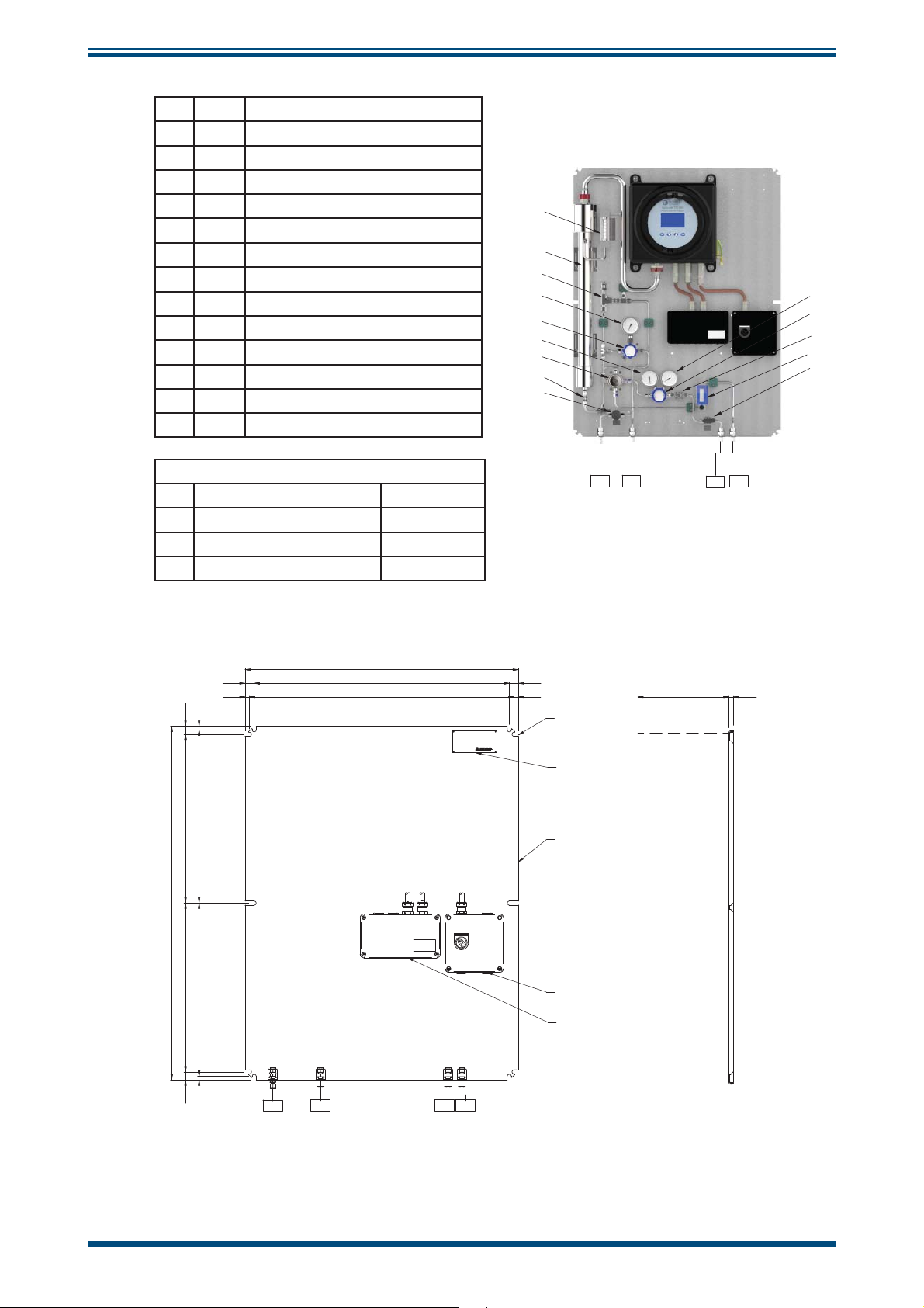
1 BV1 Ball Valve
2 F2 Particulate Filter
3 PR1 Pressure Regulator
4 PG1 Pressure Gauge
5 PR2 Pressure Gauge
6 F2 Coalescing & Membrane Filter
7 PR2 Pressure Regulator
8 PG3 Pressure Gauge
9 PRV1 Pressure Relief Valve
10 FM1 Flowmeter
11 AN1 Moisture Analyzer
12 MV1 Metering Valve
13 NV1 Needle Valve
14 FM2 Flowmeter
TP1 Sample Gas Inlet 1/4” NPT (F)
TP2 Sample Gas Outlet 1/4” NPT (F)
TP3 Bypass Flow Gas Outlet 1/4” NPT (F)
TP4 Letdown Gas Vent/Drain 1/4” NPT (F)
TP Connections
OptiPEAK TDL600 User’s Manual
10
11
9
8
7
5
6
12
13
TP2TP4
TP1
TP3
4
3
2
14
1
Figure 6
25.0 700.0 CRS 25.0
12.0 726.0 CRS 12.0
970.0
463.0 CRS 463.0 CRS
475.0 CRS 475.0 CRS
OptiPEAK Sampling System - Typical Indoor Version
750.0
250.0
MIN. CLEARANCE
MOUNTING HOLES
(10x
MODEL: OPTIPEAK TD L600
TYPE: PROCESS MOISTURE ANALYZER
SERIAL NUMBER : nnnn nn /2017
WO NUMBER : BC4556 5
www.michell.com
11mm)
316SS NAMEPLATE
316SS MOUNTING
PLATE
POWER INLET
CABLE ENTRY
(M20)
SIGNAL OUTPUTS
CABLE ENTRIES
(2 x M20)
12.0
22.0 22.0
10.0 10.0
TP04
TP02
TP01 TP03
Figure 7
12 97319 Issue 4.2, November 2018
OptiPEAK Sampling System - Typical Indoor Version
Page 21
OptiPEAK TDL600 User’s Manual
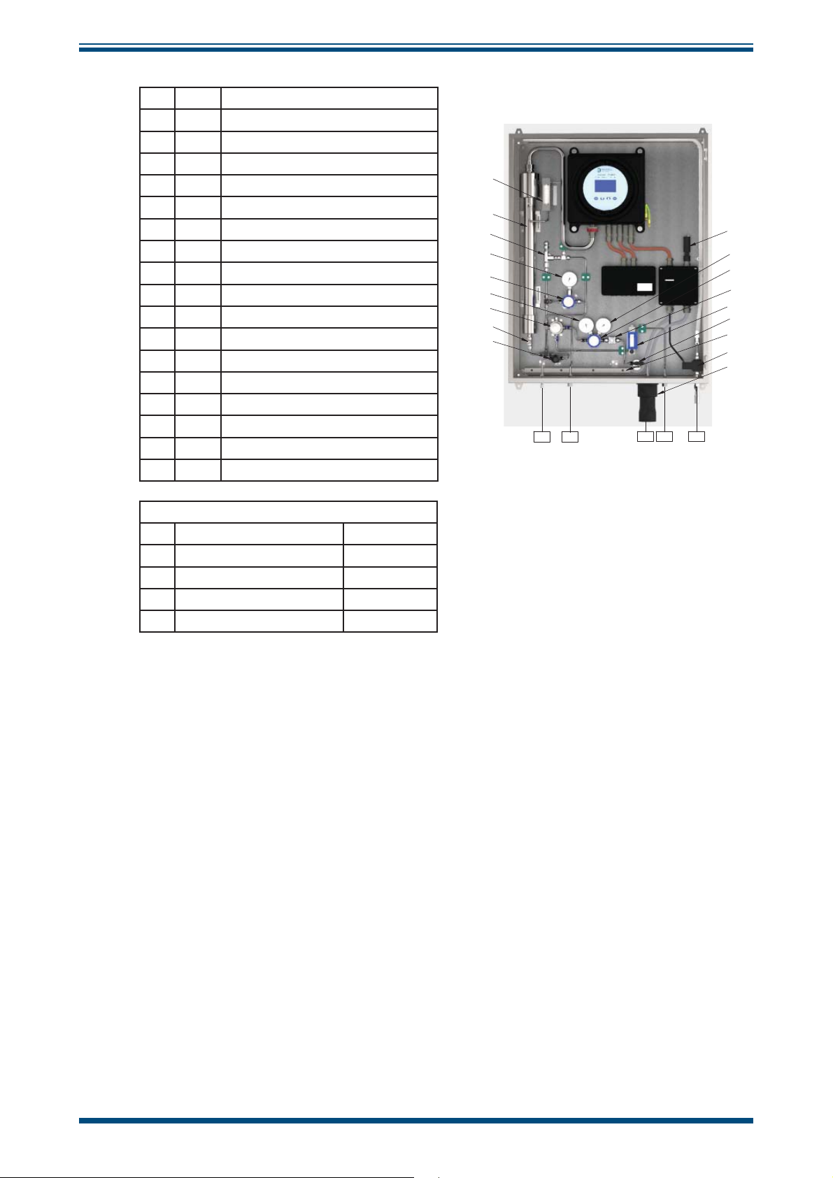
1 BV1 Ball Valve
2 F2 Particulate Filter
3 PR1 Pressure Regulator
4 PG1 Pressure Gauge
5 PG2 Pressure Gauge
6 F2 Coalescing & Membrane Filter
7 PR2 Pressure Regulator
8 AN1 Pressure Gauge
9 FM1 Pressure Relief Valve
10 PRV1 Flowmeter
TS1
11
12 MV1 Metering Valve
13 FM2 Needle Valve
14 NV1 Flowmeter
15
16
SOV1
17
18
Moisture Analyzer
HT
Enclosure Heater
TS1
Thermostat
Solenoid Valve
TH
Trace Heating
INSTALLATION
10
11
9
8
7
5
6
12
13
TP4 TP3
TP2
TP1
16
4
3
2
14
1
15
17
18
TP5
TP Connections
TP1 Sample Gas Inlet 1/4” NPT (F)
TP2 Sample Gas Outlet 1/4” NPT (F)
TP3 Bypass Flow Gas Outlet 1/4” NPT (F)
TP4 Letdown Gas Vent/Drain 1/4” NPT (F)
TP5 Vortex Cooler Inlet 1/4" NPT (F)
Figure 8
OptiPEAK Sampling System - Typical Outdoor Version
Michell Instruments 13
Page 22
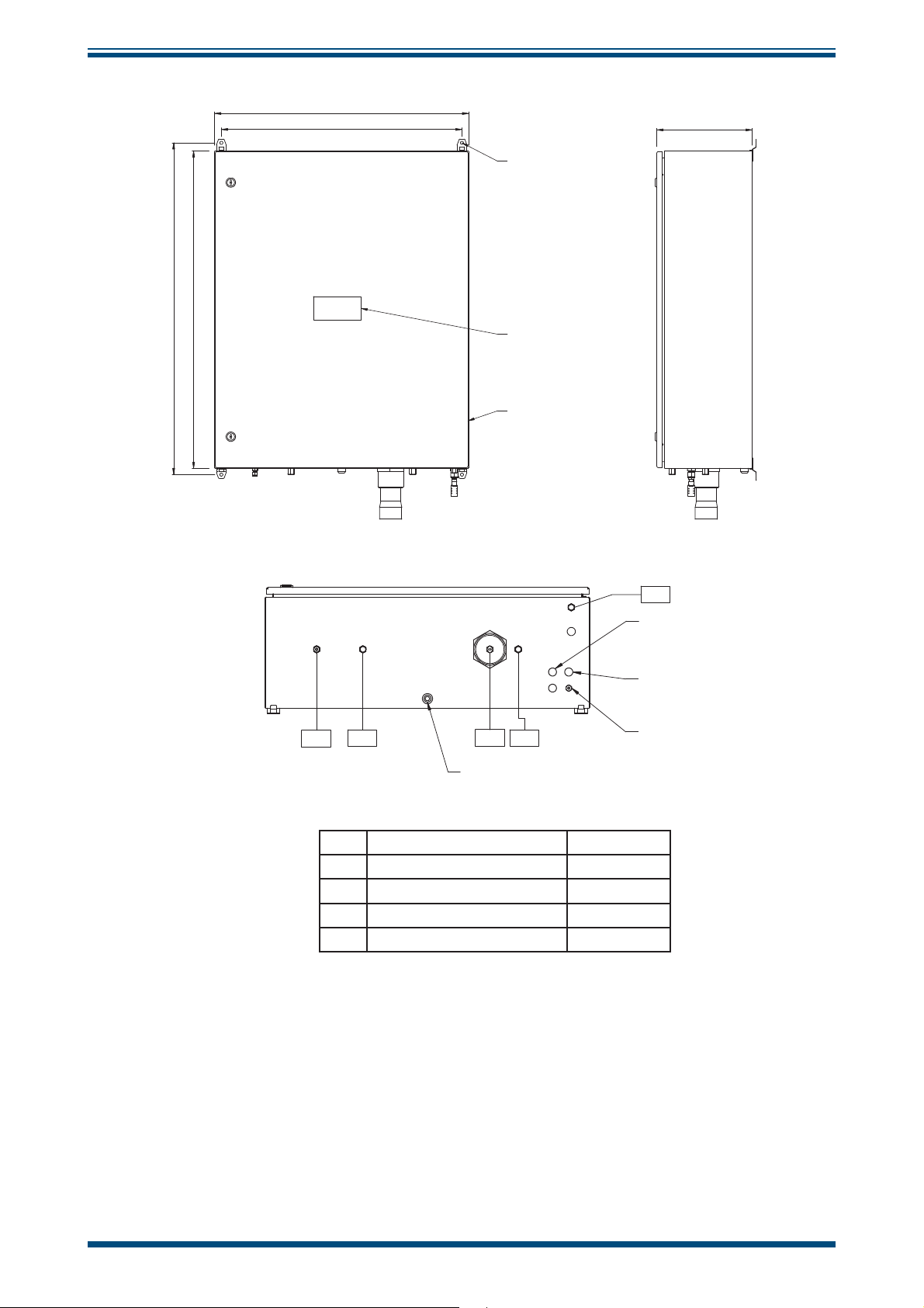
INSTALLATION
1045
1000
800
758
OptiPEAK TDL600 User’s Manual
300.0
MOUNTING HOLES
10mm)
(4x
316SS NAMEPLATE
ENCLOSURE (NOTE 1)
TP05
SIGNAL OUTPUTS
CABLE ENTRIES
(2 x M20)
POWER INLET
CABLE ENTRY
(M20)
TP04
TP02
TP01
TP03
BREATHER/DRAIN
EARTH STUD
TP1 Sample Gas Inlet 1/4” NPT (F)
TP2 Sample Gas Outlet 1/4” NPT (F)
TP3 Bypass Flow Gas Outlet 1/4” NPT (F)
TP4 Letdown Gas Vent/Drain 1/4” NPT (F)
TP5 Vortex Cooler Inlet 1/4" NPT (F)
Figure 9
OptiPEAK Sampling System - Typical Outdoor Version
14 97319 Issue 4.2, November 2018
Page 23

OptiPEAK TDL600 User’s Manual
!
2.8 Electrical Connections
All electrical connections to the TDL600 are made through junction boxes JB1 & JB2
(ATEX, IECEx and NEC500 Class I, Division 2 versions only).
INSTALLATION
WARNING:
Once the mains power connections are made to JB1 the
heaters and vortex cooling solenoid (if fi tted) will be
energized.
This includes:
• Power Connection
• Analog Outputs
• Analog Inputs (line pressure transmitter)
• Alarm Relays
• Modbus RTU / RS485 Connection
For the wiring diagram, consult the appropriate Appendix, depending on whether the
TDL600 was supplied with the indoor sample system, or the outdoor sample system:
Indoor Sample System Appendix B
Outdoor Sample System Appendix C
2.8.1 Power Connection
A single-phase AC mains power supply is required to operate the Analyzer and Sampling
System. The analyzer power supply can accommodate voltages from 90 to 264 V AC, 50/60
Hz. If enclosure heating or cooling options are selected, these will have defi ned voltage and
wattage requirements.
The factory-set power supply voltage is indicated on a yellow label located on the rear panel.
NOTE: The user cannot change the specifi ed power supply voltage.
Cable connections are made onto terminals within the Power Circuits junction box. Cable
entry into the junction box is provide via M20 threaded holes (fi tted with certifi ed stopping
plugs). Suitably certifi ed cable glands should be used (not supplied).
The power connection is made through JB1 (ATEX, IECEx and NEC500 Class I, Division
2 versions only) – refer to the appropriate Appendix.
Michell Instruments 15
Page 24

INSTALLATION
Terminals are marked:
NOTE: An earth stud is provided in the base of the enclosure. This must be
used to earth bond the Sampling System.
A power isolator switch is provided on the Power Circuits junction box for local power
isolation of the OptiPEAK TDL600 Moisture Analyzer (Main Unit only) for maintenance or
servicing. NOTE: This switch isolates the analyzer but does not isolate power
from ancillaries such as the heating/cooling circuits where fi tted.
2.8.2 Analog Outputs
OptiPEAK TDL600 User’s Manual
Terminal No. Power Supply
1 Live
5 Neutral
Earth
Three 2-wire analog outputs are provided that can be confi gured to represent any of
the directly measured or calculated output parameters. These outputs are active, selfpowered from the analyzer and can be set as either 0-20mA or 4-20mA.
For an overview of the analog output menu, refer to Section 3.7.6.1.
The analog output connections are made through JB2 (ATEX, IECEx and NEC500
Class I, Division 2 versions only) – refer to the appropriate Appendix.
2.8.3 Analog Inputs
Connection for process line pressure transmitter (optional).
Enables dynamic pressure compensation for calculation of moisture content
units.
Input 1
Input 2 No function
12 V DC excitation power provision for loop powered 4-20mA, 2-wire
transmitter. Transmitter must be able to function from 12 V DC excitation,
such as typical devices requiring 8 - 30 V DC.
Internal sensing resistor 100 Ω.
2.8.4 Alarm Relays
Three alarm relays are provided that can be triggered by any of the directly measured
or calculated output parameters. Each alarm relay has Common (CO), Normally Open
(NO) and Normally Closed (NC) contacts.
For detailed information on the alarms refer to Section 3.7.6.2.
The alarm relay connections are made through JB2 (ATEX, IECEx and NEC500 Class
I, Division 2 versions only) – refer to the appropriate Appendix.
16 97319 Issue 4.2, November 2018
Page 25

OptiPEAK TDL600 User’s Manual
2.8.5 Modbus RTU / RS485 Connection
The TDL600 features an RS485 port for digital communication, and uses a subset of the
Modbus RTU protocol. The RS485 connection should be confi gured with the following
parameters:
Parameter Value
Baud Rate 9600bps
Data Bits 8
Parity None
Stop Bits 2
A full list of Modbus registers can be found in Appendix E.
The RS485 connection is made through JB2 (ATEX, IECEx and NEC500 Class I,
Division 2 versions only) – refer to the appropriate Appendix.
INSTALLATION
2.9 Environmental Requirements
The environmental requirements of the analyzer (complete with sampling system) are
as follows:
Temperature
Indoor version +10 to +45°C (+50 to +113°F)
Outdoor version -20 to +45°C (-4 to +113°F)
Outdoor version with enclosure cooling option -20 to +55°C (-4 to +131°F)
Temperature (Storage) -30 to +60°C (-22 to +140°F)
Relative Humidity Less than 90% RH
If installed outside, the analyzer must be in a shaded position to prevent heating effects
through sun radiation.
Michell Instruments 17
Page 26
INSTALLATION
2.10 Sample Conditioning Requirements
Sample extraction, handling and conditioning techniques are of critical importance to assure
optimal performance and reliability of all gas analyzers that accurately quantify specifi c
components within a process gas composition. Michell Instruments' recommendations
and requirements in relation to the OptiPEAK TDL600 are outlined below.
Michell Instruments offers a range of sample extraction probes and sample conditioning
systems that have been selected and designed to exceed these minimum requirements.
For further information and advice please contact your local Michell offi ce or distributor
– refer to contact details on www.michell.com.
2.10.1 Gas Connections
Ensure that the process sample gas supply line is well fl ushed
through to clear any liquids and debris present, prior to
connection to the Sampling System.
OptiPEAK TDL600 User’s Manual
Connections are as follows - refer to Flow Diagram in Appendix D:
• TP1 Sample Gas Inlet
• TP2 Sample Gas Outlet
• TP3 Bypass Outlet
• TP4 System Vent/Drain
TP1 to TP3 are 1/4” NPT(F), TP4 is 1/4" OD.
2.10.2 Sample Flow Gas Handling Components
The sample fl ow gas handling components are as follows:
• Gas Inlet Isolation Valve (BV1):
Allows user to manually isolate the system from the process sample gas
supply line for maintenance or servicing.
• Particulate Filter (F1):
Provides protection to regulator from particulates
• Line Pressure Gauge (PG1):
Indicates the sample gas line pressure.
• Pressure Regulator 0-35 Bar (PR1):
Allows the user to manually set the sample gas analysis pressure for moisture
measurement. 1st stage pressure regulation.
• Regulated Pressure Gauge (PG2)
Indicates pressure set on PR1.
18 97319 Issue 4.2, November 2018
Page 27

OptiPEAK TDL600 User’s Manual
• Particulate/Coalescing Filter (F2):
Provides system protection from contamination of entrained liquids and
particulates using membrane fi ltration.
• Pressure Regulator 0-4 Bar (PR2):
2nd stage pressure regulation for moisture measurement.
• Input Pressure Gauge (PG3):
Indicates cell input pressure as set at PR2.
• Insert Pressure Relief Valve (PRV1)
Protects AN1 from over pressure
• Metering Valve (MV1):
Allows the user to manually set the sample gas fl owrate into the TDL gas
cell.
INSTALLATION
• Moisture Analyzer (AN1):
TDL600 Process Moisture Analyzer
• Flowmeter (FM1):
Provides indication of the sample gas fl ow rate through the TDL gas cell.
• System Drain Needle Valve (NV1):
Allows the user to manually letdown the sample gas pressure trapped in the
system for maintenance or servicing.
The bypass fl ow gas handling components are as follows:
• Bypass Flowmeter & Valve (FM2):
Allows the user to manually set and provide indication of the bypass gas fl ow
rate across the membrane fi lter.
Sample Extraction and Impulse Tubing
An insertion probe, with tip positioned within the central one-third of the crosssectional area of the pipe, should be used to extract a sample with a composition that
is representative of the majority of gas fl owing within the pipeline. Attention should
be given to the installation of impulse tubing connecting from the sample probe to the
analyzer sample conditioning system. Analytical grade acid-etched stainless steel tubing
should be used, which has a low moisture sorption capacity. Tube size should be 1/8"
or 3mm diameter, or 1/4” or 6mm as a maximum, to ensure that sample transportation
delay time is kept to a minimum. Likewise, to ensure the best dynamic response of
the complete installed analyzer system, the positioning of the analyzer with sample
conditioning system should be as close to the sample extraction probe as possible.
Michell Instruments 19
Page 28

INSTALLATION
To avoid any risk of condensation forming during transportation to the analyzer, and so
ensure that the integrity of the sample gas is maintained, the temperature of the sample
impulse tubing must be maintained at a temperature above the highest envisaged water
dew point. It is recommended that the sample tubing temperature is maintained at least
5°C (10°F) above the maximum water dew point at the prevailing pressure, as a suitable
‘safety’ margin. Self-limiting heating cable should be applied to the complete length of
the impulse tube, enclosed within suitable insulation. Trace heated tube bundle is a
factory fi tted option for Michell-produced sample conditioning systems.
Sample Conditioning System
The Michell designed sample conditioning system addresses the needs for filtration,
pressure reduction and sample flow control. To maintain cleanliness of the analyzer's
optical detection system, the process sample flow is filtered to eliminate entrained
liquids and particles. To provide protection against hydrocarbon condensates and
compressor oils that may be present in process natural gas, we use a micro-porous
membrane filtration with an oleophobic element specifically intended to reject such
low-surface tension liquids. Pressure reduction and sample flow control can achieve
0.5 Nl/min (1 scfh) sample flow at atmospheric pressure. Flow control is achieved by
a fine metering valve operating with a low upstream pressure and located at the inlet
to the analyzer optical cell. Flow indication on the outlet of the analyzer optical cell
is achieved with a variable area flow meter without a flow valve so as to avoid any
significant back-pressure.
OptiPEAK TDL600 User’s Manual
The sample gas exhaust should vent freely to atmosphere to avoid any signifi cant back
pressure to the analyzer optical cell. A suitable fl ame arrestor can be installed at the
fi nal vent point, which should be selected in accordance with site safety requirements
governing such atmospheric release of gas. The bypass fl ow from the membrane fi lter
could be taken to the site fl are system, as back-pressure is less critical in that case
(maximum 3 barg).
The enclosure for outdoor installed systems must be located within 100% shade from
direct sun, by the addition of an effective sun canopy, if necessary.
Combined Sample Extraction Probe with Integral Membrane Filter and
Pressure Reduction
It is possible to simplify the sample extraction and sample conditioning requirements
by use of an insertion sample probe that incorporates membrane fi ltration with sample
pressure reduction. The design of such combination probes has both the membrane
fi lter element and the pressure regulation control device at the tip of the probe, so
within the process pipeline fl ow. Final fi ltration and sample pressure reduction should
still be provided within the analyzer sampling system.
20 97319 Issue 4.2, November 2018
Page 29

OptiPEAK TDL600 User’s Manual
INSTALLATION
2.11 Options
2.11.1 Enclosure Heater Temperature Control (Outdoor systems ONLY)
Sampling systems fi tted within enclosures are temperature controlled to maintain a
constant temperature environment of at least 10°C (18°F) above the highest envisaged
dew-point temperature, independent of surrounding temperature variations. The
temperature control system consists of a heater controlled by a fi xed preset thermostat
to provide internal ambient air temperature control of +20°C (>+68°F).
2.11.2 Vortex Cooling (Outdoor systems ONLY)
A sampling system enclosure cooling kit can be fi tted to the stainless steel enclosure.
The cooling device is a Vortex tube driven by instrument grade (liquid and particulate
free) compressed air. A fi xed thermostat maintains an internal ambient <+40°C
(104°F) controlling a solenoid valve permitting the fl ow of compressed air through the
Vortex tube. A manifold (clear plastic pipe) positioned around the internal
walls of the enclosure distributes the cooling air throughout.
2.11.3 Trace Heated Sample Line
As an option, a trace heated sample line can be supplied with the Sampling System. This
ensures that the sample gas temperature from the process take-off point to the analyzer
is maintained at a constant temperature, independent of surrounding temperature
variations.
The trace heated tubing bundle consists of 6mm or ¼” OD 316L stainless steel seamless
tube and BSX™ self-regulating heating cable with non-hygroscopic glass fi ber insulation
and polymer outer jacket.
The self-regulating heat output of BSX™ cable varies in response to the surrounding
conditions along the entire length of a circuit. Whenever the heat loss increases (as
the ambient temperature drops), the heat output of the cable increases. Conversely
when the heat loss decreases (as the ambient temperature rises), the cable reacts by
reducing its heat output.
Operation of the trace heated sample line is fully automatic. Once a mains power supply
is provided then no further adjustment is required.
The trace heated sample line is connected directly onto the
(via the bulkhead entry seal gland, when fi tted to an enclosure) within the Sampling
System and the heating cable is terminated onto terminals within the Power Circuits
junction box. Cable entry into the junction box is via an EExe cable gland (supplied).
Gas Inlet Isolation Valve
See wiring diagram for termination details (Appendix C).
Michell Instruments 21
Page 30

OPERATION
!
!
3 OPERATION
Operation of the OptiPEAK TDL600 Sampling System should be carried out in conjunction
with, and referring to, this manual, prior to commencing the System Start-Up Procedure
(Section 3.1).
Before commencing the start-up procedure it is essential to ensure that the installation
conforms to the correct hazardous area and local plant standards.
Before any gas pressure is applied, check that all gas inlet & outlet connections are fully
tightened up and that all valves and regulators are in the closed position.
Additionally, for the outdoor version, the heater/thermostat circuit will need to achieve
the set-point temperature.
OptiPEAK TDL600 User’s Manual
BEFORE power is applied to the Sampling System check that the
OptiPEAK TDL600 Power Isolator switch (JB1) is set to the
position.
OFF
Check that all customer supplied cables are according to certifi cated approved
specifi cations and, as a minimum, are as described below:
Recommended Customer Cable Requirements
Power Cable 3 core, 0.75mm
Communications Cable
3.1 Start-Up Procedure
See Flow Diagram in Appendix D.
If the unit is left in storage for an extended period prior to
installation, it is recommended that the system be run on
2
conductor area (6A)
For use with 4-20 mA only or Modbus only
1 pair individually screened 0.5mm
overall screen (BS5308 or equivalent)
For use with 4-20 mA and Modbus
2 pair individually screened 0.5mm
overall screen (BS5308 or equivalent)
the sample gas for up to 24 hours before use to allow for
proper system dry down.
2
(min) conductors with an
2
(min) conductors with an
1. Switch on the analyzer power using the Power Isolator Switch (JB1).
WARNING:
Once the mains connections are made to JB1 the heaters
and vortex cooling solenoid (if fi tted) will be energized.
22 97319 Issue 4.2, November 2018
Page 31

OptiPEAK TDL600 User’s Manual
2. Ensure the System Drain Needle Valve (NV1) is CLOSED.
3. Ensure the Measurement Cell Pressure Regulators (PR1 & PR2) and
Bypass Flow Metering Valve (FM2) are fully CLOSED.
4. Ensure the Measurement Cell Metering Valve (MV1) is fully CLOSED.
5. Slowly OPEN the Gas Inlet Isolation Valve (BV1) to allow sample gas to
enter the Sampling System.
6. Perform leak tests using snoop (or equivalent leak test fl uid) on any new
system gas connections.
7. Set Pressure Regulator (PR1) to 20 barg, indicated on PG2 and then
adjust the Measurement Cell Pressure Regulator (PR2) to show 2 barg on
Pressure Gauge (PG3).
8. Adjust the Bypass Flow Metering Valve (FM2) to indicate a gas fl ow rate
of approximately 3 Nl/min (6.5 scfh).
9. Adjust the Measurement Cell Flow Metering Valve (MV1) to indicate
a sample gas fl ow rate of approximately 0.5 Nl/min (1 scfh) on the
Measurement Cell Flow Meter (FM1).
OPERATION
10. Close the enclosure door and allow the system temperature to stabilise.
3.2 Shut Down Procedure
1. Isolate the Sampling System from the sample gas supply line by CLOSING
the Gas Inlet Isolation Valve (BV1).
2. Allow approximately 2 minutes for the Sampling System to begin to
depressurize. Fully depressurize the Sampling System by CLOSING the
Bypass Flow Metering Valve (FM2) and OPENING the System Drain
Needle Valve (NV1).
3. Ensure the Power Isolator switch (JB1) is in the OFF position.
4. After approximately 2 minutes close the System Drain Needle Valve (NV1).
Michell Instruments 23
Page 32

OPERATION
3.3 User Interface
The OptiPEAK features a 4.3” color display.
3.3.1 Interface Controls
OptiPEAK TDL600 User’s Manual
OptiPEAK TDL600
Process Moisture Analyzer
ALARM!
ppm
V
21.4
Dewpoint ISO at Line Pressure Line Pressure
-17.5 °C 61.2 barg
No faults
1
2
3
Alarms
ppm
V
>20
Dewpt
>-10
RTD Temp
<5, >50
TRIPPED
OK
Four capacitive touch keys are used to navigate the menu system.
Key presses are detected through the glass front panel, and are indicated by a blue LED
above the key.
3.3.2 ‘Up/Down Arrow’ Keys
ESC ENTER
Figure 10
User Interface
Figure 11
Up/Down Arrow Keys
Up () and Down () keys are used to change pages, scroll through lists and
The
adjust values.
Some parameters, such as the output and alarm minimum and maximum values activate
the numerical entry screen. On this screen, the
the
Up () key changes the value of the currently selected digit.
Down () key selects the next digit and
24 97319 Issue 4.2, November 2018
Page 33

OptiPEAK TDL600 User’s Manual
3.3.3 ‘ENTER’ Key
OPERATION
ENTER
The ENTER key is used to select or de-select a highlighted item in a menu list.
Some parameters, such as the output and alarm minimum and maximum values activate
the numerical entry screen. On this screen, the
and returns to the previous screen.
3.3.4 ‘ESC’ Key
The ESC key is used to return to the previous menu, Run-Mode Screen, Main Menu or
Advanced Settings Screen.
Some parameters, such as the output and alarm minimum and maximum values activate
the numerical entry screen. On this screen, the
returns to the previous screen.
Figure 12
Figure 13
'ENTER’ Key
ENTER key accepts the displayed value
ESC
‘ESC’ Key
ESC key discards the new value and
3.4 Description of Measured Parameters
ppm
V
lb/MMscf
Pw
Dewpoint ISO
Dewpoint IGT
DP Ideal
mg/m3
Line Pressure*
Spare Input*
parts per million of H2O by volume
pounds H2O per million standard cubic feet (20°C, 101.325KPa)
partial vapor pressure of H2O in kilopascals
dew-point temperature (with respect to ice below 0°C), natural gas
(ISO18453)
dew-point temperature (with respect to ice below 0°C), natural gas
(IGT Bulletin 8)
dew-point temperature
milligrams H2O per cubic meter (15°C, 101.325 kPa)
Line pressure from current (mA) input
Spare current loop input for a user-connected device
* Available as secondary or tertiary parameter only
Michell Instruments 25
Page 34

OPERATION
3.5 Default Settings
On initial start up, the TDL600 Regional Setting is set to EU and metric units (i.e. Dew
Point to ISO 18453 and ºC) are selected. The Regional Setting can be changed to US
(see section 3.7.6.6), this is applies US standard units (i.e. lb/MMscf and ºF). The
default settings are shown here:
Top level menu - EU region Top level menu - US region
Parameters
Primary: ppm
Secondary: Dew-point ISO Secondary: lb/MMscf
Tertiary: mg/m
Display
Pressure units: barg Pressure units: psig
Temperature units: ºC Temperature units: ºF
Resolution (dp): 1 Resolution (dp): 1
Brightness (%): 100 Brightness (%): 100
Log menu
Logging disabled as default Logging disabled as default
V
3
OptiPEAK TDL600 User’s Manual
Primary: ppm
Tertiary: Dew-point ISO
V
3.5.1 Advanced Menu default settings
Outputs
Output 1 Output 2 Output 3
Parameter: ppm
V
Parameter: ppm
Type: 4-20 mA Type: 4-20 mA Type: 4-20 mA
Minimum: 0 Minimum: 0 Minimum: 0
Maximum: 1000 Maximum: 0 Maximum: 0
Alarms
All alarms disabled as default
Inputs
All inputs disabled as default
Modbus
Device Address: 1
Baud: 9k6
V
Parameter: ppm
V
26 97319 Issue 4.2, November 2018
Page 35

OptiPEAK TDL600 User’s Manual
3.6 Menu Structure
OPERATION
Run-Mode Screen
ESC
Main Menu
ENTER
Outputs
Outputs 1, 2, 3
Parameter
Type
Minimum
Maximum
Parameters
Primary
Secondary
Tertiary
Alarms
Alarms 1, 2, 3
Parameter
Type
Latching
Minimum
Maximum
Display Log Menu About Graph
Pressure
Unit
Temperature
Unit
Resolution
Log Period
Log #
Start Log
Contact &
Firmware Info
Measurement
Brightness
Clock Modbus
Date/
Time
Device
Address
Baud
Rate
Line
Pressure
Dewpoint
Source
Fixed
Pressure
Minimum
Maximum
Units
Inputs
Spare
Input
ppm
No
access
Minimum
Maximum
Enable
Selected
Primary
Parameter
Info
Region
Unit
Presets
Advanced
Settings
Password
7316
ENTER
N2-Mode
N2
Mode
Safe Mode
Not for
customer
use
Hysteresis
Enable
KEY
Press Up/Down keys
to change pages, scroll through
lists & adjust values.
Max/Min values activate the numerical
entry screen. Press Down key to select digit
& Up key to change value of selected digit.
ESC
Press ESC key to get back to Main Menu,
Advanced Menu or Run Mode Screen
depending on location.
Max/Min values activate the numerical
entry screen. Press ESC key to discard new
value & return to previous screen.
Figure 14
Menu Structure
ENTER
Press ENTER key to select or de-select a
highlighted item in a menu list.
Max/Min values activate the numerical
entry screen. Press ENTER key to accept the
displayed value & return to previous screen.
Michell Instruments 27
Page 36

OPERATION
3.7 Main Menu Screen
All instrument operating parameters, logging information, and advanced settings for
outputs, alarms and pressure are available through this screen.
This screen is accessed by pressing the ESC key from the Run-Mode Screen.
OptiPEAK TDL600 User’s Manual
Use the
ENTER key to access.
Press the
Up () and Down () keys to highlight the page of interest and press the
ESC key to return to the Run-Mode Screen.
Main Menu
Parameters
Display
Log Menu
About
Graph
Advanced Settings
Figure 15
Main Menu Screen
28 97319 Issue 4.2, November 2018
Page 37

OptiPEAK TDL600 User’s Manual
3.7.1 Parameters Screen
The Parameters Screen controls which measured or calculated parameters are shown
on the Run-Mode Screen.
OPERATION
This screen is accessed by pressing the
Use the
the
required and press the
Press the
Up () and Down () keys to highlight the parameter of interest and press
ENTER key to access. Use the Up () and Down () keys to choose the option
ENTER key to accept.
ESC key to return to the Main Menu Screen.
ENTER key from the Main Menu Screen.
Parameters
Primary: ppm
V
Secondary: Dew Point IGT
Tertiary: Line Pressure
Figure 16
Parameter Description
Parameter shown on large, top left pane of Run-Mode Screen
Primary
Available Options: ppm
ISO, Pw, mg/m3, lb/MMscf
Parameter shown on the leftmost smaller pane of Run-Mode
Screen
Secondary
Available Options: ppm
Ideal, Dewpoint IGT, Dewpoint ISO, Pw, mg/m3, lb/MMscf
Parameter shown on the rightmost smaller panel of Run-Mode
Screen
Tertiary
Available Options: ppm
Ideal, Dewpoint IGT, Dewpoint ISO, Pw, mg/m3, lb/MMscf
Table 1 Parameters Screen Parameters
Parameters Screen
, DP Ideal, Dewpoint IGT, Dewpoint
V
, Line Pressure, Spare Input, DP
V
, Line Pressure, Spare Input, DP
V
Michell Instruments 29
Page 38

OPERATION
3.7.2 Display Screen
The Display Setup Screen controls which units are used for temperature and pressure
on the display, alarm, and analog output screens. It also enables the brightness and
display resolution to be set.
OptiPEAK TDL600 User’s Manual
This screen is accessed by pressing the
Use the
the
required and press the
Press the
Up () and Down () keys to highlight the parameter of interest and press
ENTER key to access. Use the Up () and Down () keys to choose the option
ENTER key to accept.
ESC key to return to the Main Menu Screen.
ENTER key from the Main Menu Screen.
Display Setup
Pressure Units: kPa
Temperature Units: °C
Resolution (dp): 2
Brightness (%): 100
Figure 17
Parameter Description
Pressure unit used for cell pressure
Pressure Units
Available Options: psig, psia, MPa, kPa, barg, bara
Temperature
Units
Resolution (dp)
Brightness (%)
Table 2 Display Setup Screen Parameters
Temperature units used for dew point and temperature
Available Options: °C, °F
Number of decimal places used for display units
Available Options: 0, 1, 2
Brightness of display backlight
Available Options: 20 to 100%
Display Setup Screen
30 97319 Issue 4.2, November 2018
Page 39

OptiPEAK TDL600 User’s Manual
3.7.3 Log Menu Screen
The Data Logging Screen allows data-logging to the SD card, which is fi tted to the rear
of the display PCB. Refer to Section 4.2 for instructions on fi tting and removing the SD
card.
OPERATION
When logging is active it will be indicated by a disc icon
This screen is accessed by pressing the
Use the
the
required and press the
Press the
Up () and Down () keys to highlight the parameter of interest and press
ENTER key to access. Use the Up () and Down () keys to choose the option
ENTER key to accept.
ESC key to return to the Run Mode Screen.
ENTER key from the Main Menu Screen.
on the Run-Mode Screen.
Data Logging
Log Period: 15s
Log#: 0
Stop Log: No
Figure 18
Parameter Description
Sets the interval at which data is recorded in the log fi le
Log Period
Available Options: 15s, 1min, 5min, 30min, 1hr, 4hrs, 24hrs
Log #
Stop Log
Table 3 Data Logging Screen Parameters
0 - 9
Yes/No
Data Logging Screen
Michell Instruments 31
Page 40

OPERATION
3.7.4 About Screen
The Contact/About Screen shows the current fi rmware version and company contact
information.
OptiPEAK TDL600 User’s Manual
This screen is accessed by pressing the
Press the
ESC key to return to the Run Mode Screen.
Contact/About
Michell Instruments
Web: www.michell.com
Firmware Part no: 36219
Firmware ver: 01.09
Hw Serial No: 123123
Figure 19
ENTER key from the Main Menu Screen.
Contact/About Screen
3.7.5 Graph Screen
The Graph screen shows a graph of primary measurement parameter over time.
This screen is accessed by pressing the
Down () key changes the scale of the selected primary measurement parameter
The
axis. The
Press the
Up () key changes the scale of the time axis.
ESC key to return to the Run Mode Screen.
ENTER key from the Main Menu Screen.
300
250
200
150
100
50
V
ppm
0
0hrs-1-2-3-4-5-6-7
Figure 20
Graph Screen
32 97319 Issue 4.2, November 2018
Page 41

OptiPEAK TDL600 User’s Manual
3.7.6 Advanced Settings Screen
This screen is accessed by pressing the ENTER key from the Main Menu Screen.
Passcode
To safeguard against unauthorized adjustment of Advanced Settings options, an entry
lock is provided.
OPERATION
The user must fi rst input the access code
The Down () key selects the digit and the Up () key changes the value of the
currently selected digit. Press the
Screen.
After the passcode is entered use the
required and press the
Screen.
ENTER key or press the ESC key to return to the Run-Mode
ENTER key to access the Advanced Settings Options
7316.
Up () and Down () keys to choose the option
Advanced Settings
Outputs
Alarms
Inputs
Region
N2-Mode
Safe Mode
Clock
Modbus
Figure 21
Advanced Settings Screen Options
• Outputs
• Alarms
• Inputs
• Clock
• Modbus
• Region
• N2-Mode
• Safe Mode
Michell Instruments 33
Advanced Settings Screen
Page 42

OPERATION
3.7.6.1 Outputs Screen
This screen is accessed by pressing the ENTER key from the Advanced Settings Screen.
OptiPEAK TDL600 User’s Manual
Use the
Up () and Down () keys to highlight the Output required and press the
ENTER key to access.
On the Setup Screen use the
of interest and press the
choose the option required and press the
Some parameters, such as the output minimum and maximum values activate the
numerical entry screen. On this screen, the
Up () and Down () keys to highlight the parameter
ENTER key to access. Use the Up () and Down () keys to
ENTER key to accept.
Down () key selects the next digit and the
Up () key changes the value of the currently selected digit. The ENTER key accepts
the displayed value and returns to the previous screen. The
value and returns to the previous screen.
Press the
ESC key to return to the previous screen.
ESC key discards the new
Outputs
Output 1
Output 2
Output 3
Output 1 Setup
Parameter: mg/m3
Type: 4 to 20 mA
Minimum: 4
Maximum: 20
Figure 22
Parameter Description
The parameter used to control the selected output
Parameter
Available Options: ppm
Ideal, Dewpoint IGT, Dewpoint ISO, Pw, mg/m3, lb/MMscf
Type of current output
Type
Available Options: 0-20 mA, 4-20 mA
Minimum
Maximum
Minimum value for current output range (0 mA or 4 mA)
Span value for current output range (20 mA)
Output Screens
, Line Pressure, Spare Input, DP
V
Table 4 Output Screen Parameters
34 97319 Issue 4.2, November 2018
Page 43

OptiPEAK TDL600 User’s Manual
3.7.6.2 Alarms Screen
The Alarm Setup Screens are accessed by pressing the ENTER key from the Advanced
Settings Screen.
OPERATION
Use the
Up () and Down () keys to highlight the Alarm required and press the
ENTER key to access.
On the Setup Screen use the
of interest and press the
choose the option required and press the
Some parameters, such as the output minimum and maximum values activate the
numerical entry screen. On this screen, the
Up () and Down () keys to highlight the parameter
ENTER key to access. Use the Up () and Down () keys to
ENTER key to accept.
Down () key selects the next digit and the
Up () key changes the value of the currently selected digit. The ENTER key accepts
the displayed value and returns to the previous screen. The
value and returns to the previous screen.
Press the
ESC key to return to the previous screen.
ESC key discards the new
Alarms
Alarm 1
Alarm 2
Alarm 3
Alarm 1 Setup
Parameter: Line pressure
Type: high
Latching: non-latching
Minimum: 4
Maximum: 20
Hysteresis: 1.00
Figure 23
Alarm Screens
Michell Instruments 35
Page 44

OPERATION
Alarm Parameter
OptiPEAK TDL600 User’s Manual
When the alarm type is set to
any of the following:
ppm
V
Line Pressure
Spare input
DP ideal
Dew Point IGT
Dew Point ISO
Pw
mg/m3
lb/MMscf
The following behaviours can be set for each alarm:
Alarm Type Trigger Condition Reset Condition
low
Triggers when parameter is
below specifi ed minimum
high
Triggers when parameter is
above specifi ed maximum
disabled
Alarm is disabled
fault
Triggers when fault is
active, or any other alarm is
triggered
out of band
Triggers when parameter is
outside of specifi ed band
High, Low, or Out of Band, the parameter can be set to
Parameter < Min. – Hyst/2 Parameter > Min. + Hyst/2
Parameter > Max. + Hyst/2 Parameter < Max. - Hyst/2
N/A N/A
Fault or any alarm triggered
Parameter > Max. + Hyst/2
OR
Parameter < Min. – Hyst/2
Fault cleared and other
alarms reset
Parameter < Max. - Hyst/2
OR
Parameter > Min. + Hyst/2
Latching
Each alarm can also be confi gured as Latching or Non-Latching.
With Latching alarms, the alarm relay remains energized after the alarm has been
reset – the alarm will then enter the tripped state. The tripped state can be cleared by
disabling the alarm and then re-enabling it.
36 97319 Issue 4.2, November 2018
Page 45

OptiPEAK TDL600 User’s Manual
Fault Alarm
A Fault alarm is triggered by any parameter alarm, or by any of the fault conditions
below. Fault messages are displayed on the bottom line of the Run-Mode Screen. If
more than one fault is active, they are displayed cyclically at two-second intervals. If
no faults are active, the message
Hysteresis settings are not used for a Fault alarm.
Bit # Error Status (2.01 Firmware)
0 Invalid confi g data
1 EEPROM read failure
2 EEPROM write failure
3 Analog o/p write error
4 Line Pressure out of range
5 Spare Input out of range
6 PD signal out of range
7 SD Card not found
8 Data log to SD Fail
9 Spectrum Save to SD Fail
10 Ref Spectra not found
11 Spectrum Serial Rx Fail
12 PD signal low
13 PD signal too low
14 PCB temperature too low
15 PCB temperature too high
16 Alarm 1 active
17 Alarm 2 active
18 Alarm 3 active
19 Laser temp control fail
20 Units Changed
No Faults is displayed. The Minimum, Maximum and
OPERATION
Alarm Status Icons
The following status icons are shown on the main screen for each alarm, depending on
the alarm state:
OK
ALARM! TRIPPED
Disabled OFF ON Tripped
ppm
V
1
2
21.4
3
Dewpoint ISO at Line Pressure Line Pressure
Alarms
ppm
>20
Dewpt
>-10
RTD Temp
<5, >50
ALARM!
V
TRIPPED
OK
-17.5 °C 61.2 barg
No faults
Figure 24
Typical Alarm Status Indication on the Run-Mode Screen
Michell Instruments 37
Page 46

OPERATION
3.7.6.3 Inputs Screen
The Inputs Screen allows access to the Line Pressure Setup Screen, Spare Input Screen
and ppm Screen (passcode required). The Line Pressure Setup Screen enables pressure
compensation for dew point. A fi xed value can be used, or the live value from a pressure
transducer if supplied.
OptiPEAK TDL600 User’s Manual
The Inputs Screen is accessed by pressing the
Screen.
Use the
ENTER key to access.
On the Setup Screens use the
of interest and press the
choose the option required and press the
Some parameters, such as the output minimum and maximum values activate the
numerical entry screen. On this screen, the
Up () key changes the value of the currently selected digit. The ENTER key accepts
the displayed value and returns to the previous screen. The
value and returns to the previous screen.
Press the
Up () and Down () keys to highlight the Input required and press the
Up () and Down () keys to highlight the parameter
ENTER key to access. Use the Up () and Down () keys to
ESC key to return to the previous screen.
ENTER key from the Advanced Settings
ENTER key to accept.
Down () key selects the next digit and the
ESC key discards the new
Inputs
Line Pressure
Spare Input
ppm
Figure 25
Input Screen
38 97319 Issue 4.2, November 2018
Page 47

OptiPEAK TDL600 User’s Manual
Line Pressure Setup
Press the ESC key to return to the Inputs Screen.
OPERATION
Figure 26
Parameter Description
Switches between fi xed pressure input, or live value from
Source
Fixed Pressure
Minimum
Maximum
pressure sensor
Available Options: Fixed, Live (4-20 mA)
Pressure compensation value when source is set to fi xed
value
Zero value for the pressure input
Span value for the pressure input
Units used for selected pressure input
Unit
Available Options: psig, psia, MPa, kPa, barg, bara
Enable
Table 5 Line Pressure Setup Screen Parameters
Available Options: disabled, enabled
Line Pressure Setup Screen
Michell Instruments 39
Page 48

OPERATION
Spare Input Setup
Press the ESC key to return to the Inputs Screen.
OptiPEAK TDL600 User’s Manual
Figure 27
Parameter Description
Minimum
Maximum
Enable
Table 6 Spare Input Setup Screen Parameters
ppm
This Screen has a passcode and can only be accessed by authorized Michell personnel.
Zero value for the pressure input (4 mA point)
Span value for the pressure input (20 mA point)
Available Options: disabled, enabled
Spare Input Setup Screen
40 97319 Issue 4.2, November 2018
Page 49

OptiPEAK TDL600 User’s Manual
3.7.6.4 Clock Screen
The Set Date/Time Screen allows the time and date to be set, which is used when
logging to a fi le.
OPERATION
This screen is accessed by pressing the
The
Down () key selects the next digit and the Up () key changes the value of the
currently selected digit.
ENTER key accepts the displayed value and returns to the Advanced Settings
The
Screen. The
Screen.
ESC key discards the new value and returns to the Advanced Settings
ENTER key from the Advanced Settings Screen.
Set Date/Time
07/Jan/2015
13:13
Figure 28
Parameter Description
Date
Time
Table 7 Set Date/Time Screen Parameters
Adjusts the date of the internal clock
Adjusts the time of the internal clock
The time is in 24 hour format
Set Date/Time Screen
Michell Instruments 41
Page 50

OPERATION
3.7.6.5 Modbus Screen
The Modbus Settings Screen allows the Modbus address and the Baud Rate to be set.
Refer to Section 2.8.4 for information about the Modbus / RS485 connection.
Refer to Appendix E for a complete Modbus Register listing.
OptiPEAK TDL600 User’s Manual
This screen is accessed by pressing the
Use the
the
required and press the
Press the
Up () and Down () keys to highlight the parameter of interest and press
ENTER key to access. Use the Up () and Down () keys to choose the option
ENTER key to accept.
ESC key to return to the Advanced Settings Screen.
ENTER key from the Advanced Settings Screen.
Modbus Settings
Device Address 1
Baud-Rate 9k6
Figure 29
Parameter Description
Device Address
Baud-Rate Available Options: 9k6, 4k8, 19k2, 38k4, 57k6, 115k2
Sets the Modbus address of the TDL600
Table 8 Modbus Screen Parameters
Modbus Settings Screen
42 97319 Issue 4.2, November 2018
Page 51

OptiPEAK TDL600 User’s Manual
3.7.6.6 Region Defaults Screen
The Region Defaults Screen allows the user to toggle between EU (metric) and US
(imperial/fractional) default parameters and unit presets.
OPERATION
This screen is accessed by pressing the
Press the
option required and press the
Press the
ENTER key to access. Use the Up () and Down () keys to choose the
ENTER key to accept.
ESC key to return to the Advanced Settings Screen.
Region Defaults
Region EU
ENTER key from the Advanced Settings Screen.
Figure 30
Parameter Description
Region Available Options: EU, US
Table 9 Region Default Parameters
Region Defaults Screen
Michell Instruments 43
Page 52

OPERATION
3.7.6.7 N2-Mode (Measurement Mode) Screen
The N2-Mode (Measurement Mode) Screen puts the TDL600 into N2/fi eld validation
mode. The front screen will display ppm
Invalid measurement parameters will change to
ISO, IGT, lbs/mmscf) and will not be selectable when in this mode. Toggle to
return/select natural gas operation.
OptiPEAK TDL600 User’s Manual
O in N2 as the measurement parameter.
V H2
None and display a 0 value (Dewpoint
Off to
This screen is accessed by pressing the
Press the
option required and press the
Press the
ENTER key to access. Use the Up () and Down () keys to choose the
ENTER key to accept.
ESC key to return to the Advanced Settings Screen.
Measurement Mode
N2 mode On
ENTER key from the Advanced Settings Screen.
Figure 31
Parameter Description
N2-Mode (Measurement Mode) Screen
N2 mode Available Options: On, Off
Table 10 N2-Mode Parameters
3.7.6.8 Safe Mode (Laser Disabled) Screen
Not for customer use – for Michell approved service engineers only. This disables the
unit for diagnostic/maintenance purposes.
44 97319 Issue 4.2, November 2018
Page 53

OptiPEAK TDL600 User’s Manual
Laser Disabled
ESC to return to normal operation
OPERATION
Figure 32
Safe Mode (Laser Disabled) Screen
3.8 Enclosure Cover and User Interface
The enclosure cover is part of the fl ameproof protection for the enclosure and has an
IP66 rating. It should be fi rmly closed to ensure fl ameproof integrity and continued
environmental protection. A grub screw is used as a locking device. This should be
loosened before unscrewing the cover counter-clockwise. The enclosure lid is a safety
critical part and should be inspected each time the lid is removed, to ensure the integrity
of the fl ameproof protection. Full details are in Section 4.1.
The user interface assembly uses two ¼ turn Panex fasteners to secure it. These are
fi nger operated and should be turned clockwise to lock and counter-clockwise to release.
Michell Instruments 45
Page 54

MAINTENANCE
!
4 MAINTENANCE
OptiPEAK TDL600 User’s Manual
The power to the enclosure must be turned off before any
work is carried out in the measurement system enclosure.
Gas line connections to the measurement system must be
isolated and de-pressurized before any work commences.
Any loose or disturbed pipework or couplings must be leak
The design of the OptiPEAK TDL600 and measurement system is such that no specifi c
routine maintenance is required. However, if a fault does occur with the system that
is not covered within this manual please contact Michell Instruments (see contact
information at www.michell.com) or your local representative.
The OptiPEAK TDL600 is a certifi cated product for use in Zone 1 and Zone 2 Hazardous
Areas. Any maintenance of this product should only be conducted by suitably trained
personnel and in accordance with locally applying regulations. Any unauthorized
maintenance of this product, not covered by this manual, could invalidate the product
warranty.
Observe de-energize durations.
tested.
46 97319 Issue 4.2, November 2018
Page 55

OptiPEAK TDL600 User’s Manual
4.1 Inspection of the Enclosure Cover
Michell Instruments recommends that this procedure is carried out every 12 months, or
at any other time that the enclosure lid is removed.
1. Isolate the sample gas supply to the OptiPEAK TDL600.
2. Isolate power to the OptiPEAK TDL600 using the switch on JB1 (ATEX,
IECEx and NEC500 Class I, Division 2 versions only).
MAINTENANCE
3. Remove the Exd enclosure lid by unscrewing the hex locking screw and
turning the lid counter-clockwise until the threads disengage. CARE
SHOULD BE TAKEN AS THE LID WEIGHS IN EXCESS OF 2KG.
Grub screw
OptiPEAK TDL600
Process Moisture Analyzer
ppm
V
21.4
Dewpoint ISO at Line Pressure Line Pressure
-17.5
No faults
ESC ENTER
1
2
3
°C 61.2 barg
ALARM!
Alarms
ppm
V
>20
TRIPPED
Dewpt
>-10
OK
RTD Temp
<5, >50
4. Inspect both the inside and outside of the window for cracks, chips or
scratches.
Michell Instruments 47
Page 56

MAINTENANCE
!
5. Inspect the metal ring and silicon seal from the inside of the lid.
6. Inspect the fl ame path / threaded joint between the lid and body for
damage to the threads.
OptiPEAK TDL600 User’s Manual
7. Inspect the gasket for pitting, damage or signs of corrosion.
8. Wipe the screw threads clean of dirt, grit or other foreign bodies.
If damage is noticed on any components, the integrity of
the Exd protection may be compromised.
Contact Michell Instruments immediately.
9. Apply an ATEX approved thin fi lm of non-setting grease to the screw
threads.
10. Re-fi t the enclosure lid and ensure the hex lock screw is securely tightened.
11. Power up the OptiPEAK TDL600 using the switch on JB1 (ATEX, IECEx
and NEC500 Class I, Division 2 versions only).
12. Turn on the sample gas supply to the OptiPEAK TDL600.
48 97319 Issue 4.2, November 2018
Page 57

OptiPEAK TDL600 User’s Manual
4.2 Replacement of the Micro SD Data Logging Card
1. Isolate the sample gas supply to the OptiPEAK TDL600.
2. Isolate power to the OptiPEAK TDL600 using the switch on JB1 (ATEX,
IECEx and NEC500 Class I, Division 2 versions only).
MAINTENANCE
3. Remove the Exd enclosure lid by unscrewing the hex locking screw and
turning the lid counter-clockwise until the threads disengage. CARE
SHOULD BE TAKEN AS THE LID WEIGHS IN EXCESS OF 2KG.
Grub screw
OptiPEAK TDL600
Process Moisture Analyzer
ppm
V
21.4
Dewpoint ISO at Line Pressure Line Pressure
-17.5 °C 61.2 barg
No faults
ESC ENTER
ALARM!
Alarms
ppm
V
1
>20
TRIPPED
Dewpt
2
>-10
OK
RTD Temp
3
<5, >50
4. Remove the blue, circular display PCB by undoing the two Panex fasteners
located on the display mounting brackets.
OptiPEAK TDL600
Process Moisture Analyzer
ppm(V)
21.4
Dewpoint ISO at Line Pressure Line Pressure
-17.5 °C 61.2 barg
No faults
ESC ENTER
ALARM!
Alarms
ppm(V)
1
>20
TRIPPED
Dewpt
2
>-10
OK
RTD Temp
3
<5, >50
Michell Instruments 49
Page 58

MAINTENANCE
5. Disconnect the display data cable by releasing its latch.
6. The micro SD card, is located on the green, rectangular display PCB, in
the bottom right hand corner. It may be necessary to use tweezers or a
small pair of pliers when fi tting a new micro SD card.
OptiPEAK TDL600 User’s Manual
7. Reconnect the HMI Data cable and ensure it latches into the socket.
8. Replace the blue, circular display PCB onto its mounting brackets and
ensure both Panex fasteners are tightened.
9. Inspect the enclosure lid gasket and screw thread as detailed in Section
4.1.
10. Re-fi t the enclosure lid and ensure the hex lock screw is securely tightened.
11. Restore power to the OptiPEAK TDL600 using the switch on JB1 (ATEX,
IECEx and NEC500 Class I, Division 2 versions only)
12. Restore the sample gas supply to the OptiPEAK TDL600.
.
50 97319 Issue 4.2, November 2018
Page 59

OptiPEAK TDL600 User’s Manual
!
4.3 Membrane and Particulate Filter Element Replacement
4.3.1 Service Intervals
The life expectancy of the fi lter elements is dependent upon operating conditions in
each specifi c application. As a minimum it is recommended that the fi lter elements be
changed every 12 months. If inspection of the removed element shows that it is in
poor/good condition after 12 months of operation then the operating period between
replacements may be reduced/increased accordingly.
The disposable microfi ber fi lter elements cannot be cleaned as the solids are trapped
within the depth of the element not on the surface. Also ensure that all O-rings are
changed at regular intervals, preferably at the same time as the fi lter elements.
4.3.2 Installing the Filter Element and Membrane
Warning
MAINTENANCE
The fi lter housing is a pressure vessel; it must never be used
above its stated maximum allowable working pressure and
must be used within its stated temperature range. Ensure
that these items are used in well-designed piping systems
with suitable indicators to warn users and servicing personnel
of the presence of pressure and high temperatures. Wherever
possible use pressure limiting or safety devices. Remember
that the pressure rating is reduced at high temperatures.
Consult Michell Instruments for guidance.
It is the responsibility of the user to ensure that the materials
of construction of the fi lter housing, gasket and fi lter media
are suitable for the intended application. During every
servicing, a visual inspection must be made of the surfaces of
the housing for signs of corrosion, erosion or general wear.
The housing must be removed from service if any of these
signs are evident as there are no corrosion allowances used in
the design of these fi lters. It is not recommended that these
fi lters be used on unstable fl uids.
The following items have not been taken into account during the design of the fi lter
housing:
1. Static pressure and mass of contents.
2. Traffi c, wind and earthquake loading.
3. Reaction forces and moments resulting from mounting.
4. Corrosion, erosion and fatigue.
5. Decomposition of unstable fl uids.
6. External fi re.
Michell Instruments 51
Page 60

MAINTENANCE
Changing the Filter Element
Ensure there is no pressure in the housing. Remove the bowl, element retainer and fi lter
element.
OptiPEAK TDL600 User’s Manual
1
2
3
4
The disposable coalescing fi lter element is sealed by compression against a fl at surface.
Gaskets are not required between the fi lter element and components of the housing.
The element is located by guides which fi t the inside diameter of the tube at each end.
The element is sealed by tightening a threaded element retainer.
Before replacing the housing bowl ensure that the mating threads and
sealing faces are clean and damage free. It is recommended that the
threads and sealing faces are lubricated with a small amount of silicone
grease before assembly. In the case of ‘S’ type stainless steel housings
fi tted with a solid PTFE gasket the bowl should be tightened to a torque
of between 30Nm and 40Nm.
52 97319 Issue 4.2, November 2018
Page 61

OptiPEAK TDL600 User’s Manual
Membrane Replacement
The membrane is held in place by the O-ring.The whole membrane holder unit comes
free from the housing leaving the fi lter housing /body still intact with the process lines
with no need to loosen connections. The membrane can then be replaced on a work
bench using a round nose pair of tweezers - the old O-ring is removed with the old
membrane. The sintered disc should be removed and cleaned or replaced. Drag a new
membrane over the sintered disc carefully as not to cause damage, until centralized
over the sintered disc and O-ring groove. Place the new O-ring over/around the new
membrane and gently push into the O-ring groove. Replace the coalescing fi lter element
where applicable with a new element and screw/locate the whole membrane holder
back into the fi lter housing/body. The inlet is stamped no.1 and the outlet is stamped
no.2, the other two ports are drain ports. Both can be used or one drain may be blanked
off with a plug.
Service Intervals
A disposable microfi ber fi lter element continues to fi lter at its original effi ciency as long
as it is kept in service. The life of the element is determined by the increase in fl ow
resistance caused by trapped solids in the element. The element should be changed
when the fl ow falls below an acceptable level, or the pressure drop becomes too high.
In any case the element should be replaced before the pressure drop across it reaches
0.7 bar. The disposable microfi ber fi lter elements cannot be cleaned as the solids are
trapped within the depth of the element, not on the surface.
MAINTENANCE
Ensure that gaskets are changed at suitable intervals. The interval time will depend on
service and operating conditions, but it should be at least every three months.
4.3.3 Field measurement verifi cation
Occasionally, in order to troubleshoot a problem or check the calibration of a TDL600
analyser, it may be benefi cial to use a reference gas to verify that it is reading correctly.
The most representative verifi cation check can be carried out using a certifi ed moisture
in methane cylinder. It is also possible to verify using a certifi ed cylinder of moisture in
N2, which may be more readily available.
Requirements
Certifi ed moisture concentration in methane or nitrogen cylinder with a moisture content
close to the typical process moisture content or alarm point, most typically 25, 50 or
100 ppmV for dehydration processing and transmission pipeline applications.
Pressure regulator with stainless steel body and diaphragm. Low pressure outlet range
with gauge, 0-4barg or similar.
Stainless steel connection hose/tubing and tube fi ttings.
Procedure
1. If using a cylinder of H2O in N2, then make sure that analyser is set for
N2 operation. To place the analyser in N2 measurement mode, enter the
advanced menu (access code 7316) and toggle N2 mode to “ON”.
2. Connect the gas cylinder to the regulator and pressure gauge, then to the
inlet coupling of the TDL600 sampling system.
3. Open the regulator (approximately 2 barg setting) to allow the test gas
to fl ow through the sampling system. Using the metering valves on the
sampling system, set the sample fl ow to 500ml/min, and the bypass fl ow
to >1000ml/min.
Michell Instruments 53
Page 62

MAINTENANCE
4. Leave the system to purge for at least one hour.
5. Note: If the supply of certifi ed gas is limited, the outlet of the cylinder
regulator/pressure gauge can be connected directly to the inlet of the fl ow
metering valve at the entry to the measurement cell of the analyser. This
then reduces the total fl ow requirement to 500ml/m and will reduce the
duration required for the test, typically 30 minutes.
6. At this point, the analyser reading should be in close agreement with the
certifi ed cylinder value.
7. Moisture in nitrogen: Recommended concentration 25 to 100 ppmV H2O.
Expected agreement +/-3ppmV plus stated uncertainty of the certifi ed
cylinder gas.
8. Moisture in methane: Recommended concentration 5 to 100 ppmV H2O.
Expected agreement +/-2ppmV plus stated uncertainty of the certifi ed
cylinder gas.
9. Note: Sample gas vent from the sampling system should exhaust directly
to atmosphere or near atmospheric pressure vent. Any signifi cant back-
pressure (greater than 300mbar) on the sample gas vent of the sampling
system may adversely affect the readings of the analyzer, resulting in
measurement readings lower than the expected moisture concentration.
OptiPEAK TDL600 User’s Manual
10. If the analyser was set to N2 mode, return the unit to natural gas operation
by entering the advanced menu (access code 7316) and toggling N2 mode
to “off”.
11. If the cylinder gas was connected directly to the measurement cell metering
valve, then the sampling system should be re-assembled and leak checked
prior to the reintroduction of sample gas.
4.3.4 Long-term maintenance – Laser replacement
The advanced TDLAS principle applied by the OptiPEAK TDL600 provides stable
measurement performance over multiple years in operation without need for annual recalibration. Calibration maintenance is limited to periodic fi eld measurement verifi cation
conducted at the interval chosen by the user to satisfy their own company measurement
practices and quality procedures.
Long-term maintenance is restricted to replacement of the laser diode. It is the
characteristic of all TDL devises that emitted light intensity will diminish over a long
period of a number of years. Michell Instruments use the highest quality TDL devices for
the OptiPEAK TDL600 but still it can be envisaged that the laser will require replacement
after an operational duration of typically fi ve to eight years.
OptiPEAK TDL600 provides two fault status alarm messages on the main display screen
(and fault status alarm contacts) to warn the user concerning diminished laser intensity:
PD SIGNAL LOW: Warning of reduced laser intensity at the photo-diode detector. Normal
measurements continue without adverse effect on performance but Michell Instruments
should be contacted at this stage to plan replacement of the laser.
PD SIGNAL TOO LOW: Critical warning that laser intensity has reduced such that
measurement performance may be adversely effected. Contact Michell Instruments
immediately.
It is normal practice for manufacturers of TDLAS analysers to require return of the
analyser system their factory service departments when laser replacement is required.
54 97319 Issue 4.2, November 2018
Page 63

OptiPEAK TDL600 User’s Manual
Michell Instruments recognise that removal of an on-line moisture analyser is very
inconvenient for a natural gas production or pipeline company. Michell Instruments
have designed the OptiPEAK TDL600 to enable fi eld replacement of the TDL package.
This long-term maintenance task is carried out at the installation location by a Michell
Instruments’ fi eld service engineer for a single day. The only requirement placed on the
user is to provide a certifi ed moisture in methane or nitrogen test gas for measurement
verifi cation, as described in section 4.3.3.
Note: PD SIGNAL LOW and PD SIGNAL TOO LOW may potentially be triggered due to
other exceptional reasons such as gross contamination of the measurement cell mirror,
mirror alignment or detection circuit fault. Expert assessment of a period of logged
measurement data will enable Michell Instruments to eliminate other such possible
causes, as the log created by the OptiPEAK TDL600 includes a number of ‘health check’
indicators concerning the spectroscopy analysis. Contact Michell Instruments for the
procedure to follow to obtain the log fi le from within the analyser and for assessment
of the data obtained.
MAINTENANCE
Michell Instruments 55
Page 64

APPENDIX A
OptiPEAK TDL600 User’s Manual
Appendix A
Technical Specifi cations
56 97319 Issue 4.2, November 2018
Page 65

OptiPEAK TDL600 User’s Manual
Appendix A Technical Specifi cation
Performance
Measurement Technology Tuneable Diode Laser Spectroscopy (TDLAS)
Measurement Range * 1 - 1000 ppm
Accuracy *
±1% of reading > 100 ppm
±1 ppmV < 100 ppm
Repeatability * < 1 ppm
Limit of Detection * < 1 ppm
Available Units
Response Speed
ppmV, lb/MMscf, mg/Nm3 (15°C, 101.325 kPa), dew point °C or °F
(ISO18453 or IGT#8)
Optical response 0.2s
Display update 2 to 3s
V
V
V
V
V
APPENDIX A
+10 to +45°C (+50 to +113°F)
-20 to +45°C (-4 to +113°F)
-20 to +55°C (-4 to +131°F)
Operating Temperature Range
Indoor version:
Outdoor version:
Outdoor version with
enclosure cooling option:
Electrical Specifi cations
Supply Voltage 90 to 264 V AC, 50/60Hz (Option dependent)
Power Requirements
Indoor system: 80 W
Outdoor system: 80 W to 250W (option dependent)
Input: 2 x 4-20 mA user-confi gurable
Analog Signals
Output: Output: 3 x 4-20 mA (or 0-20 mA), 3 alarms 250 V AC,
3A (Volt Free contacts)
Digital Communications RS485 Modbus RTU
Data Logging
Logs all process variables with a user selectable sample period in
the range of 15s to 1 day
Local Interface 4.3" color LCD with touch pad operation
Electrical Connections 3 x M20 entries for cable glands
Calibration
Factory Method 3 point, traceable to NPL and NIST
Recommended Calibration None required, dependant on user or quality system requirements
Physical Specifi cations
Sample Flow Rate
Inlet Pressure Max 130 barg (1885 psig)
Outlet Pressure
Analyzer Enclosure Aluminum alloy, explosion proof, polyester coated, IP66, NEMA4
Gas Connections 1/4" NPT(F)
Weight
Sample System Enclosure 304L or 316L stainless steel
The standard measurement specifi cations stated may be revised for background gas compositions
outside of the following circuits: Methane 40-100%; Ethane 0-60%; Carbon Dioxide <3%;
Hydrogen Sulphide <1000ppm.
0.5 Nl/min (1 scfh) cell sample, 1 to 5 Nl/min (2.1 to 10.5 scfh)
sample fi lter bypass
Cell vent 0.7 to 1.4 bara (10 to 20.3 psia)
Filter bypass maximum 3 barg (43.5 psig)
40kg (88lbs) to 75kg (165 lbs) approximate - depending on
confi guration
Michell Instruments 57
Page 66

APPENDIX A
OptiPEAK TDL600 User’s Manual
Analyzer - Hazardous Area Certifi cation
ATEX II 2G Ex d ib op is IIC T5 Gb (-20°C to +60°C)
Certifi cation Codes
Compliance
Laser Class Class 1: IEC/EN 60825-1:2007
A.1 Dimensional Drawings
IECEx Ex d ib op is IIC T5 Gb (-20°C to +60°C)
TC TR Ex 1Ex d ib op is IIC T5 Gb
cQPSus Class I, Division 1, Groups A B C D, T5
EMC Directive 2014/30/EU
LVD Directive 2014/35/EU
IEC 61010
Part 15 US FCC
FDA "Laser Product" Registered (Assigned Accession No.)
WEEE and RoHS compliant
Indoor System Enclosure
25.0 700.0 CRS 25.0
12.0 726.0 CRS 12.0
970.0
463.0 CRS 463.0 CRS
475.0 CRS 475.0 CRS
750.0
MODEL: OPTIPEAK TD L600
TYPE: PROCESS MOISTURE ANALYZER
SERIAL NUMBER : nnnn nn /2017
WO NUMBER : BC45565
www.michell.com
MOUNTING HOLES
(10x
11mm)
316SS NAMEPLATE
316SS MOUNTING
PLATE
POWER INLET
CABLE ENTRY
(M20)
SIGNAL OUTPUTS
CABLE ENTRIES
(2 x M20)
250.0
MIN. CLEARANCE
12.0
22.0 22.0
10.0 10.0
Figure 33
TP04
TP02
TP01 TP03
Dimensional Drawing - Indoor System Enclosure
58 97319 Issue 4.2, November 2018
Page 67

OptiPEAK TDL600 User’s Manual
A.2 Dimensional Drawings
Outdoor System Enclosure
800
758
1045
1000
MOUNTING HOLES
10mm)
(4x
316SS NAMEPLATE
APPENDIX A
300.0
TP04
Figure 34
ENCLOSURE (NOTE 1)
TP05
SIGNAL OUTPUTS
CABLE ENTRIES
(2 x M20)
POWER INLET
CABLE ENTRY
(M20)
TP02
TP01
TP03
BREATHER/DRAIN
EARTH STUD
Dimensional Drawing - Outdoor System Enclosure
Michell Instruments 59
Page 68

APPENDIX B
OptiPEAK TDL600 User’s Manual
Appendix B
Indoor Sampling System
Wiring Diagram
60 97319 Issue 4.2, November 2018
Page 69

OptiPEAK TDL600 User’s Manual
Appendix B Indoor Sampling System Wiring Diagram
APPENDIX B
J8
J14
J12
2
2
1
1
AN1
BLACK #1
BLACK #2
BLACK #3
BLACK #4
M20
M20
BLACK #3
BLACK #1
BLACK #2
BLACK #4
BLACK #11
BLACK #12
2
3
1
4
JB2
123
4
+12V
+12V
INPUT 2
INPUT 1
M20
654
3
2
1
BLACK #5
BLACK #6
BLACK #7
BLACK #8
BLACK #9
BLACK #10
BLACK #11
BLACK #12
(1x12x0.5)
BLACK #5
BLACK #6
BLACK #7
5
6
675
GND
OUTPUT 1
OUTPUT 2
BLACK #3
BLACK #1
BLACK #2
BLACK #10
BLACK #8
BLACK #9
7
8
10
11121314151617181920212223
8
99
101112131415161718192021222324
GND
GND
RL1 NC
RL1 NO
RL1 COM
OUTPUT 3
J3
654
312
BLACK #1
BLACK #2
BLACK #3
BLACK #4
BLACK #5
BLACK #6
M20
BLACK #4
BLACK #5
BLACK #10
BLACK #6
BLACK #7
BLACK #8
BLACK #9
RL2 NC
RL3 NC
RL2 NO
RL3 NO
RS485 A
RL2 COM
RL3 COM
M20
J6
7
2
8
9
1
10
BLACK #7
BLACK #8
BLACK #9
BLACK #11
BLACK #10
M20
(1x12x0.5)
BLACK #11
BLACK #12
24
RS485 B
RS485 GND
PL1
3
L
E
N
BLUE
BROWN
GRN/YEL
BLACK #12
M20
(1x3x1.5)
M20
BROWN
BLUE
GRN/YEL
2423111413
JB1
4
675
2
2
L
E
BROWN
M20
899
3
3
4
N
10
8
7
6
5
10
BLUE
VENDOR SCOPE
CLIENT SCOPE
+12V
POWER SUPPLY
220-240VAC (80W)
RS485 GND
RL1 NC
INPUT 1
+12V
INPUT 2
OUTPUT 1
GND
OUTPUT 2
RL1 NO
GND
OUTPUT 3
GND
ANALOG I/O
RL3 NC
RL2 NC
RS485 A
RL3 NO
RL2 NO
RL1 COM
RL2 COM
CONTACTS
ALARM RELAY
RS485 B
RL3 COM
MODBUS
COMMUNICATIONS
Figure 35
Wiring Diagram Indoor System
Michell Instruments 61
Page 70

APPENDIX C
OptiPEAK TDL600 User’s Manual
Appendix C
Outdoor Sampling System
Wiring Diagram
62 97319 Issue 4.2, November 2018
Page 71

OptiPEAK TDL600 User’s Manual
Appendix C Outdoor Sampling System Wiring Diagram
APPENDIX C
J8
J14
J12
2
2
2
1
1
AN1
BLACK #1
BLACK #2
BLACK #3
BLACK #4
M20
M20
BLACK #3
BLACK #1
BLACK #2
BLACK #4
BLACK #11
JB2
BLACK #5
BLACK #12
2
3
1
4
123
4
+12V
+12V
INPUT 2
INPUT 1
OUTPUT 1
654
3
1
BLACK #5
BLACK #6
BLACK #7
BLACK #8
BLACK #9
BLACK #10
BLACK #11
BLACK #12
(1x12x0.5)
BLACK #3
BLACK #1
BLACK #2
BLACK #10
BLACK #7
BLACK #8
BLACK #9
BLACK #6
7
5
8
6
10
11121314151617181920212223
675
8
99
101112131415161718192021222324
GND
GND
GND
RL1 NC
RL1 NO
OUTPUT 2
RL1 COM
OUTPUT 3
J3
7
654
312
BLACK #1
BLACK #2
BLACK #3
BLACK #4
BLACK #5
BLACK #6
M20
BLACK #4
BLACK #5
BLACK #10
BLACK #7
BLACK #8
BLACK #9
BLACK #6
RL2 NC
RL3 NC
RL2 NO
RL3 NO
RS485 A
RL2 COM
RL3 COM
J6
2
1
8
9
10
BLACK #7
BLACK #8
BLACK #9
BLACK #11
BLACK #12
BLACK #10
M20
(1x12x0.5)
BLACK #11
BLACK #12
24
RS485 B
RS485 GND
PL1
3
L
E
N
BLUE
BROWN
GRN/YEL
M20
(1x3x1.5)
TS1
M20
BROWN
BLUE
2423
1413
JB1
BROWN
BROWN
GRN/YEL
GRN/YEL
GRN/YEL
GRN/YEL
11
2
2
L
E
BROWN
GRN/YEL
GRN/YEL
GRN/YEL
TS2
BLUE
BLUE
BLACK
4
899
675
3
3
4
N
BLACK
BLACK
10
8
675
10
BLUE
BLACK
BLACK
BLACK
BLACK
BLACK
+12V
M20
M20
M20
INPUT 1
+12V
INPUT 2
OUTPUT 2
GND
OUTPUT 3
GND
OUTPUT 1
GND
ANALOG I/O
M20
VENDOR SCOPE
VENDOR SCOPE
CLIENT SCOPE
CLIENT SCOPE
RL1 NC
RL2 NC
RL3 NC
RL1 NO
RL2 NO
RL1 COM
ALARM RELAY
RS485 GND
RL3 NO
RS485 A
RL2 COM
RL3 COM
RS485 B
MODBUS
CONTACTS
M20
POWER SUPPLY
220-240VAC (2 50W)
M20M20
M20M20
HT1
LINE SUPPLY
LINE SUPPLY
HEAT TRACED
HEAT TRACED
SOL1
COMMUNICATIONS
Figure 36
Wiring Diagram Outdoor System
Michell Instruments 63
Page 72

APPENDIX D
OptiPEAK TDL600 User’s Manual
Appendix D
Flow Diagram
64 97319 Issue 4.2, November 2018
Page 73

OptiPEAK TDL600 User’s Manual
Appendix D Flow Diagram
SAMPLE GAS OUTLET
FM1
APPENDIX D
LETDOWN GAS VENT/DRAIN
0.4 LPM
(ATM)
BYPASS FLOW GAS OUTLET
FM2
(FLARE - 3 BARG MAX)
SET@
0.2 m3/H
(ATM - 0.4 BARG MAX)
SET@
SAMPLE CONDITIONING SYSTEM
AN1
NV1
MV1
SET @
PRV1
3.5 BARG
PG3PG1
PR2
PG2
PR1
F2
F1
BV1
SET @
2 BARG
SET @
20 BARG
MICHELL S COPE
(130 BARG MAX)
SAMPLE GAS INLET
CLIENT SCOPE
Michell Instruments 65
Page 74

APPENDIX E
OptiPEAK TDL600 User’s Manual
Appendix E
Modbus Holding
Register Map
66 97319 Issue 4.2, November 2018
Page 75

OptiPEAK TDL600 User’s Manual
APPENDIX E
Appendix E Modbus Holding Register Map
All the data values relating to the TDL600 are stored in holding registers. Each of these registers
is 16-bits wide. Some of these registers contain instrument specifi c values e.g. alarm settings etc.
Other registers hold specifi c real time data e.g. measured ppm
The information below describes the instruments' registers with their respective address locations,
together with their numerical data types.
Access Levels
There are two access levels for Modbus Registers described below for added security:
and dew-point values.
V
Open These registers have read/write access without entering a code
Engineer These registers require the code 7316 to be written to register 117 before
they can be accessed
Modbus RTU Implementation
This is a partial implementation of the Modbus RTU Standard with the following codes implemented:
Code Description
3 Read Holding Register
6 Write Holding Register
16 Write Multiple Holding Registers
Register Types
Float IEE754 32 bit single precision fl oating point, spans 2 16-bit holding registers
UInt16 16 bit unsigned integer, spans 1 single 16-bit holding register
UInt8 8 bit unsigned integer, spans 1 single 16-bit holding register, high byte is 00
Refer to comments for registers such as Alarm Parameter, where integer values are mapped to a list.
Michell Instruments 67
Page 76

APPENDIX E
OptiPEAK TDL600 User’s Manual
Comments
Min Max Type
Level
Access
Number
Register
(Decimal)
4 digit access code to unlock engineer registers
Pressure value used for dew-point correction if line pressure source set to fi xed. Units set by register
502.
4 mA Lower Range Value
312 Engineer Float
20 mA Upper Range Value
4 mA Lower Range Channel 1
316 Engineer Float
4 mA Lower Range Channel 2
4 mA Lower Range Channel 3
20 mA Upper Range Channel 1
20 mA Upper Range Channel 2
20 mA Upper Range Channel 3
4 mA Lower Range Value
20 mA Upper Range Value
Software Revision
Software Part No.
0 = Live, 1 = Fixed
0 = Pa, 1 = MPa, 2 = psia, 3 = psig, 4 = bara, 5 = barg
, 1 = lb/MMscf, 2 = mg/m3, 3 = pw (kPa), 4 = Dew point (ISO), 5 = Dew point (IGT), 6 =
V
0 = ppm
Dew point (Ideal), 7 = Spare Input, 8 = Line Pressure
Name
Access Code 117 Open UInt16
Fixed Line Pressure 308 Engineer Float
Line Pressure Input
Minimum
Line Pressure Input
Maximum
Output 1 Minimum 320 Engineer Float
Output 2 Minimum 322 Engineer Float
Output 3 Minimum 324 Engineer Float
Output 1 Maximum 326 Engineer Float
Output 2 Maximum 328 Engineer Float
Output 3 Maximum 330 Engineer Float
Alarm 1 Minimum 336 Engineer Float
Alarm 2 Minimum 338 Engineer Float
Alarm 3 Minimum 340 Engineer Float
Alarm 1 Maximum 342 Engineer Float
Alarm 2 Maximum 344 Engineer Float
Alarm 3 Maximum 346 Engineer Float
Spare Input Minimum 348 Engineer Float
Spare Input Maximum 350 Engineer Float
SW VER 450 Open UInt16
SW Part No 451 Open UInt16
Line Pressure Source 500 Engineer 0 1 UInt8
Line Pressure Units 502 Engineer 0 5 UInt8
Output 1 Parameter 504 Engineer 0 8 UInt8
68 97319 Issue 4.2, November 2018
Page 77

OptiPEAK TDL600 User’s Manual
APPENDIX E
, 1 = lb/MMscf, 2 = mg/m3, 3 = pw (kPa), 4 = Dew point (ISO), 5 = Dew point (IGT), 6 =
, 1 = lb/MMscf, 2 = mg/m3, 3 = pw (kPa), 4 = Dew point (ISO), 5 = Dew point (IGT), 6 =
V
V
0 = ppm
0 = ppm
Dew point (Ideal), 7 = Spare Input, 8 = Line Pressure
0 = 0 to 20 mA, 1 = 4 to 20 mA
0 = 0 to 20 mA, 1 = 4 to 20 mA
0 = 0 to 20 mA, 1 = 4 to 20 mA
509 Engineer 0 1 UInt8
0 = °C, 1 = °F
510 Open 0 1 UInt8
Dew point (Ideal), 7 = Spare Input, 8 = Line Pressure
507 Engineer 0 1 UInt8
508 Engineer 0 1 UInt8
0 = Pa, 1 = MPa, 2 = psia, 3 = psig, 4 = bara, 5 = barg
Resolution, max 3 dp - all display parameters
511 Open 0 5 UInt8
512 Open 0 2 UInt8
Backlight level %.
, 1 = lb/MMscf, 2 = mg/m3, 3 = pw (kPa), 4 = Dew point (ISO), 5 = Dew point (IGT), 6 =
V
0 = ppm
Dew point (Ideal)
, 1 = lb/MMscf, 2 = mg/m3, 3 = pw (kPa), 4 = Dew point (ISO), 5 = Dew point (IGT), 6 =
, 1 = lb/MMscf, 2 = mg/m3, 3 = pw (kPa), 4 = Dew point (ISO), 5 = Dew point (IGT), 6 =
V
V
0 = ppm
0 = ppm
Dew point (Ideal), 7 = Spare Input, 8 = Line Pressure
Dew point (Ideal), 7 = Spare Input, 8 = Line Pressure
2 digit year number representing years 20xx
24 hour format
, 1 = lb/MMscf, 2 = mg/m3, 3 = pw (kPa), 4 = Dew point (ISO), 5 = Dew point (IGT), 6 =
V
0 = ppm
Dew point (Ideal), 7 = Spare Input, 8 = Line Pressure
, 1 = lb/MMscf, 2 = mg/m3, 3 = pw (kPa), 4 = Dew point (ISO), 5 = Dew point (IGT), 6 =
, 1 = lb/MMscf, 2 = mg/m3, 3 = pw (kPa), 4 = Dew point (ISO), 5 = Dew point (IGT), 6 =
V
V
0 = ppm
0 = ppm
Dew point (Ideal), 7 = Spare Input, 8 = Line Pressure
Dew point (Ideal), 7 = Spare Input, 8 = Line Pressure
Output 2 Parameter 505 Engineer 0 8 UInt8
Output 3 Parameter 506 Engineer 0 8 UInt8
Output 1 Current Loop
Type
Output 2 Current Loop
Type
Output 3 Current Loop
Type
Displayed Temperature
Unit
Displayed Pressure
Unit
Displayed Decimal
Places
Backlight Level 513 Open 20 100 UInt8
Displayed Parameter 1 514 Open 0 8 UInt8
Displayed Parameter 2 515 Open 0 8 UInt8
Displayed Parameter 3 516 Open 0 8 UInt8
Day Of Month 518 Engineer 1 31 UInt8
Month 519 Engineer 1 12 UInt8
Year 520 Engineer 12 99 UInt16
Hours 521 Engineer 0 23 UInt8
Minutes 522 Engineer 0 59 UInt8
Alarm 1 Parameter 523 Engineer 0 8 UInt8
Alarm 2 Parameter 524 Engineer 0 8 UInt8
Alarm 3 Parameter 525 Engineer 0 8 UInt8
Michell Instruments 69
Page 78

APPENDIX E
OptiPEAK TDL600 User’s Manual
0 = Moisture in natural gas / 1 = Moisture in nitrogen. Parameter names have “in N2” added. Note:
Parameters lb/MMscf, Dew Point (ISO) and Dew Point (IGT) are not available in nitrogen mode for
display, alarms and outputs
0 = Disabled, 1 = Enabled
0 = Disabled, 1 = Enabled
0 = Disabled, 1 = Enabled
0 = Disabled, 1 = High, 2 = Low, 3 = Out of Bounds, 4 = Fault
0 = Disabled, 1 = High, 2 = Low, 3 = Out of Bounds, 4 = Fault
0 = Disabled, 1 = High, 2 = Low, 3 = Out of Bounds, 4 = Fault
0 = Disabled, 1 = Enabled
0 = Disabled, 1 = Enabled
0 = Disabled, 1 = Safe/No Alarm, 2 = Previously Tripped, 3 = Active/Alarm Set
543 Engineer 0 1 UInt8
0 = Disabled, 1 = Safe/No Alarm, 2 = Previously Tripped, 3 = Active/Alarm Set
0 = Disabled, 1 = Safe/No Alarm, 2 = Previously Tripped, 3 = Active/Alarm Set
'Refer to Section 3.7.6.2 for list of fault alarms
UInt16
65535
UInt16
65535
602 Open Float
V
604 Open Float
614 Open Float
626 Open Float
Ideal Gas
V
N2 Mode 530 Engineer 0 1 UInt8
Alarm 1 Latching 536 Engineer 0 1 UInt8
Alarm 2 Latching 537 Engineer 0 1 UInt8
Alarm 3 Latching 538 Engineer 0 1 UInt8
Alarm 1 Type 539 Engineer 0 4 UInt8
Alarm 2 Type 540 Engineer 0 4 UInt8
Alarm 3 Type 541 Engineer 0 4 UInt8
Line Pressure Input
Enable
Spare Input Enable 544 Engineer 0 1 UInt8
Alarm 1 State 545 Open 0 3
Alarm 2 State 546 Open 0 3
Alarm 3 State 547 Open 0 3
Error State (Low) 548 Open 0
Error State (High) 549 Open 0
Water ppm
ppm
Water lb/MMscf 606 Open Float
Water mg/m3 608 Open Float
IGT Dew Point °C 610 Open Float
ISO Dew Point °C 612 Open Float
Ideal Gas Dew Point °C
Line Pressure Barg 618 Open Float
Spare Input 620 Open Float
IGT Dew Point °F 622 Open Float
ISO Dew Point °F 624 Open Float
Ideal Gas Dew Point °F
NOTE: All temperatures will be stored in Modbus Register as °C, regardless of display units.
70 97319 Issue 4.2, November 2018
Page 79

OptiPEAK TDL600 User’s Manual
APPENDIX F
Appendix F
Quality, Recycling,
Compliance &
Warranty Information
Michell Instruments 71
Page 80

APPENDIX F
OptiPEAK TDL600 User’s Manual
Appendix F Quality, Recycling, Compliance & Warranty Information
Michell Instruments is dedicated to complying to all relevant legislation and directives. Full information
can be found on our website at:
www.michell.com/compliance
This page contains information on the following directives:
• ATEX Directive
• Calibration Facilities
• Confl ict Minerals
• FCC Statement
• Manufacturing Quality
• Modern Slavery Statement
• Pressure Equipment Directive
• REACH
• RoHS2
• WEEE2
• Recycling Policy
• Warranty and Returns
This information is also available in PDF format.
72 97319 Issue 4.2, November 2018
Page 81

OptiPEAK TDL600 User’s Manual
Appendix G Hazardous Area Certifi cation
APPENDIX G
Appendix G
Analyzer Hazardous Area
Certifi cation
Michell Instruments 73
Page 82

APPENDIX G
The OptiPEAK TDL600 Process Moisture Analyzer is certifi ed compliant to the ATEX Directive
(2014/34/EU) and IECEx for use within Zone 1 & 2 Hazardous Areas, and has been assessed
so by TRaC Compliance (Notifi ed Body 0891).
The OptiPEAK TDL600 Process Moisture Analyzer is certifi ed compliant to the North
American Standards (USA and Canada) for use within Class I, Division 1, Groups A, B, C &
D Hazardous Locations, and has been assessed so by cQPSus.
G.1 Product Standards
This product conforms to the Standards:
EN60079-0:2012 IEC60079-0:2011
EN60079-1:2007 IEC60079-1:2007
EN60079-28:2007 IEC60079-28:2006
EN60079-11:2012 IEC60079-11:2011
G.2 Product Certifi cation
This product is attributed with the product certifi cation codes:
OptiPEAK TDL600 User’s Manual
ATEX & IECEx
II 2 G Ex d ib op is IIC T5 Gb (-20°C to +60°C)
North American
Class I, Division 1, Groups A, B, C, & D, T5 (-20°C to +60°C)
G.3 Global Certifi cates/Approvals
ATEX TRAC12ATEX0034X
IECEx IECEx TRC12.0015X
TC TR Ex RU C-GB. ГБ05.B.00152
cQPSus LR 1507-1
These certifi cates can be viewed or downloaded from our website at:
http://www.michell.com
G.4 Special Conditions of Use
1. Do not open when an explosive gas atmosphere may be present.
2. Do not open when energised.
3. External cables shall be compatible with a maximum temperature of 90°C.
4. As part of the routine maintenance schedule, the condition of the window
cement shall be periodically inspected for any degradation or discoloration of
the cement that may compromise the explosion protection.
5. Only suitably IECEx or ATEX certifi ed (as appropriate to the equipment
application) cable glands, conduit entry devices and blanking elements shall
be used.
6. The enclosure must be earthed externally using the earth point provided.
7. Where painted or powder coated, the enclosures could present an electrostatic
hazard. Clean only with a damp or anti-static cloth.
74 97319 Issue 4.2, November 2018
Page 83

OptiPEAK TDL600 User’s Manual
G.5 Maintenance and Installation
The OptiPEAK TDL600 must only be installed by suitably qualifi ed personnel and in
accordance with the instructions provided and the terms of the applicable product
Certifi cates.
Maintenance and servicing of the product must only be carried out by suitably trained
personnel or returned to an approved Michell Instruments' Service Center.
When considering N. American Certifi cations, this product has not been tested for the
chemicals listed in UL 1203, 5th Ed, clause 34 and this should be considered during
installation.
APPENDIX G
Michell Instruments 75
Page 84

APPENDIX H
OptiPEAK TDL600 User’s Manual
Appendix H
Return Document &
Decontamination Declaration
76 97319 Issue 4.2, November 2018
Page 85

OptiPEAK TDL600 User’s Manual
Appendix H Return Document & Decontamination Declaration
'HFRQWDPLQDWLRQ&HUWL¿FDWH
IMPORTANT NOTE: Please complete this form prior to this instrument, or any components, leaving your
site and being returned to us, or, where applicable, prior to any work being carried out by a Michell
engineer at your site.
Instrument Serial Number
Warranty Repair? YES NO Original PO #
Company Name Contact Name
Address
Telephone # E-mail address
Reason for Return /Description of Fault:
APPENDIX H
Has this equipment been exposed (internally or externally) to any of the following?
Please circle (YES/NO) as applicable and provide details below
Biohazards YES NO
Biological agents YES NO
Hazardous chemicals YES NO
Radioactive substances YES NO
Other hazards YES NO
Please provide details of any hazardous materials used with this equipment as indicated above (use continuation sheet
if necessary)
Your method of cleaning/decontamination
Has the equipment been cleaned and decontaminated? YES NOT NECESSARY
Michell Instruments will not accept instruments that have been exposed to toxins, radio-activity or bio-hazardous
PDWHULDOV)RUPRVWDSSOLFDWLRQVLQYROYLQJVROYHQWVDFLGLFEDVLFÀDPPDEOHRUWR[LFJDVHVDVLPSOHSXUJHZLWKGU\
JDVGHZSRLQW&RYHUKRXUVVKRXOGEHVXI¿FLHQWWRGHFRQWDPLQDWHWKHXQLWSULRUWRUHWXUQ
Work will not be carried out on any unit that does not have a completed decontamination declaration.
Decontamination Declaration
I declare that the information above is true and complete to the best of my knowledge, and it is safe for Michell
personnel to service or repair the returned instrument.
Name (Print) Position
Signature Date
F0121, Issue 2, December 2011
Michell Instruments 77
Page 86
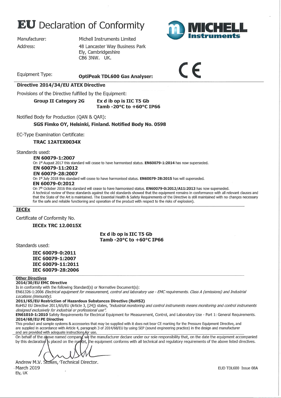
Page 87

Page 88

http://www.michell.com
 Loading...