

Page 1
S8000 RS
Chilled Mirror Hygrometer
User’s Manual
97315 Issue 9
April 2019
Page 2

Please ll out the form(s) below for each instrument that has been purchased.
Use this information when contacting Michell Instruments for service purposes.
Analyzer
Code
Serial Number
Invoice Date
Location of Instrument
Tag No
Analyzer
Code
Serial Number
Invoice Date
Location of Instrument
Tag No
Analyzer
Code
Serial Number
Invoice Date
Location of Instrument
Tag No
Page 3
S8000 RS
For Michell Instruments' contact information please go to
www.michell.com
© 2019 Michell Instruments
This document is the property of Michell Instruments Ltd. and may not be copied or
otherwise reproduced, communicated in any way to third parties, nor stored in any Data
Processing System without the express written authorization of Michell Instruments Ltd.
Page 4

S8000 RS User’s Manual S8000 RS User’s Manual
Contents
Safety ...............................................................................................................................vii
Electrical Safety ..........................................................................................................vii
Pressure Safety ...........................................................................................................vii
Toxic Materials ............................................................................................................ vii
Repair and Maintenance ..............................................................................................vii
Calibration ..................................................................................................................vii
Safety Conformity .......................................................................................................vii
Abbreviations .................................................................................................................... viii
Warnings .......................................................................................................................... viii
1 INTRODUCTION ................................................................................................1
1.1 Operating Principle ............................................................................................. 1
2 INSTALLATION ..................................................................................................3
2.1 Safety ................................................................................................................ 3
2.2 Unpacking the Instrument ................................................................................... 3
2.3 Transportation Clamp Removal ............................................................................ 4
2.4 Operating Requirements ..................................................................................... 5
2.4.1 Environmental Requirements ......................................................................... 5
2.4.2 Electrical Requirements ................................................................................. 5
2.5 Exterior Layout ................................................................................................... 6
2.6 Rear Panel Connections ...................................................................................... 8
2.6.1 Power Supply Input ....................................................................................... 8
2.6.2 Analog Output Connections ............................................................................ 9
2.6.3 Alarm Output Connections ........................................................................... 11
2.6.4 Remote PRT Probe ..................................................................................... 12
2.6.5 USB/Ethernet Communications Port Connector .............................................. 13
2.6.6 RS232/485 Port (optional) ........................................................................... 14
2.7 Conversion of S8000 RS to Rack Mount ............................................................. 15
2.7.1 Fitting Rack Mounted Version into Rack ........................................................ 16
3 OPERATION ....................................................................................................17
3.1 General Operational Information ........................................................................ 17
3.1.1 Sample Flow Adjustment ............................................................................. 17
3.2 Start-up procedure when measuring in flammable gases ..................................... 18
3.3 Instrument Display ........................................................................................... 18
3.3.1 Main Screen ................................................................................................ 19
3.3.2 Customizable Readouts................................................................................ 20
3.3.3 Operational Status Display ........................................................................... 21
3.3.4 Cooler Set up .............................................................................................. 22
3.3.5 Setup Menu Screen ..................................................................................... 23
3.3.6 Menu Structure .......................................................................................... 25
3.3.7 DCC ........................................................................................................... 26
3.3.8 LOGGING ................................................................................................... 27
3.3.9 OUTPUTS ................................................................................................... 29
3.3.10 ALARM ....................................................................................................... 29
3.3.11 DISPLAY .................................................................................................... 30
3.3.12 CLOCK ....................................................................................................... 31
3.3.13 ABOUT (Network Settings) ........................................................................... 31
3.4 Operational Functions ....................................................................................... 32
3.4.1 Operating Cycle .......................................................................................... 32
3.5 Operating Guide ............................................................................................... 33
3.5.1 Automatic Mode .......................................................................................... 33
iv 97315 Issue 9, April 2019
Page 5

3.5.1.1 Description ........................................................................................... 33
3.5.1.2 Operating Practice ................................................................................. 33
3.5.1.3 Flood Recovery ..................................................................................... 34
3.6 Manual Mode ................................................................................................... 34
3.6.1 Description ................................................................................................. 34
3.6.1.1 Operating Practice ................................................................................. 34
3.6.2 DCC - Dynamic Contamination Control .......................................................... 35
3.6.3 MAXCOOL Function ..................................................................................... 36
3.6.4 Pressure Input ............................................................................................ 36
3.6.5 Data Logging .............................................................................................. 36
3.6.6 Frost Assurance System Technology (FAST) .................................................. 37
3.6.7 STANDBY Mode........................................................................................... 37
4 APPLICATION SOFTWARE ................................................................................38
4.1 Installation ....................................................................................................... 38
4.2 Establishing Communications ............................................................................ 38
4.2.1 USB Communication .................................................................................... 39
4.2.2 Ethernet Communication ............................................................................. 40
4.3 Data Acquisition or Edit Variables Mode .............................................................. 41
4.3.1 Data Acquisition .......................................................................................... 42
4.3.2 Variable Edit ............................................................................................... 44
5 MAINTENANCE ................................................................................................46
5.1 Fuse Replacement ........................................................................................... 46
5.2 Sensor Mirror Cleaning ...................................................................................... 48
6 GOOD MEASUREMENT PRACTICE .....................................................................49
6.1 Sampling Hints ................................................................................................. 49
7 CALIBRATION ..................................................................................................52
7.1 Traceability ...................................................................................................... 52
Tables
Table 1 Front Panel Controls ....................................................................................6
Table 2 Rear Panel Connections ...............................................................................7
Table 3 Main Screen Description ............................................................................. 20
Table 4 Operational Status Display ........................................................................ 21
Table 5 Cooler Setup Parameters ............................................................................22
Table 6 Cooler Alarm Warnings .............................................................................. 22
Table 7 DCC Parameters ........................................................................................ 26
Table 8 Logging Parameters ................................................................................... 27
Table 9 SD Card Status Indicators ..........................................................................28
Table 10 Outputs Parameters ................................................................................... 29
Table 11 Alarm Parameters ......................................................................................29
Table 12 Display Parameters ....................................................................................30
Table 13 Clock Parameters .......................................................................................31
Table 14 Network Parameters ..................................................................................31
Table 15 Data Acquisition Control Description ...........................................................42
Table 16 Graph Control Description ..........................................................................43
Table 17 Status Bar Description ...............................................................................43
Table 18 Default Set-Up Parameters .........................................................................58
Table 19 Register Map ............................................................................................. 62
Michell Instruments v
Page 6

S8000 RS User’s Manual S8000 RS User’s Manual
Figures
Figure 1 Operating Principle .......................................................................................... 2
Figure 2 Rear clamp ..................................................................................................... 4
Figure 3 Front clamp .................................................................................................... 5
Figure 4 Front Panel ..................................................................................................... 6
Figure 5 Rear Panel ...................................................................................................... 7
Figure 6 Power Supply Input ......................................................................................... 8
Figure 7 Alarm and Analog Output Connection ............................................................. 10
Figure 8 Remote PRT Connection ................................................................................ 12
Figure 9 USB Port Connection ..................................................................................... 13
Figure 10 Ethernet Port ................................................................................................ 13
Figure 11 RS232/485 Port (optional) ............................................................................. 14
Figure 12 Conversion to Rack Mount ............................................................................. 15
Figure 13 Initialising Overlay Screen .............................................................................. 18
Figure 15 Main Screen Layout ....................................................................................... 19
Figure 14 Main Screen .................................................................................................. 19
Figure 16 Cooler Setup Screen ...................................................................................... 22
Figure 17 Setup Menu Screen ....................................................................................... 23
Figure 18 Virtual Keyboard .......................................................................................... 24
Figure 19 Menu Structure ............................................................................................. 25
Figure 20 DCC Screen .................................................................................................. 26
Figure 21 Logging Screen ............................................................................................. 27
Figure 22 Outputs Screen ............................................................................................. 29
Figure 23 Alarm Screen ................................................................................................ 29
Figure 24 Display Screen .............................................................................................. 30
Figure 25 Clock Screen ................................................................................................. 31
Figure 26 Network Settings Screen ................................................................................ 31
Figure 27 Typical Operating Cycle .................................................................................. 32
Figure 28 Communications Setup Screen ....................................................................... 38
Figure 29 Windows Device Manager Screen ................................................................... 39
Figure 30 Network Settings Screen ................................................................................ 40
Figure 31 Options Screen ............................................................................................. 41
Figure 32 Data Acquisition Screen ................................................................................. 42
Figure 33 Variables Editor Screen .................................................................................. 45
Figure 34 Fuse Replacement ......................................................................................... 46
Figure 35 Sensor Mirror Cleaning .................................................................................. 48
Figure 36 Material permeability comparison ................................................................... 49
Figure 37 Typical Calibration Certificate ......................................................................... 52
Figure 38 Operational Range......................................................................................... 55
Figure 39 S8000 RS Dimensions .................................................................................... 55
Appendices
Appendix A Technical Specifications ...................................................................................54
Appendix B Default Set-Up Parameters ...............................................................................58
Appendix C Modbus Holding Register Map ..........................................................................60
Appendix D Quality, Recycling & Warranty Information ........................................................68
Appendix E Analyzer Return Document & Decontamination Declaration ................................70
vi 97315 Issue 9, April 2019
Page 7
Safety
!
The manufacturer has designed this equipment to be safe when operated using the procedures
detailed in this manual. The user must not use this equipment for any other purpose than that
stated. Do not apply values greater than the maximum value stated.
This manual contains operating and safety instructions, which must be followed to ensure the safe
operation and to maintain the equipment in a safe condition. The safety instructions are either
warnings or cautions issued to protect the user and the equipment from injury or damage. Use
qualified personnel and good engineering practice for all procedures in this manual.
Electrical Safety
The instrument is designed to be completely safe when used with options and accessories supplied
by the manufacturer for use with the instrument. The input power supply voltage limits are 85 to
264 V AC, 47/63 Hz. Refer to Appendix A - Technical Specifications.
Pressure Safety
Before pressurizing, the user must ensure through appropriate
protective measures that the system or the device will not be over-
pressurized. When working with the instrument and pressurized gases
safety glasses should be worn.
DO NOT permit pressures greater than the safe working pressure to be applied to the instrument. The
specified safe working pressure is 10 barg (145 psig). Refer to Appendix A - Technical Specifications.
Application of gas pressures higher than the specified maximum will result in potential damage
and may render the instrument unsafe and in a condition of incorrect functionality. Only personnel
trained in the safe handling of high pressure gases should be allowed to operate this instrument.
Toxic Materials
The use of hazardous materials in the construction of this instrument has been minimized. During
normal operation it is not possible for the user to come into contact with any hazardous substance
which might be employed in the construction of the instrument. Care should, however, be exercised
during maintenance and the disposal of certain parts.
Repair and Maintenance
The instrument must be maintained either by the manufacturer or an accredited service agent. Refer
to www.michell.com for details of Michell Instruments’ worldwide offices contact information.
Calibration
The recommended calibration interval for the S8000 RS is one year, unless otherwise specified by
Michell Instruments Ltd. The instrument should be returned to the manufacturer, Michell Instruments,
or one of their accredited service agents for re-calibration (go to www.michell.com for contact
information).
Safety Conformity
This product meets the essential protection requirements of the relevant EU directives. Further
details of applied standards may be found in the product specification.
Michell Instruments vii
Page 8

Abbreviations
!
DANGER
Electric
Shock Risk
The following abbreviations are used in this manual:
DCC Dynamic Contamination Correction
FAST Frost Assurance System Technology
MAXCOOL Maximum Sensor Cooling
AC alternating current
atm pressure unit (atmosphere)
bar pressure unit (=100 kP or 0.987 atm)
°C degrees Celsius
°F degrees Fahrenheit
COM common
dp dew point
EU European Union
g/kg grams per kilogram
g/m3 grams per cubic meter
HMI Human Machine Interface
Hz Hertz
IEC International Electrotechnical Commission
Nl/min normal liters per minute
lb pound
mA milliampere
max maximum
min minute(s)
mV millivolt(s)
N/C normally closed
N/O normally open
No number
ppmV parts per million (by volume)
ppmW parts per million (by weight)
PRT Platinum resistance thermometer (typically type Pt100)
psig pound(s) per square inch (gauge)
rh relative humidity
RTU Remote Terminal Unit
scfh standard cubic feet per hour
SD storage device card (memory card for storing datalog files)
sec second(s)
temp temperature
USB Universal Serial Bus
V Volts
S8000 RS User’s Manual S8000 RS User’s Manual
Warnings
The following general warnings listed below are applicable to this instrument. They are
repeated in the text in the appropriate locations.
Where this hazard warning symbol appears in the following
sections, it is used to indicate areas where potentially hazardous
operations need to be carried out.
Where this symbol appears in the following sections it is used to
indicate areas of potential risk of electric shock.
viii 97315 Issue 9, April 2019
Page 9

1 INTRODUCTION
The S8000 RS is a high precision instrument used for the measurement of moisture
content in air and other gases. Relative humidity and other calculated parameters based
on dew point, pressure and temperature of the sample gas can also be displayed. Gases
can be sampled at a maximum pressure of 10 barg (145 psig).
The S8000 RS is capable of measuring dew points as low as -80°C or -90°C (-112°F or
-130°F) (depending on the model - RS80 or RS90); it can measure dew points up to
(but not including) the point of condensation.
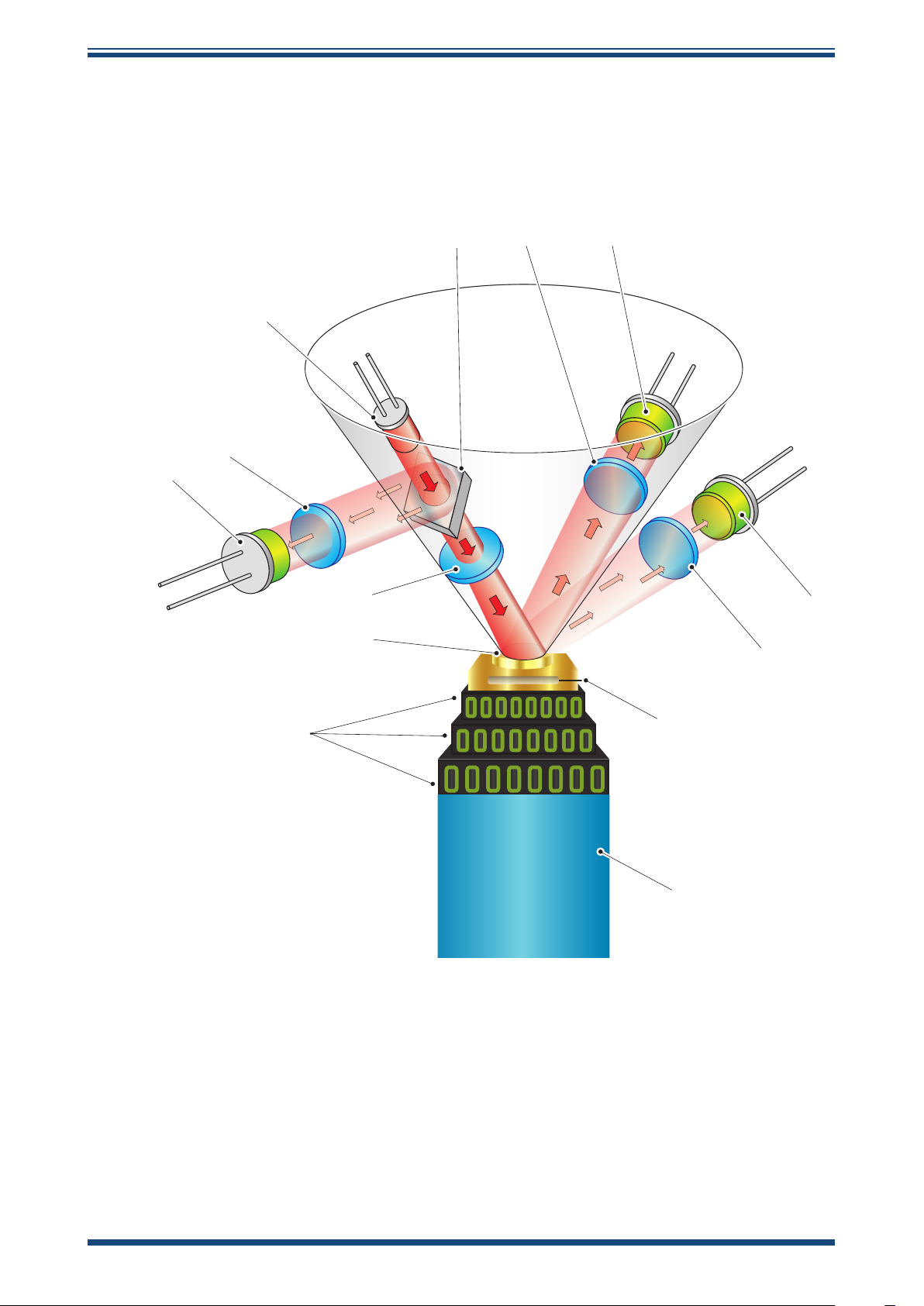
1.1 Operating Principle
The system operates on the chilled mirror principle, whereby a gas sample is passed
into the sensor housing and flows over the surface of the chilled mirror contained
within. At a temperature dependent upon the moisture content in the gas, and the
operating pressure, the moisture in the gas condenses out on the surface of the mirror.
INTRODUCTION
An optical system is used to detect the point at which this occurs, and this information
is used to control the mirror temperature and maintain a constant thickness of the
condensation layer on the mirror surface.
A light emitting diode (1) provides a light beam of constant intensity which is focused
by a lens system (2) to become the incident beam on the mirror surface (3), flooding it
with a pool of light.
Before the light beam reaches the mirror (3), a beam splitter (4) directs part of the
beam via a lens system (5) onto a sensor (6) which monitors the intensity of the LED
light and provides a feedback loop to keep this at a constant level.
Two sensors (7 and 8) monitor the light level reflected by the mirror. One of these
sensors (7) measures the light level due to the reflected incident beam and the other
(8) measures the degree of light scatter due to the formation of water/ice on the mirror
surface. Each sensor has its own optical lens system (9) and (10) to concentrate the
reflected light onto the sensor.
The output from each of these sensors is compared and then used to control the drive
to a Peltier heat pump (11). Dependant on the result of this comparison, the control
system will cause the heat pump (11) to either heat or cool the mirror (3) in order to
maintain the desired condensation film thickness on the mirror surface.
At an equilibrium point, where the evaporation rate and condensation rate on the surface
of the mirror are equal, the mirror temperature, read by a Pt100 platinum resistance
thermometer (12) embedded in the mirror, represents the dew point.
Michell Instruments 1
Page 10
INTRODUCTION
The ‘hot’ side of the Peltier is coupled to an auxiliary cooling system through a thermal
mass (13) – which smooths its response. The cooling system removes heat from the
hot side of the Peltier, by cooling it to an appropriate temperature. This supplements
the depression capabilities of the heat pump, and enables measurement of very low
dew points.
5
6
S8000 RS User’s Manual S8000 RS User’s Manual
94 7
1
11
2
3
Figure 1
8
10
12
13
Operating Principle
2 97315 Issue 9, April 2019
Page 11

2 INSTALLATION
!
2.1 Safety
It is essential that the installation of the electrical and gas
supplies to this instrument be undertaken by competent
2.2 Unpacking the Instrument
The S8000RS is a heavy instrument and should be unpacked by two people. Carefully
open the crate and check for any signs of transit damage before touching the instrument.
Remove the accessories before touching the instrument.
Carefully lift the unit out holding the case and not the foam as these may become loose
and allow the instrument to fall.
Ensure one person has a good grip of the unit whilst the other removes the foam
protectors:
INSTALLATION
personnel.
Save all the packing materials for the purpose of returning the instrument for
re-calibration or any warranty claims.
Failure to return the instrument in the original packing, or failure to return the instrument
with the transit clamp fitted may result in warranty claims being denied.
Michell Instruments 3
Page 12
INSTALLATION
The accessories crate should contain the following items:
• Traceable calibration certificate
• SD memory storage card
• USB or Ethernet communications cable
• IEC power cable
• Microscope
• Remote Pt100 temperature probe (optional)
• Optics cleaning kit (optional)
• 19" Rack mount kit (optional)
• Transport case (optional)
If there are any shortages please notify the supplier immediately.
S8000 RS User’s Manual S8000 RS User’s Manual
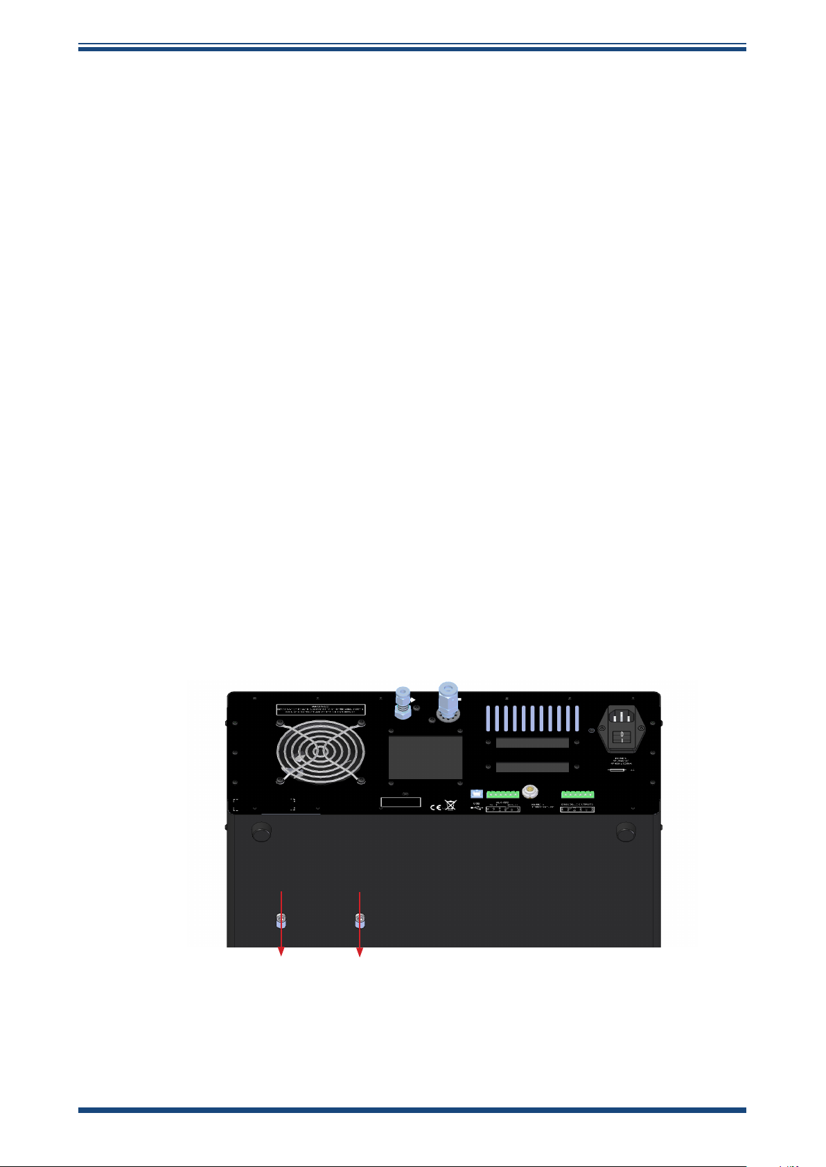
2.3 Transportation Clamp Removal
Prior to powering the instrument on, the transportation clamps must be removed. There
are two separate clamps:
1. Rear clamp
Carefully place the instrument on its side, with the sensor head side down.
As per Figure 3, there are two slots machined into the outer case. A bolt will be visible
through each.
Figure 2
Use a 5mm Allen key to loosen each bolt (do not try to remove them) and slide them
into the forward position in the slots. Re-tighten the bolts in this position so they cannot
move around.
Carefully place the instrument back onto its base.
Rear clamp
4 97315 Issue 9, April 2019
Page 13
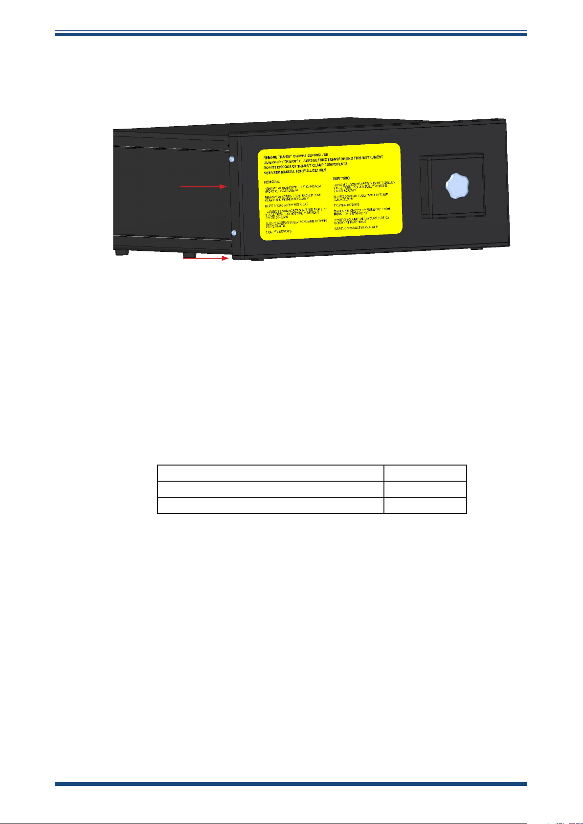
INSTALLATION
2. Front clamp
As per Figure 4, use a 3mm Allen key to remove the 2 bolts on either side of the front
clamp. Keep these bolts safe for future use.
Remove the microscope cover. The front clamp should now slide away from the
instrument.
2.4 Operating Requirements
2.4.1 Environmental Requirements
It is important to operate the S8000 RS within the following environmental conditions:
Minimum Operating Temperature 5°C
Maximum Operating Temperature 30°C
Maximum Relative Humidity 80%
2.4.2 Electrical Requirements
Figure 3
Front clamp
The S8000 RS requires the following electrical supply:
• 85 to 264 V AC, 47/63 Hz, 250 VA max
• Alarm outputs comprise two sets of changeover relay contacts, one set
for a PROCESS alarm and one set for an INSTRUMENT FAULT. Both sets
of contacts are rated at 24 V, 1A. NOTE: THIS RATING MUST NOT BE
EXCEEDED.
Michell Instruments 5
Page 14
INSTALLATION
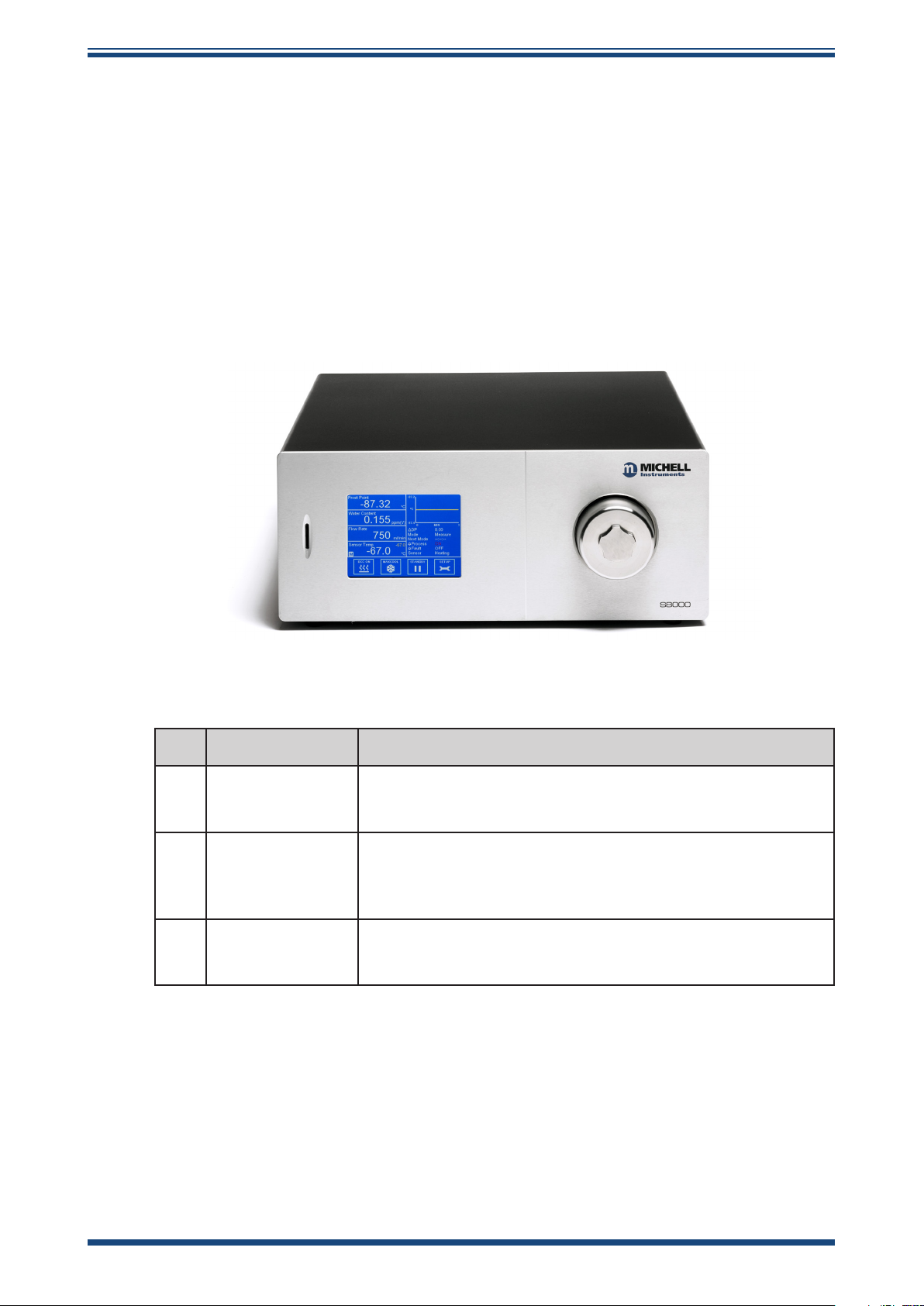
2.5 Exterior Layout
The controls, indicators and connectors associated with the S8000 RS are located on
the front and rear panels of the instrument.
The controls and indicators relating to the operator interface are located on the front
panel. The gas outlet, gas inlet, external PRT connection, mains power IEC socket,
analog output connector, remote temperature probe connector, alarm relay connector,
and the USB/RJ45 Ethernet socket are located on the rear panel.
Front Panel
S8000 RS User’s Manual S8000 RS User’s Manual
2
1
Figure 4
No Name Description
Takes an SD card used to store logged data
1 SD Card Slot
2
3 Sensor Housing
Touch Screen
Display
See Section 3.2.8 for more details on how to use the logging
features
Displays measured values and enables the user to control the
operation of the instrument
See Section 3.2 for information about the touch screen and
menu system
Exterior housing of the sensor
See Section 5.2 for instructions on how to remove the housing
and clean the mirror
3
Front Panel
Table 1
Front Panel Controls
6 97315 Issue 9, April 2019
Page 15
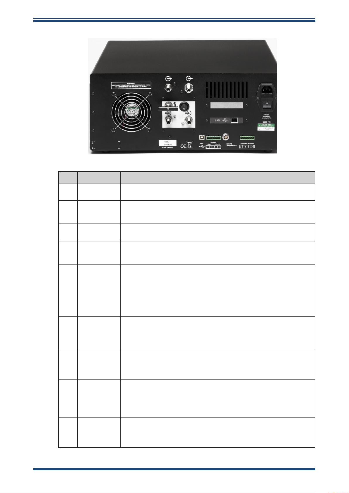
Rear Panel
INSTALLATION
Figure 5
No. Name Description
1
2
3
4
¼” Swagelok
Gas Outlet
¼” VCR Gas
Inlet
External PRT
Connection
Mains power
IEC Socket
6-Way
5
Analog
Output
Connector
Remote
6
Temperature
Probe
Connector
6-Way
7
Alarm Relay
Connector
RJ45
8
Ethernet
Socket
(Optional)
9 USB Type B
Connection for venting sample gas to atmosphere or vent line once it
has passed through the instrument
Connection for supplying the instrument with sample gas, usually at
a pressure slightly higher than atmospheric to maintain flow through
the instrument
Banana sockets for external 4-wire measurement of the internal PRT
See Section 3.2.11 for more info
Universal power input 85 to 264 V AC, 47/63 Hz
Fuse - 3.15 A, Anti-Surge, Glass, 20mm x 5mm
Features integrated power ON/OFF switch
Three configurable 2-wire channels providing 0-20 mA,
4-20 mA or 0 - 1 V output. The 0/4-20mA outputs are active (sourcing)
and must be connected to a passive (sinking) input on the receiving
equipment.
See Section 3.2.9 for instructions on how to configure the analog
outputs
See Section 2.5.2 for general information
6-Pin Lemo socket for connection of remote Pt100 temperature probe
Process and Fault alarm outputs
See Section 2.5.3 for general information on the alarm relays
See Section 3.2.10 for instructions on how to configure the process
alarm
Used for communication with the instrument over a network
connection
See Section 3.2.13 for details on how to configure the network settings
See Section 4.1 for information on using and installing the application
software
Used for communication with the instrument via the application
software
See Section 4.1 for information on using and installing the application
software
1 2
3
8
9
7
Rear Panel
4
6
5
Table 2
Rear Panel Connections
Michell Instruments 7
Page 16
INSTALLATION
!
DANGER
Electric
Shock Risk
2.6 Rear Panel Connections
These tasks should be undertaken only by competent
All the connections to the rear panel are electrical
Exercise due caution, particularly when connecting to
external alarm circuits which could be at high potential.
Connections to the rear panel of the instrument are explained in the following sections.
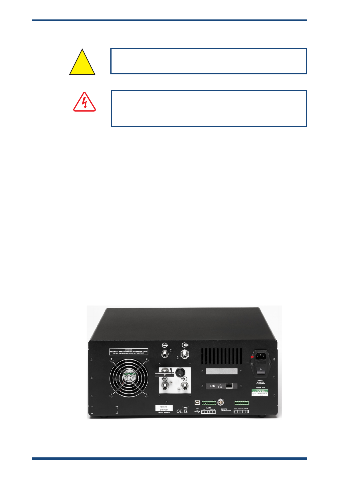
2.6.1 Power Supply Input
S8000 RS User’s Manual S8000 RS User’s Manual
personnel.
connections.
The AC power supply is a push fit into the power input socket as shown in
method of connection is as follows:
1. Ensure that both ends of the power cable are potential free, i.e. not
connected to an AC power supply.
2. Check that the ON/OFF switch (1) is switched to OFF.
3. Push the IEC connector (3) firmly into the power input socket (2).
4. Connect the free end of the power cable to a suitable AC power
supply source (voltage range 85 to 264 V AC, 47/63 Hz) and switch
on the AC supply. Switch on the instrument, as required, using the
power ON switch.
Figure 7.
The
Figure 6
Power Supply Input
8 97315 Issue 9, April 2019
Page 17

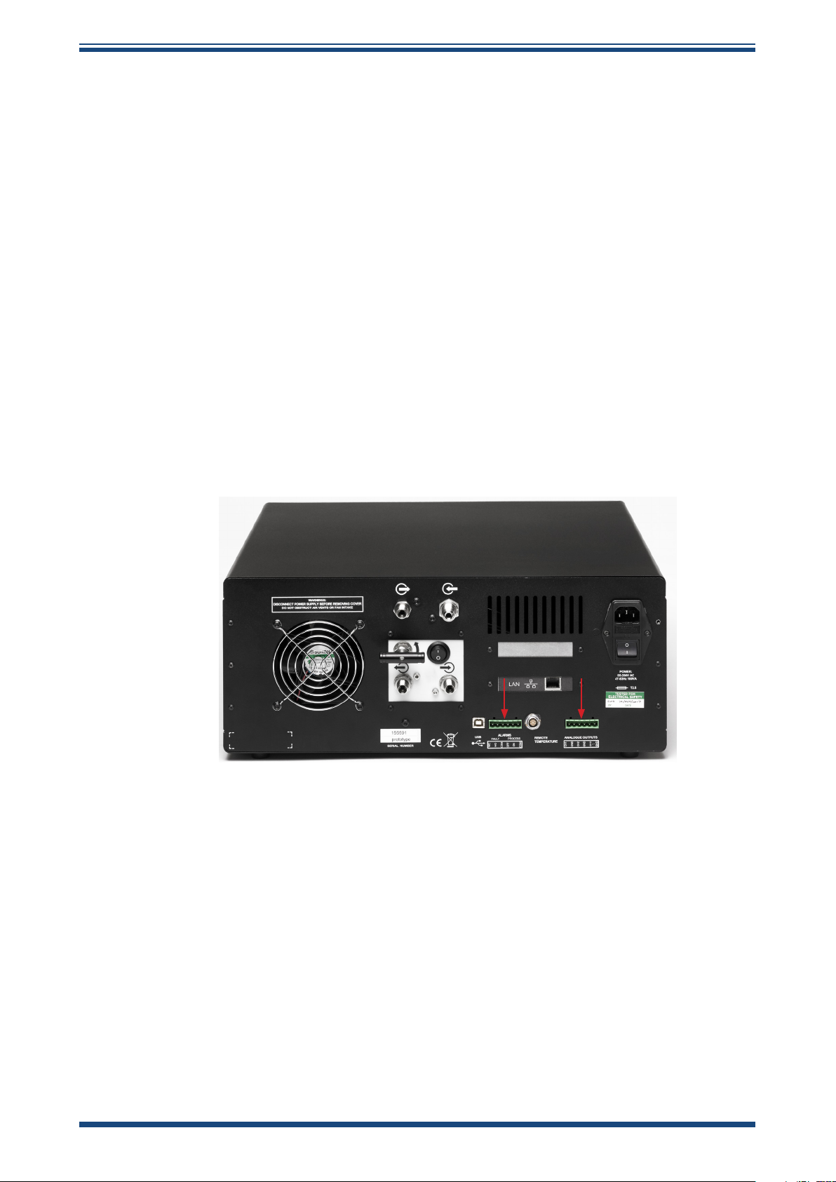
2.6.2 Analog Output Connections
The three analog outputs can be configured to represent any of the directly measured
or calculated output parameters. They are provided as 2-wire signals from a 6-way
connector located on the rear panel of the instrument
Each of these outputs can be set up as either a current loop signal (4-20 mA or 0-20 mA)
or alternatively, as a 0-1 V voltage signal. The 0/4-20mA outputs are active (sourcing)
and must be connected to a passive (sinking) input on the receiving equipment. The
configuration of these outputs, i.e. parameter represented, output type (current loop
or voltage) and upper/lower span levels are set up via the Setup Menu Screen (refer to
Section 3.2.9).
These signals may be used to control external systems. During a DCC cycle, and for
the hold period following a DCC cycle, they are held at the level that they were at
immediately prior to the start of the cycle. When the dew-point measurement is stable,
or if the maximum hold period has expired, they are released and will track the selected
parameter throughout the measurement cycle.
The default settings of these analog outputs are:
INSTALLATION
.
Channel 1: Dew point, -80 to +20ºC
Channel 2: ppmV, 0 to 3000
Channel 3: Flow, 0 to 1000ml/min
NOTE: The analog outputs are only active during the MEASURE phase. They
will, therefore, be off after switch-on and remain off until the system enters
the MEASURE phase.
The three analog output ports connections are made via a single, 6-way, push fit
connector block as shown in
referenced to a common 0 V line. To differentiate between the outputs it is recommended
that a black lead be used for each of the COM (common) lines and a separate color for
each of the positive lines.
Figure 8
. All outputs are 2-wire, positive-going signals
Michell Instruments 9
Page 18
INSTALLATION
For each output:
1. Remove the terminal block fitted into the analog output socket.
2. Strip back the wire for the common (black) connection to the
CH1 output, exposing approximately 6mm (0.25"). Insert the wire
into the COM1 terminal way and screw into the block. Do not
overtighten the screw.
3. Strip back the wire for the signal (e.g. red) connection to the
OP1 output, exposing approximately 6mm (0.25"). Insert the
wire into the OP1 terminal way and screw into the block. Do not
overtighten the screw.
4. Repeat operations 1 and 2 for the other analog outputs, selecting a
different color wire for the OP2 and OP3 outputs.
5. Locate the terminal block over the connector labelled ANALOG
OUTPUTS and push the terminal block firmly into the connector.
S8000 RS User’s Manual S8000 RS User’s Manual
Figure 7
Alarm and Analog Output Connection
10 97315 Issue 9, April 2019
Page 19
2.6.3 Alarm Output Connections
DANGER
Electric
Shock Risk
Two alarm outputs are provided from a terminal block, located on the rear panel of
the instrument, as two pairs of potential free, change-over relay contacts. These are
designated as a PROCESS alarm and a FAU LT alarm.
Under the Setup Menu Screen, (refer to Section 3.2.5), the PROCESS alar m can be config ured
to represent any one of the measured or calculated parameters and set up to operate when
a pre-set parameter threshold level is exceeded. By default, the PROCESS alarm is set to
monitor the dew-point parameter.
The FAU LT alarm is a non-configurable alarm which continuously monitors the degree
of contamination of the chilled mirror. During normal operational conditions, this alarm
will be off. If the optics or the mirror contamination exceeds 100% of the film thickness,
or if a fault exists on the Pt100, the alarm is triggered and the relay contacts will change
state.
This fault is also reported to the status area of the Main Screen.
The two alarm output ports are connected to the instrument via a single 6-way, push-fit
connector block as shown in
free, change-over relay contacts.
Figure 8
INSTALLATION
. Each output comprises a 3-wire set of potential
Each contact set is labelled COM (common 0 V), N/O (normally open with respect to
COM) and N/C (normally closed with respect to COM).
To differentiate between the alarm output channels, it is recommended that a black lead
is used for each of the COM (common) lines and a separate color for each of the N/O
and N/C lines.
WARNING: Alarm leads MUST be potential free when wiring
to the connector block. Both sets of contacts are rated at 24
V, 1A. THIS RATING MUST NOT BE EXCEEDED.
For each output:
1. Strip back the wire for the common (black) connection to the
COM connector way for the FAU LT alarm contact set, exposing
approximately 6mm (0.25") wire. Clamp into the screw block COM
terminal way. Do not overtighten the screw.
2. Strip back the wire for the N/O (e.g. green) connection to the
N/O connector way for the FAU LT alarm contact set, exposing
approximately 6mm (0.25") wire. Clamp into the screw block N/O
terminal way. Do not overtighten the screw.
3. Strip back the wire for the N/C (e.g. blue) connection to the
N/C connector way for the FAULT alarm contact set, exposing
approximately 6mm (0.25") wire. Clamp into the screw block N/C
terminal way. Do not overtighten the screw.
Michell Instruments 11
Page 20
INSTALLATION
4. Repeat operations 1 to 3 for the PROCESS alarm contact set, using
appropriately colored wires.
5. Locate the terminal block over the connector labelled ALARMS and
push the terminal block firmly into the connector.
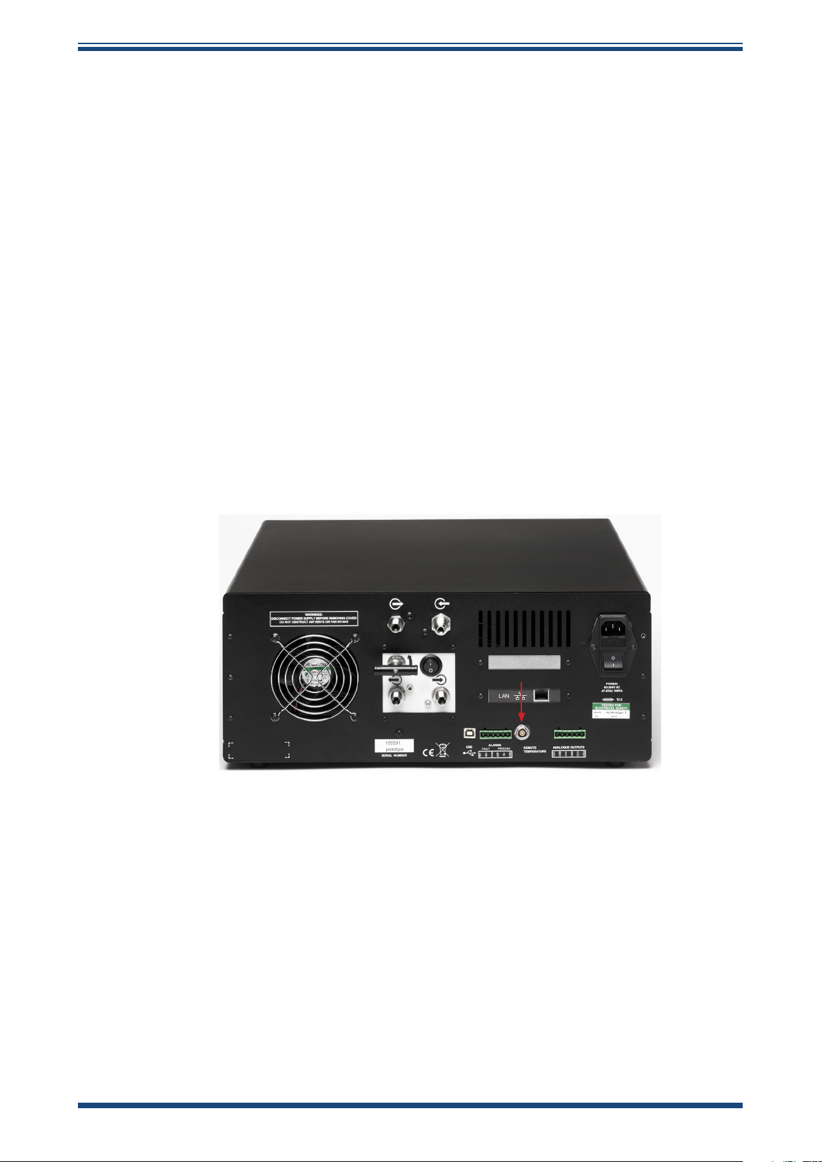
2.6.4 Remote PRT Probe
1. Rotate the body of the PRT probe connector until it locates in the
socket labeled REMOTE TEMPERATURE (see
2. Push the connector into the socket until it locks. NOTE: Do not
attempt to force it into the socket. If it does not fit in, rotate
it until the key locks and it pushes in easily.
3. To remove the connector, slide the connector’s body collar (1) back
along its axis, away from the instrument, to release the lock. Gently
pull the connector body out of the socket. NOTE: Do not attempt
to pull the connector out with the cable - make sure that
the collar is first released.
S8000 RS User’s Manual S8000 RS User’s Manual
Figure 9).
Figure 8
Remote PRT Connection
12 97315 Issue 9, April 2019
Page 21
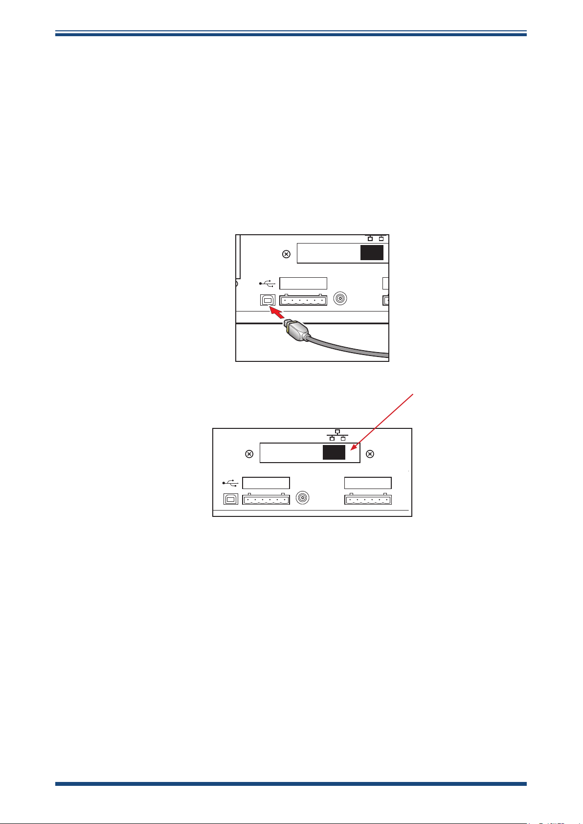
2.6.5 USB/Ethernet Communications Port Connector
CH1
GND
CH2
GND
CH3
GND
ANALOGUE OUTPUTS
LAN
REMOTE SENSOR MEASUREMENT
CALIBRATION CURRENT = 1mA
PT100
1 2 3 4
1
The instrument features a USB port and an optional Ethernet port for communication
with the application software. The appropriate cable will be supplied with the instrument.
1. Check the orientation of the connector and gently push it into the
communications socket (see
Figures 10 and 11)
2. To remove the connector, pull it out of the socket by holding the
connector body. If using an Ethernet cable there will be a small
locking tab that needs to be depressed in order to release the
connector. Do not attempt to remove the connector from the
socket by pulling on the cable.
ALARMS
FAULT PROCESS
USB
N/C
ON
OFF
N/O
COM
COM
.
REMOTE
TEMPERATURE
INSTALLATION
Figure 9
ALARMS
FAULT PROCESS
USB
N/C
N/O
Figure 10
COM
USB Port Connection
LAN
REMOTE
TEMPERATURE
ON
OFF
COM
Ethernet Port
ANALOGUE OUTPUTS
CH1
CH2
GND
GND
CH3
GND
USB Connection
The application software includes a virtual serial port driver allowing the customers own
software to be used with the device. The communications protocol used is Modbus RTU.
Refer to Appendix C for the Modbus register map.
Ethernet Connection
Appendix C for the Modbus register map.
Michell Instruments 13
The communication protocol used with the Ethernet port is Modbus TCP. Refer to
Page 22
INSTALLATION
N/C
N/O
COM
OFF
ON
COM
CH1
GND
CH2
GND
CH3
GND
ALARMS
FAULT PROCESS
ANALOGUE OUTPUTS
REMOTE
TEMPERATURE
RS232
USB
REMOTE SENSOR MEASUREMENT
CALIBRATION CURRENT = 1mA
PT100
1 2 3 4
1
5
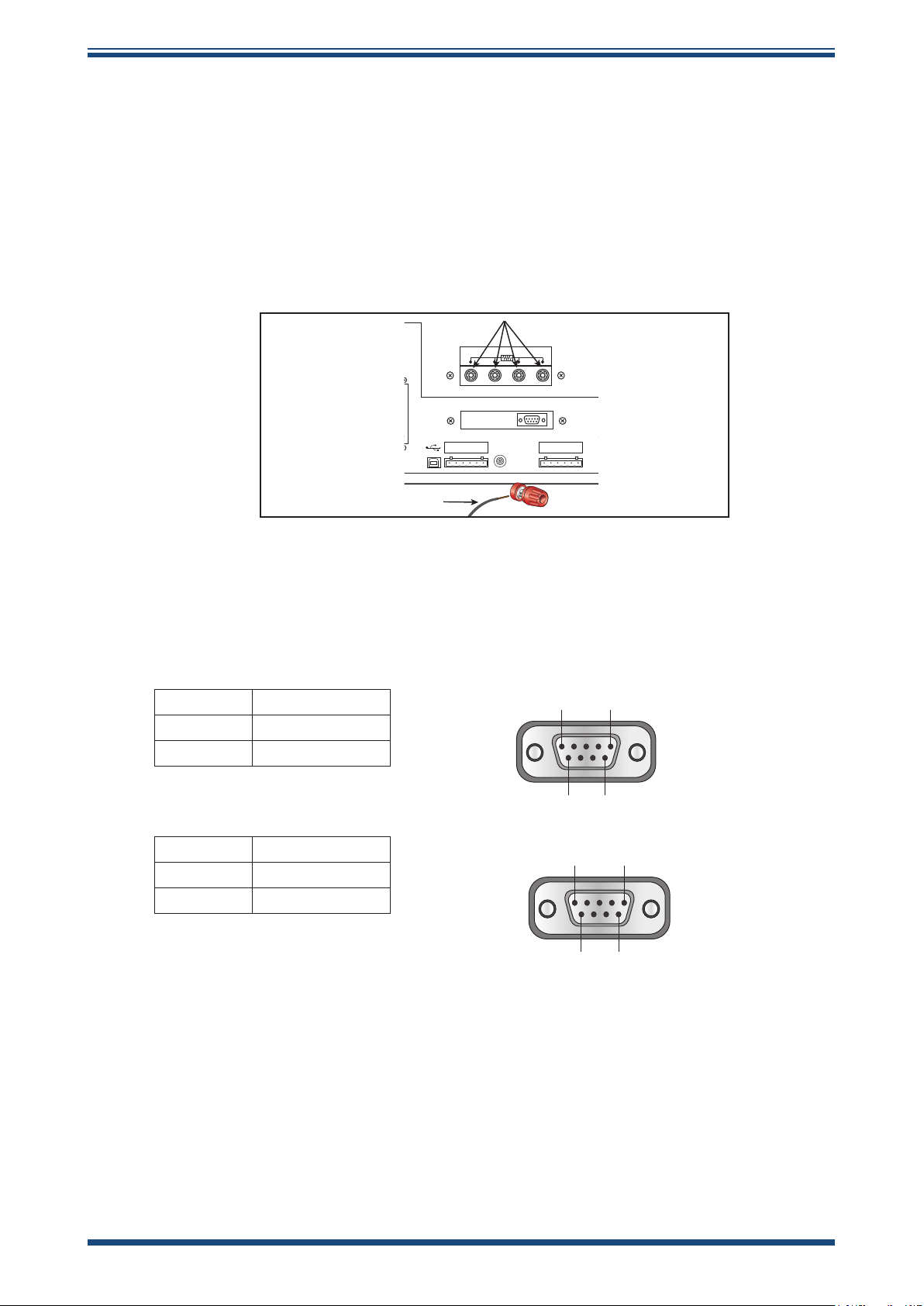
2.6.6 RS232/485 Port (optional)
The instrument features an optional RS232/485 port for communication with the
application software. This is designed to be used with a standard 9-pin D-sub connector.
The communications protocol used is Modbus RTU. Refer to Appendix C for the Modbus
register map.
1. Check the orientation of the connector and gently push it into the
socket labelled RS232 or RS485, and tighten the retaining screws.
S8000 RS User’s Manual S8000 RS User’s Manual
Figure 11
RS232/485 Port (optional)
2. Loosen the retaining screws, and pull the connector out of the
socket by holding the connector body.
RS232
Pin 2 TXD
RS232 Pinout (9-pin female)
Pin 1
Pin 5
Pin 3 RXD
Pin 5 GND
RS485
Pin 3 A
Pin 6
RS485 Pinout (9-pin female)
Pin 1
Pin 9
Pin 5
Pin 5 GND
Pin 8 B
Pin 6
Pin 9
14 97315 Issue 9, April 2019
Page 23
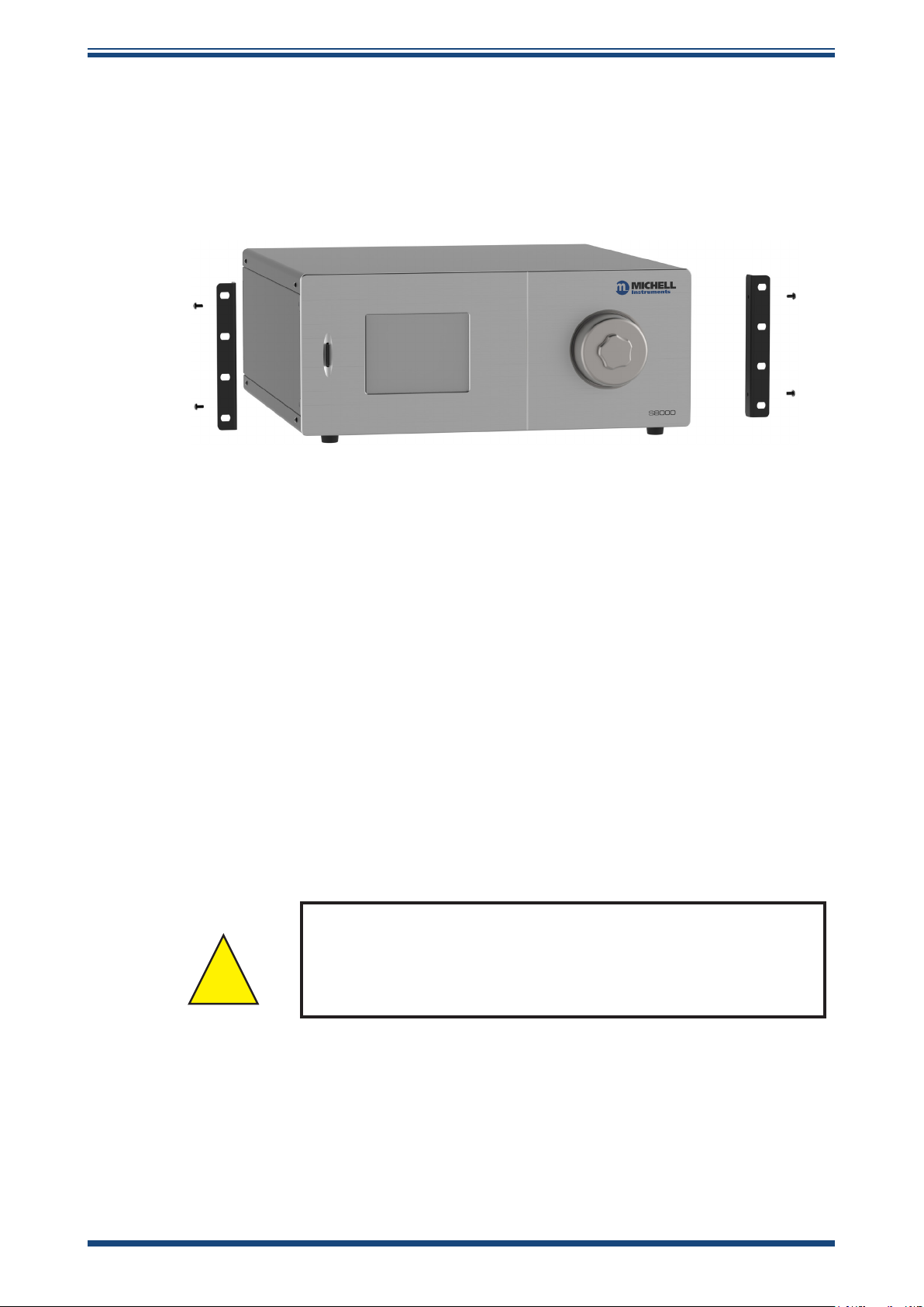
2.7 Conversion of S8000 RS to Rack Mount
!
To convert an S8000 RS to a rack mounted version, a rack mounting kit (Part No.
S8K401-PKI) is required. This conversion pack comprises two steel wings and four rack
mounting screws and washers. Each wing bolts to the side of the instrument with four
screws (already in the instrument) as shown in
Figure 13.
INSTALLATION
Figure 12
1. Turn the unit on its left hand end and remove the four screws and
washers from the side panel.
2. Line up the fixing holes on the right hand side of the instrument
with the corresponding holes in the right hand wing (flange facing
outwards).
3. Insert the four screws and washers through the wing and tighten
finger tight.
4. Ensure that the front flange is square to the front of the instrument
and tighten the screws.
5. Turn the unit on its right hand end and repeat operations 1 to 4.
To remove the rack support wings remove the unit from the rack (if necessary) and
follow the directions above, in reverse.
NOTE: The rack mounting wings are designed to hold the
unit into the rack, not to support its full weight.
The instrument should be placed onto a shelf or rails
Conversion to Rack Mount
Michell Instruments 15
Page 24

INSTALLATION
2.7.1 Fitting Rack Mounted Version into Rack
1. Remove the connector blocks from the alarm and analog output
sockets.
2. If necessary, remove any covers from the rack cabinet to gain
access to the rear and side.
3. Connect up the analog and alarm output connector blocks to
the internal rack wiring (refer to Section 2.5.2 & Section 2.5.3),
ensuring that there is sufficient free cable to permit withdrawal of
the instrument from the rack.
4. Slide the instrument into the rack and onto the correctly positioned
shelf or rails. Insert the four rack mounting screws and washers.
5. Ensure that the front panel of the instrument is flush and square
with the front of the rack and tighten the fixing screws.
6. Connect the sample pipework to the gas inlet, and the vent line to
the gas outlet, as required.
S8000 RS User’s Manual S8000 RS User’s Manual
7. Insert the analog and alarm connectors into their respective sockets
on the rear of the instrument (refer to
external PRT probe and USB communications cable and connector
as appropriate.
8. Connect the power supply cable and switch the ON/OFF switch to
Figure 8)
and connect the
ON.
9. Refit any covers to the rack as necessary.
To remove from the rack follow the directions above, in reverse.
16 97315 Issue 9, April 2019
Page 25

3 OPERATION
As supplied, the S8000 RS is ready for operation and a set of default parameters has
been installed. This section describes both the general operation of the instrument and
the method of setting it up and changing the default parameters (see Section 3.2.5)
should this become necessary.
3.1 General Operational Information
While the instrument can physically operate in a flowing gas stream of between 500 and
1000 ml/min (1 and 2.1 scfh), Michell Instruments recommends operating at 750 ml/min
(1.6 scfh), which is the flow-rate used during calibration. Operating at an alternative
rate could impact the instrument’s response time.
The sample inside the sensor is passed over a Peltier chilled, gold-plated mirror. The
instrument controls the mirror temperature to a point where a level of condensate is
maintained on the mirror surface. The temperature of the mirror is then measured as
the dew point.
OPERATION
The S8000 RS is suitable for the measurement of moisture content in a wide variety of
clean, non-corrosive gases. It will not contaminate high purity gases and is safe for use
in critical semi-conductor and fiber optic manufacturing applications.
3.1.1 Sample Flow Adjustment
• The sample flow is measured by the internal flow meter installed
into the sample line - preferably after the dew-point sensor.
• The recommended flow setting is 750 ml/min (1.6 scfh).
• The sample flow can be adjusted by the installation of a needle
valve in the sample line. If a pressurized sample is to be measured
at atmospheric pressure, the needle valve needs to be installed
and adjusted upstream of the sensor. For measurements at sample
pressure, the flow adjustment should be made downstream of the
sensor.
Michell Instruments 17
Page 26

OPERATION
S8000 RS User’s Manual S8000 RS User’s Manual
3.2 Start-up procedure when measuring in flammable gases
The S8000RS has a migration path to prevent condensation occurring in the area
immediately surrounding the thermo-electric cooler. In order to prevent a potentially
explosive mixture forming in this area as the flammable sample gas combines with the
residual air, the instrument should be purged prior to operation.
This can be achieved in one of two ways:
1. With inert gas for a minimum of 8 hours at the normal sample flow
rate of 750ml/min. The instrument does not need to be powered on
while this purge is in progress.
2. With the flammable sample gas for a minimum of 8 hours at the
normal sample flow rate of 750ml/min. The instrument MUST BE
POWERED OFF while this purge is in progress.
3.3 Instrument Display
The S8000 RS features a 5.7” color touch screen display.
When the instrument is switched on an Initialising overlay will be shown while the
menu system loads.
Figure 13
Initialising Overlay Screen
After the menu system has loaded, the Main Screen will show.
18 97315 Issue 9, April 2019
Page 27

OPERATION
748
25.01
-79.92
-79.5
-80.5
-60.0
-60.0
A
3.3.1 Main Screen
Figure 14
1
1
1
2
5 6 7 8
DCC OFF /
DCC ON
READOUTS
READOUTS
READOUTS
SENSOR TEMP
READOUT
MAXCOOL /
MEASURE
Figure 15
Main Screen
3
4
OPERATIONAL
STATUS DISPLAY
STANDBY /
OPERATE
Main Screen Layout
STABILITY
GRAPH
SET UP
Michell Instruments 19
Page 28

OPERATION
No Name Description
S8000 RS User’s Manual S8000 RS User’s Manual
1 Readouts
(Customizable)
2 Sensor Temperature
Readout
These readouts display measured instrument parameters
See Section 3.3.2 for additional information
This readout primarily shows the measured sensor body
temperature
The sensor body temperature set-point is displayed in
yellow in the top right of the readout
The cooler mode of operation - automatic or manual - is
indicated by a small A or M
See Section 3.3.4 for cooler setup parameters
Touch the readout once to display the cooler setup menu
The instrument will indicate when flood recovery is active
by means of a yellow FR (Flood recovery) warning icon
displayed in the sensor temperature window. The sensor
status indicator will also show FR in red text. See section
3.5.1.3 for further information.
3 Stability Graph Displays a plot of the dew point over time
Touch the readout once to enter full screen mode
4 Operational Status
Display
5 DCC Button Initiate a DCC cycle. See Section 3.4 for a detailed
6 MAXCOOL Button Toggle MAXCOOL mode. See Section 3.6.2 for a detailed
7 STANDBY Button Switch between Measure and Standby mode
8 SETUP Button Access to the Setup Menu
A detailed description of each item displayed in this area
is in Section 3.3.3
explanation of the DCC function
See Section 3.3.7 for DCC setup parameters
explanation of the MAXCOOL function
When switching to Measure mode a DCC cycle will be
initiated
See Section 3.6.6 for a detailed explanation of standby
mode
See Section 3.3.5 for more information about the setup
menu system
Table 3
3.3.2 Customizable Readouts
The three readouts on the Main Screen can be configured by the user to show any of
the following parameters:
• Dew point
• Temperature
• Temperature – Dew point
• Relative Humidity, %RH
• Water Content (ppmV; ppmW; g/kg; g/m3)
• Pressure *
• Flow
* Pressure is only available as an option if a pressure transducer is installed in the
instrument
The parameters displayed by default are Dew point, Water Content (ppmV) and Flow.
Main Screen Description
20 97315 Issue 9, April 2019
Page 29

Follow these instructions to change the parameter:
1. Touch the readout once to enable parameter selection
2. Touch the left or right arrows to select the parameter to be displayed
3. Touch the center of the readout to confirm selection
Full Screen Mode
Any of the readouts can be shown in full screen mode by touching and holding the
readout.
3.3.3 Operational Status Display
The Operational Status display includes the following:
Indicates data logging is enabled. Refer to Sections 3.2.8 and 3.4.6
OPERATION
∆DP Represents the change in dew point over the stability time of the graph
Mode Reports current operational mode
This will either be Measure, Standby, DCC, Hold or Maxcool
Next Mode Shows the time (in Hours: Minutes: Seconds) remaining until the transition
to the next mode of operation
Process
Fault Used to monitor the optical system and the degree of mirror contamination
Sensor Indicates the operational mode of the sensor
This two-state, ON/OFF notification indicates whether a parameter process
alarm is either ON or OFF
The process alarm can be set on any parameter (refer to Section 3.2.10)
During normal operation, with no fault conditions, this will read OFF. It
will be set to ON if there is either a fault with the optics or dp temperature
measurement or if the mirror contamination exceeds 100% of the film
thickness
This can be either CONTROL, HEATING or COOLING
Table 4
Operational Status Display
Michell Instruments 21
Page 30

OPERATION
3.3.4 Cooler Set up
The Cooler Setup screen is accessed by touching Sensor Temp readout on the Main
Screen. Refer to Section 3.4.2 for detailed information on the operation of the sensor
cooling system.
S8000 RS User’s Manual S8000 RS User’s Manual
System Temperature: OFF
Input out of range: OFF
System Shutdown: OFF
Figure 16
Parameter Description
Set-point Controls the sensor temperature
Mode Changes between Automatic and Manual cooler control
Table 5
In manual mode the cooler set-point must be maintained higher than the dew-point of
the applied gas. A margin of at least 10°C is recommended.
Cooler Alarm
Warnings
System
Temperature
Input out of
range
System
Shutdown
Description
Cooler heat-sink close to maximum safe temperature
The environmental temperature may be too hot, or the fan may have
stopped operating
Continuing to operate the S8000 RS without addressing this problem
may cause the cooler to overheat
Hardware fault
Contact Michell Instruments' service department
Cooler has been automatically disabled to prevent damage
May be caused by overheating, power supply problem or other safety
issue
Cooler Setup Screen
Cooler Setup Parameters
Table 6
Cooler Alarm Warnings
22 97315 Issue 9, April 2019
Page 31

3.3.5 Setup Menu Screen
The Setup Menu is used to adjust the operational parameters of the instrument, change
the display setup and start or stop the data logging feature.
Initially, when the Setup Menu Screen is opened, a set of labelled icons is displayed.
Touching one of these icons will take you to the appropriate submenu.
OPERATION
Figure 17
Once a submenu has been entered, parameters can be changed by touching the outlined
values. There are three types of input for editable values:
• Toggle Button – Touching the outlined value will switch between predefined
states, i.e. On/Off or Auto/manual
• List Selection – A list of options will be displayed for the user to select
• Numeric Input – Touching the outlined value will bring up the numeric
keypad (see following page)
Setup Menu Screen
Michell Instruments 23
Page 32

OPERATION
Numeric Input
When entering a numeric value a virtual keypad will be displayed.
S8000 RS User’s Manual S8000 RS User’s Manual
7 8 9
4
1
5 6
2 3
0
Figure 18
Virtual Keyboard
C
OK
The allowable range will initially be shown at the top of the keypad, e.g. 0 50
Some parameters can be disabled by entering a value of 0, this will be indicated by
0[off] 50
•
• Backspace
• Cancel input
•
Leaving Menus
To return from a menu or to cancel a numeric input, touch the exit icon.
24 97315 Issue 9, April 2019
Clear Input
C
OK
Save input
Page 33

3.3.6 Menu Structure
OPERATION
READOUTS
STABILITY
GRAPH
READOUTS
READOUTS
OPERATIONAL
STATUS DISPLAY
SENSOR TEMP
READOUT
DCC
Display Hold
Period
Reset Optics
Setpoint
Interval
Output Hold
LOGGING
Status
Filename
Interval
DCC OFF /
DCC ON
Output Select
Output Type
Parameter
Minimum
Maximum
OUTPUT
MAXCOOL /
MEASURE
ALARM
Parameter
Setpoint
STANDBY /
OPERATE
DISPLAY
Resolution
Primary Unit
Pressure Unit
Stability
FAST
PRT Mode
Language
Backlight
SET UP
CLOCK ABOUT HELP
Date
Time
Network Settings
IP Address
Subnet Mask
Default Gateway
Press to return to
Press for more
?
Main Page
information
Figure 19
Menu Structure
Michell Instruments 25
Page 34

OPERATION
3.3.7 DCC
S8000 RS User’s Manual S8000 RS User’s Manual
Figure 20
Parameter Description
Display Hold
Period
Reset Optics Triggers a reset of the optical signal level on the next DCC cycle
Setpoint
Interval
Output Hold
Holds the values on the display while the instrument is in HOLD mode
Available Input: On/Off
Duration of the DCC cycle
Available Input: 1 to 59 minutes
Mirror heating temperature above measured dew point during DCC cycle
Available Input: 10 to 40°C (50 to 104°F)
Time between automatic DCC cycles
Available Input: 1-99 hours. Set to 0 to disable automatic DCCs
Time to hold the output at the last measured value after finishing a DCC
cycle
Available Input: 1 to 59 minutes
Table 7
DCC Screen
DCC Parameters
26 97315 Issue 9, April 2019
Page 35

3.3.8 LOGGING
OPERATION
Figure 21
Parameter Description
Status Displays the status of the current logging operation
Filename Displays the filename of the current log file
Interval
SD Card Icon Shows the SD card status - refer to Table 9
START/STOP
Button
Time in seconds between recording readings in the log file
Available Input: 5 to 600 seconds
Automatically generates a new file name based on current time and
date - Starts logging at specified interval
Table 8
Logging Screen
Logging Parameters
Michell Instruments 27
Page 36

OPERATION
The table below explains the status of the SD card. The icon is shown in the bottom left
hand corner of the Logging screen.
S8000 RS User’s Manual S8000 RS User’s Manual
Icon Description
SD Card not fitted
Insert SD Card
Initializing SD Card
Wait before attempting to start logging
110001
010001
001011
SD Card ready to start logging
SD Card locked/write protected
Remove the SD Card and set the write-protect switch on the top left
side of the card to the UP position
Information being transferred to the SD Card
Do not remove the SD Card or power off the instrument
Logging in progress
Do not remove the SD Card or power off the instrument
SD Card error
Check the card is formatted correctly (FAT-32)
Hardware error
Contact Michell Instruments' service department
Table 9
SD Card Status Indicators
28 97315 Issue 9, April 2019
Page 37

3.3.9 OUTPUTS
OPERATION
0
Parameter Description
Output Select
Output Type
Selects the output to be adjusted
Available Input: Output 1, 2 or 3
Selects the type of analog output signal to use
Available Input: 4-20 mA/0-20 mA/0-1 V
The parameter used to control the selected output
Parameter
Available Input: g/m3, g/kg, T-DP, DP, %RH, ppmV, ppmW, T, psig,
barg, kPa, MPa, ml/min
Minimum
Maximum
The minimum output range for the selected parameter
Available Input: Dependent on parameter
The maximum output range for the selected parameter
Available Input: Dependent on parameter
Table 10
% RH
Figure 22
100
Outputs Screen
Outputs Parameters
3.3.10 ALARM
Parameter Description
Parameter
Setpoint
Figure 23
Alarm Screen
The parameter used to control the alarm
Available Input: g/m3, g/kg, T-DP, DP, %RH, ppmV, ppmW, T, psig,
barg, kPa, MPa, ml/min
Set point that triggers the alarm relay to activate. The alarm is a HIGH
alarm that triggers when the selected parameter exceeds the setpoint.
Available Input: Dependent on parameter
Table 11
Alarm Parameters
Michell Instruments 29
Page 38

OPERATION
3.3.11 DISPLAY
S8000 RS User’s Manual S8000 RS User’s Manual
Parameter Description
Number of decimal places used when displaying parameters on the
Resolution
Primary Unit
Pressure Unit
Stability
FAST
PRT Mode
Language
Backlight
Main Screen
Available Input: 1, 2, 3
Temperature unit to be used on the display and menus
Available Input: ºC / ºF
Pressure unit to be used on the display and menus
Available Input: psig, barg, kPa, MPa
Time scale in minutes for the Stability Graph on the Main Screen
Available Input: 1 to 600 minutes
Enables or disables the Frost Assurance System Technology.
See Section 3.4.7
Available Input: OFF / ON
If required for the calibration process or for external monitoring, the
internal PRT can be made available for external connection via the 4
banana sockets on the back of the instrument
Please note that this will disable the internal PRT measurement circuit
of the instrument
Available Input: INTERNAL / EXTERNAL
Selects the language used for the menu screens
Available Input: English / Deutsch / Español / Francais / Italiano /
Português / USA / Russian / Chinese
The brightness of the backlight
Available Input: 5 to 100%
Figure 24
Display Screen
Table 12
Display Parameters
30 97315 Issue 9, April 2019
Page 39

3.3.12 CLOCK
192
255
168
255
1
1 1
255
2
0
168192
OPERATION
Parameter Description
Date Current date
Time Current time
3.3.13 ABOUT (Network Settings)
When using an S8000 RS that is fitted with an Ethernet module this page is accessible
via the About Screen.
Figure 25
Table 13
Clock Screen
Clock Parameters
Figure 26
Network Settings Screen
Parameter Description
IP Address The IP address of the instrument
Subnet Mask The subnet mask that determines what subnet the IP address is on
Default
Gateway
The default gateway for network communication
Table 14
Network Parameters
Michell Instruments 31
Page 40

OPERATION
3.4 Operational Functions
3.4.1 Operating Cycle
S8000 RS User’s Manual S8000 RS User’s Manual
The default parameters set up for the instrument define an operating cycle, see
Figure
28.
Figure 27
At initial switch-on, the instrument enters a DCC cycle for 2 minutes. This heats the
mirror 20°C (36°F) above the previously measured value - at the time of switch on this
will be ambient temperature. This ensures that all moisture is driven off the surface of
the mirror.
Typical Operating Cycle
The mirror is maintained at this temperature for the DCC duration (default 4 minutes) or
2 minutes on switch-on. During the DCC process, Data Hold fixes the analog outputs at
the value(s) read before DCC commenced. Data Hold typically lasts 4 minutes from the
end of a DCC cycle, or until the instrument has reached the dew point. This procedure
is in place to prevent any system which is connected to the outputs from receiving a
'false' reading.
After the DCC period has finished, the measurement (MEASURE) period commences,
during which the control system decreases the mirror temperature until it reaches the
dew point. The sensor will take a short amount of time to settle on the dew point. The
length of this stabilization time depends upon the temperature of the dew point. When
the measurement is stable the Sensor area of the display will indicate CONTROL.
The end of a DCC cycle re-sets the interval counter, meaning that another DCC will start
(by default) in 4 hours time. Once the measurement is stable, HOLD will release, and
the analog outputs will resume their normal operation. At this point, the STATUS area
of the display will change to MEASURE.
32 97315 Issue 9, April 2019
Page 41

3.5 Operating Guide
3.5.1 Automatic Mode
3.5.1.1 Description
When the instrument is switched on the cooler set-point will initially be +20°C (+68°F).
The instrument will initialize by running a DCC cycle. After the DCC cycle is complete, the
system will cool the mirror. As soon as moisture is detected on the mirror, the instrument
will calculate the required sensor temperature set-point, which will be displayed in
yellow in the top right of the sensor temperature readout on the Main Screen.
If the dew point is -40°C (-40°F) or higher, the sensor temperature set-point will be set
to +20°C (+68°F), otherwise the sensor temperature set-point will be set to at least
30°C (54°F) above the dew point. For example, if the dew point is between -60 and
-69°C (-76 and -92°F), the sensor temperature will be set to -30°C (-22°F).
If the system does not detect moisture on the mirror on the first attempt, it will change
the sensor temperature to -50°C (-58°F), run another DCC cycle and repeat the process
of cooling the mirror, until condensation is detected.
OPERATION
The instrument will monitor the dew point and sensor temperature values and, if the
dew point rises to within 10°C (18°F) of the sensor temperature, the sensor temperature
set point will be increased by 10°C (18°F). However, if the dew point decreases to
30°C (54°F) below the sensor temperature, then the sensor temperature set-point will
decrease by 10°C (18°F). This means that the instrument will track the dew point and
increase, or decrease, the sensor temperature accordingly in order to maintain this
differential.
If there is a sudden large increase in dew point and the dew point rises rapidly by more
than 20°C (36°F), the instrument will wait for the dew point reading to stabilize before
changing the sensor temperature. This will ensure that short dew-point disturbances do
not cause the sensor temperature to change unnecessarily.
Sensor temperature will only change during measurement mode, never during DCC.
3.5.1.2 Operating Practice
Avoid situations in your operating cycle where a dew point is introduced to the
instrument which is greater than the current sensor temperature. Precautions should be
taken to either gradually increase the sample humidity, or manually change the cooler
temperature in advance. If precautions are not taken, condensation may form in the
inlet tubing – see Section 3.4.1.3, Flood Recovery, for more detail.
During transitions from a wet to a dry dew point, condensate formed during the wet
measurement may not always clear from the mirror before it cools to the new dew
point. Poor frost formation will result, leading to a interruption of the measurement.
To prevent this; when the sensor temperature target changes to at least 30°C (54°F)
below its present value, a DCC will be triggered automatically to clear any remaining
condensate from the mirror.
Michell Instruments 33
Page 42

OPERATION
3.5.1.3 Flood Recovery
If the sensor has detected that a flooding event has occurred, the following steps will
be taken to recover the measurement:
1. The sensor cooler will be switched off, and the sensor temperature will rise to
+20°C (+68°F).
2. The mirror temperature will be increased.
3. Once the sensor temperature has reached +20°C (+68°F), a DCC will be initiated.
4. Once a DCC cycle has been completed, normal measurement will resume.
The instrument will indicate when flood recovery is active by means of a yellow FR
(Flood recovery) warning icon displayed in the sensor temperature window. The sensor
status indicator will also show FR in red text.
3.6 Manual Mode
3.6.1 Description
S8000 RS User’s Manual S8000 RS User’s Manual
When the instrument is switched on, the cooler set-point will initially be +20°C (+68°F).
The user is responsible for selecting the appropriate sensor temperature set-point via
the Cooler Setup Page.
3.6.1.1 Operating Practice
The S8000 RS will only be capable of measuring dew points down to -50°C (-58°F) with
the cooler temperature set to +20°C (+68°F). When measuring dew points below -50°C
(-58°F), it is necessary to set the sensor temperature to approximately 30°C (54°F)
above the dew point to be measured in order to maintain a fast speed of response.
If the dew point is not known, then it is advisable to operate in automatic mode to
allow the instrument to find the correct temperature autonomously. If manual cooler
operation is essential, then following steps should be taken to determine the dew point,
before setting the cooler temperature:
1. Ensure that the mirror is clean, and the sample flow rate is correctly set to 750ml/
min (1.6 scfh).
2. Switch the instrument on.
3. Ensure the sensor temperature is set to +20°C (+68°F).
4. After the DCC is complete, the S8000 RS will cool the mirror down:
a. If the dew point is wetter than -55°C (-67°F):
i. The instrument will cool the mirror below -55°C (-67°F).
Frost will then begin to form on the mirror, after which the
mirror temperature will start to increase, and settle on that
of the dew point.
ii. The S8000 RS will only measure this dew point for
approximately 40 minutes with the cooler temperature set
to +20°C (+68°F). Once the dew point has been found, set
the cooler temperature to approximately 30°C (54°F) above
the dew point.
34 97315 Issue 9, April 2019
Page 43

b. If the dew point is dryer than -55°C (-67°F):
i. The instrument will cool the mirror down to approximately
-55 to -65°C (-67 to -85°F) (depending on the actual
sensor temperature). When the mirror has been cooled to
the minimum temperature possible, it will remain at that
value. However, due to heat generated by the Thermoelectric cooler cooling at the limit of its capacity, the mirror
temperature will gradually increase.
ii. Observing the mirror through the microscope will confirm
that there is no frost on the mirror, and therefore the dew
point is lower than the displayed mirror temperature.
iii. Switch the instrument to Standby.
iv. Set the sensor temperature to -50°C (-58°F), and wait for it
to stabilize.
v. Switch the instrument to Operate.
OPERATION
vi. The instrument will cool the mirror below the dew point.
Frost will then begin to form on the mirror, after which the
mirror temperature will increase to that of the dew point.
3.6.2 DCC - Dynamic Contamination Control
Dynamic Contamination Control (DCC) is a system designed to compensate for the loss
of measurement accuracy which results from mirror surface contamination.
During the DCC process the mirror is heated to a default temperature of 20°C above
the dew point to remove the contamination that has formed during measurement.
The surface finish of this mirror, with the contamination which remains, is used by
the optics as a reference point for further measurements. This removes the effect of
contamination on accuracy.
After switch-on, the mirror is assumed to be clean, therefore the instrument will only
run a DCC for 2 minutes to quickly establish a clean mirror reference point. By default,
every subsequent DCC is 4 minutes in duration and will automatically occur every 4
hours.
At certain times, it may be desirable to disable the DCC function in order to prevent it
from interrupting a measurement cycle, e.g. during a calibration run.
A manual DCC can be initiated or cancelled by touching the DCC button on the Main
Screen. The DCC button is context sensitive, i.e. if DCC is on, the Main Screen shows
DCC OFF as being selectable. Similarly if DCC is off, DCC ON is shown.
It is possible to change the parameters relating to the DCC cycle on the DCC Setup
Screen, refer to Section 3.2.7.
Michell Instruments 35
Page 44

OPERATION
3.6.3 MAXCOOL Function
The MAXCOOL function over-rides the dew-point control loop and applies maximum
cooling drive to the Peltier heat pump. It can be used:
• to determine what temperature the mirror can be driven down to with
reference to the sensor body. This temperature is indicated on the display.
• to determine whether or not the instrument is controlling at the dew point
and whether it is able to reach it. This situation could, for instance, arise
when attempting to measure very low dew points where, possibly due to
a high ambient temperature, the Peltier heat pump is unable to depress
the temperature far enough to reach the dew point.
• to determine whether the instrument is controlling by switching
MAXCOOL on for a short period and then switching back to MEASURE.
This will depress the mirror temperature briefly and when it is switched
back to MEASURE the control loop should be able to stabilize the mirror
temperature at the dew point again.
S8000 RS User’s Manual S8000 RS User’s Manual
The MAXCOOL function can be turned on by touching the MAXCOOL button on the
Main Screen.
3.6.4 Pressure Input
As an option, the S8000 instrument can be fitted with an internal pressure sensor that
measures the sample gas pressure. The pressure measured by this sensor is then used
internally as the basis for calculation of all of the pressure related parameters, ppmV,
ppmW, g/m3 and g/kg. If a pressure transducer is not fitted 101.3 kPa is used as the
basis of all these calculations. The internal pressure transducer is ranged 0 to 16 bara
(0 to 232 psia).
3.6.5 Data Logging
The data logging function allows all of the measured parameters to be logged at a
user specified interval on the supplied SD card via the SD card slot on the front of
the instrument. The filename for each log file is generated automatically from the
instrument date and time.
Log files are saved in CSV (comma separated value) format. This allows them to be
imported easily into Excel or other programs for charting and trend analysis. To set-up
data logging refer to Section 3.2.8.
36 97315 Issue 9, April 2019
Page 45

3.6.6 Frost Assurance System Technology (FAST)
Theoretically, it is possible for water to exist as a super-cooled liquid at temperatures
down to -40°C (-40°F).
A gas in equilibrium with ice is capable of supporting a greater quantity of water vapor
at a given temperature than a gas in equilibrium with liquid water. This means that a
measurement below 0°C taken over water will read approximately 10% lower than the
same measurement taken over ice.
When turned on and FAST is enabled, the S8000 RS makes an initial dew point
measurement. If the initial measurement is between 0°C and -40°C then the mirror is
driven down to below -40°C to ensure the formation of ice on the mirror surface. The
instrument then continues operation as normal – once ice has formed it will remain as
ice until the temperature is raised above 0°C (+32°F).
If required, the instrument’s FAST function can be switched on and off. To enable or
disable the FAST function, refer to Section 3.2.11.
OPERATION
3.6.7 STANDBY Mode
This function is used for applications where the dew point of the sample gas changes
very quickly from dry to wet, creating conditions which may cause the sensor to saturate.
Alternatively, it may be used in applications requiring infrequent manual measurements
to be taken, where it is preferable to have the sensor disabled between measurements.
In STANDBY mode, drive to the Peltier heat pump is removed. While STANDBY mode
is enabled the sensor temperature will remain constant.
The main use for this feature is during set up (when measurements are not required),
i.e. when flow rates are being adjusted and the analog outputs are being configured.
Michell Instruments 37
Page 46

APPLICATION SOFTWARE
4 APPLICATION SOFTWARE
The S8000 RS features either USB or Ethernet communications depending on the model.
The application software is also available from the support section of the Michell
Instruments' website at: http://www.michell.com/uk/support/sware-downloads.htm
4.1 Installation
1. Extract the contents of the supplied zip file to a suitable location.
2. Close all currently running Windows programs.
3. Launch the installer and follow the on-screen instructions.
4. The installer will ask for an authorization code, enter 7316-MIL1-
8000.
5. Restart the PC to complete the installation.
S8000 RS User’s Manual S8000 RS User’s Manual
4.2 Establishing Communications
When launching the application software, the Communications Setup screen will be
displayed. The following sections explain how to establish communication with the
S8000 RS, depending on whether it is fitted with a USB or Ethernet module.
Figure 28
Communications Setup Screen
38 97315 Issue 9, April 2019
Page 47

4.2.1 USB Communication
1. Connect the S8000 RS to the PC using the supplied USB cable.
2. Windows will recognize the instrument and automatically install
the relevant drivers. If the driver installation has been successful,
then the Windows Device Manager will list the following driver (see
Figure 30)
Michell Instruments USB to UART Bridge Controller
3. Launch the application software and choose one of the following
types of connection:
Auto Detect – The application software will attempt to nd the correct
COM port automatically.
Manual – Choose the appropriate COM port from the drop down list,
as shown in the Windows Device Manager (see
:
APPLICATION SOFTWARE
Figure 30).
4. Click the OK button to proceed to the next screen.
Figure 29
Windows Device Manager Screen
Michell Instruments 39
Page 48
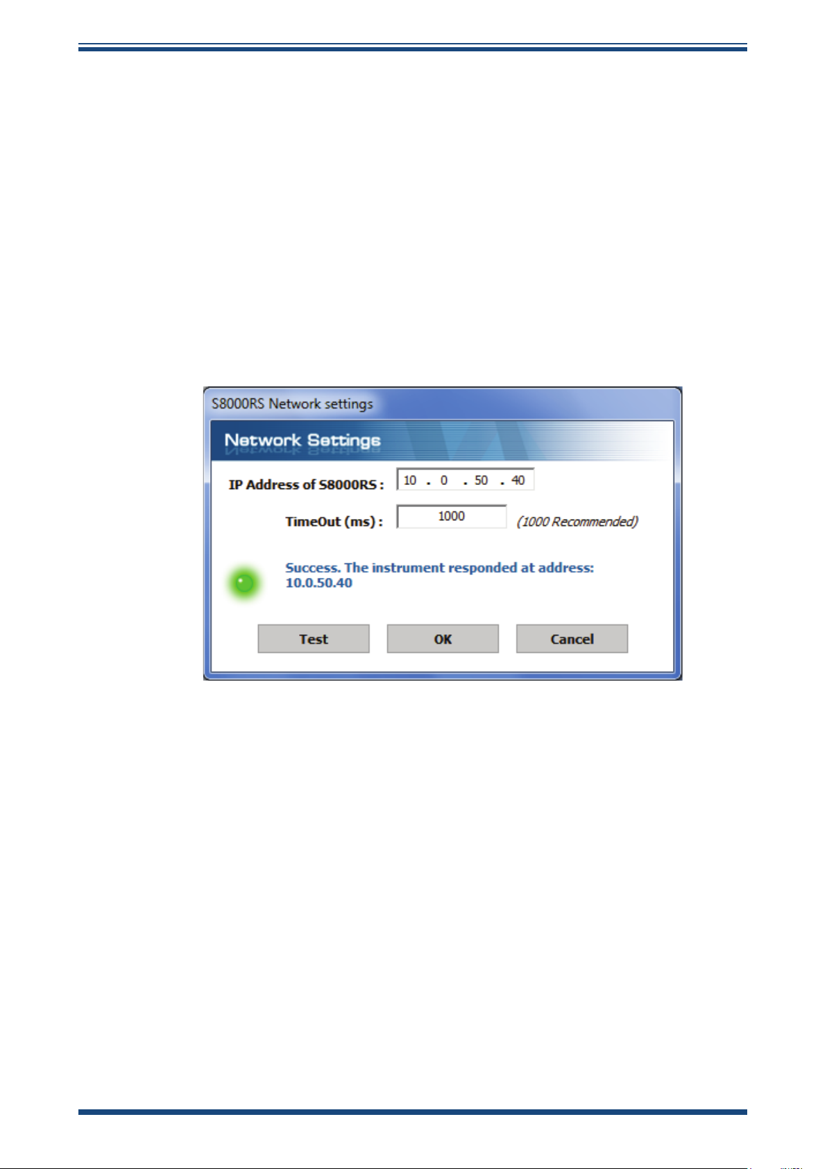
APPLICATION SOFTWARE
4.2.2 Ethernet Communication
1. Configure the network settings of the instrument. Refer to Section
3.2.13.
2. Connect the S8000 RS to the network using the supplied Ethernet
cable.
3. Launch the application software and choose the Network Connection
option.
4. Click the TCP Settings button to enter the IP address of the
instrument.
5. Click the Test button. If communication with the instrument is
successful then proceed to the next screen by clicking the OK
button, otherwise check network settings and try again.
S8000 RS User’s Manual S8000 RS User’s Manual
Figure 30
Network Settings Screen
40 97315 Issue 9, April 2019
Page 49

4.3 Data Acquisition or Edit Variables Mode
Once communication has been established, the Options Screen is displayed.
APPLICATION SOFTWARE
Figure 31
Options Screen
Michell Instruments 41
Page 50

APPLICATION SOFTWARE
4.3.1 Data Acquisition
This mode of operation allows all measured instrument parameters to be graphed and
logged in real time.
S8000 RS User’s Manual S8000 RS User’s Manual
Figure 32
Data Acquisition Control Toolbar
Data Acquisition Screen
Name Description
Run
Pause Pause data acquisition
Stop Stop data acquisition
Plot and log interval Time in seconds between graph and log file updates
Log filename
DCC
Maxcool
Standby
Begin data acquisition and logging
A filename must be first be selected to enable data logging
Path and filename of the log file
Click the small folder icon next to this text box to create a new
log file
Initiate a DCC cycle
Refer to Section 3.4.3 for detailed information on the DCC function
Toggle between Maxcool and Measure mode
Refer to Section 3.4.4 for detailed information on the Maxcool
function
Toggles between Standby and Measure mode
Refer to Section 3.4.8 for detailed information on the Standby
function
Table 15
Data Acquisition Control Description
42 97315 Issue 9, April 2019
Page 51

APPLICATION SOFTWARE
Instrument readings and status
This area displays all measured instrument parameters and shows the status of the
Fault, Process and Sensor Cooler Alarm.
Graph Controls
Name Description
Plot Automatically advances the graph as new data is acquired
Dragging the mouse on the graph scrolls along the time axis
Scroll Time
Zoom Time
Scroll Y
Zoom Y
Zoom Box Zooms in on both axes in the user selected area
Show time/Y
Options Displays the chart options window
Copy Copies the chart to the clipboard as a bitmap file
Drag to the left to scroll forwards
Drag to the right to scroll backwards
Dragging the mouse on the graph changes the scale of the time axis
Drag to the left to increase the scale size
Drag to the right to decrease the scale size
Dragging the mouse on the graph scrolls along the Y axis
Drag down to scroll up
Drag up to scroll down
Dragging the mouse on the graph changes the scale of the Y axis
Drag up to increase the scale size
Drag down to decrease the scale size
Select a parameter from the legend on the right hand side of the graph
Dragging the mouse along the graph will move the vertical cursor
along the time axis
The Y value for the selected parameter at the position of the cursor
will be displayed above the graph
Table 16
Graph
Plots the parameters selected by the user in the chart options window.
Status Bar
Graph Control Description
Name Description
Acquisition state
Number of
readings
Next reading
countdown
Log file Full path of the log file (if specified)
Indicates whether data acquisition is running, paused or stopped, with
the messages RUNNING, PAUSED or IDLE
Number of readings taken since starting the current acquisition session
Countdown timer (in seconds), which indicates when the next reading
will be taken
Table 17
Status Bar Description
Michell Instruments 43
Page 52

APPLICATION SOFTWARE
4.3.2 Variable Edit
The variable edit mode allows the instrument configuration to be changed through the
application software. On launch, it will automatically read and display the current values
of each of the instrument variables.
Note: The variables are not periodically updated on-screen. To obtain up-todate values, click the Read button.
Editing variables
To edit a variable, first click on it to highlight it.
If the variable has a fixed list of options, a drop-down arrow will appear in the righthand column. Choose a new value from the drop-down list provided.
If the variable does not have a fixed list of options, type the new value into the righthand column text input area.
S8000 RS User’s Manual S8000 RS User’s Manual
NOTE: The variable background colour will turn pink to indicate it has been
changed on-screen and is pending upload to the instrument.
Click the Write button to upload changed values to the instrument.
NOTE: Variable values and formatting are checked by the application software
before they are uploaded to the instrument.
A message box will report any errors found.
Once a modified value has been written to the instrument, the background colour will
return to white.
44 97315 Issue 9, April 2019
Page 53

APPLICATION SOFTWARE
Figure 33
Variables Editor Screen
Michell Instruments 45
Page 54

MAINTENANCE
!
DANGER
Electric
Shock Risk
5 MAINTENANCE
There are few user-serviceable parts on the S8000 RS. These include removal and
replacement of the AC power supply fuse and cleaning the sensor mirror.
Safety
S8000 RS User’s Manual S8000 RS User’s Manual
This equipment operates from power supply voltages that
can be lethal and at pressures (depending upon application)
that could cause injury.
Ensure that any test installation meets the standards
described in Section 2.3 of this manual.
Under NO circumstances should the instrument case be
removed or the air vents covered or in any way restricted.
Maintenance and repair, other than that described in this
section, must only be carried out by trained personnel and
the instrument should be returned to the manufacturer for
this purpose.
5.1 Fuse Replacement
If the instrument fails to operate after it has been connected to an AC power supply (85
to 264 V AC, 47/63 Hz) and switched on, proceed as follows:
1. If the power supply cable is fitted with a fused plug, switch off the
power supply and remove the plug. Check and, if necessary, replace
the fuse. If, after fitting a new fuse and switching the power supply
on, the instrument still fails to operate, proceed as follows.
Figure 34
Fuse Replacement
2. Switch the instrument’s ON/OFF switch to OFF, isolate the external
power supply and remove the IEC power connector from the
instrument’s power socket.
3. Locate the fuse carrier and pull it out of the connector housing. A
small screwdriver inserted under the lip may be useful in order to
lever it out.
46 97315 Issue 9, April 2019
Page 55

MAINTENANCE
4. Replace the fuse cartridge. NOTE: It is essential that a fuse of the
correct type and rating is fitted to the instrument (fuse - 3.15A,
Anti-Surge, Glass, 20mm x 5mm).
5. Fit a new fuse cartridge into the fuse carrier and push the fuse
carrier back into the power connector housing.
6. Replace the IEC power connector into the power socket, switch on
the external power supply and switch on the instrument. Check that
the instrument is now operational. If the fuse blows immediately on
switch-on either contact the manufacturer or their service agent.
DO NOT ATTEMPT ANY FURTHER SERVICING PROCEDURES
Michell Instruments 47
Page 56

MAINTENANCE
!
5.2 Sensor Mirror Cleaning
Before disassembling the sensor it is important to
Failure to follow this warning may result in operator injury
Throughout the life of the instrument, periodic cleaning of the mirror surface and optics
window may be required. The frequency of this depends upon operating conditions
and the potential in the application for contaminants to be deposited on the mirror.
Sensor cleaning is mandatory if the instrument indicates an optics fault. The cleaning
procedure is as follows:
S8000 RS User’s Manual S8000 RS User’s Manual
Warning
de-pressurize the sensor head.
or damage to the instrument.
2
3
Figure 35
1. Switch off the instrument and unscrew the large stainless steel
sensor cover (1) on the front of the instrument.
2. Carefully pull the optics block (2) out to reveal the mirror (3).
Clean the mirror surface and optics window with a cotton bud/
QTip soaked in distilled water. If the sensor has been exposed to
oil based contamination then use one of the following solvents:
methanol, ethanol, or isopropyl alcohol. To avoid damage to the
mirror surface, do not press too firmly on the cotton bud/Q-Tip
when cleaning. Allow the cleaning solvent to fully evaporate.
Sensor Mirror Cleaning
1
3. If alcohol has been used to clean the mirror then always follow by
cleaning with distilled water.
4. Replace the optics block, taking care to align the gold contacts on
the block with the gold contacts on the instrument.
5. Replace the large stainless steel cover, screwing it in firmly but
taking care not to overtighten it.
48 97315 Issue 9, April 2019
Page 57

6 GOOD MEASUREMENT PRACTICE
6.1 Sampling Hints
Ensuring reliable and accurate moisture measurements requires the correct sampling
techniques, and a basic understanding of how water vapour behaves. This section aims
to explain the common mistakes and how to avoid them.
Sampling Materials – Permeation and Diffusion
All materials are permeable to water vapour since water molecules are extremely
small compared to the structure of solids, even including the crystalline structure of
metals. The graph below demonstrates this effect by showing the increase in dew point
temperature seen when passing very dry gas through tubing of different materials,
where the exterior of the tubing is in the ambient environment.
MAINTENANCE
Figure 36
What this demonstrates is the dramatic effect that different tubing materials have on
the humidity levels of a gas passed through them. Many materials contain moisture
as part of their structure and when these are used as tubing for a dry gas the gas
will absorb some of the moisture. Always avoid using organic materials (e.g. rubber),
materials containing salts and anything which has small pores which can easily trap
moisture (e.g. nylon).
As well as trapping moisture, porous sampling materials will also allow moisture vapour
to ingress into the sample line from outside. This effect is called diffusion and occurs
when the partial water vapour pressure exerted on the outside of a sample tube is
higher than on the inside. Remember that water molecules are very small so in this
case the term ‘porous’ applies to materials that would be considered impermeable in
an everyday sense – such as polyethylene or PTFE. Stainless steel and other metals
can be considered as practically impermeable and it is surface finish of pipework that
becomes the dominant factor. Electropolished stainless steel gives the best results over
the shortest time period.
Take into consideration the gas you are measuring, and then choose materials appropriate
to the results you need. The effects of diffusion or moisture trapped in materials are
more significant when measuring very dry gases than when measuring a sample with a
high level of humidity.
Material permeability comparison
Michell Instruments 49
Page 58

GOOD MEASUREMENT PRACTICE
Temperature and Pressure effects
As the temperature or pressure of the environment fluctuates, water molecules are
adsorbed and desorbed from the internal surfaces of the sample tubing, causing small
fluctuations in the measured dew point.
S8000 RS User’s Manual S8000 RS User’s Manual
Adsorption
solid to the surface of a material, creating a film. The rate of adsorption is increased at
higher pressures and lower temperatures.
Desorption
constant environmental conditions, an adsorbed substance will remain on a surface
almost indefinitely. However, as the temperature rises, so does the likelihood of
desorption occurring.
Ensuring the temperature of the sampling components is kept at consistent levels is
important to prevent temperature fluctuation (i.e. through diurnal changes) continually
varying the rates of adsorption and desorption. This effect will manifest through a
measured value which increases during the day (as desorption peaks), then decreasing
at night as more moisture is adsorbed into the sampling equipment.
is the adhesion of atoms, ions, or molecules from a gas, liquid, or dissolved
is the release of a substance from or through the surface of a material. In
Dew Point > T
Dew Point < T
If temperatures drop below the sample dew point, water may condense in sample
tubing and affect the accuracy of measurements.
Maintaining the temperature of the sample system tubing above the dew point of the
sample is vital to prevent condensation. Any condensation invalidates the sampling
process as it reduces the water vapour content of the gas being measured. Condensed
liquid can also alter the humidity elsewhere by dripping or running to other locations
where it may re-evaporate.
Although ambient pressure does not change drastically in a single location, the gas
sample pressure does need to be kept constant to avoid inconsistencies introduced
by adsorption or desorption. The integrity of all connections is also an important
consideration, especially when sampling low dew points at an elevated pressure. If
a small leak occurs in a high-pressure line, gas will leak out, however, vortices at the
leak point and a negative vapour pressure differential will also allow water vapour to
contaminate the flow.
50 97315 Issue 9, April 2019
Page 59

GOOD MEASUREMENT PRACTICE
Theoretically flow rate has no direct effect on the measured moisture content, but
in practice it can have unanticipated effects on response speed and accuracy. An
inadequate flow rate may:
• Accentuate adsorption and desorption effects on the gas passing through
the sampling system.
• Allow pockets of wet gas to remain undisturbed in a complex sampling
system, which will then gradually be released into the sample flow.
• Increase the chance of contamination from back diffusion. Ambient air
that is wetter than the sample can flow from the exhaust back into the
system. A longer exhaust tube can help alleviate this problem.
• Slow the response of the sensor to changes in moisture content.
An excessively high flow rate can:
• Introduce back pressure, causing slower response times and unpredictable
changes in dew point
• Result in a reduction in depression capabilities in chilled mirror instruments
by having a cooling effect on the mirror. This is most apparent with gases
that have a high thermal conductivity such as hydrogen and helium.
System design for fastest response times
The more complicated the sample system, the more areas there are for trapped moisture
to hide. The key pitfalls to look out for here are the length of the sample tubing and
dead volumes.
The sample point should always be as close as possible to the critical measurement
point to obtain a truly representative measurement. The length of the sample line to the
sensor or instrument should be as short as possible. Interconnection points and valves
trap moisture, so using the simplest sampling arrangement possible will reduce the time
it takes for the sample system to dry out when purged with dry gas.
Over a long tubing run, water will inevitably migrate into any line, and the effects of
adsorption and desorption will become more apparent.
Dead volumes (areas which are not in a direct flow path) in sample lines, hold onto
water molecules which are slowly released into the passing gas. This results in increased
purge and response times, and wetter than expected readings. Hygroscopic materials
in filters, valves (e.g. rubber from pressure regulators) or any other parts of the system
can also trap moisture. Plan your sampling system to ensure that the sample tap point
and the measurement point are as close as possible to avoid long runs of tubing and
dead volumes.
Filtration
All trace moisture measurement instruments and sensors are by their nature sensitive
devices. Many processes contain dust, dirt or liquid droplets. Particulate filters are
used for removing dirt, rust, scale and any other solids that may be in a sample stream.
For protection against liquids, a coalescing or membrane filter should be used. The
membrane provides protection from liquid droplets and can even stop flow to the
analyser completely when a large slug of liquid is encountered, saving the sensor from
potentially irreparable damage.
Michell Instruments 51
Page 60
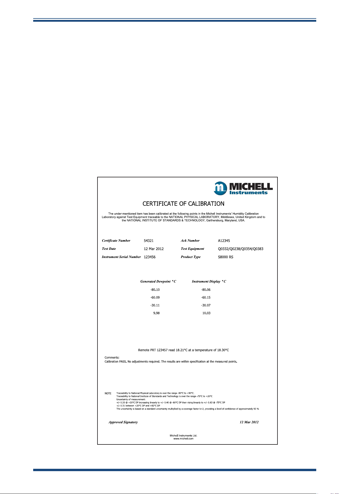
GOOD MEASUREMENT PRACTICE
7 CALIBRATION
7.1 Traceability
The calibration of this instrument is traceable to national standards. For this reason
the instrument can only be calibrated in an accredited e.g. NIST or UKAS accredited,
standards laboratory.
If these facilities do not exist, the instrument must be returned to the manufacturer,
Michell Instruments, or one of their approved agents (see www.michell.com for contact
details).
The DCC function can be disabled for calibration purposes (refer to Section 3.4.3).
A calibration certificate bearing a four point calibration is issued with each instrument.
If required, an option is available to add further specific calibration points. Contact
Michell Instruments for further information (www.michell.com).
S8000 RS User’s Manual S8000 RS User’s Manual
Figure 37
Typical Calibration Certificate
52 97315 Issue 9, April 2019
Page 61

Appendix A
CALIBRATION
Technical Specifications
Michell Instruments 53
Page 62

APPENDIX A
Appendix A Technical Specifications
Dew-Point Sensor Performance
Measurement Technology Chilled Mirror
Measurement Range
Measurement Accuracy* ±0.1°C (±0.18°F)
Reproducibility ±0.05°C (±0.09°F)
Mirror Gold plated copper
Temperature Measurement 4 wire Pt100, 1/10 DIN class B
Sample Flow Rate 500 to 1000 ml/min (1 to 2.1 scfh)
Sample Gas Pressure 1 MPa (10 barg / 145 psig) max
Remote PRT
Temperature Measurement 4 wire Pt100, 1/10 DIN class B
Measurement Accuracy ±0.1°C (±0.18°F)
Cable Length 2m (6.6ft) (250m (820ft) max)
Flow Sensor
Measurement Range 0 to 1000 ml/min (0 to 2.1 scfh)
RS80: -80 to +20°Cdp (-112 to +68°Fdp)
RS90: -90 to +20°Cdp (-130 to +68°Fdp)
S8000 RS User’s Manual S8000 RS User’s Manual
Optional Integrated Pressure Sensor
Measurement Range 0 to 1.6 MPa (0 to 16 bara / 0 to 232 psia)
Measurement Accuracy 0.25% Full Scale
Measurement Units barg, psig, kPa, MPa
Monitor
Resolution User selectable to 0.001, depending on parameter
Moisture: °Cdp or °Fdp, % RH, g/m3, g/kg, ppmV, ppmW (SF6)
Measurement Units
Outputs
HMI 5.7” LCD with touchscreen, white on blue graphics
Data Logging
Environmental Conditions +5 to +30°C (+41 to +86°F) max 80% RH
Power Supply 85 to 264 V AC, 47/63 Hz
Power Consumption 250 VA
Temperature: °C or °F
Pressure: barg, psig, kPa, MPa
Analog: Three channels, user selectable 4-20 mA, 0-20 mA or 0-1 V
Digital: USB and Modbus TCP (over Ethernet)
Alarm: Two volt free changeover contacts, one process alarm, one fault
alarm; 1 A @ 30 V DC
SD Card (512 Mb supplied) and USB interface. Supports SD Card (FAT-32) - 32
Gb max. that allows 24 million logs or 560 days, logging at 2 second intervals
Mechanical Specification
Dimensions 188.9 x 440 x 479.3mm (7.358 x 17.323 x 18.870") (h x w x d)
Weight 22.4kg (49.38lbs)
Sample Gas Circuit 316 Stainless steel
Sample Gas Connections
Optional Integrated
Sample Pump
Inlet: 1/4" VCR (MALE)
Outlet: 1/4" Swagelok (MALE)
Flow rate:
1.4l/min maximum
Sample gas connections:
1/4” Swagelok (MALE) with bypass loop
General
Calibration
* Measurement accuracy means maximum deviation between instrument under test and corrected
5-point in-house calibration, national standards traceable as standard
UKAS accredited calibrations optional – please consult factory
54 97315 Issue 9, April 2019
Page 63

APPENDIX A
186.9 mm
7.358 ins
36.6 mm
1.4 ins
479.3 mm
18.870 ins
46.0 mm
1.811 ins
178.5 mm
7.028 ins
440.0 mm
17.323 ins
177.0 mm
6.969 ins
144.5 mm
5.689 ins
36.6 mm
1.4 ins
479.3 mm
18.870 ins
reference. To this must be added the uncertainties associated with the calibration system and the
environmental conditions during testing or subsequent use.
20
10
0
-10
-20
-30
-40
-50
Temperature (ºC)
-60
-70
-80
-90
-100
-110
Sensor Cooler Maximum Depression
Figure 38
Operational Range
Michell Instruments 55
Figure 39
S8000 RS Dimensions
Page 64

APPENDIX B
S8000 RS User’s Manual S8000 RS User’s Manual
Appendix B
Default Set-Up Parameters
56 97315 Issue 9, April 2019
Page 65

Appendix B Default Set-Up Parameters
Sub Menu Parameter Value Unit
APPENDIX B
MAIN SCREEN
DCC
LOGGING
DISPLAY
OUTPUTS
Top Readout Parameter
Mid Readout Parameter
Bottom Readout Parameter
Display Hold
Period/Duration
Setpoint
Interval/Measurement Time
Output Hold/Hold Duration
Interval 5 seconds
Resolution
Primary Unit/Temperature Unit
Pressure Unit
Stability Time
FAST
PRT Mode
Language
Brightness/Display Contrast
Output 1 Parameter
Output 2 Parameter
Output 3 Parameter
Output 1 Type
Output 2 Type
Output 3 Type
Output 1 Min
Output 1 Max
Output 2 Min
Output 2 Max
Output 3 Min
Output 3 Max
Dewpoint
ppm
V
Flow
0 (Off)
4
20
4
20
3
ºC
bara
1
On
Internal
English
100
Dewpoint
ppm
V
Flow
4-20 mA
4-20 mA
4-20 mA
-80
20
0
3000
0
1000
minutes
minutes
ºC
hours
minutes
decimal places
minute
%
ºC
ºC
ppm
V
ppm
V
ml/min
ml/min
ALARM
COOLER
Parameter
Setpoint
Mode
Setpoint
Dewpoint
0 ºC
Automatic
N/A
Table 18
Default Set-Up Parameters
Michell Instruments 57
Page 66

APPENDIX C
S8000 RS User’s Manual S8000 RS User’s Manual
Appendix C
Modbus Holding
Register Map
58 97315 Issue 9, April 2019
Page 67

APPENDIX C
Appendix C Modbus Holding Register Map
All the data values relating to the S8000 RS are stored in holding registers. Each of these registers
is two bytes (16-bits wide). Some of these registers contain instrument specific values e.g. its own
unique system address, IP address values, etc. Others registers hold specific real time data e.g.
measured dew-point and temperature.
Each Modbus message has a two part address code, one for the low byte (bits 0 through 7) and one
for the high byte (bits 8 through 15). The facility exists for multiple registers, specified by a high and
low byte contained in the query message, to be addressed and read by the same message.
The table below describes the instruments' registers with their respective address locations, together
with their relevant register configurations and register map definitions. Note: Hexadecimal (Hex)
addresses marked with an asterisk denote instrument specific parameters stored in the
instrument’s flash memory.
The register maps below the table define the data allocated to each bit/byte for each register type.
Address
Dec
Address
Hex
Function Read/
Write
Default
Value
Register
Confi-
Register Map
Definition
guration
0 0000* Instrument Address R/W 0001H H INSTID
1 0001 Dew point Value – Hi Word R N HUMIDITY_HI
2 0002
3 0003
4 0004
5 0005 RH R A RH
6 0006 Pressure Value R J PRESSURE
7 0007 PpmV – Hi Word R N PPMV_HI
8 0008 PpmV – Lo Word R N PPMV_LO
9 0009 PpmW(sf6) – Hi Word R N PPMWSF_HI
10 000A PpmW(sf6) – Lo Word R N PPMWSF_LO
11 000B g/m3 - Hi Word R N GM3_HI
12 000C g/m3 - Lo Word R N GM3_LO
13 000D g/kg – Hi Word R N GKG_HI
14 000E g/kg – Lo Word R N GKG_LO
15 000F Flow Value R H FLOW_RATE
16 0010 Mirror Condition R J MIRROR_COND
17 0011 Heat Pump Drive R H HP_DRIVE
18 0012 Status R D STATUS
19 0013*
20 0014*
21 0015 Phase Time Hours R L PHASE_TIME_HRS
22 0016
23 0017* Film thickness setting R/W A FILM_THICKNESS
Dew point Value – Lo
Word
Ambient Temperature – Hi
Word
Ambient Temperature – Lo
Word
DCC period + Hold Time
Duration minutes
DCC Interval Hours +
Minutes
Phase Time Minutes +
Phase Time Seconds
R N HUMIDITY_LO
R N AMBTEMP_HI
R N AMBTEMP_LO
R/W K DCC_HOLD_TIME
R/W K MEASURE_TIME
R K
PHASE_TIME_
MIN_SEC
Michell Instruments 59
Page 68

APPENDIX C
S8000 RS User’s Manual S8000 RS User’s Manual
24 0018 Live film thickness value R A
25 0019*
26 001A*
27 001B*
28 001C*
29 001D*
30 001E*
31 001F*
32 0020*
33 0021* Logging Interval R/W H LOG_INTERVAL
34 0022* Units/ Command R/W E UNITSCOMMAND
35 0023*
36 0024* Emitter Drive R/W H EMITTERDRIVE
37 0025 Stability Time R/W H STABILITY_TIME
38 0026
39 0027
40 0028
41 0029* Display Setting 1 R/W F
42 002A* Display Setting 2 R/W F
43 002B N/A
44 002C N/A
45 002D N/A
46 002E Filename DDMM or MMDD R L FILENAME_DDMM
47 002F Filename HHMM R L FILENAME_HHMM
48 0030* Firmware Version Number R A FIRM_VER
49 0031 N/A
50 0032 N/A
51 0033* N/A
52 0034*
53 0035* Process Alarm Set Point R/W M
181
182
Analog 1 output maximum
value
Analog 1 output minimum
value
Analog 2 output maximum
value
Analog 2 output minimum
value
Analog 3 output maximum
value
Analog 3 output minimum
value
Analog output
configuration 1
Analog output
configuration 2
Mirror Temp Set-Point
during DCC
RTC Year(val1) + Month
(val2)
RTC Date (val1) +
Hours(val2)
RTC Mins(val1) + Secs
(val2)
Process Alarm
Configuration / Display
Brightness.
IP Address – octets 1 and
2
IP Address – octets 3 and
4
R/W M MAX_MA1
R/W M MIN_MA1
R/W M MAX_MA2
R/W M MIN_MA2
R/W M MAX_MA3
R/W M MIN_MA3
R/W B OP_SELECTION1
R/W B OP_SELECTION2
R/W A
R/W K YEARMONTH
R/W K DATEHRS
R/W K MINSSECS
R/W P
R/W n/a T IPADDR1
R/W n/a T IPADDR2
LIVE_FILM_
THICKNESS
MIRROR_TEMP
_SETP
DISPLAY_
SETTING1
DISPLAY_
SETTING2
ALARMCONFIG_
DISPCONT
PROCESSALARM_
SP_HI
60 97315 Issue 9, April 2019
Page 69

APPENDIX C
Sign bit = 1 for –ve values (signed int)
7FFF = 327.67
8000 = -327.68
The value in bits (15 to 0) + 1 is divided by 100 to give 0.01 resolution
for dew point and temperature values
Value
183
184
185
186
187 Ethernet Status R/W 0x0000 U ETHSTATUS
Default Gateway– octets 1
and 2
Default Gateway – octets
3 and 4
Subnet Mask – Hi Word octets 1 and 2
Subnet Mask – Lo Word octets 3 and 4
Table 19
R/W n/a T DGADDR1
R/W n/a T DGADDR2
R/W n/a T NMASK1
R/W n/a T NMASK2
Register Map
Register Configuration A
15 14 13 12 11 10 9 8 7 6 5 4 3 2 1 0
r r r r r r r r r r r r r r r r
Register Configuration B - Analog Output Configuration 1
15 14 13 12 11 10 9 8 7 6 5 4 3 2 1 0
Analog O/P 2 Analog O/P 1
r/w r/w r/w r/w r/w r/w r/w r/w r/w r/w r/w r/w r/w r/w r/w r/w
DP = 00000000
temp = 00000001
Ppm(V) = 00000010
Ppm(W) sf6 = 00000011
g/kg = 00000100
3
g/m
= 00000101
pressure = 00000110
flow = 00000111
rh = 00001000
temp difference = 00001001
DP = 00000000
temp = 00000001
Ppm(V) = 00000010
Ppm(W) sf6 = 00000011
g/kg = 00000100
g/m3 = 00000101
pressure = 00000110
flow = 00000111
rh = 00001000
temp difference = 00001001
Michell Instruments 61
Page 70

APPENDIX C
Register Configuration B - Analog Output Configuration 2
15 14 13 12 11 10 9 8 7 6 5 4 3 2 1 0
r/w r/w r/w r/w r/w r/w r/w r/w r/w r/w r/w r/w r/w r/w r/w r/w
Register Configuration D - Status Word
Analog O/P 3
00 = 0- 20mA
01= 4-20mA
10 = 0-1V
Analog O/P 2
00 = 0- 20mA
01= 4-20mA
10 = 0-1V
Analog O/P 1
00 = 0- 20mA
S8000 RS User’s Manual S8000 RS User’s Manual
Analog O/P 3
DP = 00000000
temp = 00000001
Ppm(V) = 00000010
Ppm(W) sf6 = 00000011
g/kg = 00000100
g/m3 = 00000101
pressure = 00000110
flow = 00000111
rh = 00001000
01= 4-20mA
10 = 0-1V
temp difference = 00001001
15 14 13 12 11 10 9 8 7 6 5 4 3 2 1 0
r/w r/w r/w r/w r/w r r r r/w r/w r r r r r r
1= Optics Reset
1= Display hold
1= Max Cool Initiate
1= DCC initiate
(toggle ON/OFF)
1= Start Logging
0= Stop Logging
1= FAST
(Frost Assurance)
1= Fault Alarm
1= Humidity Alarm
1= External PRT
1= Initiate Standby
In-control = 00
Heating = 01
Cooling = 10
Register Configuration E - Units
15 14 13 12 11 10 9 8 7 6 5 4 3 2 1 0
r/w r/w r/w r/w r/w r/w r/w r/w r/w r/w r/w r/w r/w r/w r/w r/w
Language
ENGLISH
GERMAN
SPANISH
FRENCH
ITALIAN
PORTUG
USA
RUSSIAN
CHINESE
0
1
2
3
4
5
6
13
15
Measurement = 0000
DCC = 0001
Data Hold = 0010
Max Cool = 0100
Standby = 1000
Reset defaults
1 = FAST Enable
1 DP = 00H
2 DP = 01H
3 DP = 10H
N/A
SENSOR COOLER AUTO/MANUAL
M 1, A 0
Psig = 00H
Bara = 01H
Kpa = 10H
Mpag = 11H
Moisture Content Calculation
0 = dry basis; 1 = wet basis
%rh calculation over water/ice
0= over water
N/A
°C = 0
62 97315 Issue 9, April 2019
°F = 1
Page 71

APPENDIX C
Register Configuration F - Display Setting A & B
A
15 14 13 12 11 10 9 8 7 6 5 4 3 2 1 0
Display 2 Display 1
r/w r/w r/w r/w r/w r/w r/w r/w r/w r/w r/w r/w r/w r/w r/w r/w
DP = 00000000
temp = 00000001
Ppm(V) = 00000010
Ppm(W) sf6 = 00000011
g/kg = 00000100
3
g/m
= 00000101
pressure = 00000110
flow = 00000111
rh = 00001000
temp difference = 00001001
DP = 00000000
temp = 00000001
Ppm(V) = 00000010
Ppm(W) sf6 = 00000011
g/kg = 00000100
3
g/m
= 00000101
pressure = 00000110
flow = 00000111
rh = 00001000
temp difference = 00001001
B
15 14 13 12 11 10 9 8 7 6 5 4 3 2 1 0
Main Value to Log Display 3
r/w r/w r/w r/w r/w r/w r/w r/w r/w r/w r/w r/w r/w r/w r/w r/w
DP, Temp, Press and Flow are logged
by default
DP = 00000000
temp = 00000001
Ppm(V) = 00000010
Ppm(V) = 00000010
Ppm(W) sf6 =00000011
g/kg = 00000100
g/m3 = 00000101
rh = 00001000
temp difference = 00001001
Ppm(W) sf6 = 00000011
g/kg = 00000100
g/m3 = 00000101
pressure = 00000110
flow = 00000111
rh = 00001000
temp difference = 00001001
Register Configuration H
15 14 13 12 11 10 9 8 7 6 5 4 3 2 1 0
r/w r/w r/w r/w r/w r/w r/w r/w r/w r/w r/w r/w r/w r/w r/w r/w
Unsigned integer. Range = 0 to 65535
Michell Instruments 63
Page 72

APPENDIX C
Val 1 Val 2
Val 1 Val 2
Sign bit = 1 for –ve values (signed int)
7FFF = 32767
8000 = -32768
Value
Register Configuration J
15 14 13 12 11 10 9 8 7 6 5 4 3 2 1 0
r r r r r r r r r r r r r r r r
S8000 RS User’s Manual S8000 RS User’s Manual
Value
Sign bit = 1 for –ve values (signed int)
7FFF = 3276.7
8000 = -3276.8
The value in bits (15 to 0) + 1 is divided by 10 to give 0.1 resolution
for dew point and temperature values.
Register Configuration K
15 14 13 12 11 10 9 8 7 6 5 4 3 2 1 0
r/w r/w r/w r/w r/w r/w r/w r/w r/w r/w r/w r/w r/w r/w r/w r/w
Val 1 & 2 are in BCD, therefore 10H = 10, 58H = 58 and 09H = 9 etc., so as a result A
to F are not valid values
Register Configuration L
15 14 13 12 11 10 9 8 7 6 5 4 3 2 1 0
r/w r/w r/w r/w r/w r/w r/w r/w r/w r/w r/w r/w r/w r/w r/w r/w
Values in HEX i.e. 17th March = 11H for Val1 and 03H for Val2
Register Configuration M - signed int
15 14 13 12 11 10 9 8 7 6 5 4 3 2 1 0
r r r r r r r r r r r r r r r r
64 97315 Issue 9, April 2019
Page 73

APPENDIX C
Register Configuration N - Floating Point Representation.
The humidity values for sensors 1 & 2 are represented in IEEE-754 single precision
floating point format, in order to cater for the wide range in the value of ppm(v). This
format is 'Big Ended' which means that the Hi byte is at a lower address in memory
than the Lo byte, and is represented as such in the register memory map. The IEEE-754
format is shown below:
Bit 31
Sign Bit
0 = +
1 = -
Examples of floating point to HEX are shown below:
Example 1 +10.3
Sign bit = 0
Exponent = 3, therefore exponent field = 127 + 3 = 130, and bits 30 to 23 =10000010
The mantissa = 1.2875 which in binary representation = 1.01001001 1001 1001 1001
101
Adjusting the mantissa for the exponent moves the decimal point to the right if positive
and to the left if negative
As the exponent is = 3 then the mantissa becomes = 1010.0100 1100 1100 1100 1101,
therefore:-
Bits 30 to 23
Exponent Field
Has a +127 bias value
Bits 22 to 0
Mantissa
Decimal representation of binary
Where 1.0 ≤ value < 2.0
1010 = (1x23 + (0x22) + (1x21) + (0x20) = 10 and
0100 1100 1100 1100 1101 = (0x2-1) +(1x2-2) +....+ (1x2-20) = 0.3
Therefore the word value = 0100 0001 0010 0100 1100 1100 1100 1101 = 4124CCCD
Consequently for sensor 1, register 0001 = 4124 and register 0002 = CCCD
Example 2 - 0.0000045
Sign bit = 1
Exponent = -18, therefore exponent field = 127 + (-18) = 109, and bits 30 to 23 =
01101101
The mantissa = 1.179648 which in binary representation = 1.00101101111111010110101
i.e. (1x2-18) +(1x2-21) + (1x2-23) etc = 0.0000045
Therefore the word value = 1011 0110 1001 0110 1111 1110 1011 0101 = B696FEB5
Consequently for sensor 1 register 0001 = B696 and register 0002 = FEB5
Michell Instruments 65
Page 74

APPENDIX D
S8000 RS User’s Manual S8000 RS User’s Manual
Appendix D
Quality, Recycling
& Warranty
Information
66 97315 Issue 9, April 2019
Page 75

APPENDIX D
Appendix D Quality, Recycling & Warranty Information
Michell Instruments is dedicated to complying to all relevant legislation and directives. Full information
can be found on our website at:
www.michell.com/compliance
This page contains information on the following directives:
• ATEX Directive
• Calibration Facilities
• Conflict Minerals
• FCC Statement
• Manufacturing Quality
• Modern Slavery Statement
• Pressure Equipment Directive
• REACH
• RoHS2
• WEEE2
• Recycling Policy
• Warranty and Returns
This information is also available in PDF format.
Michell Instruments 67
Page 76

APPENDIX E
S8000 RS User’s Manual S8000 RS User’s Manual
Appendix E
Analyzer Return Document
&
Decontamination Declaration
68 97315 Issue 9, April 2019
Page 77

APPENDIX E
Appendix E Analyzer Return Document & Decontamination Declaration
Decontamination Certicate
IMPORTANT NOTE: Please complete this form prior to this instrument, or any components, leaving your
site and being returned to us, or, where applicable, prior to any work being carried out by a Michell
engineer at your site.
Instrument Serial Number
Warranty Repair? YES NO Original PO #
Company Name Contact Name
Address
Telephone # E-mail address
Reason for Return /Description of Fault:
Has this equipment been exposed (internally or externally) to any of the following?
Please circle (YES/NO) as applicable and provide details below
Biohazards YES NO
Biological agents YES NO
Hazardous chemicals YES NO
Radioactive substances YES NO
Other hazards YES NO
Please provide details of any hazardous materials used with this equipment as indicated above (use continuation sheet
if necessary)
Your method of cleaning/decontamination
Has the equipment been cleaned and decontaminated? YES NOT NECESSARY
Michell Instruments will not accept instruments that have been exposed to toxins, radio-activity or bio-hazardous
materials. For most applications involving solvents, acidic, basic, ammable or toxic gases a simple purge with dry
gas (dew point <-30°C) over 24 hours should be sufcient to decontaminate the unit prior to return.
Work will not be carried out on any unit that does not have a completed decontamination declaration.
Decontamination Declaration
I declare that the information above is true and complete to the best of my knowledge, and it is safe for Michell
personnel to service or repair the returned instrument.
Name (Print) Position
Signature Date
F0121, Issue 2, December 2011
Michell Instruments 69
Page 78

http://www.michell.com
 Loading...