

Page 1
S8000
Chilled Mirror Hygrometer
User’s Manual
97488 Issue 4
August 2018
Page 2

Please fi ll out the form(s) below for each instrument that has been purchased.
Use this information when contacting Michell Instruments for service purposes.
Instrument
Code
Serial Number
Invoice Date
Location of Instrument
Tag No
Instrument
Code
Serial Number
Invoice Date
Location of Instrument
Tag No
Instrument
Code
Serial Number
Invoice Date
Location of Instrument
Tag No
Page 3
S8000
For Michell Instruments' contact information please go to
www.michell.com
© 2018 Michell Instruments
This document is the property of Michell Instruments Ltd. and may not be copied or
otherwise reproduced, communicated in any way to third parties, nor stored in any Data
Processing System without the express written authorization of Michell Instruments Ltd.
Page 4

S8000 User’s Manual
Contents
Safety ................................................................................................................................ix
Electrical Safety ...........................................................................................................ix
Pressure Safety ............................................................................................................ix
Toxic Materials .............................................................................................................ix
Repair and Maintenance ...............................................................................................ix
Calibration ...................................................................................................................ix
Safety Conformity ........................................................................................................ix
Abbreviations ...................................................................................................................... x
Warnings ............................................................................................................................ x
1 INTRODUCTION ................................................................................................1
1.1 Operating Principle ............................................................................................. 2
2 INSTALLATION ..................................................................................................3
2.1 Safety ................................................................................................................ 3
2.2 Unpacking the Instrument ................................................................................... 3
2.3 Operating Requirements ..................................................................................... 5
2.3.1 Environmental Requirements ......................................................................... 5
2.3.2 Electrical Requirements ................................................................................. 5
2.4 Exterior Layout ................................................................................................... 5
2.5 Rear Panel Connections (All Versions) .................................................................. 8
2.5.1 Power Supply Input ....................................................................................... 9
2.5.2 Analog Output Connections .......................................................................... 10
2.5.3 Alarm Output Connections ........................................................................... 11
2.5.4 Remote PRT Probe (Optional) ..................................................................... 13
2.5.5 4-Wire PRT Output (Optional) ...................................................................... 14
2.5.6 USB Communications Port Connector ............................................................ 14
2.5.7 Ethernet Port (Optional) .............................................................................. 15
2.5.8 RS232/485 Port (Optional) ........................................................................... 15
2.5.9 Connection of Gas Supplies .......................................................................... 17
2.6 Internal Sample Pump (Optional) ....................................................................... 19
2.7 Conversion of S8000 to Rack Mount .................................................................. 20
3 OPERATION ....................................................................................................21
3.1 General Operational Information ........................................................................ 21
3.2 Instrument Display ........................................................................................... 22
3.2.1 Main Screen ................................................................................................ 23
3.2.2 Customizable Readouts................................................................................ 24
3.2.3 Operational Status Display ........................................................................... 24
3.2.4 Setup Menu Screen ..................................................................................... 25
3.2.5 Menu Structure .......................................................................................... 27
3.2.6 DCC ........................................................................................................... 28
3.2.7 LOGGING ................................................................................................... 29
3.2.8 OUTPUTS ................................................................................................... 31
3.2.9 ALARM ....................................................................................................... 31
3.2.10 DISPLAY .................................................................................................... 32
3.2.11 CLOCK ....................................................................................................... 33
3.2.12 ABOUT (Network Settings) ........................................................................... 33
3.3 Operational Functions ....................................................................................... 34
3.3.1 Operating Cycle .......................................................................................... 34
3.4 Operating Guide ............................................................................................... 35
3.4.1 DCC - Dynamic Contamination Control .......................................................... 35
3.4.2 MAXCOOL Function ..................................................................................... 36
3.4.3 Pressure Compensation ............................................................................... 36
iv 97488 Issue 4, August 2018
Page 5

S8000 User’s Manual
3.4.4 Data Logging .............................................................................................. 36
3.4.5 Frost Assurance System Technology (FAST) .................................................. 37
3.4.6 STANDBY Mode........................................................................................... 37
4 APPLICATION SOFTWARE ................................................................................38
4.1 Installation ....................................................................................................... 38
4.2 Establishing Communications ............................................................................ 38
4.2.1 USB Communication .................................................................................... 39
4.2.2 RS232/485 Communication .......................................................................... 40
4.2.3 Ethernet Communication ............................................................................. 40
4.3 Data Acquisition or Edit Variables Mode .............................................................. 41
4.3.1 Data Acquisition .......................................................................................... 42
4.3.2 Variable Edit ............................................................................................... 44
5 MAINTENANCE ................................................................................................46
5.1 Safety .............................................................................................................. 46
5.2 Fuse Replacement ........................................................................................... 47
5.3 Sensor Mirror Cleaning ...................................................................................... 48
5.3.1 Releasing optics window ............................................................................. 49
5.3.2 Fitting the Microscope (Optional) .................................................................. 50
6 GOOD MEASUREMENT PRACTICE .....................................................................51
6.1 Sampling Hints ................................................................................................. 52
7 CALIBRATION ..................................................................................................55
7.1 Traceability ...................................................................................................... 55
8 PREPARATION FOR SHIPPING ..........................................................................56
Michell Instruments v
Page 6

S8000 User’s Manual
Tables
Table 1 Front Panel Controls and Indicators ..............................................................6
Table 2 Rear Panel Controls and Indicators ...............................................................8
Table 3 Main Screen Description ............................................................................. 23
Table 4 Operational Status Display ........................................................................24
Table 5 DCC Parameters ........................................................................................28
Table 6 Logging Parameters ................................................................................... 29
Table 7 SD Card Status Indicators .......................................................................... 30
Table 8 Outputs Parameters ................................................................................... 31
Table 9 Alarm Parameters ...................................................................................... 31
Table 10 Display Parameters .................................................................................... 32
Table 11 Clock Parameters .......................................................................................33
Table 12 Network Parameters .................................................................................. 33
Table 13 Data Acquisition Control Description ...........................................................42
Table 14 Graph Control Description .......................................................................... 43
Table 15 Status Bar Description ...............................................................................43
Table 16 Modbus Holding Register Map ....................................................................69
Table 17 Register Confi guration A ............................................................................ 70
Table 18 Register Confi guration B1 ...........................................................................70
Table 19 Register Confi guration B2 ...........................................................................70
Table 20 Register Confi guration D Status Word ......................................................... 71
Table 21 Register Confi guration E Units ....................................................................71
Table 22 Register Confi guration F Display Setting A ...................................................71
Table 23 Register Confi guration F Display Setting B ................................................... 72
Table 24 Register Confi guration H ............................................................................72
Table 25 Register Confi guration J .............................................................................72
Table 26 Register Confi guration K ............................................................................ 72
Table 27 Register Confi guration L .............................................................................73
Table 28 Register Confi guration M ............................................................................ 73
Table 29 Register Confi guration N ............................................................................73
Table 30 Register Confi guration P ............................................................................. 74
vi 97488 Issue 4, August 2018
Page 7

S8000 User’s Manual
Figures
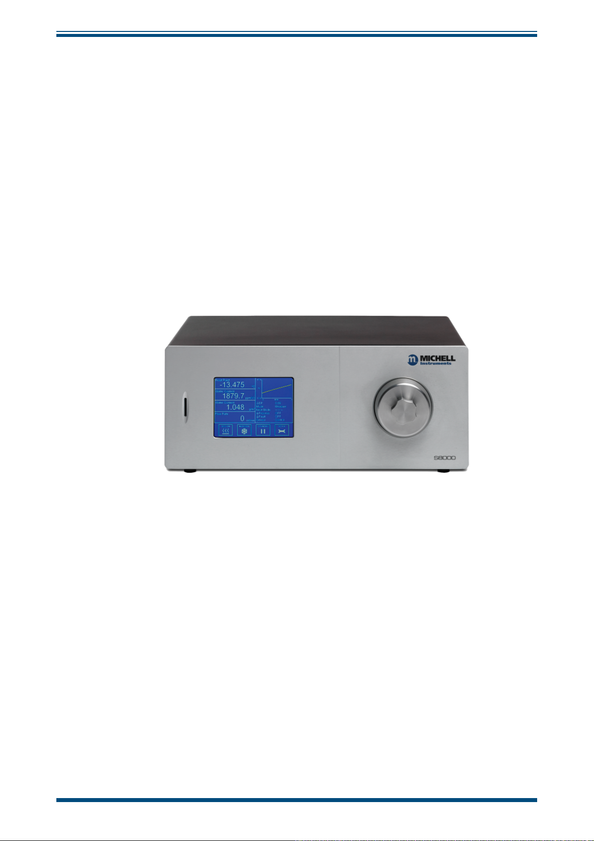
Figure 1 S8000 ........................................................................................................1
Figure 2 Operating Principle .....................................................................................2
Figure 3 S8000 Packing ............................................................................................3
Figure 4 Front Panel ................................................................................................6
Figure 5 Rear Panel .................................................................................................7
Figure 6 Power Supply Input ....................................................................................9
Figure 7 Analog Output Connectors ........................................................................10
Figure 8 Alarm Output Connectors ..........................................................................12
Figure 9 Remote PRT Connection ............................................................................13
Figure 10 Internal PRT Output (Optional) ..................................................................14
Figure 11 USB Port Connection .................................................................................14
Figure 12 Ethernet Port (Optional) ............................................................................15
Figure 13 RS232/485 Port (Optional) ........................................................................15
Figure 14 Gas Connections .......................................................................................17
Figure 15 Gas Connections when Pump is Fitted ........................................................ 19
Figure 16 Rack Fixing Method ..................................................................................20
Figure 17 Initialising Overlay Screen .........................................................................22
Figure 18 Main Screen .............................................................................................22
Figure 19 Main Screen Layout ..................................................................................23
Figure 20 Setup Menu Screen ..................................................................................25
Figure 21 Virtual Keyboard ...................................................................................... 26
Figure 22 Menu Structure ........................................................................................27
Figure 23 DCC Screen .............................................................................................. 28
Figure 24 Logging Screen ........................................................................................29
Figure 25 Outputs Screen ........................................................................................31
Figure 26 Alarm Screen ...........................................................................................31
Figure 27 Display Screen .........................................................................................32
Figure 28 Clock Screen ............................................................................................33
Figure 29 Network Settings Screen ...........................................................................33
Figure 30 Typical Operating Cycle .............................................................................34
Figure 31 Communications Setup Screen ..................................................................38
Figure 32 Windows Device Manager Screen ..............................................................39
Figure 33 Network Settings Screen ...........................................................................40
Figure 34 Options Screen .........................................................................................41
Figure 35 Data Acquisition Screen ............................................................................42
Figure 36 Variables Editor Screen .............................................................................45
Figure 37 Power Supply Fuse Replacement ...............................................................47
Figure 38 Sensor Mirror Cleaning ..............................................................................48
Figure 39 Releasing Optics Window ..........................................................................49
Figure 40 Fitting the Microscope ...............................................................................50
Figure 41 Typical Calibration Certifi cate ..................................................................... 55
Figure 42 Instrument Packing Details ........................................................................56
Figure 43 Select Format ...........................................................................................62
Figure 44 Set Format Properties ...............................................................................62
Figure 45 Format Disc .............................................................................................62
Figure 46 Modbus Connection ..................................................................................67
Michell Instruments vii
Page 8

S8000 User’s Manual
Appendices
Appendix A Technical Specifi cations .............................................................................. 58
A.1 Dimensions ................................................................................. 60
Appendix B Formatting SD cards ................................................................................. 62
Appendix C Calculations ..............................................................................................64
C.1 Water Content ............................................................................. 64
C.2 Temperature - Dew Point ...........................................................64
C.3 °C to °F Calculation .................................................................... 64
C.4 % RH Calculation ........................................................................64
C.5 Conversion of bara to psia and kPa .............................................. 65
Appendix D Modbus RTU Communications ....................................................................67
D.1 Introduction ............................................................................... 67
D.2 Basic Modbus Operation .............................................................. 67
D.3 Modbus RTU Connections and Protocol .......................................... 68
D.4 Register Map .............................................................................. 68
Appendix E Default Values ........................................................................................... 76
Appendix F Quality, Recycling & Warranty Information ................................................... 78
Appendix G Return Document & Decontamination Declaration ........................................ 80
viii 97488 Issue 4, August 2018
Page 9
S8000 User’s Manual
!
Safety
The manufacturer has designed this equipment to be safe when operated using the procedures
detailed in this manual. The user must not use this equipment for any other purpose than that
stated. Do not apply values greater than the maximum value stated.
This manual contains operating and safety instructions, which must be followed to ensure the safe
operation and to maintain the equipment in a safe condition. The safety instructions are either
warnings or cautions issued to protect the user and the equipment from injury or damage. Use
qualifi ed personnel and good engineering practice for all procedures in this manual.
Electrical Safety
The instrument is designed to be completely safe when used with options and accessories supplied
by the manufacturer for use with the instrument. The input power supply voltage limits are 85 to
264 V AC, 47/63 Hz. Refer to Appendix A - Technical Specifi cations.
Pressure Safety
Before pressurizing, the user must ensure through appropriate
protective measures that the system or the device will not be over-
pressurized. When working with the instrument and pressurized
gases safety glasses should be worn.
DO NOT permit pressures greater than the safe working pressure to be applied to the instrument.
The specifi ed maximum safe working pressure is 1 barg (14.5 psig) for the low pressure version,
or 20 barg (290 psig) for the high pressure version. This instrument is not designed to accept gas
pressures higher than the specifi ed maximum working pressure.
Application of gas pressures higher than the specifi ed maximum will result in potential damage
and may render the instrument unsafe and in a condition of incorrect functionality. Only personnel
trained in the safe handling of high pressure gases should be allowed to operate this instrument.
Refer to Appendix A - Technical Specifi cations in this manual.
Toxic Materials
The use of hazardous materials in the construction of this instrument has been minimized. During
normal operation, it is not possible for the user to come into contact with any hazardous substance,
which might be employed in the construction of the instrument. Care should, however, be exercised
during maintenance and the disposal of certain parts.
Repair and Maintenance
The instrument must be maintained either by the manufacturer or an accredited service agent. Refer
to www.michell.com for details of Michell instruments' worldwide offi ces contact information.
Calibration
The recommended calibration interval for the S8000 is one year, unless otherwise specifi ed by Michell
Instruments Ltd. The instrument should be returned to the manufacturer, Michell Instruments, or one
of their accredited service agents for re-calibration (go to www.michell.com for contact information).
Safety Conformity
This product meets the essential protection requirements of the relevant EU directives. Refer to
Appendix A - Technical Specifi cations - for details.
Michell Instruments ix
Page 10

Abbreviations
!
DANGER
Electric
Shock Risk
The following abbreviations are used in this manual:
DCC Dynamic Contamination Correction
FAST Frost Assurance System Technology
MAXCOOL Maximum Sensor Cooling
AC alternating current
atm pressure unit (atmosphere)
barg pressure unit (=100 kP or 0.987 atm) gauge
bara pressure unit (absolute)
°C degrees Celsius
°F degrees Fahrenheit
COM common
dp dew point
EU European Union
g/Kg grams per kilogram
3
grams per cubic meter
g/m
HMI Human Machine Interface
Hz Hertz
IEC International Electrotechnical Commission
Nl/min normal liters per minute
lb pound
mA milliampere
max maximum
min minute(s)
mV millivolt(s)
N/C normally closed
N/O normally open
No number
parts per million (by volume)
ppm
V
ppmW parts per million (by weight)
PRT Platinum resistance thermometer (typically type Pt 100)
psig pound(s) per square inch (gauge)
psia pound(s) per square inch (absolute)
RH relative humidity
RTU Remote Terminal Unit
scfh standard cubic feet per hour
SD storage device card (memory card for storing datalog fi les)
temp temperature
USB Universal Serial Bus
V Volts
S8000 User’s Manual
Warnings
The following general warnings listed below are applicable to this instrument. They are
repeated in the text in the appropriate locations.
Where this hazard warning symbol appears in the following
sections, it is used to indicate areas where potentially
hazardous operations need to be carried out.
Where this symbol appears in the following sections it is
used to indicate areas of potential risk of electric shock.
x 97488 Issue 4, August 2018
Page 11
S8000 User’s Manual
1 INTRODUCTION
The S8000 is a high precision instrument used for the measurement of dew point in air
and other gases. Relative humidity, moisture content, and other calculated parameters
based on dew point, pressure and temperature of the sample gas can also be displayed.
The S8000 is capable of measuring dew points as low as -60°C (-76°F); it can measure
dew points up to (but not including) the point of condensation (maximum +40°C
(+104 °F)).
Two models of the S8000 instrument are available:
• Low Pressure (1 barg (14.5 psig) max)
• High Pressure (20 barg (290 psig) max)
INTRODUCTION
Figure 1
S8000
Michell Instruments 1
Page 12
INTRODUCTION
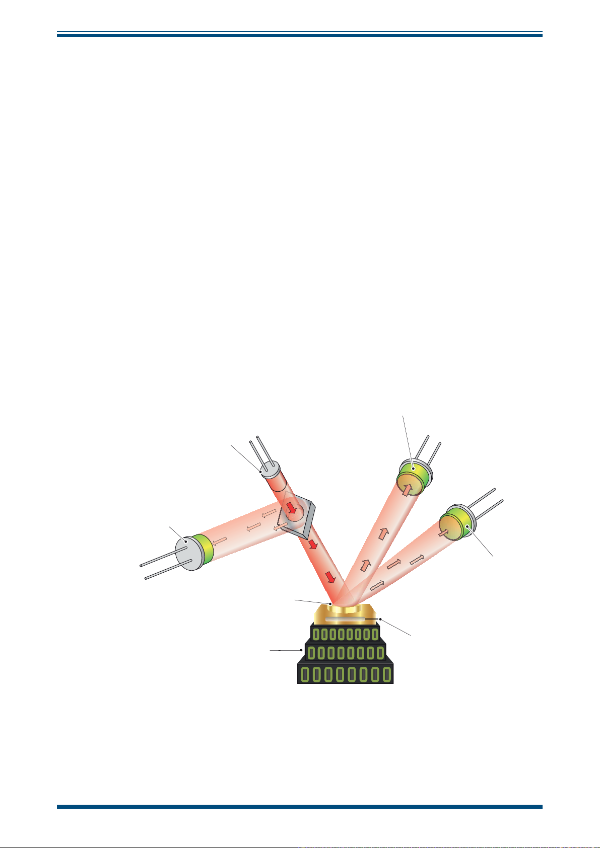
1.1 Operating Principle
The system operates on the chilled mirror principle, whereby a gas sample is passed
into the sensor housing and fl ows over the surface of the chilled mirror contained
within. At a temperature dependent upon the moisture content in the gas, and the
operating pressure, the moisture in the gas condenses out on the surface of the mirror.
An optical system is used to detect the point at which this occurs, and this information
is used to control the mirror temperature and maintain a constant thickness of the
condensation layer on the mirror surface.
A beam of light from an LED (1) is focused on the mirror surface (2) with a fi xed
intensity. As the mirror is cooled, less light is refl ected due to the scattering effect of
the condensate formed on the mirror surface. The levels of refl ected and scattered light
are measured by two photo-detectors (3 & 4) and compared against a third reference
detector (5) measuring the intensity of light from the LED.
The signals from this optics system are used to precisely control the drive to a solid
state thermoelectric cooler (TEC) (6), which heats or cools the mirror surface. The
mirror surface is then controlled in an equilibrium state whereby evaporation and
condensation are occurring at the same rate. In this condition, the temperature of the
mirror, measured by a platinum resistance thermometer (7), is equal to the dew-point
temperature of the gas.
S8000 User’s Manual
3
1
5
4
2
7
6
Figure 2
Operating Principle
2 97488 Issue 4, August 2018
Page 13
S8000 User’s Manual
!
2 INSTALLATION
2.1 Safety
It is essential that the installation of the electrical and gas
supplies to this instrument be undertaken by competent
2.2 Unpacking the Instrument
INSTALLATION
personnel.
1
23
4
5
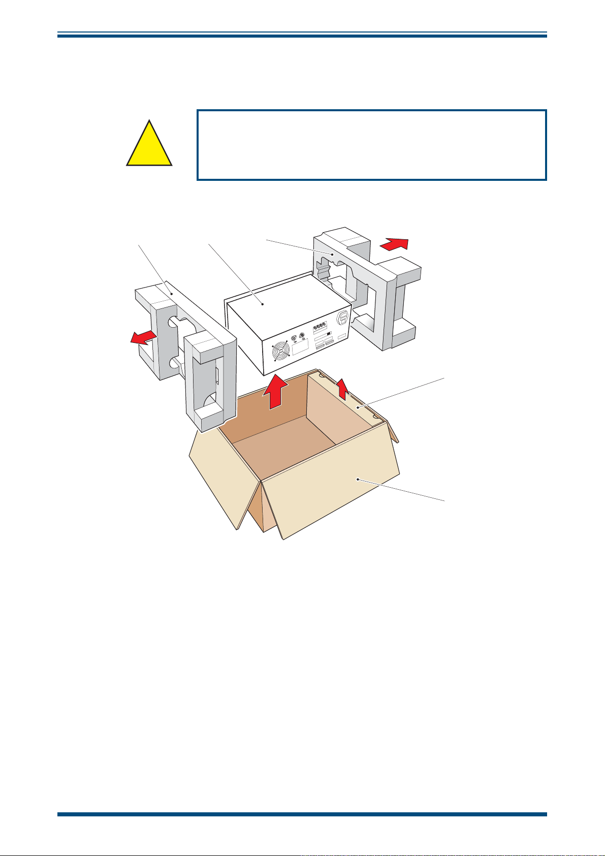
Figure 3
Open the box (5) and unpack carefully as follows (see
1. Remove the accessories box (4).
2. Lift out the instrument (2) together with its end packing pieces (1) and
(3).
3. Remove the end packing pieces (1) and (3) set the instrument down at
the site of installation.
4. Save all the packing materials for the purpose of returning the instrument
for re-calibration or any warranty claims.
S8000 Packing
Figure 3)
:
Michell Instruments 3
Page 14

INSTALLATION
S8000 User’s Manual
The accessories box should contain the following items
1. Traceable calibration certifi cate
2. User's manual
3. IEC power cable
4. SD memory storage card
5. Optics cleaning kit
6. Allen Key SMM
7. USB communications cable
8. Pt100 temperature probe (optional)
9. CAT5 ethernet cable (optional)
10. Microscope (optional)
If there are any shortages, please notify Michell Instruments immediately
(see www.michell.com for contact information).
:
4 97488 Issue 4, August 2018
Page 15
S8000 User’s Manual
!
2.3 Operating Requirements
2.3.1 Environmental Requirements
The S8000 instrument should either be placed on a fi rm and level surface in a laboratory
environment, or mounted into a standard 19" rack. Recommended ambient temperature
+20 to +25°C (+68 to +77°F) although the instrument will operate, within specifi cation,
at elevated ambient temperatures of up to +40°C (+104°F), providing the cooling
vents are kept clear and unrestricted. It is essential however that this upper
temperature limit (+40°C (+104°F)) is not exceeded.
A free fl ow of air around the instrument is required at all times.
The instrument is suitable for mounting in a standard 19" rack.
INSTALLATION
For rack mounted instruments, forced air cooling of the
rack should be considered if operating at high ambient
2.3.2 Electrical Requirements
All versions of the instrument require the following electrical supply:
• 85 to 264 V AC, 47/63 Hz, 100 VA max
• Alarm outputs for all instrument types comprise two sets of changeover
relay contacts, one set for a
INSTRUMENT FAULT. Both sets of contacts are rated at 24 V, 1 A. NOTE:
THIS RATING MUST NOT BE EXCEEDED.
2.4 Exterior Layout
temperatures.
PROCESS alarm and one set for an
The controls and indicators relating to the operator interface are located on the front
panel.
The external PRT connection, mains power IEC socket, analog output connector, remote
temperature probe connector, alarm relay connector, the USB socket, and the Ethernet
socket (optional) are located on the rear panel.
Figures 5 and 6
and vertical versions of the instrument. Tables 1 and 2 detail the controls and indicators
and the function key operations.
show the layout of these controls for both the rack mount/horizontal
Michell Instruments 5
Page 16
INSTALLATION
Front Panel
S8000 User’s Manual
11
13
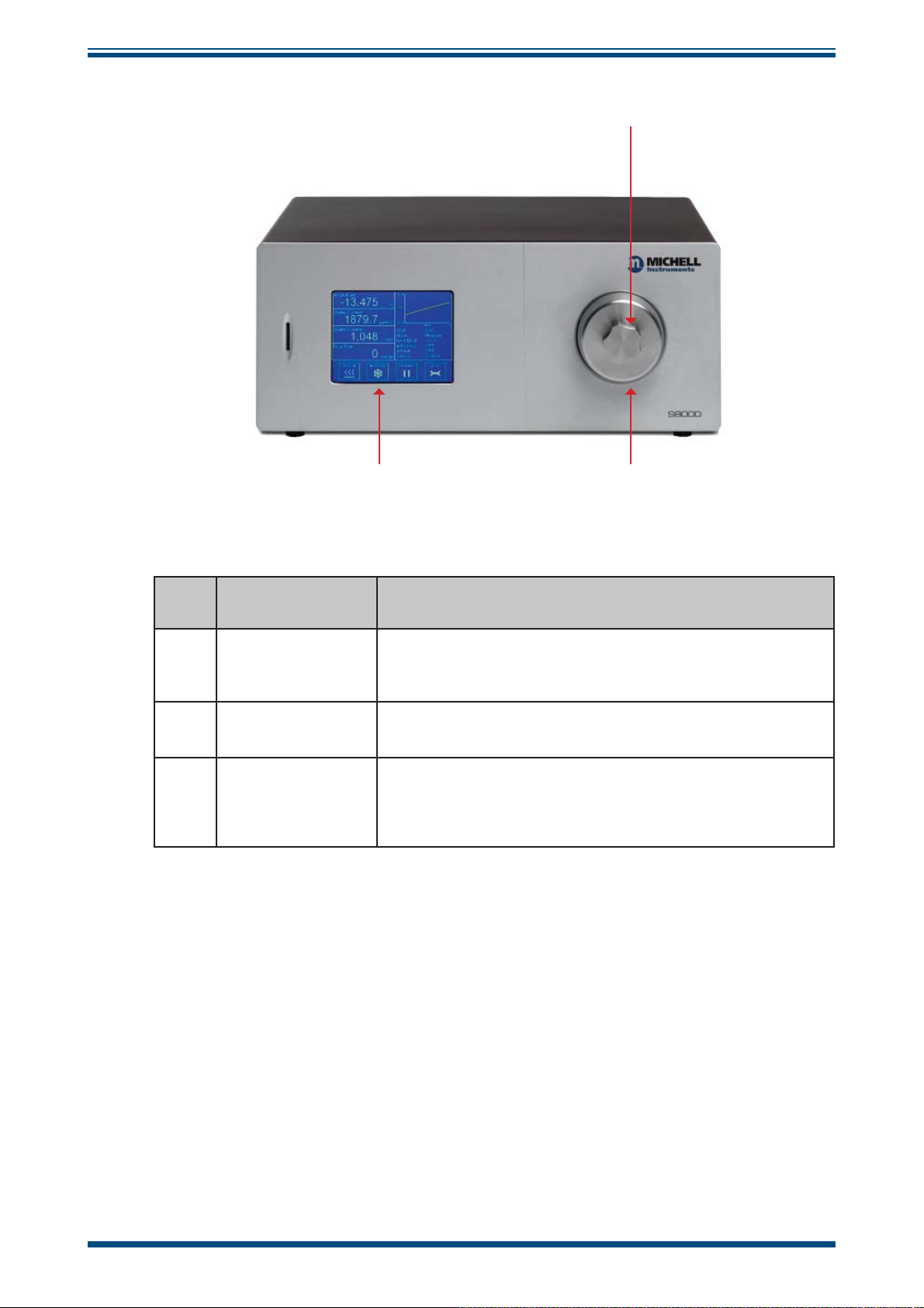
Figure 4
Item Name Description
Microscope
1
Blanking Plug
2 Sensor Housing
Touch Screen
3
Display
Table 1 Front Panel Controls and Indicators
Used to cover the microscope port when not in use. Also
to be used as a key to remove optics window (see Section
5.3).
Exterior housing of the sensor.
See Section 5.3 for information about the sensor head.
Displays measured values and enables the user to control
the operation of the instrument.
See Section 3.2 for information about the touch screen and
menu system.
Front Panel
12
6 97488 Issue 4, August 2018
Page 17
S8000 User’s Manual
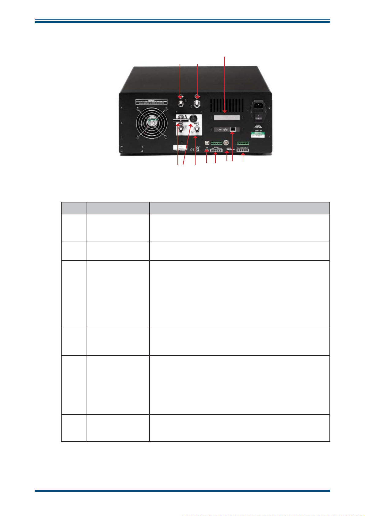
Rear Panel
INSTALLATION
7455
8 77 56
59 10512514513
Figure 5
Item Name Description
Usually slightly above atmospheric pressure in order to
4 Gas Input Port
maintain fl ow rate over the mirror, but can be up to a
maximum of 20 barg depending upon application.
Rear Panel
711
5 Gas Output Port Usually vented to atmosphere.
Three, 2-wire output channels, CH1, CH2 and CH3, each
of which may be confi gured to give either a 0-20 mA or a
4-20 mA current loop output or a 0 to 1 V voltage signal
Analog Output
6
Connector
Remote
7
Temperature
Probe (optional)
8 Alarms
USB
9
Communications
Port
representing any one of the measured or calculated output
parameters selected.
Spans for each signal output are separately confi gurable.
Refer to Section 2.5.2.
6-Pin Lemo socket for connection of remote Pt100
temperature probe.
Process and Fault alarm outputs. Each alarm has one set of
potential free, changeover, relay contacts, common (COM),
normally closed (N/C) and normally open (N/O).
The Process alarm can be confi gured to operate at a specifi ed
level on any of the measured or calculated parameters.
Refer to Section 2.5.3.
Used for connection to an external computer system for
running application software (optional).
Michell Instruments 7
Page 18
INSTALLATION
!
DANGER
Electric
Shock Risk
RJ45 Ethernet
10
11
Socket
(Optional)
4-wire PRT
bridge output
(Optional)
S8000 User’s Manual
Used for communication with the instrument over a network
connection.
See Section 4.2.3 for details on how to confi gure the
network settings.
See Section 4 for information on using and installing the
application software.
Banana sockets for external 4-wire measurement of the
internal PRT. Active only when PRT set to External from
Display options, and instrument is in the MEASURE phase.
In this mode the dew-point display is set to read zero, DCC
is set to OFF and manual DCC is also disabled.
12
13
14
Flow Control
Valve (Optional)
Pump Input Port
(Optional)
Pump Output
Port (Optional)
Table 2 Rear Panel Controls and Indicators
Used to regulate fl ow through the sensor when pump is in
use.
Can be linked to Gas Output port with supplied tubing for
operation with sample pump - NOT TO BE USED ABOVE
ATMOSPHERIC PRESSURE.
Vented to atmosphere when pump is in use.
2.5 Rear Panel Connections (All Versions)
These tasks should be undertaken only by competent
personnel.
All the connections to the rear panel are electrical
connections.
Exercise due caution, particularly when connecting to
external alarm circuits which could be at high potential.
Connections to the rear panel of the instrument are explained in the following sections.
8 97488 Issue 4, August 2018
Page 19
S8000 User’s Manual
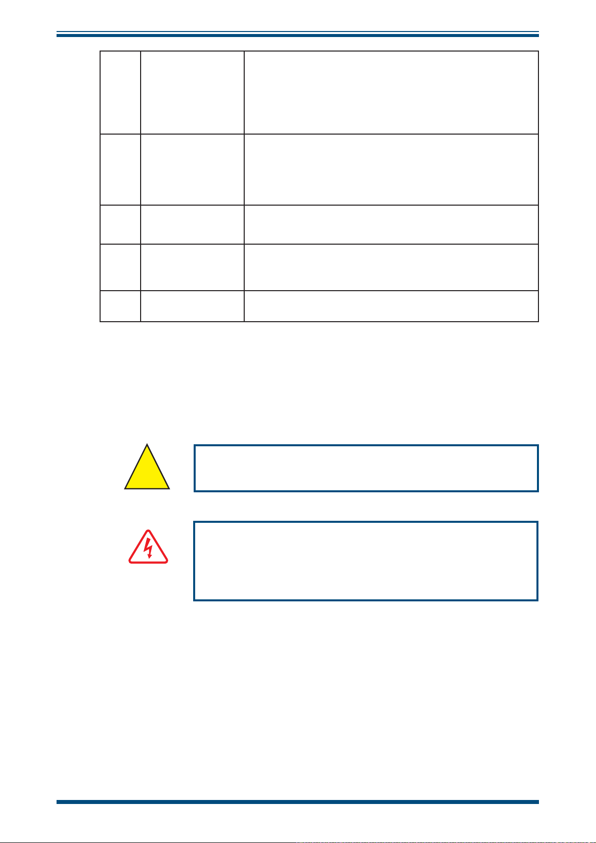
2.5.1 Power Supply Input
INSTALLATION
The AC power supply is a push fi t into the power input socket as shown in
method of connection is as follows:
11
Figure 7
13
2
1. Ensure that both ends of the power cable are potential free i.e. not
connected to an AC power supply.
2. Check that the
is switched to
ON/OFF switch (1) on the power supply connector
OFF.
. The
3. Push the IEC connector (3) fi rmly into the power input socket (2).
4. Connect the free end of the power cable to a suitable AC power
supply source (voltage range 85 to 264 V AC, 47/63 Hz) and switch
on the AC supply. The instrument may then be switched on, as
required, using the
ON/OFF switch.
Figure 6
Power Supply Input
Michell Instruments 9
Page 20
INSTALLATION
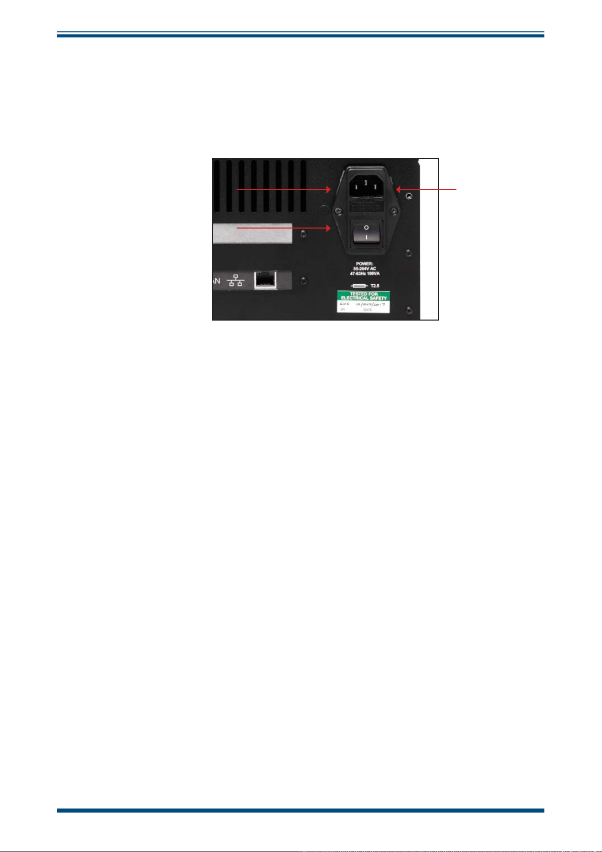
2.5.2 Analog Output Connections
The three analog outputs can be confi gured to represent any of the directly measured
or calculated output parameters. They are provided as 2-wire signals from a 6-way
connector located on the rear panel of the instrument
Each of these outputs can be set up as either a current loop signal (4-20 mA or 0-20
mA) or alternatively, as a 0-1 V voltage signal. The confi guration of these outputs, i.e.
parameter represented, output type (current loop or voltage) and upper/lower span
levels are set up via the
SETUP Menu Screen (refer to Section 3.2.4).
S8000 User’s Manual
.
These signals may be used to control external systems. During a
HOLD period following a DCC cycle, they are held at the level that they were at
the
immediately prior to the start of the cycle. When the dew-point measurement is stable,
or if the maximum
selected parameter throughout the measurement cycle.
The default settings of these analog outputs are:
HOLD period has expired, they are released and will track the
DCC cycle, and for
Channel 1: 4-20 mA, dew point, -60 to +20°C
Channel 2: 4-20 mA, ppm
, 0 to 3000
V
Channel 3: 4-20 mA, fl ow, 0 to 1000ml
NOTE: The analog outputs are only active during the
will, therefore, be off after switch-on and remain off until the system enters
MEASURE phase.
the
The three analog output ports connections are made via a single, 6-way, push fi t
connector block as shown in
common 0 V line. To differentiate between the outputs it is recommended that a black
lead be used for each of the COM (common) lines and a separate color for each of the
positive lines.
Figure 8
. All outputs are 2-wire signals referenced to a
MEASURE phase. They
Figure 7
Analog Output Connectors
10 97488 Issue 4, August 2018
Page 21

S8000 User’s Manual
For each output:
1. Remove the terminal block fi tted into the analog output socket.
INSTALLATION
2. Strip back the wire for the common (black) connection to the
exposing approximately 6mm (0.25"). Insert the wire into the
terminal way and screw into the block. Do not overtighten the screw.
3. Strip back the wire for the signal (e.g. red) connection to the
exposing approximately 6mm (0.25"). Insert the wire into the
terminal way and screw into the block. Do not overtighten the screw.
4. Repeat operations 1 and 2 for the other analog outputs, selecting a
different color for the
5. Locate the terminal block over the connector labelled
OUTPUTS and push the terminal block fi rmly into the connector.
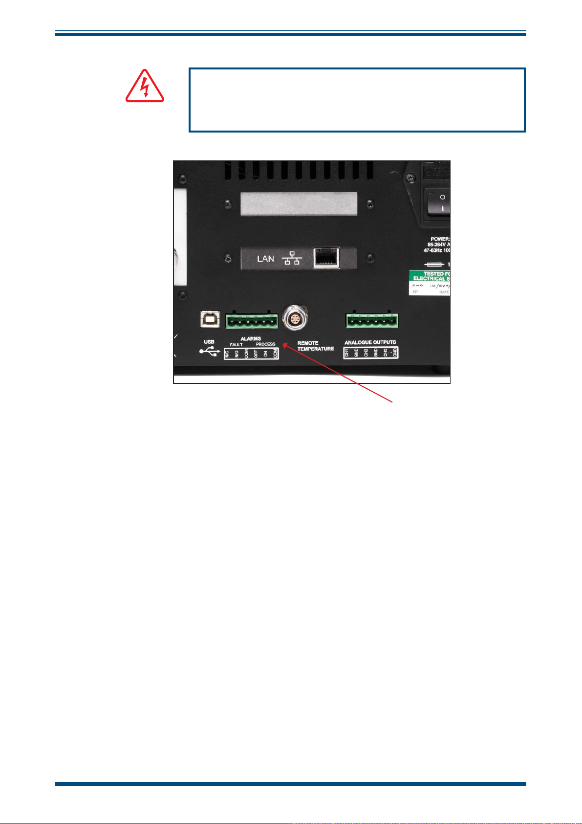
2.5.3 Alarm Output Connections
Two alarm outputs are provided from a terminal block (Item 9,
rear panel of the instrument as two pairs of potential free, change-over relay contacts.
These are designated as a
PROCESS alarm and a FAU LT alarm.
OP2 and OP3 outputs.
CH1 output,
OP1 output,
ANALOGUE
Figure 6),
COM1
OP1
located on the
Under the
represent any one of the measured or calculated parameters and set-up to operate when
a pre-set parameter threshold level is exceeded. By default, the
monitor the dew-point parameter.
The
of contamination of the chilled mirror. During normal operational conditions, this alarm
will be off. If the optics or the mirror contamination exceeds 100% of the fi lm thickness,
or if a fault exists on the Pt100, the alarm is triggered, and the relay contacts will
change state.
This fault is also reported to the status area of the display.
The two alarm output ports are connected to the instrument via a single 6-way, push-fi t
connector block as shown in
free, change-over relay contacts.
Each contact set is labelled
SETUP menu, (refer to Section 3.2.4), the PROCESS alarm can be confi gured to
PROCESS alarm is set to
FAU LT alarm is a non-confi gurable alarm which continuously monitors the degree
Figure 9
. Each output comprises a 3-wire set of potential
COM (common 0 V), N/O (normally open with respect to
COM) and N/C (normally closed with respect to COM).
To differentiate between the alarm output channels, it is recommended that a black lead
be used for each of the
N/C lines.
and
COM (common) lines and a separate color for each of the N/O
Michell Instruments 11
Page 22
INSTALLATION
DANGER
Electric
Shock Risk
S8000 User’s Manual
WARNING: Alarm leads MUST be potential free when wiring
to connector block.
Figure 8
For each output:
1. Strip back the wire for the common (black) connection to the
connector way for the
6mm (0.25") wire and clamp into the screw block
not overtighten the screw.
2. Strip back the wire for the
connector way for the
6mm (0.25") wire and clamp into the screw block N/O terminal way. Do
not overtighten the screw.
3. Strip back the wire for the
connector way for the
6mm (0.25") wire and clamp into the screw block
not overtighten the screw.
4. Repeat operations 1 to 3 for the
appropriate colored wires.
FAU LT alarm contact set, exposing approximately
FAU LT alarm contact set, exposing approximately
FAU LT alarm contact set, exposing approximately
Alarm Output Connectors
COM terminal way. Do
N/O (e.g. green) connection to the N/O
N/C (e.g. blue) connection to the N/C
N/C terminal way. Do
PROCESS alarm contact set, using
COM
5. Locate the terminal block over the connector labelled
the terminal block fi rmly into the connector.
ALARMS and push
12 97488 Issue 4, August 2018
Page 23

S8000 User’s Manual
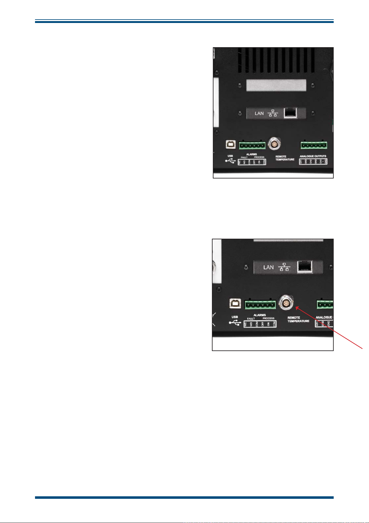
2.5.4 Remote PRT Probe (Optional)
1. Rotate the body of the PRT probe connector until it locates in the socket
labelled
2. Push the connector into the socket until it locks. Do not attempt to
force it into the socket. If it will not fi t in, rotate it until the key
locks and it pushes in easily.
3. To remove the connector, slide the connector’s body collar (1) back along
its axis, away from the instrument to release the lock and then gently pull
the connector body out of the socket. Do not attempt to pull it out
with the cable - make sure that the collar is fi rst released.
REMOTE TEMPERATURE (see
INSTALLATION
Figure 10).
Figure 9
Remote PRT Connection
Michell Instruments 13
Page 24
INSTALLATION
2.5.5 4-Wire PRT Output (Optional)
These four terminal binding posts (Item 1,
Figure 11),
external monitoring purposes.
Two pairs of lines are provided, two drive and
two sense lines. One black (low) and one red
(high) for the drive lines, and one black (low)
and one red (high) for the sense lines.
Connections to these terminal posts can be
made either via 4mm plugs pushed into the
ends of the terminal posts or, alternatively, as
shown, wires (5) connected round the posts
and clamped down by screw action.
are provided for calibration and
S8000 User’s Manual
To set-up the system for
Section 3.2.10.
2.5.6 USB Communications Port Connector
PRT output refer to
Figure 10
The instrument features a USB port for
communication with the Application
Software. The appropriate cable will be
supplied with the instrument.
1. Check the orientation of the connector
and gently push it into the socket
labelled
2. To remove the connector, pull it out of
the socket by holding the connector
body. Do not attempt to remove it from
the socket by pulling on the cable.
USB (see
Figure 12)
.
Internal PRT Output (Optional)
For more information on how to confi gure the Application Software go to Section 4.
Figure 11
USB Port Connection
14 97488 Issue 4, August 2018
Page 25
S8000 User’s Manual
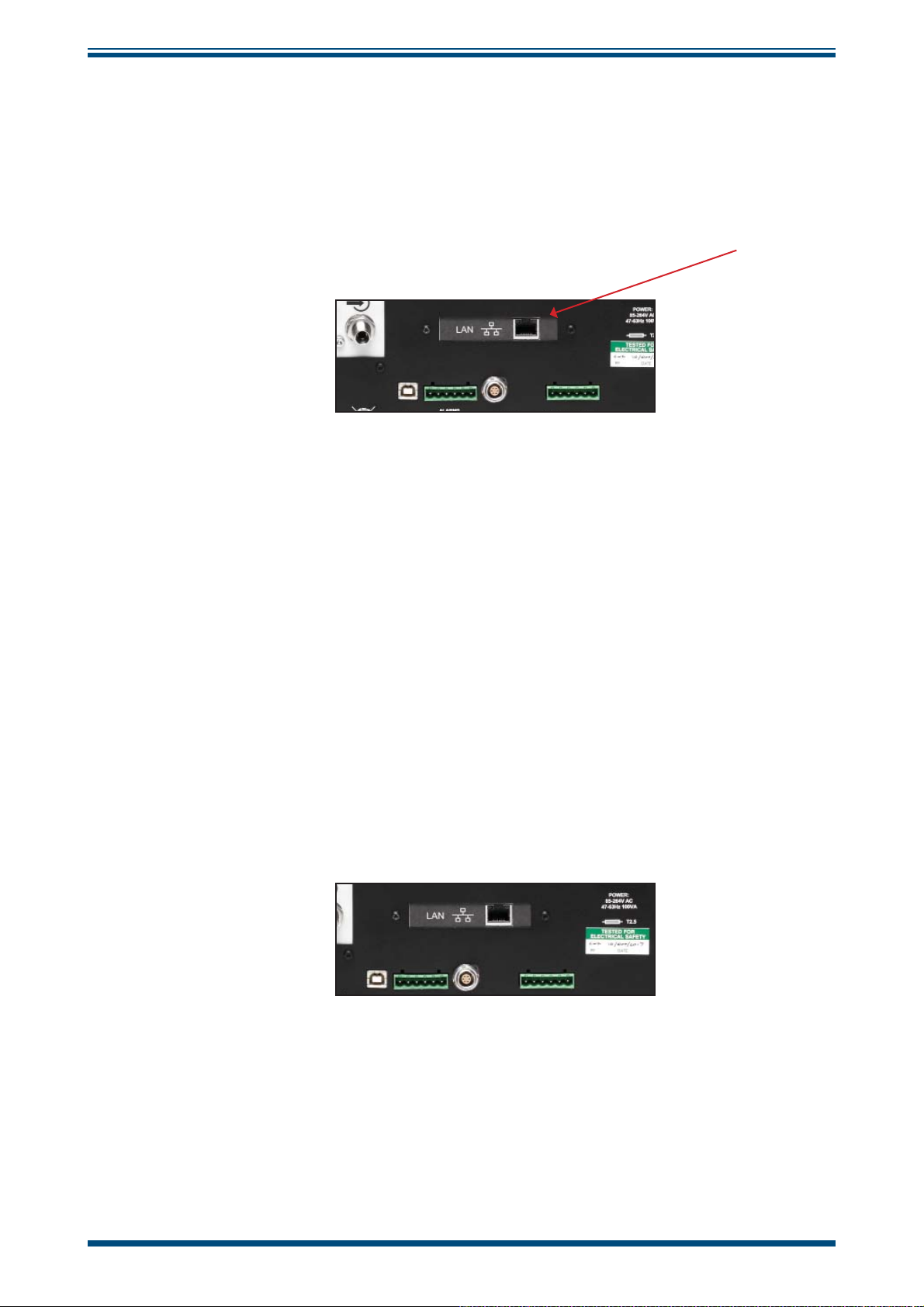
2.5.7 Ethernet Port (Optional)
The instrument features an optional RJ45 port for communication with the Application
Software.
1. Check the orientation of the connector and gently push it into the socket
labelled
LAN.
INSTALLATION
Figure 12
2. To remove the connector, depress the small locking tab on the top and
pull it out of the socket by holding the connector body.
For more information on how to confi gure the Application Software go to Section 4.
2.5.8 RS232/485 Port (Optional)
The instrument features an optional RS232/485 port for communication with the
application software. This is designed to be used with a standard 9-pin D-sub connector.
1. Check the orientation of the connector and gently push it into the socket
labelled
RS232 or RS485, and tighten the retaining screws.
Ethernet Port (Optional)
Figure 13
2. Loosen the retaining screws, and pull the connector out of the socket by
holding the connector body.
RS232/485 Port (Optional)
Michell Instruments 15
Page 26
INSTALLATION
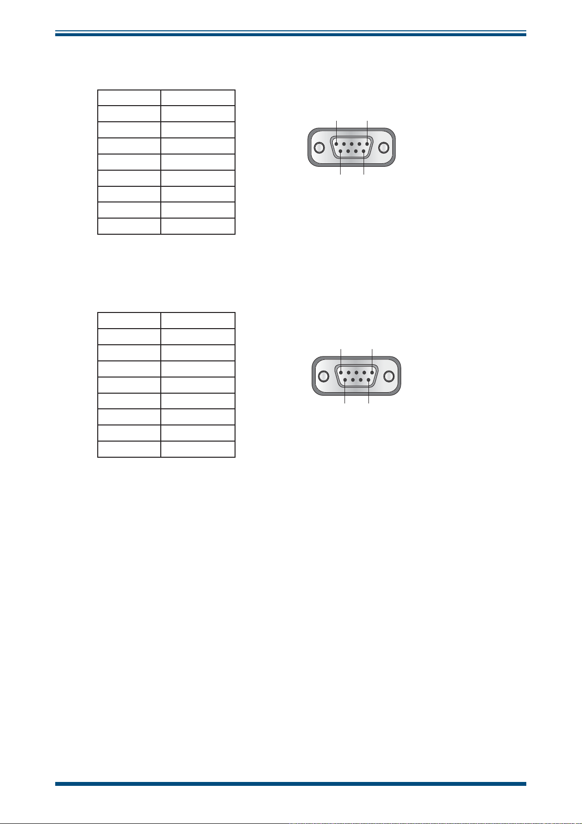
RS232
Pin 1 N/C
Pin 2 TXD
Pin 3 RXD
Pin 4 N/C
Pin 5 GND
Pin 6 N/C
Pin 7 N/C
Pin 8 N/C
Pin 9 N/C
RS485
Pin 1 N/C
Pin 2 N/C
Pin 3 A
Pin 4 N/C
Pin 5 GND
Pin 6 N/C
Pin 7 N/C
Pin 8 B
Pin 9 N/C
S8000 User’s Manual
RS232 Pinout (9-pin female)
Pin 1
Pin 6
RS485 Pinout (9-pin female)
Pin 1
Pin 6
Pin 5
Pin 9
Pin 5
Pin 9
16 97488 Issue 4, August 2018
Page 27
S8000 User’s Manual
!
!
2.5.9 Connection of Gas Supplies
POSSIBLE INJURY! The tubing, valves and other apparatus
attached to this instrument must be adequate for the
maximum pressure which will be applied, otherwise physical
injury to the operator or bystander is possible.
Before connection or disconnection of the instrument to
and from the gas line it is essential to vent the system to
atmospheric pressure, otherwise severe injury could result.
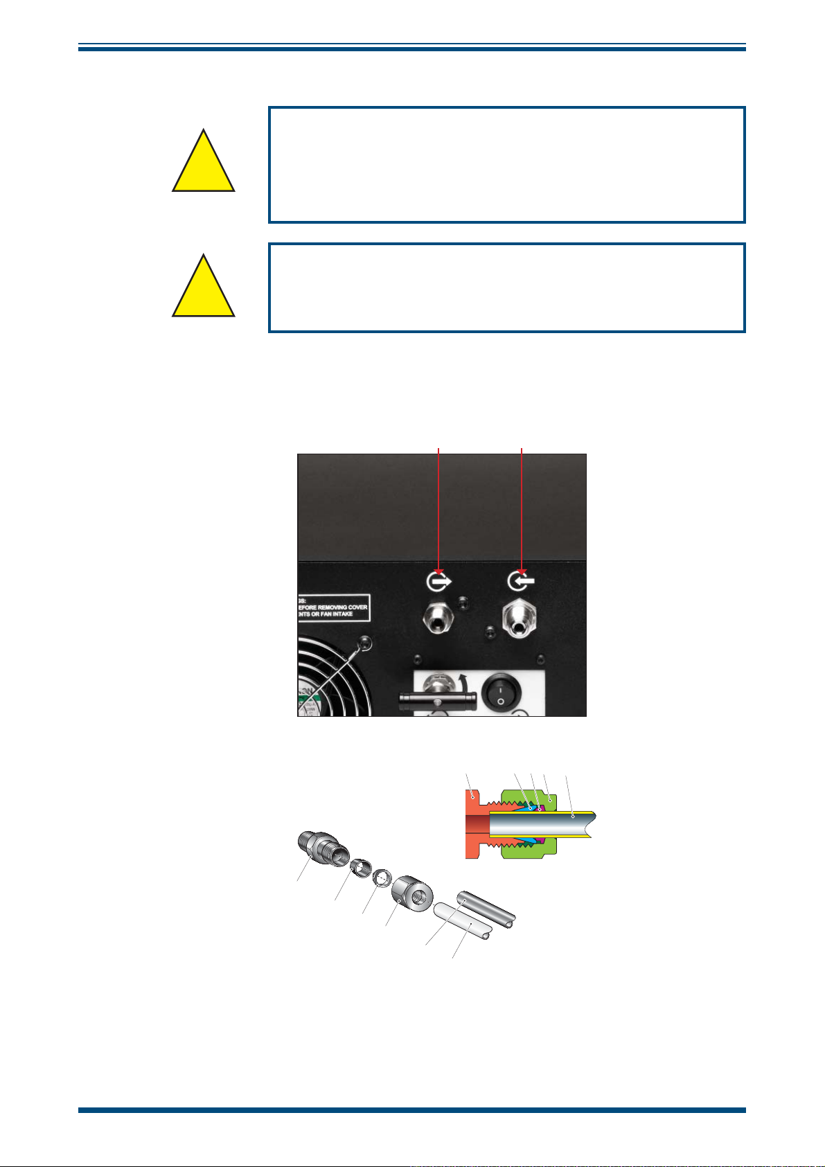
Sample gas connections are made via the GAS OUT port (7) and the GAS IN port (8)
located on the rear panel.
INSTALLATION
87
653
6
5
4
3
2
1
Figure 14
Michell Instruments 17
Gas Connections
4 1, 2
Page 28

INSTALLATION
The sample inlet and outlet connections are either 6mm or ¼" Swagelok® tube couplings
(optional). The gas input connection must be made with 6mm or ¼" stainless steel
tubing (the appropriate size for the connectors fi tted). The gas output connection for
most applications can just be exhausted to atmosphere via 300mm (11.8") of PTFE
tubing (1).
S8000 User’s Manual
The method of connection to the
1. Cut appropriate diameter stainless steel tubing (2) to the correct length
and, if necessary, bend to shape to suit the location of the instrument.
NOTE: To facilitate ease of connection to the port, at least 75mm
(3") of the tubing coming out of the
2. Clean off any burrs or metal shavings adhering to the tubing.
3. Pass the tubing (2) through the Swagelok nut (3).
4. Fit the back ferrule (4) over the tubing (2) with the bevelled end facing
the back of the front ferrule (5).
5. Place the front ferrule (5) over the tubing (2), bevelled end towards the
adaptor (6).
6. Push the tubing as far as it will go into the fi tting and tighten up the
locking nut (3) fi nger tight.
7. Hold the adaptor (6) fl ats with a wrench and tighten up the locking nut
(3) 1¼ turns. This action compresses the front ferrule (5) and back
ferrule (4) onto the tubing to form a gas tight seal. CAUTION: Do not
overtighten as this could cause the ferrules to crack and destroy
the integrity of the seal.
GAS IN port (8) is as follows.
GAS IN port should be straight.
8. Connect up the
in operations 1 - 8 above optionally using PTFE tubing (1) in place of
stainless steel (2).
GAS OUT port (7) in a similar manner to that described
18 97488 Issue 4, August 2018
Page 29

S8000 User’s Manual
2.6 Internal Sample Pump (Optional)
The internal sample pump can be used to allow measurement of static samples at
atmospheric pressure. The pump can be be routed in to the sample loop or bypassed,
depending on whether it is connected via the external tube link.
The instrument can be confi gured for operation with a pressurized sample by following
the instructions in Section 2.6.
To confi gure the instrument for sample pump operation (Atmospheric input pressure
only):
INSTALLATION
1. Connect the external tube link from the
port, and tighten to form a gas-tight seal
2. Connect the sample line to the
3. Use the needle valve on the pump panel to control the fl ow rate to 500ml/
min, as indicated on the display
GAS IN port
GAS OUT port, to the PUMP IN
Figure 15
Gas Connections when Pump is Fitted
Michell Instruments 19
Page 30

INSTALLATION
2.7 Conversion of S8000 to Rack Mount
S8000 User’s Manual
Figure 17
rack. To fi t the unit proceed as follows:
illustrates the method for fi tting a rack mount instrument into a standard 19”
Figure 16
1. Turn the unit on its left hand end and remove the four screws and washers
from the side panel.
2. Line up the fi xing holes on the right hand side of the instrument
with the corresponding holes in the right hand wing (fl ange facing
outwards).
3. Insert the four screws and washers through the wing and tighten
fi nger tight.
4. Ensure that the front fl ange is square to the front of the instrument
and tighten the screws.
5. Turn the unit on its right hand end and repeat operations 1 to 4.
To remove from the rack wings follow these directions above, in reverse.
Rack Fixing Method
20 97488 Issue 4, August 2018
Page 31

S8000 User’s Manual
3 OPERATION
As supplied, the S8000 is ready for operation and a set of default parameters has been
installed. This section describes both the general operation of the instrument and the
method of setting it up and changing the default parameters (see Appendix E) - should
this become necessary.
3.1 General Operational Information
While the instrument can physically operate in a fl owing gas stream of between 0.3 and
1 Nl/min, (0.6 and 2.1 scfh), Michell Instruments recommends operating at 0.5 Nl/min
(1.06 scfh) which is the fl ow-rate used during calibration. Operating at an alternative
rate could impact the instrument’s response time.
OPERATION
For all applications, the sample gas is taken into the instrument via the
located on the rear panel, from where it passes into a sample chamber. The gas fl ow rate
is then measured on the exhaust side of the sample chamber, prior to being exhausted
from the instrument via the
Within the sample chamber, the gas is passed over a Peltier chilled, gold-plated mirror.
The instrument’s internal control system maintains the drive to the Peltier heat pump to
ensure, by controlling the mirror temperature, that a level of condensate is maintained
on the mirror surface. The temperature of the mirror is then measured as the dew point.
After passing over the mirror, the sample gas is then typically exhausted to atmosphere
via the
The sampling chamber is available in two different confi gurations; low pressure and
high pressure. The low pressure version is designed to operate up to 1 barg (14.5 psig)
max and the high pressure version up to 20 barg (290 psig) max. When operating in
high pressure applications, a relevant gas sample line, representative of the product,
would be taken and fed into the instrument. In these applications, a metering valve
can be installed after the output port to maintain fl ow rate to within the instruments
operational limits.
When the sample to be measured is at atmospheric pressure, the [optional] sample
pump can be used to draw it through the instrument. Using the tube link provided,
the
adjusted using the integrated metering valve. The
outlet.
GAS OUT port.
GAS OUT port can be connected to the PUMP IN port. The fl ow rate can then be
GAS OUT port.
PUMP OUT port then becomes the
GAS IN port
The S8000 is suitable for the measurement of moisture content in a wide variety of
clean, non-corrosive gases. It will not contaminate high purity gases and is safe for use
in critical semi-conductor and fi ber optic manufacturing applications.
Michell Instruments 21
Page 32

OPERATION
A
-
5
-
C
MIN
OOL
S
SETU
.95
5.01
498
3.2 Instrument Display
The S8000 features a 5.7” color touch screen display.
S8000 User’s Manual
When the instrument is switched on an
menu system loads.
Initialising overlay will be shown while the
Figure 17
After the menu system has loaded, the Main Screen will show.
Dew Point
-34
Temperature
2
RH
71
A
Flow Rate
DCC ON
MAXC
Initialising Overlay Screen
79.
°C
80.5
°C
DP 0.00
Mode Hold
%
Next Mode 03:28:17
Process ON
Fault OFF
ml/min
Sensor Control
TANDBY
1
P
Figure 18
Main Screen
22 97488 Issue 4, August 2018
Page 33

S8000 User’s Manual
3.2.1 Main Screen
OPERATION
1
1
1
2
5 6 7 8
DCC OFF /
DCC ON
READOUTS
READOUTS
READOUTS
FLOW RATE
MAXCOOL /
Figure 19
MEASURE
Main Screen Layout
3
4
STANDBY /
OPERATE
STABILITY
GRAPH
OPERATIONAL
STATUS DISPLAY
No Name Description
Readouts
1
(Customizable)
These readouts display measured instrument parameters.
See Section 3.2.2 for additional information.
2 Flow Readout Displays fl ow rate in chosen units.
3 Stability Graph
Operational Status
4
Display
Displays a plot of the dew point over time.
Touch the readout once to enter full screen mode.
A detailed description of each item displayed in this area
is in Section 3.2.3.
Initiate a DCC cycle. See Section 3.4.1 for a detailed
5
DCC Button
explanation of the DCC function.
See Section 3.2.6 for DCC setup parameters.
6
MAXCOOL Button
7
STANDBY Button
Toggle
explanation of the
Switch between
When switching to
initiated.
MAXCOOL mode. See Section 3.4.2 for a detailed
MAXCOOL function.
MEASURE and STANDBY mode.
MEASURE mode a DCC cycle will be
See Section 3.4.6 for a detailed explanation of
mode.
Access to the Setup Menu.
8
SETUP Button
See Section 3.2.4 for more information about the setup
menu system.
SET UP
STANDBY
Table 3 Main Screen Description
Michell Instruments 23
Page 34

OPERATION
3.2.2 Customizable Readouts
The three readouts on the Main Screen can be confi gured by the user to show any of
the following parameters:
• Dew point
• Temperature
• Temperature – Dew point
• Relative Humidity, %RH
• Water Content (ppm
• Pressure *
* Pressure is only available as an option if a pressure transducer is installed in the
instrument
; ppmW; g/Kg; g/m3)
V
S8000 User’s Manual
The parameters displayed by default are Dew point, ppm
Follow these instructions to change the parameter:
1. Touch the readout once to enable parameter selection
2. Touch the left or right arrows to select the parameter to be displayed
3. Touch the center of the readout to confi rm selection
Full Screen Mode
Any of the readouts can be shown in full screen mode by touching and holding the
readout.
3.2.3 Operational Status Display
The Operational Status display includes the following:
Indicates data logging is enabled. Refer to Sections 3.2.7 and 3.4.4.
∆DP Represents the change in dew point over the stability time of the graph.
Mode
Next Mode
Process
Fault
Sensor
Reports current operational mode.
This will either be
Shows the time (in Hours:Minutes:Seconds) remaining until the transition
to the next mode of operation.
This two-state,
alarm is either
The process alarm can be set on any parameter (refer to Section 2.5.3).
Used to monitor the optical system and the degree of mirror contamination
During normal operation, with no fault conditions, this will read OFF. It
will be set to
measurement or if the mirror contamination exceeds 100% of the fi lm
thickness.
Indicates the operational mode of the sensor.
This can be either
ON if there is either a fault with the optics or dp temperature
and g/m3.
V
MEASURE, STANDBY, DCC, HOLD or MAXCOOL.
ON/OFF notifi cation indicates whether a parameter process
ON or OFF.
CONTROL, HEATING or COOLING.
Table 4 Operational Status Display
24 97488 Issue 4, August 2018
Page 35

S8000 User’s Manual
3.2.4 Setup Menu Screen
The Setup Menu is used to adjust the operational parameters of the instrument, change
the display setup and start or stop the data logging feature.
Initially, when the Setup Menu Screen is opened a set of labelled icons is displayed.
Touching one of these icons will take you to the appropriate submenu.
OPERATION
Figure 20
Once a submenu has been entered, parameters can be changed by touching the outlined
values. There are three types of input for editable values:
• Toggle Button – Touching the outlined value will switch between predefi ned
states, i.e. On/Off or Auto/manual.
• List Selection – A list of options will be displayed for the user to select.
• Numeric Input – Touching the outlined value will bring up the numeric
keypad (see following page).
Setup Menu Screen
Michell Instruments 25
Page 36

OPERATION
Numeric Input
When entering a numeric value a virtual keypad will be displayed.
S8000 User’s Manual
789
4
1
0
Figure 21
56
2 3
OK
Virtual Keyboard
C
The allowable range will initially be shown at the top of the keypad, e.g. 0 50
Some parameters can be disabled by entering a value of 0, this will be indicated by
0[off] 50
•
• Backspace
•
•
Leaving Menus
26 97488 Issue 4, August 2018
Clear Input
C
Cancel input
OK
Save input
To return from a menu or to cancel a numeric input, touch the exit icon.
Page 37

S8000 User’s Manual
3.2.5 Menu Structure
OPERATION
MAIN SCREEN
DCC
Display Hold
Period
Reset Optics
Setpoint
Interval
Output Hold
LOGGING
Status
Filename
Interval
OUTPUT
Output Select
Output Type
Parameter
Minimum
Maximum
ALARM
Parameter
Setpoint
Figure 22
DISPLAY
Resolution
Primary Unit
Pressure Unit
Stability
FAST
PRT Mode
Language
Backlight
Menu Structure
CLOCK ABOUT HELP
Date
Time
Network Settings
IP Address
Subnet Mask
Default Gateway
Press to return to
Press for more
?
Main Screen
information
Michell Instruments 27
Page 38

OPERATION
3.2.6 DCC
S8000 User’s Manual
Figure 23
Parameter Description
Display Hold
Period
Reset Optics Triggers a reset of the optical signal level on the next DCC cycle.
Set point
Interval
Output Hold
Holds the values on the display while the instrument is in
Available Input: On/Off
Duration of the DCC cycle.
Available Input: 1 to 59 minutes
Mirror heating temperature above measured dew point during DCC cycle.
Available Input: 10 to 40°C (50 to 104° F)
Time between automatic DCC cycles.
Available Input: 1-99 hours. Set to 0 to disable automatic DCCs
Time to hold the output at the last measured value after fi nishing a DCC
cycle.
Available Input: 1 to 59 minutes
Table 5 DCC Parameters
DCC Screen
HOLD mode.
28 97488 Issue 4, August 2018
Page 39
S8000 User’s Manual
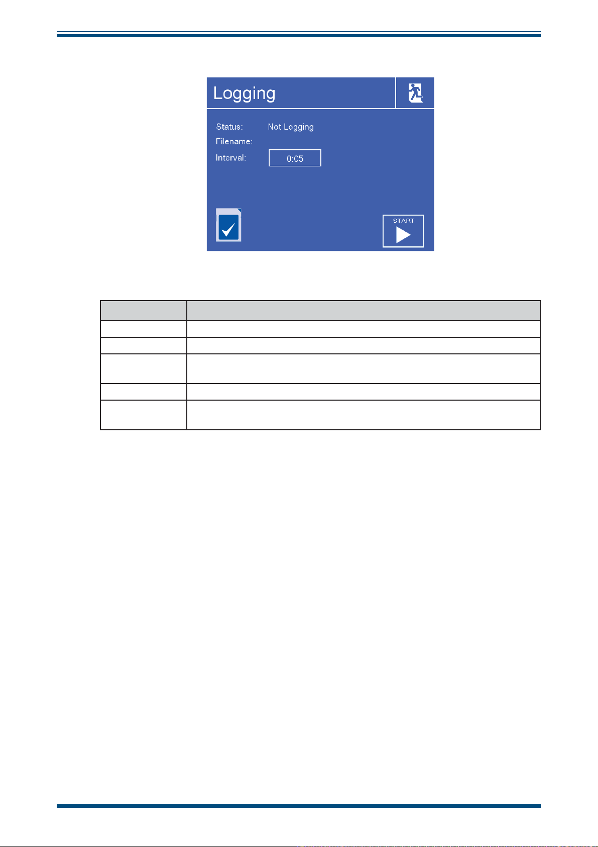
3.2.7 LOGGING
OPERATION
Figure 24
Parameter Description
Status Displays the status of the current logging operation.
Filename Displays the fi lename of the current log fi le.
Interval
SD Card Icon Shows the SD card status - refer to Table 7.
START/STOP
Button
Time in seconds between recording readings in the log fi le.
Available Input: 5 to 600 seconds
Automatically generates a new fi le name based on current time and
date - Starts logging at specifi ed interval.
Table 6 Logging Parameters
Logging Screen
Michell Instruments 29
Page 40

OPERATION
The table below explains the status of the SD card. The icon is shown in the bottom left
hand corner of the Logging screen.
S8000 User’s Manual
Icon Description
SD Card not fi tted
Insert SD Card
Initializing SD Card
Wait before attempting to start logging
ª
110001
010001
001011
SD Card ready to start logging
SD Card locked/write protected
Remove the SD Card and set the write-protect switch on the top left
side of the card to the
UP position
SD Card is currently being written to
Do not remove the SD Card or power off the instrument
Logging in progress
Do not remove the SD Card or power off the instrument
SD Card error
Hardware error
Contact Michell Instruments' service department
Table 7 SD Card Status Indicators
30 97488 Issue 4, August 2018
Page 41

S8000 User’s Manual
3.2.8 OUTPUTS
OPERATION
0
Parameter Description
Output Select
Output Type
Selects the output to be adjusted.
Available Input: Output 1, 2 or 3
Selects the type of analog output signal to use.
Available Input: 4-20 mA/0-20 mA/0-1 V
The parameter used to control the selected output.
Parameter
Available Input: g/m
barg, kPa, MPa, ml/min
Minimum
Maximum
The minimum output range for the selected parameter.
Available Input: Dependent on parameter
The maximum output range for the selected parameter.
Available Input: Dependent on parameter
Table 8 Outputs Parameters
% RH
Figure 25
100
Outputs Screen
3
, g/Kg, T-DP, DP, %RH, ppmV, ppmW, T, psig,
3.2.9 ALARM
Parameter Description
Parameter
Set point
Figure 26
Alarm Screen
The parameter used to control the process alarm.
Available Input: g/m
3
, g/Kg, T-DP, DP, %RH, ppmV, ppmW, T, psig,
barg, kPa, MPa, ml/min
Set point that triggers the alarm relay to activate.
Available Input: Dependent on parameter
Table 9 Alarm Parameters
Michell Instruments 31
Page 42

OPERATION
3.2.10 DISPLAY
S8000 User’s Manual
Parameter Description
Number of decimal places used when displaying parameters on the
Resolution
Primary Unit
Pressure Unit
Stability
FAST
PRT Mode
Language
Backlight
Main Screen.
Available Input: 1, 2, 3
Temperature unit to be used on the display and menus.
Available Input: ºC / ºF
Pressure unit to be used on the display and menus.
Available Input: psig, barg, kPa, MPa
Time scale in minutes for the Stability Graph on the Main Screen.
Available Input: 1 to 600 minutes
Enables or disables the Frost Assurance System Technology.
See Section 3.4.5.
Available Input: OFF / ON
If required for the calibration process or for external monitoring, the
internal PRT (optional) can be made available for external connection
via the 4 banana sockets on the back of the instrument.
Please note that this will disable the internal PRT measurement circuit
of the instrument.
Available Input: INTERNAL / EXTERNAL
Selects the language used for the menu screens.
Available Input: English / German / Spanish / French / Italian /
Portuguese / American / Russian / Chinese / Japanese
The brightness of the backlight.
Available Input: 5 to 100%
Figure 27
Display Screen
Table 10 Display Parameters
32 97488 Issue 4, August 2018
Page 43

S8000 User’s Manual
3.2.11 CLOCK
OPERATION
Parameter Description
Date Current date.
Time Current time.
3.2.12 ABOUT (Network Settings)
When using an S8000 that is fi tted with an Ethernet module this page is accessible via
the About Screen.
Figure 28
Clock Screen
Table 11 Clock Parameters
192
168
1
2
255
Figure 29
255
168192
255
11
0
Network Settings Screen
Parameter Description
IP Address The IP address of the instrument.
Subnet Mask The subnet mask that determines what subnet the IP address is on.
Default
Gateway
The default gateway for network communication.
Table 12 Network Parameters
Michell Instruments 33
Page 44
OPERATION
3.3 Operational Functions
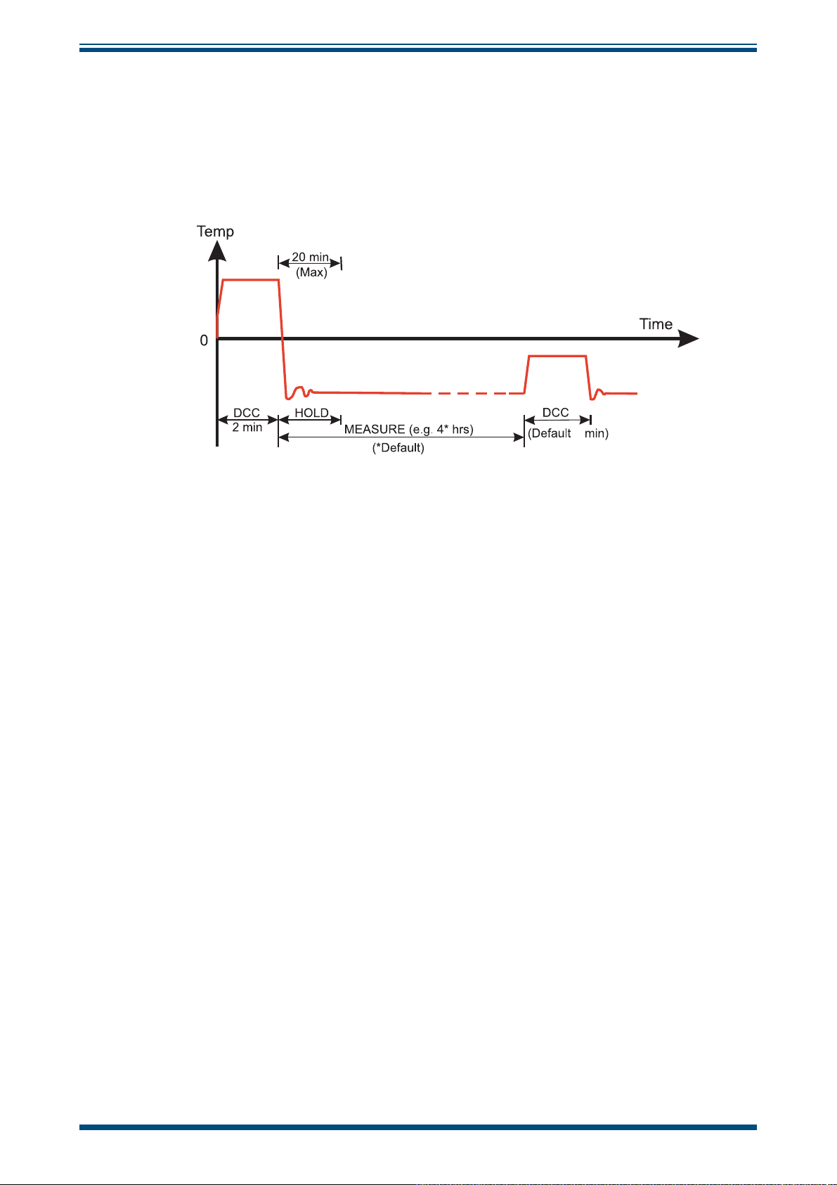
3.3.1 Operating Cycle
S8000 User’s Manual
The default parameters set up for the instrument defi ne an operating cycle, see
31.
2
Figure 30
At initial switch-on, the instrument enters a DCC cycle for 2 minutes. This heats the
mirror to a default temperature of +20°C (+36°F) above the previously measured value
- at the time of switch on this will be ambient temperature. This ensures that all moisture
is driven off the surface of the mirror.
Typical Operating Cycle
Figure
The mirror is maintained at this temperature for the DCC duration (default 2 minutes) or
2 minutes on switch-on. During the DCC process, Data Hold fi xes the analog outputs at
the value(s) read before DCC commenced. Data Hold typically lasts 4 minutes from the
end of a DCC cycle, or until the instrument has reached the dew point. This procedure
is in place to prevent any system which is connected to the outputs from receiving a
'false' reading.
After the DCC period has fi nished, the measurement (
during which the control system decreases the mirror temperature until it reaches the
dew point. The sensor will take a short amount of time to settle on the dew point. The
length of this stabilization time depends upon the temperature of the dew point. When
the measurement is stable the Status area of the display will indicate
The end of a DCC cycle re-sets the interval counter, meaning that another DCC will start
(by default) in 4 hours time. Once the measurement is stable,
the analog outputs will resume their normal operation. At this point the
the display will change to
MEASURE.
MEASURE) period commences,
CONTROL.
HOLD will release, and
STATUS area of
34 97488 Issue 4, August 2018
Page 45

S8000 User’s Manual
3.4 Operating Guide
3.4.1 DCC - Dynamic Contamination Control
Dynamic Contamination Control (DCC) is a system designed to compensate for the loss
of measurement accuracy which results from mirror surface contamination.
OPERATION
During the
the dew point to remove the condensation which has formed during measurement.
The surface fi nish of this mirror, with the contamination which remains, is used by the
optics as a reference point for further measurements. This ensures the accuracy of the
instrument is unaffected by any loss of refl ectivity due to wear or contamination of the
mirror.
After switch-on, the mirror is assumed to be clean, therefore the instrument will only
run a
every subsequent
hours.
At certain times it may be desirable to disable the
from interrupting a measurement cycle, e.g. during a calibration run. However, the DCC
functionality is important to the continued accuracy and stability of the instrument and
should not be permanently disabled.
A manual
Screen. The DCC button is context sensitive, i.e. if
DCC process the mirror is heated to a default temperature of 20°C above
DCC for 2 minutes to quickly establish a clean mirror reference point. By default,
DCC is 4 minutes in duration and will automatically occur every 4
DCC function in order to prevent it
DCC can be initiated or cancelled by touching the DCC button on the Main
DCC is on, the Main Screen shows
DCC OFF as being selectable. Similarly if DCC is off, DCC ON is shown.
It is possible to change the parameters relating to the
Screen, refer to Section 3.2.6.
DCC cycle on the DCC Setup
Michell Instruments 35
Page 46

OPERATION
3.4.2 MAXCOOL Function
The MAXCOOL function over-rides the dew-point control loop and applies maximum
cooling drive to the Peltier heat pump. It can be used to determine:
• the lowest temperature the mirror can be driven down to with reference
to the sensor body. This temperature is indicated on the display.
• whether or not the instrument is controlling at the dew point and
whether it is able to reach it. This situation could, for instance, arise
when attempting to measure very low dew points where, possibly due to
a high ambient temperature, the Peltier heat pump is unable to depress
the mirror temperature low enough to reach the dew point.
S8000 User’s Manual
• whether the instrument is controlling by switching
short period and then switching back to
mirror temperature briefl y and when it is switched back to
control loop should be able to stabilize the mirror temperature at the dew
point again.
MAXCOOL function can be turned on by touching the MAXCOOL button on the
The
Main Screen.
3.4.3 Pressure Compensation
As an option, the S8000 instrument can be fi tted with an internal pressure sensor that
measures the sample gas pressure. The pressure measured by this sensor is then used
internally as the basis for compensation for all of the pressure related parameters,
ppmV, ppmW, g/m3 and g/Kg. If a pressure transducer is not fi tted 101.3 kPa is used as
the basis of all these calculations. The internal pressure transducer is ranged 0 to 25
bara (0 to 363 psia).
3.4.4 Data Logging
The data logging function allows all of the measured parameters to be logged at a
user specifi ed interval on the supplied SD card via the SD card slot on the front of
the instrument. The fi lename for each log fi le is generated automatically from the
instrument date and time.
MAXCOOL on for a
MEASURE. This will depress the
MEASURE the
Log fi les are saved in CSV (comma separated value) format. This allows them to be
imported easily into Excel or other programs for charting and trend analysis. To set-up
data logging refer to Section 3.2.7.
36 97488 Issue 4, August 2018
Page 47

S8000 User’s Manual
3.4.5 Frost Assurance System Technology (FAST)
Theoretically, it is possible for water to exist as a super-cooled liquid at temperatures
down to -40°C (-40°F).
A gas in equilibrium with ice is capable of supporting a greater quantity of water vapor
at a given temperature than a gas in equilibrium with liquid water. This means that a
measurement below 0°C taken over water will read approximately 10% lower than the
same measurement taken over ice.
OPERATION
When turned on and
If the initial measurement is between 0°C and -40°C then the mirror is driven down
to below -40°C to ensure the formation of ice on the mirror surface. The instrument
then continues operation as normal – once ice has formed it will remain as ice until the
temperature is raised above 0°C (+32°F).
If required, the instrument’s
disable the
3.4.6 STANDBY Mode
This function is used for applications where the dew point of the sample gas changes
very quickly from dry to wet, creating conditions which may cause the sensor to saturate.
Alternatively it may be used in applications requiring infrequent manual measurements
to be taken, where it is preferable to have the sensor disabled between measurements.
STANDBY mode, drive to the Peltier heat pump is removed. While STANDBY mode
In
is enabled the sensor temperature will remain constant.
The main use for this feature is during set up (when measurements are not required),
i.e. when fl ow rates are being adjusted and the analog outputs are being confi gured.
FAST function, refer to Section 3.2.10.
FAST is enabled, the S8000 makes an initial dew point measurement.
FAST function can be switched on and off. To enable or
Michell Instruments 37
Page 48
APPLICATION SOFTWARE
4 APPLICATION SOFTWARE
The S8000 features Modbus over USB, RS232/485 or Ethernet, depending on which
option was ordered. A copy of the application software is supplied on a CD with the
instrument.
The application software is also available from the support section of the Michell
Instruments' website at: http://www.michell.com/uk/support/sware-downloads.htm
4.1 Installation
1. Extract the contents of the supplied zip fi le to a suitable location.
2. Close all currently running Windows programs.
3. Launch the installer and follow the on-screen instructions.
S8000 User’s Manual
4. The installer will ask for an authorization code, enter
5. Restart the PC to complete the installation.
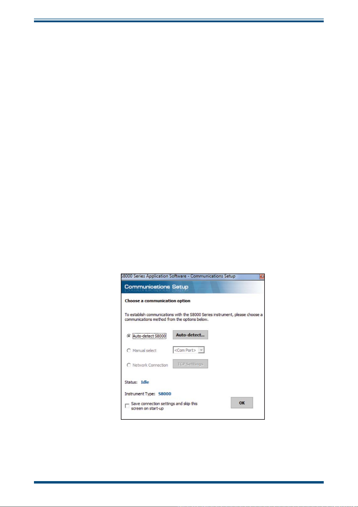
4.2 Establishing Communications
When launching the application software, the Communications Setup screen will be
displayed. The following sections explain how to establish communication with the
S8000, depending on whether it is fi tted with a USB, RS232/485 or Ethernet module.
7316-MIL1-8000.
Figure 31
Communications Setup Screen
38 97488 Issue 4, August 2018
Page 49

S8000 User’s Manual
4.2.1 USB Communication
1. Connect the S8000 to the PC using the supplied USB cable.
2. Windows will recognize the instrument and automatically install
the relevant drivers. If the driver installation has been successful
then the Windows Device Manager will list the following driver (see
Figure 33)
Michell Instruments USB to UART Bridge Controller
3. Launch the application software and choose one of the following
types of connection:
Auto Detect – The application software will attempt to fi nd the correct
COM port automatically.
Manual – Choose the appropriate COM port from the drop down list,
as shown in the Windows Device Manager Screen
:
APPLICATION SOFTWARE
.
4. Click the OK button to proceed to the next screen.
Figure 32
Windows Device Manager Screen
Michell Instruments 39
Page 50

APPLICATION SOFTWARE
4.2.2 RS232/485 Communication
1. Connect the instrument to the PC using the supplied RS232/485 cable.
2. If an RS232/485 port is present locally on the PC, then its COM port can
be identifi ed using Windows Device Manager. If an RS232/485 to USB
converter is being used, then it will be assigned its own COM port.
S8000 User’s Manual
3. Launch the application software and choose
4. Choose the appropriate COM port from the drop down list, as shown in
the Windows Device Manager Screen.
5. Click the
4.2.3 Ethernet Communication
1. Confi gure the network settings of the instrument. Refer to Section 3.2.12.
2. Connect the S8000 to the network using the supplied Ethernet cable.
3. Launch the application software and choose the Network Connection
option.
4. Click the
5. Click the
then proceed to the next screen by clicking the
check network settings and try again.
OK button to proceed to the next screen.
TCP Settings button to enter the IP address of the instrument.
Test button. If communication with the instrument is successful
manual.
OK button, otherwise
Figure 33
Network Settings Screen
40 97488 Issue 4, August 2018
Page 51

S8000 User’s Manual
4.3 Data Acquisition or Edit Variables Mode
Once communication has been established, the Options Screen is displayed.
APPLICATION SOFTWARE
Figure 34
Options Screen
Michell Instruments 41
Page 52

APPLICATION SOFTWARE
4.3.1 Data Acquisition
This mode of operation allows all measured instrument parameters to be graphed and
logged in real time.
S8000 User’s Manual
Figure 35
Data Acquisition Control Toolbar
Data Acquisition Screen
Name Description
Run
Pause Pause data acquisition
Stop Stop data acquisition
Plot and log interval Time in seconds between graph and log fi le updates
Log fi lename
DCC
MAXCOOL
Begin data acquisition and logging
A fi lename must be fi rst be selected to enable data logging
Path and fi lename of the log fi le
Click the small folder icon next to this text box to create a new
log fi le
Initiate a DCC cycle
Refer to Section 3.4.1 for detailed information on the DCC
function
Toggle between MAXCOOL and MEASURE mode
Refer to Section 3.4.2 for detailed information on the
function
MAXCOOL
Toggles between STANDBY and MEASURE mode
STANDBY
Table 13 Data Acquisition Control Description
Refer to Section 3.4.6 for detailed information on the STANDBY
function
42 97488 Issue 4, August 2018
Page 53

S8000 User’s Manual
Instrument readings and status
This area displays all measured instrument parameters and shows the status of the
Fault, Process and Sensor Cooler Alarm.
Graph Controls
Name Description
Plot Automatically advances the graph as new data is acquired
Dragging the mouse on the graph scrolls along the time axis
Scroll Time
Zoom Time
Scroll Y
Zoom Y
Zoom Box Zooms in on both axes in the user selected area
Show time/Y
Options Displays the chart options window
Copy Copies the chart to the clipboard as a bitmap fi le
Drag to the left to scroll forwards
Drag to the right to scroll backwards
Dragging the mouse on the graph changes the scale of the time axis
Drag to the left to increase the scale size
Drag to the right to decrease the scale size
Dragging the mouse on the graph scrolls along the Y axis
Drag down to scroll up
Drag up to scroll down
Dragging the mouse on the graph changes the scale of the Y axis
Drag up to increase the scale size
Drag down to decrease the scale size
Select a parameter from the legend on the right hand side of the graph
Dragging the mouse along the graph will move the vertical cursor
along the time axis
The Y value for the selected parameter at the position of the cursor
will be displayed above the graph
APPLICATION SOFTWARE
Table 14 Graph Control Description
Graph
Plots the parameters selected by the user in the chart options window.
Status Bar
Name Description
Acquisition
state
Number of
readings
Next reading
countdown
Log fi le Full path of the log fi le (if specifi ed)
Indicates whether data acquisition is running, paused or stopped, with
the messages RUNNING, PAUSED or IDLE
Number of readings taken since starting the current acquisition session
Countdown timer (in seconds), which indicates when the next reading
will be taken
Table 15 Status Bar Description
Michell Instruments 43
Page 54

APPLICATION SOFTWARE
4.3.2 Variable Edit
The variable edit mode allows the instrument confi guration to be changed through the
application software. On launch, it will automatically read and display the current values
of each of the instrument variables.
Note: The variables are not periodically updated on-screen. To obtain up-todate values, click the Read button.
Editing variables
To edit a variable, fi rst click on it to highlight it.
If the variable has a fi xed list of options, a drop-down arrow will appear in the right-
hand column. Choose a new value from the drop-down list provided.
If the variable does not have a fi xed list of options, type the new value into the right-
hand column text input area.
S8000 User’s Manual
NOTE: The variable background colour will turn pink to indicate it has been
changed on-screen and is pending upload to the instrument.
Click the Write button to upload changed values to the instrument.
NOTE: Variable values and formatting are checked by the application software
before they are uploaded to the instrument.
A message box will report any errors found.
Once a modifi ed value has been written to the instrument, the background colour will
return to white.
44 97488 Issue 4, August 2018
Page 55

S8000 User’s Manual
APPLICATION SOFTWARE
Figure 36
Variables Editor Screen
Michell Instruments 45
Page 56

MAINTENANCE
!
DANGER
Electric
Shock Risk
5 MAINTENANCE
There are no user-serviceable parts on the S8000, other than the removal and
replacement of the AC power supply fuse and cleaning the mirror in the sensor.
5.1 Safety
S8000 User’s Manual
This equipment operates from power supply voltages that
can be lethal and at pressures (depending upon application)
that could cause injury.
Ensure that any test installation meets the standards
described in Section 2.3 of this manual.
Under NO circumstances should the instrument case be
removed or the air vents covered or in any way restricted.
Maintenance and repair, other than that described in this
section, must only be carried out by trained personnel and
the instrument should be returned to the manufacturer for
this purpose.
46 97488 Issue 4, August 2018
Page 57

S8000 User’s Manual
5.2 Fuse Replacement
If the instrument fails to operate after it has been connected to an AC power supply (85 to
264 V AC, 47/63 Hz) and switched on, proceed as follows:
1. If the power supply cable is fi tted with a fused plug, switch off the power
supply, remove the plug, check and, if necessary, replace the fuse. If the
instrument still fails to operate, after fi tting the fuse and switching the
power supply on, proceed as follows (see
73
74
75
71
Figure 38)
MAINTENANCE
.
72
Figure 37
2. Switch the instrument’s ON/OFF switch (1) to OFF, isolate the external
power supply and remove the IEC power connector (2) from the
instrument’s power socket (3). NOTE: If access to the rear of the
instrument is restricted, e.g. if the instrument is a rack mounted
model, it may be necessary to remove the instrument from the
rack (refer to Section 2.77).
3. Locate the fuse carrier (4) and pull it out of the connector housing (5). A
small screwdriver inserted under the lip may be useful in order to lever
it out.
4. Replace the fuse cartridge (6). NOTE: It is essential that a fuse of
the correct type and rating is fi tted to the instrument (20mm,
T-type (2.5 A anti-surge).
5. Fit a new fuse cartridge (6) into the fuse carrier (4) and push the fuse
carrier (4) back into the power connector housing (5).
6. Push the IEC power connector (2) back into the power socket (3), turn
on the external power supply and switch on the instrument (1). Check
that the instrument is now operational. If the fuse blows immediately
on switch-on either contact the manufacturer or their service agent. DO
NOT ATTEMPT ANY FURTHER SERVICING PROCEDURES.
Power Supply Fuse Replacement
Michell Instruments 47
Page 58

MAINTENANCE
!
5.3 Sensor Mirror Cleaning
Before removing the safety strap or opening the sensor
housing it is essential to vent the system to atmospheric
pressure, otherwise severe injury or damage to the
Throughout the life of the instrument, periodic cleaning of the mirror surface and optics
window may be required. The frequency of this depends upon operating conditions and
the potential in the application for contaminants to be deposited on the mirror. Sensor
cleaning is mandatory if the instrument indicates an optics fault. The cleaning procedure
is as follows:
S8000 User’s Manual
WARNING
equipment could result.
4
5
Figure 38
The cleaning procedure is as follows:
1. Switch off the instrument and unscrew the blanking plug from the
stainless steel sensor cover (1) on the front of the instrument.
2. Remove unscrew the large stainless steel cover (2).
3. Carefully remove the optics block (3) to reveal the mirror window
(4).
Sensor Mirror Cleaning
3
2
1
4. Insert the blanking plug (1) into the mirror window (4) to remove it.
48 97488 Issue 4, August 2018
Page 59
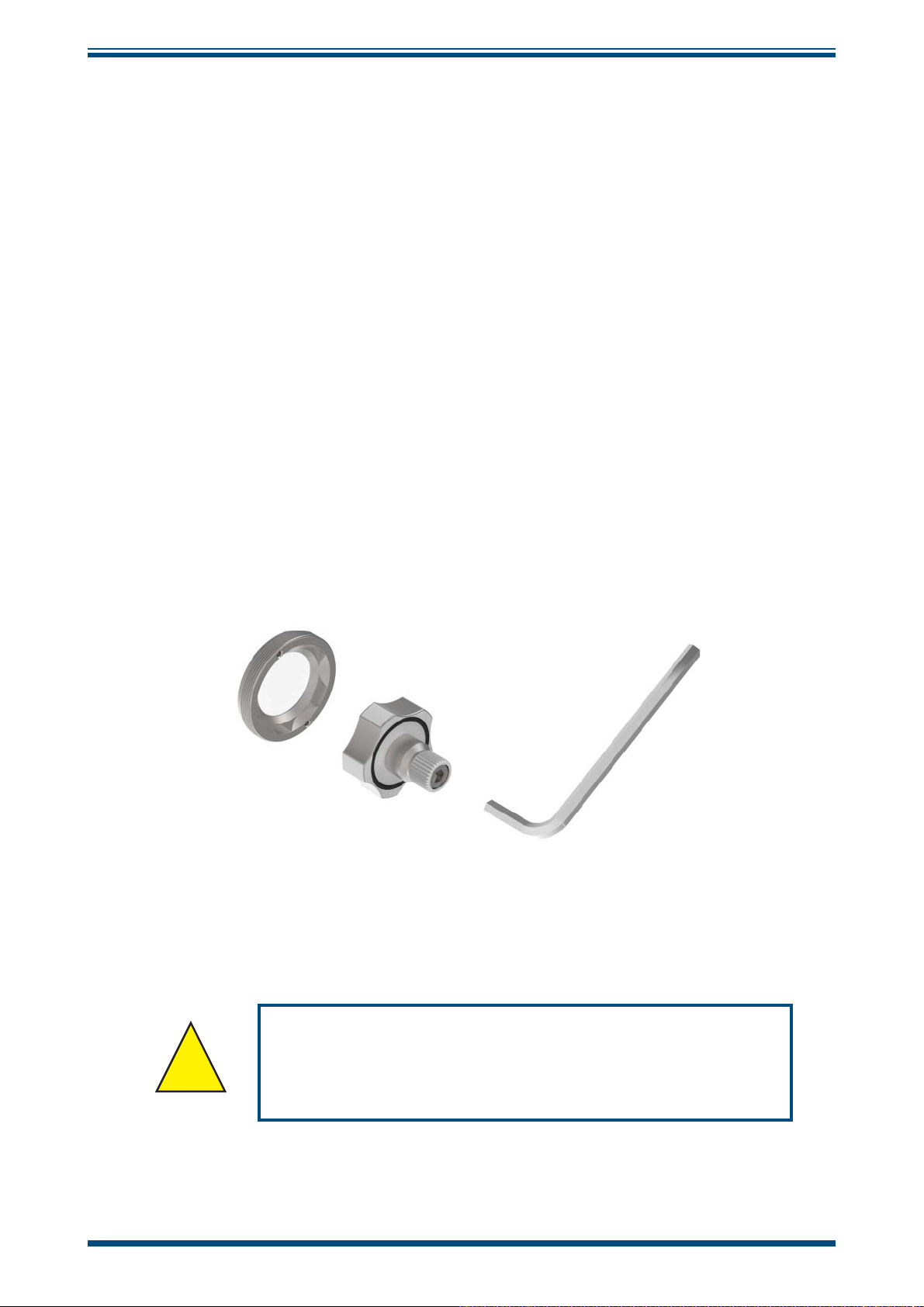
S8000 User’s Manual
5. Clean the mirror surface and optics window with a cotton bud/QTip soaked in distilled water. If the sensor has been exposed to
oil based contamination then use one of the following solvents:
methanol, ethanol, or isopropyl alcohol. To avoid damage to the
mirror surface do not press too fi rmly on the cotton bud/Q-Tip
when cleaning. Allow enough time for the cleaning solvent to fully
evaporate before reassembly.
6. Replace the items in the reverse order. Make sure when refi tting the
optics block to align the gold contacts on the block with the gold
contacts on the instrument.
7. Replace the large stainless steel cover, screwing it in fi rmly but
taking care not to overtighten it.
5.3.1 Releasing optics window
If the optics window is too tight to unscrew by hand (with the blanking plug) then use
the Allen key supplied to loosen.
MAINTENANCE
Figure 39
!
Michell Instruments 49
Never use the Allen key to tighten the optics window as
this may result in permanent damage to the instrument.
Releasing Optics Window
WARNING
Page 60

MAINTENANCE
5.3.2 Fitting the Microscope (Optional)
To observe the frost formation on the chilled mirror surface, an optional microscope
(Part No. S8K-RS-MCI) can be provided. The microscope allows direct viewing of the
mirror surface, providing assurance that ice crystals have formed and that supercooled
water is not present at temperatures below 0°C.
When the instrument is controlling at a dew point, condensation is seen as small, bright
red specks against a dark background. Liquid water is seen as rounded droplets and ice
as sharp edged crystals.
1. Remove the blanking plug and screw the microscope unit into the sensor
cap until about 6 threads remain showing.
S8000 User’s Manual
Figure 40
2. If the instrument is not operating, switch it ON and rotate the microscope
body until the mirror surface is brought into sharp focus. Two or three
extra turns either way are usually suffi cient.
3. To prevent stray light effects, always replace the blanking plug after
removing the microscope.
Fitting the Microscope
50 97488 Issue 4, August 2018
Page 61

S8000 User’s Manual
6 GOOD MEASUREMENT PRACTICE
The S8000 is designed to operate in a fl owing gas stream. The sampling chamber, which
enables a small sample of gas to be passed over a Peltier chilled, plated copper mirror,
is designed to operate at pressures up to 1 barg (14.5 psig) (low pressure version),
and up to 20 barg (290 psig) max (high pressure version). For many applications, or
when the internal sample pump is in use, the sample chamber operates at atmospheric
pressure with the sample gas being exhausted to atmosphere.
The sensor is designed for operation with fl ow rates of 0.3 and 1 Nl/min (0.6 and 2.1
scfh), although it will operate successfully at fl ow rates as low as 0.1 Nl/min (0.2 scfh).
It is important to ensure that the fl ow rate through the sample line, connecting the
source to the S8000, is high enough to avoid log time lags in response to humidity
changes at the sample source.
Ideally therefore, the fl ow rate should be set between 0.3 and 0.7 Nl/min (0.6 and
2.1 scfh), 0.5 Nl/min (1.06 scfh) [±0.2 Nl/min (±0.4 scfh) being the recommended
optimum]. For fl ow regulation purposes, by default, the
FLOW. Should the FRONT page not be showing FLOW, Section 3.2.2 details the
read
method of setting-up the instrument to display this parameter.
GOOD MEASUREMENT PRACTICE
FRONT page is confi gured to
Unless the optional sample pump is fi tted, fl ow regulation is not provided within the
S8000 instrument. Gas fl ow must therefore be regulated outside the instrument,
typically on the
needle valve. Always use high quality valve gear, coupling connections and pipework.
Avoid pressure gradients in the system by placing excessive fl ow restriction on the
side of the system. In applications where the test gas has a very high fl ow rate,
OUT
an instrument by-pass arrangement is preferable to a fl ow restrictor after the sensor.
GAS IN side for atmospheric measurements, by means of a precision
GAS
Michell Instruments 51
Page 62

GOOD MEASUREMENT PRACTICE
6.1 Sampling Hints
Measurement of moisture content is a complex subject, but does not need to be diffi cult.
This section aims to explain the common mistakes made in measurement situations, the
causes of the problem, and how to avoid them. Mistakes and bad practices can cause
the measurement to vary from the expectation; therefore a good sampling technique is
crucial for accurate and reliable results.
Transpiration and Sampling Materials
- 20
- 30
S8000 User’s Manual
- 40
- 50
Dew point (ºC)
- 60
- 70
12345
nickel
stainless steel
Time (hours)
nylon
copper
polyethylene
PTFE
All materials are permeable to water vapor, as the water molecule is extremely small
compared to the structure of solids, even when compared to the crystalline structure
of metals. The graph above shows the dew point inside tubing of different materials
when purged with very dry gas, where the exterior of the tubing is in the ambient
environment.
Many materials contain moisture as part of their structure, particularly organic materials
(natural or synthetic), salts (or anything which contains them) and anything which
has small pores. It is important to ensure that the materials used are suitable for the
application.
If the partial water vapor pressure exerted on the outside of a compressed air line is
higher than on the inside, the atmospheric water vapor will naturally push through the
porous medium causing water to migrate into the pressurized air line. This effect is
called transpiration.
Adsorption and Desorption
Adsorption is the adhesion of atoms, ions, or molecules from a gas, liquid, or dissolved
solid to the surface of a material, creating a fi lm. The rate of adsorption is increased at
higher pressures and lower temperatures.
Desorption is the release of a substance from or through the surface of a material. In
constant environmental conditions, an adsorbed substance will remain on a surface
almost indefi nitely. However, as the temperature rises, so does the likelihood of
desorption occurring.
In practical terms, as the temperature of the environment fl uctuates, water molecules
are adsorbed and desorbed from the internal surfaces of the sample tubing, causing
small fl uctuations in the measured dew point.
52 97488 Issue 4, August 2018
Page 63

S8000 User’s Manual
Sample Tubing Length
The sample point should always be as close to the critical measurement point as possible,
in order to obtain a truly representative measurement. The length of the sample line
to the sensor or instrument should be as short as possible. Interconnection points and
valves trap moisture, so using the simplest sampling arrangement possible will reduce
the time it takes for the sample system to dry out when purged with dry gas.
Over a long tubing run, water will inevitably migrate into any line, and the effects of
adsorption and desorption will become more apparent. It is clear from the graph shown
above that the best materials to resist transpiration are stainless steel and PTFE.
Trapped Moisture
Dead volumes (areas which are not in a direct fl ow path) in sample lines, hold onto
water molecules which are slowly released into the passing gas; this results in increased
purge and response times, and wetter than expected readings. Hygroscopic materials
in fi lters, valves (e.g. rubber from pressure regulators) or any other parts of the system
can also trap moisture.
GOOD MEASUREMENT PRACTICE
Sample Conditioning
Sample conditioning is often necessary to avoid exposure of sensitive measuring
components to liquids and other contaminants which may cause damage or affect the
accuracy over time, depending on the measurement technology.
Particulate fi lters are used for removing dirt, rust, scale and any other solids that may
be in a sample stream. For protection against liquids, a coalescing fi lter should be used.
The membrane fi lter is a more expensive but highly effective alternative to a coalescing
fi lter. It provides protection from liquid droplets, and can even stop fl ow to the analyzer
completely when a large slug of liquid is encountered.
Condensation and Leaks
Dewpoint > T Dewpoint < T
Maintaining the temperature of the sample system tubing above the dew point of the
sample is vital to prevent condensation. Any condensation invalidates the sampling
process as it changes the water vapor content of the gas being measured. Condensed
liquid can alter the humidity elsewhere by dripping or running to other locations where
it may re-evaporate.
The integrity of all connections is also an important consideration, especially when
sampling low dew points at an elevated pressure. If a small leak occurs in a high
pressure line, gas will leak out but vortices at the leak point and a negative vapor
pressure differential will also allow water vapor to contaminate the fl ow.
Michell Instruments 53
Page 64

GOOD MEASUREMENT PRACTICE
!
!
Flow Rates
Theoretically fl ow rate has no direct effect on the measured moisture content, but in
practice it can have unanticipated effects on response speed and accuracy. The optimal
fl ow rate varies depending on the measurement technology, and can always be found
in the instrument or sensor manual.
An inadequate fl ow rate can:
• Accentuate adsorption and desorption effects on the gas passing
through the sampling system.
• Allow pockets of wet gas to remain undisturbed in a complex sampling
system, which will then gradually be released into the sample fl ow.
• Increase the chance of contamination from back diffusion: ambient air
that is wetter than the sample can fl ow from the exhaust back into the
system. A longer exhaust (sometimes called a pigtail) can also help
alleviate this problem.
S8000 User’s Manual
• Slow the response of the sensor to changes in moisture content.
An excessively high fl ow rate can:
• Introduce back pressure, causing slower response times and
unpredictable effects on equipment such as humidity generators.
• Result in a reduction in depression capabilities in chilled mirror
instruments by having a cooling effect on the mirror. This is most
apparent with gases that have a high thermal conductivity such as
hydrogen and helium.
POSSIBLE INJURY! The tubing, valves and other apparatus
attached to this instrument must be adequate for the
maximum pressure which will be applied, otherwise physical
injury to the operator or bystander is possible.
Before disconnecting the S8000 from the gas line it is essential
to vent the system to atmospheric pressure, otherwise severe
injury could result.
54 97488 Issue 4, August 2018
Page 65

S8000 User’s Manual
7 CALIBRATION
7.1 Traceability
The calibration of this instrument is traceable to national standards. For this reason
the instrument can only be calibrated in an accredited e.g. NIST or UKAS accredited,
standards laboratory.
If these facilities do not exist, the instrument must be returned to the manufacturer,
Michell Instruments, or an approved agent (for contact information go to www.michell.
com).
If required for the calibration process, the instrument’s internal PRT can be made
available for external connection as described in Section 3.2.10.
DCC function can be disabled for calibration purposes (refer to Section 3.2.6).
The
A calibration certifi cate bearing a three point calibration is issued with each instrument.
If required, an option is available to add further specifi c calibration points. Contact
Michell Instruments for further information (for contact information go to www.michell.
com).
CALIBRATION
&(57,),&$7(2)&$/,%5$7,21
The under-mentioned item has been calibrated at the following points in the Michell Instruments’ Humidity Calibration
Laboratory against Test Equipment traceable to the NATIONAL PHYSICAL LABORATORY, Middlesex, United Kingdom and to
the NATIONAL INSTITUTE OF STANDARDS & TECHNOLOGY, Gaithersburg, Maryland, USA.
&HUWLILFDWH1XPEHU
7HVW'DWH
,QVWUXPHQW6HULDO1XPEHU
3URGXFW7\SH
*HQHUDWHG
'HZSRLQW
&RPPHQWV
&DOLEUDWLRQ3$667KHUHVXOWVDUHZLWKLQ VSHFLILFDWLRQDWWKHPHDVXUHGSRLQWV
7UDFHDELOLW\WR1DWLRQDO3K\VLFDO/DERUDWRU\LVRYHUWKHUDQJH&WR&
127(
7UDFHDELOLW\WR1DWLRQDO, QVWLWXWHRI6WDQGDUGVDQG7HFKQROR J\LVRYHUWKHUDQJH&WR&
8QFHUWDLQW\RIPHDVXUHPHQW
#&'3LQFUHDVLQJOLQHDUO\WR#&'3WKHQULVLQJOLQHDUO\WR#&'3
EHWZHHQ&'3DQG&'3
7KHXQFHUWDLQW\LVEDVHGRQDVWDQGDUGXQFHUWDLQW\PXOWLSOLHGE\DFRYHUDJHIDFWRUN SURYLGLQJDOHYHORIFRQILGHQFHRIDSSUR[LPDWHO\
$SSURYHG6LJQDWRU\
)HE
6,QWHJUDOH
°°°°
&
$FN1XPEHU
7HVW(TXLSPHQW
6HQVRU6HULDO1XPEHU
,QVWUXPHQW'LVSOD\
'HZSRLQW
°°°°
&
$
,QVWUXPHQW'LVSOD\
&RUUHFWLRQ&
4
)HE
Michell Instrumen ts Ltd.
Figure 41
www.michell.com
Typical Calibration Certifi cate
Michell Instruments 55
Page 66
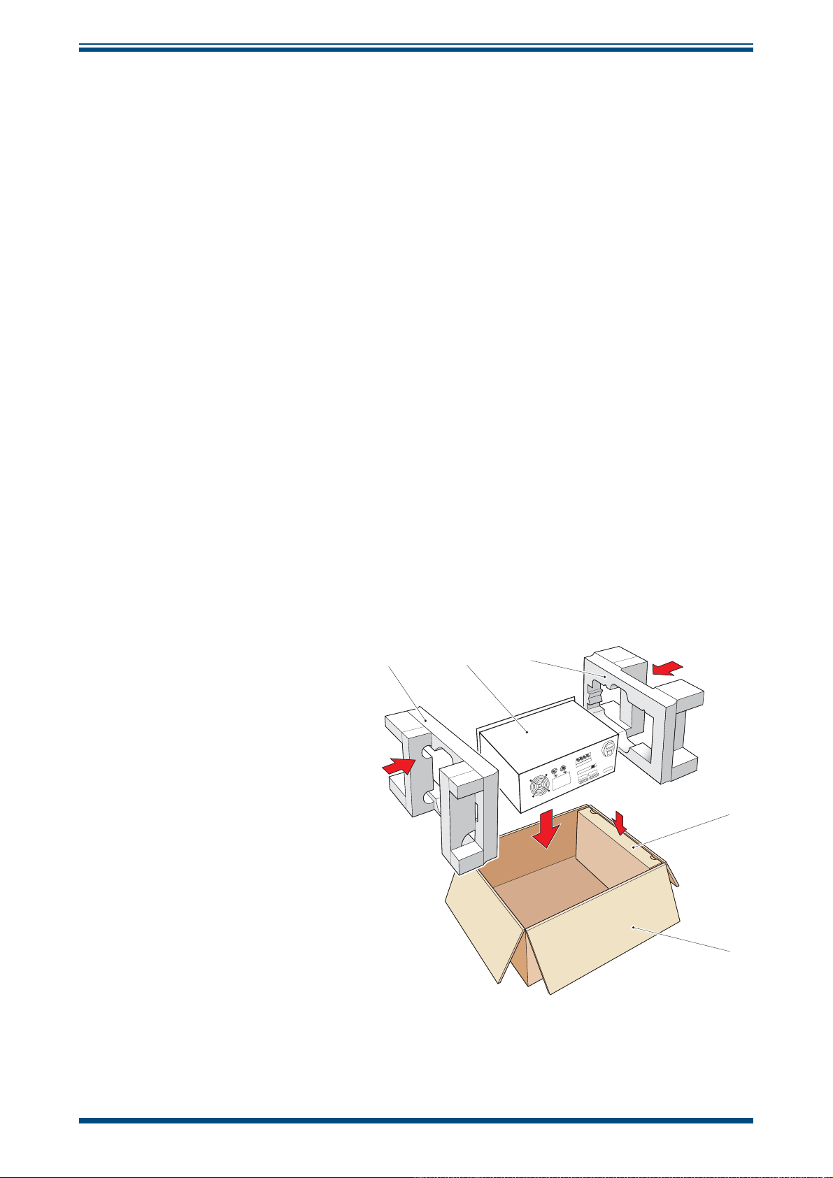
PREPARATION FOR SHIPPING
8 PREPARATION FOR SHIPPING
For shipping purposes, the instrument should be packed into its original carton, the
latter providing the recommended degree of protection during transit. To prepare the
instrument for shipping, proceed as follows.
1. Switch off the instrument and remove the power supply cable (see Section
2.5.1). If the instrument is rack mounted, fi rst remove it from the rack,
and remove the rack mount wings.
2. Remove the (optional) microscope and re-fi t the blanking plug.
3. Remove the (optional) remote PRT (see Section 2.5.4).
4. If fi tted, remove the USB communications cable (see Section 2.5.6).
5. Remove the analog and alarm output connectors (see Section 2.5.2 and
Section 2.5.3).
6. Remove any connections to the 4-wire PRT output binding posts (see
Section 2.5.5).
S8000 User’s Manual
7. Remove the connections to the
GAS IN and GAS OUT ports (see Section
2.5.99).
8. Pack the instrument in its original case as shown in
Figure 41.
NOTE: The
accessories should be packed in the box (4). Unless returning
for repair, it is not necessary to return either the microscope or
the analog and alarm connectors. All cables and the remote PRT
probe (if supplied) should be returned for checking.
9. Enclose a packing list detailing all equipment contained in the box and
seal the box. Ideally, for extra security, the box should be banded.
1
23
4
1 Side packing
2 S8000 Instrument
3 Side packing
4 Accessories box
5
5 Carton
Figure 42
Instrument Packing Details
56 97488 Issue 4, August 2018
Page 67

S8000 User’s Manual
APPENDIX A
Appendix A
Technical Specifi cations
Michell Instruments 57
Page 68

APPENDIX A
Appendix A Technical Specifi cations
Dew-Point Sensor Performance
Measurement Technology Chilled Mirror
Accuracy ±0.1 °C (±0.18 °F)
Reproducibility ±0.05°C (±0.09°F)
-60 to +40°Cdp (-76 to +104 °Fdp)
Measurement Range
S8000 User’s Manual
Operating Temperature
Range
Operating Pressure
Sample Flow Rate
Detection System
-20 to +40°C (-4 to +104 °F)
Low Pressure Version: 0 to 1 barg (0 to 14.5 psig)
High Pressure Version: 0 to 20 barg (0 to 290 psig)
0.1 to 1 Nl/min (0.2 to 2.1 scfh)
RRS Triple Detection
Remote PRT Probe (Optional)
Temperature Measurement 4 wire Pt 100, 1/10 DIN class B
Measurement Accuracy ±0.1 °C (±0.18 °F)
Cable Length 2m (6.6ft) (250m (820ft) max)
Flow Sensor
Measurement Accuracy
Measurement Range
Typical ±5% uncalibrated
0 to 1000 ml/min
Integrated Pressure Sensor (Optional)
Measurement Range 0 to 25 bara (0 to 377 psia)
Measurement Accuracy 0.25% Full Scale
Measurement Units psia, bara, KPa or MPag
58 97488 Issue 4, August 2018
Page 69

S8000 User’s Manual
Monitor
Resolution User-selectable to 0.001 dependant on parameter
APPENDIX A
Measurement Units
Outputs
HMI 5.7" LCD touchscreen with white on blue graphics
Data Logging
Environmental Conditions -20 to +40°C (-4 to +104° F)
Power Supply 85 to 264 V AC, 47/63 Hz
Power Consumption 100 VA
EMC - Class A Emissions
Industrial Location Immunity
°C and °F for dew point and temperature
%RH, g/m
Analog: 3 channels, user-selectable 4-20 mA, 0-20 mA or 0-1 V
Digital: Modbus RTU over USB, and optional Modbus RTU over
RS232, RS485 or Modbus TCP over Ethernet
Alarm: Two volt free changeover contacts, one process alarm, one
fault alarm; 1 A @ 30 V DC
SD Card (512 Mb supplied) and USB interface
SD Card (FAT-32) - 32Gb max. that allows 24 million logs or 560
days, logging at 2 second intervals
Complies with EN61236:1997 (+A1/A2/A3)
3
, g/kg, ppmV , ppmW (SF6), for calculated humidities
Mechanical Specifi cations
Dimensions 184 x 440 x 343mm (7.3 x 19 x 14.5") h x w x d
Weight 11.4kg (25.1lb)
General
Process connections 6mm Swagelok® (MALE) or 1/4” Swagelok® (MALE)
Storage Temperature -40 to +50°C (-40 to +122 °F)
Calibration
3-point traceable in-house calibration as standard
UKAS accredited calibrations optional - please consult Michell
Michell Instruments 59
Page 70

APPENDIX A
A.1 Dimensions
S8000 User’s Manual
186.9 mm
7.358 ins
178.5 mm
7.028 ins
34 mm
1.337 ins
440.0 mm
17.323 ins
342.9 mm
13.498 ins
46.0 mm
1.811 ins
177.0 mm
7.0 ins
144.5 mm
5.689 ins
60 97488 Issue 4, August 2018
Page 71

S8000 User’s Manual
APPENDIX B
Appendix B
Formatting SD Cards
Michell Instruments 61
Page 72

APPENDIX B
Appendix B Formatting SD cards
Before an SD card can be used for the storage of datalog results it must fi rst be
formatted. Initially the card must be connected to a card reader which must, in turn, be
connected to the host computer. Most proprietary card readers connect to the host via
a USB port. Almost all laptop/notebook PC’s are equipped with an SD card reader slot.
The formatting procedure is as follows:
1. Insert the card into the card reader and open
Windows Explorer. The card will be reported
as Removable storage device.
S8000 User’s Manual
2. Right click on the card icon and select
from the pop-up menu (refer to
3. The
4. In the
Format dialogue box is now presented
as shown in
is reported on the top line (1). This will
depend upon the type of disk used (470 MB
in this example).
File system box (2),
Figure 43,
and the disk capacity
Figure 43,
Format
Figure 42)
select
.
FAT32.
5. In the
this set to Default allocation size.
6. If required, in the
enter a volume label e.g. S8000.
7. The SD card requires a full format so leave
the
8. Click the
(Figure 44)
proceed.
Allocation unit size box (3), leave
Volume label box (4),
Quick format box (5) unchecked.
Start button (6). The message
will now appear. Click OK to
Figure 43
1
2
3
4
Select Format
5
6
Figure 44
Figure 45
Set Format Properties
Format Disc
62 97488 Issue 4, August 2018
Page 73

S8000 User’s Manual
APPENDIX C
Appendix C
Calculations
Michell Instruments 63
Page 74

APPENDIX C
Appendix C Calculations
C.1 Water Content
The accuracy of the humidity calculations was determined by comparing the displayed
value to corresponding values calculated from the formulae below, using a PRT simulator
to set a dew-point value and the Michell Humidity Calculator to calculate the water
vapor pressure (wvp).
ppm
(dry) = (wvp/(101325-wvp) * 106
V
ppm
(wet) = (wvp/101325) * 106
V
ppm
SF6 (wet & dry) = ppmV * 0.12334954
W
g/kg = ppm
3
g/m
= (217/(273.15 + Dp)) * (wvp/100)
Note: ppmV can be calculated on a dry or wet basis depending upon bit 10 in
the units command register, which can be set via the Application software.
* 0.0006212138
V
S8000 User’s Manual
C.2 Temperature - Dew Point
PRT simulators are used to simulate the dew-point and ambient temperature sensors.
For each pair of temperature readings the instrument display is read and the actual t-dp
readings recorded. Each of these readings is then compared against calculated t-dp,
readings using the same input parameters to the Michell Humidity Calculator.
C.3 °C to °F Calculation
PRT simulators are used to input simulated temperatures, measured in °C, into both
measurement channels.
For each measurement channel, the corresponding display is set to read the input
temperature in °F. For each channel the temperature reading on the instrument display,
corresponding to the series of simulated PRT inputs, is read and recorded. Each of these
readings is then compared against a corresponding temperature calculated from the
following formula.
Conversion formula. °F = ((°C*9)/5) +32
C.4 % RH Calculation
PRT simulators are used to input simulated dew-point and ambient temperatures,
measured in °C, into both measurement channels.
For each pair of inputs, the reading on the instrument’s % RH display is recorded. Each
of these readings is then compared against a corresponding % RH value calculated by
inputting the same parameters to the Michell Humidity Calculator.
64 97488 Issue 4, August 2018
Page 75

S8000 User’s Manual
C.5 Conversion of bara to psia and kPa
Use a calibrated 4-20 mA source (Q0356) to simulate a range of applied pressures
covering the instruments' full pressure measurement span of 0 to 25 bara (0 to 377
psia) (1.56 bar/mA).
For each input current, record the display reading for all three units.
For each display reading, calculate the corresponding pressure in the relevant units
from the following formula.
Psia = ((bara-1)*14.5) + 14.7
Kpa = bara*100
APPENDIX C
Michell Instruments 65
Page 76

APPENDIX D
S8000 User’s Manual
Appendix D
Modbus
66 97488 Issue 4, August 2018
Page 77

S8000 User’s Manual
Appendix D Modbus RTU Communications
D.1 Introduction
S8000 instruments have a Modbus communications interface via the USB port that
enables remote access to the instrument’s confi guration and data logging facilities. This
protocol offers two-way communication between a host (PC), (known as the master
unit), and one or more instruments, (known as slave units).
Once communication is established by the master unit, reading or writing to holding
registers within an addressed slave unit is possible. The master unit can obtain measured
values and status information by reading registers and can respond to data contained
within these registers by writing back.
The tables in this Appendix list these registers, as they apply to the S8000 instrument,
and specify the number and data formats that apply to each register.
D.2 Basic Modbus Operation
There are two possible Modbus transmission modes - ASCII and RTU (Remote Terminal
Unit). The S8000 instrument is classed as an RTU.
APPENDIX D
Communication between a host system (e.g. PC) operates on a Query-Response
Cycle (see
message, tells the addressed slave device what actions to perform using the information
contained in the data bytes.
An error checkfi eld provides a method for the slave to validate the integrity of the
message contents. If the slave makes a normal response, the function code in the
response is an echo of the function code in the query and the data bytes will contain
data collected by the slave e.g. holding register values or status information. If an
error occurs, the function code is incremented by 80H (most signifi cant bit set to 1) to
indicate that the response is an error response, and the associated data bytes contain
a code to defi ne the error.
The error check fi eld, CRC (Cyclic Redundancy Check), allows the master to confi rm that
the message contents are valid.
Figure 45)
, where a specifi c Modbus function code, embedded in the query
Figure 46
Modbus Connection
Michell Instruments 67
Page 78

APPENDIX D
D.3 Modbus RTU Connections and Protocol
The physical connection from the master to the S8000 uses a USB connection cable
between the host and the instrument’s communications connector. Refer to Section
2.5.6 for details of the connection of this cable.
The serial port protocol is as follows:
Baud Rate: 9600
Start Bits: 1
Data bits: 8
Parity: None
Stop bits: 2
Typically, a Modbus RTU message is structured as follows:
S8000 User’s Manual
Byte 1 Slave Address Value 1-247
Byte 2 Modbus Function Code Value 3 (e.g read register)
Byte 3 Start Address (Low byte) Value 0 - 255
Byte 4 Start Address (High byte) Value 0 - 255
Byte 5 No. Registers to read (Low byte) Value 0 - 255
Byte 6 No. Registers to read (Low byte) Value 0 - 255
Byte 7 Error Check
D.4 Register Map
All the data values relating to the S8000 are stored in holding registers. Each of these
registers is two bytes (16-bits wide). Some of these registers contain instrument specifi c
values e.g. its own unique system address, emitter drive values etc. and others are used
to hold specifi c real time data e.g. measured dew-point temperature.
Each Modbus message has a two part address code, one for the low byte (bits 0 through
7) and one for the high byte (bits 8 through 15). The facility exists for multiple registers,
specifi ed by a high and low byte contained in the query message, to be addressed and
read by the same message.
Value
Table 16 describes the instruments' registers with their respective address locations,
together with their relevant register confi gurations and register map defi nitions. NOTE:
Hexadecimal (Hex) addresses marked with an asterisk denote instrument
specifi c parameters stored in the instrument’s fl ash memory.
The register maps, Tables 17 to 29, defi ne the data allocated to each bit/byte of that
specifi c register.
68 97488 Issue 4, August 2018
Page 79

S8000 User’s Manual
APPENDIX D
Address
dec
10 000A PpmW(sf6) – Lo Word R N PPMWSF_LO
11 000B g/m3 - Hi Word R N GM3_HI
12 000C g/m3 - Lo Word R N GM3_LO
13 000D g/kg – Hi Word R N GKG_HI
14 000E g/Kg – Lo Word R N GKG_LO
15 000F Flow Value R H FLOW_RATE
16 0010 Mirror Condition R J MIRROR_COND
17 0011 Heat Pump Drive R H HP_DRIVE
18 0012 Status R D STATUS
19 0013* DCC duration + Hold Time Duration minutes R/W K DCC_HOLD_TIME
20 0014* Measurement Time Hours + Minutes R/W K MEASURE_TIME
21 0015* Phase Time Hours R H PHASE_TIME_HRS
22 0016 Phase Time Minutes + Phase Time Seconds R K PHASE_TIME_MIN_SEC
23 0017* Film thickness setting R/W A FILM_THICKNESS
24 0018 Live fi lm thickness value R A LIVE_FILM_THICKNESS
25 0019* Analog 1 output maximum value R/W M MAX_MA1
26 001A* Analog 1 output minimum value R/W M MIN_MA1
27 001B* Analog 2 output maximum value R/W M MAX_MA2
28 001C* Analog 2 output minimum value R/W M MIN_MA2
29 001D* Analog 3 output maximum value R/W M MAX_MA3
30 001E* Analog 3 output minimum R/W M MIN_MA3
31 001F* Analog output confi guration 1 R/W B1 OP_SELECTION1
32 0020* Analog output confi guration 2 R/W B2 OP_SELECTION2
33 0021* Logging Interval R/W H LOG_INTERVAL
34 0022* Units/ Command R/W E UNITSCOMMAND
35 0023* Mirror Temp Set-Point during DCC R/W M MIRROR_TEMP_SETP
36 0024* Emitter Drive R/W H EMITTERDRIVE
37 0025 Stability Time R/W H STABILITY_TIME
38 0026 RTC Year(val1) + Month (val2) R/W K YEARMONTH
39 0027 RTC Date (val1) + Hours(val2) R/W K DATEHRS
40 0028 RTC Mins(val1) + Secs (val2) R/W K MINSSECS
41 0029* Display Setting 1 R/W F DISPLAY_SETTING1
42 002A* Display Setting 2 R/W F DISPLAY_SETTING2
43 002B N/A
44 002C N/A
45 002D N/A
46 002E Filename DDMM or MMDD R L FILENAME_DDMM
47 002F Filename HHMM R L FILENAME_HHMM
48 0030* Firmware Version Number R A FIRM_VER
49 0031* N/A
50 0032* N/A
51 0033* N/A
52 0034* Process Alarm Confi guration / Display Contrast R/W P ALARMCONFIG_DISPCONT
53 0035* Process Alarm Set Point R/W M PROCESSALARM_SP_HI
Address
hex
0 0000* Instrument Address R/W 0001H H INSTID
1 0001 Dew point Value – Hi Word R N HUMIDITY_HI
2 0002 Dew point Value – Lo Word R N HUMIDITY_LO
3 0003 Ambient Temperature – Hi Word R N AMBTEMP_HI
4 0004 Ambient Temperature – Lo Word R N AMBTEMP_LO
5 0005 RH R A RH
6 0006 Pressure Value R J PRESSURE
7 0007 PpmV – Hi Word R N PPMV_HI
8 0008 PpmV – Lo Word R N PPMV_LO
9 0009 PpmW(sf6) – Hi Word R N PPMWSF_HI
Function
Read/
Write
Default
Value
Hex
Register
Confi g.
Register
Map Defi nition
Table 16 Modbus Holding Register Map
Michell Instruments 69
Page 80

APPENDIX D
S8000 User’s Manual
Table 17 Register Confi guration A
Table 18 Register Confi guration B1
Table 19 Register Confi guration B2
70 97488 Issue 4, August 2018
Page 81
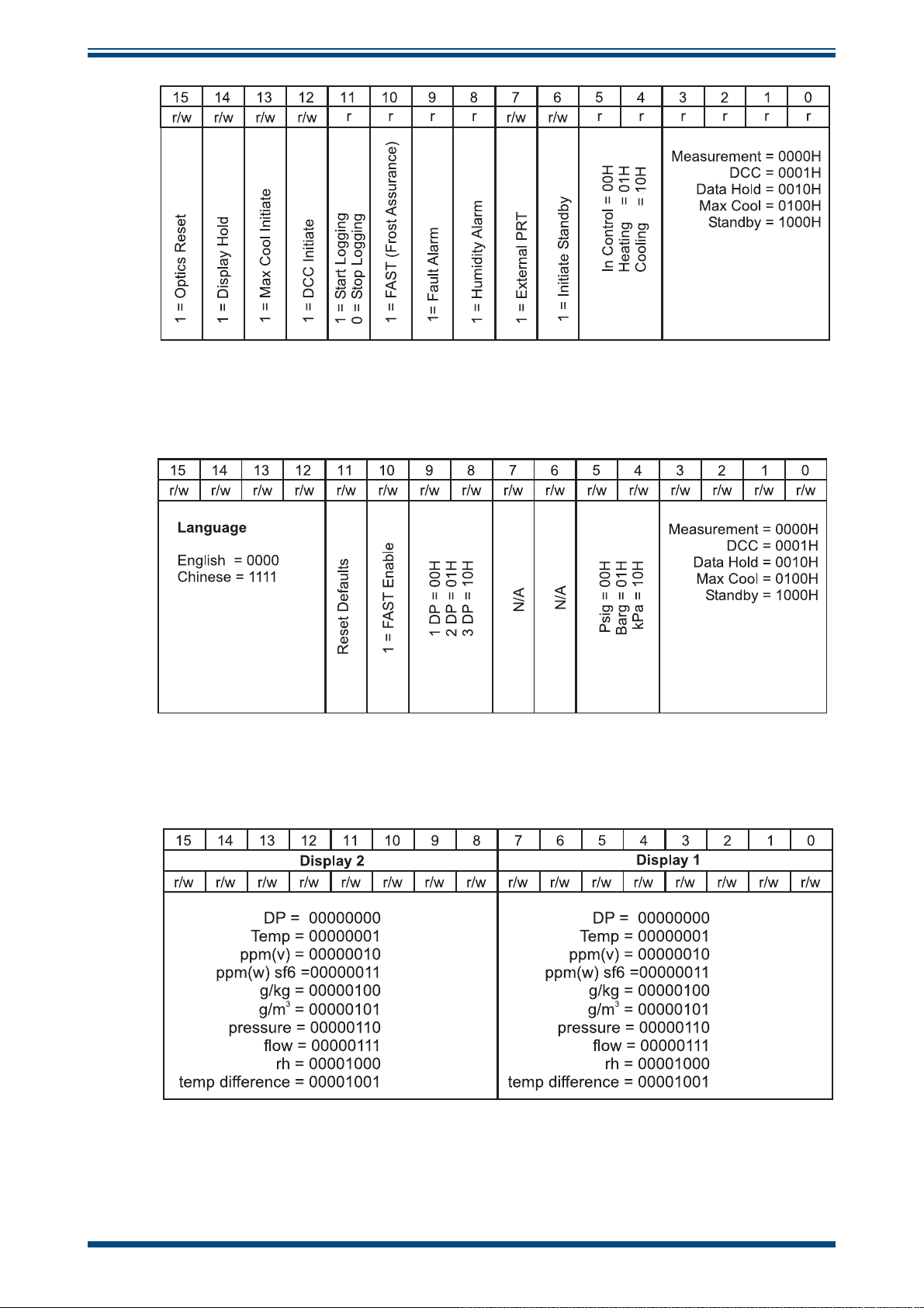
S8000 User’s Manual
Table 20 Register Confi guration D Status Word
APPENDIX D
Table 21 Register Confi guration E Units
Table 22 Register Confi guration F Display Setting A
Michell Instruments 71
Page 82

APPENDIX D
S8000 User’s Manual
Table 23 Register Confi guration F Display Setting B
Table 24 Register Confi guration H
Table 25 Register Confi guration J
Table 26 Register Confi guration K
72 97488 Issue 4, August 2018
Page 83

S8000 User’s Manual
APPENDIX D
Table 27 Register Confi guration L
Table 28 Register Confi guration M
The humidity values for sensors 1 & 2 are represented in IEEE-754 single precision
fl oating point format, in order to cater for the wide range in the value of ppm
format is ‘Big Ended’ which means that the high byte is at a lower address in memory
than the Lo byte, and is represented as such in the register memory map. The IEEE-754
format is shown below.
Table 29 Register Confi guration N
. This
V
Michell Instruments 73
Page 84

APPENDIX D
S8000 User’s Manual
Table 30 Register Confi guration P
74 97488 Issue 4, August 2018
Page 85

S8000 User’s Manual
APPENDIX E
Appendix E
Default Values
Michell Instruments 75
Page 86

APPENDIX E
Appendix E Default Values
The default values for the HMI Settings are as follows:
Main Page
Top Dew point
Middle ppm
Bottom g/m
Flow Fixed
Outputs
1 4-20 mA, dew point, -60 to +20 °C
2 4-20 mA, ppm
3 4-20 mA, fl ow, 0 to 1000 ml
V
3
, 0 to 3000
V
S8000 User’s Manual
Alarm 0°Cdp
Display
Resolution 2 decimal places
Primary Unit °C
Pressure unit bara
Stability 0:01
FAST ON
PRT Mode Internal
Language English
Brightness 100
DCC
Display Hold OFF
Period 0:02
Reset Optics reset
Set point Δ 20°C
Interval 4:00
Output Hold 0:20
Logging Interval 0:05
76 97488 Issue 4, August 2018
Page 87

S8000 User’s Manual
APPENDIX E
Appendix F
Quality, Recycling
& Warranty
Information
Michell Instruments 77
Page 88

APPENDIX E
S8000 User’s Manual
Appendix F Quality, Recycling & Warranty Information
Michell Instruments is dedicated to complying to all relevant legislation and directives. Full information
can be found on our website at:
www.michell.com/compliance
This page contains information on the following directives:
• ATEX Directive
• Calibration Facilities
• Confl ict Minerals
• FCC Statement
• Manufacturing Quality
• Modern Slavery Statement
• Pressure Equipment Directive
• REACH
• RoHS2
• WEEE2
• Recycling Policy
• Warranty and Returns
This information is also available in PDF format.
78 97488 Issue 4, August 2018
Page 89

S8000 User’s Manual
APPENDIX G
Appendix G
Return Document
&
Decontamination Declaration
Michell Instruments 79
Page 90

APPENDIX G
S8000 User’s Manual
Appendix G Return Document & Decontamination Declaration
'HFRQWDPLQDWLRQ&HUWL¿FDWH
IMPORTANT NOTE: Please complete this form prior to this instrument, or any components, leaving your
site and being returned to us, or, where applicable, prior to any work being carried out by a Michell
engineer at your site.
Instrument Serial Number
Warranty Repair? YES NO Original PO #
Company Name Contact Name
Address
Telephone # E-mail address
Reason for Return /Description of Fault:
Has this equipment been exposed (internally or externally) to any of the following?
Please circle (YES/NO) as applicable and provide details below
Biohazards YES NO
Biological agents YES NO
Hazardous chemicals YES NO
Radioactive substances YES NO
Other hazards YES NO
Please provide details of any hazardous materials used with this equipment as indicated above (use continuation sheet
if necessary)
Your method of cleaning/decontamination
Has the equipment been cleaned and decontaminated? YES NOT NECESSARY
Michell Instruments will not accept instruments that have been exposed to toxins, radio-activity or bio-hazardous
PDWHULDOV)RUPRVWDSSOLFDWLRQVLQYROYLQJVROYHQWVDFLGLFEDVLFÀDPPDEOHRUWR[LFJDVHVDVLPSOHSXUJHZLWKGU\
JDVGHZSRLQW&RYHUKRXUVVKRXOGEHVXI¿FLHQWWRGHFRQWDPLQDWHWKHXQLWSULRUWRUHWXUQ
Work will not be carried out on any unit that does not have a completed decontamination declaration.
Decontamination Declaration
I declare that the information above is true and complete to the best of my knowledge, and it is safe for Michell
personnel to service or repair the returned instrument.
Name (Print) Position
Signature Date
F0121, Issue 2, December 2011
80 97488 Issue 4, August 2018
Page 91
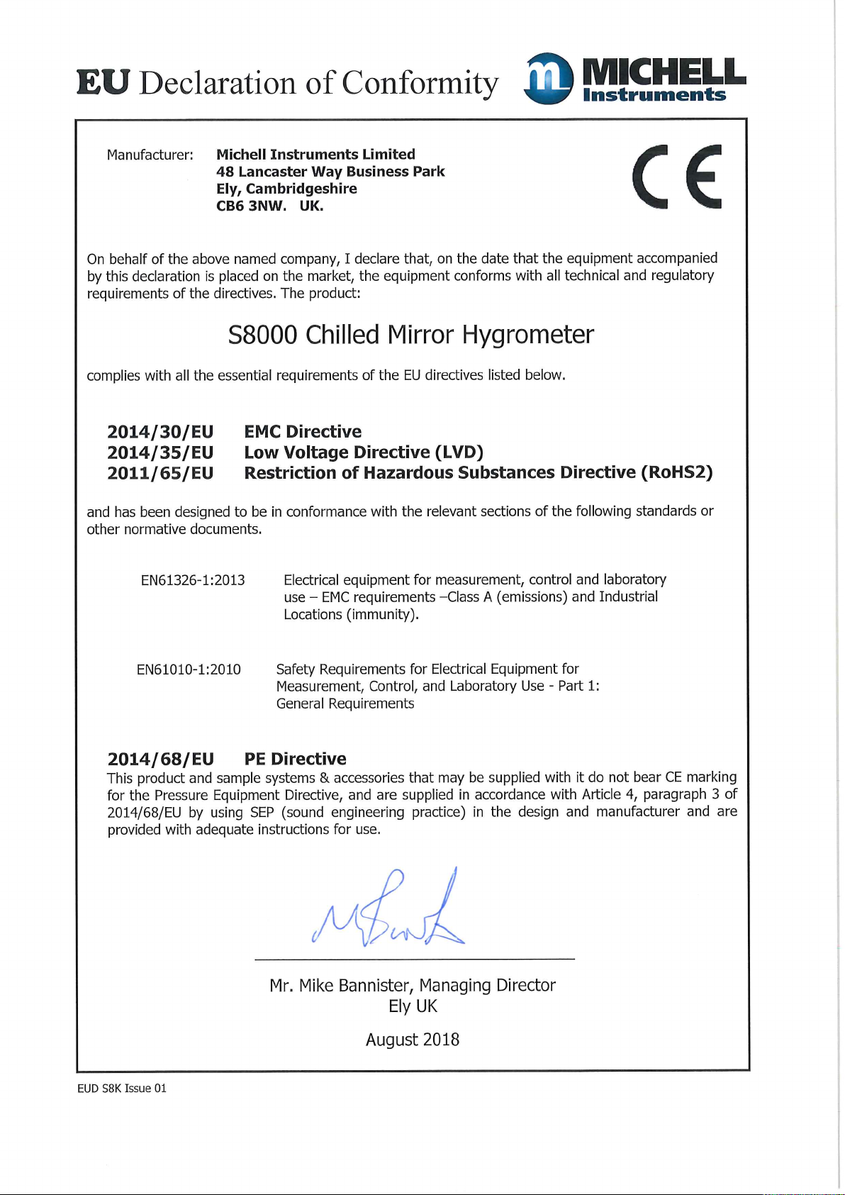
Page 92

http://www.michell.com
 Loading...