

Page 1

QMA601
Process Moisture Analyzer
User’s Manual
97449 Issue 3
June 2018
Page 2

Please fi ll out the form(s) below for each analyzer that has been purchased.
Use this information when contacting Michell Instruments for service purposes.
Analyzer
Code
Serial Number
Invoice Date
Location of Analyzer
Tag No
Analyzer
Code
Serial Number
Invoice Date
Location of Analyzer
Tag No
Analyzer
Code
Serial Number
Invoice Date
Location of Analyzer
Tag No
Page 3
QMA601
For Michell Instruments' contact information please go to
www.michell.com
© 2018 Michell Instruments
This document is the property of Michell Instruments Ltd. and may not be copied or
otherwise reproduced, communicated in any way to third parties, nor stored in any Data
Processing System without the express written authorization of Michell Instruments Ltd.
Page 4

QMA601 User’s Manual
Contents
Safety .............................................................................................................................. viii
Warnings ................................................................................................................... viii
Electrical Safety ......................................................................................................... viii
Pressure Safety .......................................................................................................... viii
Hazardous Materials (WEEE, RoHS2 & REACH) ............................................................. viii
Calibration (Factory Validation) ......................................................................................ix
Repair and Maintenance ...............................................................................................ix
Abbreviations ...................................................................................................................... x
1 INTRODUCTION ................................................................................................1
1.1 General .............................................................................................................. 1
1.2 Theory of Operation ........................................................................................... 2
1.3 Sample Gas Path ................................................................................................ 3
2 INSTALLATION ..................................................................................................4
2.1 Analyzer Storage Instructions .............................................................................. 4
2.2 Unpacking the Analyzer ...................................................................................... 5
2.3 Lifting and Handling ........................................................................................... 5
2.4 Mounting the Analyzer ........................................................................................ 6
2.5 Hazardous Area/Location Safety .......................................................................... 7
2.6 Electrical Safety .................................................................................................. 8
2.6.1 Equipment Ratings and Installation Details ...................................................... 8
2.6.2 Power Connection ....................................................................................... 10
2.6.3 Other Electrical Connections ........................................................................ 11
2.7 Pressure Safety ................................................................................................ 12
2.8 Gas Sample Connections ................................................................................... 13
3 OPERATION ....................................................................................................15
3.1 General Operational Information ........................................................................ 15
3.1.1 First Time Operation .................................................................................... 16
3.1.2 Analyzer Set-Up .......................................................................................... 17
3.2 User Interface .................................................................................................. 18
3.2.1 Interface Controls ....................................................................................... 18
3.2.2 ‘Up/Down Arrow’ Keys ................................................................................. 18
3.2.3 'ENTER’ Key ................................................................................................ 19
3.2.4 ‘ESC’ Key .................................................................................................... 19
3.2.5 Pop Up Keypad ........................................................................................... 19
3.3 Menu Structure ................................................................................................ 20
3.4 Description of Measured Parameters .................................................................. 21
3.5 Main Screen .................................................................................................... 21
3.5.1 Large Display Mode ..................................................................................... 23
3.6 Main Screen Sub Menus .................................................................................... 25
3.6.1 Warning Screen .......................................................................................... 25
3.6.2 Logging Screen ........................................................................................... 26
3.6.3 Alarm Screen .............................................................................................. 27
3.6.4 Field Calibration Screen ............................................................................... 28
3.6.5 Monitor screen ............................................................................................ 32
3.7 Settings Menu ................................................................................................. 33
3.7.1 Measurement Screen ................................................................................... 33
3.7.2 Outputs Screen ........................................................................................... 38
3.7.3 HMI Screen ................................................................................................ 40
3.7.4 Real Time Clock Screen ............................................................................... 42
3.7.5 Software Communications Screen................................................................. 43
3.7.6 Ethernet Screen .......................................................................................... 43
iv 97449 Issue 3, June 2018
Page 5

QMA601 User’s Manual
3.7.7 Field Calibration History ............................................................................... 44
3.7.8 About Screen .............................................................................................. 44
3.8 Sampling Guidelines ......................................................................................... 46
3.9 Measurement Cycle .......................................................................................... 49
3.10 Calibration Cycle ............................................................................................... 51
4 MAINTENANCE ................................................................................................53
4.1 Safety .............................................................................................................. 54
4.2 Removal and Replacement of the Power Supply Fuse .......................................... 54
4.3 Replacing the Optional Contamination Trap ........................................................ 54
4.4 Removal and Replacement of the Desiccant Column ............................................ 55
5 CALIBRATION ..................................................................................................57
5.1 Traceability ...................................................................................................... 57
6 SHIPPING .......................................................................................................59
6.1 Preparation for Shipping and Packing if Not Supplied as a Sample System ............ 59
7 APPLICATION SOFTWARE OVERVIEW ...............................................................60
7.1 System Requirements ....................................................................................... 60
7.2 System Connection ........................................................................................... 60
7.3 Getting Started ................................................................................................. 61
7.3.1 Connection Method (Serial Connection (RS485 or TCP) .................................. 62
7.3.1.1 RS485 Connection ................................................................................. 62
7.3.1.2 Modbus TCP Connection (Ethernet) ....................................................... 62
7.4 Main Window ................................................................................................... 63
7.5 Using the Chart ................................................................................................ 64
7.5.1 Chart Options Window ................................................................................. 65
7.6 Data Logging ................................................................................................... 66
7.6.1 Configuring Logging Start Time .................................................................... 67
7.6.2 Configuring Logging Stop Time .................................................................... 67
7.6.3 Starting the Log .......................................................................................... 67
7.6.4 Viewing a Log ............................................................................................. 67
7.7 Parameters / Field Calibration ............................................................................ 67
7.7.1 Field Calibration .......................................................................................... 68
Michell Instruments v
Page 6

QMA601 User’s Manual
Figures
Figure 1 Measurement System .................................................................................3
Figure 2 Mounting Dimensions .................................................................................6
Figure 3 Earthing Stud And Nut Washer Assembly .....................................................9
Figure 4 24 VDC & 240 V AC Power Unit Connectors ................................................10
Figure 5 Other Electrical Connections ......................................................................11
Figure 6 RJ45 to screw terminal adapter connections ...............................................12
Figure 7 Typical Display .........................................................................................17
Figure 8 User Interface ..........................................................................................18
Figure 9 Up/Down Arrow Keys ................................................................................18
Figure 10 ‘ENTER’ Key .............................................................................................19
Figure 11 ‘ESC’ Key .................................................................................................19
Figure 12 Pop Up Keypad .........................................................................................19
Figure 13 Menu Structure ........................................................................................20
Figure 14 Main Screen .............................................................................................21
Figure 15 Large Display Modes .................................................................................23
Figure 16 Full Screen Graph .....................................................................................24
Figure 17 Warning Screen ........................................................................................25
Figure 18 Logging Screen ........................................................................................26
Figure 19 Alarm Screen ...........................................................................................27
Figure 21 Field Calibration Screen 2 ..........................................................................30
Figure 22 Field Calibration Screen 3 ..........................................................................30
Figure 23 Field Calibration Screen 4 ..........................................................................31
Figure 24 Field Calibration Screen 5 ..........................................................................31
Figure 25 Monitor Screen .........................................................................................32
Figure 26 Settings Menu Screen ...............................................................................33
Figure 27 Measurement Screen ................................................................................34
Figure 28 Carrier Gas Screen ....................................................................................35
Figure 29 Measurement Screen ................................................................................36
Figure 30 External Options .......................................................................................37
Figure 31 Fixed Options ...........................................................................................37
Figure 32 Atmos. Option ..........................................................................................37
Figure 33 User Gas Setup Screen .............................................................................38
Figure 34 Outputs Screen ........................................................................................39
Figure 35 HMI Screen ..............................................................................................40
Figure 36 Real Time Clock Screen .............................................................................42
Figure 37 Software Communications Screen ..............................................................43
Figure 38 Ethernet Screen .......................................................................................43
Figure 39 Calibration History Screen .........................................................................44
Figure 40 About Screen ........................................................................................... 45
Figure 42 Measurement Cycle (Phase 2) Calibration Flow ...........................................50
Figure 43 Calibration Cycle (Phase 1) - Dried Sample Flow .........................................51
Figure 44 Calibration Cycle (Phase 2) - Sample Flow ..................................................52
Figure 45 Typical QMA601 Calibration Certificate .......................................................58
vi 97449 Issue 3, June 2018
Page 7

QMA601 User’s Manual
Tables
Table 1 Pop Up Keypad ..........................................................................................20
Table 2 Main Screen Parameters ............................................................................. 23
Table 3 Large Parameter Display Mode ................................................................... 24
Table 4 Warning Screen ......................................................................................... 27
Table 5 Logging Screen .........................................................................................27
Table 6 Alarm Screen Parameters .......................................................................... 28
Table 7 Calibration Screen Parameters .................................................................... 30
Table 8 Monitor Screen Parameters ....................................................................... 33
Table 9 Measurement Screen ................................................................................. 35
Table 10 Outputs Screen Parameters ....................................................................... 40
Table 11 HMI Setup Screen Parameters ................................................................... 42
Table 12 Real Time Clock Screen Parameters ........................................................... 43
Table 13 Software Communications Screen Parameters..............................................44
Table 15 Calibration History Screen .......................................................................... 45
Table 14 Ethernet Screen Parameters ....................................................................... 45
Table 16 Using the Chart ......................................................................................... 65
Table 17 Chart Options ............................................................................................ 66
Table 18 Modbus Register Map ................................................................................ 83
Appendices
Appendix A Technical Specifi cation ............................................................................... 71
Appendix B Hazardous Area Certifi cation ...................................................................... 74
B.1 Product Standards ....................................................................... 74
B.2 Product Certifi cation .................................................................... 74
B.3 Global Certifi cates/Approvals ........................................................74
B.4 Special Conditions of Use ............................................................. 74
B.5 Maintenance and Installation ........................................................ 75
Appendix C Modbus Holding Register Map ....................................................................77
C.1 Set Points and Ranges ................................................................. 93
C.2 Gases for Gas Correction Values ...................................................94
Appendix D Quality, Recycling, Compliance & Warranty Information ................................ 96
Appendix E Return Document & Decontamination Declaration ........................................ 98
Appendix F Calculating Conversion Factors for Gas Mixes ............................................. 100
Michell Instruments vii
Page 8
QMA601 User’s Manual
!
DANGER
Electric
Shock Risk
Safety
The analyzer is designed to be completely safe when installed and operated correctly in accordance
with the information provided in this manual.
This manual contains all the required information to install, operate and maintain this product. Prior
to installation and use of this product, this entire manual should be read and understood. Installation
and operation of this product should be carried out by suitably competent personnel only. The
installation and operation of this product must be in accordance with the instructions provided and
according to the terms of any associated safety certificates. Incorrect installation and use of this
product other than those described in this manual and other than its intended purpose will render
all warranties void.
This product meets the essential protection requirements of the relevant EU directives. Further
details of applied directives may be found in the product specification.
Electricity and pressurized gas can be dangerous. This product must be installed and operated only
by suitable trained personnel.
Warnings
Where this hazard warning symbol appears in the following sections,
it is used to indicate areas where potentially hazardous operations
need to be carried out and where particular attention to personal and
personnel safety must be observed.
Where this symbol appears in the following sections it is used to
indicate areas of potential risk of electric shock.
Electrical Safety
Ensure electrical safety is complied with by following the directions provided here and observing all
local operation & installation requirements at the intended location of use.
This product is completely safe when using any options and accessories supplied by the manufacturer
of this product for use with it. Refer to Section 2 (Installation) of this manual for further details.
Pressure Safety
For this product to operate satisfactorily, pressurized gas must be connected to it. Observe all the
information contained within this manual and all local operation & installation requirements at the
intended location of use. Refer to Section 2 (Installation) of this manual for further details.
Hazardous Materials (WEEE, RoHS2 & REACH)
This product does not contain or release any prohibited chemicals listed on the SVHC (Substances
of Very High Concern) Candidate List. During the intended normal operation of this product it is not
possible for the user to come into contact with any hazardous materials. This product is designed to
be recyclable except where indicated, see relevant sections in this manual for further details.
viii 97449 Issue 3, June 2018
Page 9

QMA601 User’s Manual
Calibration (Factory Validation)
Prior to shipment, the analyzer undergoes stringent factory calibration to traceable standards. Due
to the inherent stability of the analyzer, regular factory calibration is not required under normal
operating conditions. The analyzer should perform reliably for many years with just basic maintenance,
housekeeping and regular field calibrations from the internal reference (moisture generator) or a
known external reference.
There are, however some consumables that will require periodic replacement.
• Moisture generator - typical lifetime of around 3 years.
• Desiccant column - typical lifetime of around 1 year, but this strongly
depends on the moisture content of the sample gas. The drier the sample
gas, the longer lifetime of the desiccant.
• Optional contamination trap - typical lifetime of around 1 year, a
column of activated charcoal that protects the Desiccant Column from
contamination in applications where the process gas composition contains
heavy hydrocarbon vapors.
Michell Instruments can provide a fully traceable factory calibration service for the analyzer and it is
recommended that this is considered at intervals of every year of the analyzer's life. Please contact
your local Michell Instruments' office or representative for further details (www.michell.com).
Repair and Maintenance
Apart from user-replaceable components required for routine operational maintenance described
above, the analyzer must only be maintained either by the manufacturer or an accredited service
agent. Refer to www.michell.com for details of Michell Instruments’ worldwide offices contact
information.
Michell Instruments ix
Page 10

Abbreviations
The following abbreviations are used in this manual:
AC alternating current
atm pressure unit (atmosphere)
barg pressure unit (=100 kP or 0.987 atm) gauge
°C degrees Celsius
°F degrees Fahrenheit
EU European Union
Hz Hertz
IEC International Electrotechnical Commission
kg kilogram
lb pound
lbs/MMscf pounds per million standard cubic foot
mA milliampere
mV millivolt(s)
mbar millibar
ml/min milliliters per minute
ppm
parts per million (by weight)
W
ppm
parts per million (by volume)
V
psig pound(s) per square inch (gauge)
RH relative humidity
RTU Remote Terminal Unit
V Volts
W Watts
" Inch
QMA601 User’s Manual
x 97449 Issue 3, June 2018
Page 11

QMA601 User’s Manual
1 INTRODUCTION
1.1 General
The QMA601 Moisture Analyzer is designed to provide reliable, fast and accurate
measurement of trace moisture content in a wide variety of process applications where
keeping moisture levels as low as possible is of critical importance.
The high-contrast capacitive button operated LCD display presents all measured data
to the user in a clear and understandable format. The main display incorporates a realtime trend graph and alarm indicators based on the NAMUR 102 standard. A powerful
and intuitive HMI makes control, logging and configuration of analyzer parameters easy.
The analyzer provides two user-configurable analog outputs, and Modbus RTU/TCP
communications, allowing it to interface with a SCADA DCS system, or by a computer
using the dedicated application software. A set of 4 adjustable volt free alarm contacts
allow the QMA601 to be used for direct process control.
Use Your Preferred Communication Media
INTRODUCTION
For greater flexibility, the QMA601 offers:
• Modbus RTU/TCP
• 2 user-configurable analog outputs
• Status and Process Alarms
Minimal & Straightforward Maintenance
Sophisticated analyzers are often complicated and require experience and special care
in use, increasing cost of ownership. The QMA601 differs through its very uncomplicated
approach to field service; the Desiccant Column is easy to replace via its mounting on
the sampling panel. The moisture generator has an average life span of 3 years after
which it can simply be replaced with a calibrated moisture generator supplied by Michell
Instruments.
Automated Calibration for Continued Reliability
The QMA601 incorporates an integrated automatic calibration system for complete
user confidence. Periodic calibration checks of sensor performance can be initiated
on demand, or automatically (at user defined intervals and time of day), providing a
verification of analyzer performance and automatically adjusting out any change. The
moisture generator at the core of this system is supplied with a calibration traceable to
NPL and NIST, but an external calibration reference source can also be used if desired.
During a calibration cycle, the Data Hold function will prevent any interruption of
dependant processes by holding the analog outputs at the same level for the duration
of the calibration.
Michell Instruments 1
Page 12

INTRODUCTION
Full Hazardous Area Certification
The analyzer is ATEX, IECEx and cCSAus certified. The main unit (electronics and
sensing) and associated sampling system may be mounted at a convenient location
next to the pipeline or process, with gas sample and vent connections. The analyzer
is supplied in either a 85-264 V AC version or a 24 V DC version. The product serial
number label will identify the required operating power supply.
Purpose Designed Sample Systems
Sample extraction, handling and conditioning techniques are of critical importance to
assure optimal performance and reliability of all gas analyzers which accurately quantify
specific components within a process gas composition. Three sample systems have
been designed for the most common process moisture analyzer applications:
• Natural Gas Glycol Dehydration & Transmission with an advanced
membrane filter to combat liquid contamination.
• Trace Moisture in High Purity & Petrochemical Gases with protection
against particulates.
QMA601 User’s Manual
• Trace moisture for Asymmetric Cycle variant, includes membrane filter
and 3 way valve for purge gas.
Our QMA601 sample systems facilitate regulation of pressure and flow, and the removal
of contaminants, delivering a properly conditioned sample to the analyzer for reliable
measurements, and trouble-free operation. The integrated bypass system increases
transport speed of the sample while reducing gas wastage. Each high quality sample
system is constructed from 316 stainless steel components, with BS EN 10204 3.1
material certificates available on request.
1.2 Theory of Operation
A pair of frequency-matched quartz crystal oscillators are used for measurement and
are both exposed to the sample gas. The measurement crystal features a hygroscopic
coating to adsorb moisture, whereas the reference crystal is uncoated. As the hygroscopic
coating on the measurement crystal adsorbs moisture from the sample, the overall mass
of the crystal is increased, modifying the oscillation frequency in a precise, repeatable
and measurable manner.
The resulting measurement is highly accurate, and insensitive to changes in background
gas composition.
2 97449 Issue 3, June 2018
Page 13
QMA601 User’s Manual
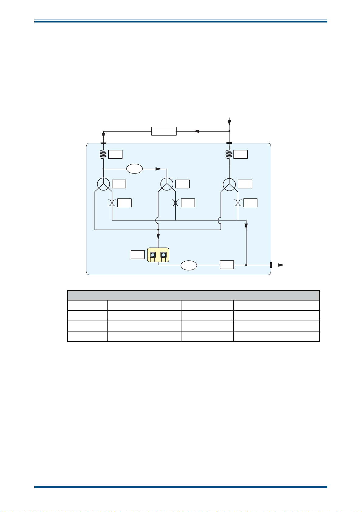
1.3 Sample Gas Path
The QMA601 measurement system must be supplied with gas at the required pressure
(to match that of its calibration) via the 1/4'' female NPT gas inlet on the flame arrestor.
The flow is controlled automatically.
The sensor cell is located at the end of the sensor block and contains the sensor and
reference oscillators.
Figure 1
HE1 HE2
V1 V2 V3
MG
INTRODUCTION
shows a schematic diagram of this sampling system.
SAMPLE
IN
DD
DD
MFC
QCH
PS
FC1 FC2 FC3
QCH
PS
MFC
Key
Desiccant column
Mass flow controller
Sensor cell
Pressure sensor
Figure 1
MG
V1, V2, V3
HE1, HE2
FC1, FC2, FC3
Measurement System
SAMPLE
Moisture generator
Solenoid valves
Heat exchanger
Flow control
OUT
Michell Instruments 3
Page 14

INSTALLATION
2 INSTALLATION
2.1 Analyzer Storage Instructions
In order for this product to be functional upon installation it should be stored in
accordance with the guidelines below:
• The product must be housed in a sheltered area, out of direct sunlight
and rain.
• The product should be stored to minimize the possibility of sitting in
ground water.
• The temperature within the storage environment should be maintained
between -20 to +60°C (-4 to +140°F).
• The humidity within the storage environment must be non-condensing.
• The storage environment must not expose the analyzer to any corrosive
elements.
QMA601 User’s Manual
• The product should stay assembled with its sample conditioning system
(if supplied).
• All electrical and process connections should remain disconnected and
capped.
• All protective coatings should remain in place until installation.
• For prolonged periods of storage, the lid of the packaging crate should be
removed to allow air to circulate.
• Any documentation supplied with the product should be removed from
the packaging crate and stored elsewhere to protect its integrity.
For the period from installation of the product to commissioning start-up, the following
precautions should be followed:
• The product and associated sampling system (if supplied) must remain
isolated from the process gas, and the enclosure should remain closed to
ensure ingress protection is maintained.
• If supplied, the sampling system enclosure heating/thermostat circuit
should be operated if the climatic temperature might fall below +5°C
(+41°F).
• At time of start-up the procedures contained in the user manuals for both
analyzer and sampling system must be followed.
If the product was previously in service/operation then the following precautions should
be followed before storage:
• Upon isolation from the gas sample the entire system should be purged
with a dry nitrogen gas before powering down of the analyzer.
• All connections and ports (gas and electrical) to the analyzer or sample
system (if provided) should be capped.
• If the product is not removed from its location, the electrical grounding of
the analyzer should remain in place.
4 97449 Issue 3, June 2018
Page 15
QMA601 User’s Manual
!
!
2.2 Unpacking the Analyzer
Open the crate and carefully unpack the analyzer.
The accessories box should contain the following items:
• Traceable calibration certificate
• Application software CD
• Users manual
INSTALLATION
WARNING:
The analyzer weighs 35kg (77lbs) alone,
or 50kg (110lbs) in the crate
If there are any shortages please notify the supplier immediately.
NOTE: Retain the packaging in case the analyzer is returned for factory
calibration or service.
2.3 Lifting and Handling
The QMA601 is not designed as portable or transportable equipment. The product
should be rigidly fixed in position as per the full installation instructions.
The weight of the analyzer is 35kg (77lbs). Therefore, appropriate lifting and handling
techniques should be used during the installation process. Before commencing any lifting
or handling ensure that its intended location is suitable and appropriately prepared.
Make sure that mounting point design considerations have employed locally approved
safety factors.
WARNING:
Personnel must observe suitable lifting and handling
precautions.
When handling and installing this analyzer (particularly after removal from its packaging)
ensure that it is not dropped, impacted or subjected to high levels of vibration or
environmental conditions that may impair its operation.
Michell Instruments 5
Page 16
INSTALLATION
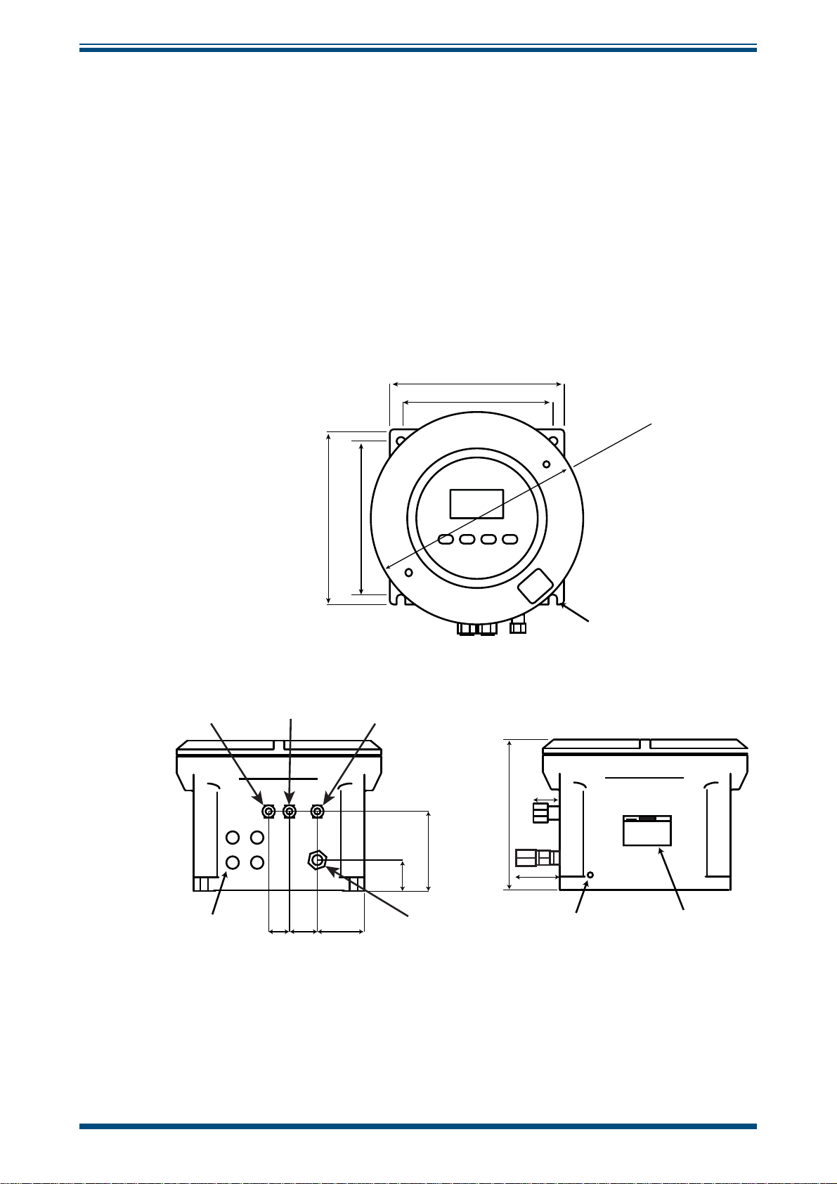
2.4 Mounting the Analyzer
The analyzer is housed in an aluminum Exd enclosure suitable for wall or panel
mounting. Four mounting points are available with M10 clearance holes on fixing
centers of X = 308mm and Y = 312mm.
The enclosure provides environmental ingress protection IP66/NEMA4 and should be
mounted vertically in a location free of any appreciable vibration. It should be placed in
a shaded position to prevent heating effects through sun radiation. The weight of the
analyzer is 35kg (77lbs).
Conduit entries are intended for connection to threaded rigid metal conduit or other
wiring methods in accordance with Article 501 of the National Electrical Code ANSI/
NFPA 70-2005.
335mm
(13.2”)
QMA601 User’s Manual
308mm
(12.1”)
Desiccant
Column
Outlet
335mm
(13.2”)
312mm
Sample In
(12.3”)
TOP VIEW
280mm
131mm
(5.2”)
41mm
(11.0”)
(1.6”)
410mm
Ø
16
(
4 off M10
”)
14
.
66mm
(2.6”)
External Earth Point Marking Label
4 off M20
threaded entries
41mm
(1.6”)
50mm
(2.0”)
97mm
(3.8”)
57mm
(2.2”)
Enclosure
Breather
(do not obstruct)
FRONT VIEW RIGHT VIEW
Figure 2
6 97449 Issue 3, June 2018
Mounting Dimensions
Page 17
QMA601 User’s Manual
!
2.5 Hazardous Area/Location Safety
This product is compliant for installation and use in a Hazardous Area/Location. All
certificates awarded to this product should be fully examined prior to installation and
use.
This product is certified safe for use in an ATEX Zone 1 and
Zone 2 / Class I, Division 1 area only. This product must not
be installed or used within a Zone 0 area.
This product must not be operated within an explosive
atmosphere greater than 1.1 bara (16 psia).
INSTALLATION
WARNING:
WARNING:
WARNING:
This product must not be operated with enriched oxygen
atmospheres (more than 21% oxygen content).
WARNING:
This product must not be operated outside of the
temperature range of +5 to +45°C (+41 to +113°F)
Refer to Appendix B for the Hazardous Area/Location certification details of this product.
Hazardous Area/Location certificates for this product may be downloaded from:
http://www.michell.com.
This product is fitted with a marking label that contains Hazardous Area/Location
information pertinent to the suitable location and installation.
During all installation and operation activities, local regulations and permitted working
routines must be observed. Installation should only be performed by competent
personnel and, where applicable, in accordance with IEC/EN 60079-14:2008 or local
equivalents.
Cable glands/barrier glands/conduit seals shall be installed in accordance with the
manufacturer’s instructions.
Repair and servicing of this equipment must only be carried out by the manufacturer. An
Installation and Maintenance Information Sheet is supplied separately to the manual.
Michell Instruments 7
Page 18

INSTALLATION
DANGER
Electric
Shock Risk
2.6 Electrical Safety
QMA601 User’s Manual
WARNING:
During the installation of this product ensure that all
applicable national and local electrical safety regulations
are observed.
WARNING:
Isolate the power prior to installation.
WARNING:
Always ensure that power is switched off prior to accessing
the product for any purpose other than normal operation, or
prior to disconnecting any cables.
Fuse
This product is provided with an internally mounted fuse located beneath the power
connector.
The fuses are rated at 5 x 20mm anti-surge to IEC60127-2:
Mains 240 V AC 3 A
24 V DC 6.3 A
A replacement fuse can be obtained by contacting Michell Instruments' technical support.
2.6.1 Equipment Ratings and Installation Details
This equipment and all power isolation devices must be installed in a location and
position that allows safe and easy access to their operation and is able to rigidly support
the equipment.
For location and mounting arrangements - refer to the relevant sections of this manual
for further details.
Do not install this equipment in a location that would expose it to impact or high levels
of vibration. Installation of this equipment must include the provision of a suitable and
locally positioned power isolation switch or circuit breaker. Indication of the purpose
of the switch or circuit breaker is strongly recommended. An over-current protection
device should be rated to a maximum of 10 A. Ensure that the power supply is sufficient
to satisfy the instrument's power consumption requirements.
Any power supply terminals and voltages must be suitably separated from the other
input/output requirements of this product.
8 97449 Issue 3, June 2018
Page 19

QMA601 User’s Manual
The product enclosure is supplied with an external protective earthing/grounding
terminal at the lower right hand side as shown in the figure below. As the first step
of the electrical installation - connect this earthing/grounding terminal to plant earth/
ground by a minimum 4mm
comprises of an earth bolt, 2 x plain washers and 1 x spring washer, which are all nickel
plated.
INSTALLATION
2
earth/ground bond strap. The earthing/grounding terminal
Figure 3
Mains Powered Units
As a minimum, the power connection cable should be 3 core over sleeved,
with minimum 0.5mm insulation and rated at 300 V. Cables should have
Live (L), Neutral (N) and Earth [Ground] (E) conductors.
Ensure suitably rated power supply cables and glands are used to ensure that
electrical safety is maintained. Connect each of the Live (L), Neutral (N) and
Earth [Ground] (E) conductors to the similarly marked terminals (L, N, E) on
the Power In connector shown above.
24 V DC Units
The cable should be rated at a minimum of 10 A at 50 V DC with minimum
0.5mm insulation. Connect the +24 V conductor to the terminal marked +
and the 0 V conductor to the terminal marked -.
Before applying power, perform a continuity test to ensure that the power supply cable
and product are effectively connected to the protective earth. A protective earth terminal
is mounted internally and the Earth wire connected to it should never be disconnected.
Earth Bolt And Nut Washer Assembly
Do not remove or exchange any of the cables, electrical components or any other parts
supplied with this product. Doing so will invalidate all warranties.
If installing rigid conduit, a stopping fitting must be installed within 46cm (18") of the
enclosure.
There are no additional or special electrical safety requirements other than those
referred to in this manual.
Michell Instruments 9
Page 20
INSTALLATION
DANGER
Electric
Shock Risk
This product is designed to be safe under the following conditions: between a
temperature range of -40 to +60°C (-40 to +148°F), in maximum 80% relative humidity
for temperatures up to +31°C (+88°F) decreasing linearly to 50% RH at +50°C
(+122°F). Supply voltages of ±10% and transient over voltages up to Overvoltage
Category II. Pollution Degree 2. Altitudes up to 2000m. Outdoor mounting is permitted
using suitably rated glands equivalent to NEMA 4 / IP66. See Appendix A, Technical
Specification, for full operating parameters.
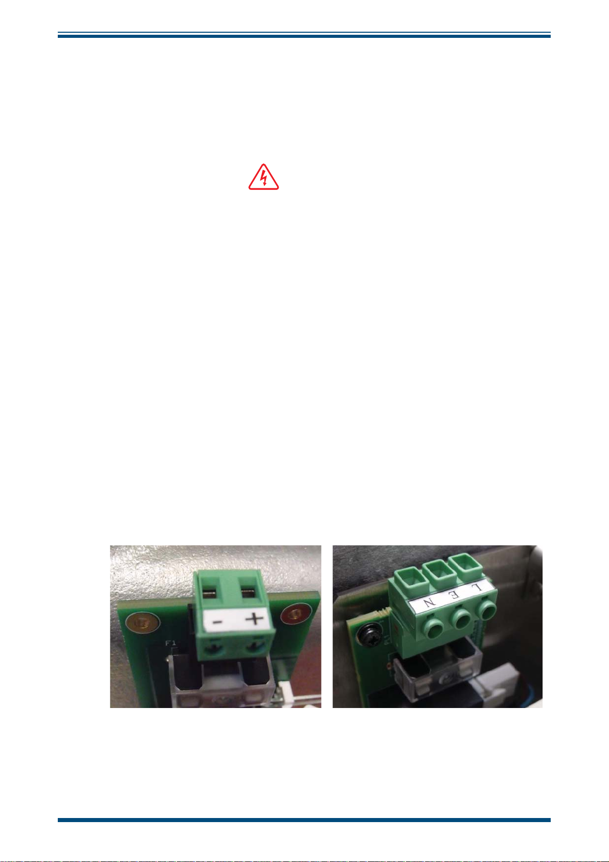
2.6.2 Power Connection
The product is provided with 4 x M20 threaded cable gland entries for customer
connection. Only these gland entry points may be used. The end user/installer is not
permitted to machine additional entries into the enclosure.
This equipment must be supplied with a voltage between the range of 85 to 264 V AC,
47/63 Hz (140 W max) or 24 V DC (140 W max) to function correctly. Cable entry into
the measurement system is made through the bottom of the enclosure.
QMA601 User’s Manual
For an 85/264 V AC powered unit the terminals are marked:
L Live (= IEC Brown)
N Neutral (= IEC Blue)
E Earth/Ground (= IEC Green/Yellow)
For a 24 V DC powered unit, the terminals are marked:
+ 24 V DC
- 0 V DC
All power connections are made via a removable screw terminal connector mounted on
the mains connection PCB shown in
Figure 4.
Figure 4
24 V DC & 240 V AC Power Unit Connectors
All input and output connectors are 2-part pcb mounted type rated @ 300 V 10 A. The
detachable, screw terminal half of each connector is designed to accept 0.5 to 2.5mm2 (24
-12 AWG) stranded or solid conductors. The connector 2-pin for 24 V DC and 3-pin for 240
V AC.
10 97449 Issue 3, June 2018
Page 21

QMA601 User’s Manual
2.6.3 Other Electrical Connections
The power supply (shown below as a silver box) will not be in the 24 V DC version.
INSTALLATION
Figure 5
1 Analog Outputs
21 OP220 OP2+
19 OP118 OP1+
2 External Pressure
17 –
16 +
3 Alarms 3-4
15 COM4 Analyzer Status Alarm
14 NO4
13 NC4
12 COM3
11 NO3
10 NC3
Other Electrical Connections
NO in warning/fault condition
NC no warning/ no fault
4 Alarms 1-2
9 COM2
8 NO2
7 NC2
6 COM1
5 NO1
4 NC1
5 RS485
3G
2B
1A
Michell Instruments 11
Page 22
INSTALLATION
!
!
QMA601 User’s Manual
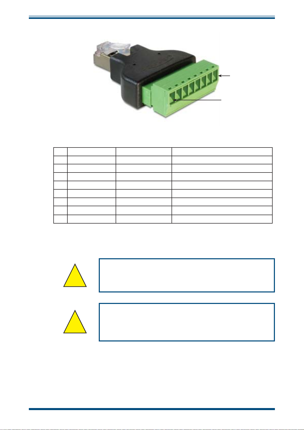
Pin 1
Pin 8
Figure 6
Pin Signal Name Description Cable Wire Color
1 TX+_D1 Transmit Data+ White with orange stripe
2 TX-_D1 Transmit Data- Orange with white stripe or solid orange
3 RX+_D2 Receive Data+ White with green stripe
4 BI+_D3 Bi-directional+ Blue with white stripe or solid blue
5 BI-_D3 Bi-directional- White with blue stripe
6 RX-_D2 Receive Data- Green with white stripe or solid green
7 BI+_D4 Bi-directional+ White with brown stripe
8 BI-_D4 Bi-directional- Brown with white stripe or solid brown
2.7 Pressure Safety
RJ45 to screw terminal adapter connections
WARNING:
This product is used in conjunction with pressurized gases.
Observe pressurized gas handling precautions.
WARNING:
Pressurized gas is dangerous and should only be handled by
suitably trained personnel.
DO NOT permit pressures greater than the specified safe working pressure to be applied
directly to the analyzer.
12 97449 Issue 3, June 2018
Page 23
QMA601 User’s Manual
!
!
Unless otherwise specified the QMA601 is calibrated at
a sample pressure of 3 barg (43.5 psig) on the gas inlet,
and a back-pressure of 2 barg (29 psig) on the outlet.
Operating the analyzer at a different pressure invalidates
Similarly, gas pressure affects the output of the internal
moisture generator, thereby invalidating further auto
calibrations which use a built-in moisture generator as a
2.8 Gas Sample Connections
The following points should be considered when installing the sample gas supply line:
• PTFE tape is recommended for pipe connections.
• Solvent based pipe thread sealant should not be used, as condensable
components or contaminates can be leached during the curing period.
INSTALLATION
the calibration.
reference.
Care and attention to the position and installation of the tubing will minimize problems
caused by avoidable contamination. The most common issue with of sample flow is the
accumulation of liquid in impulse lines during a shutdown period. If the measurement
system has not been isolated, condensate can be displaced, on re-start, into components
and associated tubework.
WARNING:
Exd enclosure breather must remain open to atmosphere at
all times, without any obstruction - See Figure 2.
Michell Instruments' recommendations are:
• The sampling point from the process line should be taken from the
top of the process line. If a radial probe is used the orifice should face
downstream.
• It is recommended that Viton is used for all O-rings.
• The internal volume of the impulse tubing connecting between the process
line and this product should be as small as possible to minimize response
lag time to changing process conditions.
• Piping should be lagged and/or trace heated if ambient temperatures
could cause the sample gas to fall below its dew-point temperature.
• A drain valve should be placed at the lowest point in the system.
• It should be standard procedure to isolate this product during shutdowns
or when plant problems are being experienced and to adequately purge
the supply lines before restarting.
• The relatively large area of surfaces and internal volume of inline
components can be particularly troublesome if contamination is
experienced.
Michell Instruments 13
Page 24

INSTALLATION
Prolonged purging, or stripping and cleaning, followed by re-purging with
gas may be necessary to remove the contamination.
• Avoid sample gas streams that are already very close to the dew point
or which have dispersed liquid within them. In such cases, sampling
from fast loops and/or from downstream of existing catch pot/coalesce
systems is always preferred.
Failure to observe these recommendations will potentially cause problems of
contamination as well as causing consequential inaccurate, unreliable and inconsistent
monitoring. If a top-entry sample point is not available, extra attention should be given
to the design of the sample line installation to avoid unwanted contamination.
QMA601 User’s Manual
14 97449 Issue 3, June 2018
Page 25

QMA601 User’s Manual
3 OPERATION
This section describes both the general operation of the analyzer and the method of
setting-up and changing the default parameters should this become necessary.
NOTE: Before operating the analyzer read Sections 1 to 3 which explain the
analyzer’s functionality, installation, controls, display functions and screens.
Prior to operation, the analyzer must have been connected to the correct electrical
power supply and the relevant analog and alarm outputs connected to external systems
as required and as described in Section 2. The analyzer must also have been installed
as detailed in Section 2 and connected to a sample gas supply that is representative of
the monitored process.
3.1 General Operational Information
OPERATION
Operation of the QMA601 is completely automated and once set-up requires little or no
operator intervention.
Michell Instruments 15
Page 26

OPERATION
3.1.1 First Time Operation
To commence operation, proceed as follows:
1. Connect the sampling line to the sample system. It is recommended to
heat trace the sample gas line.
2. Switch on the power supply to the analyzer. The Initializing Screen will
appear.
QMA601 User’s Manual
QMA601
Process Moisture Analyzer
Initializing
3. After the initializing period has finished, the following display will appear.
Oven heating to set point, please wait!
Skip
1
2
3
4
4. This heating period lasts about an hour allowing time for the internal
sampling system to be purged with the sample gas.
16 97449 Issue 3, June 2018
Page 27
QMA601 User’s Manual
!
3.1.2 Analyzer Set-Up
During the period when the oven is heating to set point, all functions, except for HMI
adjustments, are disabled until the oven has reached its operating temperature. Press
the
ENTER key to enter the HMI Screen (see Section 3.73) to set up the temperature
and pressure units before operating the analyzer for the first time. Note: Pressing the
ENTER key only takes you to the HMI screen when the oven heating message with
"skip" button is present.
OPERATION
Parameter
1 & 2
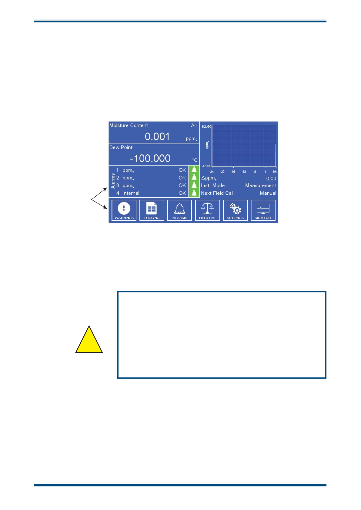
Figure 7
Using the inlet pressure regulator adjust the sample pressure until the reading on the
internal sensor pressure readout matches the value on the calibration certificate. The
back-pressure should also be adjusted to the value shown on the calibration certificate.
Unless otherwise specified the QMA601 is calibrated at
a sample pressure of 3 barg (43.5 psig) on the gas inlet,
and a back-pressure of 2 barg (29 psig) on the outlet.
Operating the analyzer at a different pressure invalidates
Similarly, gas pressure affects the output of the internal
moisture generator, thereby invalidating further auto
calibrations which use a built-in moisture generator as a
Typical Display
the calibration.
reference.
Michell Instruments 17
Page 28

OPERATION
3.2 User Interface
The QMA601 features a 7” color display.
3.2.1 Interface Controls
QMA601 User’s Manual
Four capacitive touch keys are used to navigate the menu system.
Key presses are detected through the glass front panel, and are indicated by a blue LED
above the key.
3.2.2 ‘Up/Down Arrow’ Keys
Up () and Down () keys are used to move to required menu items. The
The
selected menu item is surrounded by a black frame.
Figure 8
Figure 9
User Interface
Up/Down Arrow Keys
Numerical options activate a pop up keypad. For more information on the keypad see
Section 3.2.5.
18 97449 Issue 3, June 2018
Page 29

QMA601 User’s Manual
3.2.3 'ENTER’ Key
OPERATION
ENTER
The ENTER key is used to navigate into menus, open keypads, cycle through options,
and accept changes.
For non-data entry options pressing the
3.2.4 ‘ESC’ Key
The ESC key is used to return to the previous menu and is also used to leave keypads
without accepting any changes.
Figure 10
Figure 11
‘ENTER’ Key
ENTER key moves to the next available option.
ESC
‘ESC’ Key
Michell Instruments 19
Page 30

OPERATION
3.2.5 Pop Up Keypad
Allows the user to enter numerical data. The figures below the box indicate the minimum
and maximum limits which can be entered.
QMA601 User’s Manual
000.0
0.0 to 300.0
Figure 12
Key Action Note
ESC
Up () and Down ()
ENTER
Moves cursor to last digit.
Exits to previous page.
Increments or decrements
selected number.
Moves cursor to next digit.
If at last digit, and within
allowable range, updates
value.
Table 1 Pop Up Keypad
Pop Up Keypad
If outside the allowable
range then a message
displays informing the user.
20 97449 Issue 3, June 2018
Page 31

QMA601 User’s Manual
3.3 Menu Structure
LARGE DISPLAY
PARAMETER 1
LARGE DISPLAY
PARAMETER 2
FULL SCREEN
GRAPH
SETTINGS
MEASUREMENT
OUTPUTS
HMI
RTC
SW COMMS
CAL HISTORY
ABOUT
FIRMWARE VER
SERIAL NUMBERS
MAIN SCREEN
WARNINGS
LOGGING
ALARMS
FIELD CAL
MONITOR
CARRIER GAS
DP CALCULATION
PRESSURE INPUT
OUTPUT SELECT
PARAMETER
OUTPUT TYPE
LOW
HIGH
ERROR INDICATION
LANGUAGE
CHART PERIOD
SIGNAL SMOOTHING
TEMP UNIT
PRESSURE UNIT
FLOW UNIT
PARAMETER 1
PARAMETER 2
OVEN TEMP CNTL
ENCLOSURE TEMP
FLOW CONTROL
CELL PRESSURE
EXT PRESSURE
INSTRUMENT DRIFT
BEAT FREQUENCY
PPMV OVER RANGE
LOG PAGE
ALARM SELECTOR
CLEAR LATCH
LATCH
CALIBRATE
ANALOG O/P HOLD
CAL SOURCE
CAL METHOD
SETTLING CYCLES
CALIBRATION CYCLES
MOISTURE CONTENT (PPMV)
BEAT FREQ (HZ)
DELTA FREQ (HZ)
ENCL TEMP (°C)
FLOW RATE (ML/MIN)
CELL PRESSURE (BARG)
EXT PRESSURE (BARG)
MOIST GEN SERVICE
CAL ALARM
OPERATION
OVEN TEMP SENS
OUTPUT 1
OUTPUT 2
OSCILLATOR COM
ETHERNET COM
DRYER SERVICE
PARAMETER
LOW
HIGH
REF SOLENOID
SAMPLE SOLENOID
INT. CAL. SOLENOID
DRYER VOL REMAINIG %
MG REMAINING (DAYS)
SCF
MGF (PPMV)
Parameter
1 & 2
DAY
MONTH
YEAR
SAVE DATE
DATE
INSTRUMENT ID
PROTOCOL
ADDRESS
Figure 13
HOUR
MINUTE
SAVE TIME
TIME
IP ADDRESS
SUBNET MASK
DEFAULT GW
Menu Structure
Michell Instruments 21
Page 32

OPERATION
3.4 Description of Measured Parameters
QMA601 User’s Manual
Moisture content ppm
Moisture content ppm
Moisture content mg/m
Water Vapor Pressure Pa water vapor pressure in pascals
lbs/MMscf pounds of H
Dew point
Oven Temperature Temperature of the internal oven
Flow Gas flow rate
Cell Pressure Pressure measured by the internal pressure transducer
Ext. Pressure
3.5 Main Screen
parts per million of H2O by volume
V
parts per million of H2O by weight
W
3
milligrams of H2O per cubic meter gas
O per million standard cubic feet
2
dew-point temperature of either ideal or natural gas depending
on options set on measurement screen
Pressure measured by an external pressure transducer (if
fitted)
Figure 14
Main Screen
22 97449 Issue 3, June 2018
Page 33

QMA601 User’s Manual
Parameter Description
Parameter 1 & 2
Graph
Alarm 1, 2 & 3
Alarm 4
Internal
Warnings
ΔDP
Live reading of the selected display parameters.
Live graph reading of parameter 1.
The current state of the alarms.
Possible States:
Low – Alarm type is set to Low, and has been triggered because the
selected parameter is below the threshold value.
OK – Alarm has not been triggered.
High – Alarm type is set to High, and has been triggered because
the selected parameter is above the threshold value.
Trip - Alarm has been triggered at some point previously but is now
OK. Only occurs when the alarm is set as 'Latched'
Analyzer Status Alarm Relay
Activated for warning/fault
The parameter selection can be set in the "warnings" menu.
Internal warning alarms.
Possible States: OK, WARNING
Shown as ΔX (where X=the currently selected primary measurement
parameter) – Displays the difference between the minimum and
maximum graph measurements.
Displays the current analyzer mode.
OPERATION
Inst. Mode
Next Mode
Possible States:
Measure – QMA601 is performing a measurement cycle.
Cal Internal – QMA601 is performing a self-calibration using the
internal reference.
Cal External – QMA601 is performing a self-calibration using an
external reference.
Warm up – Oven is still heating to the set-point temperature.
If Inst. Mode = Measure, Next Mode = Next Calibration
If Inst. Mode = Cal Internal/External, Next Mode = Next Measurement
If Inst. Mode = Heating, Next Mode = Oven Temperature
Possible States: Time until the next mode or Manual
Table 2 Main Screen Parameters
Michell Instruments 23
Page 34

OPERATION
3.5.1 Large Display Mode
Parameter 1 & 2
QMA601 User’s Manual
To access the large display mode for Parameter 1 and 2, press the
Main Screen.
Cell Pressure
3.0
1 H2O ppm
2 DP °C
Alarms
3 Cell Pr. barg
4 Warnings
Figure 15
Displays the current gas phase being analyzed
V
OK
OK
OK
OK
Press ESC to exit page
Large Parameter Display Mode
Inst. Mode
Next Calibration
Gas Phase
Next Phase
barg
Measure
Manual
Sample
DOWN key from the
30s
Gas Phase
Next Phase
To return to the Main Screen press the
Possible States: Reference, Calibration, Sample
Refer to Sections 3.9 and 3.10 for a description of the measurement
and calibration cycles.
Shows the countdown in seconds until the current gas phase ends
and the next gas phase begins.
Table 3 Large Parameter Display Mode
ESC key.
24 97449 Issue 3, June 2018
Page 35

QMA601 User’s Manual
Full Screen Graph
This page displays a full screen graph of Parameter 1.
OPERATION
To access the full screen graph, press the
Figure 16
Up () key from the Main Screen.
Full Screen Graph
Michell Instruments 25
Page 36

OPERATION
3.6 Main Screen Sub Menus
The following sub menus can be accessed from the Main Screen:
• Warnings
• Logging
• Alarms
• Field Cal
• Settings
• Monitor
3.6.1 Warning Screen
This page is accessed through the 'Warnings' item on the Main Screen and is used
enable or disable the internal alarms. When an individual alarm is disabled it will not
trigger the internal alarm.
QMA601 User’s Manual
This screen is accessed by pressing the
Navigate between menu items with the
Press the
To return to the Configuration Screen press the
ENTER key to change the required option.
ENTER key from the Configuration Screen.
Up () and Down () keys.
ESC key.
Figure 17
Warning Screen
26 97449 Issue 3, June 2018
Page 37

QMA601 User’s Manual
The state of the internal alarm associated with each of the parameters above is indicated
by the following icons:
Icon Description
Alarm disabled.
x
Alarm enabled. No fault.
Alarm enabled. Fault condition.
OPERATION
3.6.2 Logging Screen
This menu contains a record of the last 280 data points of the 'Log Parameter' value. It
is accessed through the 'Logging' item on the Main screen.
Table 4 Warning Screen
Figure 18
Parameter Description
Log Parameter
Log Page
Michell Instruments 27
Parameter to be recorded in the log file
Opens a keypad to select the page of logged data to view.
Table 5 Logging Screen
Logging Screen
Page 38

OPERATION
3.6.3 Alarm Screen
This menu allows the internal alarm parameters to be set. It is accessed through the
'Alarms' item on the Main screen.
QMA601 User’s Manual
This screen is accessed by pressing the
Navigate between menu items with the
Select the alarm required with the
Press the
activate a pop up keypad. For more information on the keypad see Section 3.2.5.
To return to the Configuration Screen press the
ENTER key to change the required option. Numerical parameter options
ENTER key from the Configuration Screen.
Up () and Down () keys.
ENTER key.
ESC key.
Parameter Description
Selects the required alarm.
Alarm Selector
Available Options: Alarm 1, Alarm 2, Alarm 3, Alarm 4 - Analyzer
Status Alarm only
Clears a latched alarm.
Clear Latch
Available Options: Yes, Cleared
Enables and disables latching of the selected alarm. If latching is
enabled the alarm will enter a 'tripped' state when the cause of the
Latch
Parameter
Low
High
alarm is corrected.
Available Options: YES, NO
Selects the parameter for the selected alarm.
Available Options: Flow ml/min, Cell Pr. barg, Ext. Pr. barg, H
H2O ppmW, H2O mg/m3, WVP Pa, lbs/MMscf, DP °C/°F, Oven °C/°F
Selects the lower limit for the selected alarm.
Selects the uper limit for the selected alarm.
Figure 19
Table 6 Alarm Screen Parameters
Alarm Screen
O ppmV,
2
28 97449 Issue 3, June 2018
Page 39

QMA601 User’s Manual
3.6.4 Field Calibration Screen
This menu allows the field calibration parameters to be set and activated if
necessary. It is accessed through the 'Field Cal' item on the Main screen.
Depending upon the field calibration settings some parameters may become
inactive. In these cases the inactive parameters are automatically hidden
OPERATION
Figure 20
Calibration Screen
Michell Instruments 29
Page 40

OPERATION
Parameter Description
Calibrate
Analog O/P
Hold
QMA601 User’s Manual
Starts a calibration procedure if a manual calibration has been selected.
Toggles data hold mode. This determines whether the last valid
measurement is held while a calibration is carried out.
Available Options: On, Off
If data hold is selected, the user can select how many cycles, after the
calibration, the last measured value is held for.
Toggles between an external calibration source or the internal
calibration source. If an external calibration source is selected the
external reference moisture must be entered in the ext ref setting.
Cal Source
Cal Method
Available Options: External, Internal
External Cal Source - when this is chosen Ext Ref will need to be
entered to show the ppmV value of the external moisture reference.
Internal Cal Source - when this is chosen then the Cal Method can be
set to Manual or Automatic.
Toggles between manual calibration or automatic calibration mode.
Available Options: Automatic, Manual
Manual Cal Method - if this is chosen the Start button must be
pressed in order to initiate the calibration procedure. If this method
is chosen then both the Interval and Hour selection boxes are hidden
and a Start button is displayed.
Automatic Cal Method - if this is chosen then the following parameters
will need to be set and will be displayed on the screen. Calibration will
begin on the time selected using the interval and hour settings.
Interval (Days)
Hour
Settling Cycles
Cal Cycles
Frequency of automatic calibrations in days.
The hour in the day at which an automatic
calibration will start.
Period of time for the QMA401 to stabilize to the
new moisture level (as presented by the internal
moisture generator or external ppm value)
before conducting the actual calibration cycles.
Sets how many calibration cycles are carried out.
Table 7 Calibration Screen Parameters
30 97449 Issue 3, June 2018
Page 41

QMA601 User’s Manual
If Analog O/P Hold is turned off then the ‘Hold Cycles’ selection box is hidden, as shown
below:
OPERATION
Figure 21
Hold Cycles – If Analog O/P Hold is selected, the user can select for how many cycles
after the calibration the last measured value is held for. This is done using the onscreen
keypad which is opened.
If an external calibration source is selected the user must enter the external reference
moisture in the Ext Ref (ppm) setting.
If an internal calibration source is selected then the ‘Ext Ref’ selection box is hidden (as
shown above). If an external calibration is selected then the calibration mode is forced
to manual i.e. an automatic calibration cannot be carried out if the external calibration
source is active. The ‘Cal Method’ selection box is also hidden, as shown below:
Field Calibration Screen 2
Figure 22
If an automatic calibration is selected then calibration will begin on the time selected
using the interval and hour settings. This is done using the onscreen keypad which is
opened.
Field Calibration Screen 3
Michell Instruments 31
Page 42

OPERATION
If a manual calibration is selected then both the ‘Interval’ and ‘Hour’ selection boxes
are hidden, as shown above. If an automatic calibration is selected then the “Calibrate”,
“Cal Source” and “Ext Ref” selection boxes are hidden, as shown below:
QMA601 User’s Manual
Figure 23
• Interval (Days) – This is where the user selects how often in days a
calibration is performed.
• Hour of Day – This is where the user selects the hour within the day at
which the calibration will occur.
• Cal Cycles – This is where the user selects how many calibration cycles
are carried out.
• Settling Cycles – This is where the user selects how many settling cycles
are added after the calibration.
If a field calibration has started all adjustable parameters are hidden. A
control to stop the field calibration is added along with a countdown of the
remaining settling cycles and calibration cycles:
Field Calibration Screen 4
Figure 24
Field Calibration Screen 5
32 97449 Issue 3, June 2018
Page 43

QMA601 User’s Manual
3.6.5 Monitor screen
This screen displays a number of live parameters. No parameter can be changed on this
screen: it is for reference only.
This screen is accessed through the Monitor item on the main screen.
OPERATION
To return to the Main Screen press the
Figure 25
Parameter Description
Moisture Content (ppmV)
Beat Frequency(Hz)
Delta Frequency(Hz)
Enclosure Temperature
(0C)
Flow Rate (ml/min)
Cell pressure (barg)
Ext. pressure (barg)
Ref Solenoid
Sample Solenoid
Internal Cal Solenoid
Dryer vol. remaining %
MG remaining (days)
SCF
MGV
Live moisture reading in ppm
Live beat frequency reading: the frequency difference
between the two crystals.
Live delta frequency reading: the beat frequency difference
between the sample and reference phase.
Live QMA601 enclosure temperature.
Live flow rate reading.
Live internal pressure transducer reading.
Live external pressure reading.
Displays the reference solenoid state.
Displays the sample solenoid state.
Displays the internal calibration solenoid state.
Remaining dryer life in %.
Remaining moisture generator life in days.
Sensor correction factor set during a calibration cycle.
Moisture Generator value.
ESC key.
Monitor Screen
V
Table 8 Monitor Screen Parameters
Michell Instruments 33
Page 44

OPERATION
3.7 Settings Menu
The settings menu is accessed through the Settings item on the main screen.
QMA601 User’s Manual
Allows access to the following sub menus to change instrument settings.
• Measurement
• Outputs
• HMI
• RTC
• SW Comms
• Cal History
• About
3.7.1 Measurement Screen
Figure 26
Settings Menu Screen
This screen is accessed by pressing the ENTER key from the Configuration Screen.
Navigate between menu items with the
Press the
activate a pop up keypad and Carrier Gas parameter options activate a gas options
screen. For more information on the keypad see Section 3.2.5.
To return to the Configuration Screen press the
ENTER key to change the required option. Numerical parameter options
Up () and Down () keys.
ESC key.
34 97449 Issue 3, June 2018
Page 45

QMA601 User’s Manual
OPERATION
Figure 27
Parameter Description
The settings menu is accessed through the Settings item on the main
screen.
Available Options: Air, Ar, CH
Carrier Gas
CO, CO
User 3
User Gas Entry: If a 'User' carrier gas is selected an additional option
to set this gas is added to the menu. See section 3.7.1.1 for more
information.
Selects the dew-point calculation method.
DP Calculation
Available Options:
IGT (IGT Bulletin #8)
ISO (ISO 18453),
Ideal Gas,
Selects the pressure source.
Available Options:
Atmos – Atmospheric pressure.
Fixed – User-settable fixed value.
Pressure Input
When the Fixed option is chosen it enables a fixed value to be entered
(see screen shot below).
External – An externally connected pressure transducer.
When the External option is chosen it enables the choice of the zero
and span range pressure transducer values of 4 or 20mA (see screen
shot below).
Pressure Unit
for indication purposes only but can be changed in the "HMI Menu"
(Section 3.7.3)
Measurement Screen
, C2H2, C2H4, C2H6, C3H6, C3H8, C4H10,
4
, H2, He, Kr, N2, Ne, NH3, NO, N2O, O2, Xe, User 1, User 2,
2
Table 9 Measurement Screen
Michell Instruments 35
Page 46

OPERATION
3.7.1.1 Carrier Gas
Used to select a different carrier gas. When the Carrier Gas option is selected the page
shown below is opened.
QMA601 User’s Manual
Figure 28
There are 20 different preset gases the user can choose from, along with 3 user definable
presets:
• Air
• Argon
• Methane
• Acetylene
• Ethylene
• Ethane
• Propane
• Butane
• Propene
• Carbon Monoxide
Carrier Gas Screen
• Hydrogen
• Helium
• Neon
• Krypton
• Ammonia
• Nitric Oxide
• Nitrous Oxide
• Oxygen
• Xenon
• User 1
• Carbon Dioxide
• Nitrogen
After selecting the carrier gas the user is taken back to the previous page.
• User 2
• User 3
36 97449 Issue 3, June 2018
Page 47

QMA601 User’s Manual
NB. If User 1, 2 or 3 is selected as the carrier gas then a new parameter box
will appear underneath the carrier gas toggle box called ‘User Gas’. This can
be seen below.
OPERATION
When the User Gas option is selected from the carrier gas list, the user can enter the
user gas settings, using the User Gas Setup page which is opened. See Appendix F for
further information on calculating User Flow Correction Factors.
3.7.1.2 DP Calculation Method
Selects the calculation method used for dew point and lbs/MMscf. Options are:
• IGT - as per IGT Bulletin #8
• ISO - as per ISO18453
• Ideal Gas
3.7.1.3 Pressure Input
Selects the pressure source. Options are:
• Atmos.
• Fixed
Figure 29
Measurement Screen
• External
If the external option is selected the ‘Fixed’ selection box is hidden and replaced with
the ‘Ext. 4mA’ and ‘Ext. 20mA’ selection boxes as shown below:
Michell Instruments 37
Page 48

OPERATION
QMA601 User’s Manual
Figure 30
If the fixed option is selected the ‘Ext. 4mA’ and ‘Ext. 20mA’ selection boxes are hidden
and replaced with the ‘Fixed’ selection box as shown below:
Figure 31
If the ‘Atmos.’ option is selected the ‘Fixed’, ‘Ext. 4mA’ and ‘Ext. 20mA’ selection boxes
are all hidden as shown below:
External Options
Fixed Options
Figure 32
• Fixed – Allows the user to enter the fixed pressure using the onscreen
keypad.
• Ext. 4mA – Allows the user to enter the pressure at 4mA using the
onscreen keypad.
• Ext. 20mA – Allows the user to enter the pressure at 20mA using the
onscreen keypad.
• Pressure Unit –This displays the current Pressure unit. Please note this
cannot be changed on this page.
Atmos. Option
38 97449 Issue 3, June 2018
Page 49

QMA601 User’s Manual
OPERATION
• Gas – Allows the user to enter a unique name for the gas using the
onscreen keypad.
• Molecular Weight – Allows the user to enter the molecular weight of the
gas using the onscreen keypad.
• FCF – Allows the user to enter the Flow Correction Factor using the onscreen
keypad. See Appendix B for instruction on how to calculate the FCF.
3.7.2 Outputs Screen
The Outputs Screen allows the two analog output channels to be set up. It is accessed
through the 'Outputs' item in the 'Settings menu'.
This screen is accessed by pressing the
Navigate between menu items with the
Select output required with the
Figure 33
ENTER key.
User Gas Setup Screen
ENTER key from the Configuration Screen.
Up () and Down () keys.
Press the
activate a pop up keypad. For more information on the keypad see Section 3.2.5.
To return to the Configuration Screen press the
ENTER key to change the required option. Numerical parameter options
ESC key.
Michell Instruments 39
Page 50

OPERATION
QMA601 User’s Manual
Parameter Description
Output
Selector
Parameter
Selects the output channel to check and modify.
Available Options: Output 1, Output 2
Selects the parameter tracked by the output channel.
Available Options: H2O ppmv, H2O ppmw, mg/m3, WVP Pa, H2O lbs/
MMscf, DP, Oven, Flow, Cell Pr., Ext. Pr.
Selects the signal type of the output.
Output Type
Available Options: 1-5 V, 4-20 mA
Low
High
Error
Indication
Sets the lower output limit for the selected parameter.
Sets the higher output limit for the selected parameter.
Selects the error indication level for the outputs.
Available options:
LOW (3.2 mA / 0.80 V)
HIGH (21.4 mA / 5.35 V)
Figure 34
Outputs Screen
Table 10 Outputs Screen Parameters
40 97449 Issue 3, June 2018
Page 51

QMA601 User’s Manual
3.7.3 HMI Screen
The HMI Screen allows the setting of the display language, parameters and measurement
units. It is accessed from either the HMI item on the Settings menu or directly during
the QMA601 warm up procedure.
OPERATION
This screen is accessed by pressing the
from the Oven heating Screen at start-up. If this screen is entered during start-up -
after any adjustments have been made press the
Screen.
Navigate between menu items with the
required with the
Press the
activate a pop up keypad. For more information on the keypad see Section 3.2.5.
To return to the Configuration Screen press the ESC key.
ENTER key to change the required option. Numerical parameter options
ENTER key.
ENTER key from the Configuration Screen or
ESC key twice to return to the Main
Up () and Down () keys. Select output
Figure 35
HMI Screen
Michell Instruments 41
Page 52

OPERATION
Parameter Description
Language
Chart Period
Sets the HMI language
Available Options: English, Japanese
Selects the time scale of the chart. Changing the chart
period will remove all current data from the chart.
Available Options: 5 mins, 30 mins, 1 hr, 5 hrs, 10 hrs,
24 hrs
Select the signal smoothing level.
Signal Smoothing
Available Options: Low, medium, high
Temperature Unit
Pressure Unit
Flow Unit
Parameter 1
Parameter 2
Selects the displayed temperature units.
Available Options: °C, °F
Selects the units in which the pressure measurements
are displayed.
Available Options: barg, bara, psig, psia, MPag,
mmHg, MPa Abs
Selects the flow units.
Available Options: ml/min, sccm/min
Selects the parameter to be displayed on the front page
and logged on the front page chart.
Available Options: ppmv, ppmw, mg/m3, WVP Pa,
lbs/MMscf, Dew Point, Oven Temp., Flow Rate, Cell Pr.,
External Pr
Selects the secondary parameter to be displayed on the front
page. Available Options: ppmv, ppmw, mg/m3, WVP Pa, lbs/
MMscf, Dew Point, Oven Temp., Flow Rate, Cell Pr., External Pr.
QMA601 User’s Manual
Table 11 HMI Setup Screen Parameters
42 97449 Issue 3, June 2018
Page 53

QMA601 User’s Manual
3.7.4 Real Time Clock Screen
The Real Time Clock screen is used to set the current date and time parameters for the
instrument. It is accessed through the RTC item on the Settings menu.
OPERATION
This screen is accessed by pressing the
Navigate between menu items with the
Press the
pop up keypad. For more information on the keypad see Section 3.2.5.
To return to the Configuration Screen press the
ENTER key to access the menu item. Numerical parameter options activate a
ENTER key from the Configuration Screen.
Up () and Down () keys.
ESC key.
Figure 36
Parameter Description
Day / Month / Year
Hour / Minute
Save Date
Save Time
Table 12 Real Time Clock Screen Parameters
Sets the current date for the real time clock.
Sets the current time for the real time clock.
Saves the updated date.
Saves the updated time.
Real Time Clock Screen
Michell Instruments 43
Page 54

OPERATION
3.7.5 Software Communications Screen
The Software Communication screen is used to set the physical method the QMA601
uses to communicate with external software. It is accessed through the 'SW COMMS'
item on the Settings menu.
QMA601 User’s Manual
Parameter Description
Instrument ID Instrument's Modbus address.
Protocol
Address
Table 13 Software Communications Screen Parameters
3.7.6 Ethernet Screen
The Ethernet screen is used to set the Ethernet network parameters. It is accessed
from the address button on the Software Communications screen.
Figure 37
Sets the physical communication method.
Available Options: RS485 / USB / Ethernet. (Note - Ethernet
option only shows if this is installed.)
Opens the menu to set the Ethernet network parameters. This
is only present if Protocol is set to Ethernet.
Software Communications Screen
Figure 38
Ethernet Screen
44 97449 Issue 3, June 2018
Page 55

QMA601 User’s Manual
Parameter Description
IP Address
Subnet Mask
Default Gateway
Apply
Table 14 Ethernet Screen Parameters
3.7.7 Field Calibration History
The Calibration History page contains a summary of the previous five Sensor Correction
Factors (SCF)s. The page also contains an option to re-load any of these SCFs.
OPERATION
Instrument's static IP address on the network.
Subnet mask of network that the instrument is on.
The default gateway of the network that the instrument is on.
Saves Ethernet settings.
Parameter Description
SCF Selector
Apply
3.7.8 About Screen
This screen displays the analyzer firmware versions, serial numbers and protected
service pages. This screen is accessed from the settings menu.
To return to the Configuration Screen press the
Figure 39
Cycles through the results of each previous calibration cycle
Applies the SCF from the selected previous calibration cycle
Table 15 Calibration History Screen
Calibration History Screen
ESC key.
Michell Instruments 45
Page 56

OPERATION
QMA601 User’s Manual
The service pages are intended for Michell Instruments approved personnel only. They
do not contain any user accessible functions.
3.8 Sampling Guidelines
The QMA601 is designed to operate in a flowing gas stream and is suitable for the
measurement of the moisture content of a wide variety of gases. In general, if the
gas (in conjunction with water vapor) is not corrosive to the sampling system and the
sensor base metals then it will be suitable for measurement by the QMA601.
The analyzer is designed to automatically regulate the sample flow rate. However,
the sample pressure and back pressure must match what is shown on the calibration
certificate (typically 3 barg (43.5 psig) sample pressure, 2 barg (29 psig) back pressure),
and should be controlled using a high-quality pressure regulator on the gas inlet and a
back pressure regulator on the outlet.
Dried samples and wet samples are alternately passed through the sensor cell. The
difference in the measured beat frequency produced by the wet and dry samples is
proportional to the moisture content in ppmV of the gas being analyzed.
Figure 40
About Screen
General guidelines to be followed when setting-up a sampling system are as follows:
• Ensure that the sample is representative of the gas under test
To ensure that the sample is representative of the process being monitored, the sample
point should be as close to the critical measurement point as possible. Also, never
sample from the bottom of a pipe where entrained liquids may be drawn into the
analyzer’s sample input line.
• Minimize the ‘dead space’ in sample lines
Dead space in sample lines causes moisture entrapment points, increased system
response times or measurement errors as the trapped moisture is released into passing
sample gas, producing an increase in partial vapor pressure.
46 97449 Issue 3, June 2018
Page 57

QMA601 User’s Manual
Avoid the use of too many T-pieces, in-line couplings or other unnecessary tubework.
Sample tubework should, ideally, be specially designed for each application rather than
adapted from that previously installed for another application. Dead space in sample
lines increases response time by holding water molecules which are more slowly released
to the passing gas sample.
• Remove any particulate matter or oil from the gas sample
Particulate matter can damage the sensors. If particulate matter, such as degraded
desiccant, scale or rust, is likely to be present in the sample gas use a particulate inline filter. Michell Instruments’ technical sales department can be contacted for advice.
• Use high quality sample tube fittings
The sample tubework must be capable of withstanding the operating pressure of the
sample line. Wherever possible, always use stainless steel tubework and fittings. This
is particularly important at low dew points since other materials, e.g. nylon, have
hygroscopic characteristics and adsorb moisture on the tube walls, giving rise to slower
measurement response and, under certain circumstances, false readings.
OPERATION
In order to maximize response time, always use the shortest run of tubework and the
smallest bore possible, taking care not to induce pressure differentials by aiming for
too high a flow rate through too small a bore. Michell Instruments supplies a range of
precision pressure fittings suitable for use with the QMA601. Contact Michell Instruments
for details of the items available.
• Gas samples
Generally, if the sample gas (in conjunction with water vapor) is not corrosive to base
metals, it will be suitable for measurement by the QMA601 analyzer. Gases containing
entrained solids should be filtered before application to the analyzer.
Care should be taken with gas mixtures containing potentially condensable components
in addition to water vapor, e.g. oil, to ensure that only water vapor is present in
the sample. Once present on the surface of the sensors, oil will not dry out and will
contaminate and damage them.
• Material of construction
All materials are permeable to water vapor, as the water molecule is extremely small
compared to the structure of solids, even when compared to the crystalline structure
of metals.
Many materials contain moisture as part of their structure, particularly organic materials,
salts and anything which has small pores. It is important to ensure that the materials
used are suitable for the application.
If the partial water vapor pressure exerted on the outside of a compressed air line is
higher than on the inside, the atmospheric water vapor will naturally push through
Michell Instruments 47
Page 58

OPERATION
the porous medium against a dry air water vapor pressure. Water will migrate into the
pressurized air line, this effect is called transpiration.
Over a long tube run water will inevitably migrate into any line even through the most
resistant materials. Moisture on the outlet of the line will be different than on the inlet.
The best material to resist transpiration is 316L stainless steel.
It is also important to note that temperature changes can increase the tendency of
these materials to affect the humidity of the surrounding air. With a given surface and
gas composition, increases of line pressure and decreases in temperature increase
surface adsorption.
• Internal material surface finish
Components with a smooth surface finish are always preferred. If a choice of surface
finish is available for the materials dictated by the process or sample system, select the
smoothest for fastest response.
QMA601 User’s Manual
• Tube diameter
The larger the sampling tube diameter, the more exposed the gas will be to the tube wall.
Therefore it is recommended to use the smallest possible tube diameter to minimize the
previously mentioned effects. This must be balanced with the desired response speed.
Depending on the configuration 1/8” tube diameter is recommended. Please contact
Michell Instruments if further recommendations are needed.
• Ambient temperature variation
Fluctuations in ambient temperature conditions can cause detectable changes in the
sample gas' moisture content due to heating/cooling of the sample system. Small
molecules such as water will migrate through the wall until the entire system reaches
a new equilibrium. It is possible to minimize this effect on a sampling system by heat
tracing sample lines and insulating/heating the sampling system enclosure to a stable
temperature above the maximal ambient temperature.
It is important to control the temperature of all components of the sampling system,
including regulators and sample lines. For this reason it is strongly advised to use heat
traced lines to eliminate this temperature change effect and measure moisture content
solely related to the gas under test.
48 97449 Issue 3, June 2018
Page 59

QMA601 User’s Manual
3.9 Measurement Cycle
At the beginning of a measurement cycle V1 is energized. This allows the dried sample
gas to be routed to the sensor cell for or the reference phase duration as shown by the
red line in
frequency between the sensor and reference crystals is measured.
The sample and calibration gas paths are shown in green. These lines are continually
purged during the reference phase of the measurement cycle.
Figure 41
HE1 HE2
. During this first phase of the measurement cycle the difference in
OPERATION
SAMPLE
IN
DD
DD
MFC
MG
V1 V2 V3
FC1
QCH
FC2 FC3
PS
MFC
Key
Desiccant column
Mass flow controller
MG
V1, V2, V3
Moisture generator
Solenoid Valves
SAMPLE
OUT
QCH
PS
Sensor cell
Pressure sensor
Figure 41
HE1, HE2
FC1, FC2, FC3
Measurement Cycle (Reference phase) - Dried Sample Flow
Heat exchanger
Flow control
Michell Instruments 49
Page 60

OPERATION
After a 30 second sampling period, V1, V2, and V3, the reference phase is de-energized.
This cuts off the dried gas supply to the sensor cell and V3 is energized connecting the
sample gas (red line - see
The reference and calibration gas paths are shown in green. These lines are continually
purged during this second sample of the measurement cycle.
QMA601 User’s Manual
Figure 42)
DD
HE1 HE2
MG
V1 V2 V3
to the sensor cell for the sample phase duration.
SAMPLE
IN
DD
MFC
QCH
PS
FC1 FC2 FC3
QCH
PS
MFC
Key
Desiccant column
Mass flow controller
Sensor cell
Pressure sensor
MG
V1, V2, V3
HE1, HE2
FC1, FC2, FC3
Moisture generator
Solenoid Valves
Heat exchanger
Flow control
SAMPLE
OUT
Figure 42
Measurement Cycle (Sample phase) Calibration Flow
During this sample phase of the measurement cycle the difference in frequency
between the reference and sensor crystals is measured again. After signal processing
the measured difference in frequency between the reference and sample phases is
proportional to the moisture content of the sample gas.
50 97449 Issue 3, June 2018
Page 61

QMA601 User’s Manual
3.10 Calibration Cycle
To maintain the accuracy of the analyzer, the unit can self calibrate and adjust its
internal reference based on the result.
This is achieved as follows:
An internal moisture generator uses a permeation tube to generate a nominal moisture
content of 0.5, 5 or 50 ppmV, depending on what was specified at the time of order.
The calibration is carried out in a two phase cycle. This is shown by the red line in Figure
43. The calibration and sample gas paths (as shown by the green lines) are constantly
kept purged.
OPERATION
SAMPLE
IN
DD
DD
MFC
HE1 HE2
MG
V1 V2 V3
FC1
QCH
FC2 FC3
PS
MFC
Key
Desiccant column
Mass flow controller
MG
V1, V2, V3
Moisture generator
Solenoid Valves
SAMPLE
OUT
QCH
PS
Sensor cell
Pressure sensor
Figure 43
HE1, HE2
FC1, FC2, FC3
Calibration Cycle (Reference phase) - Dried Sample
Heat exchanger
Flow control
Flow
Michell Instruments 51
Page 62

OPERATION
At the close of this 30 second sampling period, V1 is de-energized, and V2 is energized
so that the reference gas from the moisture generator is now routed to the sensor cell.
This is the beginning of the calibration phase, see
The calibration reference gas is measured for a further 30 seconds, until V2 is deenergized and the reference phase begins again.
The reference and sample paths are continually purged during each phase (as shown
by the green lines in Figure 44) during the calibration phase.
Figure 44.
SAMPLE
IN
DD
HE1 HE2
MG
V1 V2 V3
QMA601 User’s Manual
DD
MFC
QCH
PS
FC1 FC2 FC3
QCH
PS
MFC
Key
Desiccant column
Mass flow controller
Sensor cell
Pressure sensor
Figure 44
Calibration Phase - Sample Flow
MG
V1, V2, V3
HE1, HE2
FC1, FC2, FC3
SAMPLE
OUT
Moisture generator
Solenoid Valves
Heat exchanger
Flow control
If an external calibration gas is used, the 'Cal Source' and 'Ext Ref' values should be
entered onto the Field Calibration screen (Section 3.6.4). The field calibration then
follows the same phases as used during a standard measurement cycle, as the internal
moisture generator is no longer required.
The analyzer will run though a number of 'settling cycles' to ensure the internal sample
system is fully equilibrated with the calibration gas before beginning to collect calibration
data.
52 97449 Issue 3, June 2018
Page 63

QMA601 User’s Manual
After the system has carried out the selected number of settling cycles, it begins the
calibration cycles. During these cycles, the difference between the calibration reference
gas and the dried gas is measured. As the moisture content of the calibration gas is
known, the difference between this and the measured value is equal to the error in the
system.
The QMA601 stores this correction factor and automatically compensates subsequent
sample readings for any offset that may have occurred to the factory calibration.
MAINTENANCE
Michell Instruments 53
Page 64

MAINTENANCE
!
4 MAINTENANCE
QMA601 User’s Manual
The power to the enclosure must be turned off before any
work is carried out in the measurement system enclosure.
Before commencement of the start-up procedure ensure
thatall power and signal connections to the QMA601 are
fully isolated and if necessary observe the stipulated de-
energization
period of 45 minutes.
Gas line connections to the measurement system must be
isolated and de-pressurized before any work commences.
Any loose or disturbed tubework or couplings must be leak
tested.
The design of the QMA601 and measurement system is such that no specific routine
maintenance is required. However, if a fault does occur with the system that is not
covered within this manual please contact Michell Instruments (see contact information
at www.michell.com) or your local representative.
The QMA601 is a certificated product for use in Zone 1 Hazardous Areas. Any
maintenance of this product should only be conducted by suitably trained personnel
and in accordance with locally applying regulations. Any unauthorized maintenance of
this product could invalidate the product warranty.
In addition to general maintenance procedures which involve the cleaning of the
analyzer’s casing and display, there are a number of parts in the QMA601 which can be
removed and replaced by the operator.
They are as follows:
• Power supply fuse (see Section 4.2)
• Optional contamination trap (see Section 4.3)
• Desiccant column (see Section 4.4)
54 97449 Issue 3, June 2018
Page 65

QMA601 User’s Manual
!
4.1 Safety
This equipment operates from power supply voltages that can
be lethal.
Ensure that any installation meets the standards described in
Section 2 of this handbook.
Under NO circumstances should the analyzer’s covers be
removed while the analyzer is in operation or the air vents
covered or in any way restricted.
Maintenance and repair must only be carried out by competent
personnel or alternatively, returned to the manufacturer for this
purpose.
4.2 Removal and Replacement of the Power Supply Fuse
MAINTENANCE
This product is provided with an internally mounted fuse located beneath the power
connector.
The fuses are rated at:
Mains 240 V AC - 3 A
24 V DC - 5 A
NOTE: Only these types of fuses must be used.
Replacement fuses can be obtained by contacting Michell Instruments' technical support.
4.3 Replacing the Optional Contamination Trap
The contamination trap is part of the QMA601 additionally supplied sample system.
Refer to the application specific sample system design requirements for the removal
and fitting of this part.
F0131 Hazardous Area/Hazardous Location Product Servicing: Customer Report &
Declaration is required before commencing any service work/exchange.
Michell Instruments 55
Page 66

MAINTENANCE
If the contamination trap is to be returned to Michell Instruments, or a Michell
Instruments' approved service center form, the F0121 Decontamination Certificate must
be completed and sent with the returned trap.
QMA601 User’s Manual
4.4 Removal and Replacement of the Desiccant Column
Removal
1. Isolate the sample gas supply and de-pressurize the QMA601 sampling
system. NOTE: Goggles should be worn at all times when working
with pressure.
2. When the sample system has been depressurized, use the spanner/wrench
sizes indicated below to disconnect the VCR fittings on the Desiccant
Column.
15/16" wrench
1/1-16" wrench
3. Pull and twist the index plungers to the unlock position.
Index Plungers
3/4" wrench
5/8" wrench
56 97449 Issue 3, June 2018
Page 67

QMA601 User’s Manual
4. Lift out the Desiccant Column.
Replacement
1. Before fitting the new Desiccant Column, push the new snubber on to the
top VCR fitting, and fit a new VCR face seal to the bottom VCR fitting.
NOTE: Be careful when removing the snubber, as the desiccant
will pour out of the VCR fitting if the dryer is tipped up.
MAINTENANCE
Snubber
Face seal
2. Install the Desiccant Column into the system, with the snubber at the top,
and the VCR face seal at the bottom, as shown above. Twist the index
plungers to the lock position.
3. Check that the Desiccant Column is secure and locked into the brackets.
Tighten the VCR fittings using the spanner/wrench sizes indicated on the
previous page, being careful not to over-tighten the fittings.
Leak Check
1. After installation of the new Desiccant Column the system should be repressurized and leak checked.
2. Only the two connection points of the Desiccant Column should need leak
checking. A foaming liquid leak detector such as Swagelok's Snoop should
be used.
Michell Instruments 57
Page 68

CALIBRATION
5 CALIBRATION
5.1 Traceability
The original factory calibration of this analyzer is traceable to national standards.
The analyzer is calibrated at a fixed pressure over the sensing crystals, and the analyzer’s
calibration is only valid while the inlet pressure and back pressures have been set
correctly.
A calibration certificate bearing the calibration data points is issued with each analyzer.
If required, an option is available to specify the number of required calibration points
by contacting Michell Instruments. A list of worldwide Michell Instruments’ offices is
provided at www.michell.com.
QMA601 User’s Manual
Figure 45
shows a typical calibration certificate.
58 97449 Issue 3, June 2018
Page 69

QMA601 User’s Manual
CALIBRATION
Figure 45
Michell Instruments 59
Typical QMA601 Calibration Certificate
Page 70

SHIPPING
QMA601 User’s Manual
6 SHIPPING
6.1 Preparation for Shipping and Packing if Not Supplied as a Sample System
For shipping purposes, the analyzer should be packed into its original crate as this will
provide the recommended degree of protection during transit.
To prepare the analyzer for shipping, proceed as follows:
1. Isolate the incoming sample line and depressurize the system. Remove
the connections to the GAS IN and GAS OUT ports. Purge the gas lines
with dry nitrogen to remove potentially corrosive gases.
2. Switch off the analyzer, isolate the power supply and remove the power
supply cable.
3. Remove the analog connector and alarm output connectors.
4. Pack the analyzer in its original crate by first fitting the end packing, and
lowering the analyzer into the crate. Place any accessories being returned
in the accessories box and place in the crate last.
5. Create a packing list detailing all equipment contained in the crate, place
it inside and seal the crate.
60 97449 Issue 3, June 2018
Page 71

QMA601 User’s Manual
7 APPLICATION SOFTWARE OVERVIEW
With the QMA Application Software you can:
• Read and edit all main analyzer parameters
• Chart and log all main analyzer parameters
• Perform a field calibration
• Reset the analyzer to factory defaults
Communication between the application software and analyzer is via Modbus RTU over
RS485, USB, or Ethernet where available.
7.1 System Requirements
For the best software performance, the host computer should meet the following
minimum requirements:
APPLICATION SOFTWARE
O/S Windows XP, Windows VISTA, Windows 7 (32-bit or 64-bit), Windows 8
(32-bit or 64-bit)
CPU Intel Pentium III 500 MHz (recommended: Pentium 4 1.6 GHz or Pentium
M 1.0 GHz, or Athlon 1.2 GHz or higher)
RAM 512 MB (recommended: 1.0 GB)
Disk space Application = 10 MB
7.2 System Connection
RS485 and USB communications should be connected to an available port on a local
computer using the appropriate cable. For Ethernet communications connect an
Ethernet cable to a network access point.
For information the default communication settings are:
Baud 9600
Parity NONE
Data bits 8
Stop bits 1
Michell Instruments 61
Page 72

APPLICATION SOFTWARE
7.3 Getting Started
On launching the software the connection console will appear, allowing you to establish
communications between the software and QMA analyzer.
Choose the Modbus slave address (default is 1). Select the Connection Method for the
analyzer and associated options. For more information see Section 7.3.1.
QMA601 User’s Manual
Click the 'Connect...' button.
After a few seconds the software will report a successful connection or not. If the
connection is successful, the word 'Connected' and a green tick will appear.
Click the 'Continue' button to continue onto the main acquisition window.
62 97449 Issue 3, June 2018
Page 73

QMA601 User’s Manual
7.3.1 Connection Method (Serial Connection (RS485 or TCP)
Select the connection method for the analyzer.
7.3.1.1 RS485 Connection
An RS485 to RS232 converter must be used when connecting to a computer's built in
serial port, or when connecting to an RS232 to USB adaptor.
To find the COM port number assigned to a USB to RS232 adapter, open Windows
'device manager' and expand the 'Ports (COM & LPT)' branch.
The USB to RS232 adapter should be listed in this branch, together with its COM port
number.
APPLICATION SOFTWARE
7.3.1.2 Modbus TCP Connection (Ethernet)
Enter the IP address and port number of the analyzer. The instrument IP and port should
be first configured in the Ethernet menu. See section 3.7.6 for further information.
Michell Instruments 63
Page 74

APPLICATION SOFTWARE
7.4 Main Window
The application software will automatically begin acquiring, displaying and charting
data from the analyzer once a connection has been established.
Data acquisition occurs approximately every 2 seconds. The chart update rate is 2
seconds but this may be changed by using the chart options window.
Data logging does not start automatically, this is indicated by the text 'NOT LOGGING'
on the Main Screen. Click the 'Data Logging' button to launch the data logging setup
window (See section 7.6).
QMA601 User’s Manual
To configure analyzer parameters, click the 'Parameters / Field calibration' button to
launch the parameters window (See section 7.7).
Click the 'Connect' button to re-connect with the analyzer or connect with a new analyzer.
64 97449 Issue 3, June 2018
Page 75

QMA601 User’s Manual
7.5 Using the Chart
Chart mode buttons
The chart defaults to plot mode.
To change the chart mode, click one of the buttons along the top of the chart, described
below.
Function Description
PLOT
SCROLL-X
SCROLL-Y
SIZE-X
SIZE-Y
ZOOM BOX
OPTIONS
Puts chart into live plot mode
Allows the user to scroll the X-axis left and right
Allows the user to scroll the Y-axis up and down
Allows the user to re-scale the X-axis
Allows the user to re-scale the Y-axis
Allows the user to draw a box in the data area which will zoom in on
the data within the box.
The box is drawn from top-left to bottom-right
Opens the chart options window
APPLICATION SOFTWARE
Table 16 Using the Chart
After using the scroll. size or zoom modes, changing the chart back to plot mode resets
the x and y axes This functionality depends on the 'Restore on Plot Mode' option being
selected in section 7.5.1.
Michell Instruments 65
Page 76

APPLICATION SOFTWARE
7.5.1 Chart Options Window
The Chart Options Window allows the user to configure the following chart properties:
Function Description
Show/hide series
Update rate Allows the user to change the update rate of the chart
Reset chart Clears all chart data
Restore on plot mode
Y-axis scale
Table 17 Chart Options
QMA601 User’s Manual
Allows the user to show or hide data series from the chart.
Tick to show, untick to hide
When ticked, selecting plot mode will restore the X and Y axis
to the state before they were modified (after sizing, zooming or
scrolling)
Select either 'autoscale all data' or 'manual scaling' of the Y-axis.
Selecting manual scaling will show a min and max input text box
66 97449 Issue 3, June 2018
Page 77

QMA601 User’s Manual
7.6 Data Logging
Click the 'Data Logging' button on the Main Window to launch the Data Logging Setup
Window.
APPLICATION SOFTWARE
Choosing a log file filename
Choose a log file manually by clicking the
Click the 'Auto generate' button to generate a filename based on the current date and
time.
An auto generated log file filename has the following format:
QMA dd-mm-yy hh:mm:ss.log
where dd = date, mm = month, yy = year, hh = hour (24 hr), mm = minutes and ss = seconds
Example:
QMA 15-12-14 13.41.55.log
which is 15th December 2014 at 1.41.55 pm
Auto generated log files are stored in the local My Documents folder.
button.
7.6.1 Configuring Logging Start Time
Logging may be started immediately or at a user-defined time in the future.
To start logging immediately, select the 'Start when
To start logging at a user-defined time in the future, select the 'Start at this date/time:'
option and enter the date and time when you wish to start logging.
START is clicked' option.
Michell Instruments 67
Page 78

APPLICATION SOFTWARE
7.6.2 Configuring Logging Stop Time
If the 'Stop when STOP is clicked' option is selected, then the software will continue
logging indefinitely until either the 'STOP' button is clicked or the software is shut down.
If the 'Stop at this date/time:' option is selected then the software will continue logging
until the selected date and time is reached or when the 'STOP' button is clicked or the
software is shut down.
7.6.3 Starting the Log
After choosing a filename and configuring the logging start and stop times, click the
'START' button.
7.6.4 Viewing a Log
Click the 'view log file' button to view a log file within Windows notepad.
7.7 Parameters / Field Calibration
Analyzer parameters may be viewed and edited via this window. All of these options
mirror the options available on the QMA601 HMI and to refer to the relevant pages for
more information.
QMA601 User’s Manual
Current (live) values are shown in the 'Value now' column. New values may be entered
in the 'Adjust' column. When a value is modified it will be shown in red and the 'Apply'
button will enable.
Click the 'Apply' button to apply the modified values to the analyzer.
To write the PC date and time to the analyzer, first click the 'Get PC date/time' button
to load the values into their respective positions on the screen, then click the 'Apply'
button.
68 97449 Issue 3, June 2018
Page 79

QMA601 User’s Manual
7.7.1 Field Calibration
This window allows manual analyzer calibrations to be performed, and settings for
automatic calibrations configured. These options mirror the options in section 3.6.4.
APPLICATION SOFTWARE
Michell Instruments 69
Page 80

APPENDIX A
QMA601 User’s Manual
Appendix A
Technical Specifi cations
70 97449 Issue 3, June 2018
Page 81

QMA601 User’s Manual
APPENDIX A
Appendix A Technical Specifi cation
Performance
Measurement technology Fast Response Quartz Crystal Microbalance
Calibrated range* 0.1 to 700 ppm
Measurement range 0.1 to 2000 ppm
Accuracy
Repeatability
Limit of Detection 0.1 ppm
Available Units
Response Speed
±10% of reading from 1 to 2000 ppm
±0.1 ppmV between 0.1 & 1 ppm
±5% of the reading from 1 to 2000 ppm
±0.1 ppmV between 0.1 & 1 ppm
V
ppm
, ppmW, mg/Nm3, vapor pressure (Pa), dew point (°C/°F), lbs/
V
MMscf
T63 <2 mins to step change in either direction
T95 <5 mins to step change in either direction
Automatic calibration Internal moisture generator source calibrated traceable to NPL & NIST
Sensitivity
0.01ppmV or 1% of reading, whichever is greater
V
V
V
V
V
V
Electrical Specifications
Supply Voltage
Alarms
Analog signals
Digital communications
Data logging
Local Interface 7” color LCD with intuitive HMI
Electrical Connections M20 entries for cable glands
85 to 264 V AC, 47/63Hz or 24 V DC (ATEX / IECEx)
24 V DC only (cCSAus)
1 x System Alarm, volt-free change-over (FORM C)
3 x process alarms, selectable for various parameters, volt free
change-over (FORM C)
2 X 4-20mA or 1-5 V (selectable)
Maximum load resistance 500 Ω for 4-20mA and minimum load of 1M
Ω for 1-5 V
RS485 Modbus RTU
Modbus TCP
Available on analyzer (Limited number of values) or via Application
Software
Operating Conditions
Inlet Pressure 3 barg (43.5 psig)
Outlet Pressure 2 barg (29 psig)
Sample Flow 300ml/min total flow
Sample Gas Temperature 0 to +100°C (+32 to + 232°F)
Operating Environment
Analyzer only
Analyzer in sampling
System
+5 to +45°C (+41 to +113°F) up to 90%RH
-20 to +55°C (-4 to +131°F) up to 95%RH, (fitted with heater/
thermostat and/or enclosure cooling as appropriate to maintain +5 to
+45°C internal temperature)
Michell Instruments 71
Page 82

APPENDIX A
Mechanical Specifications
Type GUB Flameproof Exd
Enclosure
Lid & Body
Glass Window
Analyzer Gas Connections 1/8” NPT
Weight 35kg (77lbs) without sampling system
Sample System Enclosure 316L stainless steel
Hazardous Area Specifications
Hazardous Area
Certification
Cast copper-free aluminum LM25 (EN AC-42000), less than 0.6
magnesium
Heat resistant, explosion proof, polyester coated, IP66, NEMA 4
ATEX
IECEx
CSAc
CSAus
TC-TR
II 2 GD Ex d IIB+H2 T6 Gb, Ex tb IIIC T85°C Db, Tamb -40°C
to +60°C
Ex d IIB+H2 T6 Gb, Ex tb IIIC T85°C Db, Tamb -40°C to
+60°C
Class I, ZONES, Ex d IIB+H2 T6 Gb, Tamb -20°C to +55°C
Class I, Div 1, Group BCD T6, Tamb -25°C to +55°C
1Ex d IIB+H2 T4 Gb X, 1Ex tb IIIC 130°C Db X
1Ex d IIB+H2 T3 Gb X, 1Ex tb IIIC 195°C Db X
QMA601 User’s Manual
*Applies only to standard 30-30 second cycle variant. Contact Michell
Instruments for further details.
72 97449 Issue 3, June 2018
Page 83

QMA601 User’s Manual
APPENDIX B
Appendix B
Hazardous Area
Certifi cation
Michell Instruments 73
Page 84

APPENDIX B
Appendix B Hazardous Area Certifi cation
The QMA601 is certified compliant to the ATEX Directive (2014/34/EU) and IECEx for
use within Zone 1 and Zone 2 / Class I, Division 1 Hazardous Areas, and has been
assessed so by TRaC Compliance (Notified Body 0891).
B.1 Product Standards
This product conforms to the Standards:
EN60079-0:2012/A11:2013 IEC60079-0:2011
EN60079-1:2007 IEC60079-1:2007
EN60079-31:2014 IEC60079-31:2008
UL1203:2006 CSA C22.2 No.0
UL916 CSA C22.2 No.30
B.2 Product Certifi cation
QMA601 User’s Manual
This product is attributed with the product certification codes:
ATEX & IECEx
II 2 GD Ex d IIB+H2 T6 Gb Ex tb IIIC 85°C Db (-40 to +60°C)
CSAus
Class I, Division 1, Groups B, C, & D, T6 (-25 to +55°C)
CSAc
Class I, Zones, Ex d IIB+H2 T6 Gb Tamb (-20 to 55°C)
B.3 Global Certifi cates/Approvals
ATEX TRAC14ATEX0042X
IECEx IECEx TRC14.0016X
cCSAus 70011747
These certificates can be viewed or downloaded from our website at:
http://www.michell.com
B.4 Special Conditions of Use
1. Clean only with a damp or anti-static cloth.
2. External cables shall be suitable for use at temperatures of 86°C.
3. Maximum combined process flow into enclosure must not exceed 5.0 l/min.
4. Only suitably certified cable glands, blanking elements and thread
adapters must be used.
5. The enclosure must be earthed externally using the earth point provided.
6. Do not open when energized or when an explosive atmosphere may be
present.
74 97449 Issue 2, May 2017
Page 85

QMA601 User’s Manual
7. The flameproof joints of the flame arrestor and breather are not intended
to be repaired.
B.5 Maintenance and Installation
The QMA601 must only be installed by suitably qualified personnel and in accordance
with the instructions provided and the terms of the applicable product Certificates.
Maintenance and servicing of the product must only be carried out by suitably trained
personnel or returned to an approved Michell Instruments' Service Center.
Flame paths are not intended to be repaired.
APPENDIX B
Michell Instruments 75
Page 86

APPENDIX C
QMA601 User’s Manual
Appendix C
Modbus Register Map
76 97449 Issue 3, June 2018
Page 87

QMA601 User’s Manual
APPENDIX C
Appendix C Modbus Holding Register Map
All the data values relating to the QMA601 are stored in holding registers. Each of these registers
is two bytes (16-bits wide). Some of these registers contain instrument specific values e.g. its own
unique system address, IP address values, etc. Others registers hold specific real time data such as
temperature.
Each Modbus message has a two part address code, one for the low byte (bits 0 through 7) and one
for the high byte (bits 8 through 15). The facility exists for multiple registers, specified by a high and
low byte contained in the query message, to be addressed and read by the same message.
The table below describes the instruments' registers with their respective address locations, together
with their relevant register configurations and register map definitions.
The register maps below the table define the data allocated to each bit/byte for each register type.
Address#Function Description Read/
Write
0 ModBus Configuration R/W C
1 System Configuration R/W D
2 Alarm Configuration R/W E
3 Analogue Output Configuration R/W F
4 Internal Logging Configuration R/W U
5
6 PID – Proportional Value R/W A3 0.01-100.00%
7 PID – Integral Value R/W A3 0.01-1000.0%
8 PID – Derivative Value R/W A3 0.01-100.00%
9
10
11 Signal Filter Settings R/W W
12 Alarm1 – Low Set point R/W See App A
13 Alarm1 – High Set point R/W See App A
14 Alarm2 – Low Set point R/W See App A
15 Alarm2 – High Set point R/W See App A
16 Alarm3 – Low Set point R/W See App A
17 Alarm3 – High Set point R/W See App A
18 Analogue Out 1 – Low Set point R/W See App A
19 Analogue Out 1 – High Set point R/W See App A
20 Analogue Out 2 – Low Set point R/W See App A
21 Analogue Out 2 – High Set point R/W See App A
22 Fixed Pressure Input Value R/W See App A
23 Next Calibration – Configuration R/W P1
24 User low ppmV limit R/W A3 0.00 to 0.10
25 Next Calibration – Intervals between cal R/W P2
26
27
28 Last Cal Day/Month/Year R J
29 Last Cal Details R/W K
30 Last Cal - 1 Day/Month/Year R J
MFC Span in mlm / Gas Number for flow
rate and mol weight correction
Warning Relay Alarm warning selection
mask
Dryer Capacity (ppm) / Moist Gen Capacity
(days)
Next Calibration – External Cal Val – Hi
Word
Next Calibration – External Cal Val – Lo
Word
R/W S
R/W M
R/W 255 / 103 V
R/W I 0.01 to 2000.00 ppmv
R/W I 0.01 to 2000 .00ppmv
Default Register
Config
Notes/ Real Value
Range
SCF can be set (for
factory calibration)
Michell Instruments 77
Page 88

APPENDIX C
31 Last Cal - 1 Details R K
32 Last Cal – 2 Day/Month/Year R J
33 Last Cal – 2 Details R K
34 Last Cal – 3 Day/Month/Year R J
35 Last Cal – 3 Details R K
36 Last Cal – 4 Day/Month/Year R J
37 Last Cal – 4 Details R K
38 User Gas Flow Correction Val1 R/W A4 0.100 to 10.000
39 User Gas Flow Correction Val2 R/W A4 0.100 to 10.000
40 User Gas Flow Correction Val3 R/W A4 0.100 to 10.000
41 User Gas Mol Weight Val1 R/W A3 0.100 to 500.00
42 User Gas Mol Weight Val2 R/W A3 0.100 to 500.00
43 User Gas Mol Weight Val3 R/W A3 0.100 to 500.00
44 Ext (line) Pressure Sensor Min R/W See App A
45 Ext (line) Pressure Sensor Max R/W See App A
46 Solenoid Hold Power in % R/W A1
47 *Oven Temperature - Cal ADC Val R/W A1 0 to 4095
48 *Internal Pressure – ADC Val 4mA R/W A1 1 to 4095
49 *Internal Pressure – ADC Val 20mA R/W A1 1 to 4095
50 *Analogue Output 1 - DAC 4mA Value R/W A1 0-65535
51 *Analogue Output 1 - DAC 20mA Value R/W A1 0-65535
52 *Analogue Output 2 - DAC 4mA Value R/W A1 0-65535
53 *Analogue Output 2 - DAC 20mA Value R/W A1 0-65535
54 *External Pressure – ADC Val 4mA R/W A1 0 to 4095
55 *External Pressure – ADC Val 20mA R/W A1 0 to 4095
56 *RTC Cal Value – PPM error R/W A1 0-121
57 *Analyzer Serial Number HI WORD R/W
58 *Analyzer Serial Number LO WORD R/W
59
60 *Osc FW Version Hi Word R I
61 *Osc FW Version Lo Word R I
62 *Osc Table1 DeltaF 01 Hi Word R/W I 0.0001 to 2000.0000
63 *Osc Table1 DeltaF 01 Lo Word R/W I “
64 *Osc Table1 DeltaF 02 Hi Word R/W I 0.0001 to 2000.0000
65 *Osc Table1 DeltaF 02 Lo Word R/W I “
66 *Osc Table1 DeltaF 03 Hi Word R/W I 0.0001 to 2000.0000
67 *Osc Table1 DeltaF 03 Lo Word R/W I “
68 *Osc Table1 DeltaF 04 Hi Word R/W I 0.0001 to 2000.0000
69 *Osc Table1 DeltaF 04 Lo Word R/W I “
70 *Osc Table1 DeltaF 05 Hi Word R/W I 0.0001 to 2000.0000
71 *Osc Table1 DeltaF 05 Lo Word R/W I “
72 *Osc Table1 DeltaF 06 Hi Word R/W I 0.0001 to 2000.0000
73 *Osc Table1 DeltaF 06 Lo Word R/W I “
74 *Osc Table1 DeltaF 07 Hi Word R/W I 0.0001 to 2000.0000
75 *Osc Table1 DeltaF 07 Lo Word R/W I “
76 *Osc Table1 DeltaF 08 Hi Word R/W I 0.0001 to 2000.0000
77 *Osc Table1 DeltaF 08 Lo Word R/W I “
78 *Osc Table1 DeltaF 09 Hi Word R/W I 0.0001 to 2000.0000
79 *Osc Table1 DeltaF 09 Lo Word R/W I “
QMA601 User’s Manual
32 bit Integer HI
Word
32 bit Integer LO
Word
1 to 4294967296
“
78 97449 Issue 3, June 2018
Page 89

QMA601 User’s Manual
80 *Osc Table1 DeltaF 10 Hi Word R/W I 0.0001 to 2000.0000
81 *Osc Table1 DeltaF 10 Lo Word R/W I “
82 *Osc Table1 DeltaF 11 Hi Word R/W I 0.0001 to 2000.0000
83 *Osc Table1 DeltaF 11 Lo Word R/W I “
84 *Osc Table1 DeltaF 12 Hi Word R/W I 0.0001 to 2000.0000
85 *Osc Table1 DeltaF 12 Lo Word R/W I “
86 *Osc Table1 Ref 01 Hi Word R/W I 0.0001 to 10000.0000
87 *Osc Table1 Ref 01 Lo Word R/W I “
88 *Osc Table1 Ref 02 Hi Word R/W I 0.0001 to 10000.0000
89 *Osc Table1 Ref 02 Lo Word R/W I “
90 *Osc Table1 Ref 03 Hi Word R/W I 0.0001 to 10000.0000
91 *Osc Table1 Ref 03 Lo Word R/W I “
92 *Osc Table1 Ref 04 Hi Word R/W I 0.0001 to 10000.0000
93 *Osc Table1 Ref 04 Lo Word R/W I “
94 *Osc Table1 Ref 05 Hi Word R/W I 0.0001 to 10000.0000
95 *Osc Table1 Ref 05 Lo Word R/W I “
96 *Osc Table1 Ref 06 Hi Word R/W I 0.0001 to 10000.0000
97 *Osc Table1 Ref 06 Lo Word R/W I “
98 *Osc Table1 Ref 07 Hi Word R/W I 0.0001 to 10000.0000
99 *Osc Table1 Ref 07 Lo Word R/W I “
100 *Osc Table1 Ref 08 Hi Word R/W I 0.0001 to 10000.0000
101 *Osc Table1 Ref 08 Lo Word R/W I “
102 *Osc Table1 Ref 09 Hi Word R/W I 0.0001 to 10000.0000
103 *Osc Table1 Ref 09 Lo Word R/W I “
104 *Osc Table1 Ref 10 Hi Word R/W I 0.0001 to 10000.0000
105 *Osc Table1 Ref 10 Lo Word R/W I “
106 *Osc Table1 Ref 11 Hi Word R/W I 0.0001 to 10000.0000
107 *Osc Table1 Ref 11 Lo Word R/W I “
108 *Osc Table1 Ref 12 Hi Word R/W I 0.0001 to 10000.0000
109 *Osc Table1 Ref 12 Lo Word R/W I “
110 *BLANK3 R/W Don’t Care
111 *Osc Table1 Cal Flow Rate ml/m R/W A2 10-2000 ml/m
112 *Osc Table1 Cal Int Moist Gen Val Hi Word R/W I 0.0001 to 10000.0000
113 *Osc Table1 Cal Int Moist Gen Val Lo Word R/W I “
114
115 *Osc Table1 Cal Date MONTH / YEAR R/W Q 1 to 12 / 0 to 99
116 *Osc Table1 Cal Sample Phase Time R/W A1 10 to 65535 seconds
117 *Osc Table1 Cal Reference Phase Time R/W A1 10 to 65535 seconds
118 *Osc Table1 Cal Settling Cycles R/W A1 4 to 240 cycles
119 *Osc Table1 Cal Calibration Cycles R/W A1 4 to 60 cycles
120 *BLANK R/W Don’t Care
121 *Osc Table1 Cal Cell Pressure Reading R/W A3 0.00 to 10.00 barG
122 *Osc Table1 Cal Beat Freq of Ref R/W A1
123 *Osc Table1 Cal Beat Freq of Moist Gen R/W A1
124 *Osc Table2 DeltaF 01 Hi Word R/W I 0.0001 to 2000.0000
125 *Osc Table2 DeltaF 01 Lo Word R/W I “
126 *Osc Table2 DeltaF 02 Hi Word R/W I 0.0001 to 2000.0000
127 *Osc Table2 DeltaF 02 Lo Word R/W I “
128 *Osc Table2 DeltaF 03 Hi Word R/W I 0.0001 to 2000.0000
*Osc Table1 Cal Oven SP degC/ Cal Date
DAY
R/W Q 40 to 80 / 1 to 31
APPENDIX C
1000 to 15000 (NOT
USED)
1000 to 15000 (NOT
USED)
Michell Instruments 79
Page 90

APPENDIX C
129 *Osc Table2 DeltaF 03 Lo Word R/W I “
130 *Osc Table2 DeltaF 04 Hi Word R/W I 0.0001 to 2000.0000
131 *Osc Table2 DeltaF 04 Lo Word R/W I “
132 *Osc Table2 DeltaF 05 Hi Word R/W I 0.0001 to 2000.0000
133 *Osc Table2 DeltaF 05 Lo Word R/W I “
134 *Osc Table2 DeltaF 06 Hi Word R/W I 0.0001 to 2000.0000
135 *Osc Table2 DeltaF 06 Lo Word R/W I “
136 *Osc Table2 DeltaF 07 Hi Word R/W I 0.0001 to 2000.0000
137 *Osc Table2 DeltaF 07 Lo Word R/W I “
138 *Osc Table2 DeltaF 08 Hi Word R/W I 0.0001 to 2000.0000
139 *Osc Table2 DeltaF 08 Lo Word R/W I “
140 *Osc Table2 DeltaF 09 Hi Word R/W I 0.0001 to 2000.0000
141 *Osc Table2 DeltaF 09 Lo Word R/W I “
142 *Osc Table2 DeltaF 10 Hi Word R/W I 0.0001 to 2000.0000
143 *Osc Table2 DeltaF 10 Lo Word R/W I “
144 *Osc Table2 DeltaF 11 Hi Word R/W I 0.0001 to 2000.0000
145 *Osc Table2 DeltaF 11 Lo Word R/W I “
146 *Osc Table2 DeltaF 12 Hi Word R/W I 0.0001 to 2000.0000
147 *Osc Table2 DeltaF 12 Lo Word R/W I “
148 *Osc Table2 Ref 01 Hi Word R/W I 0.0001 to 10000.0000
149 *Osc Table2 Ref 01 Lo Word R/W I “
150 *Osc Table2 Ref 02 Hi Word R/W I 0.0001 to 10000.0000
151 *Osc Table2 Ref 02 Lo Word R/W I “
152 *Osc Table2 Ref 03 Hi Word R/W I 0.0001 to 10000.0000
153 *Osc Table2 Ref 03 Lo Word R/W I “
154 *Osc Table2 Ref 04 Hi Word R/W I 0.0001 to 10000.0000
155 *Osc Table2 Ref 04 Lo Word R/W I “
156 *Osc Table2 Ref 05 Hi Word R/W I 0.0001 to 10000.0000
157 *Osc Table2 Ref 05 Lo Word R/W I “
158 *Osc Table2 Ref 06 Hi Word R/W I 0.0001 to 10000.0000
159 *Osc Table2 Ref 06 Lo Word R/W I “
160 *Osc Table2 Ref 07 Hi Word R/W I 0.0001 to 10000.0000
160 *Osc Table2 Ref 07 Lo Word R/W I “
162 *Osc Table2 Ref 08 Hi Word R/W I 0.0001 to 10000.0000
163 *Osc Table2 Ref 08 Lo Word R/W I “
164 *Osc Table2 Ref 09 Hi Word R/W I 0.0001 to 10000.0000
165 *Osc Table2 Ref 09 Lo Word R/W I “
166 *Osc Table2 Ref 10 Hi Word R/W I 0.0001 to 10000.0000
167 *Osc Table2 Ref 10 Lo Word R/W I “
168 *Osc Table2 Ref 11 Hi Word R/W I 0.0001 to 10000.0000
169 *Osc Table2 Ref 11 Lo Word R/W I “
170 *Osc Table2 Ref 12 Hi Word R/W I 0.0001 to 10000.0000
171 *Osc Table2 Ref 12 Lo Word R/W I “
172 *BLANK R/W Dont Care
173 *Osc Table2 Cal Flow Rate ml/m R/W A2 10-2000 ml/m
174 *Osc Table2 Cal Int Moist Gen Val Hi Word R/W I 0.0001 to 10000.0000
175 *Osc Table2 Cal Int Moist Gen Val Lo Word R/W I “
176
177 *Osc Table2 Cal Date MMYY R/W Q 1 to 12 / 0 to 99
178 *Osc Table2 Cal Sample Phase Time R/W A1 10 to 240 seconds
*Osc Table2 Cal Oven SP degC / Cal Date
DD
R/W Q 40 to 80 / 1 to 31
QMA601 User’s Manual
80 97449 Issue 3, June 2018
Page 91

QMA601 User’s Manual
179 *Osc Table2 Cal Reference Phase Time R/W A1 10 to 240 seconds
180 *Osc Table2 Cal Settling Cycles R/W A1 4 to 240 cycles
181 *Osc Table2 Cal Calibration Cycles R/W A1 4 to 60 cycles
182 *BLANK R/W Dont Care
183 *Osc Table2 Cal Cell Pressure Reading LoW R/W A3 0.00 to 10.00 barG
184 *Osc Table2 Cal Beat Freq of Ref R/W A2
185 *Osc Table2 Cal Beat Freq of Moist Gen R/W A2
186 *Oven Serial Number HI WORD R/W
187 *Oven Serial Number LO WORD R/W
188 *BLANK R/W Dont Care
189 *BLANK R/W Dont Care
190
191
192
193
194 User manual entry SCF value W A4
195 Passcode for protected registers W A1
196 RTC Set Hours/Mins W H Write to set Time
197 RTC Set Day/Month/Year W J Write to set Date
198 Instrument Command Register W T
199
200 Control Board f/w version R A3
201 Moisture – PPMv – Hi Word R I
202 Moisture – PPMv – Lo Word R I
203 Moisture – PPMw – Hi Word R I
204 Moisture – PPMw – Lo Word R I
205 Moisture – mg/m3 – Hi Word R I
206 Moisture – mg/m3 – Lo Word R I
207 Moisture – Pa – Hi Word R I
208 Moisture – Pa – Lo Word R I
209 Moisture – lb/mmscf – Hi Word R I
210 Moisture – lb/mmscf – Lo Word R I
211 Dew point Hi Word in set unit R I
212 Dew point Lo Word in set unit R I
213 Enclosure Temperature in set unit R B2
214 Ext Pressure Reading in set unit R See App A
215 DeltaF Hi Word R I
216 DeltaF Lo Word R I
217 Beat Frequency Hi Word R I
218 Beat Frequency Lo Word R I
219 Oven Temperature in set unit R B3
220 Flow Rate in ml/m R A2
221 Heater Power in % R A2
222 RTC Hours/Minutes R H
223 RTC Seconds R A1
224 RTC Day/Month/Year R J
32 bit Integer HI
Word
32 bit Integer LO
Word
APPENDIX C
1000 to 15000 (NOT
USED)
1000 to 15000 (NOT
USED)
1 to 4294967296
Write to set SCF value
to use (0.2500 to
4.000)
(NOT USED
CURRENTLY)
“
Michell Instruments 81
Page 92

APPENDIX C
225 Ref Seconds Countdown R A1
226 Pressure Reading of cell in set unit R See App A
227 Sample Seconds Countdown R A1
228 Cal Settling / Calibration Cycles Countdown R Q
229 System Status Register R L
230 Warning Flags Register R M
231 Current Flow Correction value R A4
232 Moist Gen Value Read After Cal – Hi Word R I For cal use
233 Moist Gen Value Read After Cal – Lo Word R I For cal use
234 Countdown to Next Cal HHDD R P2
235 Countdown to Next Cal MMSS R Q
236 10 Sample Averaged DeltaF Hi Word R I
237 10 Sampled Averaged DeltaF Lo Word R I “
238 10 Sample Averaged Ppmv Hi Word R I
239 10 Sampled Averaged Ppmv Lo Word R I “
240 Oven Temperature Live Averaged ADC Val R A1
241 Internal Pressure Live Averaged ADC Val R A1
242 External Pressure Live Averaged ADC Val R A1
243
244
245
246
247
248
249
250
251
252 DeltaF Log t0 Hi Word R I For cal use
253 DeltaF Log t0 Lo Word R I For cal use
254 DeltaF Log t1 Hi Word R I For cal use
255 DeltaF Log t1 Lo Word R I For cal use
256 DeltaF Log t2 Hi Word R I For cal use
257 DeltaF Log t2 Lo Word R I For cal use
258 DeltaF Log t3 Hi Word R I For cal use
259 DeltaF Log t3 Lo Word R I For cal use
260 DeltaF Log t4 Hi Word R I For cal use
261 DeltaF Log t4 Lo Word R I For cal use
262 DeltaF Log t5 Hi Word R I For cal use
263 DeltaF Log t5 Lo Word R I For cal use
264 DeltaF Log t6 Hi Word R I For cal use
265 DeltaF Log t6 Lo Word R I For cal use
266 DeltaF Log t7 Hi Word R I For cal use
267 DeltaF Log t7 Lo Word R I For cal use
268 DeltaF Log t8 Hi Word R I For cal use
Dryer Capacity Used / Moist Gen Capacity
Used
Ethernet Settings – IP Address – Upper
Bytes
Ethernet Settings – IP Address – Lower
Bytes
Ethernet Settings – Def Gateway – Upper
Bytes
Ethernet Settings – Def Gateway – Lower
Bytes
Ethernet Settings – Subnet Mask – Upper
Bytes
Ethernet Settings – Subnet Mask – Lower
Bytes
RV
R/W Q
R/W Q “
R/W Q “
R/W Q “
R/W Q “
R/W Q “
QMA601 User’s Manual
Average of 10 deltaF
Logs - For cal use
Average of 10 ppmv
Logs - For cal use
Volatile – Cannot write
via Modbus, only via
display
82 97449 Issue 3, June 2018
Page 93

QMA601 User’s Manual
269 DeltaF Log t8 Lo Word R I For cal use
270 DeltaF Log t9 Hi Word R I For cal use
271 DeltaF Log t9 Lo Word R I For cal use
272 Ppmv Log t0 Hi Word R I For cal use
273 Ppmv Log t0 Lo Word R I For cal use
274 Ppmv Log t1 Hi Word R I For cal use
275 Ppmv Log t1 Lo Word R I For cal use
276 Ppmv Log t2 Hi Word R I For cal use
277 Ppmv Log t2 Lo Word R I For cal use
278 Ppmv Log t3 Hi Word R I For cal use
279 Ppmv Log t3 Lo Word R I For cal use
280 Ppmv Log t4 Hi Word R I For cal use
281 Ppmv Log t4 Lo Word R I For cal use
282 Ppmv Log t5 Hi Word R I For cal use
283 Ppmv Log t5 Lo Word R I For cal use
284 Ppmv Log t6 Hi Word R I For cal use
285 Ppmv Log t6 Lo Word R I For cal use
286 Ppmv Log t7 Hi Word R I For cal use
287 Ppmv Log t7 Lo Word R I For cal use
288 Ppmv Log t8 Hi Word R I For cal use
289 Ppmv Log t8 Lo Word R I For cal use
290 Ppmv Log t9 Hi Word R I For cal use
291 Ppmv Log t9 Lo Word R I For cal use
292
293
294 Log Buffer Latest Log Pointer R A1
295 Log Buffer Main Val Min – Hi_Word R I
296 Log Buffer Main Val Min – Lo_Word R I
297 Log Buffer Main Val Max – Hi_Word R I
298 Log Buffer Main Val Max – Lo_Word R I
299 Log1 - Hours/Minutes R H
300 Log1 - Day/Month/Seconds R J
301 Log1 - Main Value - Hi_Word R I
302 Log1 - Main Value - Lo_Word R I
303 Log1 - System Status Register R L
304 Log1 - Warning Flags Register R M
305 Log2 - Hours/Minutes R H
306 Log2 - Day/Month/Seconds R J
307 Log2 - Main Value - Hi_Word R I
308 Log2 - Main Value - Lo_Word R I
309 Log2 - System Status Register R L
310 Log2 - Warning Flags Register R M
>>> >>> To log288 R As above
APPENDIX C
Points to start of latest
log
* Factory Calibration Data
Table 18 Modbus Register Map
Michell Instruments 83
Page 94

APPENDIX C
Register Configuration A
15 14 13 12 11 10 9 8 7 6 5 4 3 2 1 0
A1 — Unsigned Short. Range = 0 to 65535
A2 — Unsigned Short/10. Range = 0 to 6553.5
A3 — Unsigned Short/100. Range = 0 to 655.35
A4 — Unsigned Short/1000. Range = 0 to 65.535
A5 — Unsigned Short/1000. Range = 0 to 65.535
Conversion: Float*x = unsigned integer
Unsigned integer/x = fl oat
Or cast:
Float value to read = ((fl oat)(value))/x;
Unsigned short value to write = (unsigned short)(value*x)
QMA601 User’s Manual
Register Configuration B
15 14 13 12 11 10 9 8 7 6 5 4 3 2 1 0
B1 — Signed Short. Range -32768 to +32767
B2 — Signed Short/10. Range -3276.8 to +3276.7
B3 — Signed Short/100. Range -327.68 to +327.67
B4 — Signed Short/1000. Range -32.768 to +32.767
B5 — Signed Short/10000. Range -3.2768 to +3.2767
Most languages will cast from one type to another
Values to write into register manually:
If value is a negative number: (value*x)+65536
If value is 0 or a positive number: value*x
E.g. for type B3:
(-5.39*100)+65536 = 64997
(2.01*100) = 201
Or cast:
(Unsigned short)(value*x)
Reading Values from register manually:
If value in register is greater than 32767: (value-65536)/x
If vaue in register is less than or equal to 32767: value/x
E.g. for type B3:
(64997-65536)/100 = -5.39
201/100 = 2.01
Or cast:
((fl oat)((signed short)value))/x;
84 97449 Issue 3, June 2018
Page 95

QMA601 User’s Manual
Register Configuration C — Modbus Configuration
15 14 13 12 11 10 9 8 7 6 5 4 3 2 1 0
PT PT IA IA IA IA IA IA IA IA
Instrument Address (IA) Protocol Type (PT)
1 to 31 (1=def) 00=RS485
01=USB VCP
10= Ethernet
Register Configuration D — System Configuration
15 14 13 12 11 10 9 8 7 6 5 4 3 2 1 0
DC DC CP CP CP CP PS PS PU PU PU TU TU NE
Temperature/Dew Point units (TU) Pressure for Dew-Point Calculations (PS)
00 = C (def)
01 = F
00= Atmospheric (def)
01 = Fixed pressure (User input value)
10 = External Line pressure (Ext sensor)
APPENDIX C
Pressure Units (PU) Number of cal points to use (CP)
000 = Bar.G (def)
001 = Bar.A
010 = Psi.G
011 = Psi.A
100 = MPa.G
101 = mmHg
110 = MPa.A
Dew-Point Calculation method to use (DC) NAMUR Error level preference
00=IGT
01=ISO
10=Ideal Gas (def)
Note: when a pressure unit or temperature unit is changed then the user
must manually change the values for the following to the value in the new
selected unit (if relevant).
Minimum 3 and maximum is 12. Any other
value is also 12.
0 = low error (3.0mA)
1 = high error (22.0mA)
• Fixed pressure for dew-point calculation
• External line pressure sensor min and max
• Alarm set-points
• Analog output ranges (low and high)
Michell Instruments 85
Page 96

APPENDIX C
Register Configuration E — Alarm Configuration
Note: Alarm 4 is a system fault/warning alarm and is configured in register 9
(Configuration M)
15 14 13 12 11 10 9 8 7 6 5 4 3 2 1 0
L4 L3 L2 L1 A3 A3 A3 A3 A2 A2 A2 A2 A1 A1 A1 A1
Alarm1 Parameter (A1) Alarm2 Parameter (A2)
0000 = Moisture – PPMv (def)
0001= Moisture - PPMw
0010 = Moisture – MGM3
0011 = Moisture – PA (wvp)
0100 = Moisture - LBMMSCF
0101 = Dew point
0110 = Oven temperature
0111 = Flow rate
1000 = Cell Pressure
1001 = Ext Line Pressure
Alarm3 Parameter (A3) Alarm Latch Control (L1 to L4)
0000 = Moisture – PPMv
0001= Moisture - PPMw
0010 = Moisture – MGM3
0011 = Moisture – PA (wvp)
0100 = Moisture - LBMMSCF
0101 = Dew point
0110 = Oven temperature
0111 = Flow rate (def)
1000 = Cell Pressure
1001 = Ext Line Pressure
0000 = Moisture – PPMv
0001= Moisture - PPMw
0010 = Moisture – MGM3
0011 = Moisture – PA (wvp)
0100 = Moisture - LBMMSCF
0101 = Dew point
0110 = Oven temperature (def)
0111 = Flow rate
1000 = Cell Pressure
1001 = Ext Line Pressure
L1 = 1 = Alarm1 latch
L2 = 1 = Alarm2 latch
L3 = 1 = Alarm3 latch
L4 = 1 = Alarm4 latch
L1 = 0 = Alarm1 don’t latch
L2 = 0 = Alarm2 don’t latch
L3 = 0 = Alarm3 don’t latch
L4 = 0 = Alarm4 don’t latch
QMA601 User’s Manual
Register Configuration F — Analog Output Config
15 14 13 12 11 10 9 8 7 6 5 4 3 2 1 0
T2 T1 O2 O2 O2 O2 O1 O1 O1 O1
Ouput1 Parameter (O1) Output2 Parameter (O2)
0000 = Moisture – PPMv (def)
0001 = Moisture - PPMw
0010 = Moisture – MGM3
0011 = Moisture – PA
0100 = Moisture - LBMMSCF
0101 = Dew point
0110 = Oven temperature
0111 = Flow rate
1000 = Cell Pressure
1001 = Ext Line Pressure
Output Type – (T1 to T2)
0 = 4–20 mA
1 = 1–5V
0000 = Moisture – PPMv
0001= Moisture - PPMw
0010 = Moisture – MGM3
0011 = Moisture – PA
0100 = Moisture - LBMMSCF
0101 = Dew point (def)
0110 = Oven temperature
0111 = Flow rate
1000 = Cell Pressure
1001 = Ext Line Pressure
(Where T1 is CH1 and T2 is CH2)
86 97449 Issue 3, June 2018
Page 97

QMA601 User’s Manual
Register Configuration H — Time (hours/minutes)
15 14 13 12 11 10 9 8 7 6 5 4 3 2 1 0
HH HH HH HH HH HH HH HH MM MM MM MM MM MM MM MM
Hours Number (HH) Minutes Number (MM)
00 to 23 00 to 59
Register Configuration I — 32 bit Precision Floating Point Representation
IEEE-754 single precision floating point format. This format is 'Big Ended' which means that the
high byte is at a lower address in memory than the Lo byte, and is represented as such in the
register memory map. The IEEE-754 format is shown below.
Bit 31 Bits 30 to 23 Bits 22 to 0
Sign bit
0 = +
1 = -
Exponent Field
Has a +127 bias value
mantissa
Decimal representation of binary.
Where 1.0 <= value < 2.0
APPENDIX C
Examples of floating point to HEX are shown below:
1. +10.3
sign bit = 0
Exponent = 3, therefore exponent field = 127 + 3 = 130 , and bits 30 to 23 = 1000 0010
The mantissa = 1.2875 which in binary representation = 1010 0100 1100 1100 1100 1101
Adjusting the mantissa for the exponent moves the decimal point to the right if positive and to the
left if negative.
As the exponent is = 3 then the mantissa becomes = 1010 0100 1100 1100 1100 1101, therefore:
1010 = (1x23) + (0x22) + (1x21) + (0x20) = 10 and
0100 1100 1100 1100 1101 = (0x2-1) +(1x2-2) + -- + (1x2-20) = 0.3
Therefore the word value = 0100 0001 0010 0100 1100 1100 1100 1101
= 4124CCCD
Consequently hi word= 4124 and lo word = CCCD
2. - 0.0000045
sign bit = 1
Exponent = -18, therefore exponent field = 127 + (-18) = 109 , and bits 30 to 23 = 0110 1101
The mantissa = 1.179648 which in binary representation = 1001 0110 1111 1110 1011 0101
i.e. (1x2-18) + (1x2-21) + (1x2-23) etc. = 0.0000045
Therefore the word value = 1011 0110 1001 0110 1111 1110 1011 0101
= B696FEB5
Michell Instruments 87
Page 98

APPENDIX C
Register Configuration J — Date
15 14 13 12 11 10 9 8 7 6 5 4 3 2 1 0
DD DD DD DD DD MM MM MM MM YY YY YY YY YY YY YY
Date Number (DD) Month Number (MM)
1 to 31 1 to 12
Year Number (YY) or Seconds
00-99 for year or 00-59 for seconds
Register Configuration K — Historic Calibration Log — Details
15 14 13 12 11 10 9 8 7 6 5 4 3 2 1 0
MA IE UE CF CF CF CF CF CF CF CF CF CF CF CF
QMA601 User’s Manual
Correction Factor (CF) Manual or Auto (MA)
1 to 4000 /1000.0 = 0.2500 to 4.000 0=Manual
1=Automatic
Internal or External (IE) User Entry (UE)
0=Internal
1=External
Register Configuration L — System Status Register — 229
15 14 13 12 11 10 9 8 7 6 5 4 3 2 1 0
A4 A4 A3 A3 A2 A2 A1 A1 SS PS DH SM SM CP CP
Cycle Phase (CP) System Mode (SM)
00= Reference phase
01= Sample Phase
10 = Cal Phase (internal or external)
Relay Alarm Status fl ags (A1, A2, A3, A4) Setup Status (SS)
Example:
A1 = 00=OK (relay de-energised)
A1 = 01=High (or Fault)(relay energised)
A1 = 10=Low (relay energised)
A1 = 11= Latched (relay latched but condition
now ok)
Purge Status (PS) Current Data Hold Status
0=Not purging
1=Purging (System in Setup mode and only
REF solenoid is energised)
1= CF manually written by user
0 = CF generated via calibration
00= Standby
01= Measurement
10 = Calibration
0 = Setup mode is OFF
1 = Setup mode is ON
0 = Data is currently not held
1 = Data is currently held
88 97449 Issue 3, June 2018
Page 99

QMA601 User’s Manual
APPENDIX C
Register Configuration M — System Warning Flags (Register 230), Analyzer Status
Alarm Relay Selection Mask (Register 9)
1=Warning or fault, 0=OK
15 14 13 12 11 10 9 8 7 6 5 4 3 2 1 0
Bit HEX Warning Condition
Oven temperature unstable. Oven temperature has not been
0 0001
stable within ±0.01C of setpoint for continuous 5 minutes. (Process
alarms de-energized, both analog outputs at fault condition
1 0002
2 0004
Enclosure temperature too high. Enclosure (System) temperature
too high. (> Oven temperature setpoint -2°C)
Flow control error. MFC Flow control error (by >5ml/m of fl ow
target)
3 0008 Cell pressure sensor error. (under 4 mA, over 20 mA or no signal)
4 0010 Ext Press sensor error. (under 4 mA, over 20 mA or no signal)
Field cal error. Internal moist generator drift, instrument excessive
5 0020
drift or desiccant dryer deterioration requiring very large corr. factor
(<0.2500 or >4.000). In this case the correction factor would be set
to 1.0. (Checked after fi eld calibration)
6 0040
7 0080 ppmV over range. ppm
Beat freq. out of range. Beat frequency Under/Over acceptable
range (<1500 Hz, >20000 Hz)
over instrument range (>2000ppmV)
V
Oven temperature sensor fault. Oven temperature sensor fault
8 0100
(Process Alarms de-energized, Fault Alarm Active, both Analog
outputs at fault condition (ADC <10, >4000 counts)
9 0200 mA output 1 error. (o/c or high resistance at output)
10 0400 mA output 2 error. (o/c or high resistance at output)
11 0800
12 1000
13 2000
14 4000
15 8000
Oscillator board comms error. Oscillator board comms. error or
board not present (checked on startup)
Ethernet board comms. error. Ethernet Board comms. error or
board not fi tted (checked on startup)
Dryer due for service. Desiccant Dryer due for service or
replacement (>5000000ppm
)
V
Moisture generator due for service. Internal Moisture Generator
due for service or replacement (>1030days)
Calibration Alarm
In calibration mode or data held (or both)
Analyzer Status Alarm selection mask (in Register 9) allows user to set which condition(s) trigger
status relay alarm 4.
Michell Instruments 89
Page 100

APPENDIX C
Register Configuration P1 — Next Calibration Configuration
15 14 13 12 11 10 9 8 7 6 5 4 3 2 1 0
MA IE DH MG AC AC AC AC AC AC AC AC
Manual or Auto (MA) Internal or External (IE)
0 = Manual
1 = Auto
Data Hold (DH) Data Hold Additional Cycles (AC)
0 = off
1 = on
Register Configuration P2 — Next Calibration Configuration — Intervals between cal
15 14 13 12 11 10 9 8 7 6 5 4 3 2 1 0
IH IH IH IH IH ID ID ID ID ID ID ID ID ID ID
0 = Internal
1 = External
0 to 240 cycles
QMA601 User’s Manual
Hour of Day (IH) Interval Days (ID)
0 to 23 1 day to 365 days
Register Configuration Q — Various Parameters, High Byte and Low Byte
15 14 13 12 11 10 9 8 7 6 5 4 3 2 1 0
MS MS MS MS MS MS MS MS MS MS MS GN GN GN GN GN
MFC Span in ml/m (MS) Gas Number (GN)
0 to 2000 ml/m 0 to 23 Gases (see Appendix D.1 for details).
Register Configuration T — Instrument Setup and Command Register (Register 198)
Writing relevant number to this register initiates associated setting, calibration or test function
* Means only for Michell Factory use
** Put is setup mode first and then after test put back into measurement mode
2 = Set Cell Pressure 4 mA ADC Value*
3 = Set Cell Pressure 20 mA ADC Value*
4 = Set Ext Pressure 4 mA ADC Value*
5 = Set Ext Pressure 20 mA ADC Value*
6 = Send Test String to Sensor Comms Channel*
7 = Send Test String to Display Comms Channel*
90 97449 Issue 3, June 2018
 Loading...