

Page 1
Pura
Trace Moisture
2-Wire / 3-Wire / Digital Transmitter
User’s Manual
97070 Issue 12.1
March 2016
S
/
N
o
.
E
1
1
4
-
0
7
3
P
r
o
d
u
c
t
C
o
d
e
:
P
U
R
-
T
X
2
-
W
I
R
E
P
U
R
R
a
n
g
e
-
1
2
-
Page 2

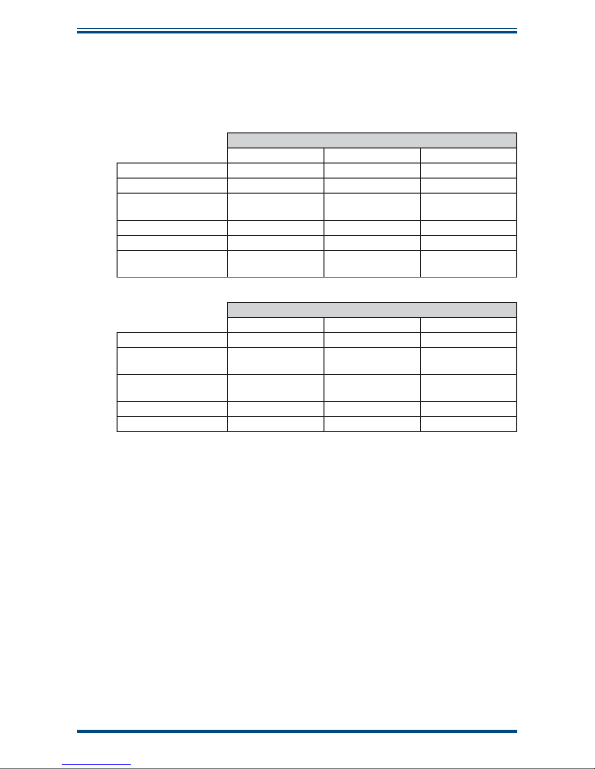
Please fi ll out the form(s) below for each instrument that has been purchased.
Use this information when contacting Michell Instruments for service purposes.
Transmitter
Code
Serial Number
Invoice Date
Location of Instrument
Tag No
Transmitter
Code
Serial Number
Invoice Date
Location of Instrument
Tag No
Transmitter
Code
Serial Number
Invoice Date
Location of Instrument
Tag No
Page 3
© 2016 Michell Instruments
This document is the property of Michell Instruments Ltd. and may not be copied or
otherwise reproduced, communicated in any way to third parties, nor stored in any Data
Processing System without the express written authorization of Michell Instruments Ltd.
Pura 2-Wire / 3-Wire / Digital Transmitter
S
/
N
o
.
E
1
1
4
-
0
7
3
P
r
o
d
u
c
t
C
o
d
e
:
P
U
R
-
T
X
2
-
W
I
R
E
P
U
R
R
a
n
g
e
-
1
2
-
For Michell Instruments' contact information please go to
www.michell.com
Page 4

Pura 2-Wire/3-Wire/Digital Transmitter
User’s Manual
iv
97070 Issue 12.1, March 2016
Contents
Safety ................................................................................................................................vi
Electrical Safety ...........................................................................................................vi
UL Approval .................................................................................................................vi
Pressure Safety ............................................................................................................vi
Toxic Materials .............................................................................................................vi
Repair and Maintenance ...............................................................................................vi
Calibration ...................................................................................................................vi
Safety Conformity ........................................................................................................vi
Abbreviations .....................................................................................................................vii
Warnings ...........................................................................................................................vii
1 INTRODUCTION ................................................................................................1
1.1 Features ............................................................................................................ 1
2 INSTALLATION ..................................................................................................2
2.1 Unpacking the Instrument ................................................................................... 2
2.2 Unpacking the Pura SEN ..................................................................................... 3
2.2.1 Unpacking Pura OEM-single bag, PREMIUM (PRM)-double bag versions ............ 3
2.3 Pura SEN ........................................................................................................... 4
2.4 Pura OEM, PRM .................................................................................................. 4
2.5 Preparation of the Transmitter Cable .................................................................... 5
2.6 Transmitter Mounting .......................................................................................... 6
2.6.1 Pura SEN - Sample Block (Optional) .............................................................. 6
2.6.2 Pura OEM & PRM Connection ......................................................................... 8
2.6.3 Pura SEN - Direct Pipeline Connection............................................................. 9
2.6.4 Transmitter Cable Connection ....................................................................... 10
3 OPERATION ....................................................................................................11
4 MAINTENANCE ................................................................................................12
5 FAULT CONDITIONS ........................................................................................13
Page 5

Pura 2-Wire/3-Wire/Digital Transmitter
User’s Manual
Michell Instruments
v
Figures
Figure 1 Transmitter Unpacking Method ....................................................................3
Figure 2 Unpacking - Pura OEM & PREMIUM (PRM) - Single / Double Bag ...................3
Figure 3 Pura SEN ...................................................................................................4
Figure 4 Pura OEM, PRM ..........................................................................................4
Figure 5 Connector Terminal Block Removal ..............................................................5
Figure 6 Rear of Connector Terminal Block - 2-wire ....................................................5
Figure 7 Electrical Connections - 2-wire .....................................................................5
Figure 8 Rear of Connector Terminal Block - 3-wire ....................................................6
Figure 9 Rear of Connector Terminal Block - 4-wire ....................................................6
Figure 10 Sensor Block Connection .............................................................................7
Figure 11 Inlet/Outlet Identifi cation ............................................................................8
Figure 12 Transmitter Mounting - Pipe or Duct.............................................................9
Figure 13 Connector Installation ...............................................................................10
Figure 14 Installation Location .................................................................................11
Figure 15 Indication of Dead Space ..........................................................................11
Figure 16 SEN Dimensional Drawing .........................................................................16
Figure 17 OEM & PRM Dimensional Drawing..............................................................16
Appendices
Appendix A Technical Specifi cations ..............................................................................15
A.1 Dimensional Drawings ..................................................................16
Appendix B EU Declaration of Conformity......................................................................18
Appendix C Quality, Recycling & Warranty Information ...................................................20
C.1 Pressure Equipment Directive (PED) 97/23/EC ...............................20
C.2 Recycling Policy ..........................................................................20
C.3 WEEE Compliance ........................................................................20
C.4 RoHS2 Compliance ......................................................................21
C.5 Warranty .....................................................................................21
C.6 REACH Compliance ......................................................................22
C.7 Calibration Facilities .....................................................................22
C.8 Return Policy ...............................................................................23
C.9 Manufacturing Quality ..................................................................23
Appendix D Return Document & Decontamination Declaration ........................................25
Page 6

Pura 2-Wire/3-Wire/Digital Transmitter
User’s Manual
vi
97070 Issue 12.1, March 2016
Safety
The manufacturer has designed this equipment to be safe when operated using the procedures
detailed in this manual. The user must not use this equipment for any other purpose than that
stated. Do not apply values greater than the maximum value stated.
This manual contains operating and safety instructions, which must be followed to ensure the safe
operation and to maintain the equipment in a safe condition. The safety instructions are either
warnings or cautions issued to protect the user and the equipment from injury or damage. Use
competent personnel using good engineering practice for all procedures in this Manual.
Electrical Safety
The instrument is designed to be completely safe when used with options and accessories supplied
by the manufacturer for use with the instrument.
UL Approval (2-wire version ONLY)
This product (2-wire version only) is UL approved within the operating temperature range of -20°C
to +60°C. The IP66 rating of this product is outside the scope of UL Approval, but this product has
been verifi ed as being IP66 by independent, UKAS accredited, 3rd party listing.
Pressure Safety
DO NOT permit pressures greater than the safe working pressure to be applied to the instrument.
The specifi ed safe working pressure is 24 MPa (240 barg / 3480 psig). Refer to Appendix A,
Technical Specifi cations.
Toxic Materials
The use of hazardous materials in the construction of this instrument has been minimized. During
normal operation, it is not possible for the user to come into contact with any hazardous substance,
which might be employed in the construction of the instrument. Care should, however, be exercised
during maintenance and the disposal of certain parts.
Repair and Maintenance
The instrument must be maintained either by the manufacturer or an accredited service agent. For
Michell Instruments’ contact information please go to www.michell.com.
Calibration
Periodic re-calibration is recommended in order to maintain the highest quality of measurement in
your application. Michell Instruments recommends that you have your Pura transmitter re-calibrated
annually unless it is used in a mission-critical application or in a contaminated environment, in which
case the calibration interval should be reduced accordingly.
Michell Instruments can offer a variety of re-calibration and exchange transmitter schemes to suit
your specifi c needs. Your local representative will be pleased to provide detailed, custom advice.
Safety Conformity
This product meets the essential protection requirements of the relevant EU directives. Further
details of applied standards may be found in the Technical Specifi cations, Appendix A.
Page 7

Pura 2-Wire/3-Wire/Digital Transmitter
User’s Manual
Michell Instruments
vii
Abbreviations
The following abbreviations are used in this manual:
barg bar gauge
°C degrees Celsius
°F degrees Fahrenheit
dp dew point
DC direct current
fps feet per second
μm micro-meter
Nl/min normal liters per minute
mA milliampere
Mpa megapascal
m/sec meters per second
Nm Newton meter
psig pounds per square inch
ppm
V
parts per million by volume
RH relative humidity
scfh standard cubic feet per hour
V volts
Ω ohms
Warnings
The following general warning listed below is applicable to this instrument. It is repeated
in the text in the appropriate locations.
Where this hazard warning symbol appears in the following
sections it is used to indicate areas where potentially
hazardous operations need to be carried out.
Page 8

Pura 2-Wire/3-Wire/Digital Transmitter
User’s Manual
Michell Instruments
1
INTRODUCTION
1 INTRODUCTION
The Pura Series of transmitters has been manufactured, tested and calibrated to
the highest available standards and should arrive in perfect working order, ready for
installation into a gas measurement application.
If there are any questions about the transmitter or how to install it, not detailed in
this Manual, contact your local representative. Refer to www.michell.com for details of
Michell Instruments’ worldwide offi ces’ contact information.
1.1 Features
The Pura Series are a continuous, on-line, 4-20 mA/digital transmitter family for the
measurement of moisture content in air and other non-corrosive gases.
Their key features are:
• Accuracy ±1°C dp
• 0.5°Cdp (0.9°Fdp) repeatability
• 2-wire connection - linear 4–20 mA signal
• 3-wire connection - linear 4-20 mA signal
• Digital transmitter - 4-wire connection - digital string signal (NOTE: only
works with the Pura AOL monitor)
• Operating pressure range - up to 24 MPa (240 barg / 3480 psig)
• Operating range - 120 to -40°Cdp (-184 to -40°Fdp)
• Moisture content ppm
V
(2-wire)
• Powered by any DC source from 12 to 28 V
Page 9
Pura 2-Wire/3-Wire/Digital Transmitter
User’s Manual
2
97070 Issue 12.1, March 2016
INSTALLATION
2 INSTALLATION
2.1 Unpacking the Instrument
On delivery, check that all the following standard components are present in the packing
box:
Pura SEN (transmitter, no block version)
2-wire 3-wire Digital Transmitter
Calibration Certifi cate
Transmitter Connector
Connector Gasket
Round
Square
Square
97070 User’s Manual
Leak Test Certifi cate
VCR Seal
(for sample block)
Pura OEM / Pura PREMIUM (PRM)
2-wire 3-wire Digital Transmitter
Calibration Certifi cate
Transmitter Connector
Already Fitted
Already Fitted
Already Fitted
Connector Gasket
Round
Square
Square
97070 User’s Manual
Leak Test Certifi cate
NOTE: If any component is not present in the packing box, contact Michell
Instruments immediately.
NOTE: Packing tube and foam protectors are not needed for operation. Save
all the packing materials for the purpose of returning the instrument for recalibration or any warranty claims.
Page 10
Pura 2-Wire/3-Wire/Digital Transmitter
User’s Manual
Michell Instruments
3
INSTALLATION
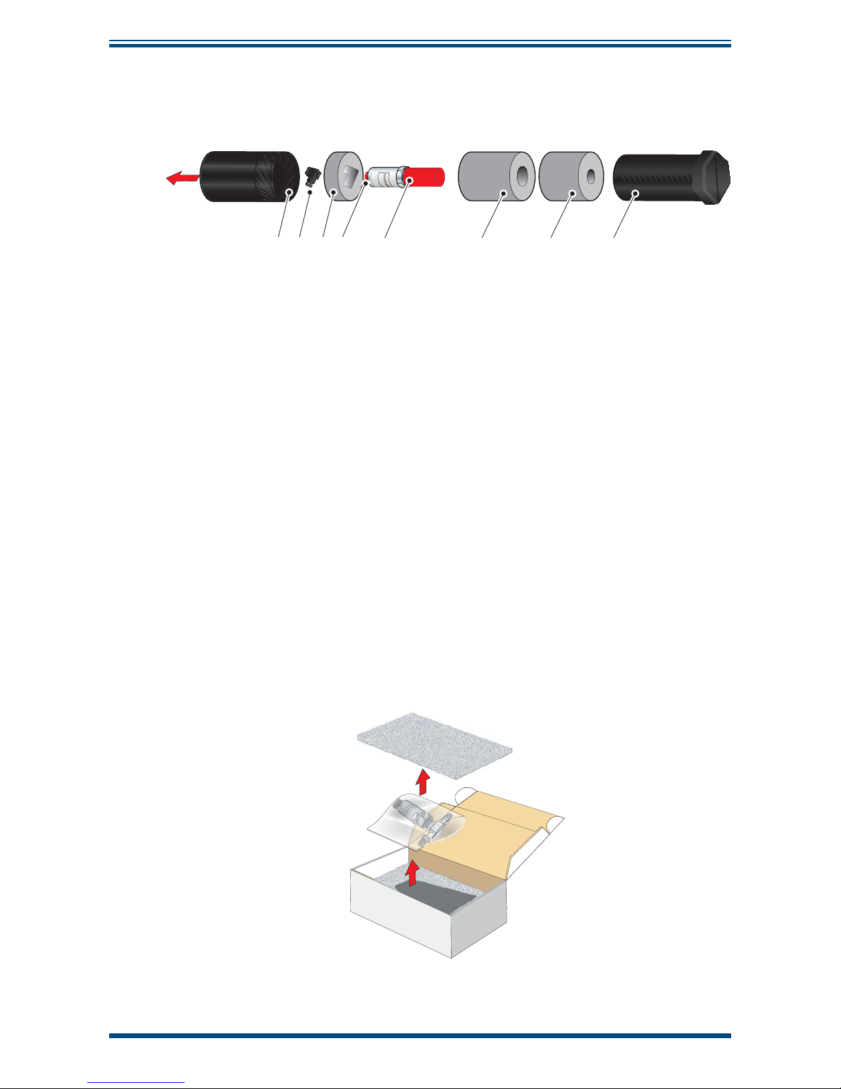
2.2 Unpacking the Pura SEN
Unpack the dew-point transmitter packing tube as follows (see
Figure 1).
87645321
Figure 1
Transmitter Unpacking Method
1. Unscrew the cap (1) from the packing tube (8).
2. Remove the foam block (3) containing the connector (2).
3. Pull out the transmitter (5) from the tube, complete with the two foam
covers (6) and (7), the red protective cap (4) and the connector gasket
(3-wire or digital sensor only).
4. Remove the foam covers from the transmitter but leave the red plastic
protective cover (5), the red cap (4) and the connector gasket in place
until ready for installation.
NOTE: The transmitter sensing element is protected while in transit by a red
cover containing a small desiccant capsule. The connection pins are protected
by a red plastic cap. None of these plastic items are required for the operation
of the transmitter.
NOTE: Keep the connector (2) in a safe place until the transmitter is ready
for wiring.
2.2.1 Unpacking Pura OEM-single bag, PREMIUM (PRM)-double bag versions
Figure 2
Unpacking - Pura OEM & PREMIUM (PRM) - Single / Double Bag
Page 11
Pura 2-Wire/3-Wire/Digital Transmitter
User’s Manual
4
97070 Issue 12.1, March 2016
INSTALLATION
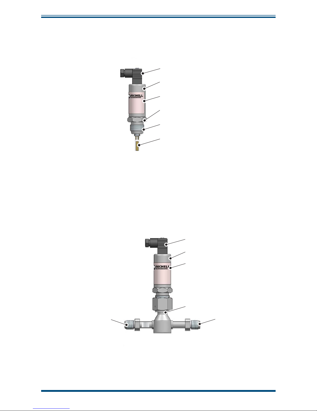
2.3 Pura SEN
NOTE: For environmental and operating conditions, refer to Appendix A,
Technical Specifi cations.
Electrical connector
Transmitter cover
Transmitter label
Hexagonal nut
Process connection (½” VCR)
Sensing element
Figure 3
Pura SEN
2.4 Pura OEM, PRM
NOTE: For environmental and operating conditions refer to Appendix A,
Technical Specifi cations.
NOTE: The OEM and PRM transmitters are protected in transit by putting in a
plastic bag fi lled with nitrogen. The Pura OEM has single bag protection and
the Pura PRM has double bag protection.
Electrical connector
Transmitter cover
Transmitter label
Sensor block
Gas inlet (¼” VCR)
(see note below)
Gas outlet
(¼” VCR)
NOTE: The Pura has a uni-directional connection and must be
connected so the upstream flow is connected to the inlet port
of the Pura block (marked with a silver label).
INLET
Figure 4
Pura OEM, PRM
Page 12

Pura 2-Wire/3-Wire/Digital Transmitter
User’s Manual
Michell Instruments
5
INSTALLATION
2.5 Preparation of the Transmitter Cable
The transmitter cable is NOT supplied as standard. A cable can be obtained by contacting
your local distributor or Michell Instruments (see www.michell.com for details).
Cable connection to the Pura transmitter is made via the removable connector. Removing
the central screw enables the connector terminal block to be removed from the outer
housing by using a small screwdriver to prise it clear.
i
O-ring
and washer
Figure 5
Connector Terminal Block Removal
Caution: When removing the central screw ensure that the
small sealing O-ring and the washer are retained on the screw
and are present during re-installation.
For the transmitter to work properly, and to achieve maximum performance, the
transmitter cable must be connected to the transmitter connector as shown in the
drawings below:
2-wire
h
h
Supply
4-20 mA
PIN 3
PIN 1
(GND)
Screen/Shield
Optional
Figure 6
Rear of Connector Terminal Block - 2-wire
Always connect the 4-20 mA return signal to a suitable load
before the power is applied. Without this connection the sensor
may be damaged if allowed to operate for prolonged periods.
3
1
Max Load
250R @ 12V
500R @ 24V
Supply
12V Min
28V Max
+
Figure 7
Electrical Connections - 2-wire
Page 13

Pura 2-Wire/3-Wire/Digital Transmitter
User’s Manual
6
97070 Issue 12.1, March 2016
INSTALLATION
3-wire
4-20 mA (Source)
PIN 3
PIN 1
(GND)
GROUND (System 0 V)
and Cable Screen
Power (+12 V to +24 V)
Figure 8
Rear of Connector Terminal Block - 3-wire
4-wire Digital String
NOTE: Digital String will only work with Pura AOL Monitor
YELLOW
GREEN
BLUE
RED
PIN 3
PIN 2
RED
+Power
YELLOW
Signal (A)
GREEN
Signal (B)
PIN 1
BLUE
Ground
1
2
3
4
YELLOW Signal (A)
GREEN Signal (B)
BLUE Screen
RED +Power
Figure 9
Rear of Connector Terminal Block - 4-wire
2.6 Transmitter Mounting
2.6.1 Pura SEN - Sample Block (Optional)
Prior to installation of the transmitter, unscrew and remove the red plastic cover and
HDPE guard and retain for future use. Take care to prevent any contamination of the
transmitter before installation - handle the transmitter by the main body only,
avoiding contact with the sensor guard.
The recommended gas fl ow rate, when mounted in the optional sampling block, is 1 to
5 Nl/min (2.1 to 10.6 scfh). However, for direct insertion applications, gas fl ow should
be from static to 10 m/sec (32.8 fps).
Page 14

Pura 2-Wire/3-Wire/Digital Transmitter
User’s Manual
Michell Instruments
7
INSTALLATION
The following procedure must be carried out by a qualifi ed
installation engineer.
To mount the transmitter into the sensor block (preferred method), proceed as follows
(see
Figure 10)
:
1. Remove the red protective cover (2) from the tip of the transmitter
(1).
2. Fit the ½” VCR gasket (3) over the threaded part of the transmitter
body.
WARNING: Under no circumstances should the fi lter guard be
handled with the fi ngers.
3. Screw the transmitter (1) into the sensor block (4) and, holding
the Pura transmitter stationary with a spanner/wrench, tighten the
gas line nut 1/8 of a turn using a second spanner/wrench. NOTE:
Use the fl ats of the hexagonal nut and not the transmitter
body.
4. Fit the transmitter cable/connector assembly to the plug located
on the base of the transmitter and tighten the fi xing screw (see
Figure 5).
P
u
r
a
T
r
a
n
s
m
i
t
t
e
r
0
9
0
6
R
a
n
g
e
:
1
0
0
/
+
2
0
4
8
L
a
n
c
a
s
t
e
r
W
a
y
B
E
l
y
,
C
a
m
b
r
i
d
g
e
s
C
B
6
3
N
U
n
i
t
e
d
K
i
n
g
I
C
H
E
I
n
s
t
r
u
m
e
n
P
u
r
a
T
r
a
n
s
m
i
t
t
e
r
0
9
0
6
R
a
n
g
e
:
1
0
0
/
+
2
0
4
8
L
a
n
c
a
s
t
e
r
W
a
y
B
E
l
y
,
C
a
m
b
r
i
d
g
e
s
C
B
6
3
N
U
n
i
t
e
d
K
i
n
g
M
I
C
H
E
I
n
s
t
r
u
m
e
n
E
E
P
u
r
a
T
r
a
n
s
m
i
t
t
e
r
0
9
0
6
R
a
n
g
e
:
-
1
0
0
/
+
2
0
4
8
L
a
n
c
a
s
t
e
r
W
a
y
B
E
l
y
,
C
a
m
b
r
i
d
g
e
s
C
B
6
3
N
U
n
i
t
e
d
K
i
n
g
M
I
C
H
E
I
n
s
t
r
u
m
e
n
E
1
2
3
4
Figure 10
Sensor Block Connection
Page 15

Pura 2-Wire/3-Wire/Digital Transmitter
User’s Manual
8
97070 Issue 12.1, March 2016
INSTALLATION
2.6.2 Pura OEM & PRM Connection
The Pura OEM and PRM have been assembled and packaged within a Class 100 cleanroom environment. To maintain this level of cleanliness the packaging should only be
opened within the same, or cleaner, environment.
Michell Instruments recommends the use of Swagelok
®
retained gasket assemblies,
containing silver plated, stainless steel ¼” VCR gaskets, when connecting the Pura into
a gas line. The distance between the inlet and outlet gas connection ports is set at a
pitch of 120mm (4.7”).
1. Install the sealing gasket onto the VCR connections on either the
Pura or the connecting gas lines. Ensure that the Pura is offered
into the gas line with reference to the gas fl ow direction and the
inlet port, as indicated on the Pura body.
Inlet
Outlet
Figure 11
Inlet/Outlet Identifi cation
NOTE: In order to identify the Inlet and Outlet without
dismantling the instrument it is necessary to look through the
Inlet/Outlet holes. Looking through the INLET hole a shiny end
can be seen, looking through the OUTLET hole an elongated
shape can be seen.
2. Tighten the female nut fi rmly, fi nger tight.
3. Hold the Pura transmitter stationary with a spanner/wrench and
tighten the gas line nut 1/8 of a turn using a second spanner/
wrench.
4. Repeat this operation on the remaining gas connection port.
CAUTION: Over-tightening the nuts can cause irrecoverable
damage to the seals and seatings.
Page 16

Pura 2-Wire/3-Wire/Digital Transmitter
User’s Manual
Michell Instruments
9
INSTALLATION
2.6.3 Pura SEN - Direct Pipeline Connection
The transmitter may be directly mounted into a pipe or duct
.
CAUTION: Do not mount the transmitter too close to the
bottom of a bend where any condensate in the pipeline might
collect and saturate the probe.
The pipe or duct will require a ½” VCR male process connection thread to match
the transmitter body thread. Fixing dimensions are shown in
Figure 12.
For circular
pipework, to ensure the integrity of a gas tight seal, a mounting fl ange will be required
on the pipework in order to provide a fl at surface to seal against.
Procedure
The following procedure must be carried out by competent
personnel.
1. Ensure that the red protective cover has been removed from the
tip of the transmitter.
WARNING: Under no circumstances should the fi lter guard be
handled with the fi ngers.
2. After fi rst checking that the pipeline has a wide enough bore to
accept the transmitter’s process connection, screw the transmitter
into the pipe. Tighten enough to obtain a gas tight seal. (Torque
will depend upon the pipeline material.)
Michell Instruments recommends the use of Swagelok® retained gasket assemblies,
containing silver plated, stainless steel ½” VCR gaskets, when connecting the Pura into
a gas line.
NOTE: Do not overtighten or the thread on the pipework may be stripped.
(1.9”)
1
1
2
2
3
3
Optional
display
(available
on request)
Optional
cable
(available
on request)
j
j
48mm
Figure 12
Transmitter Mounting - Pipe or Duct
Page 17

Pura 2-Wire/3-Wire/Digital Transmitter
User’s Manual
10
97070 Issue 12.1, March 2016
INSTALLATION
2.6.4 Transmitter Cable Connection
When installing the connector, and to ensure that full ingress protection is achieved, the
securing screw (with the O-ring and washer) must be tightened to a minimum torque
setting of 3.4 Nm (2.5 ft-lbs). The transmitter cable used must be a minimum diameter
of 4.6mm (0.2”).
4
8
L
a
n
c
a
s
t
e
r
W
a
y
B
E
l
y
,
C
a
m
b
r
i
d
g
e
C
B
6
3
N
P
u
r
a
T
r
a
n
s
m
i
t
t
e
r
R
a
n
g
e
:
-
1
0
0
/
+
2
0
4
8
L
a
n
c
a
s
t
e
r
W
a
y
B
E
l
y
,
C
a
m
b
r
i
d
g
e
C
B
6
3
N
O-ring
and washer
i
P
u
r
a
T
r
a
n
s
m
i
t
t
e
R
a
n
g
e
:
-
1
0
0
/
+
2
0
Figure 13
Connector Installation
Page 18

Pura 2-Wire/3-Wire/Digital Transmitter
User’s Manual
Michell Instruments
11
OPERATION
3 OPERATION
Operation is very simple assuming the following installation techniques are adhered to:
Sampling Hints
Be Sure the Sample is Representative of the Gas Under Test:
The sample point should be as close to the critical measurement point as possible. Also,
never sample from the bottom of a pipe as entrained liquids may be drawn into the
sensing element.
Figure 14
Installation Location
Minimize Dead Space in Sample Lines:
Dead space causes moisture entrapment points, increased system response times, and
measurement errors as a result of the trapped moisture being released into the passing
sample gas and causing an increase in partial vapor pressure.
Deadspace
Figure 15
Indication of Dead Space
Remove Any Particulate Matter or Oil from the Gas Sample:
Particulate matter at high velocity can damage the sensing element and similarly, at
low velocity, they may ‘blind’ the sensing element and reduce its response speed. If
particulate, such as degraded desiccant, pipe scale or rust is present in the sample gas,
use an in-line fi lter, as a minimum level of protection. For more demanding applications
Michell Instruments offers a range of sampling systems (for more information contact
www.michell.com).
Use High Quality Sample Tube and Fittings:
Michell Instruments recommends that, wherever possible, stainless steel tubing and
fi ttings should be used. This is particularly important at low dew points since other
materials have hygroscopic characteristics and adsorb moisture on the tube walls,
slowing down response and, in extreme circumstances, giving false readings. For
temporary applications, or where stainless steel tubing is not practical, use high quality
thick walled PTFE tubing.
Position Transmitter away from Heat Source:
It is recommended, as good instrumentation practice, that the transmitter is placed
away from any heat source to avoid adsorption/desorption.
Page 19

Pura 2-Wire/3-Wire/Digital Transmitter
User’s Manual
12
97070 Issue 12.1, March 2016
MAINTENANCE
4 MAINTENANCE
Calibration
Routine maintenance of the Pura is confi ned to regular re-calibration by exposure of
the Pura to sample gases of known moisture content to ensure that the stated accuracy
of the Pura is maintained. Calibration services traceable to the UK
National Physical
Laboratory
(NPL) and the US
National Institute of Standards and Technology
(NIST) are
provided by Michell Instruments.
Michell Instruments offers a re-calibration service to suit specifi c needs. A Michell
representative can provide detailed, custom advice (for Michell Instruments’ contact
information go to www.michell.com).
Page 20

Pura 2-Wire/3-Wire/Digital Transmitter
User’s Manual
Michell Instruments
13
FAULT CONDITIONS
5 FAULT CONDITIONS
2-wire & 3-wire 4-20 mA Output Only
Message
Displayed
Cause Action
Current output is
0 mA constantly
Power failure
Check power supply to transmitter
Check transmitter cable for
continuity/damage
Rectify/replace cable
Instrument failure Contact instrument supplier
Current output is
4 mA constantly
Transmitter desiccated Check gas source supply
Transmitter contaminated Replace/re-calibrate transmitter
Current output is
20 mA constantly
Gas is wetter than -40°Cdp
(-40°Fdp)
Check gas source supply
Transmitter contaminated Replace/re-calibrate transmitter
Current output is
23 mA constantly
Instrument failure Contact instrument supplier
Digital String - See Pura AOL Manual
Page 21

Pura 2-Wire/3-Wire/Digital Transmitter
User’s Manual
14
97070 Issue 12.1, March 2016
APPENDIX A
Appendix A
Technical Specifi cations
Page 22

Pura 2-Wire/3-Wire/Digital Transmitter
User’s Manual
Michell Instruments
15
APPENDIX A
Appendix A Technical Specifi cations
Performance Specifi cations
Pura 2-Wire
Pura 3-Wire /
Digital Transmitter
Measurement Range (dp) -120 to -40°C (-184 to -40°F) dew point
Accuracy (dp)
±1°C from -40 to -60°C (-40 to -76°F)
±2°C from -60 to -100°C (-76 to -148°F)
±4°C from -100 to -120°C (-148 to -184°F) (estimated)
Repeatability 0.5°C (0.9°F) dew point
Electrical Specifi cations
Output Signal
4-20 mA, 2-wire connection,
current source
(user-confi gurable over range
using communication kit and
software)
3-wire 4-20 mA, 3-wire
connection, current source (user-
confi gurable over range using
communication kit and software)
Digital Transmitter, digital string
(signal), 4-wire connection (user-
confi gurable over range via monitor
front panel)
Output
Dew point or moisture content
for ppm
V
Dew point
Output Range -120 to -40°Cdp (-184 to -40°Fdp)
Supply Voltage 12 to 28 V DC
Load Resistance
Max 250 Ω @ 12 V
(500 Ω @ 24 V)
Max 300 Ω @ 12 V
(900 Ω @ 24 V)
Current Consumption 23 mA
Supply Voltage Infl uence
±0.005% RH/V
Operating Specifi cations
Operating Humidity 0 -100% RH
Operating Temperature -40 to +60°C (-40 to +140°F)
Operating Pressure 24 MPa (240 barg / 3480 psig)
Flow Rate 1 to 10 Nl/min (2.1 to 21.2 scfh) (5 Nl/min (10.6 scfh) optimum)
Mechanical Specifi cations
Ingress Protection
IP66 in accordance with standard BS EN 60529:1992
NEMA 4 in protection accordance with standard NEMA 250-2003
Housing Material Stainless steel
Mounting Thread
¼” male VCR gas in/out connections
½” male VCR sensor connection
Weight
PRM and OEM versions: 450g (15.87oz)
Pura SEN version: 180g (6.34oz)
Interchangeability
Fully interchangeable transmitter
(of same type only - i.e. 2-wire with 2-wire)
Electrical Connections Screw terminal
Fault Conditions
(factory programmed)
Condition
Sensor fault
Under-range dew point
Over-range dew point
Output
23 mA
4 mA
20 mA
Page 23
Pura 2-Wire/3-Wire/Digital Transmitter
User’s Manual
16
97070 Issue 12.1, March 2016
APPENDIX A
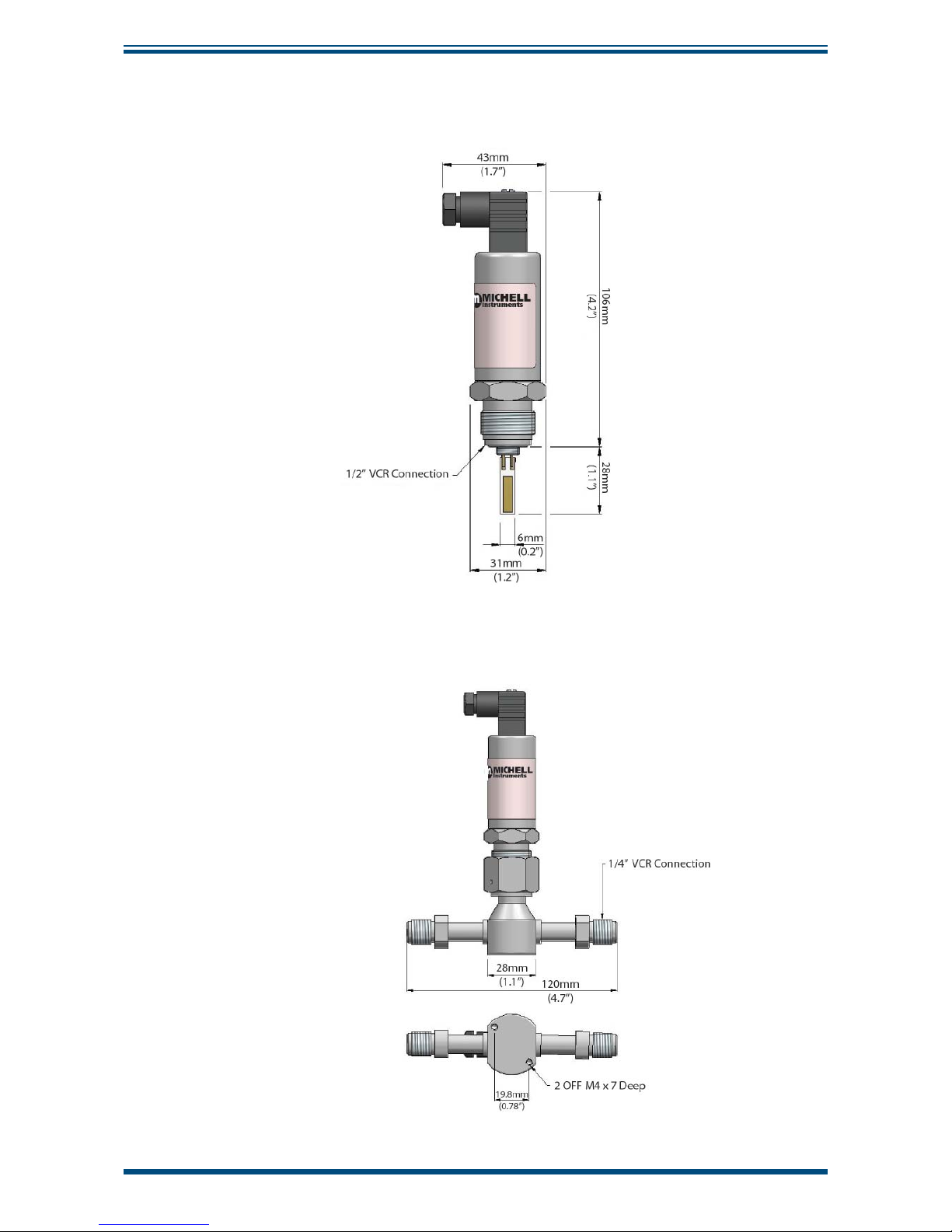
A.1 Dimensional Drawings
Pura Transmitter (SEN)
Figure 16
SEN Dimensional Drawing
Pura OEM & Pura Premium (PRM)
Figure 17
OEM & PRM Dimensional Drawing
Page 24

Pura 2-Wire/3-Wire/Digital Transmitter
User’s Manual
Michell Instruments
17
APPENDIX B
Appendix B
EC Declaration of Conformity
Page 25

Pura 2-Wire/3-Wire/Digital Transmitter
User’s Manual
18
97070 Issue 12.1, March 2016
APPENDIX B
Appendix B EU Declaration of Conformity
Page 26

Pura 2-Wire/3-Wire/Digital Transmitter
User’s Manual
Michell Instruments
19
APPENDIX C
Appendix C
Quality, Recycling
& Warranty
Information
Page 27

Pura 2-Wire/3-Wire/Digital Transmitter
User’s Manual
20
97070 Issue 12.1, March 2016
APPENDIX C
Appendix C Quality, Recycling & Warranty Information
C.1 Pressure Equipment Directive (PED) 97/23/EC
The above Directive has been implemented in United Kingdom Law by the Pressure Equipment
Regulations 1999.
The Regulations require that all pressure equipment and assemblies within the scope of the Pressure
Equipment Directive must be safe when placed on the market or put into service.
Michell Instruments’ products have been assessed and, as referenced against the Classifi cation Charts
detailed in Annex II of the Directive, do not fall into the requirements for CE marking compliance
with the Pressure Equipment Directive.
Article 3, paragraph 3 states that any product containing a pressurized fl uid that does not qualify for
compliance should, nevertheless, be constructed with Sound Engineering Practice (SEP).
Michell Instruments attests here that its products have been designed, manufactured & tested to
assure safe operation, and in accordance with Sound Engineering Practices.
C.2 Recycling Policy
Michell Instruments is concerned with the protection of the environment. It is our commitment to
reduce and eliminate from our operations, wherever possible, the use of substances which may be
harmful to the environment. Similarly, we are increasingly using recyclable and/or recycled material
in our business and products wherever it is practical to do so.
To protect natural resources and to promote material reuse, please separate batteries from other
types of waste and recycle responsibly. If batteries are not properly disposed of, these substances
can cause harm to human health and the environment.
The product that you have purchased may contain recyclable and/or recycled parts and we will be
happy to provide you with information on these components if required. For further information
please see the following sections.
C.3 WEEE Compliance
Directive 2012/19/EU 4 July 2012 on Waste Electronic and Electrical Equipment (WEEE)
The Waste Electronic and Electrical Equipment (WEEE) Directive places rules upon European
manufacturers of electrical and electronic equipment. The directives’ aim is to reduce the impact
that electronic devices have on the environment.
Michell Instruments is in full compliance with the WEEE Directive and is registered with an approved
recycler (Registration No. WEE/JB0235YW) and treats the requirement of the directive and the
protection of the environment with the utmost importance. All Michell Instruments’ products are
appropriately marked indicating their requirement for recycling.
It may be required to return certain instruments for treatment at the end of their working life.
Feb 2013
Page 28

Pura 2-Wire/3-Wire/Digital Transmitter
User’s Manual
Michell Instruments
21
APPENDIX C
C.4 RoHS2 Compliance
Directive 2011/65/EU of the European Parliament and of the Council of 8 June 2011
The Restriction of Hazardous Substances (RoHS) Directive places rules upon European manufacturers
of electrical and electronic equipment. The directives’ aim is to reduce the impact that electronic
devices have on the environment.
According to the EC Directive 2002/95/EC, Michell Instruments’ products qualify as Category 9,
Control and Monitoring Equipment. Under the 2002/95/EC Directive, Category 9 products are exempt
from compliance with the Directive.
However, the careful design of all Michell Instruments’ products takes into consideration the
requirements of the Directive and, wherever possible, compliance is achieved. All future products
will be developed entirely using compliant materials. Furthermore, Michell Instruments is taking
active steps to remove non-compliant materials and components from existing products wherever
these may occur. Presently, none of the non-compliant materials are known to occur in Michell
Instruments’ products.
The new Directive 2011/65/EU (RoHS2) entered into force on 21 July 2011 and required all Member
States to transpose the provisions into their respective national laws by 2 January 2013.
Under the provisions of the RoHS2 EU Directive 2011/65/EU (Article 3, [24]) defi nes ‘Control and
Monitoring Equipment’ specifi cally as ‘monitoring and control instruments designed exclusively for
industrial or professional use’.
RoHS2 EU Directive 2011/65/EU states the closing date for compliance of any Control and Monitoring
Equipment product sold into the EU market place as 22nd July 2017.
However, the careful design policy of all Michell Instruments’ products continues to attain compliance
in the shortest practical timescales and strives to ensure that less than 0.1% of total mass per
product, of all non-compliant materials, appear within them. Michell Instruments continues to
monitor suppliers and material sources to ensure that compliance of goods provided is maintained.
January 2013
C.5 Warranty
Unless otherwise agreed, the Supplier warrants that, as from the date of delivery for a period of 12
months, the goods and all their component parts, where applicable, are free from any defects in
design, workmanship, construction or materials.
The Supplier warrants that the services undertaken shall be performed using reasonable skill and
care, and be of a quality conforming to generally accepted industry standards and practices.
Except as expressly stated, all warranties whether express or implied, by operation of law or
otherwise, are hereby excluded in relation to the goods and services to be provided by the Supplier.
All warranty services are provided on a return to base basis. Any transportation costs for the return
of a warranty claim shall reside with the Customer.
Page 29

Pura 2-Wire/3-Wire/Digital Transmitter
User’s Manual
22
97070 Issue 12.1, March 2016
APPENDIX C
C.6 REACH Compliance
Regulation (EC) No. 1907/2006
Registration, Evaluation, Authorisation and Restriction of Chemicals (REACH)
Michell Instruments is a manufacturer of moisture measurement and gas analysis instrumentation
and is a ‘downstream’ user of chemicals, as described by the EU Council Directive 76/769/EEC. The
products we supply are not raw chemical products (goods).
Under normal and reasonably foreseeable circumstances of application, the goods supplied to you
shall not contain or release any prohibited chemicals. No listed SVHC (Substances of Very High
Concern) appear within products manufactured by Michell Instruments. Therefore the 0.1% mass
per product, or total usage of 1 tonne/year, will never be exceeded. For these reasons we are neither
required by obligation for registration nor for the creation of material safety data sheets (MSDS) for
our products.
Our continued review of the SVHC Candidate List and
latest additions is to ensure we remain
compliant.
Michell Instruments maintains a hazardous material register in which MSDS data sheets are collated,
and we will check that our suppliers will comply to REACH requirements for all materials and
substances we use in the processes of our manufacturing.
In the unlikely event that any chemicals of concern appear in our products in quantities greater than
0.1% of total mass per product we will immediately inform you by correspondence according to the
REACH Article 33 requirements. Our current appraisal is, however, that we do not expect or foresee
such an incidence.
January 2013
C.7 Calibration Facilities
Michell Instruments’ calibration facilities are among the most sophisticated in the world and have
been recognized for their excellence.
Traceability to the National Physical Laboratory (NPL) UK is achieved through our UKAS Accreditation
(Number 0179). This covers dew point over the range -90 to +90°C (-130 to +194°F) and also
Relative Humidity.
Dew-point calibrations are also traceable to the National Institute for Standards & Technology (NIST)
USA over the range -75 to +20°C (-103 to +68°F).
NOTE: Standard traceable calibration certifi cates for instruments and sensors are not
issued under our UKAS accreditation. UKAS certifi cates are usually to special order and
are clearly identifi ed.
Page 30

Pura 2-Wire/3-Wire/Digital Transmitter
User’s Manual
Michell Instruments
23
APPENDIX C
C.8 Return Policy
If a Michell Instruments’ product malfunctions within the warranty period, the following procedure
must be completed:
1. Notify a Michell Instruments’ distributor, giving full details of the problem, the
model variant and the serial number of the product.
2. If the nature of the problem indicates the need for factory service then the
instrument should be returned to Michell Instruments, carriage prepaid, preferably
in the original packaging, with a full description of the fault and the customer
contact information.
3. Upon receipt, Michell Instruments will evaluate the product to determine the cause
of the malfunction. Then, one of the following courses of action will be taken:
• If the fault is covered under the terms of the warranty, the
instrument will be repaired at no cost to the owner and returned.
• If Michell Instruments determines that the fault is not covered
under the terms of the warranty, or if the warranty has expired,
an estimate for the cost of the repairs, at standard rates, will be
provided. Upon receipt of the owner’s approval to proceed, the
product will be repaired and returned.
C.9 Manufacturing Quality
Michell Instruments is registered with the British Standards Institute for Quality Assurance to:
BS EN ISO 9001: 2008
Rigorous procedures are performed at every stage of production to ensure that the materials of
construction, manufacturing, calibration and fi nal test procedures meet the requirements laid down
by our BSI approved Quality System.
Please contact Michell Instruments (www.michell.com) if the product does not arrive in perfect
working order.
Page 31

Pura 2-Wire/3-Wire/Digital Transmitter
User’s Manual
24
97070 Issue 12.1, March 2016
APPENDIX D
Appendix D
Return Document &
Decontamination Declaration
Page 32

Pura 2-Wire/3-Wire/Digital Transmitter
User’s Manual
Michell Instruments
25
APPENDIX D
Appendix D Return Document & Decontamination Declaration
F0121, Issue 2, December 2011
'HFRQWDPLQDWLRQ&HUWL¿FDWH
IMPORTANT NOTE: Please complete this form prior to this instrument, or any components, leaving your
site and being returned to us, or, where applicable, prior to any work being carried out by a Michell
engineer at your site.
Instrument Serial Number
Warranty Repair? YES NO Original PO #
Company Name Contact Name
Address
Telephone # E-mail address
Reason for Return /Description of Fault:
Has this equipment been exposed (internally or externally) to any of the following?
Please circle (YES/NO) as applicable and provide details below
Biohazards YES NO
Biological agents YES NO
Hazardous chemicals YES NO
Radioactive substances YES NO
Other hazards YES NO
Please provide details of any hazardous materials used with this equipment as indicated above (use continuation sheet
if necessary)
Your method of cleaning/decontamination
Has the equipment been cleaned and decontaminated? YES NOT NECESSARY
Michell Instruments will not accept instruments that have been exposed to toxins, radio-activity or bio-hazardous
PDWHULDOV)RUPRVWDSSOLFDWLRQVLQYROYLQJVROYHQWVDFLGLFEDVLFÀDPPDEOHRUWR[LFJDVHV DVLPSOHSXUJHZLWKGU\
JDVGHZSRLQW&RYHUKRXUVVKRXOGEHVXI¿FLHQWWRGHFRQWDPLQDWHWKHXQLWSULRUWRUHWXUQ
Work will not be carried out on any unit that does not have a completed decontamination declaration.
Decontamination Declaration
I declare that the information above is true and complete to the best of my knowledge, and it is safe for Michell
personnel to service or repair the returned instrument.
Name (Print) Position
Signature Date
Page 33

Pura 2-Wire/3-Wire/Digital Transmitter
User’s Manual
26
97070 Issue 12.1, March 2016
NOTES:
Page 34

Pura 2-Wire/3-Wire/Digital Transmitter
User’s Manual
Michell Instruments
27
NOTES:
Page 35

Pura 2-Wire/3-Wire/Digital Transmitter
User’s Manual
28
97070 Issue 12.1, March 2016
NOTES:
Page 36

http://www.michell.com
 Loading...