

Page 1
Pura
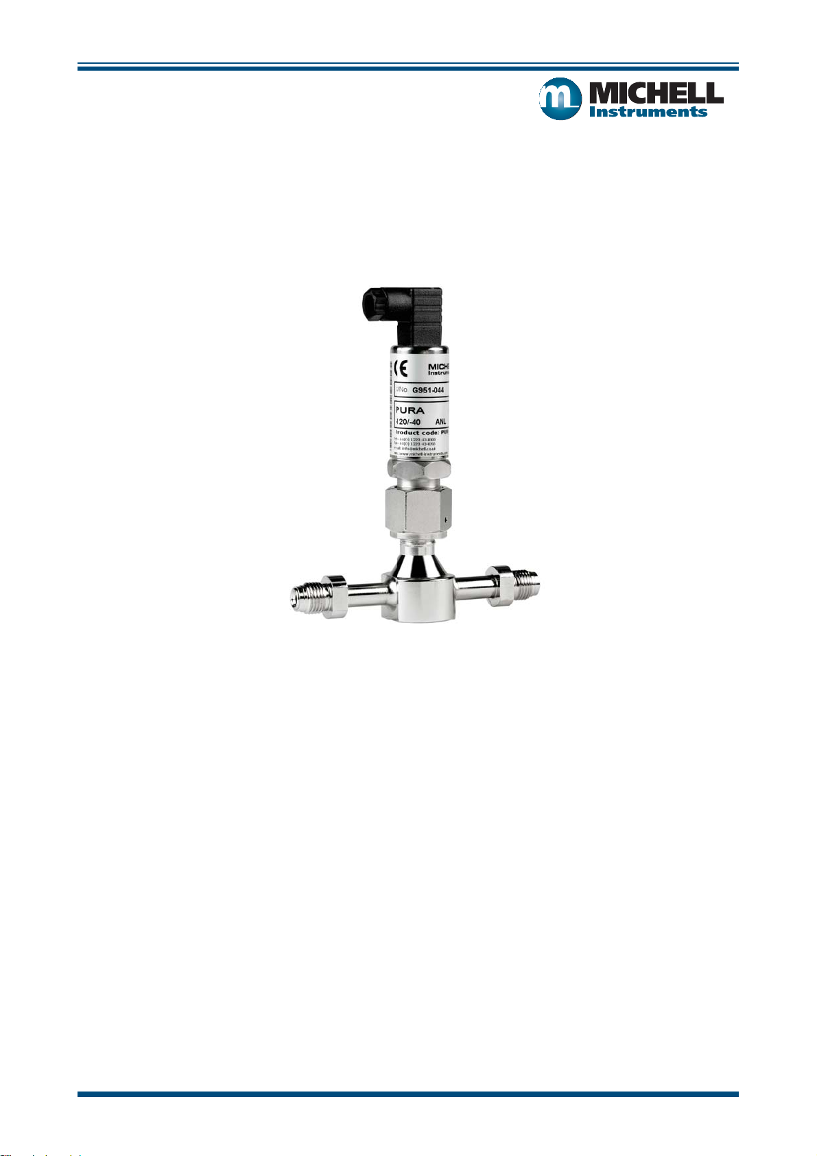
Hazardous Area Transmitter 2-wire
User’s Manual
97306 Issue 1.1, March 2016
Michell Instruments
Page 2

Inside front cover (blank)
Page 3
Pura Hazardous Area Transmitter 2-Wire User’s Manual
I.S.
Pura Hazardous Area Transmitter
© 2007-2012 Michell Instruments
This document is the property of Michell Instruments Ltd. and may not be copied or otherwise reproduced,
communicated in any way to third parties, nor stored in any Data Processing System without the express
written authorization of Michell Instruments Ltd.
97306 Issue 1.1, March 2016 iii Michell Instruments
Page 4

Pura Hazardous Area Transmitter 2-Wire User’s Manual
Contents
Safety ..............................................................................................................................................vi
Electrical Safety .........................................................................................................................vi
Pressure Safety .........................................................................................................................vi
Toxic Materials ..........................................................................................................................vi
Repair and Maintenance.............................................................................................................vi
Calibration ................................................................................................................................vi
Safety Conformity ......................................................................................................................vi
EC Declaration of Conformity.............................................................................................................vii
Abbreviations .................................................................................................................................. viii
Warnings ........................................................................................................................................ viii
Recycling Policy .................................................................................................................................ix
WEEE And RoHS Compliance ..............................................................................................................ix
Calibration Facilities ...........................................................................................................................ix
Manufacturing Quality ........................................................................................................................ix
Warranty .......................................................................................................................................... x
Return Policy ..................................................................................................................................... x
1 INTRODUCTION ........................................................................................................................ 1
2 DESCRIPTION ........................................................................................................................... 1
3 PREPARATION FOR USE ............................................................................................................. 2
4 SENSOR INSTALLATION ............................................................................................................. 3
4.1 Installing the Sensor ....................................................................................................... 3
4.2 Pura Transmitter (Sensor Only Version) Installation ........................................................... 4
4.3 Transmitter Cable .......................................................................................................... 6
4.4 Preparation of the Sensor Cable ....................................................................................... 7
4.5 Installation in Hazardous Areas ........................................................................................ 9
5 WHICH GASES TO MEASURE? .................................................................................................... 9
6 MAINTENANCE .......................................................................................................................... 9
7 FAULT CONDITIONS .................................................................................................................10
7.1 Sampling Hints ..............................................................................................................10
97306 Issue 1.1, March 2016 iv Michell Instruments
Page 5

Pura Hazardous Area Transmitter 2-Wire User’s Manual
Figures
Figure 4.1 Pura Premium & Pura OEM Dimensional Drawings ....................................................3
Figure 4.2 Pura Sensor Dimensional Drawing ...........................................................................5
Figure 4.3 Terminal block Removal ..........................................................................................6
Figure 4.4 Bare wires .............................................................................................................7
Figure 4.5
Figure 4.6 Cut to 5mm ...........................................................................................................7
Figure 4.7 Connection to Pura I.S.TX ......................................................................................7
Figure 4.8 Rear of connector terminal block .............................................................................8
Figure 4.9 Electrical Connections ............................................................................................8
Figure 7.1 Installation location .............................................................................................. 10
Figure 7.2 Indication of dead space ......................................................................................10
Crimped wires .......................................................................................................7
Appendices
Appendix A Technical Specifi cations ......................................................................................... 12
Appendix B Hazardous Area Certifi cation .................................................................................. 14
B1 Terminal Parameters ................................................................................. 14
B2 Special Conditions of Use .......................................................................... 14
Appendix C System Drawings .................................................................................................. 16
C1 Baseefa Approved System Drawing ............................................................ 16
C2 FM Approved System Drawing ................................................................... 17
C3 CSA Approved System Drawing .................................................................. 18
Appendix D List of Worldwide Michell Instruments’ Offi ces ......................................................... 20
Michell Instruments v 97306 Issue 1.1, March 2016
Page 6

Pura Hazardous Area Transmitter 2-Wire User’s Manual
Safety
The manufacturer has designed this equipment to be safe when operated using the procedures detailed in this
manual. The user must not use this equipment for any other purpose than that stated. Do not apply values
greater than the maximum value stated.
This manual contains operating and safety instructions, which must be followed to ensure the safe operation
and to maintain the equipment in a safe condition. The safety instructions are either warnings or cautions
issued to protect the user and the equipment from injury or damage. Use competent personnel using good
engineering practice for all procedures in this Manual.
Electrical Safety
The instrument is designed to be completely safe when used with options and accessories supplied by the
manufacturer for use with the instrument.
Pressure Safety
DO NOT permit pressures greater than the safe working pressure to be applied to the instrument. The
specifi ed safe working pressure is 24 MPa (240 barg / 3480 psig).
Toxic Materials
The use of hazardous materials in the construction of this instrument has been minimized. During normal
operation it is not possible for the user to come into contact with any hazardous substance which might be
employed in the construction of the instrument. Care should, however, be exercised during maintenance and
the disposal of certain parts.
Repair and Maintenance
The instrument must be maintained either by the manufacturer or an accredited service agent. Refer to
Appendix D for details of Michell Instruments’ worldwide offi ces’ contact information.
Calibration
The recommended calibration interval for this instrument is 12 months unless it is to be used in a missioncritical application or in a dirty or contaminated environment in which case the calibration interval should be
reduced accordingly. The instrument should be returned to the manufacturer, Michell Instruments Ltd., or one
of their accredited service agents for re-calibration.
Safety Conformity
This product meets the essential protection requirements of the relevant EU directives. Further details of
applied standards may be found in the product specifi cation.
97306 Issue 1.1, March 2016 vi Michell Instruments
Page 7
Pura Hazardous Area Transmitter 2-Wire User’s Manual
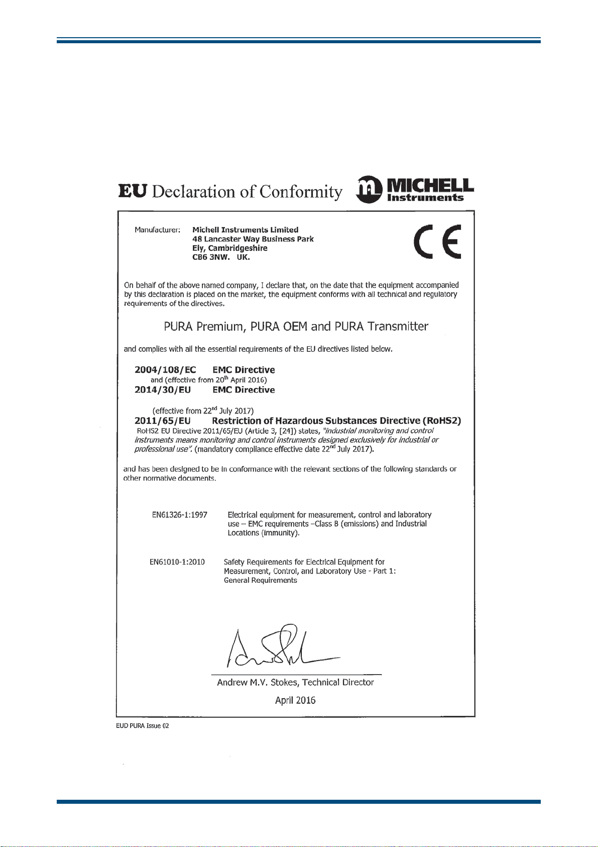
EU Declaration of Conformity
NOTE: The PURA I.S. product incorporates the ATEX/IECEx/CSA/FM approved Easidew I.S.
product and it is the Hazardous Area Certifi cation for the Easidew I.S. that provides the necessary
approvals for the PURA I.S.
Michell Instruments vii 97306 Issue 1.1, March 2016
Page 8
Pura Hazardous Area Transmitter 2-Wire User’s Manual
Abbreviations
The following abbreviations are used in this Manual:
AC alternating current
atm pressure unit (atmosphere)
barg pressure unit (=100 kP or 0.987 atm)
ºC degrees Celsius
ºF degrees Fahrenheit
DC direct current
ft foot (feet)
g gram(s)
Hz Hertz
“ inch(es)
kg kilogram(s)
lb pound
Nl/min normal liters per minute
m meter(s)
mA milliampere
max maximum
min minute(s)
mm millimeter(s)
MPa megapascal (Pascals x106)
m/sec meters per second
Nm Newton meter
ppmV parts per million (by volume)
RS232 serial data transmission standard
Rx receive
scfh standard cubic feet per hour
scfs standard cubic feet per second
sec second(s)
temp temperature
Tx transmit
V Volts
Ω Ohms
Warnings
The following general warnings listed below are applicable to this instrument. They are repeated in the text in
the appropriate locations.
Where this hazard warning symbol appears in the following
sections it is used to indicate areas where potentially
hazardous operations need to be carried out.
97306 Issue 1.1, March 2016 viii Michell Instruments
Page 9

Pura Hazardous Area Transmitter 2-Wire User’s Manual
Recycling Policy
Michell Instruments is concerned with the protection of the environment. It is our commitment to reduce
and eliminate from our operations, wherever possible, the use of substances which may be harmful to the
environment. Similarly, we are increasingly using recyclable and/or recycled material in our business and
products wherever it is practical to do so.
The product that you have purchased may contain recyclable and/or recycled parts and we will be happy to
provide you with information on these components if required.
WEEE And RoHS Compliance
The Waste Electronic and Electrical Equipment (WEEE) Directive, and the Restriction of Hazardous Substances
(RoHS) Directive place rules upon European manufacturers of electrical and electronic equipment. The
directive’s aim is to reduce the impact that electronic devices have on the environment.
Michell products are currently exempt from the RoHS directive, however all future products will be developed
entirely using compliant materials. Furthermore, Michell is taking active steps to remove non-compliant
materials and components from existing products wherever possible.
Michell is in full compliance with the WEEE Directive (Registration No. WEE/JB0235YW). Customers may be
required to return certain instruments for treatment at the end of their working life.
June 2010
Calibration Facilities
Michell Instruments’ calibration facilities are among the most sophisticated in the world and have been
recognized for their excellence.
Traceability to the National Physical Laboratory (NPL) UK is achieved through our UKAS Accreditation
(Number 0179). This covers dew point over the range -90 to +90°C (-130 to +194°F) and also Relative
Humidity.
Dew-point calibrations are also traceable to the National Institute for Standards & Technology (NIST) USA over
the range -75 to +20°C (-103 to +68°F).
NOTE: Standard traceable calibration certifi cates for instruments and sensors are not issued
under our UKAS accreditation. UKAS certifi cates are usually to special order and are clearly
identifi ed.
Manufacturing Quality
Michell Instruments is registered with the British Standards Institute for Quality Assurance to:
BS EN ISO 9001: 2008
Rigorous procedures are performed at every stage of production to ensure that the materials of construction,
manufacturing, calibration and fi nal test procedures meet the requirements laid down by our BSI approved
Quality System.
Please contact Michell Instruments if the product does not arrive in perfect working order.
Michell Instruments ix 97306 Issue 1.1, March 2016
Page 10

Pura Hazardous Area Transmitter 2-Wire User’s Manual
Warranty
Unless otherwise agreed, the Supplier warrants that, as from the date of delivery for a period of 12 months,
the goods and all their component parts, where applicable, are free from any defects in design, workmanship,
construction or materials.
The Supplier warrants that the services undertaken shall be performed using reasonable skill and care, and of
a quality conforming to generally accepted industry standards and practices.
Except as expressly stated all warranties, whether express or implied, by operation of law or otherwise, are
hereby excluded in relation to the goods and services to be provided by the Supplier.
All warranty services are provided on a return to base basis. Any transportation costs for the return of a
warranty claim shall reside with the Customer.
Return Policy
If a Michell Instruments’ product malfunctions within the warranty period, the following procedure must be
completed:
1. Notify a Michell Instruments’ representative, giving full details of the problem,
the model variant and the serial number of the product.
2. If the nature of the problem indicates the need for factory service then the
instrument should be returned to Michell Instruments, carriage prepaid,
preferably in the original packaging, with a full description of the fault
and the customer contact information.
3. Upon receipt, Michell Instruments will evaluate the product to determine the
cause of the malfunction. Then, one of the following courses of action will
be taken:
• If the fault is covered under the terms of the warranty, the
instrument will be repaired at no cost to the owner and returned.
• If Michell Instruments determines that the fault is not covered
under the terms of the warranty, or if the warranty has expired,
an estimate for the cost of the repairs, at standard rates, will be
provided. Upon receipt of the owner’s approval to proceed, the
product will be repaired and returned.
97306 Issue 1.1, March 2016 x Michell Instruments
Page 11

Pura Hazardous Area Transmitter 2-Wire User’s Manual
1 INTRODUCTION
The Pura Series of transmitters has been manufactured, tested and calibrated to the highest available standards
and should arrive in perfect working order, ready for installation into a gas measurement application. If there
are any questions about the transmitter or how to install it, not detailed in this Manual, contact your local
representative. Refer to Appendix D for details of Michell Instruments’ worldwide offi ces’ contact information.
The Pura is a continuous, on line instrument for the measurement of moisture content in air and other gases
over an operating range of -120°C to -40°C dew point. The Pura operates as a 4-20 mA or digital transmitter
providing an output to an external control or monitoring device, and is factory set over the range -120°C to
-40°C dew point. However, the range can be adjusted using the Pura application software available as a free
download via the website: www.michell.com.
2 DESCRIPTION
Their key features of the Pura Trransmitter are:
• up to ±1°C dp accuracy
• 0.5ºCdp (0.9ºFdp) repeatability
• 2-wire connection - linear 4 –20 mA signal
• Operating pressure range - up to 24 MPa (240 barg / 3480 psig)
• Operating range - 120 to -40°C dew point
• Moisture content ppmV
• Powered by any DC source from 12 to 28 V
Michell Instruments 1 97306 Issue 1.1, March 2016
Page 12

Pura Hazardous Area Transmitter 2-Wire User’s Manual
3 PREPARATION FOR USE
On delivery, check that all the following standard components are present in the packing box:
Pura Transmitter Pura OEM Pura Premium
Calibration Certifi cate Calibration Certifi cate Calibration Certifi cate
Transmitter Connector Leak Test Certifi cate Leak Test Certifi cate
Connector Gasket Transmitter Connector Transmitter Connector
97306 User’s Manual Connector Gasket Connector Gasket
97306 User’s Manual 97306 User’s Manual
The recommended gas fl ow rate, when mounted in the system, is 1 to 10 Nl/min (2.1 to 21.2 scfh) (5 Nl/min
(10.6 scfh) optimum).
97306 Issue 1.1, March 2016 2 Michell Instruments
Page 13

Pura Hazardous Area Transmitter 2-Wire User’s Manual
4 SENSOR INSTALLATION
4.1 Installing the Sensor
The effective operation of the Pura I.S. Transmitter, in a fl owing gas environment, relies on the sensor being
installed directly into the gas stream or by having a fully representative gas sample directed over the sensor
measurement surface. Where possible avoid installing the sensor in a “dead” or unswept volume.
Michell Instruments recommends the use of Swagelok® retained gasket assemblies, containing silver plated,
stainless steel ¼” VCR gaskets, when connecting the Pura I.S. Transmitter into a gas line. The distance
between the inlet and outlet gas connection ports is set at a pitch of 120mm.
• Install the sealing gasket onto the VCR connections on either the Pura I.S.
Transmitter or the connecting gas lines. Ensure that the Pura I.S. Transmitter
is offered into the gas line with reference to the gas fl ow direction and the
inlet port as indicated on the Pura I.S. Transmitter body.
• Tighten the female nut fi rmly - fi nger tight.
• While holding the Pura I.S. Transmitter stationary with a spanner/wrench,
tighten the gas line nut 1/8 (one eighth) of a turn using a second spanner.
CAUTION: Over-tightening the nuts can cause
irrecoverable damage to the seals and seatings.
• Repeat this operation on the remaining gas connection port.
h
150mm
6”
¼” VCR
CONNECTION
g
h
20mm
0.8”
g
h
g
h
Ø35mm
1.4”
g
28mm
1.1”
g
g
120mm
20mm
0.8”
4.7”
g
h
h
g
2 OFF HOLES
M4 X 7 DEEP
Figure 4.1 Pura Premium & Pura OEM Dimensional Drawings
Michell Instruments 3 97306 Issue 1.1, March 2016
Page 14

Pura Hazardous Area Transmitter 2-Wire User’s Manual
4.2 Pura Transmitter (Sensor Only Version) Installation
The Pura Transmitter (Sensor only version) is supplied fi tted with a protective guard. It is recommended that
this guard be removed before installation, as, although clean, it is not manufactured to the same high level
of surface fi nish as the sensor itself; its intended purpose is only to protect the measurement element of the
sensor during handling.
Any use of the transmitter with the guard attached will not affect the sensor accuracy but may induce an
extended measurement response and provide an opportunity for moisture entrapment points, creating
potentially false measurement of the sample.
It is recommended that the guard remains fi tted until the transmitter is completely ready to be installed into
the point of measurement. Once removed, the guard should be retained and reinstalled as protection, should
the transmitter be removed from its point of installation e.g. for re-calibration.
CAUTION: Care should be exercised when withdrawing the guard
from the transmitter ensuring no contact is made with the sensor’s
measurement surface; doing so can affect the performance of the sensor.
Similarly, when inserting the sensor into the point of measurement,
avoid contact with the sensor measurement surface.
The Pura transmitter installation interface is made by way of a ½” VCR sealing face on the body of the
transmitter. Effective installation can only be completed by mating this sealing face with a similar sealing face
and via the use of a metal gasket.
Michell Instruments recommend the use of Swagelok® retained gasket assemblies, containing silver plated,
stainless steel ½” VCR gaskets, when connecting the Pura into a measurement point. Gaskets are available
from Michell, part no. 20904.
97306 Issue 1.1, March 2016 4 Michell Instruments
Page 15

Installation Instructions
• Install the sealing gasket onto the transmitter body of the Pura.
• Tighten the joining female nut fi rmly fi nger tight.
• Hold the Pura transmitter stationary with a spanner/wrench and tighten the
gas line nut 1/8 (one eighth) of a turn using a second spanner/wrench.
Pura Hazardous Area Transmitter 2-Wire User’s Manual
Pura Transmitter
CAUTION: Over tightening the nuts can cause
irrecoverable damage to the seals and seatings.
45mm
g
1.8”
h
h
105mm
4.1”
½” VCR
CONNECTION
h
h
h
27mm
1.1”
g
h
h
31mm
h
1.2”
6mm
0.23”
h
Figure 4.2 Pura Sensor Dimensional Drawing
Michell Instruments 5 97306 Issue 1.1, March 2016
Page 16

Pura Hazardous Area Transmitter 2-Wire User’s Manual
4.3 Transmitter Cable
Cable connection to the Pura I.S. Transmitter is made via the removable connector.
When removing the central screw ensure that the small sealing
O-ring is retained on the screw and present during re-installation.
Removing the central screw enables the connector terminal block to be removed from the outer housing by
using a small screwdriver to prise it off.
Figure 4.3 Terminal block Removal
When reinstalling the connector, and to ensure that full ingress protection is achieved, the securing screw
must be tightened to a minimum torque setting of 3.4Nm (2.5 lbs/in) and the sensor cable used must have a
minimum diameter of 4.6mm (0.2”).
97306 Issue 1.1, March 2016 6 Michell Instruments
Page 17

Pura Hazardous Area Transmitter 2-Wire User’s Manual
4.4 Preparation of the Sensor Cable
It is essential that, to comply with Hazardous Area
Certifi cation of the product, the crimps supplied must be
fi tted onto any cable installed into the connector.
NOTE: Figures 4.4 to 4.7 shown below, should be followed in detail. The crimps should be applied
such that there is no possibility of a conductor strand of a core becoming free.
When the crimp is made it should have a minimum of 2 positions of crimping. After the crimp is made it should
be trimmed to a length of 5mm (see
block ensure they are fully inserted, as shown in
Figure 4.4 Bare wires
Figure 4.6)
. When the crimps are installed into the connector terminal
Figure 4.7
Figure 4.5
, before tightening the terminal clamping screw.
Crimped wires
mm
10
When all wire connections are made, ensure that there is a minimum clearance distance and a minimum
creepage distance in air of 2mm (0.8”) between each terminal.
Michell Instruments 7 97306 Issue 1.1, March 2016
Figure 4.6 Cut to 5mm
Figure 4.7 Connection to Pura I.S.TX
Page 18

Pura Hazardous Area Transmitter 2-Wire User’s Manual
The diagram below shows the identity of the connector terminals:
Supply
4-20 mA
h
PIN 1
PIN 3
h
(GND)
Screen/Shield
Optional
Figure 4.8 Rear of connector terminal block
Always connect the 4-20 mA return signal to a suitable load (see
Figure 4.9)
transmitter may be damaged if allowed to operate for prolonged periods.
3
1
before the power is applied. Without this connection the
+
Max Load
250R @ 12V
500R @ 24V
Supply
12V Min
28V Max
GALVANIC ISOLATION INTERFACE
X
X
SAFE AREA
(+)
(-)
KFD2-STC4-Ex1 H
KFD0-CS-Ex2.50p
KFD2-CR-Ex1.20200
KFD2-CR-Ex1.30200
KFD0-CS-Ex1.50P
MTL5041
MTL5040
MTL5541
+
-
4-20 mA
LOAD
+VS (20 - 35 V DC)
VS -
DEW-POINT
TRANSMITTER
CERTIFICATION No’s:
Baseefa06ATEX0330X
IECEx BAS 06.0090X
HAZARDOUS AREA
TRANSMITTER VERSION
TERMINAL NUMBER
3
1
X
(+)
(RETURN)
X
Figure 4.9 Electrical Connections
97306 Issue 1.1, March 2016 8 Michell Instruments
Page 19

Pura Hazardous Area Transmitter 2-Wire User’s Manual
4.5 Installation in Hazardous Areas
The Transmitter is certifi ed intrinsically safe for use in hazardous areas, by Notifi ed Body Baseefa Ltd. The
instrument conforms to the ATEX & IECEx standards with certifi cation code:
II 1 G Ex ia IIC T4 (-20°C ≤ Ta ≤ +70°C)
The Transmitter is also certifi ed for use in Hazardous Areas by FM Approvals and CSA, with certifi cation code:
IS / I / 1 / ABCD / T4 Ta = +70°C, Entity Ex90385, IP66
Also see Appendix B for more information on certifi cation.
Before using the Transmitter in any hazardous environment, ensure that you are fully familiar with the relevant
standards relating to the certifi cation of this instrument; and also with the further information relating to
intrinsically safe apparatus to be found in standard EN 60079-14:1997 or equivalent, and up-to-date codes of
practice in the country of installation.
The Transmitter must be installed using a specifi ed GALVANICALLY ISOLATED INTERFACE unit as shown in the
system drawings in Appendix C
Installation of the Transmitter
Appendix C in order to comply with the Intrinsic Safety Certifi cation.
MUST
be as per the system drawings in
5 WHICH GASES TO MEASURE?
The Pura Hygrometer is suitable for measurement of the moisture content of a wide variety of gases. In
general, if the gas (in conjunction with water vapor) is not corrosive to ceramics or base metals then it will be
suitable for measurement by the Pura Hygrometer.
6 MAINTENANCE
Routine maintenance of the Pura I.S. Transmitter is confi ned to regular re-calibration. This work can only be
done by exposure of the Pura I.S. Transmitter to sample gases of known moisture content. Calibration services
traceable to the National Physical Laboratory (UK) and the National Institute of Standards and Technology
(USA) are provided by Michell Instruments. In most applications, annual re-calibration ensures that the
stated accuracy of the Pura I.S. Transmitter is maintained. Pura I.S. Transmitters are fully interchangeable and
interchangeability is not affected by cable length; therefore, this method of maintaining calibration can be used
for all Pura I.S. Transmitter installations. For applications where it is not required for continuous operation,
re-calibration of the Pura I.S. Transmitter can be achieved by return of the complete instrument to Michell
Instruments.
Michell Instruments 9 97306 Issue 1.1, March 2016
Page 20

Pura Hazardous Area Transmitter 2-Wire User’s Manual
7 FAULT CONDITIONS
7.1 Sampling Hints
Be Sure the Sample is Representative of the Gas Under Test
The sample point should be as close to the critical measurement point as possible. Also, never sample from
the bottom of a pipe (see
sensing element.
Figure 7.1),
as entrained gas or particulate contamination may be drawn into the
Minimize Dead Space in Sample Lines
Dead space (see
measurement errors, as a result of the trapped moisture being released into the passing sample and causing
an increase in partial vapor pressure.
Remove Any Particulate Matter from the Sample
Particulate matter at high velocity can damage the sensing element and similarly at low velocity, they may
“blind” the sensing element and reduce its response speed. If particulate, such as degraded desiccant, pipe
scale or rust is present in the sample, use an in-line fi lter.
Figure 7.2)
Figure 7.1 Installation location
causes moisture entrapment points, increased system response times and
Figure 7.2 Indication of dead space
Use High Quality Sample Tube and Fittings
Michell Instruments recommends that, wherever possible, stainless steel tubing and fi ttings should be used.
This is particularly important at low dew points since other materials have hygroscopic characteristics and
adsorb moisture on the tube walls, slowing down response and, in extreme circumstances, giving false readings.
97306 Issue 1.1, March 2016 10 Michell Instruments
Page 21

Pura Hazardous Area Transmitter 2-Wire User’s Manual
Appendix A
Technical Specifi cations
Michell Instruments 11 97306 Issue 1.1, March 2016
Page 22

Pura Hazardous Area Transmitter 2-Wire User’s Manual
Appendix A Technical Specifi cations
Transmitter
Measurement Range (dew point) -120 to -40°C (-184 to -40°F) dew point
Accuracy (dew point) ±1°C from -40 up to -60°C
±2°C from -60 up to -100°C
±4°C from -100 up to -120°C (estimated)
Repeatability 0.5°C (0.9°F) dew point
Electrical Output/Input
Output Signal
Output
Output Range
Supply Voltage 12-28 V DC
Load Resistance Max 250 Ω @ 12 V (500 Ω @ 24 V)
Current Consumption 23 mA
Supply Voltage Infl uence
4-20 mA (2-wire connection, current source)
User-confi gurable over range
Dew point, moisture content for ppmV, ppb
Dew point: -120 to -40°C (-184 to -40°F)
±0.005% RH/V
v
Operating Conditions
Operating Humidity 0–100% RH
Operating Temperature -40 to +60°C (-40 to +140°F)
Operating Pressure 24 MPa (240 barg / 3480 psig) max
Flow Rate
1 to 10 Nl/min (2.1 to 21.2 scfh)
(5 Nl/min (10.6 scfh) optimum)
Mechanical Specifi cation
Hazardous Area Certifi cates ATEX - II 1 G Ex ia IIC T4 (-20°C ≤ Ta ≤ +70°C)
FM - IS / I / 1 / ABCD / T4 Ta = +70°C
CSA - IS Class 1 Div 1 Groups ABCD T4
IECEx - Ex ia IIC T4 (-20°C ≤ Ta ≤ +70°C)
Ingress Protection IP66 in accordance with standard BS EN 60529:1992, and NEMA 4 in
protection accordance with standard NEMA 250-2003
Housing Material Stainless steel
Mounting Thread
Weight Premium and OEM versions: 450g (15.87oz)
Interchangeability Fully interchangeable transmitter
Electrical Connections Screw terminal
Fault Conditions
(factory programmed)
Approved Galvanic Isolators
Approved Galvanic Isolators
¼” male VCR connection
½” male VCR connection
Pura Sensor version: 180g (6.34oz)
Condition
Sensor fault
Under-range dew point
Over-range dew point
KFD2-CR-Ex1.20200 / KFD2-CR-Ex1.30200
KFD0-CS-Ex1.50P / KFD0-CS-Ex2.50P
KFD2-STC4-Ex1 H / MTL5041, MTL5040, MTL5541
KFD2-CR-Ex1.20200 / KFD2-CR-Ex1.30200
KFD0-CS-Ex1.50P / KFD0-CS-Ex2.50P
KFD2-STC4-Ex1 H / MTL5041, MTL5040, MTL5541
Output
23 mA
4 mA
20 mA
97306 Issue 1.1, March 2016 12 Michell Instruments
Page 23

Pura Hazardous Area Transmitter 2-Wire User’s Manual
Appendix B
Hazardous Area Certifi cation
Michell Instruments 13 97306 Issue 1.1, March 2016
Page 24

Pura Hazardous Area Transmitter 2-Wire User’s Manual
Appendix B Hazardous Area Certifi cation
NOTE: The PURA I.S. product incorporates the ATEX/IECEx/CSA/FM approved Easidew I.S.
product and it is the Hazardous Area Certifi cation for the Easidew I.S. that provides the necessary
approvals for the PURA I.S.
The Transmitter is certifi ed compliant to the ATEX Directive (94/9/EC), and IECEx for safe use within a hazardous
area and has been assessed so by Baseefa Ltd (Notifi ed Body 1180).
This product uses the Easidew TX I.S. PCB assembly and therefore conforms to the Standards EN 600790:2004, EN60079-11:2007, IEC60079-0:2004, IEC60079-11:1999 and is attributed with a product certifi cation
code:
II 1 G Ex ia IIC T4 (-20°C ≤ Ta ≤ +70°C)
ATEX Certifi cate Number : Baseefa06ATEX0330X
ATEX System Certifi cate Number: Baseefa07Y0027
IEC Certifi cate Number: IECEx BAS 06.0090X
It is also certifi ed for use in Hazardous Areas by FM Approvals and CSA, with certifi cation code:
IS / I / 1 / ABCD / T4 Ta = +70°C, Entity Ex90385, IP66
FM Certifi cate Number: 3030238
CSA Certifi cate Number: 2013218
These certifi cates can be viewed or downloaded from our website (under Easidew TX I.S.) at: http://www.
michell.com/accreditations
B1 Terminal Parameters
Ui = 28V
Ii = 93mA
Pi = 651mW
Ci = 37nF
Li = 0
B2 Special Conditions of Use
Wiring to the free socket must be made via crimped connectors such that all strands of the wires are retained
securely by the crimp.
The plastic plug & socket provide potential for electrostatic discharge. Do not rub with a dry cloth and do not
clean with solvents.
The Transmitter does not withstand the 500 V AC insulation test to frame. This must be taken into account
when installing the equipment.
97306 Issue 1.1, March 2016 14 Michell Instruments
Page 25

Pura Hazardous Area Transmitter 2-Wire User’s Manual
Appendix C
System Drawings
Michell Instruments 15 97306 Issue 1.1, March 2016
Page 26

Pura Hazardous Area Transmitter 2-Wire User’s Manual
Appendix C System Drawings
NOTE: The Pura I.S. sensor uses the Easidew I.S. PCB assembly and therefore this certifi cation
is valid for this instrument.
C1 Baseefa Approved System Drawing
97306 Issue 1.1, March 2016 16 Michell Instruments
Page 27

Pura Hazardous Area Transmitter 2-Wire User’s Manual
C2 FM Approved System Drawing
Ex90385
EASIDEW I.S. DEWPOINT TRANSMITTER
FM SYSTEM DRAWING
A3
SHEET 1 OF 1
MICHELL INSTRUMENTS LTD. CAMBRIDGE ©
USED ON
SIGN
DATE
MOD. No.ISSUE
02 CERT ISS 23/12/08 IMA
DRAWING NUMBER
05 11081 06/04/11 IMA
SCALE
UNITS
DRAWING
+VS (20 TO 35V DC)
LOAD
4/20mA
+
KFD2-CR-Ex1.20200
BAS 00 ATEX 7164
000
VS -
+0.1
-
UNLESS OTHERWISE STATED
TOLERANCES:
3rd ANGLE
PROJECTION
KFD2-CR-Ex1.30200
BAS 00 ATEX 7164
000
KFD0-CS-Ex1.50P
BAS 98 ATEX 7343
000
MTL5041
BAS 01 ATEX 7155
000
MTL5040
BAS 98 ATEX 2227
000
KFDO-CS-Ex2.50P
BAS98ATEX7343
01 CERT ISS 16/07/07 IMA
03 CERT ISS 21/01/09 IMA
04 CERT ISS 24/03/09 IMA
NTS
mm
-0.0
ANGLES: ±0.5°
HOLE Ø:
5
FINISH
0 DEC. PLACE: ± 0.
1 DEC. PLACE: ± 0.2
2 DEC. PLACE: ± 0.1
DIMENSIONS:
MATERIAL
TITLE
(-)
TERMINAL NUMBER
EASIDEW
EASIDEW
(+)
APPROVEDCHECKED
DATEDATE
(+)
(RETURN)
3
2
4
PRO I.S.
1
3
I.S.
DEWPOINT
TRANSMITTER
CERTIFICATION No's:
Baseefa06ATEX0330X
IECEX BAS 06.0090X
WITHOUT THE CONSENT OF MICHELL INSTRUMENTS.
AND MUST NOT BE COPIED NOR DISCLOSED TO A THIRD PARTY
THIS DOCUMENT IS T HE P ROPERTY OF MICHELL INSTRUMENTS LTD.
10/03/06
MSB
DRAWN
DATE
4 Inches
100mm
ȍ
ȍ
ȍ
ȝ
ȝ
ȝ
54 H/
ȝ
435 H/
217 H/
33mH
4.2mH
12.6 mH
ȝ
ȝ
46 nF
613 nF
2.11 F
NON-HAZARDOUS LOCATION
TRANSMITTER VERSION
HAZARDOUS LOCATION
CLASS 1, DIVISION 1, GROUPS A,B,C, & D
DCAB
THE CAPACITANCE AND EITHER THE INDUCTANCE OR THE INDUCTANCE TO RESISTANCE RATIO
(L/R) OF THE CABLE MUST NOT EXCEED THE FOLLOWING VALUES:
THE ISOLATION OF THE SIGNAL WIRES WITH THE EASIDEW DISCONNECTED, MUST BE ABLE TO
GROUP CAPACITANCE INDUCTANCE OR L/R RATIO
( F) (mH) ( H/ohm)
WITHSTAND A 500V AC INSULATION TEST.
THE CAPACITANCE AND THE INDUCTANCE OF TEH HAZARDOUS AREA CABLES MUST NOT
USE, i.e. ANSI/ISARP12.6(INSTALLATION OF INTRINSICALLY SAFE SYSTEMS FOR HAZARDOUS
EXCEED THE VALUES GIVEN IN TABLE 1.
[CLASSIFIED] LOCATIONS) AND THE NATIONAL ELECTRICAL CODE ANSI/NFPA 70.
MICHELL INSTRUMENTS LTD. 01/11/05 DOF03
THE INSTALLATION MUST COMPLY WITH THE INSTALLATION PRACTICES OF THE COUNTRY OF
Michell Instruments 17 97306 Issue 1.1, March 2016
Page 28

Pura Hazardous Area Transmitter 2-Wire User’s Manual
C3 CSA Approved System Drawing
97306 Issue 1.1, March 2016 18 Michell Instruments
Page 29

Pura Hazardous Area Transmitter 2-Wire User’s Manual
Appendix D
List of Worldwide Michell
Instruments’ Offi ces
Michell Instruments 19 97306 Issue 1.1, March 2016
Page 30

Pura Hazardous Area Transmitter 2-Wire User’s Manual
Appendix D List of Worldwide Michell Instruments’ Offi ces
Asia
Michell Asia
PO Box 3149
Joondalup
WA 6027
Australia
Tel: +61 893 046587
E-mail: au.info@michell.com
Web: www.michell.com/au
China
Michell Instruments (Shanghai) Ltd
Room 1007, Qilai Building
889 Yishan Road
Shanghai, 200233
P R China
Tel: +86 21 5401 2255
Fax: +86 21 5401 2085
E-mail: cn.info@michell.com
Web: www.michell.com/cn
Germany, Austria, Switzerland
Michell Instruments GmbH
Industriestrasse 27
D-61381 Friedrichsdorf
Germany
Tel: +49 6172 591700
Fax: +49 6172 591799
E-mail: de.info@michell.com
Web: www.michell.com/de
Benelux
Michell Instruments Benelux BV
Krombraak 11
4906 CR Oosterhout
The Netherlands
Tel: +31 162 680 471
Fax: +31 162 437 566
E-mail: nl.info@michell.com
Web:
www.michell.com/nl
France
Michell Instruments SAS
2-4, rue Jean Desparmet
69008 Lyon
France
Tel: +33 437 53 88 20
Fax: +33 437 53 88 21
E-mail: fr.info@michell.com
Web: www.michell.com/fr
Italy
Michell Italia Srl
Via Capecelatro, 10
20148 Milano
Italy
Tel: +39 02 4047194
Fax: + 39 02 40010565
E-mail: it.info@michell.com
Web: www.michell.com/it
Japan
Michell Japan KK
Musashino Center Building
1-19-18 Nakacho, Musashino
Tokyo 180-0006
Japan
Tel: +81 422 502600
Fax: +81 422 521700
E-mail: info@michell-japan.co.jp
Web: www.michell-japan.co.jp
North America
Michell Instruments Inc
319 Newburyport Turnpike, Suite 207
Rowley, MA 01969
USA
Tel: +01 978 484 0005
Fax: +01 978 843 7669
E-mail: us.info@michell.com
Web: www.michell.com/us
Middle East
Michell Instruments Middle East
P-06, #097
Sharjah Airport Int’l free zone
Sharjah,
United Arab Emirates
Tel: +971 6 5575028
Fax: +971 6 5575029
E-mail: me.info@michell.com
United Kingdom
Michell Instruments Ltd
48 Lancaster Way Business Park
Ely, CB6 3NW
Cambridgeshire
England
Tel: +44 1353 658000
Fax: +44 1353 658199
E-mail: info@michell.com
Web: www.michell.com/uk
97306 Issue 1.1, March 2016 20 Michell Instruments
Page 31

NOTES:
Pura Hazardous Area Transmitter 2-Wire User’s Manual
Michell Instruments 21 97306 Issue 1.1, March 2016
Page 32

http://www.michell.com
 Loading...