

Page 1
PSD2
Pressure Swing Dryer
User’s Manual
97031 Issue 13.1
September 2018
Page 2
Please fi ll out the form(s) below for each instrument that has been purchased.
Use this information when contacting Michell Instruments for service purposes.
Instrument
Code
Serial Number
Invoice Date
Location of Instrument
Tag No
Instrument
Code
Serial Number
Invoice Date
Location of Instrument
Tag No
Instrument
Code
Serial Number
Invoice Date
Location of Instrument
Tag No
Page 3
PSD2
For Michell Instruments' contact information please go to
www.michell.com
© 2018 Michell Instruments
This document is the property of Michell Instruments Ltd. and may not be copied or
otherwise reproduced, communicated in any way to third parties, nor stored in any Data
Processing System without the express written authorization of Michell Instruments Ltd.
Page 4

PSD2 User’s Manual
Contents
Safety ................................................................................................................................ v
Electrical Safety ........................................................................................................... v
Pressure Safety ............................................................................................................ v
Toxic Materials ............................................................................................................. v
Repair and Maintenance ............................................................................................... v
Safety Conformity ........................................................................................................ v
Abbreviations ......................................................................................................................vi
Warnings ............................................................................................................................vi
1 INTRODUCTION ................................................................................................1
1.1 Overview ........................................................................................................... 1
1.2 Operating Principle .............................................................................................1
2 INSTALLATION ..................................................................................................2
2.1 Installing the Dryer ............................................................................................. 2
2.2 Electrical Connections .........................................................................................2
2.3 Gas Connections ................................................................................................. 2
3 OPERATION ......................................................................................................3
3.1 Operating the Dryer ............................................................................................ 3
4 MAINTENANCE ..................................................................................................4
4.1 Maintaining the Dryer ........................................................................................4
4.1.1 Desiccant Change .........................................................................................4
4.1.2 Adjusting the Purge Flow ............................................................................... 6
4.2 Fault Diagnosis ................................................................................................... 8
4.2.2 Flow, Pressure and Timing Calibration ............................................................8
Figures
Figure 1 System Layout Drawing ............................................................................13
Figure 2 Schematic Flow Drawing ...........................................................................14
Appendices
Appendix A Technical Specifi cations ..............................................................................11
Appendix B System Drawings .......................................................................................13
B.1 System Layout Drawing ................................................................13
B.2 Schematic Flow Drawing ..............................................................14
Appendix C Quality, Recycling, Compliance & Warranty Information ................................16
Appendix D Return Document & Decontamination Declaration ........................................18
iv 97031 Issue 13, July 2018
Page 5

PSD2 User’s Manual
Safety
The manufacturer has designed this equipment to be safe when operated using the procedures
detailed in this manual. The user must not use this equipment for any other purpose than that
stated. Do not apply values greater than the maximum value stated.
This manual contains operating and safety instructions, which must be followed to ensure the safe
operation and to maintain the equipment in a safe condition. The safety instructions are either
warnings or cautions issued to protect the user and the equipment from injury or damage. Use
competent personnel using good engineering practice for all procedures in this manual.
Electrical Safety
The instrument is designed to be completely safe when used with options and accessories supplied
by the manufacturer for use with the instrument.
Pressure Safety
DO NOT permit pressures greater than the safe working pressure to be applied to the instrument.
The specifi ed safe working pressure is 5 to 7 barg (70 to 100 psig).
Toxic Materials
The use of hazardous materials in the construction of this instrument has been minimized. During
normal operation it is not possible for the user to come into contact with any hazardous substance
which might be employed in the construction of the instrument. Care should, however, be exercised
during maintenance and the disposal of certain parts.
Repair and Maintenance
The instrument must be maintained either by the manufacturer or an accredited service agent. Refer
to www.michell.com for details of Michell Instruments’ worldwide offi ces contact information.
Safety Conformity
This product meets the essential protection requirements of the relevant EU directives. Further
details of applied standards may be found in the product specifi cation.
Michell Instruments v
Page 6

Abbreviations
The following abbreviations are used in this manual:
AC alternating current
atm pressure unit (atmosphere)
bar pressure unit (=100 kP or 0.987 atm)
°C degrees Celsius
°F degrees Fahrenheit
dp dew point
kg kilogram
Hz Hertz
lb pound
l/min liters per minute
max maximum
mm millimeter
ppm
parts per million (by volume)
V
ppb
parts per billion (by volume)
V
scfh standard cubic feet per hour
V Volts
" inch(es)
% percentage
PSD2 User’s Manual
Warnings
The following general warning listed below is applicable to this instrument. It is repeated
in the text in the appropriate locations.
!
Where this hazard warning symbol appears in the following
sections it is used to indicate areas where potentially hazardous
operations need to be carried out.
vi 97031 Issue 13, July 2018
Page 7

PSD2 User’s Manual
1 INTRODUCTION
1.1 Overview
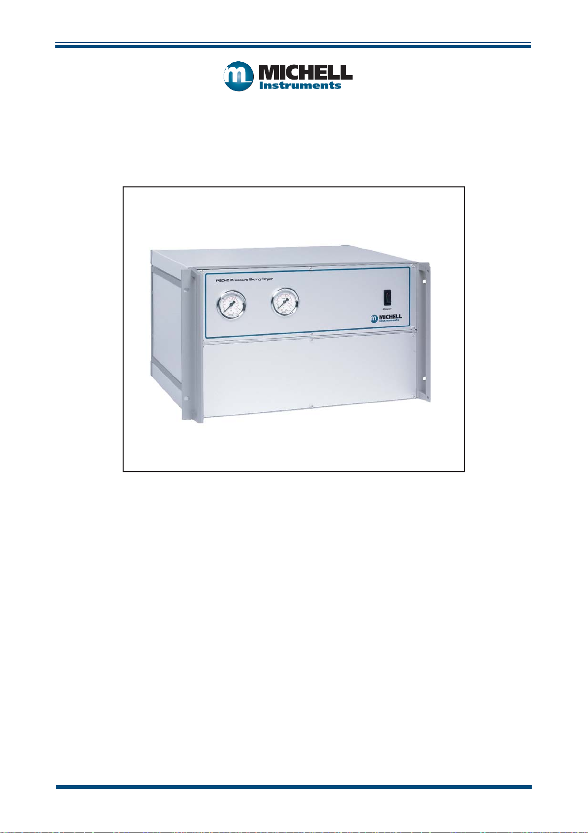
The Michell PSD2 is a Pressure Swing Dryer in a compact rack mounting unit designed
to remove moisture from compressed air down to trace levels of less than 1 part per
million by volume.
The dryer operates by pressure swing regeneration of a desiccant column. Design is
such that, with 2 columns operating in rotation, a constant fl ow of very dry air (or other
inert gas) can be produced for long periods without maintenance.
Heat is not supplied to the desiccant making the unit energy effi cient and extremely
reliable with the typical lifetime of the desiccant being 5 years.
1.2 Operating Principle
INTRODUCTION
The supply pressure is regulated by PR1, and indicated by either gauge PG1 or PG2,
depending which column is active at that moment in time.
The gas then passes through the solenoid valves (SV1 & SV2), which direct it to the
appropriate desiccant column (DC1 or DC2).
The desiccant columns are fi lled with 4 Ångström molecular sieve. The column capacity
is designed so that, as the molecular sieve absorbs water from the gas, the moisture
content at the outlet of the cylinder is reduced to <1ppmV. This output is achievable
regardless of the moisture content of the gas source. the only stipulation is that it must
not contain liquid water.
The dried gas then passes through the non-return valve (NRV1) before reaching the
outlet port.
The life expectancy of the molecular sieve is preserved by continual regeneration of the
active column (purging of accumulated moisture). At the beginning of the regeneration
cycle the bulk of the moisture is removed by rapidly reducing the pressure in the
column, which desorbs moisture from the molecular sieve surface. Following this, the
remainder of the moisture is removed by fl owing a small proportion of the dried gas
from the active column.
Once this cycle is complete, the system switches columns, and begins the cycle again.
This regeneration process operates on 10 minute cycles, to provide uninterrupted dry
gas output.
Michell Instruments 1
Page 8

INSTALLATION
2 INSTALLATION
The PSD2 is supplied with a full accessory package. Please check that you have received
all the items listed on the Packing Check List.
The factory set power supply voltage is indicated on the yellow label located on the rear
panel of the unit. The power supply voltage setting cannot be changed by the user as
this involves replacing internal electro-mechanical parts. Contact Michell Instruments’
Customer Service Department (contact details at www.michell.com) if a change is
needed.
2.1 Installing the Dryer
The PSD2 requires an operating environment of 0 to +50°C (+32 to +122°F), 0 to 90%
RH. Refer to Appendix B for outline dimensions.
The PSD2 case is designed for 19” 6U rack mounting. However, it can be used as a
bench mounted device without any special preparation. When rack mounting, simply
screw the unit front panel to the front of the rack using 4 M6 X 15mm screws and plastic
inserts.
PSD2 User’s Manual
NOTE: A minimum depth behind the PSD2 front panel of 48cm (18.9”) is
required for the unit, pipes and wiring.
2.2 Electrical Connections
Either 220/240 V AC, 50Hz or 100/20 V AC, 60Hz power supply is required to operate
this instrument. Refer to the yellow label located on the rear panel of the unit for the
correct supply voltage required.
The power supply connection is via the 3-pin IEC plug located on the rear panel of
the unit. A 3-core power cable is provided, the free end of which should be wired to a
suitable earthed plug or directly via a fused power spur.
Power cable conductors are colored according to the convention:
Brown L (Live)
Blue N (Neutral)
Green/yellow E (Earth)
2.3 Gas Connections
Gas connections are made via tube fi ttings located on the rear panel of the unit marked
‘GAS INLET’ and ‘GAS OUTLET’.
The gas inlet connection is a Swagelok® stainless steel 6mm bulkhead union tube fi tting.
The gas outlet connection is a Swagelok® stainless steel 6mm bulkhead union face seal
(VCR) fi tting.
Ensure the supply inlet gas is of a suitable pressure - between 5.5 to 7 barg (80 to 100
psig), free of oil and at a dew point of typically <-40ºC (<-40ºF). If the supply inlet gas
does not meet this requirement it will reduce the dryer’s effi ciency and eventually lead
to complete failure.
NOTE: An oil free compressor or bulk inert gas source must be used.
2 97031 Issue 13, July 2018
Page 9

PSD2 User’s Manual
3 OPERATION
There are no external controls for the PSD2 Pressure Swing Dryer, operation is fully
automatic and no internal adjustment is required.
After inlet and outlet gas connections are made tight the unit may be turned on by the
power switch (with integral neon indicator) located on the front panel.
3.1 Operating the Dryer
Two pressure gauges are provided on the front panel, these indicate the pressure in
each drying column. Upon start-up the appropriate pressure gauge should register inlet
line pressure. When inlet line pressure exceeds the PSD2 internally regulated value of
70 psig this regulated value will be shown on the pressure gauge. The other pressure
regulator should register zero. As the changeover point is reached, the second gauge
will rise to the regulated inlet line pressure. Approximately 10 seconds later the fi rst
gauge will show a rapid de pressurization which will be accompanied simultaneously by
a venting of gas from the rear panel mounted purge exhaust port. After a further 50
seconds the next changeover will occur and the reverse process can be observed.
OPERATION
Upon initial start-up the two desiccant columns will be at equilibrium with ambient air
and therefore drying effi ciency will be quite low. Initially, it is likely that the outlet dew
point will be as high as -20ºC (-4ºF) or -30ºC (-22ºF) dew point although the exact
level depends on the time since its previous use as well as local ambient conditions.
The generator should be operated for a minimum of 24 hours with no fl ow of air being
drawn from the outlet, to allow correct regeneration of the desiccant columns. If the
humidity level fails to reduce below 2 parts per million (-72ºC (-97ºF) dew point)
after 12 hours of no-load operation the desiccant may have been damaged by oil or
other contamination and it may need to be replaced. If this is the case, please consult
Michell Instruments’ Customer Service Department (see www.michell.com for contact
information) for further advice.
NOTE: For optimum performance it is advisable to operate the PSD2
continuously. It is recommended that, when not in use, the dryer is kept in
stand-by condition by operating at a reduced outlet fl ow rate of 1 l/min (2.1
scfh).
Michell Instruments 3
Page 10

MAINTENANCE
4 MAINTENANCE
4.1 Maintaining the Dryer
Other than replacement of the desiccant no other general maintenance is required.
The period between replacement of the desiccant will be determined by the period of
operation and quality of the supply gas.
4.1.1 Desiccant Change
Desiccant Disposal Guidelines
Molecular sieve type 4 Å, 4 - 8 mesh hygroscopic used in this product must be disposed
of in accordance with local regulations.
PSD2 User’s Manual
Handling must be carried out by technically qualifi ed persons familiar with potential
chemical hazards. Personal protective equipment including safety goggles, respirator,
gloves, face shield and/or safety shield must be used while handling molecular sieve.
After any change of desiccant the purge fl ow should always be
!
Proceed as follows:
NOTE: Both cylinders should be renewed with desiccant at the same time.
1. Disconnect power supply, gas inlet and gas outlet tube.
2. Remove the complete dryer from rack unit and place it on a clear work
surface.
3. Remove the top panel.
checked.
4. Isolate the 2 long cylinders from the 4 interconnecting pipes (cylinder
dimensions approximately ø 60mm x 400mm length (ø 2.4” x 15.7”)) and
lay horizontally across the upper portion of the unit.
5. Remove 4 retaining screws and withdraw the 2 cylinders from the unit.
6. On the end of the cylinders there is a blanking plug which can be removed
in order to empty out the old desiccant.
4 97031 Issue 13, July 2018
Page 11

PSD2 User’s Manual
Some of the older units may not have these blanking plugs, in which case
follow the instructions below:
Note: Each cylinder is joined to the other by two angle brackets
- these brackets should be withdrawn with the cylinders still
connected.
Place the cylinders, with angle brackets VERTICALLY on the work surface.
Remove the angle bracket from one end only.
Remove the 8 nuts (4 per cylinder) exposed by the removal of the angle
bracket.
With the cylinders still in the vertical position carefully remove the upper
end caps by fi rmly holding the cylinder tube section and pulling the end
caps away.
MAINTENANCE
Note: Do not pull from the lower end cap and angle bracket
section.
7. The desiccant should be carefully poured out and disposed of.
8. Fill each cylinder with new desiccant.
9. Each cylinder should be fi lled so that when the end caps are
replaced there is no air gap between the desiccant and the end
cap. Banging the cylinder fi rmly on the side will help to distribute the
desicant evenly and allow for more to be squeezed in. It is recommended
to initially over fi ll the cylinders so that the end caps will not push fully
onto the tubes. Remove a small amount of desiccant until the caps fi t in
fully.
10. Re-assemble the PSD2.
11. Reconnect the air supply
12. Check and if required adjust the purge fl ow.
Michell Instruments 5
Page 12

MAINTENANCE
4.1.2 Adjusting the Purge Flow
For correct operation of the PSD2, the purge fl ow needs to be checked annually and
after a descicant change. In order to do this, please follow the steps below:
1. The fi lters on the purge outlets will need to be removed (wear safety
glasses).
PSD2 User’s Manual
2. Connect sample tubing for attaching a fl owmeter (scaled 0-10 NL/min).
3. When the PSD-2 switches from one desiccant cylinder to the other then is
a sudden depressurisation of one cylinder (do not connect the fl ow meter
yet) as this produces a high fl ow at the exhaust. Note the connection
thread is M5.
4. About 10 seconds later the fl ow should have dropped to a measurable
value of about 5-6 l/m, connect the fl ow meter now.
5. This fl ow will continue to drop slightly during the next 40 seconds, until
it suddenly stops when the unit changes cylinders again. At the point just
before the fl ow stops, the fl ow must be between 4-5 l/m.
6. Both exhausts must be checked, so repeat the procedure with the other
vent.
7. There should not be a fl ow difference of greater than 0.5 l/m. If there is
the non-retun valves need to be checked and replace if necessary.
8. If the value is less than 4l/min then the fl ow should be adjusted.
6 97031 Issue 13, July 2018
Page 13

PSD2 User’s Manual
9. Removing the lower front panel of the PSD 2.
10. Loosen the lock nut off fi rst (and then tighten up afterwards).
11. Increase or decrease the fl ow via the adjuster knob.
MAINTENANCE
12. Replace front cover and gold fi lters on outlets.
Michell Instruments 7
Page 14

MAINTENANCE
4.2 Fault Diagnosis
The PSD2 is a factory set unit which should not need any further adjustment.
If a fault occurs, other than a blown fuse, it is recommended that the unit be returned
to Michell Instruments (see www.michell.com for contact details) or to your local Michell
agent for repair or desiccant column refi lling.
The table below details some likely faults and recommended actions.
SYMPTOM POSSIBLE CAUSE ACTION
PSD2 User’s Manual
Power neon will not
illuminate
Neon lights but no
column changeover
Dryer will not
produce 1ppm
less
If any internal components (pressure regulators, fl ow valves etc.) are replaced then the
following calibration procedure should be followed:
4.2.2 Flow, Pressure and Timing Calibration
or
V
AVOID CONTACT WITH COMPONENTS AND CABLES WHICH ARE
!
Fuse blown Replace fuse 5A in IEC connector
Mains power fault Check at source
Cam timer fault Replace cam timer
Solenoid valve failure Replace solenoid valve
Incorrect purge fl ow Check purge fl ow setting
Desiccant saturated
Desiccant contaminated
Low inlet pressure Increase pressure
Excess load Reduce outlet fl ow
WHILE UNDERTAKING THIS WORK TAKE EXTREME CARE TO
CARRYING HIGH VOLTAGE (MAINS POWER).
Reduce fl ow to 1 l/min (2.1 scfh)
and purge for 24 hours
If low fl ow purge not successful,
replace desiccant
Calibrated test equipment required:
a. Pressure gauge, 0 to 1 barg (0 to 15 psig)
b. Flow meter, 0.4 to 6 l/min
c. Flow control valve
d. On/off control valve
1. Remove the lower front 3U panel to gain access to internal components.
2. Connect a 6.9 barg (100 psig) airline to the GAS IN port on the rear panel
(right hand side viewed from the rear). Connect an on/off valve to the
GAS OUT port (rear panel) and close the valve. Turn the air line on.
3. Connect the PSD2 to the appropriate power supply and switch it on.
Adjust the inlet pressure regulator to give 4.8 barg (70 psig) on either of
8 97031 Issue 13, July 2018
Page 15

PSD2 User’s Manual
the two front panel pressure gauges. While under pressure, check all pipe
joints for leaks using a soap/water solution.
4. Check that the timer cam is rotating and the micro switches operating. By
adjusting the position of the cams, set the overlap period to between 8
and 12 seconds (the time during which both front panel pressure gauges
indicate pressure together) as follows:
a. Column 1 pressurized, column 2 rising, adjust cam 1 relative to cam
2, T = 8 to 12 seconds.
b. Column 2 pressurized, column 1 rising, adjust cam 2 relative to cam
1, T = 8 to 12 seconds.
NOTE: It is vital that both overlap times are the same.
4. Connect the 0 to 1 b a rg (0 to 1 5 psig) pressure gauge to the GAS OUT on/
off valve and open the valve.
5. By adjustment of the output pressure regulator set the output pressure
to between 0.7 and 0.8 barg (10 and 12 psig). Lock the regulator shaft
by tightening the lock nuts.
APPENDIX A
6. Replace the 0 to 1 barg (0 to 15 psig) pressure gauge by the fl ow control
valve and connect the fl ow meter on the outlet of the fl ow control valve.
Set the output fl ow rate to about 6 l/min as indicated on the fl ow meter .
7. Check that the internal non-return valves are not rattling i.e. that the
operation is quiet. Allow the dryer to cycle during this test. After this test
shut the on/off valve on the GAS OUT port.
8. Remove both sintered guard fi lters from the back-fl ow outlets on the
PSD2 rear panel.
9. Connect the fl ow meter to one outlet using
the air fl ow is constant then adjust the small valve (located at the ‘cross
roads’ of the non-return valves) to give a back fl ow-rate of 4 l/min. Repeat
this operation on the other outlet.
10. Repeat until both 4 l/min readings are within 0.2 l/min at the lowest fl ow
level i.e. just before switch-over. Remove the fl ow meter from the back-
fl ow outlet and replace both of the sintered fi lters.
11. Connect the fl ow meter to the fl ow control valve (already connected to
the GAS OUT port of the PSD2).
12. Connect a Michell Instruments’ hygrometer (calibrated down to -75ºC
(-103ºF) dew point) to the outlet of the fl ow meter. By adjustment of
the fl ow control valve set the PSD2 gas fl ow rate to 2 l/min. Leave the
system operating until a hygrometer reading of -70ºC (-94ºF) dew point
or drier is achieved (-70ºC (-94ºF) dew point should be achieved within
24 hours).
a suitable adapter. Wait until
13. Fit the lower front 3U panel back in position.
The PSD2 is now ready for use.
Michell Instruments 9
Page 16

APPENDIX A
PSD2 User’s Manual
Appendix A
Technical Specifi cations
10 97031 Issue 13, July 2018
Page 17

PSD2 User’s Manual
APPENDIX A
Appendix A Technical Specifi cations
General
Type Twin column desiccant, pressure swing
Desiccant 4 Ångström molecular sieve bead (approx. 2 kg required)
Timer Motorized cam
Gauges Bourdon type
Gas Ports 6mm compression fi ttings
Exhuasts Sintered bronze silencers
Gas Inlet 10 l/min (21 scfh) @ 5 to 7 barg (70 to 100 psig)
(Oil and liquid water free)
Gas Outlet 7 l/min (14.8 scfh) max. at stp less than 1 ppm
(= less than -75ºC dew point)
Outlet pressure 0.7 barg (10 psig)
Power 100/120 or 220/240 V AC, 50/60Hz
Operating Temperature +5 to +35ºC (+41 to +95ºF)
Storage Temperature -40 to +50ºC (-40 to +122ºF)
Construction Aluminum case, 19” sub-rack 6U x 350mm (13.7”) deep
Weight 12.5kg (27.5lb) approximately
V
Michell Instruments 11
Page 18

APPENDIX B
PSD2 User’s Manual
Appendix B
System Drawings
12 97031 Issue 13, July 2018
Page 19

PSD2 User’s Manual
Appendix B System Drawings
B.1 System Layout Drawing
APPENDIX B
266mm
(10.5”)
482mm
(18.9”)
PRESSURE GAUGES (PG1, PG2)
440mm
(17.3”)
44mm
POWER
SWITCH
GAS INLET
CONNECTION
6mm OD TUBE
(1.7”)
286mm
(11.3”)
110 V OR 240 V AC
POWER SUPPLY
CONNECTION
(3 PIN IEC PLUG)
PURGE EXHAUST
PORTS
(SINTERED VENTS)
REAR VIEW
GAS OUTLET
CONNECTION
6mm OD TUBE
Figure 1
System Layout Drawing
Michell Instruments 13
Page 20

APPENDIX B
B.2 Schematic Flow Drawing
PSD2 User’s Manual
GAS OUT
PG1
PR2
NRV3
X
NRV4
X
FV1
NRV1
DC1
X
X
NRV2
DC2
FLOW DIAGRAM REFERENCE
DC DRYER CYLINDERS
FV METERING BLEED VALUE
NRV NON RETURN VALVES
PG PRESSURE GAUGES
PR PRESSURE REGULATORS
SV SOLENOID VALVES
PG2
SV1
X
X
SV2
X
X
PR1
TO SV1
TO SV2
DELAY
X
10 SECONDS
GAS IN
SV1
FUNCTION
SV2
ELECTRICAL FUNCTION/TIME DELAY GRAPH
Figure 2
Schematic Flow Drawing
14 97031 Issue 13, July 2018
Page 21

PSD2 User’s Manual
APPENDIX C
Appendix C
Quality, Recycling
& Warranty
Information
Michell Instruments 15
Page 22

APPENDIX C
PSD2 User’s Manual
Appendix C Quality, Recycling, Compliance & Warranty Information
Michell Instruments is dedicated to complying to all relevant legislation and directives.
Full information can be found on our website at:
www.michell.com/uk/aboutus/compliance
This page contains information on the following directives:
• ATEX Directive
• Calibration Facilities
• Confl ict Minerals
• FCC Statement
• Manufacturing Quality
• Modern Salvery Statement
• Pressure Equipment Directive
• REACH
• RoHS2
• WEEE2
• Recycling Policy
• Warranty and Returns
This information is also available in pdf format.
16 97031 Issue 13, July 2018
Page 23

PSD2 User’s Manual
APPENDIX D
Appendix D
Return Document &
Decontamination Declaration
Michell Instruments 17
Page 24

APPENDIX D
PSD2 User’s Manual
Appendix D Return Document & Decontamination Declaration
'HFRQWDPLQDWLRQ&HUWL¿FDWH
IMPORTANT NOTE: Please complete this form prior to this instrument, or any components, leaving your
site and being returned to us, or, where applicable, prior to any work being carried out by a Michell
engineer at your site.
Instrument Serial Number
Warranty Repair? YES NO Original PO #
Company Name Contact Name
Address
Telephone # E-mail address
Reason for Return /Description of Fault:
Has this equipment been exposed (internally or externally) to any of the following?
Please circle (YES/NO) as applicable and provide details below
Biohazards YES NO
Biological agents YES NO
Hazardous chemicals YES NO
Radioactive substances YES NO
Other hazards YES NO
Please provide details of any hazardous materials used with this equipment as indicated above (use continuation sheet
if necessary)
Your method of cleaning/decontamination
Has the equipment been cleaned and decontaminated? YES NOT NECESSARY
Michell Instruments will not accept instruments that have been exposed to toxins, radio-activity or bio-hazardous
PDWHULDOV)RUPRVWDSSOLFDWLRQVLQYROYLQJVROYHQWVDFLGLFEDVLFÀDPPDEOHRUWR[LFJDVHVDVLPSOHSXUJHZLWK GU\
JDVGHZSRLQW&RYHUKRXUVVKRXOGEHVXI¿FLHQWWRGHFRQWDPLQDWHWKHXQLWSULRUWRUHWXUQ
Work will not be carried out on any unit that does not have a completed decontamination declaration.
Decontamination Declaration
I declare that the information above is true and complete to the best of my knowledge, and it is safe for Michell
personnel to service or repair the returned instrument.
Name (Print) Position
Signature Date
F0121, Issue 2, December 2011
18 97031 Issue 13, July 2018
Page 25

Page 26

http://www.michell.com
 Loading...