

Page 1
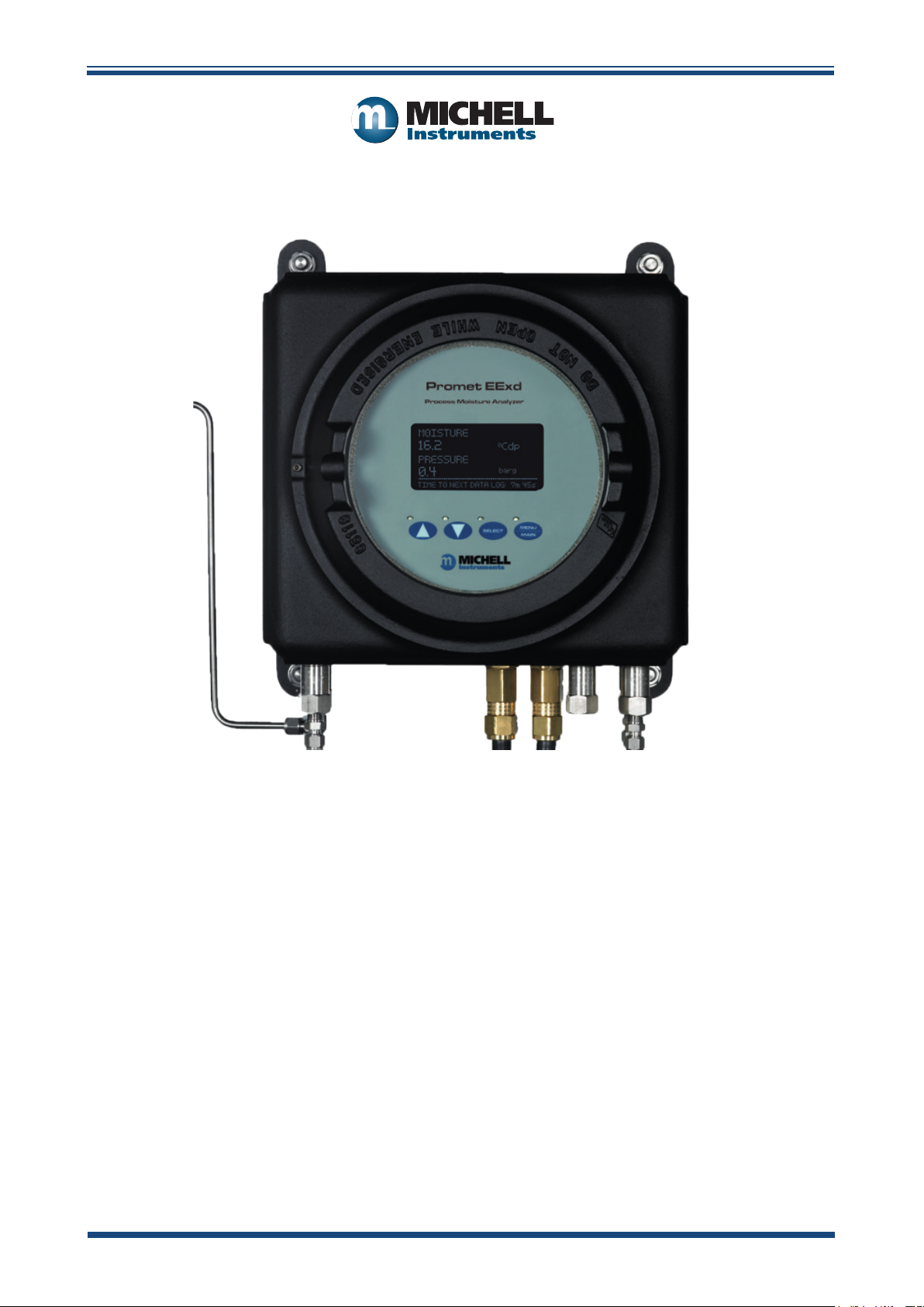
Promet EExd
Process Moisture Analyzer
User’s Manual
97090 Issue 16
April 2019
Page 2

Please ll out the form(s) below for each instrument that has been purchased.
Use this information when contacting Michell Instruments for service purposes.
Analyzer
Code
Serial Number
Invoice Date
Location of Instrument
Tag No
Analyzer
Code
Serial Number
Invoice Date
Location of Instrument
Tag No
Analyzer
Code
Serial Number
Invoice Date
Location of Instrument
Tag No
Page 3
Promet EExd
For Michell Instruments' contact information please go to
www.michell.com
© 2018 Michell Instruments
This document is the property of Michell Instruments Ltd. and may not be copied or
otherwise reproduced, communicated in any way to third parties, nor stored in any Data
Processing System without the express written authorization of Michell Instruments Ltd.
Page 4

Promet EExd User’s Manual
Contents
Safety ...............................................................................................................................vii
Electrical Safety ..........................................................................................................vii
Pressure Safety ...........................................................................................................vii
Toxic Materials ............................................................................................................vii
Repair and Maintenance .............................................................................................. vii
Calibration (factory validation) .....................................................................................vii
Safety Conformity .......................................................................................................vii
Abbreviations .................................................................................................................... viii
Warnings .......................................................................................................................... viii
1 INTRODUCTION ................................................................................................1
1.1 General .............................................................................................................. 1
1.2 Sample Gas Path ................................................................................................ 1
1.3 Operating Overview ............................................................................................ 2
1.4 User Display and Interface .................................................................................. 2
1.5 Advanced Sensor Technology .............................................................................. 2
1.6 Measurement Units ............................................................................................. 3
1.7 Elimination of Temperature Effects ....................................................................... 3
1.8 Calibration Maintenance ...................................................................................... 4
1.9 Promet EExd Sampling System ............................................................................ 4
2 INSTALLATION ..................................................................................................5
2.1 Electrical Safety .................................................................................................. 5
2.1.1 Equipment Ratings and Installation Details ...................................................... 5
2.2 Hazardous Area Safety ........................................................................................ 8
2.3 Pressure Safety .................................................................................................. 9
2.4 Lifting and Handling ........................................................................................... 9
2.5 Analyzer System ............................................................................................... 10
2.5.1 Pipework .................................................................................................... 11
2.5.2 Power Connection ...................................................................................... 13
2.5.3 Analog and Digital Communications ............................................................. 14
2.5.4 Process Alarms and Analyzer Status Alarms .................................................. 14
2.6 Promet EExd Start-Up Purge Procedure .............................................................. 15
2.7 Sample Gas Flows ............................................................................................ 16
2.8 Sample Flow Alarms (Optional) .......................................................................... 16
3 OPERATION ....................................................................................................17
3.1 System Operation ............................................................................................. 17
3.2 User Interface .................................................................................................. 17
3.2.1 Interface Controls ....................................................................................... 17
3.2.2 ‘Up/Down Arrow’ Buttons ............................................................................. 18
3.2.3 ‘SELECT’ Button .......................................................................................... 18
3.2.4 ‘MENU/MAIN’ Button ................................................................................... 18
3.3 Menu Structure ................................................................................................ 19
3.4 MAIN MENU Page ............................................................................................. 20
3.5 STATUS Page ................................................................................................... 20
3.6 LOGGING MENU Page ....................................................................................... 21
3.6.1 VIEW LOGGED DATA Page ........................................................................... 21
3.6.2 VIEW STATISTICS Page ............................................................................... 22
3.6.3 VIEW SYSTEM FAULTS Page ........................................................................ 23
3.7 VIEW/ADJ VARIABLES Page .............................................................................. 23
3.7.1 Password .................................................................................................... 23
3.7.2 VARIABLES Pages ....................................................................................... 24
3.7.3 Single Channel Configuration VARIABLES Pages ............................................ 24
iv 97090 Issue 16, April 2019
Page 5

Promet EExd User’s Manual
3.7.4 Dual Channel Configuration VARIABLES Pages .............................................. 25
3.8 SENSOR INFO Page .......................................................................................... 26
3.9 CONTACT INFO Page ....................................................................................... 27
4 MAINTENANCE ................................................................................................28
4.1 Enclosure Cover and User Interface ................................................................... 28
4.2 Replacement of the Moisture Sensor Assembly ................................................... 29
4.3 Replacement of the Flow Switch (if fitted) .......................................................... 31
4.4 Troubleshooting ................................................................................................ 32
4.4.1 Error Messages ........................................................................................... 32
4.4.2 Logged Error Codes ..................................................................................... 33
4.4.3 Analyzer Status Alarm Relay......................................................................... 34
Figures
Figure 1 Promet EExd Sampling System ....................................................................4
Figure 2 Power Connection Connector .......................................................................5
Figure 3 Earthing Stud And Nut Washer Assembly .....................................................6
Figure 4 Promet EExd Mounting Drawing .................................................................10
Figure 5 Pipework Connections ...............................................................................11
Figure 6 Hook-up Wiring Diagram ...........................................................................13
Figure 7 Minimum Requirements for Start-up Purging ..............................................16
Figure 8 MAIN Page in Single Channel (top) and Dual Channel Modes .......................17
Figure 9 User Interface ..........................................................................................17
Figure 10 Up/Down Arrow Buttons ...........................................................................18
Figure 11 ‘SELECT’ Button ........................................................................................18
Figure 12 ‘MENU/MAIN’ Button .................................................................................18
Figure 13 Menu Structure ........................................................................................19
Figure 14 MAIN MENU Page .....................................................................................20
Figure 15 STATUS Page ...........................................................................................20
Figure 16 LOGGED DATA Page .................................................................................21
Figure 17 STATISTICS Page .....................................................................................22
Figure 18 LOGGED ERROR Page ...............................................................................23
Figure 19 PASSWORD Page ......................................................................................23
Figure 20 VARIABLES Page ......................................................................................24
Figure 21 SENSOR INFO Page ..................................................................................26
Figure 22 CONTACT INFO Page ................................................................................27
Figure 23 Ribbon Cable Connection ..........................................................................29
Figure 24 Moisture Sensor Assembly Replacement .....................................................30
Figure 25 Error Message Line ...................................................................................32
Figure 26 Logged Error Codes ..................................................................................33
Figure 27 Mounting Drawing ....................................................................................38
Figure 28 Pipework Connections ...............................................................................39
Figure 29 System Wiring Diagram .............................................................................40
Figure 30 Calibration Correction Data........................................................................50
Figure 31 Reading Holding Registers State Diagram ...................................................62
Figure 32 Write Single Register State Diagram ...........................................................64
Michell Instruments v
Page 6

Promet EExd User’s Manual
Appendices
Appendix A Technical Specifications ..............................................................................36
A.1 Mounting Drawing ....................................................................... 38
A.2 Pipework Connections ..................................................................39
A.3 System Wiring Diagram ................................................................40
Appendix B Variable Definitions ...................................................................................42
Appendix C Software ................................................................................................... 47
C.1 System Requirements ..................................................................47
Appendix D Modbus RTU Communications .................................................................... 49
D.1 Introduction ................................................................................ 49
D.2 Modbus RTU Basics ...................................................................... 49
D.3 Physical Layer ............................................................................. 49
D.4 Termination Resistor .................................................................... 50
D.5 Register Map ............................................................................... 50
Appendix E Modbus RTU Details ..................................................................................55
E.1 Message Framing .........................................................................55
E.2 Implemented Functions ................................................................56
E.3 Exceptions ..................................................................................60
Appendix F Register Number Formats...........................................................................62
Appendix G Hazardous Area Certification ......................................................................68
G.1 Product Standards .......................................................................68
G.2 Product Certification ....................................................................68
G.3 Global Certificates/Approvals ........................................................ 68
G.4 Special Conditions of Use ............................................................. 69
G.5 Maintenance and Installation ........................................................69
Appendix H Pressure Equipment Directive Compliance Statement ................................... 71
Appendix I Quality, Recycling & Warranty Information ...................................................73
Appendix J Return Document & Decontamination Declaration ........................................75
vi 97090 Issue 16, April 2019
Page 7

Promet EExd User’s Manual
!
Safety
This manual contains all the required information to install, operate and maintain the Promet EExd. Prior
to installation and use of this instrument, this entire manual should be read and understood. Installation
and operation of this product should be carried out by suitably competent personnel only. The operation
of this product must be in accordance with the terms of this manual and associated safety certicates.
Incorrect installation and use of this product for other than its intended purpose will render all warranties
void.
This product is intended for use in a Hazardous Area and is awarded an ATEX, IECEx and CSA Certicate.
The relevant certicates should be fully examined prior to installation or use of this product.
Where this hazard warning symbol appears in the following
sections, it is used to indicate areas where potentially hazardous
operations need to be carried out and where particular attention to
personal and personnel safety must be observed.
Electrical Safety
The instrument is designed to be completely safe when used with options and accessories supplied by
the manufacturer for use with the instrument. The input power supply voltage limits are 90 to 260 V AC,
47/63 Hz.
Pressure Safety
DO NOT permit pressures greater than the safe working pressure to be applied directly to the instrument.
Refer to the Technical Specications in Appendix A.
Toxic Materials
The use of hazardous materials in the construction of this instrument has been minimized. During normal
operation it is not possible for the user to come into contact with any hazardous substance which might be
employed in the construction of the instrument. Care should, however, be exercised during maintenance
and the disposal of certain parts.
Repair and Maintenance
The instrument must only be maintained either by the manufacturer or an accredited service agent. Refer
to www.michell.com for details of Michell Instruments’ worldwide oces contact information.
Calibration (factory validation)
Prior to shipment, the analyzer undergoes stringent factory calibration to internationally traceable
standards, NPL (UK) and NIST (USA). Due to the inherent stability of the instrument, only periodic
calibration is required under normal operating conditions.
Michell Instruments recommends that calibration of the sensor should be maintained on a 12 monthly
basis to ensure optimum operation. Michell Instruments oers a calibration exchange program, where
a refurbished and re-certied sensor is supplied as an operational replacement and the original item
returned to Michell to complete the exchange.
NOTE: This interval may need to be reduced if the operation of the sensor is within potentially
aggressive or corrosive sample media (such as sour natural gas). The calibration interval
may therefore need to be shortened to 6 months (or lower in extreme cases) in order to
maintain satisfactory analyzer performance.
Safety Conformity
This product meets the essential protection requirements of the relevant EU directives. Further details of
applied standards may be found in the product specication.
Michell Instruments vii
Page 8

Abbreviations
The following abbreviations are used in this manual:
A Ampere
AC alternating current
barg pressure in bar (gauge)
°C degrees Celsius
°F degrees Fahrenheit
DC direct current
dp dew point
EU European Union
lb pound
lb/MMscf pounds per million standard cubic feet
lbf-ft pound force per foot
kg kilogram
mA milliampere
max maximum
min minute(s)
mg/m3 milligrams per cubic meter
mm millimeters
mV millivolt(s)
N/C normally closed
N/O normally open
Nl/min normal liters per minute
ppmV parts per million by volume
psig pressure in pound(s) per square inch (gauge)
RH relative humidity
scfh standard cubic feet per hour
temp temperature
V Volts
Promet EExd User’s Manual
Warnings
The following general warnings listed below are applicable to this instrument. They are
repeated in the text in the appropriate locations.
Where this hazard warning symbol appears in the following
sections it is used to indicate areas where potentially
hazardous operations need to be carried out.
Where this symbol appears in the following sections it is used
to indicate areas of potential risk of electric shock.
viii 97090 Issue 16, April 2019
Page 9

Promet EExd User’s Manual
1 INTRODUCTION
1.1 General
The Promet EExd is designed for continuous, automatic measurement of the moisture
content of processed natural gas, utilizing the Michell Ceramic Moisture Sensor. It is the
result of more than 30 years’ experience in the supply of analyzers to the Worldwide Oil
& Gas Industry.
The analyzer comprises either a single or a dual channel moisture measurement sensor
cell, control electronics and a display interface housed in an Exd enclosure. The analyzer
is ATEX Directive, IECEx or cCSAus compliant for use in a Zone 1 or 2 Hazardous Area
and Class I, Div 1 Hazardous Location. See marking label located on right hand side of
analyzer to identify approvals. An accompanying sample handling panel, designed to be
positioned close to the process sample point to prepare the sample prior to entry into
the Promet EExd, can also be supplied.
The instrument offers several user-selectable display options based on a calibrated
dew-point measurement range of -100 to +20°C (-148 to +68°F), traceable to the
humidity metrology standards of NPL (UK) and NIST (USA). The instrument further
provides indication only in the ranges of +20 to +30°Cdp (+68 to +86°Fdp) and -100 to
-120°Cdp (-148 to -184°F), equating to a moisture measurement capability of <1ppbV
to >30,000 ppmV.
INTRODUCTION
The requirements for operation are a 90 to 260 V AC, 47/63 Hz power supply of 180W
and field communications Modbus RTU and/or 4-20 mA. Refer to the System Wiring
Diagram in Appendix A.
1.2 Sample Gas Path
The Promet EExd analyzer system must be supplied with gas at the required pressure,
via a sample gas handling panel providing suitable pressure, filtration & flow control.
Sample gas entry and exit ports direct the gas through flame arrestors which, along with
the Exd enclosure, provide the explosion proof protection. 1 or 2 separate measurement
channels can be accommodated within the instrument.
The measurement system components are housed within a cast aluminum Exd rated
enclosure. The enclosure has a screw cover incorporating a sealed window. It is
chromate primed, polyester coated in black, and provides environmental protection to
IP66/NEMA 4. An enclosure breather is fitted in the form of an additional flame arrestor.
It is important that no pipe connection is made to this breather and that no restriction
is allowed to occur.
All sample gas-wetted metallic parts are manufactured in AISI 316L stainless steel with
Viton soft parts that comply with the NACE standard MR-01-75 (latest edition). Tube
fittings are twin ferrule compression type. All electrical and gas connections are made
through the base of the enclosure. Refer to the Mounting Drawing in Appendix A.
Channel 1 flow components comprise the following:
• (Optional) Flow Switch 1 (FS1): Provides indication that a flow
is present throughout the moisture measurement stream
• Pressure Transducer 1 (PT1): Provides the measurement of
the sample gas pressure within the moisture measurement cell
Michell Instruments 1
Page 10

INTRODUCTION
Channel 2 flow components comprise the following:
• (Optional) Flow Switch 2 (FS2): Provides indication that a flow
is present throughout the moisture measurement stream
• Pressure Transducer 2 (PT2): Provides the measurement of
the sample gas pressure within the moisture measurement cell
1.3 Operating Overview
The system continuously measures dew point/moisture and pressure in an uninterrupted
gas stream flow. The flow switch, if fitted, will notify the system if the gas flow falls
below the recommended rate.
Moisture and pressure for each channel are logged at a user-defined interval. The logs
are available through the user interface or via the serial communications. Two 4–20 mA
outputs for each channel are available to remotely read the dew point/moisture and
pressure in real time.
Promet EExd User’s Manual
1.4 User Display and Interface
The Promet EExd User Display and Interface Unit is presented via the circular window
of the enclosure. Operation is achieved by a unique system, which allows full control
through the glass of the enclosure cover. The cover is fully detachable for greater
access into the enclosure during the installation and initial set-up of the instrument.
During normal operation of the instrument the cover must remain fully secured.
1.5 Advanced Sensor Technology
The Promet EExd utilizes the Michell Ceramic Moisture Sensor, an advanced impedance
sensor technology with more than 1,000 installations in natural gas and petrochemical
applications today. Semiconductor thick- and thin-film technologies combine in metallized
ceramics and achieve a durable sensor with measurement capability from lower than 10
ppbV moisture content and high-pressure capability up to 138 barg (2000 psig).
Unlike older aluminum-oxide technologies, the inherent immunity to pressure shock of
the Ceramic Sensor avoids the risk of sensor failure at commissioning or shut-down.
The inert nature of the sensor gives long-term resistance to chemical attack, even in
extremely sour gas with percentage level H2S concentrations. The Ceramic Sensor
response characteristic is proportional to the partial pressure of water vapor in the gas
being measured, which is directly related to the dew-point temperature.
2 97090 Issue 16, April 2019
Page 11

Promet EExd User’s Manual
1.6 Measurement Units
The Promet EExd offers complete flexibility for the user to select their preference of
hygrometric units. Integral pressure measurement enables unit conversions from dew
point to moisture content, or dew point to dew point for different pressure conditions.
The available units of dew point/moisture content are as follows:
Dew-Point Temperature
• °C or °F dew point
• °C or °F dew point calculated for a set pressure level input by
the user, for either ideal or natural gas
Moisture Content (parts per million)
• ppmV for ideal gas (Ppm(v) IG)
• ppmV for natural gas (Ppm(v) NG)
INTRODUCTION
Moisture Content (pounds per million standard cubic feet)
• lb/MMscf for natural gas (LBMMSCF)
Milligrams per normal cubic meter
• mg/m3 natural gas (mgm-3)
The firmware of the Promet EExd incorporates conversion data for ideal gases and
natural gas. For natural gas the conversions are performed based on the long established
IGT Research Bulletin No. 8 or the recently published ISO 18453, to customer order
preference.
1.7 Elimination of Temperature Effects
To ensure continuous optimum analysis conditions the Promet EExd Main Unit is
temperature controlled (internally) at a stable level. The control temperature level is
selected to suit the climate at the point of installation, being set to the normal maximum
temperature. Such steady state control within the analyzer greatly reduces the effects
of diurnal (day-night) swings in temperature. These temperature changes could induce
transitional adsorption and desorption effects of the flowing sample, resulting in
erroneous measurements.
In addition, the Promet EExd utilizes an advanced temperature compensation algorithm
that automatically maintains best possible measurement accuracy in the event of heater
failure or if the prevailing climate exceeds the set temperature level.
Michell Instruments 3
Page 12
INTRODUCTION
1.8 Calibration Maintenance
Maintenance of calibration is essential to the lifetime performance of all analyzers. To
ensure that all customers worldwide can maintain the performance of their Promet EExd,
the unique Michell Calibration Exchange Service offers freshly calibrated replacement
Ceramic Sensors certified traceable to NPL and NIST. As the calibration characterization
data for each Promet EExd Sensor is programmed into on-board non-volatile memory,
fitment of the Calibration Exchange Sensor refreshes the calibration, returning the
measurement performance to day-one with down-time of only a few minutes while
the interchange is made. No programming or data input is required by the user to
complete this. The calibration exchange is available globally on swift delivery, typically
less than two weeks, and at the same or less then the cost of a traditional ‘return to
manufacturer’ re-calibration service.
The recommended calibration maintenance interval is 12 months for sweet gases and
6 months for sour gases.
Michell recognises that some customers wish to carry out their own calibration
adjustments in the field using either a portable dew-point generator (ATSM D5454),
or against a calibrated reference hygrometer or certified moisture-in-gas cylinders.
The Promet EExd accommodates all such needs within the operating firmware that
offers user-friendly access to the calibration characterization table for re-calibration
adjustments to be made at just one point (for example, using a certified cylinder gas)
or multiple points (using a field generator) across the measurement range.
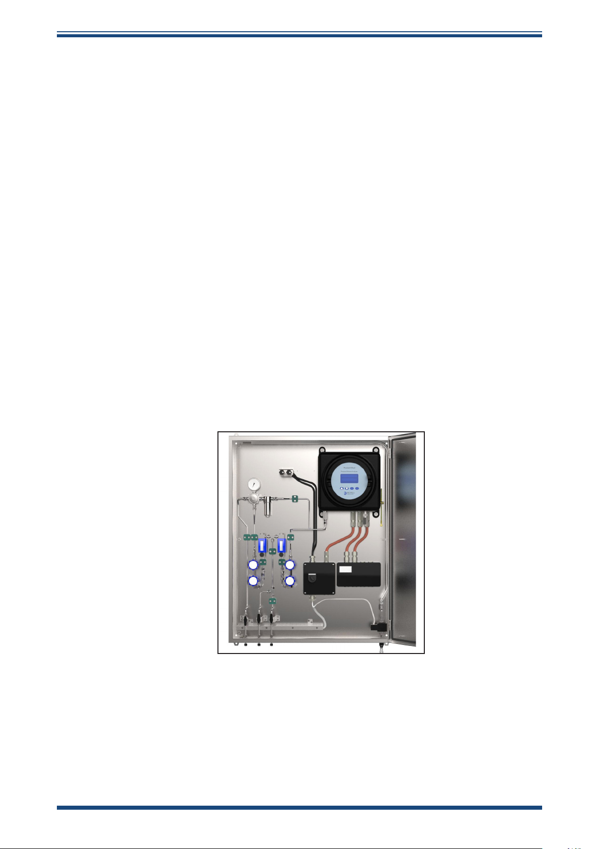
1.9 Promet EExd Sampling System
Promet EExd User’s Manual
(Optional – see separate manual if you have purchased this item)
Figure 1
Promet EExd Sampling System
Good sample conditioning and handling is particularly important in the field of moisture
measurement. As the moisture sensor has to be exposed directly to the process liquid
stream in order to detect the dissolved moisture present, key sampling issues such
as the avoidance of particulate contamination are imperative to successful operation.
Michell’s 30 years of expertise in on-line process moisture analyzers are used to optimize
the design of the Promet EExd Sampling Systems.
Contact Michell Instruments for further details: www.michell.com.
4 97090 Issue 16, April 2019
Page 13
Promet EExd User’s Manual
!
2 INSTALLATION
2.1 Electrical Safety
During the installation of this product ensure that all
applicable national and local electrical safety regulations
Always ensure that power is switched off prior to accessing
the product for any purpose other than normal operation or
INSTALLATION
WARNING:
are observed.
WARNING:
Isolate the power prior to installation.
WARNING:
prior to disconnecting any cables.
2.1.1 Equipment Ratings and Installation Details
The following mandatory statements refer to the Ex certified Promet EExd Analyzer only
(not including the sampling system).
This equipment must be supplied with a voltage between the range of 90 to 260 V AC,
47/63 Hz. Maximum power rating is 180 W.
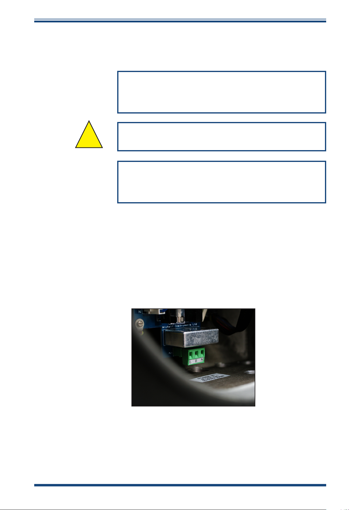
The power is connected via PL1 on the mains connector PCB.
Figure 2
All input and output connectors are 2-part PCB mounted type, rated at 300 V 10 A.
The detachable, screw terminal half of each connector is designed to accept 0.5 to
2.5mm2 [24 -12 AWG] stranded or solid conductors.
Power Connection Connector
Michell Instruments 5
Page 14
INSTALLATION
Any power connection cable should be 3 core over sleeved, with minimum 0.5mm
insulation and rated at 300 V. Cables should have Live (L), Neutral (N) and Earth
[Ground] (E) conductors. Ensure suitably rated power supply cables and glands are
used to ensure that electrical safety is maintained. Connect each of the Live (L), Neutral
(N) and Earth [Ground] (E) conductors to the similarly marked terminals (L, N, E) on
the Power In connector shown in Figure 3 above. Ensure the power supply can deliver
sufficient power consumption requirement.
Any power supply terminals and voltages must be suitably separated from the other I/O
requirements of this product.
Before applying power, perform a continuity test to ensure that the power supply cable
and product are effectively connected to the protective Earth.
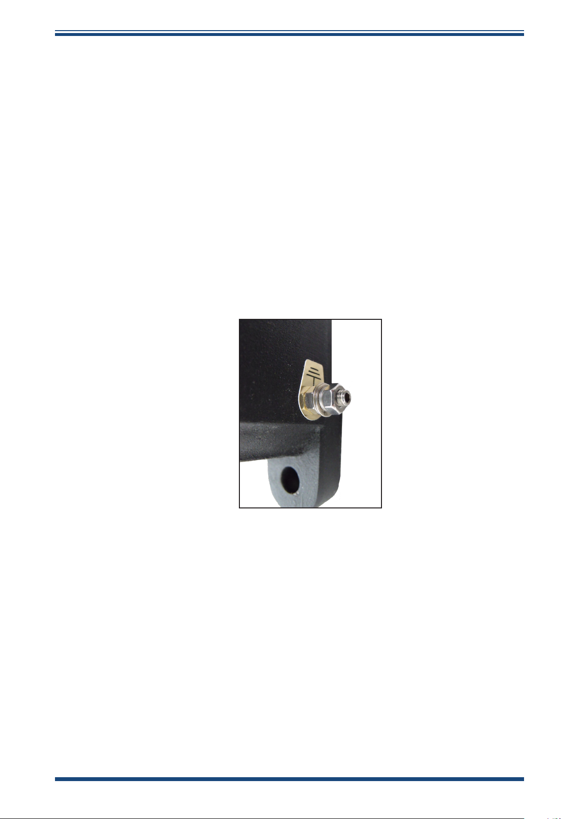
The Protective Earth terminal is mounted internally and the Earth wire connected to it
should never be disconnected. The product enclosure is supplied with an external earth
stud at the lower right hand side. At installation, connect this earth stud to plant earth
by a minimum 4mm2 earthing bonding. M6 stud and 2 off M6 nuts and washers, all
nickel plated.
Promet EExd User’s Manual
Figure 3
Fuse: A replacement fuse can be obtained by contacting Michell Instruments' technical
support. Fuse rating = 5 x 20mm 2.5 A anti-surge to IEC 60127-2.
This product is designed to be safe at least under the following conditions: between a
temperature range of -40 to +60°C (-40 to +148°F), in maximum 80% relative humidity
for temperatures up to +31°C (+88°F) decreasing linearly to 50% RH at +50°C
(+122°F). Supply voltages of ±10% and transient over voltages up to Overvoltage
Category II. Pollution Degree 2. Altitudes up to 2000m. Outdoor mounting is permitted
using suitably rated glands equivalent to NEMA 4 / IP66. See Appendix A, Technical
Specification, for full operating parameters.
Do not remove or exchange any of the cables or electrical components supplied with
this product. Doing so will invalidate all warranties.
There are no additional or special electrical safety requirements other than those
referred to in this manual.
Earthing Stud And Nut Washer Assembly
6 97090 Issue 16, April 2019
Page 15

Promet EExd User’s Manual
Location and mounting arrangements - refer to the relevant sections of this manual for
the location and mounting details.
Installation of this equipment must include the provision of a suitable and locally
positioned power isolation switch or circuit breaker. Indication of the purpose of the
switch or circuit breaker is strongly recommended. An over-current protection device
should be rated to a maximum of 10 A.
This equipment and all power isolation devices must be installed in a location and
position that allows safe and easy access to their operation and is able to rigidly support
the equipment.
Do not install this equipment in a location that would expose it to impact or high levels
of vibration.
Operation of this equipment, other than in a manner specified by the manufacturer, may
impair the safety protections provided.
The safe installation of this equipment and any system incorporating this equipment is
the responsibility of the installer. Ensure local regulations and requirements are referred
to prior to any installation commencing.
INSTALLATION
Michell Instruments 7
Page 16
INSTALLATION
!
2.2 Hazardous Area Safety
Refer to Appendix G for the Hazardous Area Certification of this product.
This product is fitted with a marking label that contains Hazardous Area information
pertinent to the suitable location and installation.
During all installation and operation activities, local regulations and permitted working
routines must be observed. Installation should only be performed by competent personnel
and in accordance with the latest version of IEC/EN60079-14 or local equivalent.
Repair and servicing of this equipment must only be carried out by the manufacturer.
An Installation and Maintenance Information Sheet is supplied separately to the manual.
This product is certified safe for use in a Zone 1 and Zone 2
area only. This product must not be installed or used within
Promet EExd User’s Manual
WARNING:
a Zone 0 area.
WARNING:
This product must not be operated within an explosive
atmosphere greater than 1.1 bara.
WARNING:
This product must not be operated with enriched oxygen
gas samples (more than 21% oxygen content).
WARNING:
This product must not be operated outside of the
temperature range of -40 to +60°C
WARNING:
The enclosure of this product provides Exd protection, partly
through the threads used for mounting the lid, stopping
plugs and cable gland. At all times effort should be made to
ensure these threads are suitably protected from damage
and that only appropriately rated mating parts are applied
to them, in accordance with the certifying requirements.
8 97090 Issue 16, April 2019
Page 17
Promet EExd User’s Manual
!
!
!
2.3 Pressure Safety
This product is used in conjunction with pressurized gases.
Observe pressurized gas handling precautions.
Pressurized gas should only handled by suitably trained personnel.
INSTALLATION
WARNING:
WARNING:
Pressurized gas is dangerous.
This product requires pressurized gas to be connected to it. Observe pressurized gas
handling regulations. Only suitably trained personnel should carry out tasks that include
the use of pressurized gas mediums.
2.4 Lifting and Handling
Personnel must observe suitable lifting and handling precautions.
This product is not designed as portable or transportable equipment. It should be rigidly
fixed in position as per the full installation instructions.
The weight of the analyzer is in excess of 18kg. Therefore, appropriate lifting and
handling techniques should be used during the installation process. Before commencing
any lifting or handling ensure that its intended location is suitable and appropriately
prepared. Make sure that mounting point design considerations have employed locally
approved safety factors.
WARNING:
This instrument is in excess of 18kg.
When handling and installing this product (particularly after removal from its packaging)
ensure that it is not dropped, impacted or subjected to high levels of vibration or
environmental conditions that may impair its operation.
Michell Instruments 9
Page 18

INSTALLATION
2.5 Analyzer System
Refer to the Installation & Maintenance Information sheet (supplied separately) and the
System Drawings in Appendix A.
The instrument is housed in an aluminum EExd enclosure suitable for wall or panel
mounting. Four mounting points are available with M12 clearance holes on fixing
centres of X = 270mm x Y = 318mm.
Height: 355mm (13.9”)
500mm (19.68”) including installation clearance
Width: 310mm (12.20”)
500mm (19.68”) including installation clearance
Depth: 245mm (9.64”)
The enclosure provides environmental ingress protection IP66 and should be mounted
vertically in a location free of any appreciable vibration. It should be placed in a shaded
position to prevent heating effects through sun radiation.
Promet EExd User’s Manual
The weight of the analyzer is 21kg (46lbs).
245mm 9.65"
355mm [13.9"]
Sample out - Channel 1
1/8" NPT Female (ATEX/IECEx/CSA)
Sample in - Channel 1
1/8" NPT Female (ATEX/IECEx/CSA)
290mm [11.41"]
Flame Arrestor
Flame Arrestor
270mm 10.63"
4 o M12 (1/2")
Clearance
318mm 12.52"
Enclosure Breather
Flame Arrestor
Do NOT obscure
Sample Out - Channel 2 (Optional)
Flame Arrestor
1/8" NPT Female (ATEX/IECEx/CSA)
Sample In - Channel 2 (Optional)
Flame Arrestor
1/8" NPT Female (ATEX/IECEx/CSA)
Cable Entry Glands
3 o M20 (ATEX)
3 o 1/2" NPT (CSA)
Figure 4
310mm [12.20"]
Promet EExd Mounting Drawing
10 97090 Issue 16, April 2019
Page 19
Promet EExd User’s Manual
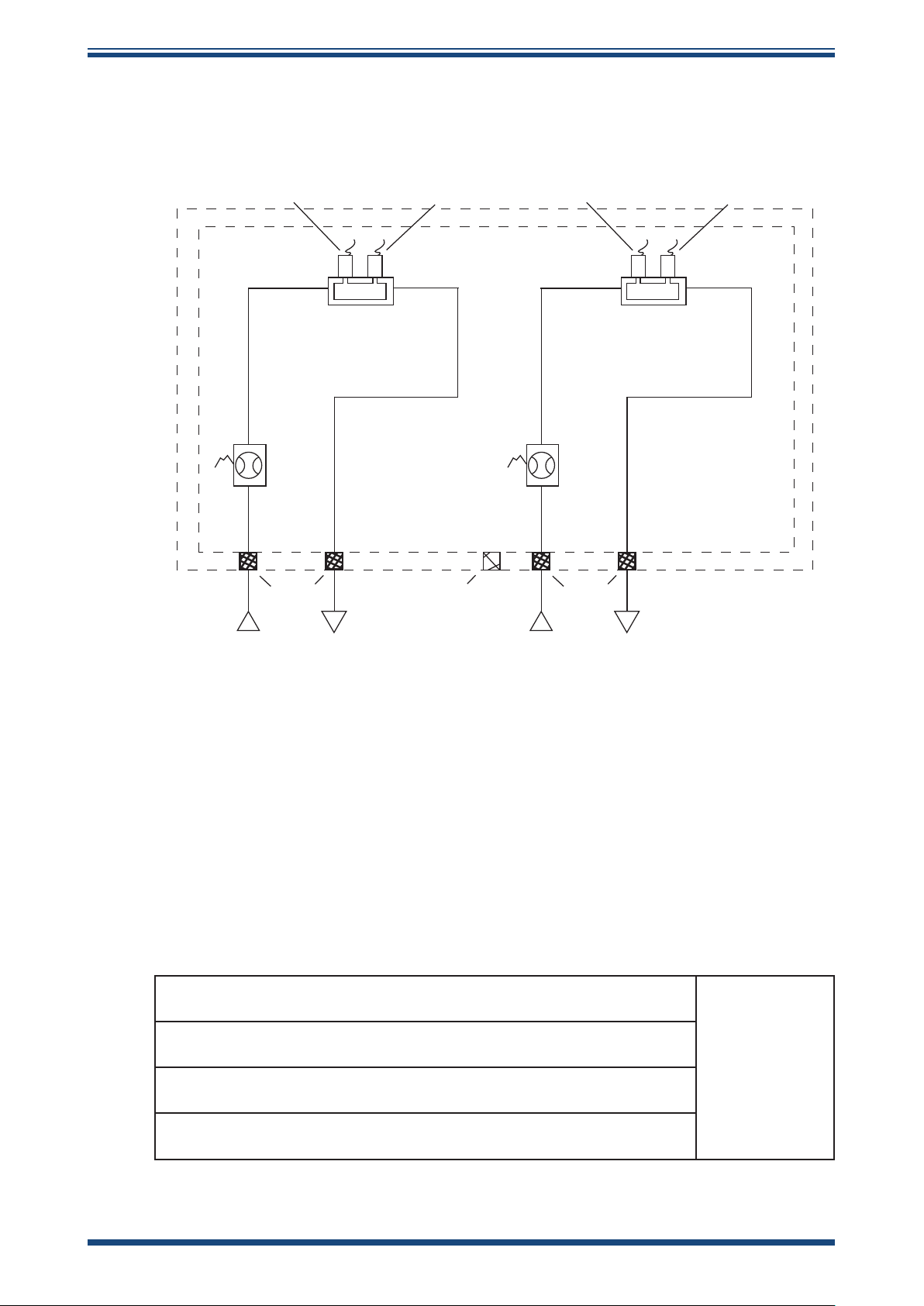
2.5.1 Pipework
CHANNEL 1 CHANNEL 2
MICHELL MOISTURE
SENSOR
PRESSURE
TRANSMITTER
MICHELL MOISTURE
SENSOR
INSTALLATION
PRESSURE
TRANSMITTER
GAS SAMPLING BLOCK
FLOW
SWITCH
(optional)
ARRESTORS
GAS IN GAS OUT
FLAME
FLAME
ARRESTOR
BREATHER
GAS SAMPLING BLOCK
FLOW
SWITCH
(optional)
ARRESTORS
GAS IN GAS OUT
FLAME
Figure 5
Pipework Connections
Note: Ensure that the process sample gas supply line is well flushed through
to clear any liquids and debris present prior to connection to the instrument. A
sample handling system must prepare the gas in terms of pressure regulation
and filtration before entering into the measurement system.
In accordance with the Certification requirements, the Promet EExd must have, as a
minimum, the components described in Figure 7.
The pipework connections are as follows:
Water dew-point Channel 1 Gas Sample inlet
(Maximum pressure of 138 barg (2000 psig))
Water dew-point Channel 1 Gas Sample outlet
(Vent to atmosphere or low pressure are line)
1/8” NPT(F)
Water dew-point Channel 2 Gas Sample inlet
(Maximum pressure of 138 barg (2000 psig))
Water dew-point Channel 2 Gas Sample outlet
(Vent to atmosphere or low pressure are line)
Michell Instruments 11
Page 20

INSTALLATION
The following points should be considered when installing the sample gas supply line:
PTFE tape is recommended for pipe connections. Solvent based pipe thread sealant
should not be used, as condensable components or contaminates can be leached during
the curing period.
It is recommended that Viton is used for all O-rings.
Care and attention to the position and installation of the piping will minimize problems
caused by avoidable contamination of the measurement system. The most common
cause of difficulty is the accumulation of liquid in impulse lines during a shutdown
period. If the measurement system has not been isolated on restart-up, condensate
can be displaced into components and associated pipe work within the measurement
system.
If this event follows a period when process lines may have been contaminated by nonhydrocarbons, e.g. glycol, corrosion inhibitors, etc., the problem is magnified. Similarly,
difficulty will be encountered in sample gases carrying liquids, including hydrocarbon
liquids.
Promet EExd User’s Manual
Our recommendations are:
• The sampling point on the process line should be on the top of the pipe. If
a radial probe is used, the orifice should face downstream. Sample should
be taken from middle 1/3 pipe internal diameter.
• The internal volume of the impulse tubing between the process line and
any sampling system should be as low as possible (sample lines should
be kept as short as possible) to minimize response lag time to changing
process conditions.
• Piping should be lagged and/or trace heated if ambient temperatures
could cause the sample gas to fall below its dew-point temperature.
• A drain valve should be placed at the low point (if any) in the system.
• It should be standard procedure to isolate the measurement system
during shutdowns or when plant problems are being experienced. The
supply lines must be fully purged before restarting.
• The relatively large area of surfaces and internal volume of pressure
regulators can be particularly troublesome if contamination is experienced.
Prolonged purging with gas may be necessary to remove the contamination.
Stripping and cleaning, followed by purging of the system, is preferred.
• Avoid sample gas streams that are already very close to the dew point
or which have dispersed liquid (not necessarily hydrocarbon) burden. In
such cases, sampling from fast loops and/or from downstream of existing
catch pot/coalesce systems is always preferred.
NOTE: Failure to observe these recommendations will potentially cause
problems of contamination as well as causing consequential inaccurate,
unreliable and inconsistent monitoring. If a top-entry sample point
is not available, extra attention should be given to the design of the
sample line installation to avoid unwanted contamination.
12 97090 Issue 16, April 2019
Page 21
Promet EExd User’s Manual
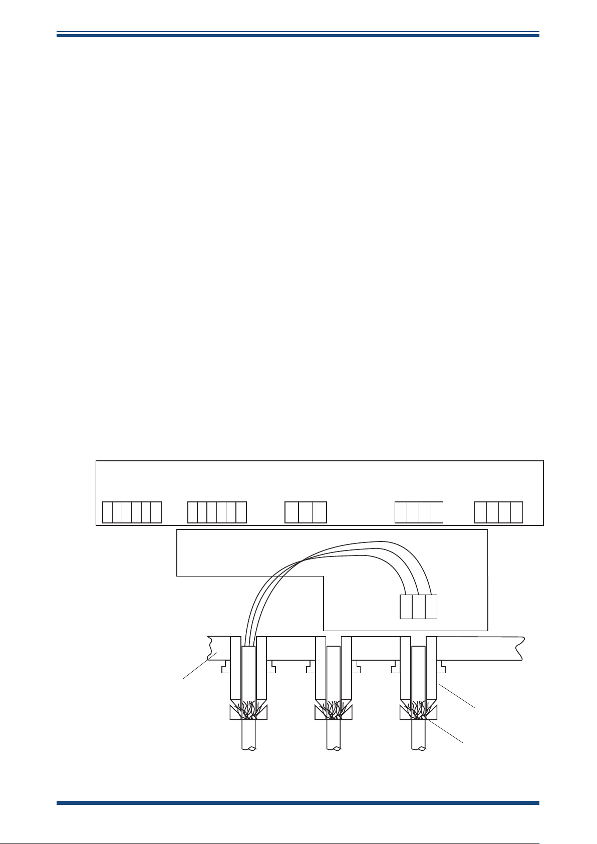
2.5.2 Power Connection
A single-phase AC power connection is required.
The power supply can accommodate voltages from 90 to 260 V AC, 47/63 Hz. The unit
requires a maximum of 180 W to function correctly.
The connection is made via a two-part connector mounted at the base of the unit. See
Appendix A.
Cable entry into the measurement system is made through the bottom of the enclosure.
• For ATEX/IECEx compliant versions of the product 3 off ISO M20 tapped
holes are provided
• For cCSAus compliant version of the product 3 off ½” NPT entries are
provided
INSTALLATION
NOTE: For ATEX/IECEx installations EExd Stopping Glands MUST be used
when installing. Refer to the separate Installation & Maintenance Information
sheet supplied.
The terminals are marked:
L = Live
N = Neutral
E = Earth
AL3AL2AL1 AL4 COMMS Channel 1 Channel 2
mA1+
mA1-
mA2+
NC C NO NC C NO
1 2 3 4 5 6
NC C NO NC C NO
PL16
7 8 9 10 11
B A GND
12
PL20 PL15 PL14 PL19
13 14 15
16 17 18 19 20 21 22 23
mA2-
mA3+
mA3-
mA4+
mA4-
L E N
Enclosure wall
Gland
Cable screen
Figure 6
Hook-up Wiring Diagram
Michell Instruments 13
Page 22

INSTALLATION
2.5.3 Analog and Digital Communications
Two active 4-20 mA outputs and a Modbus RS485 digital interface (see Appendix F for
details) are provided with the Promet EExd. mA1 and mA3 output the moisture values.
mA2 and mA4 output the pressure values of Channels 1 & 2 respectively.
NOTE: The maximum output resistance for the 4-20 mA outputs is 500Ω.
See Section 3.7 for setting the 4-20 mA outputs via the user interface and Appendix F
for setting the outputs via the Modbus interface.
Refer to Figure 6 for cable wiring.
2.5.4 Process Alarms and Analyzer Status Alarms
Promet EExd User’s Manual
Each channel has an associated process and fault alarm, as shown below:
AL1: Channel 1 process alarm
AL2: Channel 1 fault alarm
AL3: Channel 2 process alarm
AL4: Channel 2 fault alarm
Each alarm relay features Normally Open (N/O), Normally Closed (N/C) and Common
(C) contacts.
The process alarm contacts change state when the moisture value is greater than the
alarm set point.
The fault alarm contacts change state when an error associated with the channel occurs,
or when there is a supply failure.
14 97090 Issue 16, April 2019
Page 23

Promet EExd User’s Manual
2.6 Promet EExd Start-Up Purge Procedure
This is a mandatory procedure stipulated in the ATEX/
IECEx certification of the product. The procedure must be
fully carried out prior to the Promet EExd having any power
or signal connections applied. It must also be fully carried
out after the Promet EExd and associated gas handling
equipment has been installed and leak checked. Always
refer to Appendix G.4 - Special Conditions of Safe Use.
This procedure must be carried out at any time following
service or maintenance periods that cause any of the Promet
EExd or associated gas handling equipment pipe work to be
disconnected.
INSTALLATION
It is not necessary to carry out this procedure if power or
signal connections only have been disconnected.
1. Before start-up, ensure that all power and signal connections to the
Promet EExd are fully isolated
2. Ensure that all Inlet & Outlet gas connections to the Promet EExd are
made correctly and are leak tight checked.
3. Fully open the flow control valve of the flow meter of each channel.
4. Fully open the sample gas inlet isolation valves.
5. Adjust open the pressure regulators until full scale flow is observed on
each of the water dew-point channels.
6. Allow the sample gas to purge the system for the period of time indicated
in the table below:
TOTAL PURGE TIME
must be a minimum of 1 minute at 1 Nl/min (2.1 scfh)
Assumes total system pipe length is 3m (9.8’) and internal pipe bore is
the recommended 4mm (0.16”) internal bore.
For every additional 1m (3.3’) of pipe work, continue the Gas Purge for
an additional 15 seconds at 1 Nl/min (2.1 scfh).
7. After the appropriate purge duration, close the gas inlet isolation valve.
8. Ensure the window is replaced and fully secured before applying the
power.
Michell Instruments 15
Page 24

INSTALLATION
Promet EExd User’s Manual
MINIMUM REQUIREMENTS FOR START UP PURGING
PRESSURE
GAS INLET
GAS INLET
GAS INLET
ISOLATION VALVE
GAS INLET
ISOLATION VALVE
NOTE:
CONNECTING PIPEWORK TO BE 4mm I/D BORE, 316L STAINLESS STEEL TUBE
PRESSURE
Figure 7
2.7 Sample Gas Flows
The flow through each channel should be set at approximately 2 Nl/min (4.2 scfh). This
flow setting figure is not required to be precise. Its purpose is only to ensure that a
representative sample of gas is presented to the measurement sensor.
GAUGE
GAUGE
PRESSURE
REGULATOR
PRESSURE
REGULATOR
WATER DEW-POINT
CHANNEL-1
GAS IN GAS OUT
PROMET EExd
GAS IN GAS OUT
WATER DEW-POINT
CHANNEL-2
FLOWMETER
FLOWMETER
Minimum Requirements for Start-up Purging
NON-RETURN
VALVE
GAS OUTLET
To increase the speed of response of the measurement of the main process gas it is
highly recommended that a fast bypass loop be installed into the gas sampling system.
The recommended flow through the bypass loop should be approximately 3 times that
of the measurement channel. Therefore, typically, the bypass gas flow should be set to
approximately 6 Nl/min (12.7 scfh).
2.8 Sample Flow Alarms (Optional)
The optional flow switches are supplied to alert the user to either severely reduced
or discontinuation of the sample gas flow through the system. An alarm state will be
indicated on the error message line at the bottom of the MAIN Page. See Section 4.4 on
troubleshooting for further details.
When the flow of sample gas is set correctly, the alarm states will be indicated when
the gas flows have lowered into a range deemed unsuitable for effective measurements
to be made.
The flow switches are adjusted during factory test to activate the alarm when the
flow falls below approximately 10 to 20% of the normal recommended sample flow
setting (see Section 2.7). During the factory setting procedure the gas pressure that
is applied represents the most common application analysis conditions for water dewpoint sensors {68 barg (986 psig)}. The operation of these variable area flow switches
are influenced by pressure. For increased pressure the flow alarm activation point will
be at a higher flow rate and conversely, for reduced pressure, the activation point will
be at a lower rate. These devices exhibit a hysteresis that may require a flow of greater
than 100% of the recommended flow setting for a brief period in order to clear the
alarm condition.
NOTE: If the Promet EExd is going to be operating with significantly different
analysis pressures to those used during factory testing then fine re-adjustment
of the flow switches may be beneficial to suit the application conditions. If
this is the case, contact Michell Instruments (www.michell.com) for guidance
on how adjustments can be made on site.
16 97090 Issue 16, April 2019
Page 25

Promet EExd User’s Manual
3 OPERATION
3.1 System Operation
At switch-on, the instrument will display the MAIN Page. It will synchronise itself to
the on-board real time clock, in order to begin logging data at the next minute that is
a multiple of 5 i.e. 5, 10, 15 etc. The MAIN Page will show the moisture and pressure
readings of either 1 or 2 sensors and a countdown to the time when it will take the
next data log. Figure 9 shows the MAIN Page for both 1 and 2 sensor configurations.
Pressing the MENU/MAIN button from this page will take you to the MAIN MENU Page
(see Section 3.4).
MOISTURE
OPERATION
Figure 8
3.2 User Interface
3.2.1 Interface Controls
16.2
0
Cdp
PRESSURE
0.4
TIME TO NEXT DATA LOG: 7m 45s
barg
CH 1
0.0 0Cdp
0 psig
CH 2
-80.0
0
Cdp
0 psig
TIME TO NEXT DATA LOG: 7m 45s
MAIN Page in Single Channel (top) and Dual Channel Modes
Promet EExd
Process Moisture Analyzer
MOISTURE
16.2
PRESSURE
0.4
TIME TO NEXT DATA LOG: 7m 45s
Up/Down
Buttons
Figure 9
Arrow
0
Cdp
barg
MENU
SELECT
MAIN
SELECT
MENU/
Button
MAIN
Button
User Interface
VFD Display
Blue LEDs
Figure 10 illustrates the user interface. It has a vacuum fluorescent display and four
touch sensitive pads that facilitate user interaction through the glass of the enclosure.
Michell Instruments 17
Page 26

OPERATION
3.2.2 ‘Up/Down Arrow’ Buttons
Promet EExd User’s Manual
The Up () and Down () buttons are used to change pages, scroll through lists and
adjust values.
3.2.3 ‘SELECT’ Button
The SELECT button is used to select or de-select a highlighted item in a menu list.
Figure 10
Figure 11
Up/Down Arrow Buttons
SELECT
‘SELECT’ Button
3.2.4 ‘MENU/MAIN’ Button
The MENU/MAIN button is used to toggle between the MAIN Page and the MAIN MENU
Page, or return to the MAIN Page from any location within the menu structure.
Figure 12
MENU
MAIN
‘MENU/MAIN’ Button
18 97090 Issue 16, April 2019
Page 27

Promet EExd User’s Manual
3.3 Menu Structure
Figure 14 shows a map of the menu structure.
KEY
Choices
Menu Pages
Other Pages
NO
Main Menu
Status Page
SELECT
Error ?
YES
Error Report
Page
SELECT
SELECT
STATUS
View
Logged
Data
SELECT
LOGGING
MENU
View
Statistics
SELECT
Page
1
Page
2
SELECT
View
System
Faults
SELECT
Logged
Error Codes
Start-Up
Banner
Main Page
MENU
MAIN
VIEW/ADJ
VARIABLES
SELECT
Password
Page
NO
SELECT
Password
Correct?
YES
SENSOR
INFO
SELECT
WDP Sensor
OPERATION
MENU
MAIN
Press MENU/MAIN button to
get back to Main Page from
any location
MENU
MAIN
CONTACT
INFO
SELECT
Info
Contact/About
Logged Pages
Figure 13
Page
1
Page
2
Page
3
Variables Pages
Menu Structure
Use Up/Down arrow buttons
to scroll through
menu items and pages
Michell Instruments 19
Page 28

OPERATION
3.4 MAIN MENU Page
This page is accessed by pressing the MAIN/MENU button from the MAIN Page. The
instrument’s status, variables, logged data and system information are available through
this page. Use the Up () and Down () buttons to highlight the page of interest and
press the SELECT button to access.
Promet EExd User’s Manual
MENU
STATUS
LOGGING MENU
VIEW/ADJ VARIABLES
SENSOR INFO
CONTACT INFO
3.5 STATUS Page
This page shows the status of the process alarm and flow for one or both channels,
depending upon the configuration. When the measured moisture value rises above the
alarm set-point, the moisture alarm condition will be displayed as ON*ALERT*. No flow
is displayed as OFF*ALERT*.
Figure 14
MAIN MENU Page
STATUS PAGE
ALARM CONDITIONS
CHANNEL 1 MOI :ON
CHANNEL 1 FLOW :ON
TIME TO NEXT DATA LOG: 2m 11s
Figure 15
STATUS Page
XALERTX
Press the MAIN/MENU button to return to the MAIN Page.
20 97090 Issue 16, April 2019
Page 29

Promet EExd User’s Manual
3.6 LOGGING MENU Page
This page allows the viewing of data or statistical information on the logged data. Press
the SELECT button to see the following options:
View Logged Data
View Statistics
View System Faults
Press the Up () and Down () buttons and the SELECT button to enter these options
pages.
If there is no data available then No Data Available will be displayed and no access will
be given to the other two options.
3.6.1 VIEW LOGGED DATA Page
OPERATION
This page allows access to the previous measurement results made by the instrument.
A rolling total of a maximum of 150 samples can be logged, which represents a
measurement history of 150 x (measurement time) in minutes. Sample 1 represents
the most recent measurement taken. After 150 measurements have been logged, the
oldest measurement will be deleted and replaced as each new measurement is logged.
Caution: Changing the moisture value, e.g. from dew point to ppm, will result
in the loss of all logged data.
Access to each measurement sample is via the Up () and Down () buttons, which
may be used to scroll through each page of information. If faster scrolling is required
(to quickly move to another sample) press the SELECT button and the sample number
will increase by 10. When the sample number selected is greater than that acquired, or
is greater than 150, Sample 1 will be selected and displayed.
Sample Number Time of Sample
Date (day/month)
LOGGED DATA
NO. 1 10:20 29/06
MOI 6.2 oCdp
PRES 0.2 barg
Figure 16
Michell Instruments 21
LOGGED DATA Page
Page 30

OPERATION
Each page of logged data contains:
• Sample number 1 to 150, 1 being the most recent
• Date of sample dd/mm
• Time of sample 24 hr format, hh:mm
• The values of Moisture content/Dew point and Pressure
• The units of measurement
Press the MAIN/MENU button to return to the MAIN Page.
3.6.2 VIEW STATISTICS Page
These pages display the maximum, minimum and average values for each measured
parameter for up to 150 previous measurement samples. RESET LOG on the MAIN
MENU Page re-sets the logging statistics.
Promet EExd User’s Manual
for 1 or 2 channels
STATISTICS PAGE 1/2
MOI MAX 0.6
o
C
at 08:00 on 02/03
o
MOI MIN 0.6
C
at 08:00 on 02/03
MOI AVR 0.6
Figure 17
Use the Up () and Down () buttons to scroll through the statistics.
Press the MAIN/MENU button to return to the MAIN Page.
STATISTICS Page
o
C
22 97090 Issue 16, April 2019
Page 31

Promet EExd User’s Manual
3.6.3 VIEW SYSTEM FAULTS Page
This page displays a record of the last six system faults that have occurred and have
subsequently been corrected. This assists in the diagnosis of any past anomaly in
measured values. Any present system faults will be displayed in the bottom message
line of the MAIN Page.
LOGGED ERROR CODES
CODE TIME & DATE
0008 11:10 02/08/12
OPERATION
Figure 18
Refer to Section 4.4 for descriptions of the error messages and codes.
Press the MAIN/MENU button to return to the MAIN Page.
3.7 VIEW/ADJ VARIABLES Page
For more information on each variable refer to Appendix B.
3.7.1 Password
To safeguard against unauthorized adjustment of set-up parameters and variables, an
entry lock is provided.
The user must first input the access code to enter the VIEW/ADJ VARIABLES Pages.
The password is: 7316
LOGGED ERROR Page
ENTER PASSWORD
USE ARROW KEYS AND
SELECT KEY
0 0 0 0
Figure 19
Use the Up () and Down () buttons to change the highlighted digit and press the
SELECT button to enter and move to the next digit. Inputting 4 correct digits will result
in access to the VARIABLES Pages as detailed in the following sections.
Michell Instruments 23
PASSWORD Page
Page 32

OPERATION
20
3.7.2 VARIABLES Pages
Three pages (four pages in the dual channel configuration) are used to display the
system variables. They can be adjusted by using the Up (), Down () and SELECT
buttons.
Use the Up () and Down () buttons to scroll through the list and from page to page.
To select a variable for adjustment, scroll to the desired variable and press the SELECT
button. A small box will appear beside the value to indicate that it can be adjusted. Use
the Up () and Down () buttons to change the value. NOTE: Numerical values
can be changed at a faster rate by extending the duration of the Up () and
Down () button press.
VARIABLES PAGE 1/3
UNITS
apply
alarm
OP1 MIN
Dew Point
n/a
0
-100
OP1 MAX
OP2 MIN
0 barg
Promet EExd User’s Manual
o
C
o
C
o
C
Figure 20
3.7.3 Single Channel Configuration VARIABLES Pages
For more information on each variable refer to Appendix B
VARIABLES Page 1
Variable Brief Description
UNITS
apply
alarm
OP1min
OP1max
OP2min
Moisture measurement
Used for calculating dew point at an applied pressure for ideal or
natural gas
Moisture value that trips the process alarm
Moisture value that gives 4 mA on mA1 output
Moisture value that gives 20 mA on mA1 output
Dew-point or Pressure value that gives 4 mA on mA2 output
VARIABLES Page
24 97090 Issue 16, April 2019
Page 33

Promet EExd User’s Manual
VARIABLES Page 2
Variable Brief Description
OPERATION
OP2max
°C/°F
Pressure
TIME
DATE
OP2/4 PARAM
VARIABLES Page 3
Variable Brief Description
LOG INT’VAL
RESET LOG
INST ADDR
INT TEMP SP
SET DEFAULT
3.7.4 Dual Channel Configuration VARIABLES Pages
Dew-point or Pressure value that gives 20 mA on mA2 output
Temperature units selection
Pressure units selection
System time
System date
Adjustable range/options: Measured Dew point, Pressure
Time interval between data logs
Clears the logged data
Sets the instrument address
Set-point temperature of the internal heater
Sets the system defaults
For more information on each variable refer to Appendix B
VARIABLES Page 1
Variable Brief Description
CHN1
apply
alarm
CHN2
apply
alarm
VARIABLES Page 2
Variable Brief Description
OP1min
OP1max
OP2min
OP2max
OP3min
OP3max
Moisture measurement for Channel 1
Used for calculating dew point at an applied pressure for ideal or
natural gas
Moisture value that trips the process alarm for Channel 1
Moisture measurement for Channel 2
Used for calculating dew point at an applied pressure for ideal or
natural gas
Moisture value that trips the process alarm for Channel 2
Moisture value that gives 4 mA on mA1 output
Moisture value that gives 20 mA on mA1 output
Dew-point or Pressure value that gives 4 mA on mA2 output
Dew-point or Pressure value that gives 20 mA on mA2 output
Moisture value that gives 4 mA on mA3 output
Moisture value that gives 20 mA on mA3 output
Michell Instruments 25
Page 34

OPERATION
VARIABLES Page 3
Promet EExd User’s Manual
Variable Brief Description
OP4min
OP4max
°C/°F
Pressure
TIME
DATE
VARIABLES Page 4
Variable Brief Description
OP2/4 PARAM
SET DEFAULT
LOG INT’VAL
RESET LOG
INST ADDR
INT TEMP SP
Dew-point or Pressure value that gives 4 mA on mA4 output
Dew-point or Pressure value that gives 20 mA on mA4 output
Temperature units selection
Pressure units selection
System time
System date
Adjustable range/options: Measured Dew point, Pressure
Set the system defaults
Time interval between data logs
Clears the logged data
Sets the instrument address
Set-point temperature of the internal heater
3.8 SENSOR INFO Page
This page contains the information relating to the water dew-point sensors.
Hours Used Duration that the sensor has been in active use
Next Cal Next recommended calibration date of sensor
Sensor S/N Serial number of sensor
SENSOR INFO
HOURS USED 00006
NEXT CAL 11/2012
SENSOR S/N FD79-0430
Figure 21
SENSOR INFO Page
26 97090 Issue 16, April 2019
Page 35

Promet EExd User’s Manual
3.9 CONTACT INFO Page
This page contains contact information for Michell Instruments.
MICHELL INSTRUMENTS
WEB:
WWW.MICHELL-INSTRUMENTS.COM
E-MAIL:
INFO@MICHELL-INSTRUMENTS.COM
OPERATION
CONTACT INFO
Figure 22
CONTACT INFO Page
Michell Instruments 27
Page 36
MAINTENANCE
4 MAINTENANCE
Promet EExd User’s Manual
The power to the enclosure must be
turned off before any work is carried out
in the measurement system enclosure.
Observe de-energize durations.
Gas line connections to the measurement
system must be isolated and de-pressurized
before any work commences.
Before powering up the instrument
the “Start-Up Purge Procedure” must
be carried out. See Section 2.6.
To ensure the full requirement of this product’s safety
certificate is maintained, any loosened or disturbed
tubework or couplings must be subject to a gas
pressure test and appropriate leak check at 1.5x the
max operating pressure before the full product is re-
energized.
The design of the Promet EExd sensor cell and measurement system is such that no
specific routine maintenance is required. If, however, a fault does occur with your
system that is not covered within this manual please contact Michell Instruments (www.
michell.com) or your local representative.
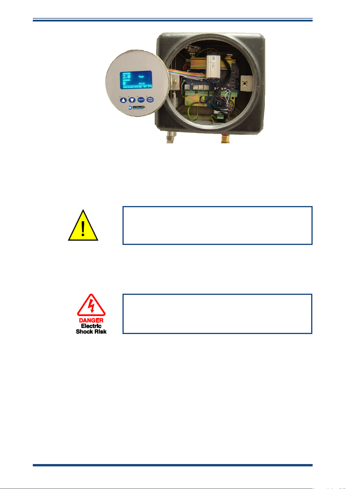
4.1 Enclosure Cover and User Interface
The enclosure cover is part of the flameproof protection for the enclosure and has an
IP66 rating. It should be firmly closed to ensure flameproof integrity and continued
environmental protection. For prolonged and easy operation ensure that the threads
are always lubricated with a light grease. A grub screw is used as a locking device. This
should be loosened before unscrewing the cover counter-clockwise.
The user interface assembly uses two ¼ turn bayonet style fasteners to secure it. These
are finger operated and should be turned clockwise to lock and counter-clockwise to
release. The user interface, once disconnected from the two ¼ turn fasteners, can
be temporarily re-positioned on the instrument by securing the right-hand fastener
in the left-hand mount. This will situate the interface assembly in an overhanging
position outside of the enclosure allowing greater access. If there is insufficient space
to accommodate the overhanging user interface assembly on the left-hand side, it may
be rotated 180° (upside down) and placed on the right-hand side.
28 97090 Issue 16, April 2019
Page 37
Promet EExd User’s Manual
Promet EExd
Process Moisture Analyzer
MAINTENANCE
Figure 23
Ribbon Cable Connection
Always keep the bayonet fittings lightly lubricated. If required, the user interface can
be fully disconnected from the instrument by disconnecting the ribbon cable connection
to the main processor PCB.
All of the procedures below can only be carried out by
first unscrewing the enclosure glass cover and removing
the user interface assembly.
4.2 Replacement of the Moisture Sensor Assembly
The power to the enclosure must be turned off before
any work is carried out in the measurement system
enclosure. Observe de-energize durations.
1. Isolate the incoming sample gas line by CLOSING the sample inlet
isolation valve and allow the system to depressurize. Isolate the power
and observe the de-energize duration.
2. Remove the enclosure window and mount the user interface (see
Section 4.1).
3. Using a 2.5mm hex key remove the M3 cap head screw (1 in Figure 25)
securing the water sensor assembly to the stay bracket.
4. Restrain the sensor assembly. Use a 11mm spanner to loosen and
remove the 2 off 1/8” water dew-point sensor sample pipe connections
(2 in Figure 25).
Michell Instruments 29
Page 38

MAINTENANCE
Promet EExd User’s Manual
2
1
Figure 24
5. Carefully pull the sensor block assembly out of the enclosure. This will
allow access to the two sensor connections and the pressure transducer
connection.
6. Disconnect the ribbon cable connectors from the sensor pcb.
7. Unscrew the connector from the pressure transducer and fully remove
the moisture sensor assembly from the enclosure.
8. Reconnect the sensor and pressure transducer connections to the
replacement moisture sensor assembly. Reposition the assembly on the
stay bracket and secure with the M3 cap head screw.
9. Refit and fully tighten the 1/8” water dew-point sensor sample pipe
connections.
10. To ensure the full requirement of this product’s safety certificate is
maintained, any loosened or disturbed tubework or couplings must be
subject to a gas pressure test and appropriate leak check at 1.5x the
max operating pressure before the full product is re-energized.
Moisture Sensor Assembly Replacement
30 97090 Issue 16, April 2019
Page 39

Promet EExd User’s Manual
4.3 Replacement of the Flow Switch (if fitted)
The power to the enclosure must be turned off before any
work is carried out in the measurement system enclosure.
Observe de-energize durations.
1. Isolate the incoming sample gas line by CLOSING the sample inlet
isolation valve and allow the system to depressurize. NOTE: Always
refer to Appendix G.4 - Special Conditions of Safe Use.
2. Remove the enclosure window and mount the user interface as shown
in Section 4.1.
3. Restrain the flow switch assembly using an 11mm spanner to loosen
and remove the 2 off 1/8” sample pipe connections.
MAINTENANCE
4. Disconnect the 2-wire cable connector from the flow switch to the main
circuit board.
5. Carefully pull the flow switch assembly out of the enclosure.
6. Replacement of the flow switch is simply a reversal of the above
procedure.
7. To ensure the full requirement of this product’s safety certificate is
maintained, any loosened or disturbed tubework or couplings must be
subject to a gas pressure test and appropriate leak check at 1.5x the
max operating pressure before the full product is re-energized.
Michell Instruments 31
Page 40

MAINTENANCE
4.4 Troubleshooting
4.4.1 Error Messages
If a system errors occurs, an error message will appear at the bottom line of the MAIN
Page describing the problem. If more than one system error has occurred, the error
messages associated with those faults will continually scroll in turn.
Promet EExd User’s Manual
MOISTURE
0.5
PRESSURE
0
NO FLOW
Error Message Description and Possible Cause
oCdp
psig
Figure 25
MOISTURE UNDER RANGE
MOISTURE OVER RANGE
TEMPERATURE ERROR
NO FLOW
PRESSURE TRANSMITTER FAILURE
CAL TABLE ERROR
LBMMSCF OUT OF RANGE
INTERNAL HEATER FAULT
Error Message Line
Sensor tile failure
Sensor tile failure
Temperature sensing device of the moisture
sensor has failed
No gas ow through sensor measurement cell see Section 2.7
No pressure detected in the sensor measurement
cell
Fault with sensor calibration data
Calculation of moisture in natural gas cannot be
calculated due to invalid inputs
Fault with the internal temperature control
32 97090 Issue 16, April 2019
Page 41

Promet EExd User’s Manual
4.4.2 Logged Error Codes
This page displays a record of the last six system error codes that have occurred in
order to assist in the diagnosis of any past anomalies. Error codes are only logged at the
end of every measurement cycle and indicate a change in status of single or multiple
errors. For example, if an error code 0004 was logged this would indicate CHANNEL 1
TEMPERATURE ERROR. If an error code of 0000 was next logged this would indicate
that the error had now cleared.
LOGGED ERROR CODES
CODE TIME & DATE
0008 11:10 02/08/12
MAINTENANCE
Figure 26
Logged Error Codes and Error Indication (Modbus Register 35)
Also see Appendix G, Register Configuration C for more details
Error Code Error Message
0000 All previous errors now cleared
0001 Channel 1 moisture sensor under range
0002 Channel 1 moisture sensor over range
0004 Channel 1 temperature device fault
0008 Channel 1 no ow
0010 Channel 1 pressure transmitter failure
0020 Channel 1 LBMMSCF calculation error
0040 Not used
0080 Channel 2 moisture sensor under range
0100 Channel 2 moisture sensor over range
0200 Channel 2 temperature device fault
0400 Channel 2 no ow
0800 Channel 2 pressure transmitter failure
1000 Channel 2 LBMMSCF calculation error
2000 Not used
4000 Internal heater fault
The 4 digit error codes are hexadecimal numbers that are dependent upon the bits set
within the error indication register.
Logged Error Codes
Michell Instruments 33
Page 42

MAINTENANCE
If more than one error has occurred, then the error codes will be added together, e.g.
1) Error Code 0104 =
Error Code 0100 (Channel 2 sensor over range) plus
Error Code 0004 ( Channel 1 temperature device fault) (0100 + 0004 = 0104)
2) Error Code 0C00 =
Error Code 0800 (Channel 2 pressure transmitter fault) plus
Error Code 0040 (Channel 2 no flow ) (0800 + 0400 = 0C00)
Note : In hexadecimal
A = 10
B = 11
C = 12
D = 13
E = 14
F = 15
Promet EExd User’s Manual
4.4.3 Analyzer Status Alarm Relay
Each alarm relay features Normally Open (N/O), Normally Closed (N/C) and Common
(C) contacts.
The process alarm contacts change state when the moisture value is greater than the
alarm set point.
The fault alarm contacts change state when an error associated with the channel occurs,
or when there is a supply failure.
34 97090 Issue 16, April 2019
Page 43

Promet EExd User’s Manual
APPENDIX A
Appendix A
Technical Specifications
Michell Instruments 35
Page 44

APPENDIX A
Appendix A Technical Specications
Main Unit – Measurement Parameters
Channel Conguration Single and dual channel
Moisture Parameters Dew point °C and °F / Pressure
Automatic pressure compensated conversions:
ppmV for natural gas and ideal gas
Moisture Content
Analysis Pressure barg, MPa and psig
Sensor Technology
Sensor Technology Michell Ceramic Moisture Sensor
Measurement Range
Calibration Range
Accuracy
Measured Resolution
Displayed Resolution
Temperature Coecient Algorithm compensation
lb/MMscf and mg/m3 for natural gas
dew point at a pressure input by the user for natural gas & ideal gas
Calculations for natural gas moisture content based on either IS0
18453 or IGT#8 to customer order preference
-120 to +30°Cdp (-184 to +86°Fdp)
1 ppbV to 30,000 ppm
0 to 250 barg (0 to 3625 psig)
-100 to +20°Cdp (-148 to +68°Fdp)
10 ppbV to 23,000 ppm
Dew point: ±1°C between –59.9 & +20°Cdp
(±1.8°F between -75.9 to +68°Fdp)
Moisture content: ±10% of reading
Dew point: ±2°C between –60 & -100°Cdp
(±3.6°F between -76 to -148°Fdp)
Moisture content: ±20% of reading
Analysis Pressure: ±0.25% FS
0.1°C: -80 to +20°Cdp (0.2°F: -112 to +68°Fdp)
1°C: -100 to -80°Cdp (2°F: -148 to -112°Fdp)
Dew point: 0.1°C (0.2°F)
Moisture content: autoscale, 5 digits
MPa and barg: 0.1 (1 psig)
V
V
Promet EExd User’s Manual
HMI
Keyboard/Interface Capacitive touch-screen through glass
Display Vacuum uorescent
A rolling maximum of 150 data logs is available
Each log records time, date, moisture and pressure values for each
Datalogging
Communications and
Output
channel
5 minutes minimum and 60 minutes maximum logging intervals can
be set by the user
Two non-isolated 4-20 per measurement channel
500 Ω maximum load
Range and parameter settable by user
Modbus RTU @ 9600 baud-rate
Alarms: two volt free contacts per channel; one process value and one
instrument status
Also available via Modbus communications
36 97090 Issue 16, April 2019
Page 45

Promet EExd User’s Manual
APPENDIX A
Enclosure
Main Unit Enclosure
Type Flameproof EExd
Construction Cast copper-free aluminum
Finish Chromate primer, Polyester P9010 powder coated (black) Meets BS3900
Internal temperature control for condensation protection and stable
analysis conditions
General
Operating Pressure Max. 138 barg (2000 psig)
Sample Connections 1/8” NPT(F)
Sample Flow Rate 0.5 to 5 Nl/min (1.06 to 10.6 scfh)
Sample Flow Alarm Optional
Power Supply 90 to 260 V AC, 47/63 Hz, 180 W - Main Unit
353 x 310 x 245mm (13.8 x 12.2 x 9.6”) (h x w x d)
Dimensions
Weight Analyzer - 21kg (46lbs)
Operating Environment
500 x 500 x 245mm (19.7 x 19.7 x 9.6”) (including installation
clearance) (h x w x d)
Indoor/Outdoor -20 to +60°C (-4 to +140°F)
Max 95%RH
Shaded location
IP66/NEMA4
Hazardous Area Certification
ATEX
II2G Exd IIB + H2 Gb T5 (Tamb -40°C to +44°C)
T4 (Tamb -40°C to +60°C)
IECEX
Exd IIB + H2 Gb T5 (Tamb -40°C to +44°C)
T4 (Tamb -40°C to +60°C)
Certication Codes
Pattern Approvals GOST-R, GOST-K
cCSAus
Class I, Division 1, Groups B, C & D T5 (Tamb -40°C to +44°C)
T4 (Tamb -40°C to +60°C)
TR CU 012
1Exd IIB + H2 Gb T5 (Tamb -40°C to +44°C)
T4 (Tamb -40°C to +60°C)
Michell Instruments 37
Page 46

APPENDIX A
270mm 10.63"
318mm 12.52"
355mm [13.9"]
245mm 9.65"
290mm [11.41"]
4 o M12 (1/2")
Clearance
Enclosure Breather
Flame Arrestor
Do NOT obscure
Sample Out - Channel 2 (Optional)
Flame Arrestor
1/8" NPT Female (ATEX/IECEx/CSA)
Sample In - Channel 2 (Optional)
Flame Arrestor
1/8" NPT Female (ATEX/IECEx/CSA)
Sample in - Channel 1
Flame Arrestor
1/8" NPT Female (ATEX/IECEx/CSA)
Sample out - Channel 1
Flame Arrestor
1/8" NPT Female (ATEX/IECEx/CSA)
310mm [12.20"]
Cable Entry Glands
3 o M20 (ATEX)
3 o 1/2" NPT (CSA)
A.1 Mounting Drawing
Promet EExd User’s Manual
Figure 27
Mounting Drawing
38 97090 Issue 16, April 2019
Page 47

Promet EExd User’s Manual
A.2 Pipework Connections
PRESSURE
TRANSMITTER
APPENDIX A
CHANNEL 1 CHANNEL 2
MICHELL MOISTURE
SENSOR
PRESSURE
TRANSMITTER
MICHELL MOISTURE
SENSOR
GAS SAMPLING BLOCK
FLOW
SWITCH
(optional)
FLAME
ARRESTORS
GAS IN GAS OUT
FLAME
BREATHER
ARRESTOR
GAS SAMPLING BLOCK
FLOW
SWITCH
(optional)
FLAME
ARRESTORS
GAS IN GAS OUT
Figure 28
Pipework Connections
Michell Instruments 39
Page 48

APPENDIX A
A.3 System Wiring Diagram
AL3AL2AL1 AL4 COMMS Channel 1 Channel 2
NC C NO NC C NO
1 2 3 4 5 6
NC C NO NC C NO
7 8 9 1011
PL16
12
Promet EExd User’s Manual
mA1+
mA1-
mA2+
B A GND
PL20 PL15 PL14 PL19
13 14 15
16 17 18 19 20 21 22 23
L E N
mA2-
mA3+
mA3-
mA4+
mA4-
Enclosure wall
Gland
Cable screen
Figure 29
System Wiring Diagram
EExd Stopping Glands MUST be used for ATEX/IECEx
installations.
Refer to the separate installation & maintenance information
sheet supplied.
40 97090 Issue 16, April 2019
Page 49

Promet EExd User’s Manual
APPENDIX B
Appendix B
Variable Definitions
Michell Instruments 41
Page 50

APPENDIX B
Appendix B Variable Denitions
From the VARIABLES page, press the Up () or Down () buttons to highlight the
variable required. Press the SELECT button to enter the range/options area. Change the
variable using the Up () or Down () buttons and press the SELECT button to set
the new option. Scroll down to the next variable required. To return to the MAIN Page
press the MENU/MAIN button.
Variable: UNITS (single channel), CHN1, CHN2
Adjustable Range/Options: Ppm(v) IG, DP@PR idl Gas, DP@PR Nat Gas, mgm-3
Gas, Ppm(v) NG, LBMMSCF, Dew point
Description: The moisture units for Channels 1 and 2.
i. Dew point can be displayed in either °C or °F whether it is at
the sample pressure or if it is calculated to another.
ii. When calculating the dew point at another pressure (DP @
PR) the apply option below is enabled to allow the entry of
the pressure at which the dew point is to be calculated at.
Promet EExd User’s Manual
Nat
iii. mA1 and mA3 outputs represent the setting of Channel 1
and 2 respectively.
NOTE: Changing the units clears the data logging memory and resets the
analog outputs and alarm settings.
Variable: apply
Adjustable Range/Options: Pressure value in the units of pressure
Description: The pressure value entered here is the pressure value at which dew point
will be calculated at, if DP@PR Nat Gas or DP@PR IDL Gas is selected as
the unit of moisture measurement. If any other unit is selected then the
option will show n/a.
Variable: alarm
Adjustable Range/Options: -100 to +100°C, 0 to 1200 LBMMSCF, 0.0 to 3000.0
Ppm(v), 0 to 1000mgm-3
Description: The set point for the process alarm that activates the channel alarm relay
when the moisture value exceeds it.
Variable: OP1MIN (single channel), OP3MIN
Adjustable Range/Options: -100 to +100°C, 0 to 1200 LBMMSCF, 0.0 to 3000.0
Ppm(v), 0 to 1000mgm-3
Description: The minimum moisture value that 4 mA represents for the respective
output.
42 97090 Issue 16, April 2019
Page 51

Promet EExd User’s Manual
Variable: OP2MIN (single channel), OP4MIN
Adjustable Range/Options: 0.1 - 25.0 MPa/0 - 250 barg/0 - 3000 psig (for Pressure)
-100 to +100°C/-148 to +212°F (for Dew point)
Description: The minimum dew-point or pressure value that 4 mA represents for the
respective output.
Variable: OP1MAX (single channel), OP3MAX
Adjustable Range/Options: -100 to +100°C, 0 to 1200 LBMMSCF, 0.0 to 3000.0
Description: The maximum moisture value that 20 mA represents for the respective
output.
Ppm(v), 0 to 1000mgm-3
APPENDIX B
Variable: OP2MAX (single channel), OP4MAX
Adjustable Range/Options: 0.1 - 25.0 MPa/0 - 250 barg/0 - 3000 psig (for Pressure)
-100 to +100°C/-148 to +212°F (for Dew point)
Description: The maximum dew-point or pressure value that 20 mA represents for the
respective output.
Variable: °C / °F
Adjustable Range/Options: Celsius or Fahrenheit
Description: Dew-point unit of measurement, in °C or °F.
NOTE: Changing the temperature units will set the default values and
clear the logged data.
Variable: Pressure
Adjustable Range/Options: MPa, barg, psig
Description: Units of measurement for the pressure values. psig, barg or MPa may be
selected.
NOTE: Changing the pressure units will clear the logged data.
Michell Instruments 43
Page 52

APPENDIX B
Variable: TIME
Adjustable Range/Options: hh:mm; 00:00 to 23:59
Description: The real-time clock in 24hr format. Minutes and hours may be adjusted.
Variable: DATE
Adjustable Range/Options: Day: 01-31, Month: 01-12, Year: 00-99
Description: The date. Format: ddmmyy. To adjust the day, highlight the DATE field,
Promet EExd User’s Manual
Pressing either the Up () or Down () buttons will increment or
decrement the minute’s field and the corresponding hours field will change
automatically.
press SELECT (a ‘d’ should appear to the right of the year value). Use the
Up () or Down () buttons to adjust. To adjust the month and year,
press SELECT again (an ‘m’ should appear to the right of the year value).
Use the Up () or Down () buttons to adjust the month. As the month
changes, the year field will change automatically. Press SELECT to finish.
Variable: OP2/4 PARAM
Adjustable Range/Options: Measured Dew point, Pressure
Description: The parameter selected for mA2 (and mA4) outputs.
Variable: LOG INT’VAL
Adjustable Range/Options: 10 to 60 in intervals of 10 minutes
Description: Sets the interval between the logged data readings.
Variable: RESET LOG
Adjustable Range/Options: select, done
Description: Resets the logging statistics so that the variation in measurements can be
recorded from a user-defined start point. When the RESET LOG variable
is highlighted press the SELECT button - the option will go from select to
done.
44 97090 Issue 16, April 2019
Page 53

Promet EExd User’s Manual
Variable: INST ADDR
Adjustable Range/Options: 01 to 31
Description: Unique instrument address for networking. This address is used by the
Modbus protocol to specify the location of the Promet EExd instrument in
the network.
Variable: INT TEMP SP
Adjustable Range/Options: -20 to +60°C
Description: Sets the set point for the internal heater.
Variable: SET DEFAULT
Adjustable Range/Options: select, done
APPENDIX B
Description: Sets instrument to default configuration. The default values for all the
variables and parameters are set.
The default values are:
Units/CHN1/2
apply
alarm
OP1 Min
OP1 Max
OP2 Min
OP2 Max
OP3 Min
OP3 Max
OP4 Min
OP4 Max
°C/°F
Pressure
LOG INT
INST ADD
INT TEMP SP
Dew point
N/A
0°C
-100°C
+20°C
0 barg
250 barg
-100°C
+20°C
0 barg
250 barg
Celcius
barg
10mins
01
+20°C
Michell Instruments 45
Page 54

APPENDIX C
Promet EExd User’s Manual
Appendix C
Software
46 97090 Issue 16, April 2019
Page 55

Promet EExd User’s Manual
Appendix C Software
Software is available for the Promet EExd to provide full remote control of up to 31
instruments. It provides access to all readable and write-able registers as described in
Appendix E, along with charting and data logging facilities.
The Promet EExd application software provides the user with advanced acquisition,
logging and charting features for full remote control and monitoring of the Promet EExd.
With this application software it is possible to:
• View all main parameters of interest
• Modify parameters
• Record parameters to a virtual chart recorder
• Record parameters to a file
APPENDIX C
• Acquire data from up to 31 process instruments
• Perform remote diagnostics
• Acquire OPC enabled remote access to all parameters and
variables
C.1 System Requirements
For a desktop computer, the following specification applies:
• Microsoft Windows 7, 98SE, ME, 2000 or XP operating system
• Spare RS232 port (normally labelled COM1, COM2 etc)
• Minimum of 64 MB of RAM (128M or higher recommended)
• Minimum of 200 MB of free hard disk space (application
approximately 3.5 MB, spare for log files)
• Intel Pentium II class processor, 200 MHz or higher
Michell Instruments 47
Page 56

APPENDIX D
Promet EExd User’s Manual
Appendix D
Modbus RTU
Communications
48 97090 Issue 16, April 2019
Page 57
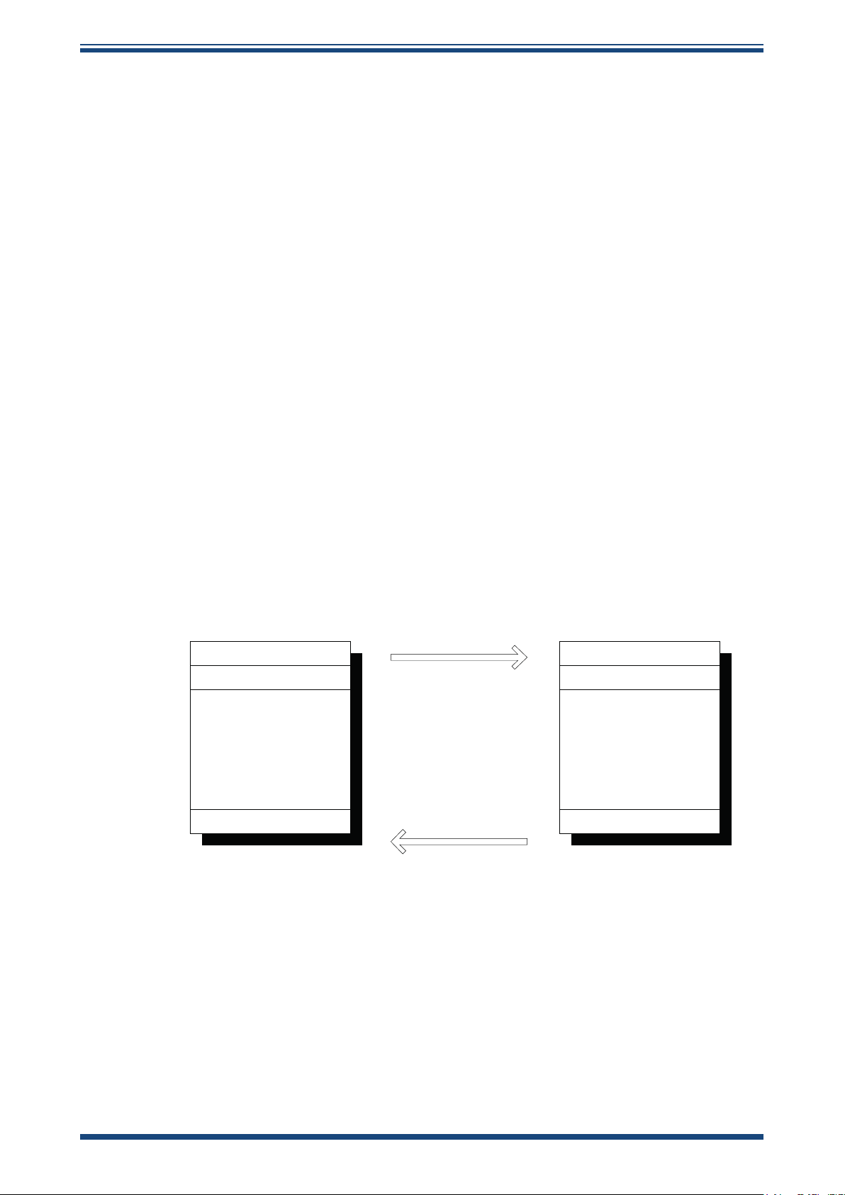
Promet EExd User’s Manual
Device Address
Function Code
Data Bytes
CRC
Device Address
Function Code
Data Bytes
CRC
Query Message from Master
Response From Slave
MASTER
SLAVE
Appendix D Modbus RTU Communications
D.1 Introduction
Implemented within the Promet EExd are Modbus RTU communications that enable
remote access to the instrument’s configuration and data logging facilities. This protocol
offers two-way communication between a PC or PLC known as the master, to one or
more instruments known as slaves. Communication is achieved by the master reading
or writing to registers within the slave. The slave acts upon information contained
within the registers that can be written, and the master obtains measured values and
status information from the register that can be read. Appendix E lists these registers
and Appendix G specifies the number or data formats that apply to each register.
D.2 Modbus RTU Basics
Modbus RTU operates on a Query-Response Cycle (see the diagram below). The function
code in the query tells the addressed slave device which actions to perform using the
information contained in the data bytes. The error check field provides a method for the
slave to validate the integrity of the message contents.
APPENDIX D
If the slave makes a normal response, the function code in the response is an echo of
the function code in the query and the data bytes will contain data collected by the
slave, such as register values or status information. If an error occurs, the function code
is incremented by 80H. This indicates that the response is an error response, known as
an exception, and the data bytes contain a code to describe the error. The error check
field allows the master to confirm that the message contents are valid.
D.3 Physical Layer
Michell Instruments 49
The physical connection from the master to the Promet EExd uses 2-wire RS485 plus
a ground connection. Data lines A, B and ground are connected to communication
connectors within the instrument. The serial port protocol is as follows:
Baud Rate: 9600
Start Bit: 1
Data bits: 8
Parity: None
Stop bit: 2
Page 58

APPENDIX D
D.4 Termination Resistor
A 120 Ω termination resistor is provided on the instrument’s circuit board for systems
that require it. To connect the resistor, place the link provided across JMP2.
D.5 Register Map
The following tables describe the instrument registers with their address location,
Modbus function and the number format.
System Parameters
Promet EExd User’s Manual
Address
dec
0 0000* Instrument Address R/W 0001H F
1 0001 Sensor 1 Moisture Value – Hi Word R L
2 0002 Sensor 1 Moisture Value – Lo Word R L
3 0003 Sensor 1 Ambient Temperature R H
4 0004 Status R D
5 0005 Sensor 2 Moisture Value – Hi Word R L
6 0006 Sensor 2 Moisture Value – Lo Word R L
7 0007 Time to next log Mins + Secs R I
8 0008 Sensor 2 Ambient Temperature R H
9 0009 Sensor 1 Pressure value R H
10 000A Sensor 2 Pressure value R H
11 000B Sensor 1 Moisture Setting R/W 0001H B
12 000C* mA1 output maximum value (sensor 1 moisture) R/W 0032H K
13 000D* mA1 output minimum value (sensor 1 moisture) R/W FFCEH K
14 000E* mA2 output maximum value (sensor 1 pressure) R/W 0BB8H M
15 000F* mA2 output minimum value (sensor 1 pressure) R/W 0000H M
16 0010* Sensor 2 Moisture Setting R/W 0001H B
17 0011* mA3 output maximum value (sensor 2 moisture) R/W 0032H F
18 0012* mA3 output minimum value (sensor 2 moisture) R/W FFCEH K
19 0013* Logging Interval R/W 000AH I
20 0014* mA4 output maximum value (sensor 2 pressure) R/W 0BB8H M
21 0015* mA4 output minimum value (sensor 2 pressure) R/W 0000H M
22 0016* Sensor 1 Alarm Set Point R/W 0000H K
23 0017* Sensor 2 Alarm Set Point R/W 0000H K
24 0018* RTC Year (val1) + Month (val2) R/W I
25 0019* RTC Date (val1) + Hours (val2) R/W I
26 001A* RTC Mins (val1) + Secs (val2) R/W I
27 001B* Sensor 1 Pressure Set (DP @ Pressure) R/W H
28 001C* Sensor 2 Pressure Set (DP @ Pressure) R/W H
29 001D Units/ Command R/W 000000H E
30 001E Moisture Sensor 1 – Batch Number R I
31 001F Moisture Sensor 1 – Serial Number R I
32 0020 Moisture Sensor 1 - Year R I
33 0021 Moisture Sensor 1 – Month and day R I
34 0022 Moisture Sensor 1– Hours Of Operation R F
Address
hex
Function
Read/
Write
Default
Value
Register
Cong-
uration
50 97090 Issue 16, April 2019
Page 59

Promet EExd User’s Manual
APPENDIX D
Address
dec
35 0023 Error Indicator R C
36 0024 Not Used
37 0025 Internal Temperature R A
38 0026 Internal Temp Set Point R/W 07D0H A
39 0027 Moisture Sensor 2 – Batch Number R I
40 0028 Moisture Sensor 2 – Serial Number R I
41 0029 Moisture Sensor 2 - Year R I
42 002A Moisture Sensor 2 – Month and day R I
43 002B Moisture Sensor 2 – Hours Of Operation R F
44 002C Not Used
45 002D Moisture max – Hi Word – Sensor 1 R L
46 002E Moisture max – Lo Word – Sensor 1 R L
47 002F Occurred @ day (val1) + month (val2) R J
48 0030 Occurred @ hour (val1) + min (val2) R J
49 0031 Moisture min – Hi Word – Sensor 1 R L
50 0032 Moisture min – Lo Word – Sensor 1 R L
51 0033 Occurred @ day (val1) + month (val2) R J
52 0034 Occurred @ hour (val1) + min (val2) R J
53 0035 Moisture average Hi Word – Sensor 1 R L
54 0036 Moisture average Lo Word – Sensor 1 R L
55 0037 Sensor 1 Measured dew point - Hi Word R L
56 0038 Sensor 1 Measured dew point - Lo Word R L
57 0039 Instrument Type R 0002H I
58 003A Firmware Version Number R I
59 003B Sensor 2 Measured dew point - Hi Word R L
60 003C Sensor 2 Measured dew point - Lo Word R L
61 003D Moisture max – Hi Word – Sensor 2 R L
62 003E Moisture max – Lo Word – Sensor 2 R L
63 003F Occurred @ day (val1) + month (val2) R J
64 0040 Occurred @ hour (val1) + min (val2) R J
65 0041 Moisture min – Hi Word – Sensor 2 R L
66 0042 Moisture min – Lo Word – Sensor 2 R L
67 0043 Occurred @ day (val1) + month (val2) R J
68 0044 Occurred @ hour (val1) + min (val2) R J
69 0045 Moisture average Hi Word – Sensor 2 R L
70 0046 Moisture average Lo Word – Sensor 2 R L
71 0047 Not Used
72 0048 Not Used
73 0049 Pressure max – Sensor 1 R H
74 004A Occurred @ day (val1) + month (val2) R J
75 004B Occurred @ hour (val1) + min (val2) R J
76 004C Pressure min – Sensor 1 R H
77 004D Occurred @ day (val1) + month (val2) R J
78 004E Occurred @ hour (val1) + min (val2) R J
79 004F Pressure average – Sensor 1 R H
80 0050 Pressure max – Sensor 2 R H
Address
hex
Function
Read/
Write
Default
Value
Register
Cong-
uration
Michell Instruments 51
Page 60

APPENDIX D
Promet EExd User’s Manual
Address
dec
81 0051 Occurred @ day (val1) + month (val2) R J
82 0052 Occurred @ hour (val1) + min (val2) R J
83 0052 Pressure min – Sensor 2 R H
84 0053 Occurred @ day (val1) + month (val2) R J
85 0054 Occurred @ hour (val1) + min (val2) R J
86 0055 Pressure average – Sensor 2 R H
87 0056 Not Used
88 0057 Not Used
Address
hex
Function
Read/
Write
Default
Value
Register
Cong-
uration
52 97090 Issue 16, April 2019
Page 61

Promet EExd User’s Manual
256 0100 Date Day + Month @ t 0 R J
257 0101 Time Hours + Mins @ t 0 R J
258 0102 Moisture 1 Hi Word @ t 0 R L
259 0103 Moisture 1 Lo Word Pressure @ t 0 R L
260 0104 Pressure 1 @ t 0 R H
261 0105 Moisture 2 Hi Word @ t 0 R L
262 0106 Moisture 2 Lo Word Pressure @ t 0 R L
263 0107 Pressure 2 @ t 0 R H
264 0108 Date Day + Month @ t 0 R J
265 0109 Time Hours + Mins @ t 0 R J
266 010A Moisture 1 Hi Word @ t 0 R L
267 010B Moisture 1 Lo Word Pressure @ t 0 R L
268 010C Pressure 1 @ t 0 R H
269 010D Moisture 2 Hi Word @ t 0 R L
270 010E Moisture 2 Lo Word Pressure @ t 0 R L
271 010F Pressure 2 @ t 0 R H
APPENDIX D
Data Logging
1449 05A9 Date Day + Month @ t 0 R J
1450 05AA Time Hours + Mins @ t 0 R J
1431 05AB Moisture 1 Hi Word @ t 0 R L
1452 05AC Moisture 1 Lo Word Pressure @ t 0 R L
1453 05AD Pressure 1 @ t 0 R H
1451 05AE Moisture 2 Hi Word @ t 0 R L
1455 05AF Moisture 2 Lo Word Pressure @ t 0 R L
1456 05B0 Pressure 2 @ t 0 R H
Note: To download logged data, calculate the start address by the following formula:
(sample number x 8) + 256. Start addresses that do not coincide with the first register
of a sample will generate an exception response. Due to the maximum limit of 125
data registers that can be read in one transmission, as defined by the Modbus RTU
standard, only 20 samples can be downloaded at any one time. Therefore, eight reads
are required to download all 150 samples.
Michell Instruments 53
Page 62

APPENDIX E
Promet EExd User’s Manual
Appendix E
Modbus RTU Details
54 97090 Issue 16, April 2019
Page 63

Promet EExd User’s Manual
Appendix E Modbus RTU Details
E.1 Message Framing
APPENDIX E
START ADDRESS
3.5t 1 byte 1 byte n x bytes 2 bytes 3.5t
FUNCTION
CODE
DATA CRC END
Start and End
The message begins and ends with a silent delay of 3.5 character times at the baud
rate of the network.
Address
The first byte transmitted is the address of the instrument, which has a range of 1 to
247 or 01H to F7H. The master addresses an instrument by placing the address in the
address byte and, if matched, a Promet EExd will response to the message, otherwise
it will be ignored. See Appendix E on setting the address.
Function Code
The function code tells the Promet EExd which operation is to be performed on the data
in the following data bytes. The only valid codes are 03 (Read Holding Registers) or
06 (Write To Single Register) as these are the only two implemented.
An exception can occur if the message contains an unsupported function code, an illegal
data address or an illegal data value. If this occurs, the function code is incremented
by 80H and the data bytes returned are set to a value that describes the error. See
Appendix F.2.
Data Bytes
The data bytes within the message from the master contain additional information that
the Promet EExd must use to perform the action defined in the function code, such as
the starting register address and the number of registers to be retrieved.
CRC
The CRC is a 2-byte error check value from the result of a Cyclical Redundancy Check
calculation performed on the message contents. The CRC is appended to the message
as the last field in the message, whereby the low-order byte is appended first, followed
by the high-order byte.
Michell Instruments 55
Page 64

APPENDIX E
ENTRY
Address in message = Instrument Address
Function code supported
Exception Code = 01
0x0000 <= Quantity of Registers <= 0X007d
Exception Code = 03
Exception Code = 02
Starting Address = OK
AND
Starting Address + Number of Registers = OK
Request Processing
Reading Registers = OK
Exception Code = 04
Sends Response with data
Sends Exception Response
EXIT
E.2 Implemented Functions
03 Read Holding Registers
This function code is used to read the contents of a contiguous block of holding registers,
where the master specifies the starting address and the number of registers to be read.
Figure 32 shows the state diagram of how the message is processed with the exceptions
that may be raised.
Promet EExd User’s Manual
56 97090 Issue 16, April 2019
Figure 30
Reading Holding Registers State Diagram
Page 65

Promet EExd User’s Manual
The table below is an example of a message sent by the master, to read the time to the
next log (register 7) and Channel 2 gas temperature (register 8). The message shows
a master addressing a Promet EExd with a slave address of 01H and a Modbus function
of 03H that informs the Promet EExd that it wishes to read two registers starting from
address 07H. Bytes 3 & 4 hold the starting address and bytes 5 & 6 hold the number of
registers to be read. Bytes 7 & 8 contain the CRC code that is calculated using bytes 1
to 6 as represented below.
Byte No Meaning Value
1 Slave Address 01H
2 MODBUS function code 03H
3 Starting Address MSB 00H
4 Starting Address LSB 07H
5 No of points MSB 00H
6 No of points LSB 02H
7 CRC Lo Byte ??H
8 CRC Hi Byte ??H
APPENDIX E
Read Request Message
In response to the above message, the Promet EExd may transmit the following message.
Byte No Meaning Value
1 Slave Address 01H
2 MODBUS function code 03H
3 Byte Count 04H
4 Data MSB 05H
5 Data LSB 26H
6 Data MSB 00H
7 Data LSB FAH
8 CRC Lo Byte ??H
9 CRC Hi Byte ??H
Read Response Message
This response repeats the address of the Promet EExd and the function code, along
with the byte count, the data and the CRC. In this example, the request asked for the
values from two registers. Therefore, the number of bytes returned is four. The value of
register 7 is contained in bytes 4 & 5 and the value of register 8 in bytes 6 & 7. Register
7 = 5m 26s and register 7 = 00FA = 252 = 25.2°C in this example. Any errors within
the data of Read Request Message will result in an exception being raised.
Michell Instruments 57
Page 66

APPENDIX E
06 Write to Single Register
This function code is used to write a 16 bit value into a single register, whereby the
master specifies the address and the value to be written. Figure 33 shows the state
diagram of how the message is processed with the exceptions that may be raised.
Promet EExd User’s Manual
ENTRY
Address in message = Instrument Address
Function code supported
Exception Code = 01
Exception Code = 03
0x0000 <= Register Value<= 0xFFFF
Register Address == OK
Exception Code = 02
Request Processing
Write To Single Register = OK
Exception Code = 04
Mirrors Request
Sends Exception Response EXIT
Figure 31
Write Single Register State Diagram
58 97090 Issue 16, April 2019
Page 67

Promet EExd User’s Manual
The table below shows the data bytes in a Write To Single Register message. Bytes 1
to 4 contain the address of the Promet EExd, Modbus function, starting register address
and the data value to be written. In this example a master sends FC18H to address
0015H, to a Promet EExd with an address of 01H. The CRC is calculated using the data
in bytes 1 to 6.
Byte No Meaning Value
1 Slave Address 01H
2 MODBUS function code 06H
3 Starting Address MSB 00H
4 Starting Address LSB 15H
5 Data MSB FCH
6 Data LSB 18H
7 CRC Lo Byte ??H
8 CRC Hi Byte ??H
APPENDIX E
Write Single Register Request and Response
The normal response from the Promet EExd is to re-transmit the received message.
However, if the data within the message is incorrect then an exception response will be
transmitted.
Michell Instruments 59
Page 68

APPENDIX E
E.3 Exceptions
A message request from the master will raise an exception response from the slave
(Promet EExd) if:
i. the function code is unsupported
ii. the register quantity > 127 (0x007D)
iii. the register address is invalid
iv. the register address + the quantity of register is invalid
v. an error occurred while performing the function
The exception response will contain the function code incremented by 80H and the
exception code.
The table below lists the codes supported, along with an explanation of each code.
Promet EExd User’s Manual
Code Name Meaning
01 ILLEGAL FUNCTION
02 ILLEGAL DATA ADDRESS
03 ILLEGAL DATA VALUE
04 SLAVE DEVICE FAILURE
Example of an Exception Response that reads a discrete inputs message generating an
illegal function exception.
Byte Meaning Value
1 Slave Address 01H
2 Function 82H
3 Exception Code 01H
4 CRC ??
The function code received in the query is
not an allowable action for the slave
The data address received in the query is not
allowable. More specically, the combination
of starting address and number of registers
is invalid for the slave
A value contained in the query data eld is
not an allowable value for the slave
An unrecoverable error occurred while
the slave was attempting to perform the
requested action
The example above shows the function code (02H) sent in the request has been
incremented by 80H with the exception code 01H included as the data within the
message.
60 97090 Issue 16, April 2019
Page 69

Promet EExd User’s Manual
APPENDIX F
Appendix F
Register Number Formats
Michell Instruments 61
Page 70

APPENDIX F
Appendix F Register Number Formats
Register Configuration A
15 14 13 12 11 10 9 8 7 6 5 4 3 2 1 0
r r r r r r r r r r r r r r r r
Sign bit = 1 for –ve values (signed int)
7FFF = 327.67
8000 = -327.68
The value in bits (15 to 0) + 1 is divided by 100 to give 0.01 resolution for dew-point
and temperature values.
Value
Promet EExd User’s Manual
Register Configuration B – Sensor Moisture Value
15 14 13 12 11 10 9 8 7 6 5 4 3 2 1 0
r/w r/w r/w r/w r/w r/w r/w r/w r/w r/w r/w r/w r/w r/w r/w r/w
N/A
N/A
N/A
N/A
N/A
N/A
N/A
N/A
N/A
lb/MMscf
for Natural Gas
3
Ppm(v) for Ideal Gas
Dp @ Pressure for Ideal Gas
The bit settings are mutually exclusive.
Dp @ Pressure for Natural Gas
m/gm
Ppm(v) for Natural Gas
Dp
62 97090 Issue 16, April 2019
Page 71

Promet EExd User’s Manual
Register Configuration C – Error Conditions
15 14 13 12 11 10 9 8 7 6 5 4 3 2 1 0
r r r r r r r r r r r r r r r r
Bit HEX Error Condition
0 0001 Sensor 1 under range
1 0002 Sensor 1 over range
2 0004 Sensor 1 temperature fault
3 0008 Sensor 1 No ow
4 0010 Sensor 1 pressure transmitter failure
5 0020 Sensor 1 LBMMSCF calculation error
6 0040 NOT USED
7 0080 Sensor 2 under range
8 0100 Sensor 2 over range
9 0200 Sensor 2 temperature fault
10 0400 Sensor 2 No ow
11 0800 Sensor 2 pressure transmitter failure
12 1000 Sensor 2 LBMMSCF calculation error
13 2000 NOT USED
14 4000 Internal heater fault
APPENDIX F
Register Configuration D - Status Word
15 14 13 12 11 10 9 8 7 6 5 4 3 2 1 0
r r r r r r r r r r
N/A
N/A
N/A
N/A
N/A
1 = ON or Fitted
0 = OFF or Not Fitted
N/A
Process Alarm 2
Flow Channel 2
Process Alarm 1
N/A
Flow Channel 1
Sensor 1 Fitted
Sensor 2 Fitted
N/A
N/A
N/A
Michell Instruments 63
Page 72

APPENDIX F
Register Configuration E - Units Command
15 14 13 12 11 10 9 8 7 6 5 4 3 2 1 0
N/A
N/A
N/A
N/A
N/A
N/A
N/A
N/A
Promet EExd User’s Manual
w w w r/w r/w r/w r/w
N/A
N/A
MPa
Reset Logging
Reset Defaults
IGT/ ISO 0 = IGT
Psig/barg 0 = psig
1 = ON / Fitted / Initiate
0 = OFF or Not Fitted
Register Configuration F
15 14 13 12 11 10 9 8 7 6 5 4 3 2 1 0
r/w r/w r/w r/w r/w r/w r/w r/w r/w r/w r/w r/w r/w r/w r/w r/w
Unsigned integer. Range = 0 to 65535
°C/°F 0 = °C
Register Configuration H
15 14 13 12 11 10 9 8 7 6 5 4 3 2 1 0
r r r r r r r r r r r r r r r r
Sign bit = 1 for –ve values (signed int)
7FFF = 3276.7
8000 = -3276.8
The value in bits (15 to 0) + 1 is divided by 10 to give 0.1 resolution for dew-point and
temperature values.
Value
64 97090 Issue 16, April 2019
Page 73

Promet EExd User’s Manual
Register Configuration I
15 14 13 12 11 10 9 8 7 6 5 4 3 2 1 0
r/w r/w r/w r/w r/w r/w r/w r/w r/w r/w r/w r/w r/w r/w r/w r/w
Val 1
Val 1 & 2 are in BCD, therefore 10H = 10, 58H = 58 and 09H = 9 etc. As a result A to
F are not valid values.
Values for Cycle Time and Max Cool Time are in units of 5 mins.
Register Configuration J
15 14 13 12 11 10 9 8 7 6 5 4 3 2 1 0
r/w r/w r/w r/w r/w r/w r/w r/w r/w r/w r/w r/w r/w r/w r/w r/w
Day or Hours
APPENDIX F
Val 2
Minutes or Month
Values in HEX i.e. 17th March = 1103H
Register Configuration K – signed int
15 14 13 12 11 10 9 8 7 6 5 4 3 2 1 0
r r r r r r r r r r r r r r r r
Value
Sign bit = 1 for –ve values (signed int)
7FFF = 32767
8000 = -32768
Register Configuration L - Floating Point Representation
The humidity values for sensors 1 & 2 are represented in IEEE-754 single precision
floating point format, in order to cater for the wide range in the value of ppmV. This
format is ‘Big Ended’ which means that the High byte is at a lower address in memory
than the Lo byte, and is represented as such in the register memory map. The IEEE-754
format is shown below.
Bit 31
Sign bit
0 = +
1 = -
Bits 30 to 23
Exponent Field
Has a +127 bias value
Bits 22 to 0
mantissa
Decimal representation of binary
Where 1.0 ≤ value < 2.0
Michell Instruments 65
Page 74

APPENDIX F
Examples of floating point to HEX are shown below.
1) +10.3
sign bit = 0
Exponent = 3, therefore exponent field = 127 + 3 = 130, and bits 30 to 23 = 10000010
Mantissa = 1.2875 which in binary representation = 1 .01001001 1001 1001 1001 101
Adjusting the mantissa for the exponent moves the decimal point to the right if positive
and to the left if negative.
As the exponent is = 3 then the mantissa becomes = 1010.0100 1100 1100 1100 1 101,
therefore:-
1010 = (1x23) + (0x22) + (1x21 ) + (0x20) = 10 and
0100 1100 1100 1100 1101 = (0x2-1) + (1x2-2) + -- + (1x2
Therefore the word value = 0100 0001 0010 0100 1100 1100 1100 1101
= 4124CCCD
Promet EExd User’s Manual
-20
) = 0.3
Consequently, for sensor 1 register 0001 = 4124 and register 0002 = CCCD
2) - 0.0000045
sign bit = l
Exponent = -18, therefore exponent field = 127 + (-18) = 109, and bits 30 to 23 = 01101101
Mantissa = 1.179648 which in binary representation = 1 .00101101111111010110101
i.e. (1x2
-18
) + (1x2
-21
) + (1x2
-23
) etc = 0.0000045
Therefore the word value = 1011 0110 1001 0110 1111 1110 1011 0101
= B696FEB5
Consequently, for sensor 1 register 0001 = B696 and register 0002 = FEB5
Register Configuration M
15 14 13 12 11 10 9 8 7 6 5 4 3 2 1 0
r/w r/w r/w r/w r/w r/w r/w r/w r/w r/w r/w r/w r/w r/w r/w r/w
Unsigned integer / 10
Range = 0 to 6553.5
66 97090 Issue 16, April 2019
Page 75

Promet EExd User’s Manual
APPENDIX G
Appendix G
Hazardous Area
Certification
Michell Instruments 67
Page 76

APPENDIX G
!
Appendix G Hazardous Area Certication
The Promet EExd is certified compliant to the ATEX Directive (2014/34/EU) and IECEx
for use within Zone 1 and Zone 2 Hazardous Areas and has been assessed so by Element
Materials Technology LTD (Notified Body 0891).
The Promet EExd is certified compliant to North American Standards (USA and Canada)
for use within Class I, Division 1, Groups B (USA only), C and D Hazardous Locations
and has been assessed so by CSA.
G.1 Product Standards
This product conforms to the Standards:
EN60079-0:2012/A11:2013 IEC60079-0:2011
EN60079-1:2007 IEC60079-1:2007
CSA C22.2 No. 142-M1987 UL508
C22.2 No. 30-M1986 UL1203
Promet EExd User’s Manual
G.2 Product Certification
This product is attributed with the product certification codes:
ATEX
II2G Exd IIB + H2 Gb T5 (Tamb -40°C to +44°C)
T4 (Tamb -40°C to +60°C)
IECEX
Exd IIB + H2 Gb T5 (Tamb -40°C to +44°C)
T4 (Tamb -40°C to +60°C)
cCSAus
Class I, Division 1, Groups B, C & D T5 (Tamb -40°C to +44°C)
T4 (Tamb -40°C to +60°C)
G.3 Global Certificates/Approvals
ATEX TRAC11ATEX21320X
IECEx TRC11.0011X
cCSAus 1701657
These certificates can be viewed or downloaded from our website at:
http://www.michell.com
Special attention should be paid to the
for Safe Use
and the
certificates shown on the website.
Conditions of Certification
Special Conditions
listed in the
68 97090 Issue 16, April 2019
Page 77

Promet EExd User’s Manual
G.4 Special Conditions of Use
1. Do not open when an explosive gas atmosphere may be present.
2. External cables shall be compatible with a temperature of 93°C (T5) or 109°C
(T4).
3. Maximum process pressure shall not exceed 138 barg.
4. Maximum combined process flow into the enclosure shall not exceed 1.5 LPM.
5. All process lines shall be purged to ensure the process gas or liquid is above its
upper explosive limit before applying power.
6. Where painted or powder coated, the enclosures could present an electrostatic
hazard. Clean only with a damp or anti-static cloth.
7. The enclosure is to be earthed externally using the earth point provided.
8. Only suitably ATEX / IECEx certified (as appropriate) cable glands and blanking
elements shall be used.
APPENDIX G
Refer to the relevant sections within this manual for the connection, wiring and cable
glanding requirements.
G.5 Maintenance and Installation
The Promet EExd must only be installed by suitably qualified personnel and in accordance
with the instructions provided and the terms of the applicable product certificates.
Maintenance and servicing of the product must only be carried out by suitably trained
personnel or returned to an approved Michell Instruments’ Service Center.
Flame paths are not intended to be repaired.
Michell Instruments 69
Page 78

APPENDIX H
Promet EExd User’s Manual
Appendix H
Pressure Equipment Directive
Compliance Statement
70 97090 Issue 16, April 2019
Page 79

Promet EExd User’s Manual
APPENDIX H
Appendix H Pressure Equipment Directive Compliance Statement
The Pressure Equipment Directive 97/23/EC has been implemented in United Kingdom
Law by the Pressure Equipment Regulations 1999.
The regulations require that all pressure equipment and assemblies within scope must
be safe when placed on the market or put into service.
Our equipment has been assessed and is classified according to the classification charts
detailed in Annex II of these regulations as falling into the Sound Engineering Practice
(SEP) Conformity Assessment Category.
Michell Instruments Ltd warrants that its equipment has been designed and manufactured
according to SEP.
Michell Instruments 71
Page 80

APPENDIX I
Promet EExd User’s Manual
Appendix I
Quality, Recycling
& Warranty
Information
72 97090 Issue 16, April 2019
Page 81

Promet EExd User’s Manual
Appendix I Quality, Recycling & Warranty Information
Michell Instruments is dedicated to complying to all relevant legislation and directives.
Full information can be found on our website at:
www.michell.com/compliance
This page contains information on the following directives:
• ATEX Directive
• Calibration Facilities
• Conflict Minerals
• FCC Statement
• Manufacturing Quality
• Modern Slavery Statement
APPENDIX I
• Pressure Equipment Directive
• REACH
• RoHS2
• WEEE2
• Recycling Policy
• Warranty and Returns
This information is also available in PDF format.
Michell Instruments 73
Page 82

APPENDIX J
Promet EExd User’s Manual
Appendix J
Return Document &
Decontamination Declaration
74 97090 Issue 16, April 2019
Page 83

Promet EExd User’s Manual
Appendix J Return Document & Decontamination Declaration
Decontamination Certicate
IMPORTANT NOTE: Please complete this form prior to this instrument, or any components, leaving your
site and being returned to us, or, where applicable, prior to any work being carried out by a Michell
engineer at your site.
Instrument Serial Number
Warranty Repair? YES NO Original PO #
Company Name Contact Name
Address
Telephone # E-mail address
Reason for Return /Description of Fault:
APPENDIX J
Has this equipment been exposed (internally or externally) to any of the following?
Please circle (YES/NO) as applicable and provide details below
Biohazards YES NO
Biological agents YES NO
Hazardous chemicals YES NO
Radioactive substances YES NO
Other hazards YES NO
Please provide details of any hazardous materials used with this equipment as indicated above (use continuation sheet
if necessary)
Your method of cleaning/decontamination
Has the equipment been cleaned and decontaminated? YES NOT NECESSARY
Michell Instruments will not accept instruments that have been exposed to toxins, radio-activity or bio-hazardous
materials. For most applications involving solvents, acidic, basic, ammable or toxic gases a simple purge with dry
gas (dew point <-30°C) over 24 hours should be sufcient to decontaminate the unit prior to return.
Work will not be carried out on any unit that does not have a completed decontamination declaration.
Decontamination Declaration
I declare that the information above is true and complete to the best of my knowledge, and it is safe for Michell
personnel to service or repair the returned instrument.
Name (Print) Position
Signature Date
F0121, Issue 2, December 2011
Michell Instruments 75
Page 84

Page 85

http://www.michell.com
 Loading...