

Page 1
OptiCal
Humidity and Temperature Calibrator
User’s Manual
OPTI-CAL
integrated Humidity Calibrator
Data Acquisition
Max.
Min.
Desiccant Charge
Display Control
Auto On On Auto
495 206
Man. Off Off Man.
Chamber Set
Humidity
%rh
Humidity = Yellow
De-Humidify - Green
Chamber Set
Temperature
Heating = Yellow
Cooling = Green
°C
97079 Issue 9.2
March 2016
Page 2

Please fi ll out the form(s) below for each instrument that has been purchased.
Use this information when contacting Michell Instruments for service purposes.
Instrument
Code
Serial Number
Invoice Date
Location of Instrument
Tag No
Instrument
Code
Serial Number
Invoice Date
Location of Instrument
Tag No
Instrument
Code
Serial Number
Invoice Date
Location of Instrument
Tag No
Page 3
OptiCal
For Michell Instruments' contact information please go to
www.michell.com
© 2016 Michell Instruments
This document is the property of Michell Instruments Ltd. and may not be copied or
otherwise reproduced, communicated in any way to third parties, nor stored in any Data
Processing System without the express written authorization of Michell Instruments Ltd.
Page 4

OptiCal User’s Manual
Contents
Safety ................................................................................................................................vi
Electrical Safety ...........................................................................................................vi
Toxic Materials .............................................................................................................vi
Repair and Maintenance ...............................................................................................vi
Calibration ...................................................................................................................vi
Safety Conformity ........................................................................................................vi
Abbreviations .....................................................................................................................vii
Warnings ...........................................................................................................................vii
1 INTRODUCTION ................................................................................................1
1.1 Description ........................................................................................................ 1
1.2 System Components ........................................................................................... 2
1.2.1 Front Panel ................................................................................................... 2
2 INSTALLATION ..................................................................................................4
2.1 Installing the Relative Humidity and Temperature Control Probes ........................... 4
2.2 Filling the Water Reservoir .................................................................................. 6
2.3 Draining the Water Reservoir ............................................................................... 7
2.4 Desiccant .......................................................................................................... 8
2.5 Power Supply ..................................................................................................... 9
3 OPERATION ....................................................................................................10
3.1 Preparation ...................................................................................................... 10
3.1.1 Installing Relative Humidity Instruments for Calibration ................................. 10
3.2 Start-Up ........................................................................................................... 11
3.3 Local Control of Chamber Temperature and Humidity Set Points........................... 11
3.4 Remote Control of Chamber Temperature and Humidity Set Points ....................... 12
3.4.1 Digital Communications ............................................................................... 12
3.4.2 Putting the Optidew in Remote Mode............................................................ 13
3.4.3 Remote Control - Manual Set Point Control ................................................... 13
3.4.4 Remote Control - Automatic Set Point Control ............................................... 13
3.5 Typical Response Times for Various Step Changes ............................................... 14
3.6 Control Outputs ................................................................................................ 15
4 OPTIDEW REFERENCE INSTRUMENT ................................................................16
4.1 Optidew Display ............................................................................................... 16
4.1.1 Selecting Which ‘Screen’ to View on the Display ............................................ 16
4.1.2 Description of Screens 1- 8 .......................................................................... 17
4.2 Maintenance .................................................................................................... 19
4.2.1 Removing the Chilled Mirror Reference Sensor for Mirror Cleaning .................. 19
4.2.2 Sensor Mirror Cleaning ................................................................................ 20
4.2.3 Resetting the Mirror Condition ...................................................................... 21
4.2.4 Re-calibration of the Chilled Mirror Reference ................................................ 22
5 APPLICATION SOFTWARE ................................................................................23
5.1 Virtual Hygrometer ........................................................................................... 23
5.2 OptiCal Remote Chamber Control ...................................................................... 24
5.3 Parameter Setup .............................................................................................. 24
5.4 Charting and Logging ....................................................................................... 26
5.5 Statistics .......................................................................................................... 28
5.6 Control Parameters ........................................................................................... 28
5.7 Calibration Correction ....................................................................................... 29
5.8 Change of Password ......................................................................................... 31
6 TROUBLESHOOTING ........................................................................................32
iv 97079 Issue 9.2, March 2016
Page 5

OptiCal User’s Manual
Figures
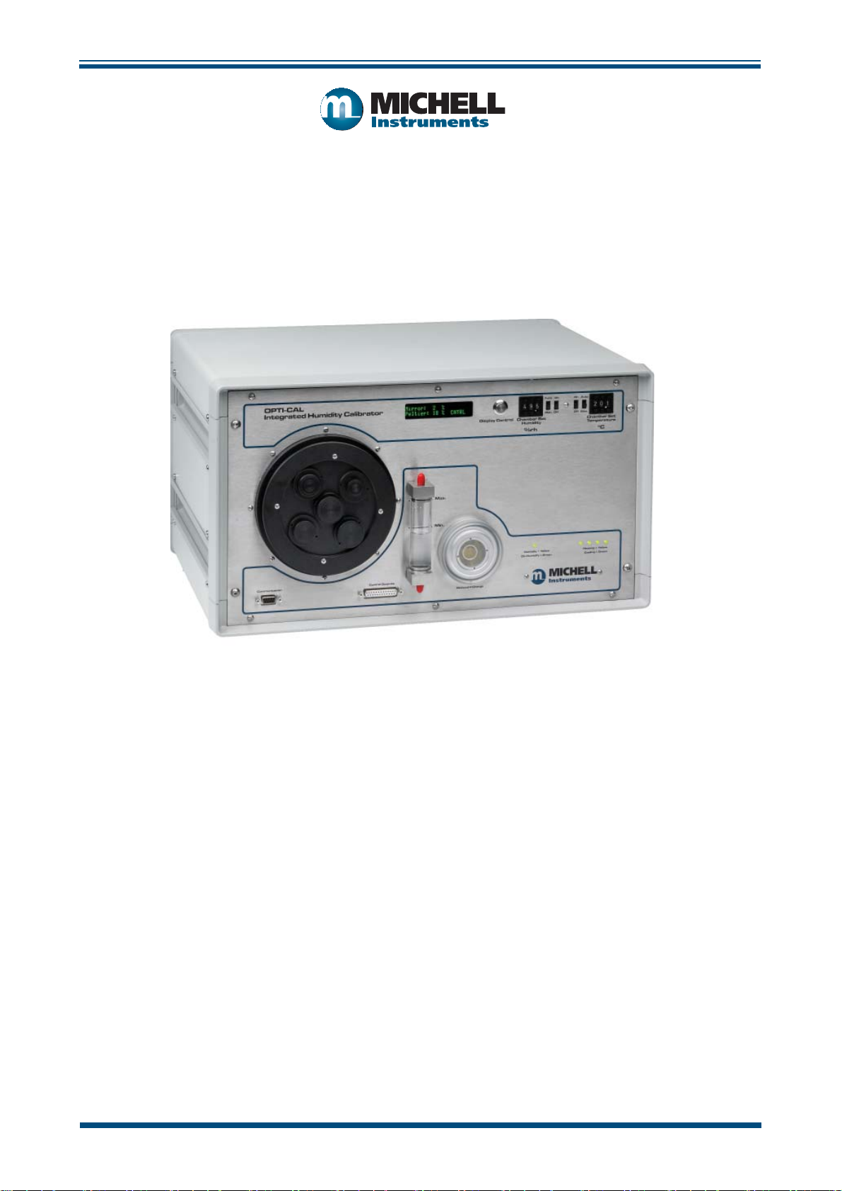
Figure 1 OptiCal - Front View ...................................................................................2
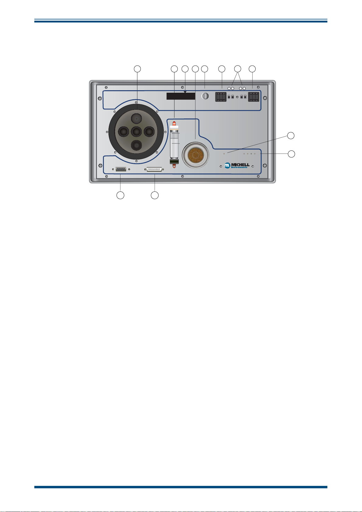
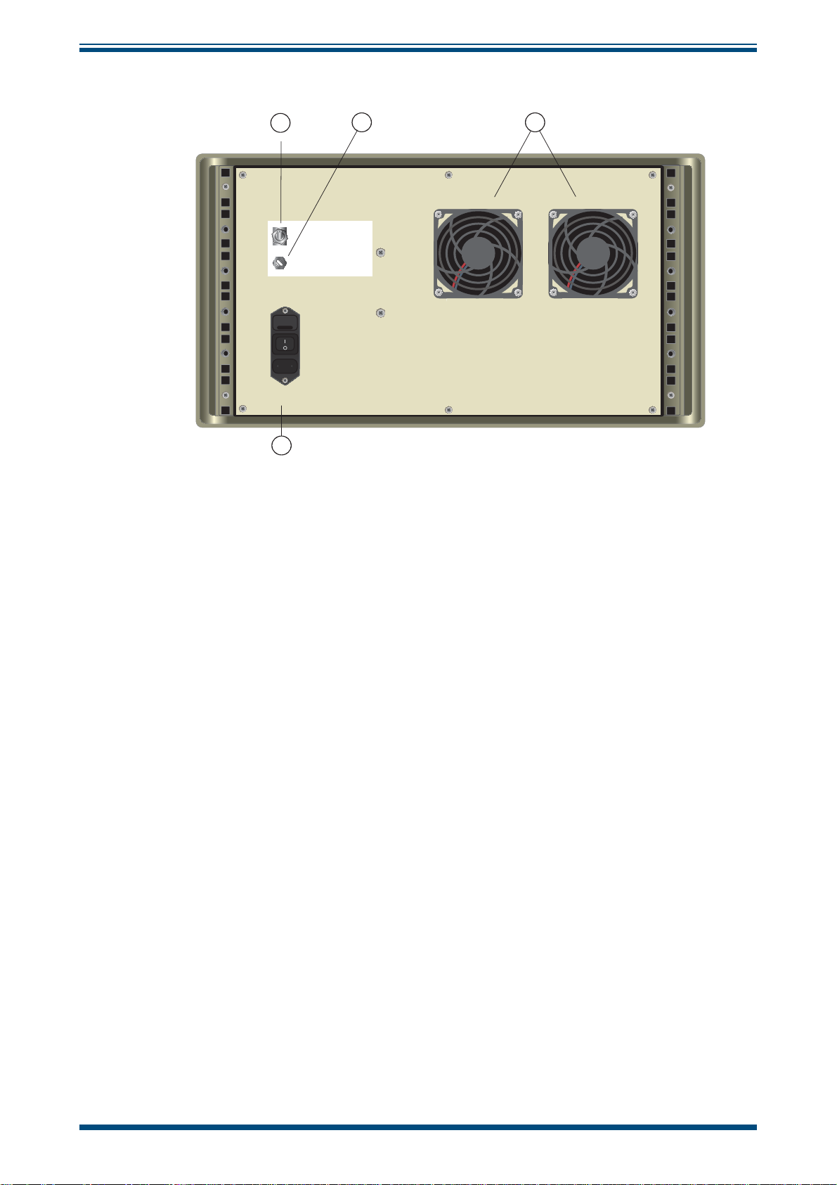
Figure 2 OptiCal - Back Panel ...................................................................................3
Figure 3 Probe Installation .......................................................................................4
Figure 4 Location of Probes Inside the Climate Chamber ............................................5
Figure 5 Filling the Water Reservoir ..........................................................................6
Figure 6 Emptying the Water Reservoir .....................................................................7
Figure 7 Desiccant Replacement ...............................................................................8
Figure 8 Level of Silica Gel Required .........................................................................8
Figure 9 Probe Ports ..............................................................................................10
Figure 10 Port Adapter Removal Tool ........................................................................10
Figure 11 Port Adapters and Removal Tool ................................................................10
Figure 12 Humidity and Temperature Setting Switches ...............................................11
Figure 13 Humidity and Temperature Setting Switches ...............................................12
Figure 14 OptiCal Manual Control .............................................................................13
Figure 15 OptiCal Programming ................................................................................13
Figure 16 Optidew Chilled Mirror Reference Display and Navigation ............................18
Figure 17 Lid Screw Locations ..................................................................................19
Figure 18 Sensor Mirror Cleaning .............................................................................. 20
Figure 19 Potentiometer Location .............................................................................21
Figure 20 Virtual Hygrometer Window ......................................................................23
Figure 21 Parameter Setup Window .......................................................................... 24
Figure 22 Chart/Log Control Panel Window ...............................................................26
Figure 23 Chart Window ..........................................................................................27
Figure 24 Basic Statistics Window .............................................................................28
Figure 25 Extracts From Calibration Certifi cates .........................................................29
Figure 26 Calibration Correction Window ................................................................... 31
Figure 27 Change Password Window ........................................................................31
Tables
Table 1 Typical Response Times for Step Changes ...................................................14
Appendices
Appendix A Technical Specifi cations ..............................................................................34
Appendix B EU Declaration of Conformity......................................................................36
Appendix C Quality, Recycling & Warranty Information ................................................... 38
C.1 Pressure Equipment Directive (PED) 97/23/EC ............................... 38
C.2 Recycling Policy .......................................................................... 38
C.3 WEEE Compliance ........................................................................ 38
C.4 RoHS2 Compliance ......................................................................39
C.5 Warranty ..................................................................................... 39
C.6 REACH Compliance ...................................................................... 40
C.7 Calibration Facilities ..................................................................... 40
C.8 Return Policy ............................................................................... 41
C.9 Manufacturing Quality .................................................................. 41
Appendix D Return Document & Decontamination Declaration ........................................ 43
Michell Instruments v
Page 6

OptiCal User’s Manual
Safety
The manufacturer has designed this equipment to be safe when operated using the procedures
detailed in this manual. The user must not use this equipment for any other purpose than that
stated. Do not apply values greater than the maximum value stated.
This manual contains operating and safety instructions, which must be followed to ensure the safe
operation and to maintain the equipment in a safe condition. The safety instructions are either
warnings or cautions issued to protect the user and the equipment from injury or damage. Use
qualifi ed personnel and good engineering practice for all procedures in this manual.
Electrical Safety
The instrument is designed to be completely safe when used with options and accessories supplied
by the manufacturer for use with the instrument. The input power supply voltage is 85 to 264 V AC,
47/63 Hz.
Toxic Materials
The use of hazardous materials in the construction of this instrument has been minimized. During
normal operation it is not possible for the user to come into contact with any hazardous substance
which might be employed in the construction of the instrument. Care should, however, be exercised
during maintenance and the disposal of certain parts.
Repair and Maintenance
The instrument must be maintained either by the manufacturer or an accredited service agent. Refer
to www.michell.com for details of Michell Instruments’ worldwide offi ces contact information.
Calibration
The OptiCal contains a high precision Optidew chilled mirror hygrometer. In order to maintain full
traceability the complete OptiCal instrument should be returned annually for a service and calibration
to the manufacturer, Michell Instruments, or one of their accredited service agents.
Safety Conformity
This product meets the essential protection requirements of the relevant EU directives. Further
details of applied standards may be found in Appendix A, Technical Specifi cations.
vi 97079 Issue 9.2, March 2016
Page 7

OptiCal User’s Manual
Abbreviations
The following abbreviations are used in this manual:
°C degrees Celsius
°F degrees Fahrenheit
AC alternating current
DC direct current
3
cubic centimeters
cm
-1
grams per kilogram
gkg
-3
grams per cubic meter
gm
Hz Hertz
in inch(es)
3
cubic inches
in
kg kilogram
lbs pounds
mA milli Ampere
max maximum
min minimum
mm millimeter
N/C normally closed
N/O normally open
% percentage
RH relative humidity
RS232 serial data transmission standard
T temperature
USB Universal Serial Bus
V Volts
Warnings
The following general warning listed below is applicable to this instrument. It is repeated
in the text in the appropriate locations.
Where this hazard warning symbol appears in the following
sections it is used to indicate areas where potentially hazardous
operations need to be carried out.
Michell Instruments vii
Page 8

OptiCal User’s Manual
1 INTRODUCTION
1.1 Description
The Michell OptiCal is a stable and accurate calibration solution for humidity sensors
over the 10 to 90%RH and +10 to +50°C (+50 to +122°F) range. The stand-alone,
transportable calibrator requires no external services other than mains power, and
features an integrated chilled mirror reference instrument to enable the operator to
perform calibrations that are traceable to national standards.
The calibration chamber features fi ve interchangeable ports to accommodate virtually
any brand, type or model of sensor. The environment within the insulated calibration
chamber is temperature controlled using a four-zone fan-assisted peltier arrangement
for maximum stability and minimum temperature gradient. The humidity of the
circulating air is precisely regulated using a closed-loop control system that functions
by proportionally mixing fl ows of dry and saturated air.
A bright and clear VFD (vacuum fl uorescent display) displays the parameters measured
by the reference instrument in various relative and absolute humidity units, alongside
the temperature within the chamber.
INTRODUCTION
The humidity and temperature set-points can be controlled either manually or
automatically as part of a calibration program. Manual control is achieved by the switches
on the front panel. Response time to a humidity or temperature step change is typically
quicker than ten minutes. The supplied application software allows calibration programs
to be created, enabling automatic time-based control of temperature and humidity set
points. The software also allows the user to monitor, chart and log calibration reference
data on a PC for later analysis.
The desiccant changes color to indicate when it needs to be recharged, and is visible
through a clear window on the front of the unit. Recharge the desiccant following the
instructions in Section 2.4. The water reservoir at the front of the unit shows the current
saturator fi ll level, and makes it easy to top up with distilled water when required (refer
to Section 2.2). Apart from periodic calibration of the chilled mirror reference, no other
maintenance is necessary. The only external service required is a single phase power
supply.
Michell Instruments 1
Page 9
INTRODUCTION
1.2 System Components
1.2.1 Front Panel
OPTI-CAL
integrated Humidity Calibrator
OptiCal User’s Manual
h
A A
Auto On On Auto
Man. Off Off Man.
h
B B
7
h
Chamber Set
Temperature
1 2 643 8
h
h
5
h
Display Control
495 206
Chamber Set
Humidity
%rh
h
h
°C
Max.
h
Min.
Data Acquisition Control Outputs
h
h
Desiccant Charge
Humidity = Yellow
De-Humidify - Green
h
Heating = Yellow
Cooling = Green
h
12
11
Figure 1
OptiCal - Front View
1. Chamber door
2. Water reservoir
3. Optidew chilled mirror reference VFD display
4. Desiccant cell and indicator window
5. Display control
6. Relative humidity set point (%RH)
A Manual/auto switches for relative humidity / temperature control
7.
9
10
MAN - Front panel switches control relative humidity / temperature set
points
AUTO - Remote RS232 / OptiSoft controls relative humidity / temperature
set points (see Section 3.4)
B ON/OFF switches for relative humidity / temperature control
8. Temperature set-point (°C)
9. Humidity control indication LED
Humidify (yellow)
De-humidify (green)
10. 4-Zone chamber temperature control indication LEDs
Heating (yellow)
Cooling (green)
11. Control outputs
12. RS232 digital communications connector
2 97079 Issue 9.2, March 2016
Page 10
OptiCal User’s Manual
Back Panel
INTRODUCTION
1
h
On
Off
h
h
4
Remote Communications
Optics Adjustment
Figure 2
2
3
h
h
OptiCal - Back Panel
1. Remote Communications Switch to enable remote chamber control
2. Optidew chilled mirror reference optics adjustment potentiometer (refer
to Section 4.2)
3. Ventilation fans
4. Electrical mains connector, on/off switch and power input fuse
Accessories
The OptiCal humidity and temperature generator is delivered with the following standard
accessories:
• Bottle of distilled water
• Desiccant cell fi lled with indicating silica gel
• HT961T00 control probe + temperature probe
• Chamber door (according to customer specifi cation)
• IEC mains cord set
• Calibration certifi cate for internal reference probe
• Certifi cate of conformity (graph)
• User’s manual
• RS232 cable
• Application software
• Calibration certifi cate for Optidew chilled mirror reference instrument
Michell Instruments 3
Page 11
INSTALLATION
2 INSTALLATION
Before using the OptiCal make sure that Sections 2.1, 2.2 and
The OptiCal enclosure is designed for bench top mounting in a laboratory type
environment. It must be positioned in a clean and level location with suffi cient clearance
at the rear of the enclosure for adequate ventilation.
The OptiCal is not designed to be fully portable. However, it can
easily be moved to any suitable location for use. Before moving,
ensure that any water in the reservoir is drained and that the
RH control probe and the temperature probe in the chamber are
OptiCal User’s Manual
2.4 are read thoroughly.
removed.
The OptiCal should NOT be moved while in operation.
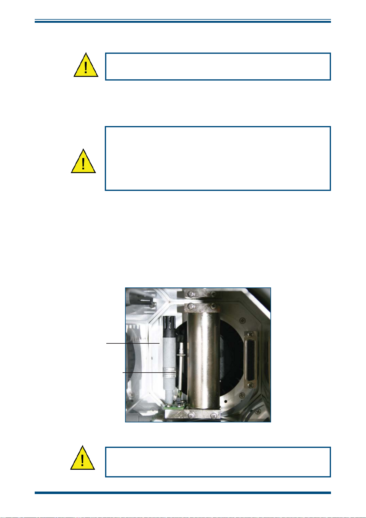
2.1 Installing the Relative Humidity and Temperature Control Probes
The relative humidity control probe and the Pt100 temperature probe are both supplied
as accessories with the OptiCal, and are removed during transportation.
To install the probes, remove the chamber door and plug in the probes as shown in
Figure 3.
This internal RH control probe is delivered with its own calibration certifi cate.
RH Control
Probe
Temperature Probe
Figure 3
The RH control probe and the temperature probe must always
Probe Installation
be removed during transportation.
4 97079 Issue 9.2, March 2016
Page 12
OptiCal User’s Manual
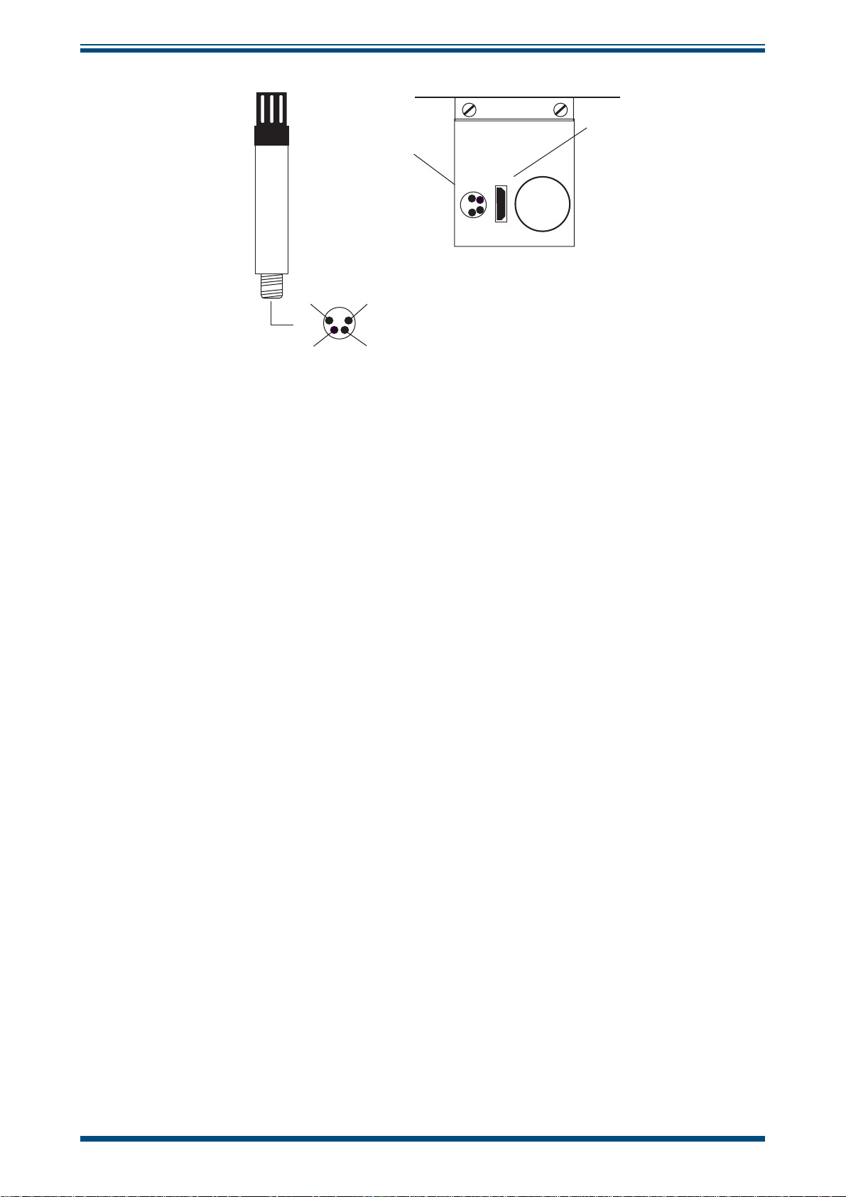
Control
Probe
Connector
INSTALLATION
Temperature
Probe
Connector
h
h
TOP VIEW
GND
OUTPUT TEMP
Figure 4
+ SUPPLY (8 - 35 VDC)
OUTPUT RH
BOTTOM VIEW
Location of Probes Inside the Climate Chamber
Michell Instruments 5
Page 13
INSTALLATION
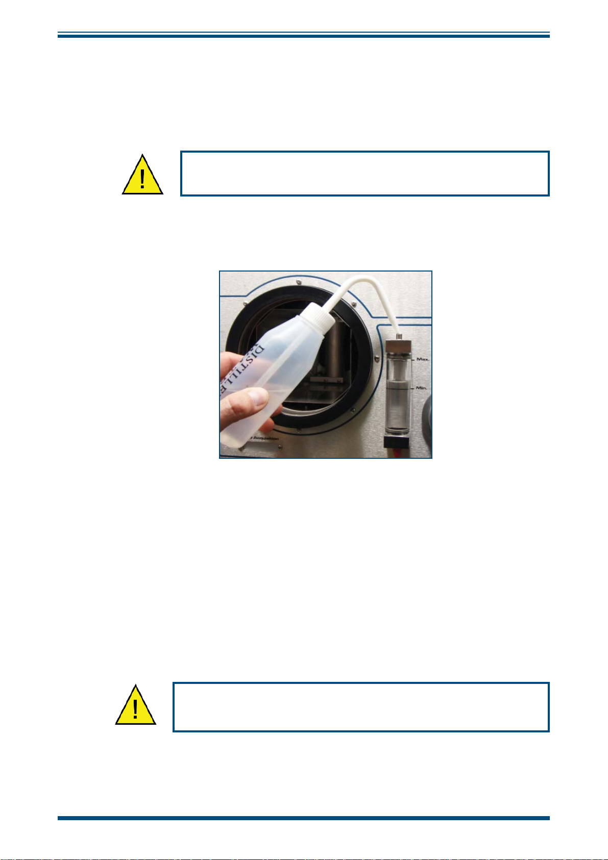
2.2 Filling the Water Reservoir
Before operation the water reservoir located on the front panel must be fi lled with
distilled water (supplied with the instrument).
Do not use tap water or demineralized water!
OptiCal User’s Manual
Figure 5
Use the fi lter bottle supplied to fi ll the water reservoir.
1. Remove the red plastic cap from the top of the reservoir.
2. Carefully fi ll with clean distilled water to a level between the two indicator
lines.
3. Replace the red cap on the water reservoir after fi lling.
Do NOT fi ll above the MAX indicated line as this may cause liquid
to enter the humidity chamber and adversely affect the control
Filling the Water Reservoir
process.
6 97079 Issue 9.2, March 2016
Page 14
OptiCal User’s Manual
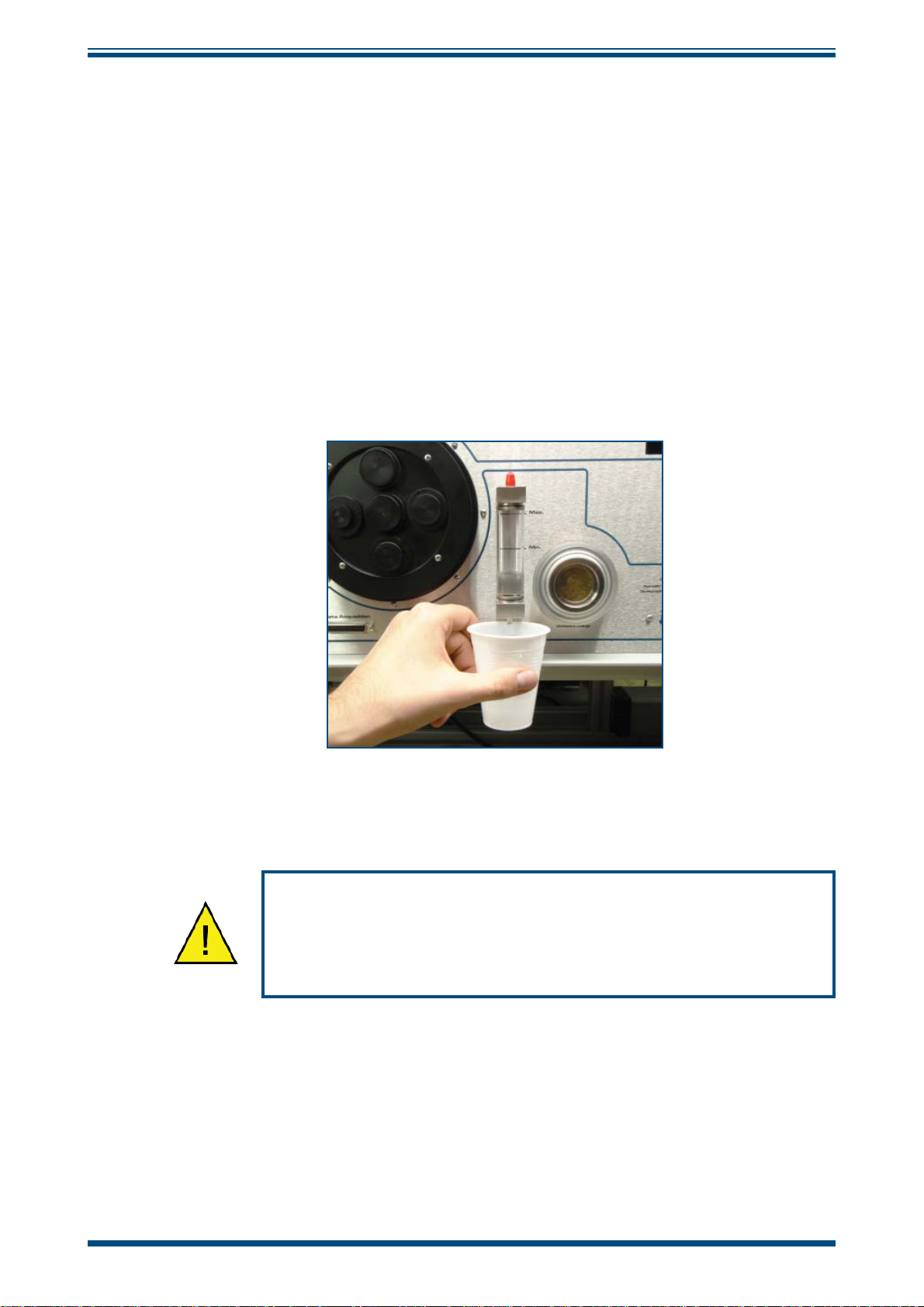
2.3 Draining the Water Reservoir
Drain the water reservoir before transporting, or if the system is accidentally overfi lled.
To empty the water reservoir:
1. Remove the red caps from the bottom and top of the water reservoir.
2. Drain the water into a suitable container.
3. Tilt the OptiCal to empty it completely.
4. Re-fi t the red cap after emptying.
INSTALLATION
Figure 6
It is essential to drain the water reservoir before transporting or
when the system is not going to be used for a few weeks.
Do not re-use any of the drained water within the system.
Emptying the Water Reservoir
Michell Instruments 7
Page 15
INSTALLATION
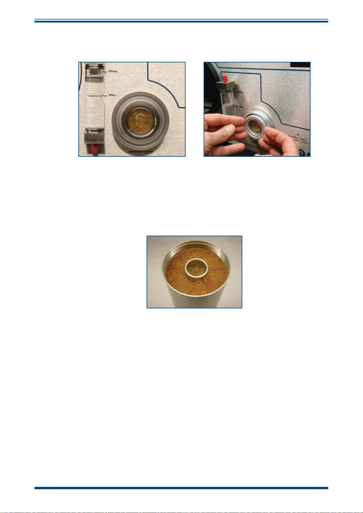
2.4 Desiccant
The OptiCal has a container fi lled with a desiccant which is used to dry the chamber air.
The desiccant container can be accessed by following these steps:
Figure 7
OptiCal User’s Manual
Desiccant Replacement
1. Remove the clear plastic screw cap on the front panel.
2. Pull out the desiccant container using fi nger tips.
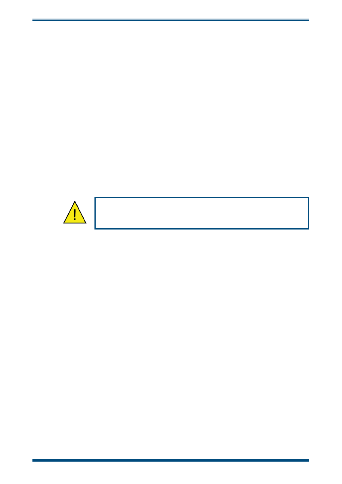
3. Fill with desiccant up to the tapered thread as shown below.
Figure 8
The natural color of the desiccant (dry silica gel) should be orange. As moisture is
absorbed the color will gradually change to transparent.
When the desiccant has become transparent, this is an indication that the instrument’s
ability to generate low humidity is reduced. It is recommended that the silica gel is
replaced or regenerated at this time.
The silica gel can be regenerated by emptying it completely from the desiccant chamber
and drying it in an oven for approximately 3 hours at a temperature between 130°C
(266°F) and 160°C (320°F). After drying it in an oven, allow the silica gel to cool before
refi lling the desiccant chamber and refi tting the chamber into the generator. Ensure that
the screw lid is correctly fi tted.
Level of Silica Gel Required
Frequency of desiccant regeneration or replacement is dependant entirely upon the
length of time in operation. Typically, given a normal calibration profi le and operation
cycle, the OptiCal can continually generate accurate and stable chamber humidity for a
period of several weeks before regeneration or replacement of the silica gel is necessary.
8 97079 Issue 9.2, March 2016
Page 16
OptiCal User’s Manual
2.5 Power Supply
A single mains power supply between 85 to 264 V AC is required to operate the unit.
The power supply connection is a 3 pin IEC plug located on the rear panel of the
instrument. The
adjacent to the power socket.
A 3-core power cable is provided, the free end of which should be wired to a suitable
earthed plug or directly connected via a fused power spur. The power cable conductors
are color coded according to the international convention:
Brown L (Live)
Blue N (Neutral)
Green/Yellow E (Earth/GND)
ON/OFF switch and the power input fuse are in the same location,
INSTALLATION
The instrument must be connected to an electrical earth for
safety purposes.
Michell Instruments 9
Page 17

OPERATION
OptiCal User’s Manual
3 OPERATION
3.1 Preparation
3.1.1 Installing Relative Humidity Instruments for Calibration
Relative humidity probes can easily be installed into the humidity chamber through
the ports in the door. The amount and size of the ports are supplied per customer
specifi cation.
h
h
Port openings
available per
customer specification
Figure 9
NOTE: Ports which are not being used should be covered with a blind stop
to exclude temperature and relative humidity infl uences from outside the
chamber.
NOTE: If a door without ports (A000268) is used, the probes under calibration
must be placed inside the measurement chamber. To ensure good air fl ow, do
not overfi ll the chamber with probes.
The ports adapters can be changed using a port adapter removal tool (A000265)
available from Michell Instruments.
Probe Ports
Blind stop
Figure 10
Insert the two pegs on the adapter tool into the corresponding holes on the port
adapters and turn counter-clockwise to loosen, and clockwise to tighten.
Figure 11
Port Adapter Removal Tool
Port Adapters and Removal Tool
10 97079 Issue 9.2, March 2016
Page 18

OptiCal User’s Manual
OPERATION
3.2 Start-Up
After installing the calibration instruments, switch on the OptiCal by using the ON/OFF
switch on the rear panel of the instrument.
3.3 Local Control of Chamber Temperature and Humidity Set Points
The desired percentage of relative humidity and temperature (in °C) can be manually
set by using the humidity and temperature setting switches when the
switches are in the
disabled individually using the associated
NOTE: Suffi cient time must be allowed for the OptiCal to thermally stabilize
before monitoring the humidity and temperature readings.
MAN position. Humidity or temperature control can be enabled or
ON/OFF switch.
AUTO/MAN
Auto On On Auto
450
Chamber Set
Humidity
Figure 12
Man. Off Off Man.
Humidity and Temperature Setting Switches
245
Chamber Set
Temperature
1. Put the AUTO/MAN switches into the MAN position.
2. Put the
3. Set the
to the
ON/OFF switches into the ON position.
REMOTE COMMUNICATION switch on the back of the instrument
OFF position.
Michell Instruments 11
Page 19

OPERATION
OptiCal User’s Manual
3.4 Remote Control of Chamber Temperature and Humidity Set Points
To enable remote control of temperature and humidity set points follow the instructions
below:
Auto On On Auto
245
Chamber Set
Temperature
Display Control
450
Chamber Set
Humidity
Man. Off Off Man.
Figure 13
1. Put the AUTO/MAN switches into the AUTO position.
2. Put the
ON/OFF switches into the ON position.
3. Set the REMOTE COMMUNICATION switch on the back of the instrument
to the
ON position.
4. Put the Optidew in
5. The OptiCal temperature and humidity set points can now be controlled
from the OptiCal application software. Refer to Section 3.4.3 and Section
3.4.4.
NOTE: If the OptiCal is used with manual set-points, put the switches into
the MAN position (refer to Section 3.3).
3.4.1 Digital Communications
Humidity and Temperature Setting Switches
REMOTE Mode. Refer to Section 4.1.
Located on the front panel is a 9 way ‘D’ connector, which is used to communicate with
Opti-Soft application software or with an ASCII terminal program (see Section 5).
The communication interface is RS232.
Pin number RS232
2Tx
3Rx
5 GND
NOTE: To enable remote control of the chamber set points, both the front
panel
AUTO/MAN switches should be set to AUTO and the rear panel REMOTE
COMMUNICATIONS switch set to ON. The Optidew should also be in REMOTE
Mode. Refer to Section 3.4.2 and Section 4.1.
12 97079 Issue 9.2, March 2016
Page 20

OptiCal User’s Manual
3.4.2 Putting the Optidew in Remote Mode
On start-up, the Optidew reference is automatically in LOCAL Mode. Once the display
has stopped showing the start-up banner it is possible to change between the two modes
by simply holding down the DISPLAY CONTROL button for approximately 7 seconds. In
REMOTE Mode the display will show REMOTE MODE, indicating that communication
with a PC via the RS232 port is possible.
3.4.3 Remote Control - Manual Set Point Control
Opti-Soft has the facility to manually control the OptiCal via the manual control window.
To set the required %RH and temperature values, adjust the controls and press the
Apply button.
OPERATION
Figure 14
3.4.4 Remote Control - Automatic Set Point Control
Opti-Soft provides a programming facility for the OptiCal, where the user can design,
open and save programs with up to 10 dwell-points.
Figure 15
OptiCal Manual Control
OptiCal Programming
Program progress is shown by the color change in the program table and the dwell time
of the active dwell point is decremented every second to show the time remaining.
Michell Instruments 13
Page 21

OPERATION
OptiCal User’s Manual
3.5 Typical Response Times for Various Step Changes
Typical response times for various step changes are shown in Table 1 below. T100
represents the total time taken to reach stability at the new set-point.
T63 and T95 values represent the time taken to reach 63% and 95% respectively of
the step change in relative humidity and/or temperature. (Start temperature = 23°C /
Start RH = 50%)
Temperature °C RH % T63 T95 T100
Step 1 15 20 ≤12 ≤23 ≤26
Step 2 15 50 ≤2 ≤3 ≤5
Step 3 15 80 ≤3 ≤7 ≤9
Step 4 25 20 ≤3 ≤5 ≤14
Step 5 25 80 ≤3 ≤8 ≤10
The time taken depends on the quality of the desiccant and the overall temperature of the OptiCal calibration chamber
•
Time in minutes
Table 1 Typical Response Times for Step Changes
The OptiCal can also be used with relative humidity generation only or with temperature
generation only.
For example: If the calibration on the instruments is done and new instruments need
to be inserted, both switches can be set to
OFF. This will cause the pump to switch off
in order to save energy.
If only temperature calibration is needed, humidity generation can be switched off.
NOTE: In this instance, the pumps will also stop.
The minimum chamber temperature that can be reached is about 10°C (18°F) below
ambient temperature. The maximum chamber temperature is limited to about +52°C
(+125°F).
14 97079 Issue 9.2, March 2016
Page 22

OptiCal User’s Manual
3.6 Control Outputs
Pin Number Description
1 4-20 mA temperature output (chilled mirror)
20 V
3 4-20 mA %RH output (chilled mirror)
40 V
5 N/C
6 0-10 V temperature output (control probe)
70 V
8 0-10 V %RH output (control probe)
9 Chilled mirror, clean optics / alarm relay N/O
10 Chilled mirror, clean optics / alarm relay COM
11 Chilled mirror, clean optics / alarm relay N/C
12 Chilled mirror status relay N/O
13 Chilled mirror status relay COM
14 Chilled mirror status relay N/C
OPERATION
Warning:
Maximum 100 mA per channel
Maximum relay voltage 30 V
Michell Instruments 15
Page 23

OPTIDEW
4 OPTIDEW REFERENCE INSTRUMENT
The OptiCal is supplied with an integrated Optidew chilled mirror reference instrument
to provide a fundamental and traceable reference measurement of the humidity within
the chamber, while being totally independent from the controlling relative humidity
probe. The advantage of this technique is to isolate the control of the chamber from
the control system of the chilled mirror sensor to provide a fast responding and highly
stable system.
4.1 Optidew Display
The Optidew reference has an integral VFD (Vacuum Fluorescent Display) mounted on
the front panel of the OptiCal instrument. To the right of the display is a single multifunction button which enables the user to select between the Optidew’s two modes of
operation and scroll through the measured and calculated parameters such as ambient
temperature or relative humidity, and indications of system status. The mode can be
either LOCAL or REMOTE. In LOCAL Mode the integral display is active and data such
as temperature and relative humidity are displayed on the VFD screen. In
Mode the display is inactive and the RS232 output is enabled and available via the 9 pin
RS232 communication connector.
OptiCal User’s Manual
REMOTE
Start-up banner
When power is applied to the OptiCal, the Optidew reference display will initially show
test characters for approximately 0.5 seconds, after which the start-up banner will be
displayed for approximately 7 seconds. The instrument will start up in
which case the display is active and the RS232 output is not available.
Remote Mode for communication with a PC
On start-up, the Optidew reference is automatically in
has stopped showing the start-up banner it is possible to change between the two modes
by simply holding down the
REMOTE Mode the display will show REMOTE MODE, indicating that communication
In
with a PC via the RS232 port is possible.
LOCAL Mode
rh 49.9 %
t 10.0 °C
REMOTE Mode
DISPLAY CONTROL button for approximately 7 seconds.
* REMOTE MODE *
LOCAL Mode. Once the display
LOCAL Mode in
4.1.1 Selecting Which ‘Screen’ to View on the Display
After the start-up banner has ended, the display will show Screen 1. This displays
the status of the Optidew chilled mirror reference instrument, i.e. DCC and ambient
temperature. To scroll to Screen 2 - fi rmly but momentarily press the multifunction
button. It is not possible to view any other screens until the
complete. Note that there may be a small delay before the display changes to the next
screen - this is normal. After the
All eight screens can now be accessed by depressing the multi-function button.
DATA HOLD period has fi nished, Screen 3 will appear.
DATA HOLD period is
16 97079 Issue 9.2, March 2016
Page 24

OptiCal User’s Manual
4.1.2 Description of Screens 1- 8
Below is a description of the parameters and system status information shown on each
screen (see
Screen 1: Displays the status of the Optidew chilled mirror reference instrument
Figure 16).
OPTIDEW
It will show
DCC, DATA HOLD, OPTICS ALARM or MEASURE according to the current
status of the Optidew chilled mirror reference instrument.
Screen 2: Peltier power and the Mirror condition
Peltier power indicates how much the heat pump is depressing in order to measure
the dew point. When the peltier power has a value of 100% and does not reduce over
an extended period of time, it means that the heat pump is at maximum depression.
In normal operation this indicates that the dew point is lower than the present mirror
temperature and therefore cannot be measured.
Alongside the peltier power value is an indicator that shows the control stability. When
this indicator shows
on the dew point.
form dew on the mirror surface.
CNTRL, it indicates the system is controlling the mirror temperature
COOL indicates the system is depressing the heat pump in order to
HEAT indicates a rapid increase in dew-point level,
whereby the system needs to increase the temperature of the mirror surface to read
this new dew-point value.
The mirror condition indicates the amount of signal received back from the mirror which
includes both the level of moisture and contamination on the mirror surface. In
DCC
mode this display will only show the amount of mirror contamination and, if greater
than 80% after a
DCC, will initiate an optics alarm condition.
Screen 3: Humidity in %RH and ambient temperature
Screen 4: Humidity in dew-point and ambient temperature
Screen 5: Humidity in gkg
Screen 6: Humidity in gm
Screen 7: The fi rst line in this screen displays Δ (t – t
-1
and ambient temperature
-3
and ambient temperature
). This is the difference between
dp
ambient temperature and dew point. Note that this parameter will be equal to 0 if
the dew point is higher than the ambient temperature (e.g. during a
DCC cycle). The
second line displays the ambient temperature.
Screen 8: The fi rst line displays a
which is equivalent to %RH/100. The second line
W
displays ambient temperature.
Michell Instruments 17
Page 25

OPTIDEW
OptiCal User’s Manual
Apply
Power
h h h h h h h h h
h
h
During DCC, Hold
and Optics Alarm
Optidew Transmitter
Initialising
Status = MEASURE
Mirror: 50%
Peltier: 40% COOL
rh 49.9 %
t 10.0 °C
tdp 0.0 °C
t 10.0 °C
Start up
banner
Screen 1
Screen 2
Screen 3
Screen 4
Y 106.00 gkg-1
t 10.0 °C
dv 106.00 gm-3
t 10.0 °C
(t-tdp) 10.0 °C
t 10.0 °C
aw 0.5
t 10.0 °C
Screen 5
Screen 6
Screen 7
Screen 8
Figure 16
Optidew Chilled Mirror Reference Display and Navigation
18 97079 Issue 9.2, March 2016
Page 26

OptiCal User’s Manual
!
4.2 Maintenance
Failure to follow these maintenance procedures may result in
premature wear or damage to the heat pump.
4.2.1 Removing the Chilled Mirror Reference Sensor for Mirror Cleaning
1. Remove the 4 screws securing the top lid to the OptiCal.
Screws
OPTIDEW
Figure 17
2. Disconnect the sensor cable from the Optidew sensor.
3. Unscrew the Optidew sensor from the side of the chamber.
Lid Screw Locations
4. Clean the sensor mirror according to the instructions in the next section.
Michell Instruments 19
Page 27

OPTIDEW
4.2.2 Sensor Mirror Cleaning
Throughout the life of the instrument, periodic cleaning of the mirror surface and optics
window may be required. Sensor cleaning is mandatory if the instrument indicates an
optics fault.
The cleaning procedure is as follows:
1. Switch off the instrument and remove the sensor from its sample block.
2. Clean the mirror surface and optics window with a cotton bud/Q-Tip
soaked in distilled water. If the sensor has been exposed to oil based
contamination then use one of the following solvents: methanol, ethanol,
or isopropyl alcohol. To avoid damage to the mirror surface do not press
too fi rmly on the cotton bud/Q-Tip when cleaning. Allow the cleaning
solvent to fully evaporate.
3. Reset the mirror condition according to the instructions in Section 5.2.
OptiCal User’s Manual
Figure 18
Sensor Mirror Cleaning
20 97079 Issue 9.2, March 2016
Page 28

OptiCal User’s Manual
4.2.3 Resetting the Mirror Condition
This is an important part of the normal operation of the instrument. The mirror condition
should be reset:
• after the mirror has been cleaned.
OPTIDEW
• if the mirror condition shows
LOW or fl ashing 0% on the display or
application software during a DCC cycle.
• if the mirror condition is greater than 10% during a DCC cycle.
Potentiometer
On
Remote Communications
Off
h
Optics Adjustment
Figure 19
Potentiometer Location
Procedure (using display or application software)
NOTE: The instructions on the next page can be followed for adjustment using
RS232 serial commands, if more convenient.
1. Clean the mirror according to the instructions above.
2. Cycle power to the instrument to initiate a DCC cycle.
The instrument will now be in DCC for 4 minutes – it is important that the
adjustments are only made in this mode. If the instrument comes out of
DCC (the status LED will no longer be illuminated), just cycle power to the
instrument.
3. Observe the mirror condition on the display, or the application software.
4. Adjust the potentiometer until the mirror condition is 0 - 2%.
If the mirror condition shows
LOW (on the display) or fl ashing 0% (on the
application software) then it is under-range and a positive adjustment is
required.
NOTE: During adjustment there will be a delay of approximately
5 seconds before the mirror condition value updates to the actual
value.
5. Cycle power to the instrument.
Michell Instruments 21
Page 29

OPTIDEW
Procedure (using RS232 serial commands)
1. Connect to the instrument using the RS232 connection.
2. Send the following commands, one after the other:
OptiCal User’s Manual
Command Description
st Stops all continuous output to the serial port
gofth
abc Starts a DCC cycle
The instrument will now be in DCC for 4 minutes – it is important that
the adjustments are only made in this mode. During this time adjust the
potentiometer until the signal level is 150 ±10.
If the instrument comes out of DCC (the status LED will no longer be
illuminated) send the
Continuously outputs signal mirror level, between 0 and
1023
abc command again.
3. Once adjustment is complete, cycle power to the instrument.
4.2.4 Re-calibration of the Chilled Mirror Reference
As with all high quality measuring instruments, regular re-calibrations of the integral
chilled mirror reference against a standard is recommended. This can only be achieved
by exposure of the sensor to sample gases of known moisture content, while comparing
readings against a calibrated reference instrument traceable to national standards. It
is recommended that the entire instrument is returned to Michell Instruments on an
annual basis for calibration and routine maintenance and service.
The accuracy and integrity of the Optidew reference will highlight any drift in the
accuracy of the controlling %RH probe, which will be seen as a difference between
the set point for %RH and temperature and the values measured by the reference
instrument. When these differences become signifi cant, then a replacement %RH probe
will be required.
22 97079 Issue 9.2, March 2016
Page 30

OptiCal User’s Manual
5 APPLICATION SOFTWARE
The application software is an interface to the OptiCal. It provides a display of the
measured and calculated parameters, system status, charting and logging, statistical
information and a facility to view and change the system parameters. To set up the
Digital Communications refer to Section 3.4.1.
NOTE: Communication with the software is only possible when the unit is in
REMOTE Mode (see Section 4.1).
5.1 Virtual Hygrometer
The Virtual Hygrometer window provides a display for the instrument by showing the
measured parameters and status.
APPLICATION SOFTWARE
Figure 20
The Humidity display has the ability to show dew point (°C/°F), %RH, gm-3, gkg-1, ∆
(t – t
will show the measured or calculated value, but will not change the Channel 1 mA
output of the instrument, as this can only be done via the Parameter Setup window
(see Section 5.3). When the software is executed, it will default to the present setting
of Channel 1 mA output. The ambient temperature is constantly shown in the lower
display. NOTE: The
the temperature, e.g. during DCC. This is normal and not a fault.
) or aW by clicking on the Change Units button. Selecting one of these options
dp
humidity display will blink if the dew point is higher than
Virtual Hygrometer Window
Mirror Condition indicates the amount of signal received back from the mirror, which
includes both the level of moisture and contamination on the mirror surface. In
mode this display will only show the amount of mirror contamination and, if greater
than 80% after a
Instrument status is shown via the fi ve colored indicators. In
or by the
showing the
ends, the
system enters the measurement phase. The
if cleaning of the mirror surface is required. Refer to Section 4.2 for details of mirror
cleaning.
DCC Initiate button), both the DCC and Hold indicators will illuminate
DCC indicator will turn off leaving only the Hold indicator illuminated until the
DCC, an optics alarm condition will initiate.
DCC (initiated automatically
DCC status and the hold on Channel 1 mA output. When the DCC period
Fault indicator will illuminate after a DCC
DCC
Michell Instruments 23
Page 31

APPLICATION SOFTWARE
The Alarm indicator will illuminate when the measured variable exceeds the alarm set
point (if selected) (refer to Section 5.3).
Max Cool can be initiated by the Max Cool On button. Once initiated, the Max
Cool indicator will illuminate and the system will drive the heat pump into maximum
depression. This feature can be used to ascertain if the measured dew point is within
the measurement capability of the instrument.
OptiCal User’s Manual
Clicking on the
measured parameters to be viewed. See Section 5.5.
Charting and logging of the measured values can be initiated by clicking on the
Statistics button allows maximum, minimum and average values of the
log button. See Section 5.4.
Hold display in DCC mode check box stops the system from updating the display
The
during
until both
DCC, when enabled. The display is held when DCC is initiated and is not updated
DCC and Hold periods have expired.
5.2 OptiCal Remote Chamber Control
The OptiCal chamber relative humidity and temperature set points can be controlled
remotely from within OptiSoft. Refer to Section 3.4.
5.3 Parameter Setup
The Parameter Setup window allows the setting and ranging of Channel 1 and 2 mA
outputs, the duration for
pressure and alarm set points.
DCC, Measurement and Hold, and the values for atmospheric
Chart/
Figure 21
Parameter Setup Window
24 97079 Issue 9.2, March 2016
Page 32

OptiCal User’s Manual
The Display Units and Channel 1 mA output are selected by clicking the left hand mouse
button in the relevant box. This will change the settings of both the instrument and the
virtual hygrometer window. Changing the mA outputs from 4-20 mA to 0-20 mA & vice
versa will change both Channel 1 & Channel 2 mA outputs.
The maximum and minimum values of Channel 1 and Channel 2 are –200 to +1000
respectively, therefore allowing the range of the outputs to be anywhere between these
limits. The values for Max and Min must be integer values with a difference between
them of at least 1°C/F.
If Channel 1 is to be set for %RH, gm
of Channel 1 Min should be 0, as a negative value for these parameters is not possible.
The pressure value is used to correct gm-3 and gkg-1 for atmospheric pressure. By
entering the atmospheric pressure the display and Channel 1 mA output (if either gm-3
or gkg-1 is selected) will both be corrected accordingly.
APPLICATION SOFTWARE
-3
, gkg-1, or ∆ (t – tdp), then the minimum value
The Alarm can be set to
dew point, ambient temperature, temperature difference, %RH, gm-3 or gkg-1 as shown
above. The set point needs to be an integer value between –200 and +1000, although
negative set points are only valid for dew point and ambient temperature. If the process
variable exceeds the set point, the
illuminate and the Optics Fault/Alarm relay will change state.
To change any of the values, enter the required value and click on the return key. The
background of the text box will change to yellow to indicate that the change is taking
place. When confi rmation has been received that the instrument has accepted the
change, the background will change back to green.
NOTE: When the
Parameter Setup window is open, the values in the Virtual
OFF or set to be active on any of the process variables i.e.
Alarm indicator on the virtual hygrometer will
Hygrometer window are frozen. The Parameter Setup window needs to be
closed for the software to resume normal display mode.
Michell Instruments 25
Page 33

APPLICATION SOFTWARE
5.4 Charting and Logging
Clicking on the Chart/log button in the Virtual Hygrometer window brings up the
Chart / log control panel
OptiCal User’s Manual
window.
Figure 22
The chart, in its default confi guration, displays dew point, temperature and %RH.
However, gm-3, gkg-1 and ∆(t – tdp), can be added by clicking in the appropriate check
box.
Within the
minimum of 5 seconds to a maximum of 1 hour. It offers the facility to log the temperature
of the mirror while in
and chart the held data values accordingly.
To log the measured and calculated humidity values to a data fi le for further analysis,
click on the check box in the
Global section, you can select the charting and logging interval from a
DCC and Hold, or hold the measured value while in these modes
Chart/Log Control Panel Window
Logging section and specify a fi le name by clicking on the
Browse button. If a log fi le is not required simply uncheck the box.
Run, Pause and Stop the charting and logging facility, use the chart control buttons
To
accordingly.
26 97079 Issue 9.2, March 2016
Page 34

OptiCal User’s Manual
Clicking on the Run button will bring up the chart as shown below. The chart shows
the measured and calculated humidity values selected in the Chart section, with an
assigned identifi able color for each value. It is possible to scale, zoom and scroll both X
and Y axis of the chart by using the controls in the
be activated by clicking on the
APPLICATION SOFTWARE
Chart Settings window, which can
Chart Settings button.
Figure 23
The X & Y axes can be individually scaled. The X-axis can be scaled by using the ZoomX
feature in the
and max values, or selecting a parameter in the
to the actual values of the parameter.
There are a number of modes associated with the chart, which can be selected from
Chart mode list; Plot, Scroll (X, Y, & XY), Cursor, Zoom (X, Y, & XY) and Zoom Box.
the
In order to use the scrolling and zooming modes, make your selection and click the left
mouse button on the chart itself, moving the mouse across the chart accordingly with
the left mouse button held down. This will zoom or scroll the chart accordingly.
Individual data points can be selected from the chart by using the cursor mode. Select
the parameter in question by clicking on a legend on the right hand side of the chart (°C
dew point is shown as selected above) and moving the cursor to the point of interest the actual value with its time stamp will be displayed above the chart.
Chart mode section, while the Y-axis can be scaled by changing the min
Chart Window
Auto-scale list, which scales the Y-axis
Michell Instruments 27
Page 35

APPLICATION SOFTWARE
5.5 Statistics
Clicking on the Statistics button on the Virtual Hygrometer window will display the
Basic statistics window as shown below:
OptiCal User’s Manual
This window shows the maximum, minimum and average of each parameter since the
program began taking readings from the instrument, or since the re-set button was
pressed.
5.6 Control Parameters
The control parameters (protected by a password) should only
be amended by trained personnel in order to adjust the system
Contact a Michell Technical Representative for details.
Figure 24
for operation in extreme conditions.
Basic Statistics Window
(www.michell.com)
28 97079 Issue 9.2, March 2016
Page 36

OptiCal User’s Manual
5.7 Calibration Correction
The OptiCal will be delivered with a Calibration certifi cate for the Optidew chilled mirror
reference instrument detailing the deviation at each measurement point from a known
reference value. Data provided on the Calibration certifi cate is normally arranged as
shown in the following extracts:
Extract from a UKAS Calibration Certifi cate:
APPLICATION SOFTWARE
Generated
Dew point
°C
-39.89 -40.11 -20 +0.22 ±0.26
-20.10 -20.31 0 +0.21 ±0.22
0.39 0.20 21 +0.19 ±0.18
Extract from a Standard Calibration Certifi cate:
Dew-point
Temperature
°C
Generated
Dew point
-40.1 -40.2
-20.1 -20.1
Temperature
°C
0.2 0.1
Test Hygrometer
Sensor
°C
Correction
Required
°C
Instrument
Display
°C
Uncertainty
Expanded
°C
Figure 25
From time to time the Optidew reference instrument may be calibrated by an external
calibration agency, where similar data will be provided.
Extracts From Calibration Certifi cates
Michell Instruments 29
Page 37

APPLICATION SOFTWARE
The Calibration Correction window is a utility that allows an authorized user to input
calibration information in order to effect a real-time correction of the displayed, charted
and logged data within the Opti-Soft application software.
Data for dew-point temperature and ambient temperature, both in units of °C, may be
entered for correction purposes, along with the original Calibration certifi cate reference
number and date of calibration, providing full traceability of data. Once the correction
data has been applied, by clicking on the check box, the main
window will indicate that corrected data is being displayed and will show the Calibration
certifi cate number and date. This information is also saved to the
export.
OptiCal User’s Manual
Virtual Hygrometer
Log fi le for data
Figure 26
shows the Calibration Correction window. Four sets of data may be entered:
DP Ref Dew-point data for the reference hygrometer used to
calibrate the Optidew (sometimes called the actual
dew point or the standard)
DP Reading Measured dew-point value of the Optidew under test
Temp Ref Temperature data from the reference thermometer
Temp Reading Measured temperature value of the Optidew under
test
Data can be entered for between 3 and 11 different dew-point and temperature
calibration points. If no data is inserted, no calibration correction is possible. Data
should be entered with the highest dew-point and temperature values at the top of
the page, in descending value order to the bottom. If out-of-sequence data or spurious
characters are entered, the software will raise a warning message and bad data must
be re-entered.
Calibration Certificate Number fi eld is an optional entry fi eld and is alphanumeric.
The
Any information entered into this fi eld will be displayed on the main
window when calibration correction is enabled. In addition it will be saved to the Log
fi le. Similarly, the date of calibration may be entered for display and logging when
correction is enabled.
Virtual Hygrometer
30 97079 Issue 9.2, March 2016
Page 38

OptiCal User’s Manual
Once all necessary data has been entered in the Calibration Correction window, click
on the
Apply and Close to return to the main Virtual Hygrometer display. Upon the next
update, the corrections entered will be applied to all displayed and logged data, and a
legend above the display will indicate this fact. To remove
select the check box and click on Apply, then on Close.
Use Calibration Date to Correct Measure Values check box and then click on
APPLICATION SOFTWARE
Calibration Correction, de-
Figure 26
NOTE: Enter the calibration data in descending order so the highest values
are in row 1 as shown above.
5.8 Change of Password
The initial password is Michell. This can be changed after entering the Control and
Calibration Data
following window where you can enter a new password with up to 20 alphanumeric
characters. The password is not case sensitive.
windows. Selecting the Change Password menu item will display the
Calibration Correction Window
Figure 27
Change Password Window
Michell Instruments 31
Page 39

TROUBLESHOOTING
6 TROUBLESHOOTING
Problem Possible Solution
OptiCal User’s Manual
No drying
No humidifying Water level too low
No drying and humidifying Switch 2 is off
No heating or cooling Switch 3 is off
No display Fuse on back panel
No external control
Rear panel Remote Communication switch set to ON
Water in chamber; dry the chamber
Front panel switches set to AUTO
Change desiccant
32 97079 Issue 9.2, March 2016
Page 40

OptiCal User’s Manual
APPENDIX A
Appendix A
Technical Specifi cations
Michell Instruments 33
Page 41

APPENDIX A
Appendix A Technical Specifi cations
Humidity
Generated Range 10 - 90%RH
Control Element Accuracy
Stability ±0.2%RH (20 - 80%RH)
Temperature
≤ ±1%RH (10 - 70%RH)
≤ ±1.5%RH (70 - 90%RH)
OptiCal User’s Manual
Generated Range
+10 to +50°C (+50 to +122°F)
(lowest T set point = +10°C (+18°F) below ambient)
Accuracy ±0.1°C (±0.18°F)
Stability ±0.1°C (±0.18°F)
Chamber
Ramp Rate From
+20 to +40°C (+68 to +104°F)
+40 to +20°C (+104 to +68°F)
1.5°C/minute (2.7°F/minute)
0.7°C/minute (1.2°F/minute)
Control Element Removable relative humidity sensor
Reference
Accuracy
Measurement Units
Dew Point:
Temperature: ±0.1°C
Dew point (°C/°F), %RH, temperature (°C/°F), gm
water activity (aW)
±0.2°C
Analog: 4-20 mA or 0-20 mA over user-settable output
Accuracy: ±0.2°C (±3.6°F)
Outputs
500Ω Maximum Load Resistance
Digital: RS232 @ 9600 baud rate
Alarm: volt free contact, 30 V 100 mA max
General
-3
, gkg-1,
Probe Ports
Chamber Volume 2000cm
Up to 5 - sensor body diameters 5 - 25mm (0.2 - 0.98”)
accommodated by port adapters
3
(122.1in3 )
Chamber Dimensions 105 x 105 x 160mm (4.13 x 4.13 x 6.3”) (w x h x d)
Instrument Dimensions 520 x 290 x 420mm (20.5 x 11.4 x 16.5”) (w x h x d)
Set-point Resolution 0.1 for humidity and temperature
Displays 2 line vacuum fl uorescent display
Supply 85 to 264 V AC, 47/63 Hz, 150 VA
Weight 20kg (44lbs)
34 97079 Issue 9.2, March 2016
Page 42

OptiCal User’s Manual
APPENDIX B
Appendix B
EC Declaration of Conformity
Michell Instruments 35
Page 43

APPENDIX B
Appendix B EU Declaration of Conformity
OptiCal User’s Manual
36 97079 Issue 9.2, March 2016
Page 44

OptiCal User’s Manual
APPENDIX C
Appendix C
Quality, Recycling
& Warranty
Information
Michell Instruments 37
Page 45

APPENDIX C
OptiCal User’s Manual
Appendix C Quality, Recycling & Warranty Information
C.1 Pressure Equipment Directive (PED) 97/23/EC
The above Directive has been implemented in United Kingdom Law by the Pressure Equipment
Regulations 1999.
The Regulations require that all pressure equipment and assemblies within the scope of the Pressure
Equipment Directive must be safe when placed on the market or put into service.
Michell Instruments’ products have been assessed and, as referenced against the Classifi cation Charts
detailed in Annex II of the Directive, do not fall into the requirements for CE marking compliance
with the Pressure Equipment Directive.
Article 3, paragraph 3 states that any product containing a pressurized fl uid that does not qualify for
compliance should, nevertheless, be constructed with Sound Engineering Practice (SEP).
Michell Instruments attests here that its products have been designed, manufactured & tested to
assure safe operation, and in accordance with Sound Engineering Practices.
C.2 Recycling Policy
Michell Instruments is concerned with the protection of the environment. It is our commitment to
reduce and eliminate from our operations, wherever possible, the use of substances which may be
harmful to the environment. Similarly, we are increasingly using recyclable and/or recycled material
in our business and products wherever it is practical to do so.
To protect natural resources and to promote material reuse, please separate batteries from other
types of waste and recycle responsibly. If batteries are not properly disposed of, these substances
can cause harm to human health and the environment.
The product that you have purchased may contain recyclable and/or recycled parts and we will be
happy to provide you with information on these components if required. For further information
please see the following sections.
C.3 WEEE Compliance
Directive 2012/19/EU 4 July 2012 on Waste Electronic and Electrical Equipment (WEEE)
The Waste Electronic and Electrical Equipment (WEEE) Directive places rules upon European
manufacturers of electrical and electronic equipment. The directives’ aim is to reduce the impact
that electronic devices have on the environment.
Michell Instruments is in full compliance with the WEEE Directive and is registered with an approved
recycler (Registration No. WEE/JB0235YW) and treats the requirement of the directive and the
protection of the environment with the utmost importance. All Michell Instruments’ products are
appropriately marked indicating their requirement for recycling.
It may be required to return certain instruments for treatment at the end of their working life.
Feb 2013
38 97079 Issue 9.2, March 2016
Page 46

OptiCal User’s Manual
C.4 RoHS2 Compliance
Directive 2011/65/EU of the European Parliament and of the Council of 8 June 2011
The Restriction of Hazardous Substances (RoHS) Directive places rules upon European manufacturers
of electrical and electronic equipment. The directives’ aim is to reduce the impact that electronic
devices have on the environment.
According to the EC Directive 2002/95/EC, Michell Instruments’ products qualify as Category 9,
Control and Monitoring Equipment. Under the 2002/95/EC Directive, Category 9 products are exempt
from compliance with the Directive.
However, the careful design of all Michell Instruments’ products takes into consideration the
requirements of the Directive and, wherever possible, compliance is achieved. All future products
will be developed entirely using compliant materials. Furthermore, Michell Instruments is taking
active steps to remove non-compliant materials and components from existing products wherever
these may occur. Presently, none of the non-compliant materials are known to occur in Michell
Instruments’ products.
The new Directive 2011/65/EU (RoHS2) entered into force on 21 July 2011 and required all Member
States to transpose the provisions into their respective national laws by 2 January 2013.
APPENDIX C
Under the provisions of the RoHS2 EU Directive 2011/65/EU (Article 3, [24]) defi nes ‘Control and
Monitoring Equipment’ specifi cally as ‘monitoring and control instruments designed exclusively for
industrial or professional use’.
RoHS2 EU Directive 2011/65/EU states the closing date for compliance of any Control and Monitoring
Equipment product sold into the EU market place as 22nd July 2017.
However, the careful design policy of all Michell Instruments’ products continues to attain compliance
in the shortest practical timescales and strives to ensure that less than 0.1% of total mass per
product, of all non-compliant materials, appear within them. Michell Instruments continues to
monitor suppliers and material sources to ensure that compliance of goods provided is maintained.
January 2013
C.5 Warranty
Unless otherwise agreed, the Supplier warrants that, as from the date of delivery for a period of 12
months, the goods and all their component parts, where applicable, are free from any defects in
design, workmanship, construction or materials.
The Supplier warrants that the services undertaken shall be performed using reasonable skill and
care, and be of a quality conforming to generally accepted industry standards and practices.
Except as expressly stated, all warranties whether express or implied, by operation of law or
otherwise, are hereby excluded in relation to the goods and services to be provided by the Supplier.
All warranty services are provided on a return to base basis. Any transportation costs for the return
of a warranty claim shall reside with the Customer.
Michell Instruments 39
Page 47

APPENDIX C
C.6 REACH Compliance
Regulation (EC) No. 1907/2006
Registration, Evaluation, Authorisation and Restriction of Chemicals (REACH)
Michell Instruments is a manufacturer of moisture measurement and gas analysis instrumentation
and is a ‘downstream’ user of chemicals, as described by the EU Council Directive 76/769/EEC. The
products we supply are not raw chemical products (goods).
Under normal and reasonably foreseeable circumstances of application, the goods supplied to you
shall not contain or release any prohibited chemicals. No listed SVHC (Substances of Very High
Concern) appear within products manufactured by Michell Instruments. Therefore the 0.1% mass
per product, or total usage of 1 tonne/year, will never be exceeded. For these reasons we are neither
required by obligation for registration nor for the creation of material safety data sheets (MSDS) for
our products.
OptiCal User’s Manual
Our continued review of the SVHC Candidate List and
compliant.
Michell Instruments maintains a hazardous material register in which MSDS data sheets are collated,
and we will check that our suppliers will comply to REACH requirements for all materials and
substances we use in the processes of our manufacturing.
In the unlikely event that any chemicals of concern appear in our products in quantities greater than
0.1% of total mass per product we will immediately inform you by correspondence according to the
REACH Article 33 requirements. Our current appraisal is, however, that we do not expect or foresee
such an incidence.
January 2013
C.7 Calibration Facilities
Michell Instruments’ calibration facilities are among the most sophisticated in the world and have
been recognized for their excellence.
Traceability to the National Physical Laboratory (NPL) UK is achieved through our UKAS Accreditation
(Number 0179). This covers dew point over the range -90 to +90°C (-130 to +194°F) and also
Relative Humidity.
latest additions is to ensure we remain
Dew-point calibrations are also traceable to the National Institute for Standards & Technology (NIST)
USA over the range -75 to +20°C (-103 to +68°F).
NOTE: Standard traceable calibration certifi cates for instruments and sensors are not
issued under our UKAS accreditation. UKAS certifi cates are usually to special order and
are clearly identifi ed.
40 97079 Issue 9.2, March 2016
Page 48

OptiCal User’s Manual
C.8 Return Policy
If a Michell Instruments’ product malfunctions within the warranty period, the following procedure
must be completed:
1. Notify a Michell Instruments’ distributor, giving full details of the problem, the
model variant and the serial number of the product.
2. If the nature of the problem indicates the need for factory service then the
instrument should be returned to Michell Instruments, carriage prepaid, preferably
in the original packaging, with a full description of the fault and the customer
contact information.
3. Upon receipt, Michell Instruments will evaluate the product to determine the cause
of the malfunction. Then, one of the following courses of action will be taken:
• If the fault is covered under the terms of the warranty, the
instrument will be repaired at no cost to the owner and returned.
• If Michell Instruments determines that the fault is not covered
under the terms of the warranty, or if the warranty has expired,
an estimate for the cost of the repairs, at standard rates, will be
provided. Upon receipt of the owner’s approval to proceed, the
product will be repaired and returned.
APPENDIX C
C.9 Manufacturing Quality
Michell Instruments is registered with the British Standards Institute for Quality Assurance to:
BS EN ISO 9001: 2008
Rigorous procedures are performed at every stage of production to ensure that the materials of
construction, manufacturing, calibration and fi nal test procedures meet the requirements laid down
by our BSI approved Quality System.
Please contact Michell Instruments (www.michell.com) if the product does not arrive in perfect
working order.
Michell Instruments 41
Page 49

APPENDIX D
OptiCal User’s Manual
Appendix D
Return Document &
Decontamination Declaration
42 97079 Issue 9.2, March 2016
Page 50

OptiCal User’s Manual
Appendix D Return Document & Decontamination Declaration
'HFRQWDPLQDWLRQ&HUWL¿FDWH
IMPORTANT NOTE: Please complete this form prior to this instrument, or any components, leaving your
site and being returned to us, or, where applicable, prior to any work being carried out by a Michell
engineer at your site.
Instrument Serial Number
Warranty Repair? YES NO Original PO #
Company Name Contact Name
Address
Telephone # E-mail address
Reason for Return /Description of Fault:
APPENDIX D
Has this equipment been exposed (internally or externally) to any of the following?
Please circle (YES/NO) as applicable and provide details below
Biohazards YES NO
Biological agents YES NO
Hazardous chemicals YES NO
Radioactive substances YES NO
Other hazards YES NO
Please provide details of any hazardous materials used with this equipment as indicated above (use continuation sheet
if necessary)
Your method of cleaning/decontamination
Has the equipment been cleaned and decontaminated? YES NOT NECESSARY
Michell Instruments will not accept instruments that have been exposed to toxins, radio-activity or bio-hazardous
PDWHULDOV)RUPRVWDSSOLFDWLRQVLQYROYLQJVROYHQWVDFLGLFEDVLFÀDPPDEOH RUWR[LFJDVHVDVLPSOHSXUJHZLWKGU\
JDVGHZSRLQW&RYHUKRXUVVKRXOGEHVXI¿FLHQWWRGHFRQWDPLQDWHWKHXQLWSULRUWRUHWXUQ
Work will not be carried out on any unit that does not have a completed decontamination declaration.
Decontamination Declaration
I declare that the information above is true and complete to the best of my knowledge, and it is safe for Michell
personnel to service or repair the returned instrument.
Name (Print) Position
Signature Date
F0121, Issue 2, December 2011
Michell Instruments 43
Page 51

NOTES:
Page 52

http://www.michell.com
 Loading...