

Page 1
MDM300
Sampling System
User’s Manual
97232 Issue 1.4
October 2016
Page 2
Please fi ll out the form(s) below for each instrument that has been purchased.
Use this information when contacting Michell Instruments for service purposes.
Instrument
Code
Serial Number
Invoice Date
Location of Instrument
Tag No
Instrument
Code
Serial Number
Invoice Date
Location of Instrument
Tag No
Instrument
Code
Serial Number
Invoice Date
Location of Instrument
Tag No
Page 3
MDM300 Sampling System
For Michell Instruments' contact information please go to
www.michell.com
© 2016 Michell Instruments
This document is the property of Michell Instruments Ltd. and may not be copied or
otherwise reproduced, communicated in any way to third parties, nor stored in any Data
Processing System without the express written authorization of Michell Instruments Ltd.
Page 4

MDM300 Sampling System User’s Manual
Contents
Safety ................................................................................................................................ v
Electrical Safety ........................................................................................................... v
Pressure Safety ............................................................................................................ v
Toxic Materials ............................................................................................................. v
Repair and Maintenance ............................................................................................... v
Calibration ................................................................................................................... v
Safety Conformity ........................................................................................................ v
Abbreviations ......................................................................................................................vi
Warnings ............................................................................................................................vi
1 INTRODUCTION ................................................................................................1
2 INSTALLATION ..................................................................................................2
2.1 Safety ............................................................................................................... 2
2.2 Unpacking the Instrument ................................................................................... 2
2.3 Environmental Requirements ...............................................................................2
2.4 Preparing the Sampling System for Operation ....................................................... 3
2.5 Controls, Indicators and Connectors .....................................................................5
3 OPERATION ......................................................................................................6
3.1 Sample Gas Connection ...................................................................................... 6
3.2 Operating Procedure ........................................................................................... 6
3.3 Sampling Hints ................................................................................................... 7
4 MAINTENANCE ................................................................................................10
4.1 General Maintenance Guidelines ........................................................................ 10
4.2 Filter Element Replacement ............................................................................... 10
Figures
Figure 1 Panel-Mount Sampling System and Flight Case .............................................1
Figure 2 Gas Port Adaptors ......................................................................................3
Figure 3 MDM300 Positioning ...................................................................................3
Figure 4 MDM300 Inlet and Outlet Port Connection ....................................................4
Figure 5 Mounting Posts ...........................................................................................4
Figure 6 Port Connection Tightening .........................................................................4
Figure 7 Controls, Indicators and Connectors .............................................................5
Figure 8 Sample Line Connection to GAS IN Port .......................................................6
Figure 9 Filter Element Removal .............................................................................10
Figure 10 Glycol Absorption Cartridge Removal ..........................................................11
iv 97232 Issue 1.4, October 2016
Page 5

MDM300 Sampling System User’s Manual
Tables
Table 1 Controls, Indicators and Connectors ..............................................................5
Appendices
Appendix A Technical Specifi cations ..............................................................................13
Appendix B Quality, Recycling & Warranty Information ...................................................15
B.1 Pressure Equipment Directive (PED) 97/23/EC ...............................15
B.2 Recycling Policy ..........................................................................15
B.3 WEEE Compliance ........................................................................15
B.4 RoHS2 Compliance ......................................................................16
B.5 Warranty .....................................................................................16
B.6 REACH Compliance ......................................................................17
B.7 Calibration Facilities .....................................................................17
B.8 Return Policy ...............................................................................18
B.9 Manufacturing Quality ..................................................................18
Appendix C Return Document & Decontamination Declaration ........................................20
Michell Instruments v
Page 6
MDM300 Sampling System User’s Manual
!
Safety
The manufacturer has designed this equipment to be safe when operated using the procedures
detailed in this manual. The user must not use this equipment for any other purpose than that
stated. Do not subject the equipment to conditions outside of the specifi ed operating limits.
This manual contains operating and safety instructions, which must be followed to ensure the safe
operation and to maintain the equipment in a safe condition. The safety instructions are either
warnings or cautions issued to protect the user and the equipment from injury or damage. Use
competent personnel using good engineering practice for all procedures in this manual.
Electrical Safety
The instrument is designed to be completely safe when used with options and accessories supplied
by the manufacturer for use with the instrument.
Pressure Safety
DO NOT permit pressures greater than the safe working pressure to be applied to the instrument.
The specifi ed safe working pressure will be as follows (refer to Appendix A - T echnical Specifi cations):
Low pressure: 20 barg (290 psig)
Medium pressure: 110 barg (1595 psig)
High pressure: 340 barg (4931 psig)
WARNING
The fl owmeter should never be pressurized.
Always expand a pressurized sample to atmospheric pressure
before it enters the fl ow meter.
Toxic Materials
The use of hazardous materials in the construction of this instrument has been minimized. During
normal operation it is not possible for the user to come into contact with any hazardous substance
which might be employed in the construction of the instrument. Care should, however, be exercised
during maintenance and the disposal of certain parts.
Repair and Maintenance
The instrument must be maintained either by the manufacturer or an accredited service agent. Refer
to www.michell.com for details of Michell Instruments’ worldwide offi ces contact information
Calibration
The recommended calibration interval for the MDM300 Hygrometer is 12 months. The instrument
should be returned to the manufacturer, Michell Instruments, or one of their accredited service
agents for recalibration.
Safety Conformity
This product meets the essential protection requirements of the relevant EU directives. Further
details of applied standards may be found in the product specifi cation.
vi 97232 Issue 1.4, October 2016
Page 7
MDM300 Sampling System User’s Manual
!
Abbreviations
The following abbreviations are used in this manual:
AC alternating current
barg pressure unit (=100 kP or 0.987 atm) gauge
ºC degrees Celsius
ºF degrees Fahrenheit
Nl/min liters per minute
kg kilogram(s)
lb pound(s)
mm millimeters
“ inch(es)
psig pounds per square inch gauge
scfh standard cubic feet per hour
Warnings
The following general warning listed below is applicable to this instrument. It is repeated
in the text in the appropriate locations.
Where this hazard warning symbol appears in the following
sections, it is used to indicate areas where potentially
hazardous operations need to be carried out.
Michell Instruments vii
Page 8
MDM300 Sampling System User’s Manual
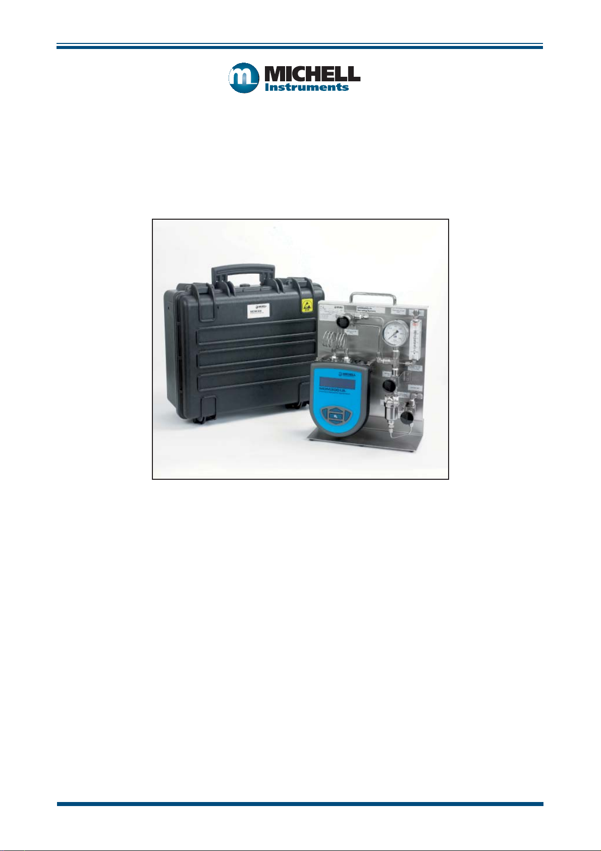
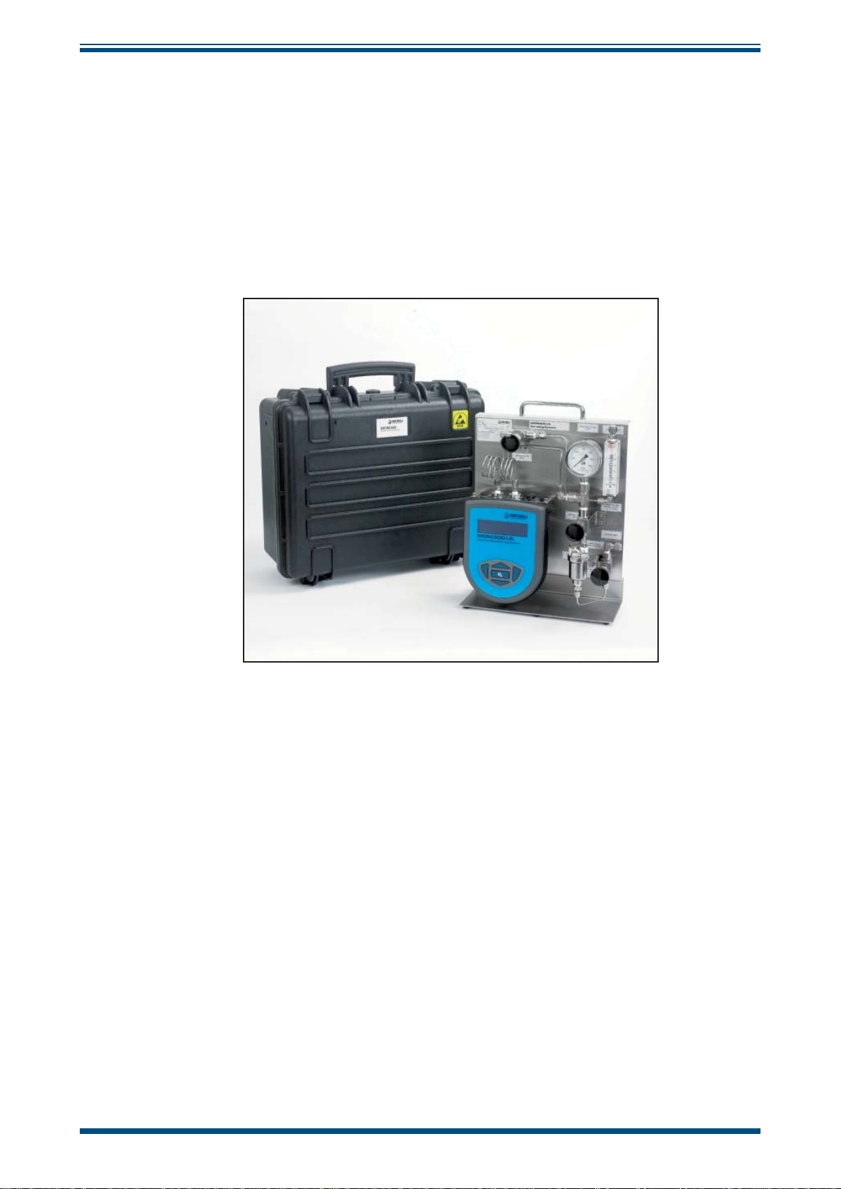
1 INTRODUCTION
The MDM300 panel-mount sampling system offers a complete package for conditioning
of a sample, prior to measurement with an MDM300 or MDM300 I.S.
It is contained within an optional fl ight case which allows easy transport of everything
required to make the measurements. The anti-static construction of the case makes it
suitable for use in hazardous areas.
INTRODUCTION
Figure 1
Panel-Mount Sampling System and Flight Case
Michell Instruments 1
Page 9

INSTALLATION
!
MDM300 Sampling System User’s Manual
2 INSTALLATION
2.1 Safety
It is essential that the installation of the electrical and
gas supplies to this instrument be undertaken by qualifi ed
2.2 Unpacking the Instrument
The shipping box will contain the following:
• MDM300 Panel-Mount Sampling System
• Flight case (optional)
personnel.
• 2.5mm Allen key
• 2 x 2.5mm hex bolts
• 2 x 1/8” NPT to 1/8” Swagelok
1. Open the box. If a fl ight case was ordered, the sampling system
will be packaged within it.
2. Remove the sampling panel (or fl ight case, if ordered) from the
box, along with the fi ttings.
3. Save all packing materials in case it is necessary to return the
instrument.
2.3 Environmental Requirements
Refer to the user’s manual for information on acceptable environmental conditions in
which to operate the MDM300.
®
adaptors
2 97232 Issue 1.4, October 2016
Page 10

MDM300 Sampling System User’s Manual
2.4 Preparing the Sampling System for Operation
To prepare the system for operation, it is necessary to install the MDM300 into the
sampling system as follows:
INSTALLATION
4. Wrap PTFE tape (not supplied), around the ends of the 1/8” NPT to 1/8”
®
Swagelok
tube fi ttings and install into the orifi ce adaptors fi tted to the
MDM300. Ensure that the orifi ce port adaptors in the MDM300 are
both large bore type (see relevant user’s manual for more details).
- I.S.
PTFE tape here
Adaptor
h
1/8” Swagelok
tting
h
h
h
Dowty seal
Large orice adaptor
Small orice
Figure 2
Gas Port Adaptors
5. Locate the MDM300 in the position shown below.
MDM300 I.S.
MDM300-IS SAMPLING
SYSTEM
Sampling System
NEEDLE VALVE
(NV2)
PRESSURE GAUGE
100
50
(PG1)
150
200
250
300
bar
2
lbf/in
NEEDLE VALVE
(NV1)
SAMPLE INLET
MAX 100 BARG
BYPASS VALVE
(NV3)
SAMPLE VENT
FLOWMETER (FM1)
OPTIMAL FLOW
0.2 - 0.5 L/MIN
BYPASS VENT
Figure 3
MDM300 Positioning
Michell Instruments 3
Page 11

INSTALLATION
6. Connect the coiled tubes to the inlet and outlet of the MDM300. Ensure
that the 1/8” Swagelok® nuts are fi nger tight.
MDM300 Sampling System User’s Manual
Figure 4
MDM300 Inlet and Outlet Port Connection
7. Secure the instrument to the mounting posts using the supplied 2.5mm
hex bolts and allen key.
;
Figure 5
- I.S.
Mounting Posts
;
8. Use a wrench/spanner to fi nish tightening the 1/8” Swagelok® nuts on the
inlet/outlet to ensure there are no leaks. The body of the 1/8” NPT to 1/8”
®
Swagelok
adaptor should be held securely with another wrench/spanner
while the nuts are tightened to prevent any movement.
- I.S.
Figure 6
Port Connection Tightening
4 97232 Issue 1.4, October 2016
Page 12

MDM300 Sampling System User’s Manual
2.5 Controls, Indicators and Connectors
INSTALLATION
MDM300-IS SAMPLING
SYSTEM
12
3
h
h
MDM300 I.S.
Sampling System
NEEDLE VALVE
(NV2)
PRESSURE GAUGE
150
100
50
bar
lbf/in
h
(PG1)
200
250
300
2
NEEDLE VALVE
(NV1)
SAMPLE VENT
FLOWMETER (FM1)
OPTIMAL FLOW
0.2 - 0.5 L/MIN
h
h
BYPASS VENT
h
- I.S.
SAMPLE INLET
MAX 100 BARG
h
h
4
5
6
7
8
Outlet
1
Metering Valve
2
Pressure Gauge
3
Sample Vent
4
Flow Meter
Inlet Metering
5
Valve
6
Bypass Port
7
Sample Inlet
Bypass
8
Metering Valve
BYPASS VALVE
(NV3)
Figure 7
Controls, Indicators and Connectors
Used to regulate sample fl ow for system pressure measurements
Should be fully open for system pressure measurements
Gauge showing the sample pressure across the sensor cell
Fitted with either a silencer or Swagelok® tube fi tting to enable
a vent line to be connected
For fl ow indication
Used to regulate sample fl ow for atmospheric pressure
measurements
Should be fully open for system pressure measurements
Outlet from the bypass path
Can optionally be connected to a vent line during operation
For connection to the sample gas line
Refer to Section 3.1 for more information on making connections
to the system
Used for regulating the fl ow rate through the bypass path
Table 1 Controls, Indicators and Connectors
Michell Instruments 5
Page 13

OPERATION
)
3 OPERATION
3.1 Sample Gas Connection
Gas is introduced to the system by connecting the sample take-off line to the GAS IN
port, as shown in
If required, connect a vent line to the BYPASS port, and to the fl owmeter vent (if fi tted).
Figure 8.
MDM300 Sampling System User’s Manual
FLOWMETER (FM1
OPTIMAL FLOW
NEEDLE VALVE
(NV1)
0.2 - 0.5 L/MIN
BYPASS VENT
Figure 8
3.2 Operating Procedure
1. Connect an instrument to the sample gas as detailed in Section 3.1.
2. Fully open the isolation valve.
3. Refer to the Operation Guide section in the relevant MDM300 user’s
manual for condition specifi c instructions on operation.
4. Depending on the sample pressure it may be necessary to use the bypass
fl ow control to overcome sample fl ow control diffi culties.
- I.S.
SAMPLE INLET
MAX 100 BARG
;
BYPASS VALVE
(NV3)
Sample Line Connection to GAS IN Port
6 97232 Issue 1.4, October 2016
Page 14

MDM300 Sampling System User’s Manual
3.3 Sampling Hints
Measurement of moisture content is a complex subject, but does not need to be diffi cult.
This section aims to explain the common mistakes made in measurement situations, the
causes of the problem, and how to avoid them. Mistakes and bad practices can cause
the measurement to vary from the expectation; therefore a good sampling technique is
crucial for accurate and reliable results.
Transpiration and Sampling Materials
- 20
- 30
OPERATION
- 40
- 50
Dew point (ºC)
- 60
- 70
12345
nickel
stainless steel
Time (hours)
nylon
copper
polyethylene
PTFE
All materials are permeable to water vapor, as the water molecule is extremely small
compared to the structure of solids, even when compared to the crystalline structure of
metals. The graph to the right shows the dew point inside tubing of different materials
when purged with very dry gas, where the exterior of the tubing is in the ambient
environment.
Many materials contain moisture as part of their structure, particularly organic materials
(natural or synthetic), salts (or anything which contains them) and anything which
has small pores. It is important to ensure that the materials used are suitable for the
application.
If the partial water vapor pressure exerted on the outside of a compressed air line is
higher than on the inside, the atmospheric water vapor will naturally push through the
porous medium causing water to migrate into the pressurized air line. This effect is
called transpiration.
Adsorption and Desorption
Adsorption is the adhesion of atoms, ions, or molecules from a gas, liquid, or dissolved
solid to the surface of a material, creating a fi lm. The rate of adsorption is increased at
higher pressures and lower temperatures.
Desorption is the release of a substance from or through the surface of a material. In
constant environmental conditions, an adsorbed substance will remain on a surface
almost indefi nitely. However, as the temperature rises, so does the likelihood of
desorption occurring.
In practical terms, as the temperature of the environment fl uctuates, water molecules
are adsorbed and desorbed from the internal surfaces of the sample tubing, causing
small fl uctuations in the measured dew point.
Michell Instruments 7
Page 15

OPERATION
Sample Tubing Length
The sample point should always be as close to the critical measurement point as possible,
in order to obtain a truly representative measurement. The length of the sample line
to the sensor or instrument should be as short as possible. Interconnection points and
valves trap moisture, so using the simplest sampling arrangement possible will reduce
the time it takes for the sample system to dry out when purged with dry gas.
Over a long tubing run, water will inevitably migrate into any line, and the effects of
adsorption and desorption will become more apparent. It is clear from the graph shown
above that the best materials to resist transpiration are stainless steel and PTFE.
Trapped Moisture
Dead volumes (areas which are not in a direct fl ow path) in sample lines, hold onto
water molecules which are slowly released into the passing gas; this results in increased
purge and response times, and wetter than expected readings. Hygroscopic materials
in fi lters, valves (e.g. rubber from pressure regulators) or any other parts of the system
can also trap moisture.
MDM300 Sampling System User’s Manual
Sample Conditioning
Sample conditioning is often necessary to avoid exposure of sensitive measuring
components to liquids and other contaminants which may cause damage or affect the
accuracy over time, depending on the measurement technology.
Particulate fi lters are used for removing dirt, rust, scale and any other solids that may
be in a sample stream. For protection against liquids, a coalescing fi lter should be used.
The membrane fi lter is a more expensive but highly effective alternative to a coalescing
fi lter. It provides protection from liquid droplets, and can even stop fl ow to the analyzer
completely when a large slug of liquid is encountered.
Condensation and Leaks
Dewpoint > T Dewpoint < T
Maintaining the temperature of the sample system tubing above the dew point of the
sample is vital to prevent condensation. Any condensation invalidates the sampling
process as it changes the water vapor content of the gas being measured. Condensed
liquid can alter the humidity elsewhere by dripping or running to other locations where
it may re-evaporate.
The integrity of all connections is also an important consideration, especially when
sampling low dew points at an elevated pressure. If a small leak occurs in a high
pressure line, gas will leak out but vortices at the leak point and a negative vapor
pressure differential will also allow water vapor to contaminate the fl ow.
8 97232 Issue 1.4, October 2016
Page 16

MDM300 Sampling System User’s Manual
!
Flow Rates
Theoretically fl ow rate has no direct effect on the measured moisture content, but in
practice it can have unanticipated effects on response speed and accur acy. The optimal
fl ow rate varies depending on the measurement technology.
MDM300 I.S. fl ow rate 0.2 to 0.5 Nl/min (0.5 to 1 scfh)
MDM300 fl ow rate 0.2 to 1.2 Nl/min (0.5 to 1.2 scfh)
WARNING
The fl owmeter should never be pressurized.
Always expand a pressurized sample to atmospheric
pressure before it enters the fl ow meter.
An inadequate fl ow rate can:
OPERATION
• Accentuate adsorption and desorption effects on the gas passing through
the sampling system.
• Allow pockets of wet gas to remain undisturbed in a complex sampling
system, which will then gradually be released into the sample fl ow.
• Increase the chance of contamination from back diffusion: ambient air
that is wetter than the sample can fl ow from the exhaust back into the
system. A longer exhaust (sometimes called a pigtail) can also help
alleviate this problem.
An excessively high fl ow rate can:
• Introduce back pressure, causing slower response times and unpredictable
effects on equipment such as humidity generators.
• Result in a reduction in heating capabilities of the sensor tile during the
initialization period. This is most apparent with gases that have a high
thermal conductivity such as hydrogen and helium.
Michell Instruments 9
Page 17

MAINTENANCE
!
MDM300 Sampling System User’s Manual
4 MAINTENANCE
4.1 General Maintenance Guidelines
Routine maintenance of the system is confi ned to fi lter element replacement and regular
recalibration of the MDM300 or MDM300 I.S. sensor. For specifi c details on replacing
fi lter elements, please see Section 4.2.
In most applications, annual recalibration ensures that the stated accuracy of the
MDM300 Advanced Dew-Point Hygrometer is maintained. The exchange sensor scheme
is the most effi cient method of providing accurate annual recalibration with minimum
downtime.
Please contact Michell Instruments for more details.
Prior to recalibration being necessary, an exchange sensor can be ordered from Michell
Instruments or any authorized dealer. Once the sensor and calibration certifi cate has
been received it can be fi tted and the original sensor returned to Michell Instruments.
For more details of recalibration of the MDM300 please see the relevant user’s manual.
4.2 Filter Element Replacement
Frequency of fi lter element replacement is primarily dependent upon the quantity of
contaminants present in the sample gas. If the gas is heavily laden with particulates or
liquids it is recommended to inspect the fi lter element on a regular basis initially, and
increase the time between inspections if the fi lter is found to be in good condition.
It is imperative that all fi lters are replaced before they become saturated. If a fi lter
element becomes saturated with contaminants there is a possibility that the performance
of the fi lter will be reduced, and contamination of the MDM300 sensor could occur.
Before attempting to replace the fi lter always disconnect the
Sampling System from the sample gas and ensure that the
To replace a particulate or coalescing fi lter element, proceed as follows:
1. Disconnect the U-shaped section of Swagelok® tubing from the fi lter drain.
system is depressurized.
BYPASS VENT
;
SAMPLE INLET
MAX 100 BARG
BYPASS VALVE
(NV3)
;
- I.S.
Figure 9
Filter Element Removal
10 97232 Issue 1.4, October 2016
Page 18

MDM300 Sampling System User’s Manual
2. Unscrew and remove the fi lter bowl and then the fi lter element. NOTE:
the fi lter bowl is sealed with an O-ring.
3. Discard the old used fi lter element and replace with a new fi lter element
Order codes:
MDM300-SAM-PAR - particulate element
MDM300-SAM-COA - coalescing element
4. Replace the fi lter bowl, ensuring the O-ring is correctly seated and
reconnect the tube to the drain port. NOTE: Tighten both securely.
To replace the glycol absorption cartridge, proceed as follows:
NEEDLE VALVE
(NV1)
h
FLOWMETER (FM1)
OPTIMAL FLOW
0.2 - 0.5 L/MIN
BYPASS VENT
MAINTENANCE
Glycol
Absorption
Cartridge
- I.S.
Figure 10
Glycol Absorption Cartridge Removal
SAMPLE INLET
MAX 100 BARG
BYPASS VALVE
(NV3)
1. Loosen union bonnet nut with open end spanner/wrench. Support
body to minimize strain on pipe or tubing.
2. Unscrew union nut and remove assembly. NOTE: Union nut,
bonnet, spring and retaining ring remain together as an
assembly.
3. Gently tap fi lter element on side to break loose from tapered
seating area.
4. Insert new glycol absorption cartridge. Tap lightly to reseat in
tapered bore.
Order code: MDM300-SAM-PNL-GLY
5. Inspect gasket and mating surfaces on bonnet and body. Clean as
required. Replacement of the gasket is recommended.
Michell Instruments 11
Page 19

APPENDIX A
MDM300 Sampling System User’s Manual
Appendix A
Technical Specifi cations
12 97232 Issue 1.4, October 2016
Page 20

MDM300 Sampling System User’s Manual
Appendix A Technical Specifi cations
Enclosure
Dimensions 300 x 400 x 150mm (11.81 x 15.75 x 5.91”) (w x h x d)
Materials ABS (anti-static)
Ingress Protection IP67 / NEMA4
Sampling System
Low pressure: 20 barg (290 psig)
Pressure Range
Flow Rate
Gas Wetted Materials 316 stainless steel
Gas Connections
Medium pressure: 110 barg (1595 psig)
High pressure: 340 barg (4931 psig)
MDM300 0.2 to 1.2 Nl/min (0.4 to 2.54 scfh)
MDM300 I.S. 0.2 to 0.5 Nl/min (0.4 to 1.1 scfh)
Depending on model:
Legris quick release - accepts 6mm O/D PTFE (LOW PRESSURE
VERSION ONLY)
1/8” Swagelok
6mm Swagelok
®
®
APPENDIX A
Components
Valves
Filtration
Pressure Gauge
Vent
Inlet isolation valve, 2 x sample fl ow control valves,
Bypass fl ow control valve
Options of:
Particulate
Coalescing
Coalescing + Mini Glysorb
Depending on model:
Low pressure: 0 to 25 barg (0 to 362 psig)
Medium pressure: 0 to 137 barg (0 to 1987 psig)
High pressure: 0 to 413 barg (0 to 5990 psig)
Atmospheric pressure only - DO NOT pressurize vent
Options of:
Silencer
1/8” Swagelok
6mm Swagelok
®
®
Michell Instruments 13
Page 21

APPENDIX B
MDM300 Sampling System User’s Manual
Appendix B
Quality, Recycling
& Warranty
Information
14 97232 Issue 1.4, October 2016
Page 22

MDM300 Sampling System User’s Manual
APPENDIX B
Appendix B Quality, Recycling & Warranty Information
B.1 Pressure Equipment Directive (PED) 97/23/EC
The above Directive has been implemented in United Kingdom Law by the Pressure Equipment
Regulations 1999.
The Regulations require that all pressure equipment and assemblies within the scope of the Pressure
Equipment Directive must be safe when placed on the market or put into service.
Michell Instruments’ products have been assessed and, as referenced against the Classifi cation Charts
detailed in Annex II of the Directive, do not fall into the requirements for CE marking compliance
with the Pressure Equipment Directive.
Article 3, paragraph 3 states that any product containing a pressurized fl uid that does not qualif y for
compliance should, nevertheless, be constructed with Sound Engineering Practice (SEP).
Michell Instruments attests here that its products have been designed, manufactured & tested to
assure safe operation, and in accordance with Sound Engineering Practices.
B.2 Recycling Policy
Michell Instruments is concerned with the protection of the environment. It is our commitment to
reduce and eliminate from our operations, wherever possible, the use of substances which may be
harmful to the environment. Similarly, we are increasingly using recyclable and/or recycled material
in our business and products wherever it is practical to do so.
To protect natural resources and to promote material reuse, please separate batteries from other
types of waste and recycle responsibly. If batteries are not properly disposed of, these substances
can cause harm to human health and the environment
The product that you have purchased may contain recyclable and/or recycled parts and we will be
happy to provide you with information on these components if required. For further information
please see the following sections.
B.3 WEEE Compliance
Directive 2012/19/EU 4 July 2012 on Waste Electronic and Electrical Equipment (WEEE)
The Waste Electronic and Electrical Equipment (WEEE) Directive places rules upon European
manufacturers of electrical and electronic equipment. The directives’ aim is to reduce the impact
that electronic devices have on the environment.
Michell Instruments is in full compliance with the WEEE Directive and is registered with an approved
recycler (Registration No. WEE/JB0235YW) and treats the requirement of the directive and the
protection of the environment with the utmost importance. All Michell Instruments’ products are
appropriately marked indicating their requirement for recycling.
It may be required to return certain instruments for treatment at the end of their working life.
Feb 2013
Michell Instruments 15
Page 23

APPENDIX B
B.4 RoHS2 Compliance
Directive 2011/65/EU of the European Parliament and of the Council of 8 June 2011
The Restriction of Hazardous Substances (RoHS) Directive places rules upon European manufacturers
of electrical and electronic equipment. The directives’ aim is to reduce the impact that electronic
devices have on the environment.
According to the EC Directive 2002/95/EC, Michell Instruments’ products qualify as Category 9,
Control and Monitoring Equipment. Under the 2002/95/EC Directive, Category 9 products are exempt
from compliance with the Directive.
However, the careful design of all Michell Instruments’ products takes into consideration the
requirements of the Directive and, wherever possible, compliance is achieved. All future products
will be developed entirely using compliant materials. Furthermore, Michell Instruments is taking
active steps to remove non-compliant materials and components from existing products wherever
these may occur. Presently, none of the non-compliant materials are known to occur in Michell
Instruments’ products.
The new Directive 2011/65/EU (RoHS2) entered into force on 21 July 2011 and required all Member
States to transpose the provisions into their respective national laws by 2 January 2013.
MDM300 Sampling System User’s Manual
Under the provisions of the RoHS2 EU Directive 2011/65/EU (Article 3, [24]) defi nes ‘Control and
Monitoring Equipment’ specifi cally as ‘monitoring and control instruments designed exclusively for
industrial or professional use’.
RoHS2 EU Directive 2011/65/EU states the closing date for compliance of any Control and Monitoring
Equipment product sold into the EU market place as 22nd July 2017.
However, the careful design policy of all Michell Instruments’ products continues to attain compliance
in the shortest practical timescales and strives to ensure that less than 0.1% of total mass per
product, of all non-compliant materials, appear within them. Michell Instruments continues to
monitor suppliers and material sources to ensure that compliance of goods provided is maintained.
January 2013
B.5 Warranty
Unless otherwise agreed, the Supplier warrants that, as from the date of delivery for a period of 12
months, the goods and all their component parts, where applicable, are free from any defects in
design, workmanship, construction or materials.
The Supplier warrants that the services undertaken shall be performed using reasonable skill and
care, and be of a quality conforming to generally accepted industry standards and practices.
Except as expressly stated, all warranties whether express or implied, by operation of law or
otherwise, are hereby excluded in relation to the goods and services to be provided by the Supplier.
All warranty services are provided on a return to base basis. Any transportation costs for the return
of a warranty claim shall reside with the Customer.
16 97232 Issue 1.4, October 2016
Page 24

MDM300 Sampling System User’s Manual
B.6 REACH Compliance
Regulation (EC) No. 1907/2006
Registration, Evaluation, Authorisation and Restriction of Chemicals (REACH)
Michell Instruments is a manufacturer of moisture measurement and gas analysis instrumentation
and is a ‘downstream’ user of chemicals, as described by the EU Council Directive 76/769/EEC. The
products we supply are not raw chemical products (goods).
Under normal and reasonably foreseeable circumstances of application, the goods supplied to you
shall not contain or release any prohibited chemicals. No listed SVHC (Substances of Very High
Concern) appear within products manufactured by Michell Instruments. Therefore the 0.1% mass
per product, or total usage of 1 tonne/year, will never be exceeded. For these reasons we are neither
required by obligation for registration nor for the creation of material safety data sheets (MSDS) for
our products.
APPENDIX B
Our continued review of the SVHC Candidate List and
compliant.
Michell Instruments maintains a hazardous material register in which MSDS data sheets are collated,
and we will check that our suppliers will comply to REACH requirements for all materials and
substances we use in the processes of our manufacturing.
In the unlikely event that any chemicals of concern appear in our products in quantities greater than
0.1% of total mass per product we will immediately inform you by correspondence according to the
REACH Article 33 requirements. Our current appraisal is, however, that we do not expect or foresee
such an incidence.
January 2013
B.7 Calibration Facilities
Michell Instruments’ calibration facilities are among the most sophisticated in the world and have
been recognized for their excellence.
T r aceability to the National Physical Laboratory (NPL) UK is achieved through our UKAS Accreditation
(Number 0179). This covers dew point over the range -90 to +90°C (-130 to +194°F) and also
Relative Humidity.
latest additions is to ensure we remain
Dew-point calibrations are also traceable to the National Institute for Standards & Technology (NIST)
USA over the range -75 to +20°C (-103 to +68°F).
NOTE: Standard traceable calibration certifi cates for instruments and sensors are not
issued under our UKAS accreditation. UKAS certifi cates are usually to special order and
are clearly identifi ed.
Michell Instruments 17
Page 25

APPENDIX B
B.8 Return Policy
If a Michell Instruments’ product malfunctions within the warranty period, the following procedure
must be completed:
1. Notify a Michell Instruments’ distributor, giving full details of the problem, the
model variant and the serial number of the product.
2. If the nature of the problem indicates the need for factory service then the
instrument should be returned to Michell Instruments, carriage prepaid, preferably
in the original packaging, with a full description of the fault and the customer
contact information.
3. Upon receipt, Michell Instruments will evaluate the product to determine the cause
of the malfunction. Then, one of the following courses of action will be taken:
• If the fault is covered under the terms of the warranty, the instrument will
be repaired at no cost to the owner and returned.
• If Michell Instruments determines that the fault is not covered under the
terms of the warranty, or if the warranty has expired, an estimate for the
cost of the repairs, at standard rates, will be provided. Upon receipt of the
owner’s approval to proceed, the product will be repaired and returned.
MDM300 Sampling System User’s Manual
B.9 Manufacturing Quality
Michell Instruments is registered with the British Standards Institute for Quality Assurance to:
BS EN ISO 9001: 2008
Rigorous procedures are performed at every stage of production to ensure that the materials of
construction, manufacturing, calibration and fi nal test procedures meet the requirements laid down
by our BSI approved Quality System.
Please contact Michell Instruments (www.michell.com) if the product does not arrive in perfect
working order.
18 97232 Issue 1.4, October 2016
Page 26

MDM300 Sampling System User’s Manual
APPENDIX C
Appendix C
Return Document &
Decontamination Declaration
Michell Instruments 19
Page 27

APPENDIX C
MDM300 Sampling System User’s Manual
Appendix C Return Document & Decontamination Declaration
'HFRQWDPLQDWLRQ&HUWL¿FDWH
IMPORTANT NOTE: Please complete this form prior to this instrument, or any components, leaving your
site and being returned to us, or, where applicable, prior to any work being carried out by a Michell
engineer at your site.
Instrument Serial Number
Warranty Repair? YES NO Original PO #
Company Name Contact Name
Address
Telephone # E-mail address
Reason for Return /Description of Fault:
Has this equipment been exposed (internally or externally) to any of the following?
Please circle (YES/NO) as applicable and provide details below
Biohazards YES NO
Biological agents YES NO
Hazardous chemicals YES NO
Radioactive substances YES NO
Other hazards YES NO
Please provide details of any hazardous materials used with this equipment as indicated above (use continuation sheet
if necessary)
Your method of cleaning/decontamination
Has the equipment been cleaned and decontaminated? YES NOT NECESSARY
Michell Instruments will not accept instruments that have been exposed to toxins, radio-activity or bio-hazardous
PDWHULDOV)RUPRVWDSSOLFDWLRQVLQYROYLQJVROYHQWVDFLGLFEDVLFÀDPPDEOHRUWR[LFJDVHVDVLPSOHSXUJHZLWKGU\
JDVGHZSRLQW&RYHUKRXUVVKRXOGEHVXI¿FLHQWWRGHFRQWDPLQDWHWKHXQLWSULRUWRUHWXUQ
Work will not be carried out on any unit that does not have a completed decontamination declaration.
Decontamination Declaration
I declare that the information above is true and complete to the best of my knowledge, and it is safe for Michell
personnel to service or repair the returned instrument.
Name (Print) Position
Signature Date
F0121, Issue 2, December 2011
20 97232 Issue 1.4, October 2016
Page 28

http://www.michell.com
 Loading...