

Page 1
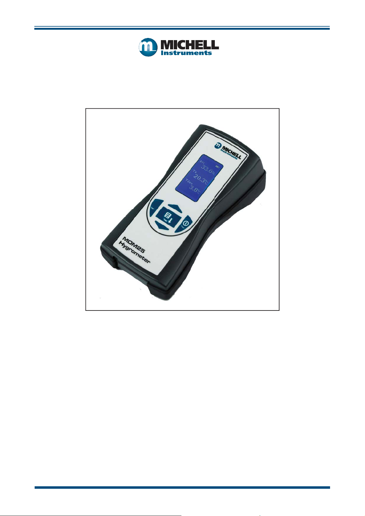
MDM25
Hygrometer
User’s Manual
RH
53.1%
Ta
21.0°C
3
Abs H
9.7
g:M
MDM25
Hygrometer
97234 Issue 4
January 2018
Page 2

Please fi ll out the form(s) below for each instrument that has been purchased.
Use this information when contacting Michell Instruments for service purposes.
Instrument
Code
Serial Number
Invoice Date
Location of Instrument
Tag No
Instrument
Code
Serial Number
Invoice Date
Location of Instrument
Tag No
Instrument
Code
Serial Number
Invoice Date
Location of Instrument
Tag No
Page 3
MDM25
For Michell Instruments' contact information please go to
www.michell.com
© 2018 Michell Instruments
This document is the property of Michell Instruments Ltd. and may not be copied or
otherwise reproduced, communicated in any way to third parties, nor stored in any Data
Processing System without the express written authorization of Michell Instruments Ltd.
Page 4

MDM25 User’s Manual
Contents
Safety ................................................................................................................................vi
Electrical Safety ...........................................................................................................vi
Pressure Safety ............................................................................................................vi
Toxic Materials .............................................................................................................vi
Repair and Maintenance ...............................................................................................vi
Calibration ...................................................................................................................vi
Safety Conformity ........................................................................................................vi
Abbreviations .....................................................................................................................vii
Warnings ...........................................................................................................................vii
1 INTRODUCTION ................................................................................................1
1.1 Description ........................................................................................................ 2
1.1.1 Controls and Indicators ................................................................................. 2
1.1.2 Instrument Display ........................................................................................ 3
1.2 Display Units ...................................................................................................... 4
1.3 Display Settings .................................................................................................. 4
1.4 Device Settings .................................................................................................. 4
1.5 About ................................................................................................................ 4
2 INSTALLATION ..................................................................................................5
2.1 Unpacking the Instrument ................................................................................... 5
2.2 MDM25 Accessories ............................................................................................ 5
2.3 Battery Requirements ......................................................................................... 6
2.3.1 Fitting the Batteries ....................................................................................... 6
2.4 Mounting and Connecting the Probe .................................................................... 7
3 OPERATION ......................................................................................................8
3.1 Preparation for Operation .................................................................................... 8
3.2 Overall Menu Structure ....................................................................................... 8
3.2.1 Display Settings ............................................................................................ 9
3.2.2 Device Settings ........................................................................................... 10
3.2.3 About ......................................................................................................... 11
4 MAINTENANCE ...............................................................................................12
4.1 Probe Calibration .............................................................................................. 12
4.2 Cleaning .......................................................................................................... 12
4.3 Probe Replacement ........................................................................................... 12
4.4 Batteries .......................................................................................................... 12
iv 97234 Issue 4, January 2018
Page 5

MDM25 User’s Manual
Figures
Figure 1 Controls and Indicators ...............................................................................2
Figure 2 Display ......................................................................................................3
Figure 3 Battery Compartment Location ....................................................................6
Figure 4 Probe Connections ......................................................................................7
Figure 5 Main Menu Structure ..................................................................................8
Figure 6 Display Settings Menu .................................................................................9
Figure 7 Device Settings Menu ...............................................................................10
Figure 8 About Menu .............................................................................................11
Tables
Table 1 Unit Descriptions .........................................................................................4
Appendices
Appendix A Technical Specifi cations .............................................................................. 14
Appendix B Quality, Recycling & Warranty Information ...................................................16
Appendix C Analyzer Return Document & Decontamination Declaration .......................... 18
Michell Instruments v
Page 6

MDM25 User’s Manual
Safety
The manufacturer has designed this equipment to be safe when operated using the procedures
detailed in this manual. The user must not use this equipment for any other purpose than that
stated. Do not apply values greater than the maximum value stated.
This manual contains operating and safety instructions, which must be followed to ensure the safe
operation and to maintain the equipment in a safe condition. The safety instructions are either
warnings or cautions issued to protect the user and the equipment from injury or damage. Use
competent personnel using good engineering practice for all procedures in this manual.
Electrical Safety
The instrument is designed to be completely safe when used with options and accessories supplied
by the manufacturer for use with the instrument.
Pressure Safety
This product is not suitable for use at pressures greater than atmospheric.
Toxic Materials
The use of hazardous materials in the construction of this instrument has been minimized. During
normal operation it is not possible for the user to come into contact with any hazardous substance
which might be employed in the construction of the instrument. Care should, however, be exercised
during maintenance and the disposal of certain parts.
Repair and Maintenance
The instrument must be maintained either by the manufacturer or an accredited service agent. Refer
to www.michell.com for details of Michell Instruments’ worldwide offi ces contact information.
Calibration
An annual calibration is recommended for the RH probe. This should be returned to the manufacturer,
Michell Instruments, or one of their accredited service agents for re-calibration.
Safety Conformity
This product meets the essential protection requirements of the relevant EU directives.
vi 97234 Issue 4, January 2018
Page 7

MDM25 User’s Manual
Abbreviations
The following abbreviations are used in this manual:
Abs H absolute humidity
ºC degrees Celsius
ºF degrees Fahrenheit
LCD liquid crystal display
g grams
3
grams per cubic meter
g/m
lb pound
mm millimeters
oz ounce
RH relative humidity
sec second(s)
T temperature
Ta ambient temperature
Td dew point
Tw wet bulb temperature
V Volts
% percentage
Warnings
The following general warnings listed below are applicable to this instrument. They are
repeated in the text in the appropriate locations.
Where this hazard warning symbol appears in the following
sections it is used to indicate areas where potentially
hazardous operations need to be carried out.
Michell Instruments vii
Page 8

MDM25 User’s Manual
1 INTRODUCTION
The MDM25 is a battery operated handmeter.
INTRODUCTION
Available with a number of different probe confi gurations and the ability to display
relative humidity, temperature, absolute humidity (g/m
temperature, the MDM25 is suitable for spot-checking humidity in a wide variety of
applications.
The hygrometer is contained within a molded ABS housing with a rubber surround for
drop protection - sealed to IP54 standards. The rubber surround allows for comfortable
hand-held operation and safe transportation of the unit.
It is powered by 3 alkaline ‘AA’ size cells, which are designed to last a minimum of 150
continuous hours between replacement. Continuous battery charge status indication is
provided by a battery indicator icon.
A graphical display presents the RH and temperature readings, in addition to a selectable
third value, in large format characters.
3
), dew point and wet bulb
Michell Instruments 1
Page 9
INTRODUCTION
1.1 Description
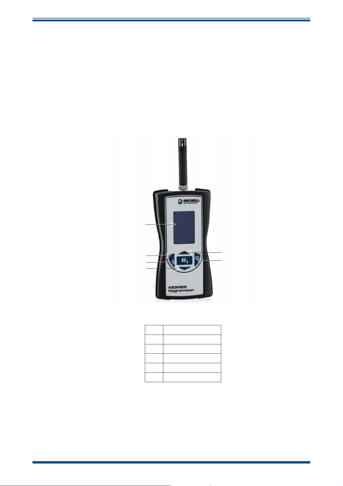
1.1.1 Controls and Indicators
The controls and indicators associated with the MDM25 hygrometer are located on the
front panel.
The probe connection to the MDM25 hygrometer is made to the top panel, and the
battery charger cover is located on the rear of the instrument.
MDM25 User’s Manual
Figure 1
shows the layout of the controls.
1
2
3
4
h
h
h
h
h
h
5
6
1 Display
2 Left and Exit Key
3 Enter Key
4 Down Key
5 Up Key
6 Power Key
Figure 1
Controls and Indicators
2 97234 Issue 4, January 2018
Page 10

MDM25 User’s Manual
1.1.2 Instrument Display
INTRODUCTION
RH
2
h
h
1
53.1%
3
Ta
h
21.0°C
Abs H
4
h
9.7
Battery Charge Indicator Icon - displays 3 dots
1
when full. When battery icon is empty, replace
the batteries.
2 RH Display
3
g:M
3 Temperature Display
3rd Output Display - presents the selected 3rd
4
output, either in ºC / ºF Td, g/m
3
, or ºC / ºF T
Battery Indicator
Full battery power
2/3 battery power
1/3 battery power
Replace batteries
Figure 2
Display
W
Michell Instruments 3
Page 11

INTRODUCTION
1.2 Display Units
The MDM25 measures relative humidity and temperature. The third output, when
displayed, is calculated from these two parameters.
MDM25 User’s Manual
The table below gives a description of all available units.
Signal Symbol Units Description
The ratio of water vapor pressure to the
saturation water vapor pressure (the
Relative Humidity RH %
Temperature Ta ºC or ºF
Dew Point Td ºC or ºF
Absolute Humidity Abs H g/m
maximum amount of water vapor that can
exist at a given temperature) over a liquid
water surface, expressed as a percentage.
The temperature of a gas determines the
maximum quantity of moisture that can
be present as vapor in that gas.
The temperature at which dew, or
condensation, forms, on cooling a gas.
This is, therefore, the temperature at
which air becomes saturated in equilibrium
with water.
The mass of water vapor present in unit
volume of moist air of a given temperature
3
and pressure. SI (metric) units are grams
of water per cubic meter of air (g/m3).
Wet Bulb
temperature
1.3 Display Settings
The Display Settings Menu contains options to change the contrast ratio, backlight
intensity and orientation of the display.
1.4 Device Settings
The Device Settings Menu contains options to change the period of time before poweroff, temperature units and 3rd value units.
1.5 About
The About Menu gives information about the fi rmware version and serial number of the
hygrometer.
Temperature indicated by a thermometer
Tw ºC or ºF
Table 1 Unit Descriptions
sheathed in wet wicking, and infl uenced by
the rate of evaporation from the wicking.
4 97234 Issue 4, January 2018
Page 12

MDM25 User’s Manual
2 INSTALLATION
2.1 Unpacking the Instrument
Open the box carefully and unpack the contents. Check that the following items are
included. Report any shortages immediately.
• MDM25 Hygrometer
• 3 off Alkaline ‘AA’ cells
• User Manual
• RH & Temp Probe (options available)
• Calibration certifi cate (optional)
2.2 MDM25 Accessories
INSTALLATION
Filters and Protection Caps
For 12mm probe For 19mm probe
Slotted protection cap, black Slotted protection cap, black
Mesh fi lter Mesh fi lter
Flat SS sintered dust fi lter Flat SS sintered dust fi lter
Arrow 20μm SS sintered fi lter Arrow 10μm SS sintered fi lter
Arrow 20μm SS sintered fi lter
Probes
• Fixed probe
• Standard probe
• Sword type probe
• Remote high temperature probe, 300mm (18”)
• Remote high temperature probe, 500mm (19.6”)
PVDF fi lter
Other
• Carrying case
• Batteries (3 ‘AA’ Alkaline cells)
• Control Kit of calibration salts
Michell Instruments 5
Page 13

INSTALLATION
2.3 Battery Requirements
The MDM25 is supplied with 3 Alkaline ‘AA’ size cells. These non-rechargeable Alkaline
cells have a high energy density and long shelf-life.
2.3.1 Fitting the Batteries
Unscrew the battery compartment and insert the three ‘AA’ cells, according to the image
on the inside of the battery compartment.
MDM25 User’s Manual
Do not mix different type of batteries.
All three batteries must be of the same type.
Refi t the compartment cover ensuring the seal is fully compressed.
Figure 3
Battery Compartment Location
6 97234 Issue 4, January 2018
Page 14

MDM25 User’s Manual
2.4 Mounting and Connecting the Probe
All probes insert directly into the connector on the top of the MDM25.
Align the locating peg with the locating notch and then rotate the knurled thumb wheel
until the probe is securely held in place.
INSTALLATION
Figure 4
Locating Peg
Locating Notch
Probe Connections
WARNING: Do not over-tighten as this could cause damage
to the probe body.
Michell Instruments 7
Page 15

OPERATION
3 OPERATION
3.1 Preparation for Operation
Press the power-on button and observe the readings on the LCD. Some 3rd values may
take a few seconds to calculate, depending upon the %RH and ambient temperature
(Ta).
If using the MDM25 alongside the S503 RH calibrator, adjust the display orientation to
allow for the product to be read correctly when upside down.
If there is there is no reading on the screen check the battery orientation. Replace with
new batteries if required.
3.2 Overall Menu Structure
MDM25 User’s Manual
MAIN MENU
DISPLAY
CONTRAST AUTO OFF TEMP UNITS 3RD VALUE FIRMWARE VERSION
BACKLIGHT
DISPLAY
ORIENTATION
Figure 5
DEVICE
Main Menu Structure
ABOUT
8 97234 Issue 4, January 2018
Page 16

MDM25 User’s Manual
3.2.1 Display Settings
OPERATION
DISPLAY
Press
CONTRAST
Press
Set the contrast for
the display settings
by pressing the Up
and Down Keys
0 = no contrast
5 = full contrast
BACKLIGHT
Press
Set the brightness
of the backlight by
DISPLAY ORIENTATION
Press
The orientation
pressing the Up
and Down Keys
0 = dark
5 = bright
pressing the Up
and Down keys
To store these settings in the memory, press the Menu
button which will open the Main page. When the hand
meter is turned on again this setting is saved.
To store the settings for ONLY the current session, press
the Left Key
Special feature:
of the display
The display
can be rotated
turns automatically
when hand meter
by 180º by
is positioned
upside-down
Figure 6
Display Settings Menu
Michell Instruments 9
Page 17

OPERATION
3.2.2 Device Settings
MDM25 User’s Manual
DEVICE
Press
AUTO OFF
Press
To save battery life the
Auto O automatically
switches o the device if
it is not in use.
By pressing the Up and
Down Keys the period of
inactive time before
power-o can be set to
between 1 and 20
minutes or disabled
entirely.
Steps of 1 min up to 10
Steps of 5 mins from 10
to 20
∞ - AUTO OFF disabled
TEMP UNITS
Press
By pressing the Up
and Down Keys
temperature units
can be selected as
either Celcius or
Fahrenheit
3RD VALUE
Press
By pressing the Up
and Down Keys the
3rd value option can
be set to read:
Dew point
Abs Hum
Wet Bulb or
None
To store these settings in the memory, press the Menu
button to return to the Main page. When the hand meter
is turned on again this setting is saved.
To store the settings for ONLY the current session, press
the Left Key
Figure 7
Device Settings Menu
10 97234 Issue 4, January 2018
Page 18

MDM25 User’s Manual
3.2.3 About
OPERATION
ABOUT
Press
FIRMWARE VERSION
Press
View the rmware
version and serial
number of the hand
meter.
This number relates to
the hand held unit ONLY,
not the attached probe
Press the Menu button to return to the Main page.
Figure 8
About Menu
Michell Instruments 11
Page 19

MAINTENANCE
4 MAINTENANCE
The MDM25 is designed to operate either in static ambient conditions, or in a fl owing
gas stream.
The sensors are designed to have excellent performance in ambient conditions.
Therefore, a fl ow is not necessary to ensure that the probe is reacting rapidly to changes
in measured conditions.
If the sensor is installed in a fl owing sample, then it is not crucial to regulate the
fl ow rate in order to ensure consistent performance, although it is preferable to avoid
excessive fl ow rates past the sensor during operation.
The use of appropriate fi ltering for the sample conditions is always recommended – so,
where the sample or ambient conditions may contain dust, steam or liquid water, a
suitable mesh or sintered fi lter should be fi tted. Protection caps are also available to
defend against the possibility of handling damage.
Care should be taken to avoid mechanical shock (impact) or thermal shock (sudden
temperature changes).
MDM25 User’s Manual
4.1 Probe Calibration
Salt solutions are commonly used for the calibration of RH sensors. Michell Instruments’
calibration Control Kit is available to provide a traceable reference to verify the accuracy
of the probe.
The Control Kit can be purchased from Michell Instruments (for contact information go
to www.michell.com).
4.2 Cleaning
The enclosure can be cleaned using a mild household detergent and a damp soft cloth
or absorbent paper. Remove the connector before cleaning and dry off any moisture
before reassembly. NOTE: Do not use any abrasives - this may cause the LCD
display to become obscured.
4.3 Probe Replacement
The probe should be returned to Michell Instruments annually for recalibration. This
will ensure continued traceability, and will verify that it is still performing within its
specifi ed accuracy.
4.4 Batteries
When the battery charge indicator icon on the display is empty, the batteries should be
replaced (see Section 2.3). Always install 3 new batteries of the same type.
12 97234 Issue 4, January 2018
Page 20

MDM25 User’s Manual
APPENDIX A
Appendix A
Technical Specifi cations
Michell Instruments 13
Page 21

APPENDIX A
MDM25 User’s Manual
Appendix A Technical Specifi cations
HYGROMETER
Performance
Measurement Units %RH, ºC / ºF Ta, ºC / ºF Td, g/m3, ºC / ºF Tw
Mechanical Specifi cation
Ingress Protection IP54
Hygrometer Housing Material Molded polymer housing ABS + rubber surround
Weight 300g (10.58oz)
Display Resolution Graphic LCD 128 x 64 pixels
Electrical Output/Input
Supply Voltage
Electrical Connections M9 5-way binder connector
PROBES
Performance
Measurement Range (RH) 0 - 100% RH
Accuracy at 25ºC (77ºF)
Temperature
Stability - RH Sensor ±1% RH/year
Response time - RH Sensor <10 sec typical (for 90% of the step change)
Measurement & Operating
Range (T)
- Fixed and Standard Probe
- Sword Probe
- Remote Probe
Accuracy at 25ºC (77ºF)
Humidity
- Fixed Probe
- Remote Probe
4.5 V
(3 x ‘AA’ batteries - provide approximately 150 hours of operation)
±0.2ºC (±0.36ºF)
-20 to +80ºC (-4 to +176ºF)
-20 to +100ºC (-4 to +212ºF)
-20 to +150ºC (-4 to +302ºF)
±2% RH (10 - 90% RH)
±2% RH (5 - 95% RH)
Mechanical Specifi cation
Weight
Fixed Probe
Standard Probe
Sword Probe
High Temp 300mm Probe
High Temp 500mm Probe
FPR
SPR
SWPR
HTPR300
HTPR500
30g (1.06 oz)
90g (3.17 oz)
500g (1.1 lb)
380g (13.4 oz)
620g (1.37 lb)
14 97234 Issue 4, January 2018
Page 22

MDM25 User’s Manual
Appendix B
APPENDIX B
Quality, Recycling
& Warranty
Information
Michell Instruments 15
Page 23

APPENDIX B
MDM25 User’s Manual
Appendix B Quality, Recycling & Warranty Information
Michell Instruments is dedicated to complying to all relevant legislation and directives. Full information
can be found on our website at:
www.michell.com/compliance
This page contains information on the following directives:
• ATEX Directive
• Calibration Facilities
• Confl ict Minerals
• FCC Statement
• Manufacturing Quality
• Modern Slavery Statement
• Pressure Equipment Directive
• REACH
• RoHS2
• WEEE2
• Recycling Policy
• Warranty and Returns
This information is also available in PDF format.
16 97234 Issue 4, January 2018
Page 24

MDM25 User’s Manual
Appendix C
APPENDIX C
Analyzer Return Document
&
Decontamination Declaration
Michell Instruments 17
Page 25

APPENDIX C
MDM25 User’s Manual
Appendix C Analyzer Return Document & Decontamination Declaration
'HFRQWDPLQDWLRQ&HUWL¿FDWH
IMPORTANT NOTE: Please complete this form prior to this instrument, or any components, leaving your
site and being returned to us, or, where applicable, prior to any work being carried out by a Michell
engineer at your site.
Instrument Serial Number
Warranty Repair? YES NO Original PO #
Company Name Contact Name
Address
Telephone # E-mail address
Reason for Return /Description of Fault:
Has this equipment been exposed (internally or externally) to any of the following?
Please circle (YES/NO) as applicable and provide details below
Biohazards YES NO
Biological agents YES NO
Hazardous chemicals YES NO
Radioactive substances YES NO
Other hazards YES NO
Please provide details of any hazardous materials used with this equipment as indicated above (use continuation sheet
if necessary)
Your method of cleaning/decontamination
Has the equipment been cleaned and decontaminated? YES NOT NECESSARY
Michell Instruments will not accept instruments that have been exposed to toxins, radio-activity or bio-hazardous
PDWHULDOV)RUPRVWDSSOLFDWLRQVLQYROYLQJVROYHQWVDFLGLF EDVLFÀDPPDEOHRUWR[LFJDVHVDVLPSOHSXUJHZLWK GU\
JDVGHZSRLQW&RYHUKRXUVVKRXOGEHVXI¿FLHQWWRGHFRQWDPLQDWHWKHXQLWSULRUWRUHWXUQ
Work will not be carried out on any unit that does not have a completed decontamination declaration.
Decontamination Declaration
I declare that the information above is true and complete to the best of my knowledge, and it is safe for Michell
personnel to service or repair the returned instrument.
Name (Print) Position
Signature Date
F0121, Issue 2, December 2011
18 97234 Issue 4, January 2018
Page 26

Page 27

EU Declaration of Conformity
Manufacturer: Michell Instruments B.V.
Krombraak 11
4906 CR Oosterhout
The Netherlands.
We declare under our sole responsibility that the product:
MDM25 Hygrometer
complies with all the essential requirements of the EU directives listed below.
2014/30/EU EMC Directive
2011/65/EU Restriction of Hazardous Substances Directive
(RoHS2)
Using the standards:
EN61326-1:2013 Electrical equipment for measurement, control and laboratory use
EMC requirements – Group 1, Class B equipment (emissions)
and Portable Equipment (immunity).
and has been designed to be in conformance with the relevant sections of the following standards or other
normative documents.
EN61010-1:2010
Safety Requirements for Electrical Equipment for
Measurement, Control, and Laboratory Use - Part 1:
General Requirements
EN60529
Degrees of Protection Provided by Enclosures.
Ingress Rating equivalent to IP54
Robert-Jan Pouw RH Business Manager.
Michell Instruments Benelux B.V. Oosterhout The Netherlands
Date of Issue 6 December 2017
___________________________________
on behalf of
Peter Haakma Managing Director Michell Instruments Benelux B.V.
EUD MDM25 Issue 04
Page 28

http://www.michell.com
 Loading...