

Page 1

Hygrosmart HS3
Advanced RH & Temperature Probe
User’s Manual
97516 Issue 5
July 2017
Page 2

Please fi ll out the form(s) below for each instrument that has been purchased.
Use this information when contacting Michell Instruments for service purposes.
Instrument
Code
Serial Number
Invoice Date
Location of Instrument
Tag No
Instrument
Code
Serial Number
Invoice Date
Location of Instrument
Tag No
Instrument
Code
Serial Number
Invoice Date
Location of Instrument
Tag No
Page 3

HygroSmart HS3 Probe
For Michell Instruments' contact information please go to
www.michell.com
© 2017 Michell Instruments
This document is the property of Michell Instruments Ltd. and may not be copied or
otherwise reproduced, communicated in any way to third parties, nor stored in any Data
Processing System without the express written authorization of Michell Instruments Ltd.
Page 4

HygroSmart HS3 User’s Manual
Contents
Safety ................................................................................................................................vi
Electrical Safety ...........................................................................................................vi
Toxic Materials .............................................................................................................vi
Repair and Maintenance ...............................................................................................vi
Calibration ...................................................................................................................vi
Safety Conformity ........................................................................................................vi
Abbreviations .....................................................................................................................vii
Warnings .......................................................................................................................... viii
1 INTRODUCTION ................................................................................................1
1.1 Operating Flexibility ............................................................................................ 1
2 INSTALLATION ..................................................................................................2
2.1 Unpacking .......................................................................................................... 2
2.2 Probe Layout ...................................................................................................... 2
2.3 Maintenance Kits ................................................................................................ 3
2.4 Installation Instructions ...................................................................................... 4
2.4.1 Recommended Installation Environment ......................................................... 4
2.4.2 Element Filter Assembly Environment ............................................................. 4
2.4.3 Probe Wall Mounting ..................................................................................... 5
2.4.4 Duct Mounting .............................................................................................. 5
2.4.5 Pressurized Environment Installation .............................................................. 6
2.4.6 Electrical Requirements ................................................................................. 7
2.4.7 Electrical Connections .................................................................................... 7
2.4.8 Digital Serial Output ...................................................................................... 7
2.4.9 Analog Voltage Outputs ................................................................................. 7
2.4.10 Probe Ordered Confi guration .......................................................................... 8
2.4.11 Probe Reconfi guration ................................................................................... 8
2.4.12 Probe & Sensor Serialization Tracking ............................................................. 8
3 PROBE MAINTENANCE KIT OPERATION ..............................................................9
3.1 Application Software Overview ............................................................................ 9
3.2 Installation ......................................................................................................... 9
3.3 Establishing Communications .............................................................................. 9
3.4 Measurement Data Acquisition .......................................................................... 10
3.5 Probe Confi guration .......................................................................................... 11
3.6 Probe Adjustment ............................................................................................. 12
3.7 Loop Checking Simulation ................................................................................. 18
4 SENSOR REPLACEMENT ...................................................................................19
5 LOOP CHECKING SIMULATION .........................................................................21
5.1 Simulator Connection ........................................................................................ 21
5.2 Checking /Programming the Simulators ............................................................ 21
6 MAINTENANCE ................................................................................................22
6.1 Cleaning the Filter Element ............................................................................... 22
6.2 Probe Adjustment Procedure ............................................................................. 23
97516 Issue 5, July 2017
iv
Page 5

HygroSmart HS3 User’s Manual
Figures
Figure 1 HygroSmart HS3 Probe and Interchangeable Sensor .....................................1
Figure 2 HygroSmart HS3 Probe Packaging ...............................................................2
Figure 3 HygroSmart HS3 Probe Layout ....................................................................2
Figure 4 Acceptable Operating Conditions .................................................................4
Figure 5 Mounting Clamp (HS3-PMC) ........................................................................5
Figure 6 Probe Wall Mounting ...................................................................................5
Figure 7 Duct Mounting ...........................................................................................5
Figure 8 Probe Metal Gland ......................................................................................6
Figure 9 Securing Tether ..........................................................................................6
Figure 10 Electrical Connections .................................................................................7
Figure 11 Connection Console Screen Shot ..................................................................9
Figure 12 Probe and Sensor Information Screen Shot ................................................10
Figure 13 Measurement Data Acquisition Screen Shot ................................................10
Figure 14 Output Channel Example Screen Shot ........................................................11
Figure 15 Probe Confi guration Screen Shot ...............................................................11
Figure 16 Probe Adjustment Screen Shot ..................................................................12
Figure 17 Probe readings prior to adjustment ............................................................13
Figure 18 Editing the Adjustment Table .....................................................................14
Figure 19 Probe readings post-adjustment ................................................................14
Figure 20 Probe readings prior to adjustment ............................................................15
Figure 21 Editing the Adjustment Table .....................................................................15
Figure 22 Probe readings post-adjustment ................................................................16
Figure 23 Probe readings prior to adjustment ............................................................16
Figure 24 Editing the Adjustment Table .....................................................................17
Figure 25 Probe readings post-adjustment ................................................................17
Figure 26 Simulator Window Screen Shot ..................................................................18
Figure 27 Sensor Simulator ......................................................................................21
Figure 28 Filter Cap Removal ...................................................................................22
Figure 29 Filter Element Cleaning .............................................................................22
Figure 30 Dimensional Drawings...............................................................................26
Figure 32 Serial Port Parameters ..............................................................................28
Figure 31 Pinout ......................................................................................................28
Appendices
Appendix A Technical Specifi cations .............................................................................. 25
A.1 Dimensions ................................................................................. 26
Appendix B HS3 Modbus Communications and Register Map .......................................... 28
B.1 Communications .......................................................................... 28
B.2 Code examples ............................................................................ 29
B.3 Register Map ............................................................................... 30
Appendix C Quality, Recycling & Warranty Information ...................................................37
Appendix D Return Document & Decontamination Declaration ........................................ 39
Michell Instruments
v
Page 6

HygroSmart HS3 User’s Manual
Safety
The manufacturer has designed this equipment to be safe when operated using the procedures
detailed in this manual. The user must not use this equipment for any other purpose than that
stated. Do not apply values greater than the maximum value stated.
This manual contains operating and safety instructions, which must be followed to ensure the safe
operation and to maintain the equipment in a safe condition. The safety instructions are either
warnings or cautions issued to protect the user and the equipment from injury or damage. Use
competent personnel using good engineering practice for all procedures in this manual.
Electrical Safety
The instrument is designed to be completely safe when used with options and accessories supplied
by the manufacturer for use with the instrument.
Toxic Materials
The use of hazardous materials in the construction of this instrument has been minimized. During
normal operation it is not possible for the user to come into contact with any hazardous substance
which might be employed in the construction of the instrument. Care should, however, be exercised
during maintenance and the disposal of certain parts.
Repair and Maintenance
The instrument must be maintained either by the manufacturer or an accredited service agent. For
Michell Instruments’ contact information please go to www.michell.com.
Calibration
HS3 Probes are adjusted in the factory prior to delivery. Recalibration is recommended after one
year of operation, depending on application. New, freshly calibrated sensors can be supplied quickly
by Michell Instruments, or recalibration can be carried out on site using one of the Michell humidity
calibration systems. Refer to Section 6.2 regarding calibration checking and adjustment of probes.
Safety Conformity
This product meets the essential protection requirements of the relevant EU standards and directives.
97516 Issue 5, July 2017
vi
Page 7

HygroSmart HS3 User’s Manual
Abbreviations
The following abbreviations may be used in this manual:
barg pressure unit (=100 kP or 0.987 atm) gauge
°C degrees Celsius
°F degrees Fahrenheit
EU European Union
g grams
3
grams per cubic metre
g/m
kg kilograms
Kj/kg kilojoules per kilogram
lb pound
mm millimetre
oz ounce
RH relative humidity
RS485 serial data transmission standard
RTU Remote Terminal Unit
T temperature
V Volts
V DC Volts of direct current
% percentage
" inch
ø diameter
Michell Instruments
vii
Page 8

HygroSmart HS3 User’s Manual
!
Warnings
The following general warning listed below is applicable to this instrument. It is repeated in the text
in the appropriate locations.
Where this hazard warning symbol appears in the following sections, it
is used to indicate areas where potentially hazardous operations need to
be carried out.
97516 Issue 5, July 2017
viii
Page 9

HygroSmart HS3 User’s Manual
1 INTRODUCTION
The HygroSmart HS3 is an accurate, stable and user confi gurable probe designed to
provide reliable relative humidity measurement for process control in a wide range
of applications. The HS3 Probe features interchangeable sensor technology ensuring
minimal process downtime and a low cost of ownership.
INTRODUCTION
Figure 1
1.1 Operating Flexibility
The HS3 Probe has been developed to be 100% customer confi gurable. One stock unit
can be set up by a customer into an application specifi c confi guration to cover any RH
demands on site. This fl exibility saves time and budget.
• Adjustable zero/span ranging of the RH, Temperature and Calculated
Hygrometric Outputs
• Selectable 0 to 1, 2.5, 5, 10 V output signals
• 2 selectable output voltage measured (RH & T) parameters or a choice of
5 calculated parameters (eg dew point)
• Addressable Modbus RTU over RS485 communications for up to 32 probes
• Probe digital Zero/Span calibration trimming
HygroSmart HS3 Probe and Interchangeable Sensor
Alternatively, the HS3 Probe can be confi gured at the factory at time of ordering for
customers who want a simple fi xed confi guration solution.
Michell Instruments
1
Page 10

INSTALLATION
2 INSTALLATION
2.1 Unpacking
Open the cardboard box and remove the plastic tray inside.
HygroSmart HS3 User’s Manual
Please check that the following components are present:
• HygroSmart HS3 Probe (with the interchangeable HygroSmart HS3 sensor)
• Certifi cate of Calibration
• Quick Start Guide
• User Manual
2.2 Probe Layout
The HS3 Probe with its constituent parts and physical features is detailed in the layout
below:
1 23456
Figure 2
HS3-PE PAA-000002 HS3-PE PAA-000001
HygroSmart HS3 Probe Packaging
98.5mm
HygroSmart HS3 Probe Electronics HygroSmart HS3 Interchangeable Sensor
3.87”
1 M12 5-pin probe electrical connector
2 Probe serial number
3 Probe to sensor connector alignment marks
4 Rotating probe cuff
5 Sensor serial number
6 Filter assembly
Figure 3
97516 Issue 5, July 2017
2
HygroSmart HS3 Probe Layout
Page 11

HygroSmart HS3 User’s Manual
2.3 Maintenance Kits
INSTALLATION
HS3-SCK
HS3 Probe Simulator Kit
Includes:
- Desk-mounted confi guration kit with 1.8m cable
- 3 sensor simulators (25%, 50%, 75%RH at 23°C (73°F))
- Spare probe electronics
- Carry case
HS3-CK
HS3 Probe Confi guration Kit
Includes:
- Desk-mounted confi guration kit with 1.8m cable
- Spare probe electronics
- Carry case
HS3-CKL
HS3 Logger/Confi guration Converter Cable 1.8 meters
Includes:
- 1.8 meter USB to RS485 converter cable with M12
connector
Michell Instruments
3
Page 12

INSTALLATION
2.4 Installation Instructions
2.4.1 Recommended Installation Environment
When choosing an installation site for the probe, consider the environment around it.
Ensure that the site:
• is clear of nearby obstructions which could limit air circulation to the
probe
• is away from any hot or cold spots - i.e. air conditioning or heater vents
• is not adjacent to any high power sources
• is representative of the surrounding environment at the point of interest
HygroSmart HS3 User’s Manual
The acceptable operating conditions for the sensor are detailed in
RH%
100
75
50
25
Figure 4
Maximum mixing ratio
250g water/kg dry air
Temp °C
-40 0 5025 70 85
Acceptable Operating Conditions
Figure 4
.
2.4.2 Element Filter Assembly Environment
The PVDF fi lter element protects the sensor against particulate contamination and the
effects of high velocity air-fl ow.
To ensure good air-fl ow to the sensor it is recommended to regularly clean the fi lter
element. See Section 6.1 for more details.
The HS3 Probe can be equipped with the following fi lter model
• F1 - PVDF (12mm diameter) black cap assembly
• F2 - 13mm (0.51”) HDPE protection cap
97516 Issue 5, July 2017
4
Page 13

HygroSmart HS3 User’s Manual
2.4.3 Probe Wall Mounting
A mounting clamp for the HS3 Probe (HS3-PMC) can be ordered as an accessory.
INSTALLATION
Figure 5
Mounting Clamp (HS3-PMC)
The clamp can be used to securely hold the probe body, and provides a 1/4" 20 UNC
thread to mount it to a fi xed surface.
It is recommended that the HygroSmart HS3 Probe is installed with the sensor and fi lter
assembly facing downwards.
55.5mm
2.19”
HS3-PE PAA-000002 HS3-PE PAA-000002
Figure 6
Probe Wall Mounting
2.4.4 Duct Mounting
When installing the HS3 Probe into a duct, ensure that the probe is inserted as far as
possible into the environment to be measured.
If the measurement environment is pressurized, then follow the guidelines in 2.4.5.
Michell Instruments
5
HS3-PE PAA-000002 HS3-PE PAA-000002
55.5mm
2.19”
Figure 7
Duct Mounting
HS3-PE PAA-000002 HS3-PE PAA-000002
55.5mm
2.19”
Page 14

INSTALLATION
HS3
000002
!
2.4.5 Pressurized Environment Installation
The HS3 Probe is a solid assembly with no internal air cavities; this ensures that an
external pressure of up to 10 barg will cause no damage to the probe.
The probe can be installed into pressurized environments by two different methods:
1. Through a vessel or duct wall using the Probe Metal Gland sealing
accessory.
2. Mounted entirely within the pressurized vessel.
HygroSmart HS3 User’s Manual
The Probe Metal Gland (HS3-PMG) is shown in
Figure 6.
It is designed to be installed in
the wall of the pressure vessel by the M25 x 1.5 thread on the rear (1). The O-ring (2)
provides the pressure seal. The probe can then be installed, and the gland tightened
until the shaft of the probe rotates with the turn of the nut.
2
1
Figure 8
Probe Metal Gland
For safety, always ensure that the probe is tethered to the vessel wall or the gland itself.
A tether can be attached to the probe around the base of the M12 mating connector,
see
Figure 7 f
or details.
HS3-PE PAA-000002
-PE PAA-
Figure 9
Securing Tether
When installing probe using the sealing gland, always ensure
that the securing tether is fi tted before applying pressure!
97516 Issue 5, July 2017
6
Page 15

HygroSmart HS3 User’s Manual
2.4.6 Electrical Requirements
The HygroSmart HS3 Probe requires a supply voltage from 5 to 28 V DC.
2.4.7 Electrical Connections
The electrical connections, as seen when looking at the base of the probe, are shown
in the following schematic:
OPERATION
Modbus Analog Cable Color
1 Comms A Output 1 Brown
2 Comms B Output 2 White
3 0 V N/C Blue
4 +5 V to +28 V +5 V to +28 V Black
5 0 V 0 V Gray
Note: M12 mating connector/cables are not supplied with the Probe, but can
be ordered as an accessory. They are available in 2, 5 & 10 meter lengths.
2.4.8 Digital Serial Output
The connections for Modbus RTU over RS485 communications are detailed in
In order to enable digital comms, both pins 3 & 5 should be grounded. See Appendix B for
mire details.
Figure 10
Electrical Connections
21
5
34
Figure
10.
NOTE: The probe will not output digital and voltage signals simultaneously.
2.4.9 Analog Voltage Outputs
The HS3 Probe will be set up, when ordered, to one of the following selection of voltage
outputs:
These voltage outputs can be reconfi gured at any time using one of the available
Maintenance Kits, in conjunction with the HS3 Probe Application Software.
0 - 1 V
0 - 2.5 V
0 - 5 V
0 - 10 V
Michell Instruments
7
Page 16

OPERATION
2.4.10 Probe Ordered Confi guration
The confi guration code of the HS3 Probe, when ordered, defi nes its precise set up. This
is detailed on the order acknowledgement & invoice documents.
2.4.11 Probe Reconfi guration
If at any point in time the HS3 Probe needs reconfi guration, this can be achieved quickly
and easily by using any of the available Maintenance Kits, in conjunction with the HS3
Probe Application Software.
2.4.12 Probe & Sensor Serialization Tracking
The HS3 Probe and associated interchangeable sensor have a unique serial number and
bar code identifi cation on the body of the devices. These serial numbers are also stored
within the sensor and probe electronics and can be accessed using the HS3 Application
Software.
HygroSmart HS3 User’s Manual
97516 Issue 5, July 2017
8
Page 17

HygroSmart HS3 User’s Manual
3 PROBE MAINTENANCE KIT OPERATION
The available Probe Maintenance Kits are detailed in Section 2.3. The operation of the
Maintenance Kits is as follows:
OPERATION
HS3-SCK
HS3-CK
HS3-CKL
Connect the probe to the connector on the desk-mounted confi guration
kit, connect the USB cable to the PC, then follow the setup procedure
detailed in Section 3.3.
Connect the M12 connector to the probe, and the USB cable to the PC
before following the setup procedure.
3.1 Application Software Overview
The HS3 Application Software is downloadable from the Michell website (www.michell.
com).
3.2 Installation
1. Extract the contents of the supplied zip fi le to a suitable location.
2. Close all currently running Windows programs.
3. Launch the installer and follow the on-screen instructions.
3.3 Establishing Communications
On launching the software the connection console will appear.
The connection console
between the software and HS3 Probe. Choose the Modbus slave address and
communications port from the drop-down lists and then click the
After a few seconds the software will report a successful connection, or not. If the
connection is successful, the word
(Figure 9)
allows you to establish a communications connection
Connect... button.
Connected and a green tick will appear above the
Quit button and the Continue button will enable.
If the software is unable to connect, check the physical connection between the probe
and PC, check which com port the adaptor is connected to and try again.
Michell Instruments
Figure 11
9
Connection Console Screen Shot
Page 18

OPERATION
From this window the probe and sensor information can be viewed by clicking the
Probe info. button. Alternatively click the Continue button on the console window to
open the
HygroSmart HS3 User’s Manual
Options window.
Figure 12
Click OK to close the probe information window.
Click the
Continue button on the console window to continue on to the Options window.
Probe and Sensor Information Screen Shot
3.4 Measurement Data Acquisition
This window can be opened from the Options window. As soon as it is opened, the
software automatically begins collecting, displaying and charting live data from the HS3
Probe.
Data collection occurs approximately twice a second. The chart update rate is two
seconds but this may be changed through the chart options window.
Figure 13
97516 Issue 5, July 2017
10
Measurement Data Acquisition Screen Shot
Page 19

HygroSmart HS3 User’s Manual
The two output (Output 1 and Output 2) channel units are highlighted in blue and
green.
OPERATION
In the example in
set to Temperature.
The expected output volts and volts percentage (of full scale) is also displayed here.
Errors and Warnings
When probe errors or warnings are encountered they will be highlighted in the
section and a link will appear.
Click the
View link to launch a new window which details the errors and warnings.
Figure 14
Figure 14
, Output 1 (in blue) is set to RH and Output 2 (in green) is
Output Channel Example Screen Shot
Status
3.5 Probe Confi guration
This screen can be opened from the Options window. Upon opening, the 'current
settings' column is updated with the parameters within the probe.
Michell Instruments
Figure 15
11
Probe Confi guration Screen Shot
Page 20

OPERATION
To change a setting, either choose defi ned values from the drop-down lists or enter
values into the text boxes under the
button to apply the settings.
After applying new settings, the software automatically reads back the probe confi guration
and displays it on screen in the left (current settings) column.
Advanced button takes you to the Probe Adjustment window via a password entry
The
box. Enter the password
3.6 Probe Adjustment
This window provides access to both the RH and temperature calibration tables, and the
probe Modbus address.
Picture below showing the default (factory) settings.
HygroSmart HS3 User’s Manual
Change settings column and then click the Apply
7316 to continue.
Figure 16
To change a value, type within the text boxes provided and click the Apply... button to
apply the new value(s) to the HS3 Probe.
Important : the values in point 1 to 5 must be in ascending order!
Values are checked before they are applied to the HS3 Probe according to a set of rules.
The rules are displayed on the right hand side of the window. The software will display
a warning if any values do not comply with the rules.
Clicking the Read... button reads and display the tables from the HS3 Probe.
Clicking the
Clicking the
RECOMMENDATION: It is a good idea to save the tables before editing them.
You can then Load (retrieve) the saved table in case any mistakes are made.
NOTE: If the Modbus address is changed, the software will continue
communicating with the probe under the new address.
97516 Issue 5, July 2017
12
Save... button saves the tables to a fi le.
Load... button loads the previously saved fi le.xxxxxxx
Probe Adjustment Screen Shot
Page 21

HygroSmart HS3 User’s Manual
The next example will demonstrate a 3 point humidity adjustment.
In this example 30, 50 and 70%RH , but any other point is also possible.
(%RH and Temperature adjustment are done in the same way)
st
Adjustment Point.
1
1. Place the HS3-Probe together with a reference in a controlled and stable
environment of 30%RH.
2. Check the readings of the HS3-probe and the reference.
• The Humidity reference is reading 30.8%RH.
• The HS3-probe reads 28.0%RH.
OPERATION
Figure 17
Probe readings prior to adjustment
3. Find the nearest point in the RH Adjustment table (in this example 30)
and change it into the measured reference value. (in this example 30.8).
4. Subtract the Humidity value of the HS3-probe from the reference value
(30.8 - 28.0 = 2.8).
5. Add the outcome to the reference value (30.8 + 2.8 = 33.6).
6. Enter this value in the corresponding fi eld of Corrected RH.
Michell Instruments
13
Page 22

SENSOR REPLACEMENT
HygroSmart HS3 User’s Manual
After Correction:
Figure 18
Figure 19
Editing the Adjustment Table
Probe readings post-adjustment
2nd Adjustment Point
1. Place the HS3-Probe together with a reference in a controlled and stable
environment of ± 50%RH.
2. Check the readings of the HS3-Probe and the reference.
• The Humidity reference is reading 50.2%RH.
• The HS3-Probe reads 51.3%RH.
97516 Issue 5, July 2017
14
Page 23

HygroSmart HS3 User’s Manual
SENSOR REPLACEMENT
Figure 20
3. Find the nearest point in the RH Adjustment table (in this example 50)
and change it into the measured reference value. (in this example 50.2).
4. Subtract the Humidity value of the HS3-Probe from the reference value
(50.2 – 51.3 = -1.1).
5. Add the outcome to the reference value (50.2 – 1.1 = 49.1).
6. Enter this value in the corresponding fi eld of Corrected RH.
Probe readings prior to adjustment
Michell Instruments
Figure 21
15
Editing the Adjustment Table
Page 24

LOOP CHECKING SIMULATION
After Correction:
HygroSmart HS3 User’s Manual
Figure 22
3rd Adjustment Point.
1. Place the HS3-Probe together with a reference in a controlled and stable
environment of ± 70%RH.
2. Check the readings of the HS3-Probe and the reference.
• The Humidity reference is reading 69.6%RH.
• The HS3-Probe reads 71.3%RH.
Probe readings post-adjustment
Figure 23
3. Find the nearest point in the RH Adjustment table (in this example 70) and
change it to the measured reference value (in this example 69.6%RH).
97516 Issue 5, July 2017
16
Probe readings prior to adjustment
Page 25

HygroSmart HS3 User’s Manual
4. Subtract the Humidity value of the HS3-Probe from the reference value
(69.6 – 71.3 = -1.7).
• Add the outcome to the reference value (69.6 -1.7 = 67.9).
• Enter this value in the corresponding fi eld of Corrected RH.
MAINTENANCE
After Correction:
Figure 24
Figure 25
Editing the Adjustment Table
Probe readings post-adjustment
Michell Instruments
17
Page 26

MAINTENANCE
3.7 Loop Checking Simulation
The simulator window provides a way to change the defi ned outputs on both the RH
and temperature channel.
HygroSmart HS3 User’s Manual
Figure 26
Enter the desired, simulated value(s) into the RH and/or temperature input text boxes
and click the relevant
change accordingly.
The values shown on the left under
To read (refresh the screen) probe values, click the
Apply button to apply the value. The analog output(s) should
Simulator Window Screen Shot
Probe values are read from the probe.
Read button.
97516 Issue 5, July 2017
18
Page 27

HygroSmart HS3 User’s Manual
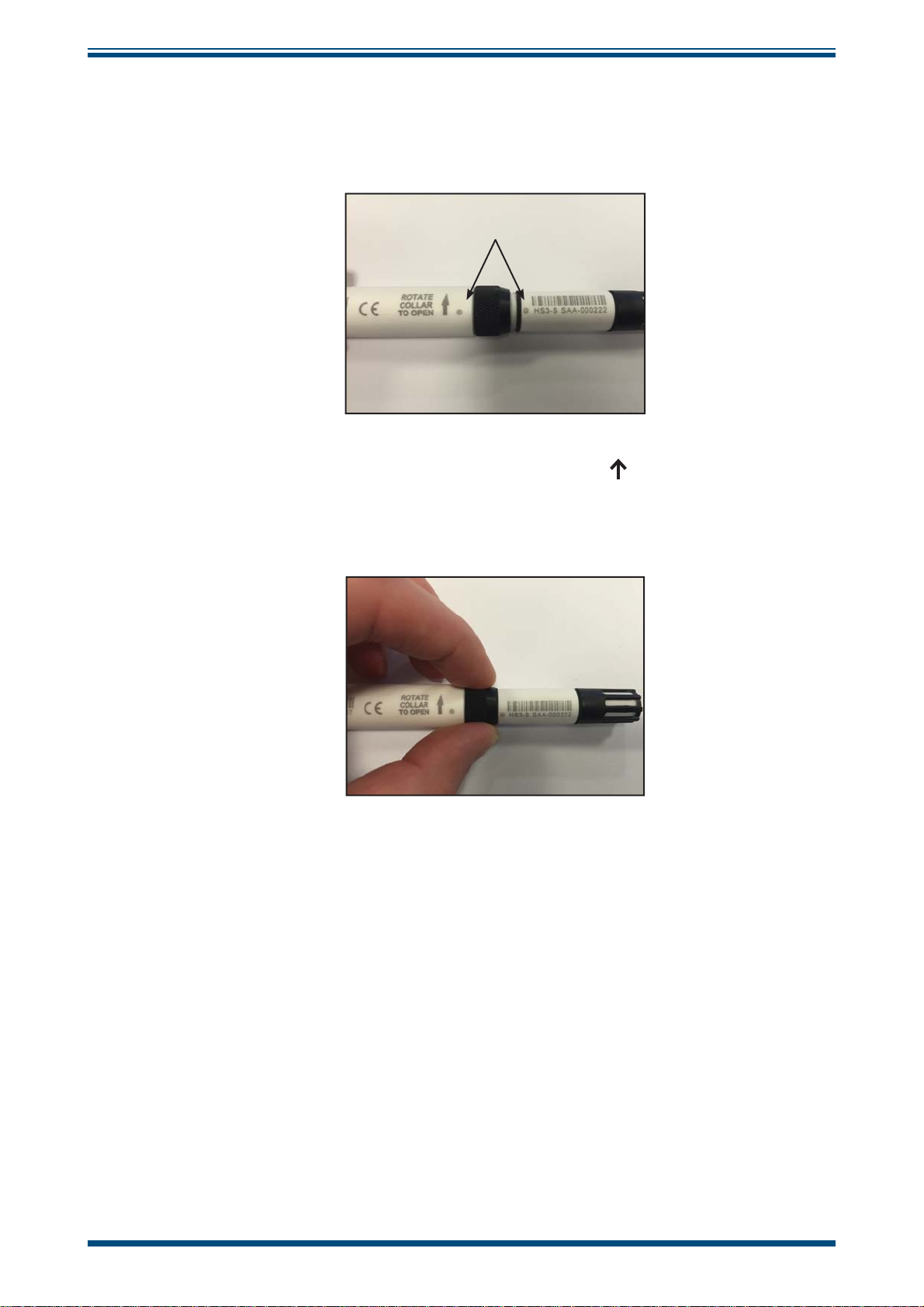
4 SENSOR REPLACEMENT
1. Remove the probe from its mounting position.
2. Remove the M12 connector from the probe.
APPENDIX A
3. Rotate the knurled collar in the direction indicated by the arrow, until
the sensor separates from the probe.
4. Remove the old sensor, and prepare the replacement.
Michell Instruments
19
Page 28
APPENDIX A
5. Align the dot on the probe with the dot on the sensor and gently place
the two together.
NOTE: Do not use force!
6. Rotate the knurled collar in opposite direction to the arrow until fi nger
tight.
HygroSmart HS3 User’s Manual
NOTE: No force should be needed to fi t the probe.
97516 Issue 5, July 2017
20
Page 29

HygroSmart HS3 User’s Manual
5 LOOP CHECKING SIMULATION
When the HS3-SCK is ordered, 3 fi xed output sensors will be provided. These sensors
can be identifi ed by the blue cap.
APPENDIX A
Each sensor is factory set with a RH and T output. The 3 supplied will be:
25% @ 23°C (73°F)
50% @ 23°C (73°F)
75% @ 23°C (73°F)
These simulators can be connected to a signal loop and used to check its functionality
and accuracy.
5.1 Simulator Connection
A probe electronics assembly is provided with the Simulator Kit.
A sensor simulator module can be connected to the probe in the same manner as a
sensor. See Section 4 for detailed instructions.
The simulator and probe assembly can then be connected to the loop which requires
testing.
Figure 27
Sensor Simulator
5.2 Checking /Programming the Simulators
The application software can be used to change the output range of any of the sensor
simulators. Ensure that the simulator to be re-ranged is attached to a probe, then
establish communications with the software as per the instructions in Section 3.3.
Section 3.7 details the functionality within the Application Software for re-ranging the
simulators.
Michell Instruments
21
Page 30

APPENDIX A
6 MAINTENANCE
6.1 Cleaning the Filter Element
It is necessary to keep the fi lter clean to ensure good airfl ow around the sensor element,
and to prevent a buildup of contamination which could cause harm to the sensor.
The cleaning procedure is as follows:
1. Carefully remove the fi lter cap from the HS3 sensor.
HygroSmart HS3 User’s Manual
Figure 28
2. Flow distilled water through the fi lter element from the inside out.
Figure 29
Filter Cap Removal
Filter Element Cleaning
3. Flow alcohol through the fi lter element from the inside out.
4. Using compressed air, dry the fi lter element from the inside out.
If there is any doubt about the cleanliness of the fi lter after cleaning, a replacement can
be ordered - order code A000018.
97516 Issue 5, July 2017
22
Page 31

HygroSmart HS3 User’s Manual
6.2 Probe Adjustment Procedure
The probe electronics provide a functionality which allows the user to apply a 5 point
correction table to the reading received from the sensor module, and adjust the probe
accordingly.
The usage of the adjustment tool in the application software is covered in Section
3.6. This section specifi cally relates to the method of generating the known conditions
required to make accurate adjustments.
In order to make a valid adjustment, the probe should be exposed to a environment of
stable humidity and temperature, which is also measured by an authoritative traceable
reference instrument. Michell Instruments offers a number of devices suitable for the
purpose, either with or without temperature control.
HygroCal100
The HygroCal100 enables quick and convenient generation of a known humidity condition
at ambient temperatures.
APPENDIX A
Its chamber allows seven relative humidity probes of various diameters to be installed
into the chamber simultaneously. The probes can be powered directly from the
HygroCal100, and monitored via the intuitive touch screen user interface.
This interface also allows the programming of a calibration profi le, so that a series of
humidity values can be generated and held automatically for a set time period. The
readings from all probes under test and the built-in reference can also be logged for
completely autonomous operation. The system is entirely self-contained, and weighs
just 3.2kg (7lbs) (including the battery pack), so is easily portable for making multiple
on-site checks.
OptiCal
For calibration at a variety of temperatures, the OptiCal humidity calibrator provides a
stable and accurate calibration environment over the 10 to 90% RH and +10 to +50°C
(+50 to +122°F) range. The stand-alone, transportable calibrator requires no external
services other than mains power, and features an integrated chilled mirror reference
instrument to enable the operator to perform calibrations that are traceable to national
standards.
Michell Instruments
23
Page 32

APPENDIX A
HygroSmart HS3 User’s Manual
Appendix A
Technical Specifi cations
97516 Issue 5, July 2017
24
Page 33

HygroSmart HS3 User’s Manual
APPENDIX A
Appendix A Technical Specifi cations
Performance Specifi cations
RH Measurement Range 0 to 100% RH
RH Accuracy @ 23°C (73°F) ± 0.8% RH (5 to 95%RH)
RH Thermal Coeffi cient <0.03% RH/°C typical
RH Measurement Response Time < 1 sec to RH event
RH Element Michell H8000
RH Long Term Stability ±1% RH per year
Temperature Measurement Range -40 to +85°C (-40 to +185°F)
Temperature Accuracy ±0.2°C (0.36°F)
Temperature Resolution ±0.01°C (±0.018°F)
Temperature Technology PT1000 1/3 DIN Class B
Recommended Storage Range +10 to +40°C (+50 to +104°F)
Calibration Traceable 5-point calibration certifi cate
Application Software Downloadable from www.michell.com
Electrical Specifi cations
Voltage Output Signals 0-1 V, 0-2.5 V, 0-5 V, 0-10 V
Digital Output Signal Modbus RTU over RS485 2-wire
Electrical Thermal Coeffi cient 0.0004%/°C
Load Resistance
0-1, 0-2.5 V :
0-5, 0-10 V :
Supply Voltage Range 5 to 28 V DC
Supply Current Consumption
5 V :
28 V :
Supply Protection Protected against reverse voltage and overvoltage
Dew point -40 to +100°C (-40 to +212°F)
Confi gurable Calculated Scales/
Ranges
Water activity 0 to 1
Absolute humidity 0 to 200 g/m
Specifi c enthalpy 0 to 800 KJ/kg
Frost point -50 to +10°C (-58 to +50°F)
Confi gurable Temperature Scales/
Range
°C, °F : -20 to 80°C, 0 to 50°C, -40 to +60°C,
-30 to +70°C, 0 to 100°C
CE Conformity 2004/108/EC heavy industrial immunity
Operating Specifi cations
Probe:
Probe Operating Temperature
Interchangeable sensor:
Recommended storage:
10K Ω
50K Ω
4 mA
7 mA
3
-40 to +85°C (-40 to +185°F)
-40 to +120°C (-40 to +248°F)
+10 to +40°C (+14 to +104°F)
Michell Instruments
25
Page 34

APPENDIX A
HygroSmart HS3 User’s Manual
Mechanical Specifi cations
Ingress Protection IP67 (NEMA 6)
Material
Dimensions
Probe & sensor body:
Interconnect ring:
Filter assembly:
Probe:
Interchangeable sensor:
Solid glass fi lled PBT
Anodized aluminum
HDPE or Molded polymer & PVDF
L=145mm, ø15mm (5.7", ø 0.6")
L= 56mm, ø12mm (2.2", ø 0.47")
Weight 31g (1.09oz) approx (packed weight 45g (1.59oz)
Electrical Connector M12 5 pin (A coded)
Mating connector/cable (optional) M12 Connector/cable 2, 5, 10 meter assembly
Product Marking Indelible laser etched alphanumeric/bar coded identifi cation
Maintenance Kits (Optional)
Desk-mounted confi guration kit, 3 x sensor simulators (25%,
HS3 Probe Simulator Kit
HS3 Probe Confi guration Kit
HS3 logger/confi guration converter
Cable
50%, 75%RH at 23°C (73°F)), spare probe electronics, carry
case
Desk-mounted confi guration kit, spare probe electronics, carry
case
1.8 meter USB to RS485 converter cable with M12 connector
A.1 Dimensions
0.59”
ø15mm
HygroSmart HS3 Probe Replacement Sensor - HS3-S-R
HygroSmart HS3 Probe - HS3-P
144mm
5.66”
55.5mm
2.19”
0.59”
ø15mm
98.5mm
98.5mm
3.87”
3.87”
45.5mm
1.79”
0.47”
ø12mm
0.47”
ø12mm
Figure 30
97516 Issue 5, July 2017
26
Dimensional Drawings
Page 35

HygroSmart HS3 User’s Manual
APPENDIX B
Appendix B
HS3 Modbus Communications
& Register Map
Michell Instruments
27
Page 36

APPENDIX B
HygroSmart HS3 User’s Manual
Appendix B HS3 Modbus Communications and Register Map
B.1 Communications
Modbus Cable Color
1 Comms A Brown
2 Comms B White
3 0 V Blue
4 +5 V to +28 V Black
50 V Gray
21
34
5
Figure 31
Parameter Value
Baud Rate 9600 bps
Stop Bits 1
Data Bits 8
Parity Check None
Flow Control None
Figure 32
The HS3 uses the Modbus RTU protocol to communicate.
All data is accessed by using Function Code 3 - Read Holding Registers, the byte order of the data
in the responses is Big Endian (AB).
Serial Port Parameters
Pinout
97516 Issue 5, July 2017
28
Page 37

HygroSmart HS3 User’s Manual
B.2 Code examples
This example shows the raw bytes to send to the probe to request relative humidity and temperature.
In this example there is one probe in the loop on address 1.
Request Relative Humidity:
Address Function
code
X01 X03 X00 X01 X00 X01 X25 XCA
Reply HS3 Probe:
Address Function code Byte count Data0 Hi Data0 Lo CRC Lo CRC Hi
X01 X03 X02 X01 xC5 X79 X87
Request temperature:
Address Function
code
X01 X03 X00 X01 X00 X01 xD5 X15
Start
address Hi
Start
addrss Hi
Start
address Lo
Start
address Lo
Length HiLength LoCRC 16 LoCRC 16
Length HiLength LoCRC 16 LoCRC 16
APPENDIX B
Hi
Hi
Reply HS3 Probe:
Address Function code Byte count Data0 Hi Data0 Lo CRC Lo CRC Hi
X01 X03 X02 X00 xEA x39 xCB
Useful resources:
www.simplymodbus.ca/FAQ.htm - excellent and easy to understand resource explaining the Modbus
protocol
www.scadacore.com/fi eld-applications/programming-calculators/online-hex-converter/ - convert
raw data into various data-types, useful for troubleshooting Modbus connections
www.baseblock.com/PRODUCTS/comtestpro.htm - free Modbus master-client for PC
Michell Instruments
29
Page 38

APPENDIX B
HygroSmart HS3 User’s Manual
B.3 Register Map
Addr: Gives the (base 10) address of each 16 bit register stored in the instrument.
R/W: Refer to R/W key following this table
Type: Indicates the data type of the register. For complex types, a letter is indicated which corresponds
to a description of the type found following this table.
Div: Some register values with a fi xed number of decimal places are stored internally as integers,
which must then be divided by the number in this column to give the real value.
Addr Description R/W Type Div Internal Name Comment
Instrument
0
Modbus address
1 Temperature R Int16 10 REG_TEMPERATURE
2 %RH R UInt16 10 REG_RH 0.0 to 100.0
3 Dew Point R Int16 10 REG_DEWPOINT
4 Frost Point R Int16 10 REG_FROSTPOINT
5 Water-Activity R UInt16 100 REG_WATER_ACTIVITY
Absolute
6
Humidity (g/m
7 Wet Bulb R Int16 10 REG_WET_BULB
8 Enthalpy R Int16 10 REG_ENTHALPY
water vapour
9
pressure over
water
water vapour
10
pressure over ice
water vapour
11
pressure over
water HI
water vapour
12
pressure over
water LO
water vapour
13
pressure over ice
HI
water vapour
14
pressure over ice
LO
15-31 Reserved
32 Status R TYPE_A REG_STATUS
R/W UInt16 REG_OWN_ADDR 1-32
Measured & Calculated Parameters
3
R UInt16 10 REG_ABS_HUMIDITY 0.0 to 6553.5
)
R UInt16 REG_WVP_WATER_INT 0 to 65535
R UInt16 REG_WVP_ICE_INT 0 to 65535
REG_WVP_WATER_F_HI
IEEE754
R
single
REG_WVP_WATER_F_LO
REG_WVP_ICE_HI
IEEE754
R
single
REG_WVP_ICE_LO
Miscellaneous
-250.0C TO
250.0C
-364.0C to
364.0C
-364.0C to
364.0C
0.000 to
1.000
-364.0C to
364.0C
-3000.0 to
3000.0
97516 Issue 5, July 2017
30
Page 39

HygroSmart HS3 User’s Manual
Temperature
33
Units
34 Reserved
Customer
35
Password
36-63 Reserved
Full Scale
64
Voltage
65 Output 1 Type R/W UInt16 REG_OUT1_TYPE
66 Output 2 Type R/W UInt16 REG_OUT2_TYPE
67 Output 1 Min R/W * * REG_VOUT1_MIN
68 Output 1 Max R/W * * REG_VOUT1_MAX
69 Output 2 Min R/W * * REG_VOUT2_MIN
70 Output 2 Max R/W * * REG_VOUT2_MAX
71 Output 1 %FS R Int16 10 REG_VOUT1_FS_THOU
72 Output 2 %FS R Int16 10 REG_VOUT2_FS_THOU
73-79 Reserved
Temperature & Relative Humidity Calibration Correction Tables
Temperature
80
table in1
Temperature
81
table out1
Temperature
82
table in2
Temperature
83
table out2
Temperature
84
table in3
Temperature
85
table out3
Temperature
86
table in4
Temperature
87
table out4
Temperature
88
table in5
Temperature
89
table out5
90 RH table in1
91 RH table out1
92 RH table in2
93 RH table out2
R/W UInt16 REG_TEMPERATURE_UNITS See Note 1
R/W UInt16 REG_CUSTOMER_PASSWORD See Note 2
Voltage Outputs
R/W UInt16 1000 REG_VOUT1_RANGE
RC/
WC
RC/
WC
RC/
WC
RC/
WC
RC/
WC
RC/
WC
RC/
WC
RC/
WC
RC/
WC
RC/
WC
RC/
WC
RC/
WC
RC/
WC
RC/
WC
Int16 10 REG_TEMP_CORR_IN1
Int16 10 REG_TEMP_CORR_OUT1
Int16 10 REG_TEMP_CORR_IN2
Int16 10 REG_TEMP_CORR_OUT2
Int16 10 REG_TEMP_CORR_IN3
Int16 10 REG_TEMP_CORR_OUT3
Int16 10 REG_TEMP_CORR_IN4
Int16 10 REG_TEMP_CORR_OUT5
Int16 10 REG_TEMP_CORR_IN5
Int16 10 REG_TEMP_CORR_OUT5
UInt16 10 REG_RH_CORR_IN1
UInt16 10 REG_RH_CORR_OUT1
UInt16 10 REG_RH_CORR_IN2
UInt16 10 REG_RH_CORR_OUT2
APPENDIX B
1000 / 2500 /
5000 / 10000
See Note 3
See Note 4
Michell Instruments
31
Page 40

APPENDIX B
HygroSmart HS3 User’s Manual
94 RH table in3
95 RH table out3
96 RH table in4
97 RH table out4
98 RH table in5
99 RH table out5
100-
109
110
111
112
113 Reserved
114
115
116-
119
120
121
122
123
124-
127
Reserved
Probe Firmware
version
Probe Serial
number HI
Probe serial
number LO
Probe fi rst cal
(MMYY)
Probe last cal
(MMYY)
Reserved
Sensor Firmware
version HI
Sensor Firmware
version LO
Sensor serial
number HI
Sensor serial
number LO
Reserved
RC/
WC
RC/
WC
RC/
WC
RC/
WC
RC/
WC
RC/
WC
R UIny16 100 REG_FIRMWARE_VERSION
R TYPE_B
R TYPE_C
R TYPE_D
R TYPE_B
UInt16 10 REG_RH_CORR_IN3
UInt16 10 REG_RH_CORR_OUT3
UInt16 10 REG_RH_CORR_IN4
UInt16 10 REG_RH_CORR_OUT4
UInt16 10 REG_RH_CORR_IN5
UInt16 10 REG_RG_CORR_OUT5
Probe & Sensor Data
REG_PROBE_SERIAL_HI
REG_PROBE_SERIAL_LO
REG_PROBE_FIRST_CAL
REG_PROBE_LAST_CAL
REG_SENSOR_FIRMWARE_HI
REG_SENSOR_FIRMWARE_LO
REG_SENSOR_SERIAL_HI
REG_SENSOR_SERIAL_LO
97516 Issue 5, July 2017
32
Page 41

HygroSmart HS3 User’s Manual
APPENDIX B
R/W Key
Value Description
R Always readable
W Always writeable
RC Can only be read when REG_CUSTOMER_PASSWORD (register 35) contains 4660,
otherwise returns 0
WC Can only be written when REG_CUSTOMER_PASSWORD (register 35) contains 4660,
otherwise write operation is ignored
Note 1 - Temperature Register
Value Description
1 Temperature units = °C
2 Temperature units = °F
All parameters that sue temperature unit (temperature/dew-point/frost-point/wet bulb/output
settings/temperature correction table) will be automatically converted into the newly selected
temperature unit.
Note 2 - Customer Password
Writing
4460 to this register unlocks all registers marked as RC or WC.
Note 3 - Output 1 & 2 Type
Value Quantity to output
1 Temperature
2 %RH
3 Dew Point
4 Frost Point
5 Water Activity
6 Absolute Humidity (g/m
3
)
7 Wet Bulb
8 Enthalpy
9 water vapour pressure over water (Int16)
10 water vapour pressure over ice (Int16)
See also notes 1 & 4.
Michell Instruments
33
Page 42

APPENDIX B
Note 4 - Output 1 & 2 Min/Max
The register type and divider for Output 1 Min and Output 1 Max are inherited from the parameters
selected in Output 1 Type. For example, if Water Activity is selected, then the type is UInt16, and the
divider is 100 as per the register map entry.
The register type and divider for Output 2 Min and Output 2 Max are inherited from the parameters
selected in Output 2 Type.
Register TYPE_A (Status Register)
Bit Flag
0 Output 1 under range
1 Output 1 over range
2 Output 2 under range
3 Output 2 over range
4 Thermistor open-circuit
5 Thermistor short-circuit
6 RH element open-circuit
7 RH element short-circuit
8 Sensor communications error
9 Input volts too low
10 Logic volts too low
11 Temperature out-of-range
12 RH out-of-range
13 Not Used
14 Customer extended access
15 Diagnostic mode enabled
HygroSmart HS3 User’s Manual
One or more bits are set to '1' to indicate an error or alternative mode of operation.
Register TYPE_B (Serial Number Registers)
Two consecutive 16-bit registers form a 32-bit unsigned integer, X, that stores the serial number. The
displayed serial number has the format HH-DDDDDD, where H is a hex digit & D is a decimal digit.
HH = (X & 0x0FF00000) >> 20 (displayed as 2 hexadecimal digits)
DDDDDD = X & 0x000FFFFF (displayed as a decimal number)
Example: If REG_PROBE_SERIAL_HI = 0x0AA5 and REG_PROBE_SERIAL_LO = 0x464E, then the
probe serial number is displayed as "AA-345678"
97516 Issue 5, July 2017
34
Page 43

HygroSmart HS3 User’s Manual
Register TYPE_C (Date Registers)
The calibration dates are stored as 4 BCD digits in a word, 0xMMYY, where MM is a 2-digit BCD
month number & YY is a 2-digit Year.
Example: 0x112 = November 2025
Register TYPE_D (Sensor Firmware)
The fi rmware is displayed as "A.B.C", where A, B & C are integers in the range 0-255.
A = REG_SENSOR_FIRMWARE_HI & 0x00FF
B = (REG_SENSOR_FIRMWARE_LO & 0xFF00) >> 8
C = REG_SENSOR_FIRMWARE_LO & 0x00FF
Example: If REG_SENSOR_FIRMWARE_HI = 0x0001 and REG_SENSOR_FIRMWARE_LO = 0x0203,
the the sensor fi rmware version is displayed as "1.2.3"
APPENDIX B
Michell Instruments
35
Page 44

APPENDIX C
HygroSmart HS3 User’s Manual
Appendix C
Quality, Recycling
& Warranty
Information
97516 Issue 5, July 2017
36
Page 45

HygroSmart HS3 User’s Manual
APPENDIX C
Appendix C Quality, Recycling & Warranty Information
Michell Instruments is dedicated to complying to all relevant legislation and directives. Full information
can be found on our website at:
www.michell.com/compliance
This page contains information on the following directives:
• ATEX Directive
• Calibration Facilities
• Confl ict Minerals
• FCC Statement
• Manufacturing Quality
• Modern Slavery Statement
• Pressure Equipment Directive
• REACH
• RoHS2
• WEEE2
• Recycling Policy
• Warranty and Returns
This information is also available in PDF format.
Michell Instruments
37
Page 46

APPENDIX D
HygroSmart HS3 User’s Manual
Appendix D
Return Document
&
Decontamination Declaration
97516 Issue 5, July 2017
38
Page 47

HygroSmart HS3 User’s Manual
Appendix D Return Document & Decontamination Declaration
'HFRQWDPLQDWLRQ&HUWL¿FDWH
IMPORTANT NOTE: Please complete this form prior to this instrument, or any components, leaving your
site and being returned to us, or, where applicable, prior to any work being carried out by a Michell
engineer at your site.
Instrument Serial Number
Warranty Repair? YES NO Original PO #
Company Name Contact Name
Address
Telephone # E-mail address
Reason for Return /Description of Fault:
APPENDIX D
Has this equipment been exposed (internally or externally) to any of the following?
Please circle (YES/NO) as applicable and provide details below
Biohazards YES NO
Biological agents YES NO
Hazardous chemicals YES NO
Radioactive substances YES NO
Other hazards YES NO
Please provide details of any hazardous materials used with this equipment as indicated above (use continuation sheet
if necessary)
Your method of cleaning/decontamination
Has the equipment been cleaned and decontaminated? YES NOT NECESSARY
Michell Instruments will not accept instruments that have been exposed to toxins, radio-activity or bio-hazardous
PDWHULDOV)RUPRVWDSSOLFDWLRQVLQYROYLQJVROYHQWVDFLGLFEDVLFÀDPPDEOHRUWR[LFJDVHV DVLPSOHSXUJHZLWKGU\
JDVGHZSRLQW&RYHUKRXUVVKRXOGEHVXI¿FLHQWWRGHFRQWDPLQDWHWKHXQLWSULRUWRUHWXUQ
Work will not be carried out on any unit that does not have a completed decontamination declaration.
Decontamination Declaration
I declare that the information above is true and complete to the best of my knowledge, and it is safe for Michell
personnel to service or repair the returned instrument.
Name (Print) Position
Signature Date
F0121, Issue 2, December 2011
Michell Instruments
39
Page 48

NOTES:
HygroSmart HS3 User’s Manual
97516 Issue 5, July 2017
40
Page 49

Page 50

http://www.michell.com
 Loading...