

Page 1
HygroCal100
Humidity Validator
User’s Manual
97500 Issue 1
September 2015
Page 2

Please ll out the form(s) below for each instrument that has been purchased.
Use this information when contacting Michell Instruments for service purposes.
Instrument
Code
Serial Number
Invoice Date
Location of Instrument
Tag No
Instrument
Code
Serial Number
Invoice Date
Location of Instrument
Tag No
Instrument
Code
Serial Number
Invoice Date
Location of Instrument
Tag No
Page 3
HygroCal100
For Michell Instruments' contact information please go to
www.michell.com
© 2015 Michell Instruments
This document is the property of Michell Instruments Ltd. and may not be copied or
otherwise reproduced, communicated in any way to third parties, nor stored in any Data
Processing System without the express written authorization of Michell Instruments Ltd.
Page 4

HygroCal100 User’s Manual
Contents
Safety ...............................................................................................................................vii
Electrical Safety ..........................................................................................................vii
Toxic Materials ............................................................................................................vii
Repair and Maintenance ..............................................................................................vii
Calibration ..................................................................................................................vii
Safety Conformity .......................................................................................................vii
Abbreviations .................................................................................................................... viii
Warnings .......................................................................................................................... viii
1 INTRODUCTION ................................................................................................1
1.1 Operating Principle ............................................................................................. 1
2 INSTALLATION ..................................................................................................2
2.1 Unpacking .......................................................................................................... 2
2.2 Operating Requirements ..................................................................................... 3
2.2.1 Environmental Requirements ......................................................................... 3
2.2.2 Electrical Requirements ................................................................................. 3
2.3 Exterior Layout ................................................................................................... 4
2.4 Rear Panel Layout .............................................................................................. 7
2.4.1 Probe Input Connections ............................................................................... 7
2.4.2 USB Communications Port ............................................................................. 8
2.4.3 Service Access Port ....................................................................................... 8
2.4.4 Power Adaptor Input ..................................................................................... 9
2.5 Top Panel Layout ................................................................................................ 9
2.5.1 Probe Ports ................................................................................................... 9
2.5.2 Desiccant Reservoir ..................................................................................... 10
2.5.3 Saturator Reservoir .................................................................................... 10
3 OPERATION ....................................................................................................11
3.1 General Operational Information ........................................................................ 11
3.2 Display ............................................................................................................ 11
3.3 Main Screen Layout .......................................................................................... 12
3.4 Menu Structure ................................................................................................ 13
3.4.1 Current Set Point ........................................................................................ 14
3.4.2 Probe Selection ........................................................................................... 14
3.4.3 Operational Status Display ........................................................................... 14
3.4.4 Calibration Settings ..................................................................................... 15
3.4.4.1 Mode ................................................................................................... 15
3.4.4.2 Probes ................................................................................................. 16
3.4.4.3 Program ............................................................................................... 17
3.4.4.4 Logging ................................................................................................ 18
3.4.4.5 Reference Setup ................................................................................... 20
3.4.5 System Settings .......................................................................................... 21
3.4.5.1 Display ................................................................................................. 21
3.4.5.2 Clock .................................................................................................... 22
3.4.5.3 About ................................................................................................... 23
3.4.5.4 Correct ................................................................................................. 23
3.4.6 Table View .................................................................................................. 24
3.5 Port Adaptors ................................................................................................... 25
3.6 Probe Installation ............................................................................................. 25
3.6.1 Chamber Connection ................................................................................... 25
3.6.2 Electrical Connection ................................................................................... 26
3.7 Battery Operation ............................................................................................. 27
iv 97500 Issue 1, September 2015
Page 5

HygroCal100 User’s Manual
3.8 Operating Guide ............................................................................................... 27
3.8.1 Manual Mode .............................................................................................. 27
3.8.2 Automatic Mode .......................................................................................... 28
3.9 Operating Practice ............................................................................................ 29
3.9.1 Humidity Stabilization Times ........................................................................ 30
3.9.2 Data Logging .............................................................................................. 30
3.10 Standby Mode .................................................................................................. 30
3.11 External Reference Conguration ....................................................................... 30
4 MAINTENANCE ................................................................................................31
4.1 Desiccant Reservoir ......................................................................................... 31
4.2 Saturator Reservoir .......................................................................................... 32
4.3 Replacing the Internal Reference Sensor ............................................................ 32
4.4 Calibration Correction ....................................................................................... 33
Tables
Table 1 Operation Mode Screen Parameters ............................................................15
Table 2 Probe Setup Screen Parameters .................................................................. 16
Table 3 HygroCal100 Logging Screen Parameters ....................................................18
Table 4 RH Reference Setup Screen Parameters ...................................................... 20
Table 5 Display Settings Screen Parameters ............................................................ 21
Table 6 Clock Settings Screen Parameters ............................................................... 22
Michell Instruments v
Page 6

HygroCal100 User’s Manual
Figures
Figure 1 Front Panel ................................................................................................4
Figure 2 Top Panel ...................................................................................................5
Figure 3 Rear Panel .................................................................................................6
Figure 4 Probe Input Connections .............................................................................7
Figure 5 USB Communications Port ...........................................................................8
Figure 6 Service Access Port .....................................................................................8
Figure 7 Power Adaptor Input ..................................................................................9
Figure 8 Probe Ports ................................................................................................9
Figure 9 Desiccant Reservoir ..................................................................................10
Figure 10 Saturator Reservoir ...................................................................................10
Figure 11 Main Screen .............................................................................................11
Figure 12 Main Screen Layout ..................................................................................12
Figure 13 Set Point Entry Screen ..............................................................................14
Figure 14 Calibration Settings Screen ........................................................................15
Figure 15 Operation Mode Screen .............................................................................15
Figure 16 Probe Setup Screen ..................................................................................16
Figure 17 Program Calibration Routine Screen ...........................................................17
Figure 18 HygroCal100 Logging Screen .....................................................................18
Figure 19 Log Files Screen .......................................................................................19
Figure 20 RH Reference Setup Screen .......................................................................20
Figure 21 System Settings Screen .............................................................................21
Figure 22 Display Settings Screen .............................................................................21
Figure 23 Clock Settings Screen ...............................................................................22
Figure 24 About Screen ...........................................................................................23
Figure 25 Calibration Correction Screen ....................................................................23
Figure 26 Calibration in Progress Screen ...................................................................24
Figure 27 Port Adaptor ............................................................................................25
Figure 28 Port Adaptor Tool .....................................................................................25
Figure 29 Set Point Entry Screen ..............................................................................27
Figure 30 Example of Calibration Routine ..................................................................28
Figure 31 Visualization of Calibration Routine ............................................................28
Figure 32 Calibration Correction Setup Screen ...........................................................33
Figure 33 Calibration Correction Screen ....................................................................34
Appendices
Appendix A Technical Specications ..............................................................................36
Appendix B Troubleshooting.........................................................................................38
Appendix C EU Declaration of Conformity......................................................................40
Appendix D Quality, Recycling & Warranty Information ...................................................42
D.1 Pressure Equipment Directive (PED) 97/23/EC ............................... 42
D.2 Recycling Policy .......................................................................... 42
D.3 WEEE Compliance ........................................................................ 42
D.4 RoHS2 Compliance ......................................................................43
D.5 Warranty ..................................................................................... 43
D.6 REACH Compliance ...................................................................... 44
D.7 Return Policy ...............................................................................44
D.8 Calibration Facilities .....................................................................45
D.9 Manufacturing Quality .................................................................. 45
D.10 FCC (EMC Requirements for North America) ..................................45
Appendix E Return Document & Decontamination Declaration ........................................ 47
vi 97500 Issue 1, September 2015
Page 7

HygroCal100 User’s Manual
Safety
The manufacturer has designed this equipment to be safe when operated using the procedures
detailed in this manual. The user must not use this equipment for any other purpose than that
stated. Do not apply values greater than the maximum value stated.
This manual contains operating and safety instructions, which must be followed to ensure the safe
operation and to maintain the equipment in a safe condition. The safety instructions are either
warnings or cautions issued to protect the user and the equipment from injury or damage. Use
qualied personnel and good engineering practice for all procedures in this manual.
Electrical Safety
The instrument is designed to be completely safe when used with options and accessories supplied by
the manufacturer for use with the instrument. The input power supply voltage is limited to 24 V DC.
Toxic Materials
The use of hazardous materials in the construction of this instrument has been minimized. During
normal operation it is not possible for the user to come into contact with any hazardous substance
which might be employed in the construction of the instrument. Care should, however, be exercised
during maintenance and the disposal of certain parts.
Repair and Maintenance
The instrument must be maintained either by the manufacturer or an accredited service agent. Refer
to www.michell.com for details of Michell Instruments’ worldwide ofces contact information.
Calibration
The recommended calibration interval for the HS3 control sensor is one year, unless otherwise
specied by Michell Instruments Ltd. The instrument should be returned to the manufacturer, Michell
Instruments, or one of their accredited service agents for re-calibration (go to www.michell.com for
contact information).
Safety Conformity
This product meets the essential protection requirements of the relevant EU directives.
Michell Instruments vii
Page 8

Abbreviations
!
DANGER
Electric
Shock Risk
The following abbreviations may or may not be used in this manual:
AC alternating current
atm pressure unit (atmosphere)
bar pressure unit (=100 kP or 0.987 atm)
°C degrees Celsius
°F degrees Fahrenheit
COM common
dp dew point
EU European Union
HMI Human Machine Interface
Hz Hertz
IEC International Electrotechnical Commission
Nl/min normal liters per minute
lb pound
mA milliampere
mAh milliampere hour
max maximum
min minute(s)
mV millivolt(s)
N/C normally closed
N/O normally open
No number
PRT Platinum resistance thermometer (typically type Pt100)
psig pound(s) per square inch (gauge)
rh relative humidity
RTU Remote Terminal Unit
scfh standard cubic feet per hour
SD storage device card (memory card for storing datalog les)
sec second(s)
temp temperature
USB Universal Serial Bus
V Volts
HygroCal100 User’s Manual
Warnings
The following general warnings listed below are applicable to this instrument. They are
repeated in the text in the appropriate locations.
Where this hazard warning symbol appears in the following
sections, it is used to indicate areas where potentially hazardous
operations need to be carried out.
Where this symbol appears in the following sections it is used to
indicate areas of potential risk of electric shock.
viii 97500 Issue 1, September 2015
Page 9

HygroCal100 User’s Manual
1 INTRODUCTION
The HygroCal100 Portable Humidity Validator enables quick and convenient generation
of a known humidity condition at ambient temperatures.
The chamber allows seven relative humidity probes of various diameters to be installed
into the chamber simultaneously. The probes can be powered directly from the
HygroCal100, and monitored via the intuitive touch screen user interface.
This interface also allows the programming of a calibration prole, so that a series of
humidity values can be generated and held automatically for a set time period. The
readings from all probes under test and the built-in reference can also be logged for
completely autonomous operation.
1.1 Operating Principle
INTRODUCTION
The Validator operates on a divided ow mixing principle. The main calibration chamber
is supplemented by two reservoirs, once of which contains desiccant, the other contains
a saturator, which consists of a small quantity of distilled water and a diffuser.
A pump draws ambient air into the system, which is directed either to the desiccant or
saturator reservoir by a 2-way valve. When owing through the desiccant, moisture is
removed from the air; when owing through the saturator, moisture is added to almost
completely saturate it at the prevailing temperature.
A Michell Instruments' Hygrosmart 3 control sensor is installed inside the calibration
chamber, continually measuring the temperature and relative humidity inside. When a
target humidity level is set via the user interface, the control system uses the reading of
the HS3 control sensor to determine whether to add humid air or dry air to the chamber
in order to reach the desired level. When the reading of the HS3 is equal to that of the
target set point, the system alternates between injections of dry and wet air to maintain
a constant humidity condition in the chamber.
Michell Instruments 1
Page 10
INSTALLATION
2 INSTALLATION
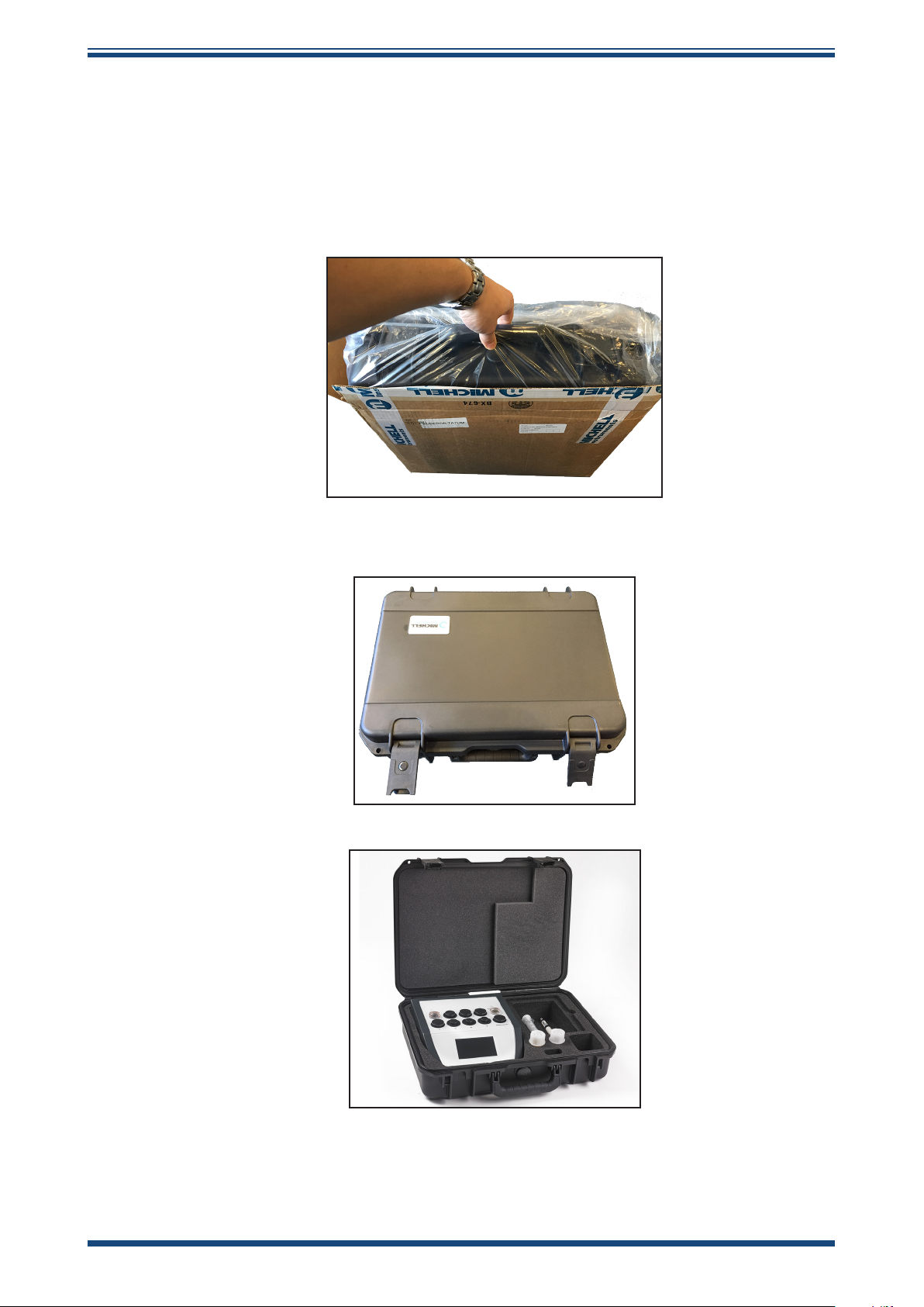
2.1 Unpacking
Open the box and unpack carefully as follows
1. Remove the carry case from the packing box.
HygroCal100 User’s Manual
2. Open the carry case.
3. Remove the instrument and place on a level surface.
Save all the packing materials for the purpose of returning the instrument for recalibration
or any warranty claims.
2 97500 Issue 1, September 2015
Page 11

HygroCal100 User’s Manual
The carry case should contain the following items:
• Control sensor calibration certicate
• Power adaptor
• User manual
• Port adaptor tool
• Spare Port adaptors (optional)
• Desiccant and water bottles (optional)
If there are any shortages please notify Michell Instruments immediately.
If Calibration Kit 1 or 2 has been ordered, then a separate box will also be supplied
containing the reference instrument (either an MDM25 or Optidew Vision). The specic
port adaptors for the reference will be in the carry case with any other spare port
adaptors ordered.
INSTALLATION
2.2 Operating Requirements
2.2.1 Environmental Requirements
It is important to operate the HygroCal100 within the following environmental conditions:
Minimum operating temperature +5°C (+41°F)
Maximum operating temperature +40°C (+104°F)
Maximum relative humidity 95%
2.2.2 Electrical Requirements
The power adaptor for the HygroCal100 requires the following electrical supply:
100 to 240 V AC, 50/60 Hz
Michell Instruments 3
Page 12

INSTALLATION
2.3 Exterior Layout
The controls, indicators and connectors associated with the HygroCal100 are located on
the front, top and rear panels of the device.
Front Panel
HygroCal100 User’s Manual
1 2
1 USB port
2 Touch screen display
Figure 1
Accepts a USB memory device for the transfer of logged
data (see Section 3.4.4.4 for instructions on how to
download logged data).
Displays measured readings and enables the user to
control the operation of the chamber.
Front Panel
4 97500 Issue 1, September 2015
Page 13
HygroCal100 User’s Manual
Top Panel
INSTALLATION
1
3
2
1 Saturator reservoir
2 Probe ports
3 Desiccant reservoir
Figure 2
Contains a diffuser and distilled water used to humidify the
air in the chamber (see Section 4.2 for instructions on how
to rell the saturator).
Used to mount probes under test into the chamber (see
Section 2.5.1 for instructions on how to install port adaptors
and probes).
Contains desiccant used to dry the air in the chamber (see
Section 4.1 for instructions on how to replace desiccant).
Top Panel
Michell Instruments 5
Page 14
INSTALLATION
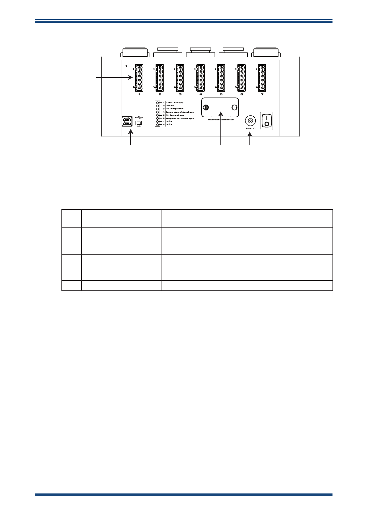
Rear Panel
1
HygroCal100 User’s Manual
42 3
Figure 3
1 Probe input connections
USB communications
2
port
3 Service access port
4 Power adaptor input 24 V DC input.
Connections for probes under test (see Section 2.5.1 for
instructions on how to connect probes).
Allows the HygroCal to be connected to a PC, outputting
the relative humidity and temperature values of both the
reference probes and the probes under test.
Remove for replacement of HS3 control probe (see
Section 4.3 for instructions on how to replace the control
probe).
Rear Panel
6 97500 Issue 1, September 2015
Page 15
HygroCal100 User’s Manual
!
2.4 Rear Panel Layout
These tasks should only be undertaken by qualied personnel.
Connections to the rear panel of the chamber are explained in the following sections:
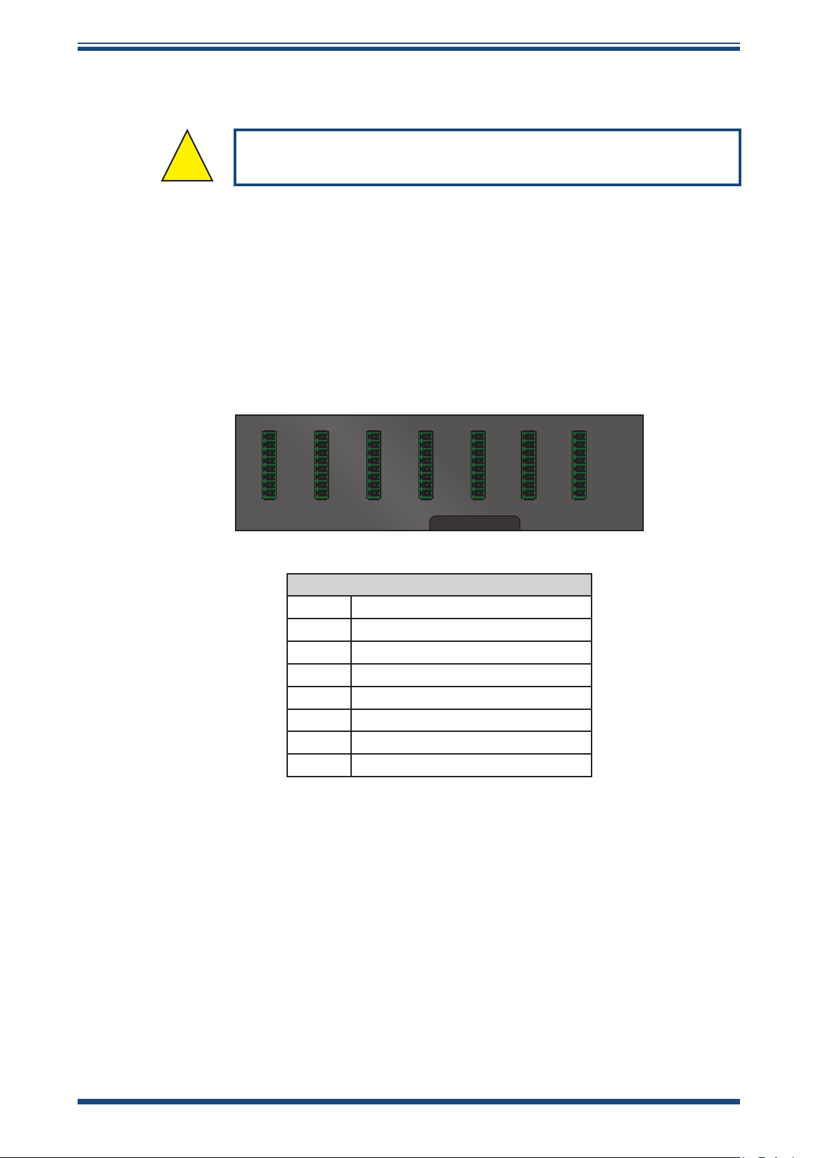
2.4.1 Probe Input Connections
Seven 8-pin connectors are provided to allow connection of probes under test. Probes
with a voltage or current input can be connected.
INSTALLATION
1 2 3 4 5 6 7
Probe Input Connector Pins
1 +24 V DC supply
2 Ground
3 RH voltage input
4 Temperature voltage input
5 RH current input
6 Temperature current input
7 Not connected
8 Not connected
Figure 4
Probe Input Connections
Michell Instruments 7
Page 16
INSTALLATION
1 2 3 4 5 6 7
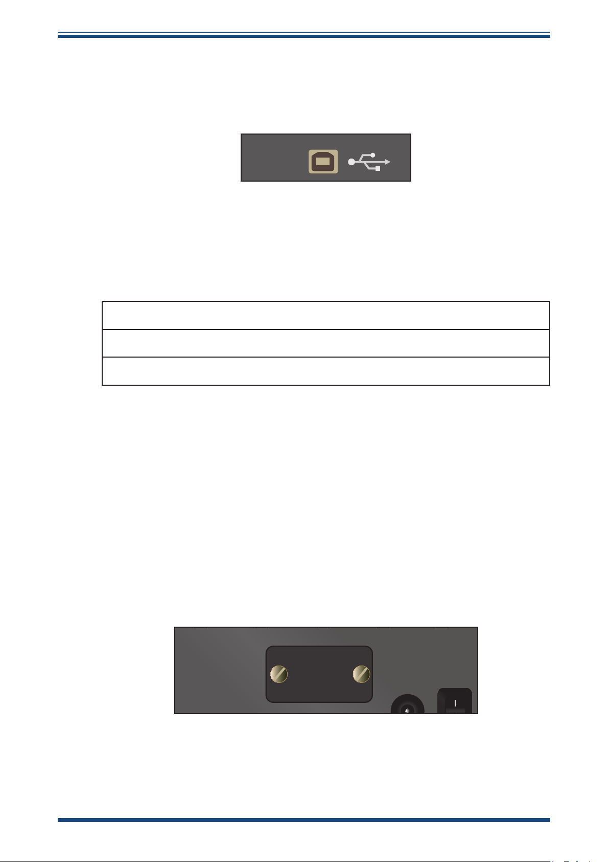
2.4.2 USB Communications Port
The USB type-B connector on the rear panel allows the HygroCal to be connected to
a PC, outputting the relative humidity and temperature values of both the reference
probes and the probes under test.
HygroCal100 User’s Manual
Figure 5
When connecting the port to a PC, the device will be installed as a virtual serial port,
and assigned its own COM port number, allowing communication with many different
engineering programs and programming languages.
The output will be in the following format:
InternalReferenceRH Probe1RH Probe2RH Probe3RH Probe4RH Probe5RH Probe6RH Probe7RH
InternalReferenceTP Probe1TP Probe2TP Probe3TP Probe4TP Probe5TP Probe6TP Probe7TP
0100 0114 FFFF 0115 FFFF FFFF FFFF FFFF 00E9 00E4 FFFF 00E3 FFFF FFFF FFFF FFFF
Each 2 byte hex word is a 16 bit unsigned integer, which should be divided by 10 to give
the actual decimal value of the associated reading.
e.g. Internal Reference RH value 0x0100 = 256. Dividing this value by 10 gives the
%RH value 25.6%
USB Communications Port
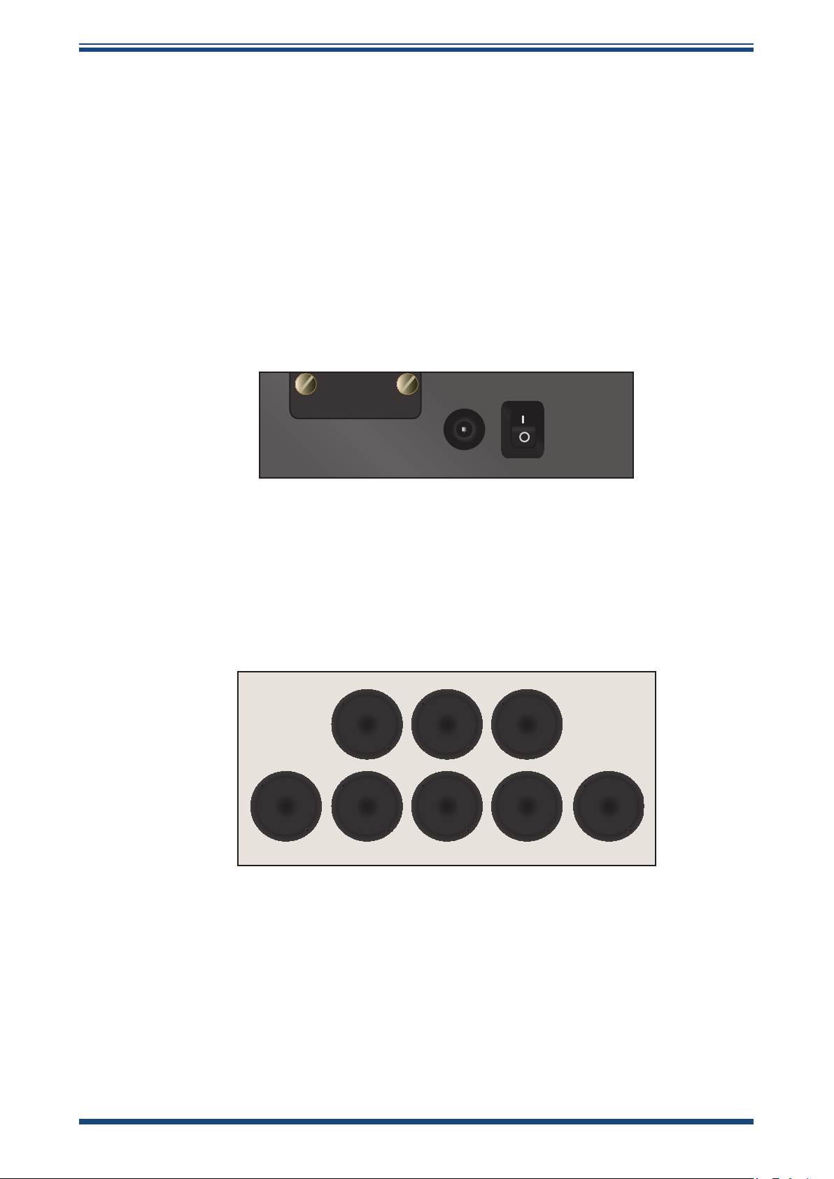
2.4.3 Service Access Port
The service access port has a cover which can be removed to access the HS3 control
sensor for replacement (see replacement instructions in Section 4.3).
The cover is held in place by two at-head screws.
Figure 6
Service Access Port
8 97500 Issue 1, September 2015
Page 17
HygroCal100 User’s Manual
2.4.4 Power Adaptor Input
The DC power connector is a push t into the power input socket, as shown in gure X.
The method of connection is as follows:
1. Ensure that both ends of the power cable are potential free, i.e. not
connected to an AC power supply.
2. Check that the ON/OFF switch is switched to OFF.
3. Push the connector into the power input socket.
4. Connect the mains plug of the power adaptor to a suitable AC power
source (voltage range 100 to 240 V AC, 50/60 Hz) and switch on the AC
supply.
5. Switch on the instrument, as required, using the power ON switch.
INSTALLATION
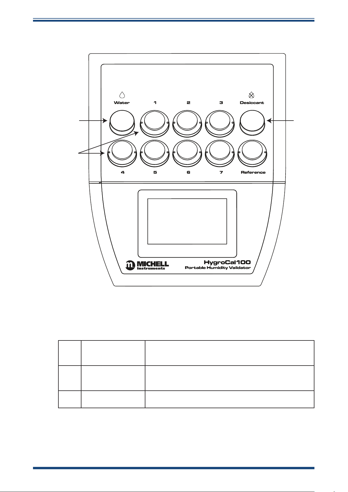
2.5 Top Panel Layout
2.5.1 Probe Ports
Seven ports are provided for the installation of probes under test. Each port is tted
with an adaptor, which allows the probe to be sealed into the chamber by means of an
O-ring.
Figure 7
24V DC
Power Adaptor Input
Figure 8
Adaptors are available with a wide variety of port sizes, from 12 to 25mm.
To install a port adaptor, locate the port adaptor removal tool (A000265) in the pin holes
on each adaptor, and unscrew or tighten the adaptor into the port. Take care not to
crossthread the adaptors.
To install a probe, simply t the correct size of port adaptor, remove the blanking plug,
and push the probe straight through the center of the adaptor until the O-ring grips the
probe shaft at its widest point. Ensure that any ports not in use are blanked off with
the appropriate plug.
Probe Ports
Michell Instruments 9
Page 18

INSTALLATION
2.5.2 Desiccant Reservoir
HygroCal100 User’s Manual
DESICCANT
The desiccant reservoir should be lled with the desiccant provided before operation:
1. Remove the lid.
2. Pour in fresh desiccant until full to inside lip.
3. Re-t the lid.
The desiccant chamber requires 25cm3 of desiccant to ll, which is approximately
equivalent to lling up to the inside lip.
2.5.3 Saturator Reservoir
Figure 9
Desiccant Reservoir
WATER
Figure 10
Saturator Reservoir
The saturator provides the source of humid air for the chamber.
Distilled water should be added to the saturator before operation:
1. Remove the lid.
2. Pour in 25ml distilled water.
3. Re-t the lid.
The saturator should only be lled with distilled water - no more than 25ml total (refer
to Section 4.2).
NOTE: Always remove water from the saturator reservoir before transportation.
10 97500 Issue 1, September 2015
Page 19

HygroCal100 User’s Manual
11:00
3 OPERATION
Once lled with water and desiccant, the HygroCal100 is ready for operation. This
section describes both the general operation of the chamber and the method of setting
it up and changing the default parameters (see Section 3.4.5.4) should this become
necessary.
3.1 General Operational Information
The chamber should be placed on a level surface in an environment with as stable an
ambient temperature as possible. When moving the device from one place to another
leave for 30 minutes to 1 hour in the new location to allow the temperature of the
HygroCal100 to equilibrate with the prevailing ambient.
The HygroCal100 is suitable for verifying almost any relative humidity sensor, provided
that it can be tightly sealed into the chamber.
OPERATION
3.2 Display
The HygroCal100 features a 4.3" colour touch screen display.
When the chamber is switched on the screen will initially be blank while the menu
system loads.
After the menu system has loaded, the Main Screen will show.
Set Point
Internal Reference Humidity
50.2
Humidity
Temperature
Probe 3
50.0%
20.8
°C%RH
100
0
0 30Minutes
Chamber:
Mode:
Next Point:
Stable
Auto
00:01:33
Temperature
52.0
%RH
22.3
°C
Figure 11
CALIBRATION
SETTINGS
Main Screen
SYSTEM
SETTINGS
TABLE VIEW
Michell Instruments 11
Page 20

OPERATION
3.3 Main Screen Layout
1
% RH SET POINT
REFERENCE READOUT
2
PROBE SELECTION
3
PROBE READOUT
4
6
7 8 9
CALIBRATION
SETTINGS
HygroCal100 User’s Manual
STABILITY GRAPH
5
OPERATIONAL STATUS
DISPLAY
SYSTEM
SETTINGS
TABLE VIEW
1 Relative Humidity Set Point
2 Reference Readout
3 Probe Selection
4 Probe Readout
5 Stability Graph
6 Operational Status Display
7 Calibration Settings Button
8 System Settings Button
9 Table View Button
Figure 12
Main Screen Layout
Indicates the target RH set point. See Section 3.4.1
for additional information.
Displays the RH and temperature readouts of the
selected reference sensor.
Switches between the currently connected probes.
See Section 3.4.2 for additional information.
Displays the RH and temperature readouts of the
selected probe.
Displays a plot of RH over time. Touch and hold the
readout to enter full screen mode.
A detailed description of each item displayed in this
area is in Section 3.4.3.
Access to the Calibration Settings Menu. See Section
3.4.4 for more information about the Calibration
Settings menu.
Access to the System Settings Menu. See Section
3.4.5 for more information about the System
Settings menu.
Access to the Table View Screen. See Section 3.4.6
for more information about Table View.
12 97500 Issue 1, September 2015
Page 21

HygroCal100 User’s Manual
3.4 Menu Structure
Mode Probes Program Logging Ref Setup
OPERATION
Cal Settings
Operation
Mode
Output Signal RH Status
Temp. Zero Duration Filename
Temp. Span Interval
Log Files
System Settings
Displayed
Reference
Port
Selection
External
Input
External
Temperature
Zero
External
Temperature
Span
Display Clock About Correct
Primary Unit Day
Language Month
Brightness
Year
Hour
Minute
Password
Calibration
Points
Transfer
Michell Instruments 13
Page 22

MAINTENANCE
11:00
3.4.1 Current Set Point
The target relative humidity level can be changed by pressing the Set Point pane in the
top left of the main screen. This is only possible when Calibration Settings -> Mode is
set to Manual.
HygroCal100 User’s Manual
Set Point
3.4.2 Probe Selection
The probe selection pane on the Main Screen can be congured to show the relative
humidity and temperature readings of any of the connected probes.
7
4
1
0
Figure 13
70.0%
8
5
2
9
C
6
3
.
Set Point Entry Screen
To cycle through the connected probes, touch the left or right arrow keys on either side
of the probe number indication.
3.4.3 Operational Status Display
The Operational Status Display includes the following:
Chamber
Mode
Next Point
Indicates the operational condition of the chamber.
Options: RESPONDING, STABILIZING, STABLE or OFF
Indicates the operating mode of the chamber.
Options: MANUAL, AUTO or STANDBY
When the conditions in the chamber are stable this will indicate the
time remaining until the next set point.
14 97500 Issue 1, September 2015
Page 23

HygroCal100 User’s Manual
13:00
LOGGING
MODE
PROBES
REF SETUP
PROGRAM
12:09
3.4.4 Calibration Settings
The Calibration Settings Screen is used to congure the probes under test, the calibration
routine to be followed and the data logging feature.
Initially, when the Calibration Settings Screen is opened, a set of labelled icons is
displayed. Touching once of these icons will take you to the appropriate submenu.
Calibration Settings
CALIBRATION
3.4.4.1 Mode
Figure 14
Operation Mode
Operation Mode
Figure 15
Calibration Settings Screen
Auto
Operation Mode Screen
Parameter Description
Determines whether the chamber is controlling manually according
Operation Mode
to the target set point on the Main Screen, automatically according
to an entered calibration routine, or remaining in standby mode.
Available Input: Manual/Auto/Standby
Table 1 Operation Mode Screen Parameters
Michell Instruments 15
Page 24

OPERATION
11:46
3.4.4.2 Probes
HygroCal100 User’s Manual
Probes
Probe 1
Output Signal Temp. Zero
Figure 16
Parameter Description
Probe # Scrolls through the probe ports using the left and right arrows
Output Signal
Temp. Zero
Temp. Span
The output signal used by the probe currently selected
Available Input: 0-20 mA, 4-20 mA, 0-1 V, 0-5 V, 0-10 V
For this probe # - Sets the temperature which corresponds to a zero
output
Available Input: Numerical
For this probe # - Sets the probe temperature which corresponds
to a span output
Available Input: Numerical
0-1V -40.0
Temp. Span
60.0
Probe Setup Screen
Table 2 Probe Setup Screen Parameters
16 97500 Issue 1, September 2015
Page 25

HygroCal100 User’s Manual
11:46
3.4.4.3 Program
Program
Calibration Routine
Point
1
RH
(%)
30.0 00:15
Duration
(hh:mm)
OPERATION
2
3
4
5
Figure 17
35.0 00:20
40.0 00:30
45.0 00:40
50.0 00:45
Program Calibration Routine Screen
START
The table provided in the Calibration Routine Screen allows a series of relative humidity
points to be generated for set time periods without intervention by the user.
Each row of the table denes a calibration point, with elds to enter the desired relative
humidity value and the length of time the chamber should spend maintaining this
humidity.
Once this period of time has elapsed, the chamber will move to the conditions on the
next row. There can be a maximum of 10 calibration points in the routine.
NOTE: The 'Duration' only starts when the chamber has stabilized at the
desired condition.
To initiate the calibration routine, touch the Start button.
At this point, if logging is not in progress, then a prompt will appear to conrm whether
or not logging is required.
If NO is selected, then the program will start and the display will return to the Main
Screen.
If YES is selected, then the Logging Screen will be displayed. Once data logging has
been initiated the program will run.
Michell Instruments 17
Page 26

OPERATION
11:47
3.4.4.4 Logging
HygroCal100 User’s Manual
Logging
Status
Filename
Interval
(mm:ss)
Figure 18
Parameter Description
Status
Filename
Interval
Shows whether logging is active or not.
Available Inputs: None
Sets the name for the next log le.
Available Input: Text
Sets the frequency at which logged data will be collected.
Available Inputs: Time in minutes and seconds
Not Logging
HYGROCAL
00:01
LOG FILES
HygroCal100 Logging Screen
START
Table 3 HygroCal100 Logging Screen Parameters
Once a lename has been set, logging can be initiated by touching the Start button.
The Log Files Screen can also be accessed from here.
18 97500 Issue 1, September 2015
Page 27

HygroCal100 User’s Manual
15:59
Log les
Log Files
OPERATION
File
1
2
3
4
5
Memory usage: 15 / 1965 MB
Name Date
HYGR(31) 25-02-2016
HYGR(30) 25-02-2016
HYGR(29) 25-02-2016
HYGR(28) 25-02-2016
HYGR(27) 25-02-2016
Figure 19
Log Files Screen
DELETE
X
ALL
TRANSFER
X
SELECTED
This screen allows management of the log les currently stored on the HygroCal100.
Each of the log les is listed as its own row in this screen, the rows are scrollable by
means of the up and down arrows located on the left-hand side. The rows also have tick
boxes, which can be used to highlight each independently.
Once a row has been highlighted, it can be either transferred to USB memory or deleted.
Alternatively the Delete: All key can be used to wipe all logged data from the device.
Michell Instruments 19
Page 28

OPERATION
11:48
3.4.4.5 Reference Setup
RH Reference Setup
HygroCal100 User’s Manual
Displayed Reference
Port Selection
External Input
External Temperature Zero
External Temperature Span
Figure 20
External
1
0-1V
-40.0
60.0
RH Reference Setup Screen
Parameter Description
Displayed
Reference
Chooses to display the readings of either the internal control sensor
or an external device as the reference.
Available Input: Internal, External
Port Selection Selects the probe port if the external reference is connected.
External Input
External
Temperature
Zero
External
Temperature
Span
Selects the output signal if the external reference is connected.
Available Input: 0-1V, 0-5V, 0-10V, 0-20mA, 4-20mA
Sets the temperature which corresponds to a zero output if the
external reference is connected.
Available Input: Numerical
Sets the temperature which corresponds to a span output if the
external reference is connected.
Available Input: Numerical
Table 4 RH Reference Setup Screen Parameters
20 97500 Issue 1, September 2015
Page 29

HygroCal100 User’s Manual
11:55
11:49
3.4.5 System Settings
System Settings
DISPLAY CLOCK ABOUT CORRECT
OPERATION
Used to congure the internal parameters of the HygroCal100, and to access the internal
calibration correction functionality.
3.4.5.1 Display
Figure 21
Display Settings
Primary Unit
Language
Brightness
System Settings Screen
°C
English
6
Figure 22
Display Settings Screen
Parameter Description
Primary Unit
Changes the primary temperature unit.
Available inputs: °C, °F
Changes the display language.
Language
Available inputs: English, French, German, Spanish, Portuguese,
Italian
Brightness
Alters display brightness.
Available Inputs: 0-6
Table 5 Display Settings Screen Parameters
Michell Instruments 21
Page 30

OPERATION
10:55
3.4.5.2 Clock
HygroCal100 User’s Manual
Clock
Day Month
Date
Time
03 09
Hour Minute
11 49
Figure 23
Parameter Description
Day
Month
Year
Hour
Minute
Current Day.
Available Inputs: DD
Current Month.
Available Inputs: MM
Current Year.
Available Inputs: YYYY
Current Hour.
Available Inputs: HH
Current Minute.
Available Inputs: MM
Year
2015
Clock Settings Screen
Table 6 Clock Settings Screen Parameters
22 97500 Issue 1, September 2015
Page 31

HygroCal100 User’s Manual
10:55
13:04
3.4.5.3 About
About
OPERATION
Displays Firmware version, and date of last internal calibration correction.
3.4.5.4 Correct
Firmware Version
Last Calibration Date
© Copyright Michell Instruments B.V.
Figure 24
Calibration Correction
1.1.4
24-02-2015
About Screen
- Check saturator
- Check desiccant
- Is external reference installed?
Calibration Points
Figure 25
Calibration Correction Screen
TRANSFERTEMP
APPLYDEFAULT
In order to enter the Calibration Correction Screen, a prompt box will appear asking the
user to enter a code. To proceed, enter 7316.
The Calibration Correction Screen allows the initialization of an internal calibration
routine. The number of calibration points can be changed between 3, 5 and 9.
The data collected from previous calibrations can be transferred to installed USB memory
by means of the Transfer button.
The calibration correction can be reset to the default factory values, by means of the
Default button.
Michell Instruments 23
Page 32

OPERATION
12:40
Once started, the calibration procedure continues automatically, pausing once each
point is complete to request conrmation to continue. As the calibration progresses,
a table of the results collected will be displayed, along with the time remaining at the
current point - see below.
HygroCal100 User’s Manual
Calibration Correction
Set Point Int. Reference Ext. Reference Time
30.0
50.0
70.0
29.9
49.9
70.0
30.9
51.2
70.3
00 : 00
APPLY
Once all the requested calibration points have been completed, the Apply button will
appear, to conrm and complete the correction process.
At any point the calibration can be cancelled by touching the Exit icon.
3.4.6 Table View
Table view allows the readings of the designated reference and all probes under test to
be viewed simultaneously.
Figure 26
Calibration in Progress Screen
24 97500 Issue 1, September 2015
Page 33

HygroCal100 User’s Manual
3.5 Port Adaptors
The HygroCal100 is tted with 8 M30 probe test ports. Each of these is tted with an
adaptor to convert it to one of a variety of probe tube diameter sizes.
OPERATION
Figure 27
The HygroCal100 is supplied with your choice of port adaptor size - additional adaptors
can be ordered.
Port adaptors suitable for the following probe sizes are available:
Probe Diameter Order Code
12mm A000291
13.5mm A000292
14mm A000293
15mm A000294
18.5mm A000295
19mm A000296
24mm A000297
25mm A000298
Adaptors can be installed or removed using the Port Adaptor Tool (A000265). Take care
to ensure that the port adaptor is properly aligned with the thread before tightening.
Port Adaptor
Figure 28
Port Adaptor Tool
3.6 Probe Installation
3.6.1 Chamber Connection
To install a probe into the HygroCal100 chamber, rstly ensure that you have the correct
port adaptor size for the diameter of the probe.
1. Remove the blanking plug from the port adaptor and keep it safe.
2. Install the probe into the port adaptor - ensure that the probe is inserted
as far as possible into the chamber as is possible while maintaining a
good seal to the sensor body tube.
Michell Instruments 25
Page 34

OPERATION
3.6.2 Electrical Connection
Seven push t connector blocks are provided on the rear panel to allow power to and
communications with the probes under test.
Each connector has 6 active pins, which can be used with 3 or 4-wire probes which have
either a voltage or current output, depending on how it is wired.
Pin Function Description
1 +24 V DC supply Excitation voltage for probe
2 Ground Ground
HygroCal100 User’s Manual
3 RH voltage input
4 Temperature voltage input
5 RH current input
6 Temperature current input
7 N/C Not connected
8 N/C Not connected
NOTE: This table also appears on the rear panel of the instrument for quick
reference.
For each connection:
1. Remove the terminal block.
RH input connection for probes with a
voltage scale output
Temperature input connection for probes
with a voltage scale output
RH input connection for probes with a
current scale output
Temperature input connection for probes
with a current scale output
2. Strip back the wires on the probe lead to ensure at least 6mm is exposed
(if necessary).
3. Insert the wire for the ground connection into the Ground terminal way,
and screw into the block. NOTE: Do not overtighten the screw.
4. Insert the wire for the supply connection into the +24 V DC terminal way,
and screw into the block. NOTE: Do not overtighten the screw.
5. Insert the wire for the RH signal connection into either the RH voltage
input or RH current input terminal way - depending on the probe - and
screw into the block. NOTE: Do not overtighten the screw.
6. Insert the wire for the temperature signal connection (if present) into
either the Temperature Voltage Input or Temperature Current Input
terminal way - depending on the probe - and screw into the block. NOTE:
Do not overtighten the screw.
7. Locate the terminal block over the connector and push it rmly into place.
26 97500 Issue 1, September 2015
Page 35

HygroCal100 User’s Manual
11:00
3.7 Battery Operation
The HygroCal100 is tted with a battery pack, allowing it to be used without the DC
power supply connected.
The HygroCal100 can run from a fully charged battery for approximately 8 hours
(depending on set point).
The battery pack will power the instrument automatically when the DC supply is
disconnected.
3.8 Operating Guide
3.8.1 Manual Mode
When the Operating Mode is set to Manual, the chamber will continually generate the
currently selected set point. The set point is determined by touching the 'set point'
indication on the Main Screen, which brings up a window allowing the desired value to
be entered.
OPERATION
Set Point
7
4
1
0
Figure 29
70.0%
8
5
2
9
C
6
3
.
Set Point Entry Screen
Michell Instruments 27
Page 36

OPERATION
11:46
3.8.2 Automatic Mode
In order to program a calibration routine to run automatically, the operating mode
should rst be set to Auto from the Calibration Settings Screen -> Mode.
A calibration routine can then be dened, through the Calibration Settings Screen ->
Program. Each point in the calibration is listed by row. Touching the up or down arrows
on the left of the list will scroll through the 10 points which can be assigned.
Each row contains a relative humidity value in %, and a duration in the format HH:MM.
For each row, the target relative humidity value will be maintained for the duration.
NOTE: The duration does not include time taken to reach and stabilize on the
target. Consider the example calibration routine in
the chart in
Figure 31
Program
HygroCal100 User’s Manual
Figure 30,
.
and its visualization in
100.00
90.00
80.00
70.00
60.00
Calibration Routine
Point
1
2
3
4
5
Figure 30
RH
(%)
30.0 00:04
35.0 00:05
40.0 00:21
45.0 00:22
50.0 00:23
Example of Calibration Routine
Duration
(hh:mm)
START
Stabilization Time
Duration
Actual %RH
Set Point
50.00
40.00
30.00
20.00
10.00
0.00
00.00
00.04
00.08
00:12
00:16
00:20
00:24
00:28
00:32
00:36
00:40
00:44
00:48
00:52
00:56
01:00
01:04
01:08
01:12
01:16
01:20
01:24
01:28
01:32
01:36
01:40
01:44
01:48
01:52
01:56
02:00
02:04
02:08
02:12
02:16
02:20
02:24
02:28
02:32
Figure 31
Visualization of Calibration Routine
28 97500 Issue 1, September 2015
Page 37

HygroCal100 User’s Manual
The time taken for the chamber to respond to the set point is shown in red ll - this is
not included in the duration for that set point, which is shown in blue ll.
When the step change in humidity is large, the chamber will take longer to reach the set
point. It will typically take much longer to dehumidify than to humidify, so the transition
from 30% to 50% will be quicker than 50% to 30%.
3.9 Operating Practice
To perform a reliable humidity validation, it is important to follow these basic guidelines:
When starting a validation routine, ensure that the temperature of the environment
you intend to operate in is stable, and that the HygroCal100 has been in the stable
environment for enough time to reach temperature equilibrium with its surroundings.
If the HygroCal100 is not allowed time to stabilize with its environment, then the
conditions that each probe under test experiences may not be the same. Due to the
key inuence temperature has on determining relative humidity, validation errors would
result.
OPERATION
For example, at an ambient of 23°C and a set point of 40%RH, a difference of 0.5°C
could affect the RH by up to 1.25%. At lower humidities the difference can be even
more signicant.
When running a validation routine, it is usually advisable to start with the driest points
rst and increase the humidity.
There are several benets to this:
• Speed of transition - it is much quicker for the chamber to add humidity
than to remove it, therefore a validation running from dry to wet will
require shorter transition and stabilization times than one running from
wet to dry.
• Service life of desiccant - repeatedly asking the chamber to dehumidify
will result in a much shorter desiccant lifetime than if the cycle is run so
that humidity only needs to be added.
Always ensure, when installing probes into the chamber, that the port adaptor used is
of the correct diameter for the probe body, so that there are no potential leak points.
Michell Instruments 29
Page 38

MAINTENANCE
3.9.1 Humidity Stabilization Times
The time taken for the HygroCal chamber to stabilize after a transition will depend on
a number of factors:
• Magnitude of the humidity change
• Direction of the humidity change
• Temperature of the operating environment
To take an extreme example, expect that for complete stability at 95% RH from a
starting point of 5%, 35 minutes should be allowed.
For smaller transitions, shorter timescales can be expected. Typically for a step change
<Δ50%, stability can be reached within 15 minutes.
3.9.2 Data Logging
HygroCal100 User’s Manual
The logging function, when active, will continually capture the the target set point in
addition to the readings of the internal reference and all probes under test. This will be
written to the internal memory as a CSV le.
The les are identied both by number and by the name assigned as the log is initiated.
The Log Files Screen allows multiple les to be selected and downloaded.
3.10 Standby Mode
Standby mode can be activated through the Calibration Settings Screen -> Mode (see
Section 3.4.4.1). When it is active the pump will shut off and the unit will not control
the chamber condition.
3.11 External Reference Conguration
It is possible to dene one of the devices connected into the chamber as an external
reference. The readings of this device will be displayed as the reference readings on the
Main Screen. However, the internal reference will still be used to control the chamber.
When choosing an external reference, the port to which it is connected must be selected.
The range and input settings which were previously set for this port will be loaded, but
elds to change them can be found on the Calibration Settings Screen -> Ref Setup
(see Section 3.4.4.5).
An external reference must be connected in order to carry out a calibration correction
of the internal reference.
30 97500 Issue 1, September 2015
Page 39

HygroCal100 User’s Manual
4 MAINTENANCE
4.1 Desiccant Reservoir
The desiccant reservoir should be lled up to the inside lip - this will require approximately
25cm3 of desiccant.
When fresh, the desiccant will be orange, as shown below:
MAINTENANCE
As it becomes exhausted, it will lose its color and become clear.
To replace the desiccant, it is preferable to empty the chamber by use of a vacuum
cleaner.
The desiccant can be regenerated by emptying it completely from the desiccant chamber
and drying it in an oven for approximately 3 hours at a temperature between 130°C
(266°F) and 160°C (320°F). After drying it in an oven, allow the silica gel to cool before
relling the desiccant chamber.
Alternatively spare desiccant can be ordered in two different package sizes:
Quantity Order Code
250g A000171
3kg A000172
Michell Instruments 31
Page 40

MAINTENANCE
4.2 Saturator Reservoir
The saturator should be be lled with 25ml of distilled water. The water level in the
saturator will reduce over time as it is consumed in the process of humidifying the
chamber.
NOTE: Always remove water from the saturator reservoir before transportation.
4.3 Replacing the Internal Reference Sensor
The internal reference is a Michell Instruments HygroSmart 3 control sensor.
A replacement can be ordered from your local Michell Instruments representative, using
the part number: HS3-S-B1.
HygroCal100 User’s Manual
To replace the sensor:
1. Loosen the two screws securing the service panel to the rear of the unit.
2. The reference sensor is attached to the service panel, and sealed into the
control chamber by an O-ring. Gently pull the panel away, removing the
HS3 control sensor from the chamber.
3. Unscrew the collar at the base of the HS3, then pull the HS3 away from
the connector which attaches it to the service panel.
4. The replacement control sensor can then be installed in its place.
32 97500 Issue 1, September 2015
Page 41

HygroCal100 User’s Manual
13:04
4.4 Calibration Correction
The HygroCal100 is provided with an intuitive calibration correction system which is used
to calibrate and adjust the internal HS3 control sensor against an external reference
device.
If a traceable reference is available, it is advisable to pass the traceability of this onto
the control sensor of the HygroCal100 at regular intervals. The process allows calibration
at 3, 5 or 9 preset points, which are:
MAINTENANCE
Preset RH Points
Total time to
complete
3 point 30%, 50%, 70% 45mins
5 point 20%, 30%, 50%, 70%, 80% 1hr 15mins
9 point 10%, 20%, 30%, 40%, 50%, 60%, 70%, 80%, 90% 2hr 15mins
Select System Settings -> Correct. This will display a prompt to enter a password
to proceed - the required code is 7316. Once this has been entered, the Calibration
Correction Setup Screen will be displayed. This screen shows a number of checks which
should be carried out before proceeding.
NOTE: If the desiccant is exhausted, or the saturator is not sufciently lled,
then this can result in an invalid correction being applied to the control sensor.
NOTE: Ensure that the temperature of the environment you intend to operate
in is stable before proceeding.
Calibration Correction
- Check saturator
- Check desiccant
- Is external reference installed?
Calibration Points
Figure 32
3
DEFAULT
Calibration Correction Setup Screen
TRANSFERTEMP
START
The Calibration Correction Setup Screen allows selection of the desired number
of calibration points. Once this choice is made, touch the Start button to begin the
calibration.
Previous calibration corrections can be downloaded to USB memory by touching the
Transfer icon, and will be stored in CSV format as per the log data les (see Section
3.9.2 for further information).
Michell Instruments 33
Page 42

MAINTENANCE
12:13
Install and congure an authoritative external reference instrument before proceeding. If
this is not done, then the External Reference Setup Screen will be displayed. Proceeding
from here will begin the calibration correction routine.
HygroCal100 User’s Manual
Calibration Correction
Set Point Int. Reference Ext. Reference Time
30.0
50.0
70.0
30.9
0.0
0.0
32.1
0.0
0.0
14 : 56
Figure 33
The Calibration Correction Screen will then be displayed, and the chamber set point will
be changed to the rst point in the routine. After 15 minutes, the values read by both
the sensor and reference will be sampled to determine the required correction. An icon
labelled next will appear in the bottom right of the screen - touch this to conrm and
continue to the next point.
After all points are complete, the Apply button will appear. Pressing this will apply the
table and complete the calibration.
At any point during the process, touching the Exit icon will abandon the current
calibration.
Calibration Correction Screen
34 97500 Issue 1, September 2015
Page 43

HygroCal100 User’s Manual
APPENDIX A
Appendix A
Technical Specications
Michell Instruments 35
Page 44

APPENDIX A
HygroCal100 User’s Manual
Appendix A Technical Specications
Chamber
Generation Range 5 to 95% RH
RH Stability ±0.5%
RH Uniformity ±0.5%
Stabilization Time Typically <5 min for full stability from step changes of 10% RH
Control Probe
Accuracy ±0.8%
Long Term Stability ±1% per year
Electrical Specication
User Interface 4.3" color LCD with touchscreen
Measurement Units %RH, temperature in °C, °F
Displayed Resolution 0.1
Data Logging
Battery 1500 mAh
Power Supply 24 V DC (100 to 240 V AC, 50/60 Hz adaptor included)
2Gb internal memory available for log les; or 10.6 years storage
at 5 second intervals
Mechanical Specication
Probe Ports
Chamber Volume 1050cm3 approximately
Maximum Probe Insertion Depth 60mm (2.36")
Desiccant Reservoir Capacity 25cm
Saturator Reservoir Capacity 25ml
Environmental Conditions +5 to +40°C (+41 to +104°F)
Dimensions 100 x 250 x 300mm (3.94 x 9.84 x 11.81") h x w x d
Weight 3.2kg (7.05lbs)
8 - sensor body diameters 5 to 25mm, accommodated by port
adaptors
3
36 97500 Issue 1, September 2015
Page 45

HygroCal100 User’s Manual
APPENDIX B
Appendix B
Troubleshooting
Michell Instruments 37
Page 46

APPENDIX B
Appendix B Troubleshooting
Problem Possible Solution
Not drying or drying slowly Change desiccant
Water in chamber Dry chamber
Not humidifying or humidifying slowly Water level too low
HygroCal100 User’s Manual
38 97500 Issue 1, September 2015
Page 47

HygroCal100 User’s Manual
APPENDIX C
Appendix C
EU Declaration of Conformity
Michell Instruments 39
Page 48

APPENDIX C
2004/108/EC
EMC Directive
Appendix C EU Declaration of Conformity
HygroCal100 User’s Manual
EU
Declaration of Conformity
Manufacturer: Michell Instruments BV
Krombraak 11
4906 CR Oosterhout
The Netherlands
We declare under our sole responsibility that the product:
HygroCal100
complies with all the essential requirements of the EU directives listed below.
and has been designed to be in conformance with the relevant sections of the following standards or
other normative documents.
EN61326-1:2013
Electrical equipment for measurement, control and laboratory
use – EMC requirements –Class B (emissions) and Industrial
Locations (immunity).
Peter Haakma, Managing Director
Date of Issue: June/2015
40 97500 Issue 1, September 2015
Page 49

HygroCal100 User’s Manual
APPENDIX D
Appendix D
Quality, Recycling
& Warranty
Information
Michell Instruments 41
Page 50

APPENDIX D
HygroCal100 User’s Manual
Appendix D Quality, Recycling & Warranty Information
D.1 Pressure Equipment Directive (PED) 97/23/EC
The above Directive has been implemented in United Kingdom Law by the Pressure Equipment
Regulations 1999.
The Regulations require that all pressure equipment and assemblies within the scope of the Pressure
Equipment Directive must be safe when placed on the market or put into service.
Michell Instruments’ products have been assessed and, as referenced against the Classication Charts
detailed in Annex II of the Directive, do not fall into the requirements for CE marking compliance
with the Pressure Equipment Directive.
Article 3, paragraph 3 states that any product containing a pressurized uid that does not qualify for
compliance should, nevertheless, be constructed with Sound Engineering Practice (SEP).
Michell Instruments attests here that its products have been designed, manufactured & tested to
assure safe operation, and in accordance with Sound Engineering Practices.
D.2 Recycling Policy
Michell Instruments is concerned with the protection of the environment. It is our commitment to
reduce and eliminate from our operations, wherever possible, the use of substances which may be
harmful to the environment. Similarly, we are increasingly using recyclable and/or recycled material
in our business and products wherever it is practical to do so.
To protect natural resources and to promote material reuse, please separate batteries from other
types of waste and recycle responsibly. If batteries are not properly disposed of, these substances
can cause harm to human health and the environment
The product that you have purchased may contain recyclable and/or recycled parts and we will be
happy to provide you with information on these components if required. For further information
please see the following sections.
D.3 WEEE Compliance
Directive 2012/19/EU 4 July 2012 on Waste Electronic and Electrical Equipment (WEEE)
The Waste Electronic and Electrical Equipment (WEEE) Directive places rules upon European
manufacturers of electrical and electronic equipment. The directives’ aim is to reduce the impact
that electronic devices have on the environment.
Michell Instruments is in full compliance with the WEEE Directive and is registered with an approved
recycler (Registration No. WEE/JB0235YW) and treats the requirement of the directive and the
protection of the environment with the utmost importance. All Michell Instruments’ products are
appropriately marked indicating their requirement for recycling.
It may be required to return certain instruments for treatment at the end of their working life.
Feb 2013
42 97500 Issue 1, September 2015
Page 51

HygroCal100 User’s Manual
D.4 RoHS2 Compliance
Directive 2011/65/EU of the European Parliament and of the Council of 8 June 2011
The Restriction of Hazardous Substances (RoHS) Directive places rules upon European manufacturers
of electrical and electronic equipment. The directives’ aim is to reduce the impact that electronic
devices have on the environment.
According to the EC Directive 2002/95/EC, Michell Instruments’ products qualify as Category 9,
Control and Monitoring Equipment. Under the 2002/95/EC Directive, Category 9 products are exempt
from compliance with the Directive.
However, the careful design of all Michell Instruments’ products takes into consideration the
requirements of the Directive and, wherever possible, compliance is achieved. All future products
will be developed entirely using compliant materials. Furthermore, Michell Instruments is taking
active steps to remove non-compliant materials and components from existing products wherever
these may occur. Presently, none of the non-compliant materials are known to occur in Michell
Instruments’ products.
The new Directive 2011/65/EU (RoHS2) entered into force on 21 July 2011 and required all Member
States to transpose the provisions into their respective national laws by 2 January 2013.
APPENDIX D
Under the provisions of the RoHS2 EU Directive 2011/65/EU (Article 3, [24]) denes ‘Control and
Monitoring Equipment’ specically as ‘monitoring and control instruments designed exclusively for
industrial or professional use’.
RoHS2 EU Directive 2011/65/EU states the closing date for compliance of any Control and Monitoring
Equipment product sold into the EU market place as 22nd July 2017.
However, the careful design policy of all Michell Instruments’ products continues to attain compliance
in the shortest practical timescales and strives to ensure that less than 0.1% of total mass per
product, of all non-compliant materials, appear within them. Michell Instruments continues to
monitor suppliers and material sources to ensure that compliance of goods provided is maintained.
January 2013
D.5 Warranty
Unless otherwise agreed, the Supplier warrants that, as from the date of delivery for a period of 12
months, the goods and all their component parts, where applicable, are free from any defects in
design, workmanship, construction or materials.
The Supplier warrants that the services undertaken shall be performed using reasonable skill and
care, and be of a quality conforming to generally accepted industry standards and practices.
Except as expressly stated, all warranties whether express or implied, by operation of law or
otherwise, are hereby excluded in relation to the goods and services to be provided by the Supplier.
All warranty services are provided on a return to base basis. Any transportation costs for the return
of a warranty claim shall reside with the Customer.
Michell Instruments 43
Page 52

APPENDIX D
D.6 REACH Compliance
Regulation (EC) No. 1907/2006
Registration, Evaluation, Authorisation and Restriction of Chemicals (REACH)
Michell Instruments is a manufacturer of moisture measurement and gas analysis instrumentation
and is a ‘downstream’ user of chemicals, as described by the EU Council Directive 76/769/EEC. The
products we supply are not raw chemical products (goods).
Under normal and reasonably foreseeable circumstances of application, the goods supplied to you
shall not contain or release any prohibited chemicals. No listed SVHC (Substances of Very High
Concern) appear within products manufactured by Michell Instruments. Therefore the 0.1% mass
per product, or total usage of 1 tonne/year, will never be exceeded. For these reasons we are neither
required by obligation for registration nor for the creation of material safety data sheets (MSDS) for
our products.
Our continued review of the SVHC Candidate List and latest additions is to ensure we remain
compliant.
Michell Instruments maintains a hazardous material register in which MSDS data sheets are collated,
and we will check that our suppliers will comply to REACH requirements for all materials and
substances we use in the processes of our manufacturing.
HygroCal100 User’s Manual
In the unlikely event that any chemicals of concern appear in our products in quantities greater than
0.1% of total mass per product we will immediately inform you by correspondence according to the
REACH Article 33 requirements. Our current appraisal is, however, that we do not expect or foresee
such an incidence.
January 2013
D.7 Return Policy
If a Michell Instruments’ product malfunctions within the warranty period, the following procedure
must be completed:
1. Notify a Michell Instruments’ distributor, giving full details of the problem, the
model variant and the serial number of the product.
2. If the nature of the problem indicates the need for factory service then the
instrument should be returned to Michell Instruments, carriage prepaid, preferably
in the original packaging, with a full description of the fault and the customer
contact information.
3. Upon receipt, Michell Instruments will evaluate the product to determine the cause
of the malfunction. Then, one of the following courses of action will be taken:
• If the fault is covered under the terms of the warranty, the
instrument will be repaired at no cost to the owner and returned.
• If Michell Instruments determines that the fault is not covered
under the terms of the warranty, or if the warranty has expired,
an estimate for the cost of the repairs, at standard rates, will be
provided. Upon receipt of the owner’s approval to proceed, the
product will be repaired and returned.
44 97500 Issue 1, September 2015
Page 53

HygroCal100 User’s Manual
D.8 Calibration Facilities
Michell Instruments’ calibration facilities are among the most sophisticated in the world and have
been recognized for their excellence.
Traceability to the National Physical Laboratory (NPL) UK is achieved through our UKAS Accreditation
(Number 0179). This covers dew point over the range -90 to +90°C (-130 to +194°F) and also
Relative Humidity.
Dew-point calibrations are also traceable to the National Institute for Standards & Technology (NIST)
USA over the range -75 to +20°C (-103 to +68°F).
NOTE: Standard traceable calibration certicates for instruments and sensors are not
issued under our UKAS accreditation.
D.9 Manufacturing Quality
Michell Instruments is registered with the British Standards Institute for Quality Assurance to:
APPENDIX D
BS EN ISO 9001: 2008
Rigorous procedures are performed at every stage of production to ensure that the materials of
construction, manufacturing, calibration and nal test procedures meet the requirements laid down
by our BSI approved Quality System.
Please contact Michell Instruments (www.michell.com) if the product does not arrive in perfect
working order.
D.10 FCC (EMC Requirements for North America)
This device complies with part 15 of the FCC Rules. Operation is subject to the following two
conditions:
1. This device may not cause harmful interference.
2. This device must accept any interference, including interference that may cause
undesired operation.
This equipment has been tested and found to comply with the limits for a Class A digital device,
pursuant to part 15 of the FCC Rules. These limits are designed to provide reasonable protection
against harmful interference when the equipment is operated in a commercial environment. This
equipment generates, uses, and can radiate radio frequency energy and, if not installed and used
in accordance with the user manual, may cause harmful interference to radio communications.
Operation of this equipment in a residential area is likely to cause harmful interference in which
case the user will be required to correct the interference at his own expense. This product must be
operated as per the operating instructions provided. Do not make any alterations or modications
to the product. Any unauthorized alterations or modications made to this product may require you
to stop operating the product.
Canadian Radio Interference Regulations.
This Class A digital product complies with Canadian ICES-001. Règlement canadien sur les
interférences radio. Ce produit numérique de classe A est conforme à la norme NMB-001.
Michell Instruments 45
Page 54

APPENDIX E
HygroCal100 User’s Manual
Appendix E
Return Document
&
Decontamination Declaration
46 97500 Issue 1, September 2015
Page 55

HygroCal100 User’s Manual
Appendix E Return Document & Decontamination Declaration
Decontamination Certicate
IMPORTANT NOTE: Please complete this form prior to this instrument, or any components, leaving your
site and being returned to us, or, where applicable, prior to any work being carried out by a Michell
engineer at your site.
Instrument Serial Number
Warranty Repair? YES NO Original PO #
Company Name Contact Name
Address
Telephone # E-mail address
Reason for Return /Description of Fault:
APPENDIX E
Has this equipment been exposed (internally or externally) to any of the following?
Please circle (YES/NO) as applicable and provide details below
Biohazards YES NO
Biological agents YES NO
Hazardous chemicals YES NO
Radioactive substances YES NO
Other hazards YES NO
Please provide details of any hazardous materials used with this equipment as indicated above (use continuation sheet
if necessary)
Your method of cleaning/decontamination
Has the equipment been cleaned and decontaminated? YES NOT NECESSARY
Michell Instruments will not accept instruments that have been exposed to toxins, radio-activity or bio-hazardous
materials. For most applications involving solvents, acidic, basic, ammable or toxic gases a simple purge with dry
gas (dew point <-30°C) over 24 hours should be sufcient to decontaminate the unit prior to return.
Work will not be carried out on any unit that does not have a completed decontamination declaration.
Decontamination Declaration
I declare that the information above is true and complete to the best of my knowledge, and it is safe for Michell
personnel to service or repair the returned instrument.
Name (Print) Position
Signature Date
F0121, Issue 2, December 2011
Michell Instruments 47
Page 56

http://www.michell.com
 Loading...