

Page 1

HG-1
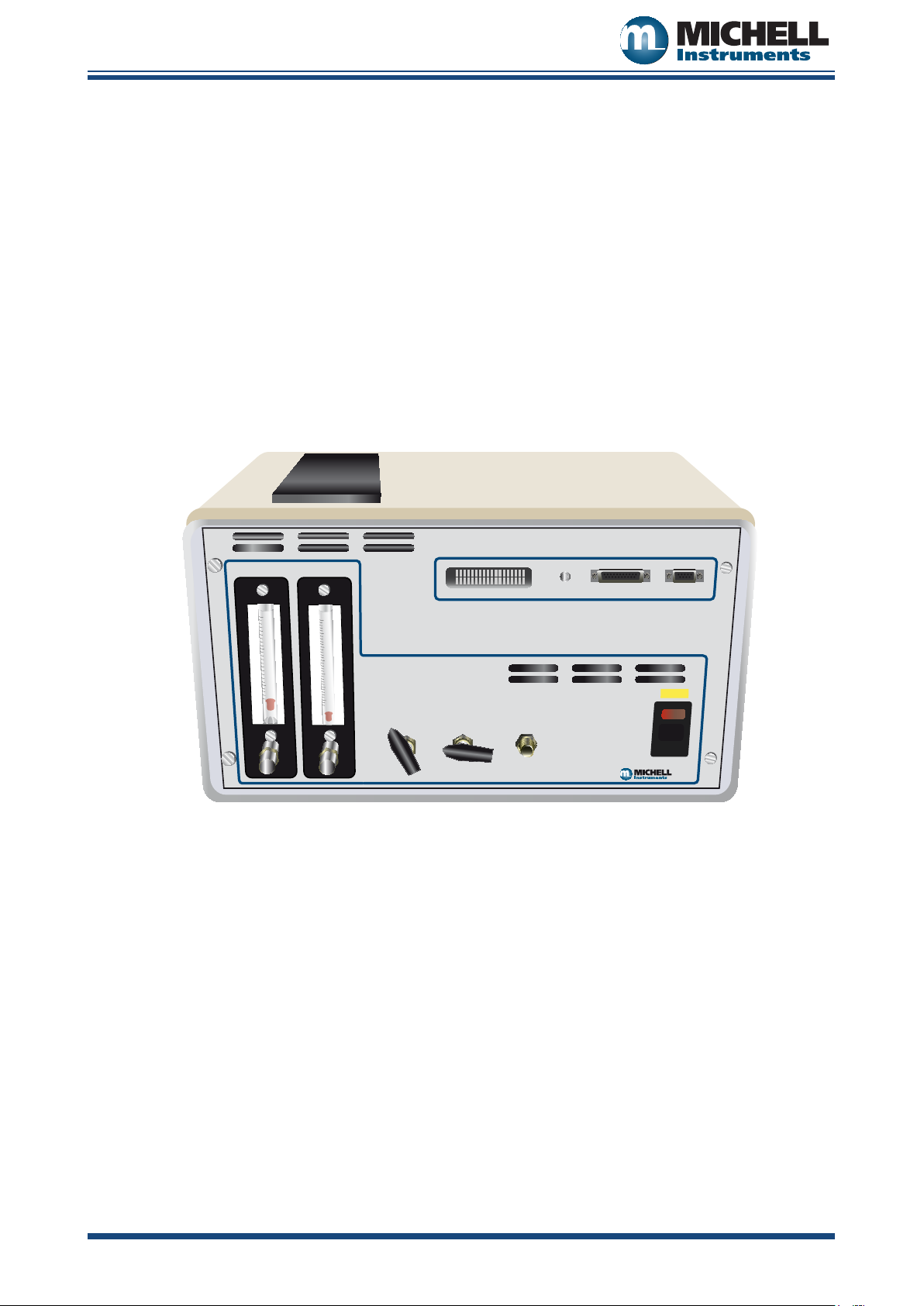
HG-1 Humidity Generator
DRY FLOW WET FLOW
1
.
5
0
.
5
2
1
2
.
5
0
.
2
0
.
4
0
.
6
0
.
8
1
.
0
1
.
2
1
.
4
INTERNAL
GAS SUPPLY
TEST
CHAMBER
GAS IN
COMPRESSED
AIR
240V
Display Control
Outputs
Communications
Humidity Calibrator
User’s Manual
97053 Issue 11, December 2010 Michell Instruments
Page 2

Inside front cover (blank)
Page 3
HG-1 User’s Manual
HG-1 Humidity Generator
DRY FLOW WET FLOW
1
.
5
0
.
5
2
1
2
.
5
0
.
2
0
.
4
0
.
6
0
.
8
1
.
0
1
.
2
1
.
4
INTERNAL
GAS SUPPLY
TEST
CHAMBER
GAS IN
COMPRESSED
AIR
240V
Display Control
Outputs
Communications
HG-1
© 2010 Michell Instruments
This document is the property of Michell Instruments Ltd. and may not be copied or otherwise reproduced,
communicated in any way to third parties, nor stored in any Data Processing System without the express
written authorization of Michell Instruments Ltd.
97053 Issue 11, December 2010 iii Michell Instruments
Page 4

HG-1 User’s Manual
97053 Issue 11, December 2010 iv Michell Instruments
Contents
Safety ..............................................................................................................................................vi
Electrical Safety .........................................................................................................................vi
Toxic Materials ..........................................................................................................................vi
Repair and Maintenance.............................................................................................................vi
Calibration ................................................................................................................................vi
Safety Conformity ......................................................................................................................vi
Abbreviations ...................................................................................................................................vii
Warnings ........................................................................................................................................ viii
Recycling Policy ............................................................................................................................... viii
WEEE And RoHS Compliance ..............................................................................................................ix
Calibration Facilities ...........................................................................................................................ix
Manufacturing Quality ........................................................................................................................ix
Warranty .......................................................................................................................................... x
Return Policy ..................................................................................................................................... x
1 INTRODUCTION ........................................................................................................................ 1
1.1 General .......................................................................................................................... 1
1.2 Calibration ...................................................................................................................... 1
2 INSTALLATION .......................................................................................................................... 2
2.1 Filling the Saturator ....................................................................................................... 2
2.2 Gas Connections ............................................................................................................ 2
2.3 Electrical Connections ..................................................................................................... 2
2.3.1 Power Supply ............................................................................................................. 2
2.3.2 Current Outputs .......................................................................................................... 3
2.3.3 Relay Outputs ............................................................................................................. 3
2.3.4 Digital Communications ............................................................................................... 3
3 OPERATION .............................................................................................................................. 4
3.1 Operating Overview ....................................................................................................... 4
3.2 Dynamic Contamination Correction (DCC) ......................................................................... 5
3.3 Data Hold Phase ............................................................................................................. 6
3.4 Display Screens .............................................................................................................. 7
3.5 Operating Procedure ....................................................................................................... 9
4 MAINTENANCE .........................................................................................................................10
4.1 Re-Filling the Saturator System .......................................................................................10
4.2 Gas Drying Unit Replacement .........................................................................................10
4.3 Cleaning the Cooled Mirror Sensor ..................................................................................11
4.4 Re-Calibration of the Humidity Calibrator ........................................................................12
5 APPLICATION SOFTWARE .........................................................................................................13
5.1 Virtual Hygrometer ........................................................................................................13
5.2 Parameter Setup ............................................................................................................14
5.3 Charting and Logging .....................................................................................................16
5.4 Statistics .......................................................................................................................18
5.5 Control Parameters ........................................................................................................18
5.6 Calibration Correction .....................................................................................................19
5.7 Change of Password ......................................................................................................21
Page 5

HG-1 User’s Manual
Michell Instruments v 97053 Issue 11, December 2010
Figures
Figure 3.1 Graphical representation of system phases ..............................................................5
Figure 3.2 Graphical representation of the Data Hold Phase ......................................................6
Figure 3.3 Optidew Display Screens and Navigation .................................................................8
Figure 4.1 Potentiometer Location ........................................................................................11
Figure 5.1 Virtual Hygrometer window ..................................................................................13
Figure 5.2 Parameter Setup window ......................................................................................14
Figure 5.3 Chart/Log Control Panel window ...........................................................................16
Figure 5.4 Chart window ......................................................................................................17
Figure 5.5 Basic Statistics window .........................................................................................18
Figure 5.6 Extracts from Calibration Certicates .....................................................................19
Figure 5.7 Calibration Correction window ...............................................................................21
Figure 5.8 Change Password window ....................................................................................21
Figure A.1 HG-1 Set-Up Diagram ...........................................................................................24
Figure A.2 HG-1 Flow Diagram .............................................................................................. 25
Tables
Table 2.1 Channel 1 and 2 Output Connections .......................................................................3
Table 2.2 Relay Output Connections .......................................................................................3
Table 2.3 RS232/RS485 Connections .......................................................................................3
Table 3.1 Guide to setting owrates for required RH or dew point ............................................ 9
Appendices
Appendix A Technical Specications ......................................................................................... 23
Appendix B List of Worldwide Michell Instruments’ Ofces ......................................................... 27
Page 6

HG-1 User’s Manual
97053 Issue 11, December 2010 vi Michell Instruments
Safety
The manufacturer has designed this equipment to be safe when operated using the procedures detailed in this
manual. The user must not use this equipment for any other purpose than that stated. Do not apply values
greater than the maximum value stated.
This manual contains operating and safety instructions, which must be followed to ensure the safe operation
and to maintain the equipment in a safe condition. The safety instructions are either warnings or cautions
issued to protect the user and the equipment from injury or damage. Use competent personnel using good
engineering practice for all procedures in this Manual.
Electrical Safety
The instrument is designed to be completely safe when used with options and accessories supplied by the
manufacturer for use with the instrument.
Toxic Materials
The use of hazardous materials in the construction of this instrument has been minimized. During normal
operation it is not possible for the user to come into contact with any hazardous substance which might be
employed in the construction of the instrument. Care should, however, be exercised during maintenance and
the disposal of certain parts.
Repair and Maintenance
The instrument must be maintained either by the manufacturer or an accredited service agent. Refer to
Appendix B for details of Michell Instruments’ worldwide ofces’ contact information.
Calibration
The recommended calibration interval for the HG-1 is one year. The instrument should be returned to the
manufacturer, Michell Instruments, or one of their accredited service agents for re-calibration.
Safety Conformity
This product meets the essential protection requirements of the relevant EU directives. Further details of
applied standards may be found in the product specication.
Page 7

HG-1 User’s Manual
Michell Instruments vii 97053 Issue 11, December 2010
Abbreviations
The following abbreviations are used in this Manual:
A Ampere
AC alternating current
bar pressure unit (=100 kP or 0.987 atm)
ºC degrees Celsius
ºF degrees Fahrenheit
dp dew point
DC direct current
ft/sec feet per second
g/kg grams per kilogram
g/m3 grams per cubic meter
in inch(es)
kg kilogram(s)
lb pound
l/min liters per minute
m meter(s)
mA milliampere
max maximum
min minimum
mm millimeters
m/sec meters per second
% percentage
PSI pounds per square inch
RS232 serial data transmission standard
RS485 serial data transmission standard
SCFH standard cubic feet per hour
temp temperature
V Volts
Ω Ohms
Page 8
HG-1 User’s Manual
97053 Issue 11, December 2010 viii Michell Instruments
Warnings
The following general warnings listed below are applicable to this instrument. They are repeated in the text in
the appropriate locations.
Where this hazard warning symbol appears in the following
sections it is used to indicate areas where potentially
hazardous operations need to be carried out.
Where this symbol appears in the following sections it is used
to indicate areas of potential risk of electric shock.
Recycling Policy
Michell Instruments is concerned with the protection of the environment. It is our commitment to reduce
and eliminate from our operations, wherever possible, the use of substances which may be harmful to the
environment. Similarly, we are increasingly using recyclable and/or recycled material in our business and
products wherever it is practical to do so.
The product that you have purchased may contain recyclable and/or recycled parts and we will be happy to
provide you with information on these components if required.
Page 9

HG-1 User’s Manual
Michell Instruments ix 97053 Issue 11, December 2010
WEEE And RoHS Compliance
The Waste Electronic and Electrical Equipment (WEEE) Directive, and the Restriction of Hazardous Substances
(RoHS) Directive place rules upon European manufacturers of electrical and electronic equipment. The
directives’ aim is to reduce the impact that electronic devices have on the environment.
Michell products are currently exempt from the RoHS directive, however all future products will be developed
entirely using compliant materials. Furthermore, Michell is taking active steps to remove non-compliant
materials and components from existing products wherever possible.
Michell is in full compliance with the WEEE Directive (Registration No. WEE/JB0235YW). Customers may be
required to return certain instruments for treatment at the end of their working life.
June 2010
Calibration Facilities
Michell Instruments’ calibration facilities are among the most sophisticated in the world and have been
recognized for their excellence.
Traceability to the National Physical Laboratory (NPL) UK is achieved through our UKAS Accreditation
(Number 0179). This covers dew point over the range -90 to +90°C (-130 to +194°F) and also Relative
Humidity.
Dew-point calibrations are also traceable to the National Institute for Standards & Technology (NIST) USA over
the range -75 to +20°C (-103 to +68°F).
NOTE: Standard traceable calibration certicates for instruments and sensors are not issued
under our UKAS accreditation. UKAS certicates are usually to special order and are clearly
identied.
Manufacturing Quality
Michell Instruments is registered with the British Standards Institute for Quality Assurance to:
BS EN ISO 9001: 2008
Rigorous procedures are performed at every stage of production to ensure that the materials of construction,
manufacturing, calibration and nal test procedures meet the requirements laid down by our BSI approved
Quality System.
Please contact Michell Instruments if the product does not arrive in perfect working order.
Page 10

HG-1 User’s Manual
97053 Issue 11, December 2010 x Michell Instruments
Warranty
Unless otherwise agreed, the Supplier warrants that, as from the date of delivery for a period of 12 months
the goods and all their component parts, where applicable, are free from any defects in design, workmanship,
construction or materials.
The Supplier warrants that the services undertaken shall be performed using reasonable skill and care, and of
a quality conforming to generally accepted industry standards and practices.
Except as expressly stated, all warranties, whether express or implied, by operation of law or otherwise, are
hereby excluded in relation to the goods and services to be provided by the Supplier.
All warranty services are provided on a return to base basis. Any transportation costs for the return of a
warranty claim shall reside with the Customer.
Return Policy
If a Michell Instruments’ product malfunctions within the warranty period, the following procedure must be
completed:
Notify a Michell Instruments’ distributor, giving full details of the problem, the 1.
model variant and the serial number of the product.
If the nature of the problem indicates the need for factory service then the 2.
instrument should be returned to Michell Instruments, carriage prepaid,
preferably in the original packaging, with a full description of the fault
and the customer contact information.
Upon receipt, Michell Instruments will evaluate the product to determine the 3.
cause of the malfunction. Then, one of the following courses of action will
be taken:
If the fault is covered under the terms of the warranty, the instrument •
will be repaired at no cost to the owner and returned.
If Michell Instruments determines that the fault is not covered under •
the terms of the warranty, or if the warranty has expired, an estimate
for the cost of the repairs, at standard rates, will be provided. Upon
receipt of the owner’s approval to proceed, the product will be repaired
and returned.
Page 11

HG-1 User’s Manual
Michell Instruments 1 97053 Issue 11, December 2010
1 INTRODUCTION
1.1 General
The Michell Humidity Calibrator is a high precision, yet simple to operate, humidity calibration system designed
for calibrating relative humidity instruments over the range 2 to 90%RH (-30 to 20°Cdp (-22 to 68°Fdp) at
ambient temperature and atmospheric pressure.
A Michell Optidew Dew-Point Transmitter is utilized to function as a reference instrument.
The Humidity Calibrator consists of the following:
a mini compressor and gas drying unit (to provide its own dry gas supply) or •
alternatively an external dry compressed air supply
owmeters including valves (to indicate and mix gas ows) •
a saturator system (to provide the wet gas supply) •
a calibration test chamber (for housing humidity instruments under test) or •
alternatively a gas outlet port (for feeding the generated sample gas to an
external humidity instrument under test)
The generated humidity is visible through the instrument display and analog outputs.
Humidities are generated by the proportional mixing of wet and dry gas ows through calibrated owmeters
and ne metering valves. The generated sample gas is measured by the Optidew cooled mirror dew-point
sensor situated within the calibration test chamber along with other humidity measuring ‘instruments under
test’.
The Humidity Calibrator is a fully portable, self-contained instrument requiring only mains power and an
occasional top-up of the saturator with distilled water for operation. Access for maintenance is made available
through the removable top and rear panel of the instrument.
1.2 Calibration
A Certicate of Dew-Point Calibration is provided with the instrument, which means that the instrument
has been calibrated against Michell Calibration Standards. It is also possible to provide a UKAS Calibration
Certicate giving direct calibration traceability of the instrument to NPL Standards. Please contact Michell
Instruments for further details.
Page 12

HG-1 User’s Manual
97053 Issue 11, December 2010 2 Michell Instruments
2 INSTALLATION
The Humidity Calibrator is supplied with a power cable. Please check that all items listed on the packing check
list have been received.
The Humidity Calibrator enclosure is designed for bench top mounting in a laboratory environment. Allow
sufcient clearance at the rear of the enclosure for maintenance and ventilation.
2.1 Filling the Saturator
Before operation, the saturator requires lling with distilled water.
Carefully unscrew and remove the lling port knurled nut and red plastic cap located on the rear panel of the
unit.
Fill the saturator with clean distilled water to a level indicated on the label (viewed through the rear panel).
The water level should be kept between the minimum and maximum marks on the label. Too little water will
reduce the efciency of the saturator, too much will cause erratic operation.
Replace the lling port red plastic cap and knurled nut.
2.2 Gas Connections
All gas connections to/from the calibrator are 6mm OD Swagelok® tube ttings.
2.3 Electrical Connections
2.3.1 Power Supply
A single phase mains power supply is required to operate this unit as indicated by the yellow label located on
the front panel of the unit. The user cannot change the power supply voltage as this involves replacing internal
electromechanical parts.
The power supply connection is a 3-pin IEC plug located on the front panel of the unit.
A 3-core power cable is provided, the free end of which should be wired to a suitable earthed plug or directly
via a fused power spur. Power cable conductors are color coded according to the convention:
Brown L (Live)
Blue N (Neutral)
Green/Yellow E (Earth)
WARNING
This instrument must be connected to electrical earth for safety
Page 13

HG-1 User’s Manual
Michell Instruments 3 97053 Issue 11, December 2010
2.3.2 Current Outputs
There are two current source outputs which can be set to either 4-20 or 0-20 mA and scaled by the user over
the range –200 to +1000 by use of the supplied Optidew application software. Factory set default is 4-20 mA
over the range 0 to +100°C (+32 to +212°F).
The Channel 1 mA output can be set for dew point, %RH, g/m3, g/kg, temperature or ∆(t - tdp). Channel 2
outputs temperature only.
The connections for both of these outputs are via the 15 way ‘D’ type connector. Connection details are as
follows:
Pin number Current Output
3
1 Channel 1 - dew point, %RH, g/m
2 Channel 1 – 0 V
3 Channel 2 - temperature
4 Channel 2 – 0 V
, g/kg, temperature, ∆(t - tdp)
Table 2.1 Channel 1 and 2 Output Connections
2.3.3 Relay Outputs
Two sets of relay outputs are available via the 15 way D type connector. They are the optics fault/alarm relay
and a status relay.
The optics fault/alarm relay changes state either to indicate that the Optidew sensor mirror and optics require
cleaning or when the process variable exceeds the alarm set-point value.
The status relay changes state when the instrument is in DCC (Dynamic Contamination Control), DATA HOLD,
or if the system has an optics fault.
Pin number Current Output
9 Optics Fault / Alarm Relay N/O
10 Optics Fault / Alarm Relay COM
11 Optics Fault / Alarm Relay N/C
12 Status Relay N/O
13 Status Relay COM
14 Status Relay N/C
Table 2.2 Relay Output Connections
2.3.4 Digital Communications
The 9 way ‘D’ connector is used to communicate with the Optidew via the application software or by an ASCII
terminal program.
The communication interface is RS232 as standard or RS485 as a factory settable option.
Pin number RS232 RS485
2 Tx B
3 Rx A
5 GND GND
Table 2.3 RS232/RS485 Connections
Page 14

HG-1 User’s Manual
97053 Issue 11, December 2010 4 Michell Instruments
3 OPERATION
Check all connections are in accordance with the installation instructions.
3.1 Operating Overview
It is important not to over-tighten the metering valves
when closing-off either the dry or wet ow paths, as
this will cause permanent damage to the valves.
The combined owmeter and metering valves on the front panel indicate and control the humidity output of
the unit. By mixing the wet and dry gas ows in different ratios, different humidities can be generated. After
mixing, the gas ows into the test chamber and over the sensors under test. The Optidew Cooled mirror sensor
is also installed in the chamber, and provides a reference dew-point measurement.
To the right of the display is a multi function button marked ‘DISPLAY CONTROL’, which allows the user to
scroll through the different measurement parameters available.
In order to communicate digitally with the instrument, through the RS232 output, it is necessary to change
the display to ‘REMOTE MODE’. This can be achieved by holding the ‘DISPLAY CONTROL’ button down for 7
seconds - the mode change will then be conrmed on the display. To continue using the display, hold down the
button for a further 7 seconds - the display will then switch back to LOCAL mode.
Page 15

HG-1 User’s Manual
Michell Instruments 5 97053 Issue 11, December 2010
DCC
Min Hold Time
Measurement Time
DCC
Time
Temp
Extended DCC
Mirror Contamination > 2%
from last DCC
Mirror Temp Boosted
3.2 Dynamic Contamination Correction (DCC)
Dynamic Contamination Control (DCC) is a unique compensation system that eliminates loss of measurement
accuracy, due to mirror surface contamination. DCC consists of a self-learning prediction algorithm that
adapts itself to its operating conditions in order to achieve optimum performance at all times. Although fully
automatic, ne-tuning is possible to suit extreme operating conditions.
At switch-on, the system initiates a DCC to measure the surface condition of the mirror. During this phase,
the mirror surface is heated above the dew point and the instruments’ status is indicated by the display status
LED and the setting of Channel 1 mA output to 23 mA. The end of the DCC duration will result in the system
cooling the mirror surface to form condensation. Once system control is reached, the measurement phase
will begin, indicated by the change in status of the instrument and reection of the measured parameter in
Channel 1’s mA value.
The system will remain in the measurement phase until the end of the measurement time, after which a DCC
will initiate, while maintaining Channel 1’s mA value. During this, and any subsequent DCC, the new level
of mirror contamination is compared with the one before and, if above a predetermined level, will initiate
an increase in the mirror temperature to drive off any residual condensate before recording the new level of
contamination. The duration of the increased mirror temperature can be up to four times the DCC duration,
depending upon conditions.
Figure 3.1 Graphical representation of system phases
Page 16

HG-1 User’s Manual
97053 Issue 11, December 2010 6 Michell Instruments
Temp
DCC
Min Hold
Time
Adaptive Hold
Time
Hold On Analogue O/P Released
3.3 Data Hold Phase
During DATA HOLD, the level of the Channel 1 mA output is held and the Status Relay and Status LED are
energized and illuminated respectively, until the system has stabilized onto the measured dew point. The DATA
HOLD phase will nish when the following two conditions are met:
the minimum hold time has expired, and•
the system is stable to within a specied stability band•
The minimum hold time is nominally set to 4 minutes, and generally, under most conditions, the system will
be stable within this time period. However, there may be some conditions where the system may take longer
to stabilize, so under these conditions an adaptive hold algorithm takes over to determine when stability is
reached. If, under extreme conditions, the system fails to stabilize within the set stability band, the
HOLD phase will terminate when the maximum hold time is reached.
When the DATA HOLD nishes - the Status LED will turn off, the Status Relay will de-energize and the hold on
Channel 1 mA output will be released. The system will now be in its continuous measurement phase, where it
will remain until the measurement time has elapsed and the next DCC cycle initiates.
DATA
Figure 3.2 Graphical representation of the Data Hold Phase
Page 17

HG-1 User’s Manual
Michell Instruments 7 97053 Issue 11, December 2010
3.4 Display Screens
Below is a description of the parameters and system status information shown on each screen.
Screen 1: Displays the status of the Optidew
It will show
DCC, DATA HOLD, OPTICS ALARM or MEASURE according to the
current status of the Optidew instrument.
Screen 2: Peltier power and the Mirror condition
Peltier power indicates how much the heat pump is depressing in order to measure
the dew point. When the peltier power has a value of 100% and does not reduce
over an extended period of time, it means that the heat pump is at maximum
depression. In normal operation this indicates that the dew point is lower than
the present mirror temperature and therefore cannot be measured. Reducing
the sensor ambient temperature by use of additional cooling will increase the
measurement range of the instrument in applications where the peltier power
>95%.
Alongside the peltier power value is an indicator that shows the control stability.
When this indicator shows
CNTRL, it indicates the system is controlling the mirror
temperature on the dew point. COOL indicates the system is depressing the heat
pump in order to form dew on the mirror surface. HEAT indicates a rapid increase
in dew-point level, whereby the system needs to increase the temperature of the
mirror surface to read this new dew-point value.
The Mirror condition indicates the amount of signal received back from the mirror
which includes both the level of moisture and contamination on the mirror surface.
In
DCC mode this display will only show the amount of mirror contamination and,
if greater than 80% after a DCC, will initiate an optics alarm condition.
Screen 3: Humidity in %RH and ambient temperature
Screen 4: Humidity in dew-point and ambient temperature
-1
Screen 5: Humidity in gkg
Screen 6: Humidity in gm
Screen 7: The rst line in this screen displays ∆ (t – t
and ambient temperature
-3
and ambient temperature
). This is the difference
dp
between ambient temperature and dew point. Note that this parameter will be
equal to 0 if the dew point is higher than the ambient temperature (e.g. during a
DCC cycle). The second line displays the ambient temperature.
Screen 8: The rst line displays a
line displays ambient temperature.
, which is equivalent to RH/100. The second
W
Page 18

HG-1 User’s Manual
97053 Issue 11, December 2010 8 Michell Instruments
Transmitter
Optidew Display
Screen 1
Screen 2
Screen 3
Screen 4
Screen 5
Screen 6
Screen 7
Screen 8
Start up
banner
During DCC, Hold
and Optics Alarm
Status = MEASURE
Mirror: 50 %
Peltier: 40 % COOL
tdp 0.0 ºC
t 10.0 ºC
rh 49.7 %
t 10.0 ºC
Y 106.00 gkg
-1
t 10.0 ºC
t 10.0 ºC
dV 106.00 gm
-3
t 10.0 ºC
(t-tdp) 10.0 ºC
t 10.0 ºC
a
0.5
Optidew Display Screens
and Navigation
Apply
Power
Figure 3.3 Optidew Display Screens and Navigation
Page 19

HG-1 User’s Manual
Michell Instruments 9 97053 Issue 11, December 2010
3.5 Operating Procedure
The procedure is as follows:
Switch the Gas Supply Selection Valve to either internal/external supply.1.
Switch on the power to the Humidity Calibrator. The Optidew instrument will 2.
enter
DCC mode.
When power is applied the display will initially show test characters for 3.
approximately 0.5 seconds, after which the start-up banner will be displayed
for approximately 7 seconds. The instrument will start up in
After the start-up banner has expired, the display will show screen 1. This 4.
displays the status of the Optidew Instrument. To scroll to screen 2, press
and release the display control button. It is not possible to view any other
screens until the
a small delay before the display changes to the next screen; this
is normal. After the DATA HOLD period has nished, screen 3 will appear.
All eight screens can now be accessed by depressing the display control
button.
DATA HOLD period is complete. NOTE: There may be
LOCAL mode.
Using the ‘5.
the humidity/dew-point temperature required. The following table shows the
approximate owrate settings required for generating various humidities/dewpoint temperatures. If a sequence of humidities/dew points are required,
it is important to start at the driest and select progressively through the
range, always moving from dry to wet. This will drastically reduce the time
taken for the generator to stablize at each point. Allow sufcient time for
the instrument to thermally stabilize before monitoring humidity/dew-point
readings.
Required Relative
Humidity (%)
10 -10 2.5 0.2
21 0 2.5 0.6
45 10 1.5 1.2
60 15 0.7 1.3
90 20 0 1.5
NOTE: These settings are only intended as a guide. The user will have to “ne tune” each setting
for accurate humidities/dew points. These settings are calculated at an operating temperature
of 23 °C. Therefore, if the operating temperature changes or the efciency of the gas drying unit
deteriorates then these settings will not be accurate.
Wet Flow’ and ‘Dry Flow’ metering valve and owmeters set
Required Dew
Point (ºC)
Dry Flow Flowrate
(l/min)
Wet Flow Flowrate
(l/min)
Table 3.1 Guide to setting owrates for required RH or dew point
When the dry gas supply from the gas drying unit deteriorates the 6.
Dry
Flow setting will have to be increased and the Wet Flow setting decreased
to compensate for the wetter supply gas. The compensation required will
be greater at the lower humidities and eventually it will be impossible to
generate the lower humidities. At this point the gas drying unit will need
replacing/regenerating.
If the external dry compressed air supply is used the 7.
have to be decreased and the Wet Flow setting increased to compensate for
the dryer air supply.
Prior to shut-down, always return the calibrator to the ‘8.
setting and allow the generator to run for several minutes to purge out the
moisture in the system.
Dry Flow setting will
Full Dry’ (<10% RH)
Page 20

HG-1 User’s Manual
97053 Issue 11, December 2010 10 Michell Instruments
4 MAINTENANCE
Routine maintenance of the Michell Humidity Calibrator is limited to the following tasks:
Re-Filling the Saturator System•
Gas Drying Unit Replacement•
Cleaning the Optidew Cooled Mirror Sensor•
Re-calibration of the Humidity Calibrator•
4.1 Re-Filling the Saturator System
The frequency of re-lling the saturator system is dependent on the humidities being generated. High humidities
will consume far more water than low humidities. The efciency of the saturator system will reduce if the level
of water is allowed to reduce. Michell Instruments recommends that the saturator level is checked prior to
use on a daily basis.
Fill the saturator system following the steps below:
Disconnect the power supply to the calibrator.1.
Carefully unscrew and remove the lling port knurled nut and red plastic cap 2.
located on the rear panel of the unit.
Fill the saturator with clean distilled water to a level (viewed through the rear 3.
panel). The water level is not critical but should be kept above the minimum
level and below the maximum level.
Replace the lling port red plastic cap and knurled nut and resume normal 4.
operation.
4.2 Gas Drying Unit Replacement
The calibrator is tted with a desiccant dryer column to dry the air supply drawn from ambient. It is accessible
from the rear panel of the unit.
The frequency of desiccant/dryer unit replacement is dependent upon the length of time in operation.
Typically the gas drying unit can continually generate low humidities for a minimum period of 24 hours before
replacement is required.
The desiccant provides an indication of its condition by a change in color: - blue represents a dry active
condition whereas a deep pink represents a wet exhausted condition.
Michell Instruments recommends initially that the gas drying unit be examined on a daily basis, and then
depending on the condition, increase/decrease the maintenance period accordingly. Replacement Gas Drying
Unit type - Aldrich type Z11287-9.
To replace the gas drying unit follow the steps below:
Disconnect the power supply to the calibrator and remove the rear panel.1.
Locate and release the gas drying unit from its retaining clips and remove the 2.
tubing from the gas ports at each end of the unit. Regenerate the desiccant
or replace with a new/regenerated gas drying unit.
To regenerate the desiccant, remove it from the acrylic column and spread 3.
evenly on a tray. Heat for 1 hour at about 200°C. The desiccant should then
be cooled in an air tight container before relling back into the acrylic column.
The felt lters should also be dried out at about 100°C for 30 minutes.
Re-assemble the gas drying unit into the calibrator and replace the rear panel 4.
and resume normal operation.
Page 21

HG-1 User’s Manual
Michell Instruments 11 97053 Issue 11, December 2010
Potentiometer
Front Panel
Desiccant
Column
Chamber
Saturator
Display
4.3 Cleaning the Cooled Mirror Sensor
Throughout the life of the Optidew Cooled Mirror Sensor, periodic cleaning of the mirror surface and optics window
may be required, depending upon operational conditions and exposure of the sensor to contamination.
Sensor cleaning is mandatory if the instrument indicates an optics fault. The cleaning procedure is as
follows:
Switch the instrument off, or, if it is required to leave it on, a 1. DCC cycle must
be performed. Remove the test chamber cover.
Clean the mirror surface and optics window with a cotton bud soaked in 2.
distilled water. If the sensor has been exposed to oil based contamination
then use one of the following solvents: methanol, ethanol, or isopropyl
alcohol.
When cleaning is complete, replace the test chamber cover and switch the 3.
instrument on if necessary and observe the mirror contamination value
during the
case and adjust the potentiometer until this value is reached, ensuring that
the adjustments are made ONLY during the
under-range the display will ash 0%, indicating that a positive adjustment
is required.
DCC phase. If this value is not 0%, then remove the lid of the
DCC phase. If this value is
NOTE: There will be a delay of approximately 5 seconds between the actual adjustment and the
displayed value changing.
NOTE: If the mirror contamination value displays ‘low’ next to 0% (on display), or ashes
0% (through PC interface), this indicates that the value is below 0%, and needs positive
adjustment.
Figure 4.1 Potentiometer Location
4.4 Re-Calibration of the Humidity Calibrator
The Optidew is inherently drift free by design. However, as with any high quality measuring instrument, regular
re-calibrations against standards are recommended.
This work can only be done by exposure of the Optidew Cooled Mirror Sensor to sample gases of known
moisture content using calibrated test equipment traceable to national standards.
Michell Instruments recommends that the Optidew Dew-Point Transmitter is re-calibrated on an annual basis
to ensure its accuracy.
Page 22

HG-1 User’s Manual
97053 Issue 11, December 2010 12 Michell Instruments
5 APPLICATION SOFTWARE
The application software is an interface to the Optidew that provides a display of the measured and calculated
parameters, system status, charting and logging, statistical information and a facility to view and change the
system parameters.
5.1 Virtual Hygrometer
The Virtual Hygrometer window provides a display for the instrument by showing the measured parameters
and status.
The Humidity display has the ability to show dew point (°C/°F), %RH, gm-3, gkg-1, ∆ (t – tdp) or aW by clicking
on the ‘Change Units’ button. Selecting one of these options will show the measured or calculated value, but
will not change the Channel 1 mA output of the instrument, as this can only be done via the parameter set-up
window, see Section 5.2. When the software is executed, it will default to the present setting of Channel 1 mA
output. The ambient temperature is constantly shown in the lower display. NOTE: The Humidity display
will blink if the dew point is higher than the temperature. This is normal and not a fault.
Mirror Condition indicates the amount of signal received back from the mirror, which includes both the level
of moisture and contamination on the mirror surface. In DCC mode this display will only show the amount of
mirror contamination and, if greater than 80% after a DCC, an optics alarm condition will initiate.
Instrument status is shown via the ve colored indicators. In DCC (initiated automatically or by the ‘DCC
Initiate’ button), both the DCC and Hold indicators will illuminate showing the DCC status and the hold on
Channel 1 mA output. When the DCC period ends, the DCC indicator will turn off leaving only the Hold
indicator illuminated until the system enters the measurement phase. The Fault indicator will illuminate after
a DCC if cleaning of the mirror surface is required. Refer to Section 4 for details of mirror cleaning.
The Alarm indicator will illuminate when the measured variable exceeds the alarm set point (if selected) (refer
to Section 5.2).
Figure 5.1 Virtual Hygrometer window
Page 23

HG-1 User’s Manual
Michell Instruments 13 97053 Issue 11, December 2010
Max Cool can be initiated by the ‘Max Cool On’ button. Once initiated, the Max Cool indicator will illuminate
and the system will drive the heat pump into maximum depression. This feature can be used to ascertain if
the measured dew point is within the measurement capability of the instrument.
Clicking on the ‘Statistics’ button allows maximum, minimum and average values of the measured parameters
to be viewed. See Section 5.4.
Charting and logging of the measured values can be initiated by clicking on the ‘Chart/log’ button. See
Section 5.3.
The ‘Hold display in DCC mode’ check box stops the system from updating the display during DCC, when
enabled. The display is held when DCC is initiated and is not updated until both DCC and Hold periods have
expired.
5.2 Parameter Setup
The Parameter Setup window allows the setting and ranging of Channel 1 and 2 mA outputs, the duration for
DCC, Measurement and Hold, and the values for atmospheric pressure and alarm set points.
The Display Units and Channel 1 mA Output are selected by clicking the left hand mouse button in the relevant
box. This will change the settings of both the instrument and the virtual hygrometer window. Changing the
mA outputs from 4-20 mA to 0-20 mA & vice versa will change both Channel 1 & Channel 2 mA outputs.
Figure 5.2 Parameter Setup window
Page 24

HG-1 User’s Manual
97053 Issue 11, December 2010 14 Michell Instruments
The maximum and minimum values of Channel 1 and Channel 2 are –200 to +1000 respectively, therefore
allowing the range of the outputs to be anywhere between these limits. The values for Max and Min must be
integer values with a difference between them of at least 1°C/F.
If Channel 1 is to be set for % RH, gm-3, gkg-1 or ∆ (t – tdp), then the minimum value of Channel 1 Min should
be 0, as a negative value for these parameters is not possible.
The pressure value is used to correct gm-3 and gkg-1 for atmospheric pressure. By entering the atmospheric
pressure the display and Channel 1 mA output (if either gm-3 or gkg-1 is selected) will both be corrected
accordingly.
The Alarm can be set to OFF or set to be active on any of the process variables i.e. dew point, ambient
temperature, temperature difference, % RH, gm-3 or gkg-1 as shown above. The set point needs to be an
integer value between –200 and +1000, although negative set points are only valid for dew point and ambient
temperature. If the process variable exceeds the set point, the Alarm indicator on the virtual hygrometer will
illuminate and the Optics Fault/Alarm relay will change state.
To change any of the values, enter the required value and click on the return key. The background of the text
box will change to yellow to indicate that the change is taking place. When conrmation has been received
that the instrument has accepted the change, the background will change back to green.
NOTE: When the Parameter Setup window is open, the values in the Virtual Hygrometer window are frozen. The Parameter Setup window needs to be closed for the software to resume normal
display mode.
Page 25

HG-1 User’s Manual
Michell Instruments 15 97053 Issue 11, December 2010
5.3 Charting and Logging
Clicking on the ‘Chart/log’ button in the Virtual Hygrometer window brings up the Chart / log control panel
window.
The chart, in its default conguration, displays dew point, temperature and % RH. However, gm-3, gkg-1 and
∆(t – tdp), can be added by clicking in the appropriate check box.
Within the Global section, you can select the charting and logging interval from a minimum of 5 seconds to a
maximum of 1 hour. It offers the facility to log the temperature of the mirror while in DCC and Hold, or hold
the measured value while in these modes and chart the held data values accordingly.
To log the measured and calculated humidity values to a data le for further analysis, click on the check box
in the Logging section and specify a le name by clicking on the ‘Browse’ button. If a log le is not required
simply uncheck the box.
To Run, Pause and Stop the charting and logging facility, use the chart control buttons accordingly.
Figure 5.3 Chart/Log Control Panel window
Page 26

HG-1 User’s Manual
97053 Issue 11, December 2010 16 Michell Instruments
Clicking on the ‘Run’ button will bring up the chart as shown below. The chart shows the measured and
calculated humidity values selected in the
is possible to scale, zoom and scroll both X and Y axis of the chart by using the controls in the Chart Settings
window, which can be activated by clicking on the ‘Chart Settings’ button in the Chart window.
Chart section, with an assigned identiable color for each value. It
Figure 5.4 Chart window
The X & Y axes can be individually scaled. The X-axis can be scaled by using the ZoomX feature in the Chart
mode
section, while the Y-axis can be scaled by changing the min and max values, or selecting a parameter
in the Auto-scale list, which scales the Y-axis to the actual values of the parameter.
There are a number of modes associated with the chart, which can be selected from the Chart mode list;
Plot, Scroll (X, Y, & XY), Cursor, Zoom (X, Y, & XY) and Zoom Box. In order to use the scrolling and zooming
modes, make your selection and click the left mouse button on the chart itself, moving the mouse across the
chart accordingly with the left mouse button held down. This will zoom or scroll the chart accordingly.
Individual data points can be selected from the chart by using the cursor mode. Select the parameter in
question by clicking on a legend on the right hand side of the chart (°C dew point is shown as selected above)
and moving the cursor to the point of interest - the actual value with its time stamp will be displayed above
the chart.
Page 27

HG-1 User’s Manual
Michell Instruments 17 97053 Issue 11, December 2010
5.4 Statistics
Clicking on the ‘Statistics’ button on the Virtual Hygrometer window will display the Basic statistics window
as shown below:
Figure 5.5 Basic Statistics window
This window shows the maximum, minimum and average of each parameter since the program began taking
readings from the instrument, or since the re-set button was pressed.
5.5 Control Parameters
The control parameters (protected by a password) should only
be amended by trained personnel in order to adjust the system
for operation in extreme conditions. Contact a Michell Technical
Representative for details (see contact information in Appendix B).
Page 28

HG-1 User’s Manual
97053 Issue 11, December 2010 18 Michell Instruments
5.6 Calibration Correction
Every Optidew is delivered with a Calibration Certicate detailing the deviation at each measurement point
from a known reference value. Data provided on the Calibration Certicate is normally arranged as shown in
the following extracts:
Extract from a UKAS Calibration Certicate:
Generated
Dew point
°C
-39.89 -40.11 -20 +0.22 ±0.26
-20.10 -20.31 0 +0.21 ±0.22
0.39 0.20 21 +0.19 ±0.18
Extract from a Standard Calibration Certicate:
Dew-point
Temperature
°C
Generated
Dew point
°C
-40.1 -40.2
-20.1 -20.1
0.2 0.1
Sensor
Temperature
Test Hygrometer
°C
°C
Instrument
Display °C
Correction
Required
Expanded
Uncertainty
°C
Figure 5.6 Extracts from Calibration Certicates
From time to time the Optidew may be calibrated by an external calibration agency, where similar data will be
provided.
Page 29

HG-1 User’s Manual
Michell Instruments 19 97053 Issue 11, December 2010
The Calibration Correction window is a utility that allows an authorized user to input calibration information in
order to effect a real-time correction of the displayed, charted and logged data within the Opti-Soft application
software.
Data for dew-point temperature and ambient temperature, both in units of °C, may be entered for correction
purposes, along with the original Calibration Certicate reference number and date of calibration, providing
full traceability of data. Once the correction data has been applied, by clicking on the check box, the main
Virtual Hygrometer window will indicate that corrected data is being displayed and will show the Calibration
Certicate number and date. This information is also saved to the Log le for data export.
Figure 5.7
on the next page shows the Calibration Correction window. Four sets of data may be entered:
DP Ref Dew-point data for the reference hygrometer (sometimes
called the actual dew point or the standard)
DP Reading Measured dew-point value of the Optidew under test
Temp Ref Temperature data from the reference thermometer
Temp Reading This is the measured temperature value of the Optidew
under test
Data can be entered for between 3 and 11 different dew-point and temperature calibration points. If no
data is inserted, no calibration correction is possible. Data should be entered with the highest dew-point
and temperature values at the top of the page, in descending value order to the bottom. If out-of-sequence
data or spurious characters are entered, the software will raise a warning message and bad data must be reentered.
Calibration Certicate Number eld is an optional entry eld and is alphanumeric. Any information
The
entered into this eld will be displayed on the main Virtual Hygrometer window when calibration correction
is enabled. In addition it will be saved to the Log le. Similarly, the date of calibration may be entered for
display and logging when correction is enabled.
Page 30

HG-1 User’s Manual
97053 Issue 11, December 2010 20 Michell Instruments
Once all necessary data has been entered in the Calibration Correction window, click on the Use Calibration
Date to Correct Measure Values check box and then click on Apply and Close to return to the main Virtual
Hygrometer display. Upon the next update, the corrections entered will be applied to all displayed and logged
data, and a legend above the display will indicate this fact. To remove
check box and click on Apply, then on Close.
Calibration Correction, de-select the
Figure 5.7 Calibration Correction window
NOTE: Enter the calibration data in descending order so the highest values are in row 1 as shown
above.
5.7 Change of Password
The initial password is “Michell”. This can be changed after entering the Control and Calibration Data
windows. Selecting the Change Password menu item will display the following window where you can enter
a new password with up to 20 alphanumeric characters. The password is not case sensitive.
Figure 5.8 Change Password window
Page 31

HG-1 User’s Manual
Michell Instruments 21 97053 Issue 11, December 2010
Appendix A
Technical Specications
Page 32

HG-1 User’s Manual
97053 Issue 11, December 2010 22 Michell Instruments
Appendix A Technical Specications
Humidity Calibrator
Range 2 to 90% RH (-30 to +20°Cdp (-22 to +68°Fdp))
@ 21°C ambient
Accuracy Typically ±1% RH, ±0.2°Cdp, ±0.1°C temperature
3
Measurement Units dew point (°C/°F), % RH, temperature (°C/°F), g/m
Display 2 x 20 character, vacuum uorescent
Resolution 0.1°C
Outputs analog: 4-20 mA or 0-20 mA over user settable output
accuracy ±0.2°C
500 Ω Maximum Load Resistance
digital: RS232 @ 9600 baud rate
alarms: volt free contact, 2 A @ 30 V DC, 0.5 A @ 120 V AC
Gas Inlet Pressure 1 to 8 bar (14 to 116 PSI)
Gas Outlet Flow 0.5 to 4 l/min (1 to 8.5 SCFH) (dew point dependant)
Saturator Polycarbonate and porous polyethylene sinter
Desiccant 1¼lb 8-mesh indicating ‘Drierite’
Power 100-120 V or 220-240 V, 50/60 Hz
Power Consumption 60 V-A
Power Supply Fuse 3.15 A (F) quick blow
Operating Temperature +18 to +24°C (+64 to +75°F)
Enclosure Painted aluminium 520 x 320 x 400mm (20 x 12.6 x 15.7in) (w x h x d)
Weight 20kg (44lb) approximately
, g/kg
Cooled Mirror Sensor
Peltier 2 stage
Photo Detection System Single visible red spectrum
Mirror Gold plated copper
Temperature Measurement 4 wire 100 Ω platinum resistance thermometer
Sample Wetted Part Acetal housing with glass optics window
Operating Temperature -40 to +90°C (-40 to +194°F)
Flow Velocity 1 to 10 m/sec (3 to 32 ft/sec)
Dew-Point Range -60 to +90°C (-76 to +194°F)
Temperature Range -40 to +90°C (-40 to +194°F)
RH Range <0.5 to 100%
Depression (@ 21°C ambient) -45°C (-49°F)
Page 33

HG-1 User’s Manual
Michell Instruments 23 97053 Issue 11, December 2010
Saturator
Filling Port
REAR VIEW
Gas Dryer
Unit
Ventilation
Fans
Saturator
Bottle
Removable
Clear Panel
305mm (12”)
Humidity
Display
Outputs
Connector
RS232 COMMS
Connector
Power ON/OFF
Switch
Power Supply
Connection
External Gas
Inlet
Air Supply
Selection
Valve
Wet Flow
Flowmeter
and Valve
Dry Flow
Flowmeter
and Valve
Display Control
Switch
400mm (15.75”)
520mm (20.47”)
Recessed Carry
Handles
Optidew
Transmitter
Optidew Sensor
and Temperature
Probe
Calibration Test Chamber
Plastic Removable Cover
(User Configurable Space
is 170 x 100 x 100mm)
Figure A.1 HG-1 Set-Up Diagram
Page 34

HG-1 User’s Manual
97053 Issue 11, December 2010 24 Michell Instruments
SATURATOR
0.1 - 1.5 L/MIN
WET FLOWMETER
AND VALVE
0.2 - 2.5 L/MIN
DRY FLOWMETER
AND VALVE
SWITCHING
BALL VALVE
PRESSURE
REGULATOR
GAS
DRYER
OUTLET PRESSURE
PRESET TO 10 PSIG
CALIBRATION
TEST CHAMBER
TEMPERATURE
PROBE
OPTIDEW
SENSOR
VENT
OPTIDEW
TRANSMITTER
COMPRESSED AIR
(8 BARG MAX)
AMBIENT AIR
PUMP
Figure A.2 HG-1 Flow Diagram
Page 35

HG-1 User’s Manual
Michell Instruments 25 97053 Issue 11, December 2010
Appendix B
List of Worldwide Michell
Instruments’ Ofces
Page 36

HG-1 User’s Manual
97053 Issue 11, December 2010 26 Michell Instruments
Appendix B List of Worldwide Michell Instruments’ Ofces
Asia
Michell Asia
PO Box 3149
Joondalup
WA 6027
Australia
Tel: +61 893 046587
E-mail: au.info@michell.com
Web: www.michell.com/au
China
Michell Instruments (Shanghai) Ltd
Room 505, Qilai Building
889 Yishan Road
Shanghai, 200233
P R China
Tel: +86 21 5401 2255
Fax: +86 21 5401 2085
E-mail:
cn.info@michell.com
Web: www.michell.com/cn
Germany, Austria, Switzerland
Michell Instruments GmbH
Industriestrasse 27
D-61381 Friedrichsdorf
Germany
Tel: +49 6172 591700
Fax: +49 6172 591799
E-mail:
de.info@michell.com
Web: www.michell.com/de
Benelux
Michell Instruments Benelux BV
Krombraak 11
4906 CR Oosterhout
The Netherlands
Tel: +31 162 680 471
Fax: +31 162 437 566
E-mail: nl.info@michell.com
Web:
www.michell.com/nl
France
Michell Instruments SAS
2-4, rue Jean Desparmet
69008 Lyon
France
Tel: +33 437 53 88 20
Fax: +33 437 53 88 21
E-mail: fr.info@michell.com
Web: www.michell.com/fr
Italy
Michell Italia Srl
Via Capecelatro, 10
20148 Milano
Italy
Tel: +39 02 4047194
Fax: + 39 02 40010565
E-mail: it.info@michell.com
Web: www.michell.com/it
Japan
Michell Japan KK
Musashino Center Building
1-19-18 Nakacho, Musashino
Tokyo 180-0006
Japan
Tel: +81 422 502600
Fax: +81 422 521700
E-mail: info@michell-japan.co.jp
Web: www.michell-japan.co.jp
North America
Michell Instruments Inc
319 Newburyport Turnpike, Suite 207
Rowley, MA 01969
USA
Tel: +01 978 484 0005
Fax: +01 978 843 7669
E-mail:
us.info@michell.com
Web: www.michell.com/us
Middle East
Michell Instruments Middle East
P-06, #097
Sharjah Airport Int’l free zone
Sharjah,
United Arab Emirates
Tel: +971 6 5575028
+971 6 5575029
Fax:
E-mail: me.info@michell.com
United Kingdom
Michell Instruments Ltd
48 Lancaster Way Business Park
Ely, CB6 3NW
Cambridgeshire
England
Tel: +44 1353 658000
Fax: +44 1353 658199
E-mail: info@michell.com
Web: www.michell.com/uk
Page 37

http://www.michell.com
 Loading...