

Page 1
ES70
Sampling System
User’s Manual
97506 Issue 1
December 2017
Page 2

Please fi ll out the form(s) below for each instrument that has been purchased.
Use this information when contacting Michell Instruments for service purposes.
Instrument
Code
Serial Number
Invoice Date
Location of Instrument
Tag No
Instrument
Code
Serial Number
Invoice Date
Location of Instrument
Tag No
Instrument
Code
Serial Number
Invoice Date
Location of Instrument
Tag No
Page 3

ES70
Sampling System
For Michell Instruments' contact information please go to
www.michell.com
© 2017 Michell Instruments
This document is the property of Michell Instruments Ltd. and may not be copied or
otherwise reproduced, communicated in any way to third parties, nor stored in any Data
Processing System without the express written authorization of Michell Instruments Ltd.
Page 4

ES70 User’s Manual
Contents
Safety ................................................................................................................................vi
Electrical Safety ...........................................................................................................vi
Pressure Safety ............................................................................................................vi
Toxic Materials .............................................................................................................vi
Repair and Maintenance ...............................................................................................vi
Safety Conformity ........................................................................................................vi
Abbreviations .....................................................................................................................vii
Warnings ...........................................................................................................................vii
1 INTRODUCTION ............................................................................................VIII
1.1 Materials ......................................................................................................... viii
1.2 System Designs ................................................................................................ viii
1.3 Filtration and Fast Loop ....................................................................................... 1
1.4 Pressure / Flow Control and Measurement ........................................................... 1
1.5 Mounting Variants ............................................................................................. 1
1.6 Enclosure Environmental Control ........................................................................ 1
2 INSTALLATION ..................................................................................................2
2.1 Sampling System Installation ............................................................................... 2
2.1.1 Mounting Details ........................................................................................... 2
2.1.2 Gas Connections ........................................................................................... 2
2.1.3 Electrical Connections .................................................................................... 2
3 OPERATION ......................................................................................................3
3.1 Sampling Start-Up Procedure ............................................................................... 3
3.2 Sample Flow ‘Start-Up’ Procedure ........................................................................ 3
4 GOOD MEASUREMENT PRACTICE .......................................................................4
5 MAINTENANCE ..................................................................................................5
5.1 General Maintenance Guidelines .......................................................................... 5
5.2 Filter Element Maintenance ................................................................................. 5
5.2.1 Particulate Filter Maintenance ........................................................................ 5
5.2.2 Coalescing Filter Maintenance ........................................................................ 7
5.3 Transmitter Maintenance ..................................................................................... 9
Figures
Figure 1 Particulate Filter Maintenance 1 ...................................................................5
Figure 2 Particulate Filter Maintenance 2 ...................................................................6
Figure 3 Particulate Filter Maintenance 3 ...................................................................6
Figure 4 Particulate Filter Maintenance 4 ...................................................................6
Figure 5 Coalescing Filter Maintenance 1 ...................................................................7
Figure 6 Coalescing Filter Maintenance 2 ...................................................................7
Figure 7 Coalescing Filter Maintenance 3 ...................................................................8
Figure 8 Coalescing Filter Maintenance 4 ...................................................................8
Figure 9 Coalescing Filter Maintenance 5 ...................................................................8
Figure 11 Outdoor Enclosure Dimensions ..................................................................12
Figure 10 Indoor Panel Dimensions ..........................................................................12
iv 97506 Issue 1, December 2017
Page 5

ES70 User’s Manual
Appendices
Appendix A Technical Specifi cations .............................................................................. 11
Appendix B Quality, Recycling & Warranty Information ...................................................14
Appendix C Return Document & Decontamination Declaration ........................................ 16
Michell Instruments v
Page 6

ES70 User’s Manual
Safety
The manufacturer has designed this equipment to be safe when operated using the procedures
detailed in this manual. The user must not use this equipment for any other purpose than that
stated. Do not apply values greater than the maximum value stated.
This manual contains operating and safety instructions, which must be followed to ensure the safe
operation and to maintain the equipment in a safe condition. The safety instructions are either
warnings or cautions issued to protect the user and the equipment from injury or damage. Use
competent personnel using good engineering practice for all procedures in this manual.
Electrical Safety
The instrument is designed to be completely safe when used with options and accessories supplied
by the manufacturer for use with the instrument.
Pressure Safety
DO NOT permit pressures greater than the safe working pressure to be applied to the instrument.
Refer to Appendix A, Technical Specifi cations.
Toxic Materials
The use of hazardous materials in the construction of this instrument has been minimized. During
normal operation it is not possible for the user to come into contact with any hazardous substance
which might be employed in the construction of the instrument. Care should, however, be exercised
during maintenance and the disposal of certain parts.
Repair and Maintenance
The instrument must be maintained either by the manufacturer or an accredited service agent. Refer
to www.michell.com for details of Michell Instruments’ worldwide offi ces contact information.
Safety Conformity
This product meets the essential protection requirements of the relevant EU directives.
vi 97506 Issue 1, December 2017
Page 7

ES70 User’s Manual
Abbreviations
The following abbreviations are used in this manual:
AC alternating current
barg pressure unit (=100 kP or 0.987 atm)
ºC degrees Celsius
ºF degrees Fahrenheit
DC direct current
dp dew point
Hz Hertz
kg kilogram(s)
lb pound
Nl/min normal liters per minute
mA milliampere
max maximum
min minute(s)
% percentage
psig pounds per square inch
scfh standard cubic feet per hour
temp temperature
V Volts
W Watts
Ω Ohms
Warnings
The following general warning listed below is applicable to this instrument. It is repeated
in the text in the appropriate locations.
Where this hazard warning symbol appears in the following
sections it is used to indicate areas where potentially hazardous
operations need to be carried out.
Michell Instruments vii
Page 8

INTRODUCTION
1 INTRODUCTION
Michell Instruments designs and manufactures a broad range of sampling systems for a
wide spectrum of industries and processes from the economical compressed air market
to the oil and gas process market.
Sample extraction, handling and conditioning techniques are of critical importance to
assure optimal performance and reliability of all analysers which accurately quantify
specifi c components within a process gas or liquid composition. With a wide variety
of options required for pressure and fl ow control, fi ltration, isolation and sample
temperature control it can be diffi cult to see what is really required to get maximum
performance from your analysers in any given application.
The ES70 series is designed to simplify sample system confi guration by providing a set
of choices for all requirements, such as panel or enclosure mount, fi ltering, upstream
and downstream pressure and fl ow control etc. This provides a quick and simple method
to choose all the required components suitable for the application requirements.
1.1 Materials
ES70 User’s Manual
To ensure continuous and reliable dew-point or moisture measurement it is important
that the dew-point transmitter is exposed to stable conditions of the gas to be monitored.
The ES70 systems utilizes high quality materials which ensure that the sample gas
travels smoothly through the system.
Gas wetted parts:
• Stainless steel tube, fi lter housing and fi ttings (316 stainless steel)
• Filter element (oleo-phobic membrane or stainless steel mesh)
• Single- or dual-stage pressure reduction
• Transmitter sample block (316 stainless steel)
• Flowmeter (borosilicate glass) with Viton® seals or high-pressure rated
armored type
1.2 System Designs
Our sampling system designs ensure that dew-point and moisture measurements can be
performed in the most suitable conditions. The ES70 sampling systems can be supplied
in various confi gurations and are designed to be used in conjunction with other Michell
products, as follows:
• Easidew PRO XP Transmitter
• Easidew PRO I.S. Transmitter (with or without display)
• Promet I.S. (with or without pressure transmitter)
• Liquidew I.S.
Process connections are available with either 6mm or 1/4” tube fi ttings.
viii 97506 Issue 1, December 2017
Page 9

ES70 User’s Manual
1.3 Filtration and Fast Loop
If the sample contains impurities it is crucial to remove the contaminants before they reach
the sensing device. A fast-loop bypass fl ow arrangement can also be included to reduce
sample fl ow response time lag and to enable the fi lter to be drained automatically of any
potential hydrocarbon liquids and hydrates formed. The ES70 system can be supplied with
various fi ltration and fast loop options;
• Particulate Filter: 5 micron Stainless Steel Mesh
• Coalescing Filter with manual drain
• Combined coalescing/oleophobic membrane with continuous drain fl ow
(fast loop) - with Single Stage Regulation & Glass tube (20 barg rated) or
Armoured fl ow meter (138 barg rated) with integral fl ow metering valve.
• Combined coalescing/oleophobic membrane with continuous drain fl ow
(fast loop) - with Two Stage Regulation & Armoured fl ow meter (138 barg
rated) with integral fl ow metering valve
INTRODUCTION
1.4 Pressure / Flow Control and Measurement
Various options are available for management of pressure and fl ow within the sampling
system;
• Upstream and Downstream, single stage or two stage pressure regulation,
with a choice of gauges.
• Downstream fl ow metering with a choice of glass tube or armoured fl ow
meters.
1.5 Mounting Variants
Depending on the application the sampling system can be supplied in 3 variations:
• Mounted on an open panel for indoor systems
• Mounted in an Outdoor Enclosure, IP66/NEMA4X rated, with window, 304
grade stainless steel
• Mounted in an Outdoor Enclosure, IP66/NEMA4X rated, with window, 316
grade stainless steel
1.6 Enclosure Environmental Control
Sampling systems fi tted within enclosures may need heating to maintain a constant
temperature environment of at least 10oC above the highest envisaged dew point
temperature independent of surrounding temperature variations. Similarly, the enclosure
may require cooling when ambient temperatures rise in summer months.
• Electrical heating with a choice of 20°C or 40°C set-point thermostats.
• Vortex Cooling with thermostat control (instrument air required)
recommended for climates exceeding 45°C.
• Trace heated sample tubing is available as a factory supplied option.
Michell Instruments 1
Page 10
INSTALLATION
2 INSTALLATION
2.1 Sampling System Installation
It is essential that the connection of electrical and gas supplies
to this instrument be undertaken by competent personnel.
Relevant sections of this manual must be read in full before
commencing measurement (see below).
ES70 User’s Manual
2.1.1 Mounting Details
The ES70 base plate or enclosure is designed to be wall-mounted. It should be rigidly mounted
vertically in a position free from high vibration levels and shaded from direct sunlight.
Dimensional drawings are shown in Appendix A
2.1.2 Gas Connections
Gas connections to the ES70 are via 6mm or ¼” Swagelok® tube fi ttings located at the
base of the mounting plate or enclosure.
Connections are marked as follows:
GAS IN Sample gas entry point with a maximum supply pressure of 138 barg (2,000spig)
GAS OUT Sample gas exit point for connection to atmospheric vent or fl are (up to maximum 3 barg)
Care must be taken to ensure that the outlet isolation valve is
not fully closed.
2.1.3 Electrical Connections
All cables to or from the sampling system should go through the M20 plastic cable gland
provided at the base of the enclosure.
2 97506 Issue 1, December 2017
Page 11
ES70 User’s Manual
3 OPERATION
3.1 Sampling Start-Up Procedure
The ES70 sampling system is designed for continuous operation.
Immediately after the power is applied, the dew-point transmitter will begin operation
and all output signals will be live.
It is essential that the connection of electrical and gas supplies
to this instrument be undertaken by competent personnel.
Relevant sections of this manual must be read in full before
commencing measurement (see below).
OPERATION
3.2 Sample Flow ‘Start-Up’ Procedure
Refer to 'As Built' drawings for actual pressure and fl ow values.
Proceed as follows:
1. Ensure the outlet isolation valve is fully CLOSED.
2. Open the inlet isolation valve slowly, making sure that the pressure
indicated on the pressure gauge does not exceed the maximum operational
pressure. If achievable, ensure that the inlet isolation valve is fully OPEN.
3. Adjust the outlet isolation valve, setting the sample gas fl ow rate to the
value shown on the system fl ow diagram.
4. Allow the sample gas to purge the system for the period of time indicated
in the Good Measurement Practice Section (Stabilization Times).
Michell Instruments 3
Page 12

GOOD MEASUREMENT PRACTICE
4 GOOD MEASUREMENT PRACTICE
The ES70 is designed to operate in a fl owing gas stream and is suitable for the
measurement of the moisture content of a wide variety of gases. In general, if the gas
(in conjunction with water vapor) is not corrosive to ceramics or base metals then it will
be suitable for measurement by the ES70.
The system is designed for operation with sample gas fl ow rates of 1-5 Nl/min (sample
block). Ideally, the fl ow rate should be set-up between 4 and 6 Nl/min. Flow regulation
is provided within the ES70. Always use high quality valve gear, coupling connections
and pipework.
The system will operate successfully at fl ow rates within its operational range and it is
important to ensure that the fl ow rate through the sample block is high enough to avoid
long time lags in response to humidity changes at the sample source.
Avoid pressure gradients in the system by placing excessive fl ow restriction on the
output side of the sample block. In applications where the test gas has a very high
fl ow rate, an instrument by-pass arrangement is preferable to fl ow restriction after the
transmitter.
ES70 User’s Manual
Flow Rates
Theoretically fl ow rate has no direct effect on the measured moisture content, but in
practice it can have unanticipated effects on response speed and accuracy. The optimal
fl ow rate varies depending on the measurement technology, and can always be found
in the instrument or sensor manual.
An inadequate fl ow rate can:
• Accentuate adsorption and desorption effects on the gas passing through the
sampling system.
• Allow pockets of wet gas to remain undisturbed in a complex sampling
system, which will then gradually be released into the sample fl ow.
• Increase the chance of contamination from back diffusion: ambient air that
is wetter than the sample can fl ow from the exhaust back into the system. A
longer exhaust (sometimes called a pigtail) can also help alleviate this problem.
• Slow the response of the sensor to changes in moisture content.
An excessively high fl ow rate can:
• Introduce back pressure, causing slower response times potential changes
in expected dew point.
Stabilization Times
Ensure that the system has suffi cient time to stabilize before taking any readings.
Typically the system should be allowed at least 24hrs to stabilize, but for measurements
below -60°C dew point, up to 5 days should be allowed for the system to reach total
equilibrium with the sample, given the very low moisture contents involved.
4 97506 Issue 1, December 2017
Page 13

ES70 User’s Manual
5 MAINTENANCE
5.1 General Maintenance Guidelines
Routine maintenance of the sampling system is confi ned to fi lter element replacement
and regular recalibration of the dew-point transmitter.
5.2 Filter Element Maintenance
The composition of the gas determines the frequency of the fi lter element replacement,
i.e. liquid and particulate contaminates, corrosive elements etc.
A disposable fi lter element continues to fi lter at its original effi ciency as long as it is kept in
service. The life of the element is determined by the increase in fl ow resistance caused by
trapped solids in the element. The element should be changed when the fl ow falls below an
acceptable level, or the pressure drop becomes too high. In any case the element should
be replaced before the pressure drop across it reaches 0.7 barg (10.2 psig). The disposable
fi lter elements cannot be cleaned as the solids are trapped within the depth of the element
not on the surface.
MAINTENANCE
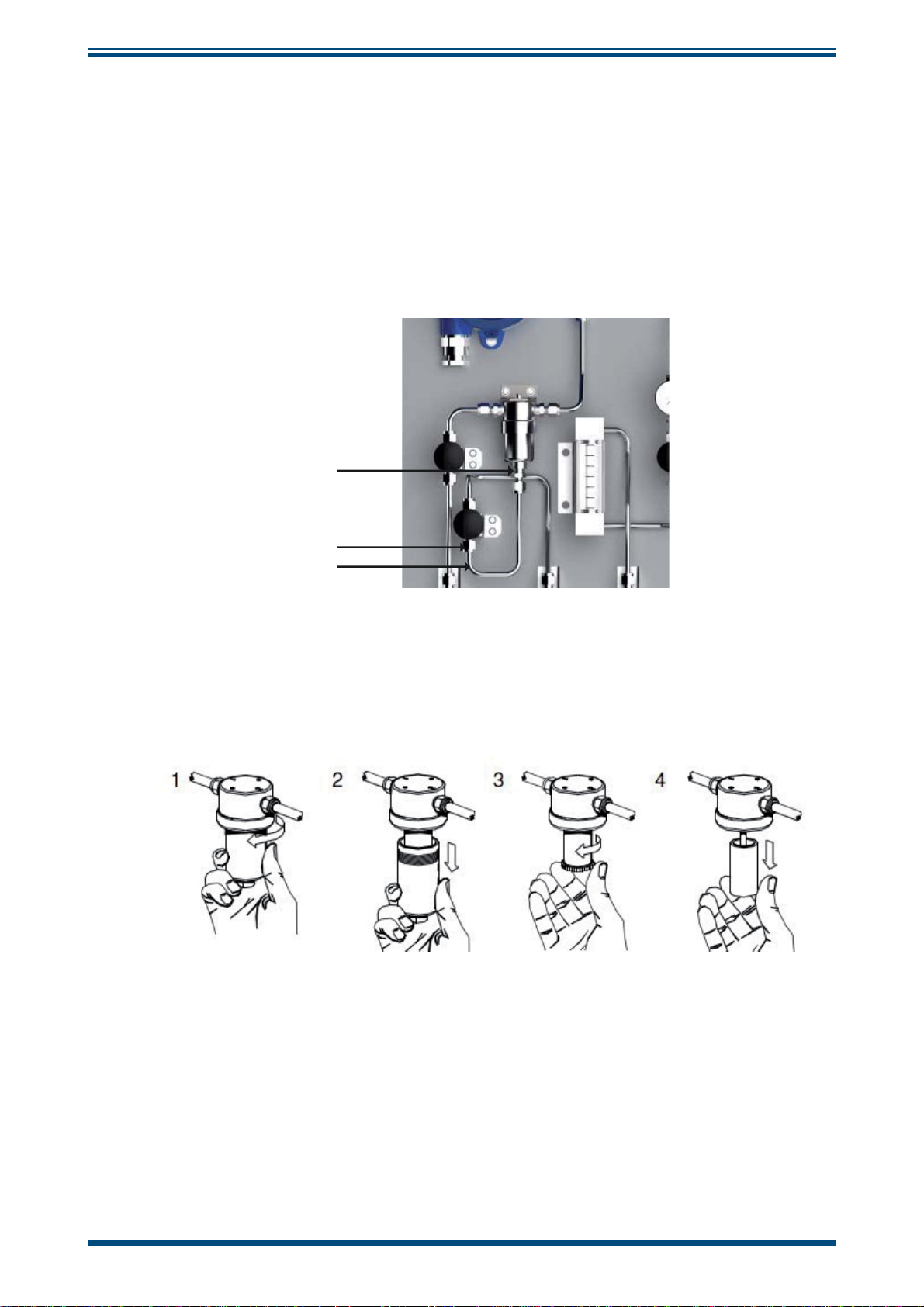
5.2.1 Particulate Filter Maintenance
To replace the particulate fi lter element proceed as follows:
1. Isolate any gas supplies to the sampling system.
NOTE: Wear protective gloves when handling the fi lter housing.
2. Remove the bowl (1,2), element retainer (3) and fi lter element (4).
Figure 1
Particulate Filter Maintenance 1
NOTE: In order to untighten the bowl a spanner/wrench may be needed.
Michell Instruments 5
Page 14

MAINTENANCE
ES70 User’s Manual
Figure 2
Disposable and sintered PTFE fi lter elements are sealed by compression against a fl at surface
(5). Gaskets are not required between the fi lter element and components of the housing.
The element is located by guides which fi t the inside diameter of the tube at each end.
Figure 3
The fi lter tube is securely sealed by tightening the element retainer a 1/4 to 1 turn
after it fi rst contacts the fi lter element, the amount will depend on the housing type and
element size. A mark on the end of the retainer is used as a guide.
3. Before replacing the housing bowl ensure that the mating threads and
sealing faces are clean and damage free. It is recommended that the
threads and sealing faces are lubricated with a small amount of silicone
grease before assembly.
Particulate Filter Maintenance 2
Particulate Filter Maintenance 3
4. Re-connect the tube with its fi tting to its original confi guration.
Figure 4
5. Resume normal system operation by opening up the gas supplies to the
sampling system as described in the relevant section of the Start-up
Procedures (Section 3).
Particulate Filter Maintenance 4
6 97506 Issue 1, December 2017
Page 15
ES70 User’s Manual
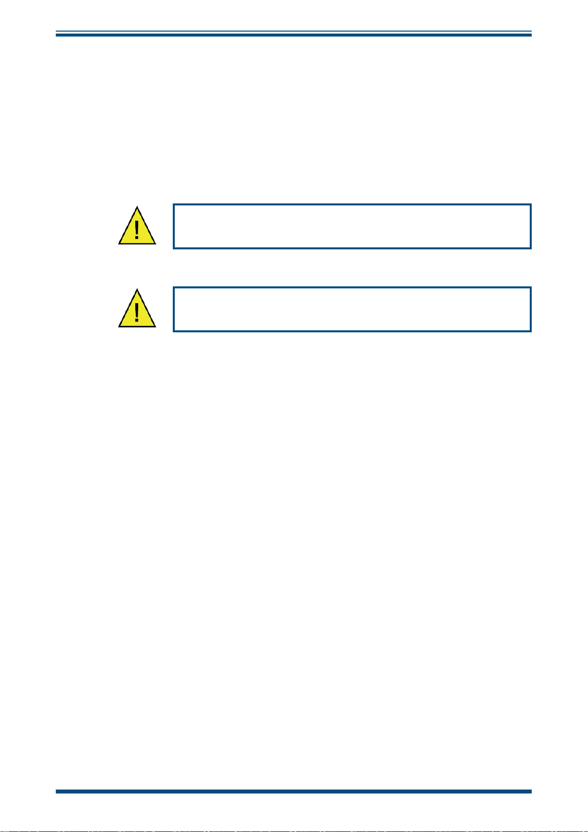
5.2.2 Coalescing Filter Maintenance
To replace the coalescing fi lter element proceed as follows:
1. Isolate any gas supplies to the sampling system.
NOTE: Wear protective gloves when handling the fi lter housing.
2. Unscrew the couplings (1 and 2) on the picture below
1
MAINTENANCE
2
3
Figure 5
3. Disconnect the tube with its fi tting (3).
4. Remove the bowl (1,2), element retainer (3) and fi lter element (4).
Figure 6
Coalescing Filter Maintenance 1
Coalescing Filter Maintenance 2
NOTE: In order to untighten the bowl a spanner/wrench may be needed.
Michell Instruments 7
Page 16

MAINTENANCE
ES70 User’s Manual
Figure 7
Disposable and sintered PTFE fi lter elements are sealed by compression against a fl at surface
(5). Gaskets are not required between the fi lter element and components of the housing.
The element is located by guides which fi t the inside diameter of the tube at each end.
Figure 8
The fi lter tube is securely sealed by tightening the element retainer a 1/4 to 1 turn after it
fi rst contacts the fi lter element, the amount will depend on the housing type and element
size. A mark on the end of the retainer is used as a guide.
5. Before replacing the housing bowl ensure that the mating threads and
sealing faces are clean and damage free. It is recommended that the
threads and sealing faces are lubricated with a small amount of silicone
grease before assembly.
Coalescing Filter Maintenance 3
Coalescing Filter Maintenance 4
6. Re-connect the tube with its fi tting to its original confi guration.
Figure 9
7. Resume normal system operation by opening up the gas supplies to the
sampling system as described in the relevant section of the Start-up
Procedures (Section 3).
Coalescing Filter Maintenance 5
8 97506 Issue 1, December 2017
Page 17

ES70 User’s Manual
5.3 Transmitter Maintenance
Calibration
Routine maintenance of the Easidew transmitter is confi ned to regular re-calibration
by exposure of the Easidew to sample gases of known moisture content to ensure that
the stated accuracy of the Easidew is maintained. Calibration services traceable to the
UK National Physical Laboratory (NPL) and the US National Institute of Standards and
Technology (NIST) are provided by Michell Instruments.
Michell Instruments offers a variety of re-calibration and exchange sensor schemes to
suit specifi c needs. A Michell representative can provide detailed, custom advice (for
Michell Instruments’ contact information go to www.michell.com).
Transmitter replacement
The composition of the gas determines the frequency of the transmitter replacement,
i.e. liquid and particulate contaminates, corrosive elements, etc.
It is recommended that the transmitter is changed on an annual basis to maintain the
accuracy of the system.
MAINTENANCE
Michell Instruments can provide an exchange transmitter. Prior to recalibration being
necessary, an exchange transmitter can be ordered from Michell Instruments or any
authorized dealer. Once the transmitter and calibration certifi cate have been received it
can be fi tted and the original transmitter returned to Michell Instruments.
To replace the transmitter, proceed as follows:
1. Isolate the sampling system from the sample gas supply and switch off all
electrical supplies.
2. Disconnect the wiring from the transmitter and the sample tubes from
the sample block. Remove the transmitter and sample block from the
sampling system.
3. Remove the sample block from the transmitter.
4. Fit a new/recalibrated transmitter ensuring the bonded seal is positioned
between the transmitter and the sample block.
5. Refi t the transmitter and sample block to the sampling system and
reconnect the sample tubes and transmitter cable (see Sample Block
Section of the Easidew PRO XP Manual 97442).
6. Resume normal system operation by opening up the gas supplies to the
sampling system in accordance with the relevant section of the Start-up
Procedures (Section 3).
Michell Instruments 9
Page 18

APPENDIX A
ES70 User’s Manual
Appendix A
Technical Specifi cations
10 97506 Issue 1, December 2017
Page 19

ES70 User’s Manual
APPENDIX A
Appendix A Technical Specifi cations
Operating Specifi cations
Operating Temperature -15 to +60°C (+5 to +140°F)
Operating Inlet Pressure Up to 138 barg dependent on confi guration
Flow Rate 1 to 5 Nl/min (2.1 to 10.6 scfh)
Mechanical Specifi cations
Process Connection and Material Inlet/outlet connections via 6mm or ¼” stainless
steel fi ttings, 316 stainless steel
Stainless steel tube, fi lter housing and fi ttings (316
Gas Wetted Parts
Ingress Protection
Indoor
Outdoor
Dimensions
Indoor base plate
Outdoor SS enclosure
Pressure and Flow Control Via isolation valves, pressure gauge and fl owmeter
Gas Filtration
stainless steel), Filter element, Transmitter sample
block (316 stainless steel), Flowmeter (borosilicate
glass) with Viton® seals
No protection (base plate only)
IP66, NEMA 4X
750 x 750 x 2mm (29.5 x 29.5 x 0.07") (h x w x d)
800 x 800 x 300mm (31.4 x 31.4 x 11.8") (h x w x d)
Particulate Filter: 5 micron stainless steel mesh or
Combined coalescing/oleophobic fi lter
Michell Instruments 11
Page 20

APPENDIX A
Dimensions
Indoor
750 29.5"
770 30.3"
ES70 User’s Manual
750 29.5"
700 27.6"
Outdoor
838 33"
800 31.5"
Figure 10
800 31.5"
758 29.8"
Indoor Panel Dimensions
300 11.8"
Figure 11
Outdoor Enclosure Dimensions
12 97506 Issue 1, December 2017
Page 21

ES70 User’s Manual
APPENDIX B
Appendix B
Quality, Recycling
& Warranty
Information
Michell Instruments 13
Page 22

APPENDIX B
ES70 User’s Manual
Appendix B Quality, Recycling & Warranty Information
Michell Instruments is dedicated to complying to all relevant legislation and directives.
Full information can be found on our website at:
www.michell.com/compliance
This page contains information on the following directives:
• ATEX Directive
• Calibration Facilities
• Confl ict Minerals
• FCC Statement
• Manufacturing Quality
• Modern Slavery Statement
• Pressure Equipment Directive
• REACH
• RoHS2
• WEEE2
• Recycling Policy
• Warranty and Returns
This information is also available in PDF format.
14 97506 Issue 1, December 2017
Page 23

ES70 User’s Manual
APPENDIX C
Appendix C
Return Document
&
Decontamination Declaration
Michell Instruments 15
Page 24

APPENDIX C
ES70 User’s Manual
Appendix C Return Document & Decontamination Declaration
'HFRQWDPLQDWLRQ&HUWL¿FDWH
IMPORTANT NOTE: Please complete this form prior to this instrument, or any components, leaving your
site and being returned to us, or, where applicable, prior to any work being carried out by a Michell
engineer at your site.
Instrument Serial Number
Warranty Repair? YES NO Original PO #
Company Name Contact Name
Address
Telephone # E-mail address
Reason for Return /Description of Fault:
Has this equipment been exposed (internally or externally) to any of the following?
Please circle (YES/NO) as applicable and provide details below
Biohazards YES NO
Biological agents YES NO
Hazardous chemicals YES NO
Radioactive substances YES NO
Other hazards YES NO
Please provide details of any hazardous materials used with this equipment as indicated above (use continuation sheet
if necessary)
Your method of cleaning/decontamination
Has the equipment been cleaned and decontaminated? YES NOT NECESSARY
Michell Instruments will not accept instruments that have been exposed to toxins, radio-activity or bio-hazardous
PDWHULDOV)RUPRVWDSSOLFDWLRQVLQYROYLQJVROYHQWVDFLGLF EDVLFÀDPPDEOHRUWR[LFJDVHVDVLPSOHSXUJHZLWK GU\
JDVGHZSRLQW&RYHUKRXUVVKRXOGEHVXI¿FLHQWWRGHFRQWDPLQDWHWKHXQLWSULRUWRUHWXUQ
Work will not be carried out on any unit that does not have a completed decontamination declaration.
Decontamination Declaration
I declare that the information above is true and complete to the best of my knowledge, and it is safe for Michell
personnel to service or repair the returned instrument.
Name (Print) Position
Signature Date
F0121, Issue 2, December 2011
16 97506 Issue 1, December 2017
Page 25

NOTES:
Page 26

http://www.michell.com
 Loading...