

Page 1
ES20
Compact Sampling System
User’s Manual
97447 Issue 2
December 2017
Page 2

Please fi ll out the form(s) below for each instrument that has been purchased.
Use this information when contacting Michell Instruments for service purposes.
Instrument
Code
Serial Number
Invoice Date
Location of Instrument
Tag No
Instrument
Code
Serial Number
Invoice Date
Location of Instrument
Tag No
Instrument
Code
Serial Number
Invoice Date
Location of Instrument
Tag No
Page 3
ES20
Compact Sampling System
For Michell Instruments' contact information please go to
www.michell.com
© 2017 Michell Instruments
This document is the property of Michell Instruments Ltd. and may not be copied or
otherwise reproduced, communicated in any way to third parties, nor stored in any Data
Processing System without the express written authorization of Michell Instruments Ltd.
Page 4

ES20 User’s Manual
Contents
Safety ................................................................................................................................vi
Electrical Safety ...........................................................................................................vi
Pressure Safety ............................................................................................................vi
Toxic Materials .............................................................................................................vi
Repair and Maintenance ...............................................................................................vi
Safety Conformity ........................................................................................................vi
Abbreviations .....................................................................................................................vii
Warnings ...........................................................................................................................vii
1 INTRODUCTION ............................................................................................VIII
1.1 Materials ......................................................................................................... viii
1.2 Filtration .......................................................................................................... viii
1.3 Pressure Control and Measurement ..................................................................... 1
1.4 Flow Control ..................................................................................................... 1
1.5 Mounting Variants ............................................................................................. 1
1.6 System Designs ................................................................................................. 1
1.7 System Confi gurations ........................................................................................ 2
1.8 Enclosure Confi gurations ..................................................................................... 3
2 INSTALLATION ..................................................................................................4
2.1 Sampling System Installation ............................................................................... 4
2.1.1 Relevant Manual Section for Installation.......................................................... 4
2.2 Process or Atmospheric Pressure With Particulate Filter ........................................ 5
2.2.1 Mounting Details ........................................................................................... 5
2.2.2 Gas Connections ........................................................................................... 5
2.2.3 Electrical Connections .................................................................................... 5
2.2.4 Power Supply ................................................................................................ 5
2.3 Process or Atmospheric Pressure With Coalescing Filter ........................................ 6
2.3.1 Mounting Details ........................................................................................... 6
2.3.2 Gas Connections ........................................................................................... 6
2.3.3 Drainage Connections .................................................................................... 6
2.3.4 Electrical Connections .................................................................................... 6
2.3.5 Power Supply ................................................................................................ 6
2.4 Vacuum Pressure With Particulate Filter .............................................................. 7
2.4.1 Mounting Details ........................................................................................... 7
2.4.2 Gas Connections ........................................................................................... 7
2.4.3 Electrical Connections .................................................................................... 7
2.4.4 Power Supply ................................................................................................ 7
2.5 Dew-Point Measurement System .......................................................................... 8
2.6 Monitor Installation ............................................................................................. 8
2.7 Process Connection ............................................................................................ 9
2.7.1 Transmitter Connection .................................................................................. 9
2.7.2 Monitor Connection ....................................................................................... 9
2.7.3 Terminal Rail Connection ............................................................................... 9
3 OPERATION ....................................................................................................10
3.1 Sampling Start-Up Procedure ............................................................................. 10
3.1.1 Relevant Manual Section for Operation ......................................................... 10
3.2 Process Pressure With Particulate Filter .............................................................. 11
3.2.1 Sample Flow 'Start-Up' Procedure ................................................................. 11
3.3 Process Pressure with Coalescing Filter .............................................................. 11
3.3.1 Sample Flow 'Start-Up' Procedure ................................................................. 11
3.4 Atmospheric Pressure with Particulate Filter........................................................ 12
3.4.1 Sample Flow 'Start-Up' Procedure ................................................................. 12
iv 97447 Issue 2, December 2017
Page 5

ES20 User’s Manual
3.5 Atmospheric Pressure with Coalescing Filter ....................................................... 12
3.5.1 Sample Flow 'Start-Up' Procedure ................................................................. 12
3.6 Vacuum Pressure With Particulate Filter ............................................................ 13
3.6.1 Sample Flow 'Start-Up' Procedure ................................................................. 13
4 MAINTENANCE ................................................................................................14
4.1 General Maintenance Guidelines ........................................................................ 14
4.2 Filter Element Maintenance ............................................................................... 14
4.2.1 Particulate Filter Maintenance ..................................................................... 14
4.2.2 Coalescing Filter Maintenance ...................................................................... 16
4.3 Transmitter Maintenance ................................................................................... 18
Figures
Figure 1 Replacement of HDPE Guard .....................................................................19
Appendices
Appendix A Technical Specifi cations .............................................................................. 21
Appendix B Quality, Recycling & Warranty Information ...................................................23
Appendix C Return Document & Decontamination Declaration ........................................ 25
Michell Instruments v
Page 6

ES20 User’s Manual
Safety
The manufacturer has designed this equipment to be safe when operated using the procedures
detailed in this manual. The user must not use this equipment for any other purpose than that
stated. Do not apply values greater than the maximum value stated.
This manual contains operating and safety instructions, which must be followed to ensure the safe
operation and to maintain the equipment in a safe condition. The safety instructions are either
warnings or cautions issued to protect the user and the equipment from injury or damage. Use
competent personnel using good engineering practice for all procedures in this manual.
Electrical Safety
The instrument is designed to be completely safe when used with options and accessories supplied
by the manufacturer for use with the instrument.
Pressure Safety
DO NOT permit pressures greater than the safe working pressure to be applied to the instrument.
Refer to Appendix A, Technical Specifi cations.
Toxic Materials
The use of hazardous materials in the construction of this instrument has been minimized. During
normal operation it is not possible for the user to come into contact with any hazardous substance
which might be employed in the construction of the instrument. Care should, however, be exercised
during maintenance and the disposal of certain parts.
Repair and Maintenance
The instrument must be maintained either by the manufacturer or an accredited service agent. Refer
to www.michell.com for details of Michell Instruments’ worldwide offi ces contact information.
Safety Conformity
This product meets the essential protection requirements of the relevant EU directives. Further
details of applied standards may be found in Appendix A, Technical Specifi cations.
vi 97447 Issue 2, December 2017
Page 7

ES20 User’s Manual
Abbreviations
The following abbreviations are used in this manual:
AC alternating current
barg pressure unit (=100 kP or 0.987 atm)
ºC degrees Celsius
ºF degrees Fahrenheit
DC direct current
dp dew point
Hz Hertz
kg kilogram(s)
lb pound
Nl/min normal liters per minute
mA milliampere
max maximum
min minute(s)
% percentage
psig pounds per square inch
scfh standard cubic feet per hour
temp temperature
V Volts
W Watts
Ω Ohms
Warnings
The following general warning listed below is applicable to this instrument. It is repeated
in the text in the appropriate locations.
Where this hazard warning symbol appears in the following
sections it is used to indicate areas where potentially hazardous
operations need to be carried out.
Michell Instruments vii
Page 8

1 INTRODUCTION
Michell Instruments designs and manufactures a broad range of sampling systems for a
wide spectrum of industries and processes from the economical compressed air market
to the oil and gas process market.
The ES20 Compact Sampling System (CSS) is a standard modular product designed to
appeal to customers who require an economic system delivered for fast integration into
their own work package.
Fast delivery is achieved through a simple modular build system on a single base plate
design completed with supply chain stocking of all required ES20 CSS parts.
The ES20 CSS is a standard fast delivery product, covering a small portion of the
Michell Instruments’ overall sampling system and process analyzer sampling system
capabilities.
1.1 Materials
To ensure continuous and reliable dew-point or moisture measurement it is important
that the dew-point transmitter is exposed to stable conditions of the gas to be monitored.
The ES20 CSS utilizes high quality materials which ensure that the sample gas travels
smoothly through the system.
Gas wetted parts:
• Stainless steel tube, fi lter housing and fi ttings (316 stainless steel)
• Filter element (borosilicate glass microfi bers)
• Transmitter sample block (316 stainless steel)
• Flowmeter (borosilicate glass) with Viton
• Pump (Tefl on
1.2 Filtration
If the gas contains impurities it is crucial to remove the contaminants before they reach
the sensing device. The ES20 CSS is supplied with a fi lter housing into which recyclable
particulate or coalescing fi lter cartridges can be inserted.
Filtration methods:
®
seals
®
)
• Particulate fi lter (solid contaminants)
• Coalescing fi lter with adjustable drain (solid and liquid aerosol
contaminants)
• HDPE guard (fi lter) for sensing element (standard)
• Air fi lter (with vacuum pump (standard)
Page 9

ES20 User’s Manual
1.3 Pressure Control and Measurement
Pressure has a direct effect on dew point. The ES20 CSS utilizes a set of confi gurable
options for atmospheric or system line pressure dew-point measurement.
Pressure control features:
• Pressure gauge (dual scale: bar and psi)
• Isolation valves (needle valve type)
• Self-regulating vacuum pump
1.4 Flow Control
Flow rate of a gas can affect the transmitter’s accuracy and infl uence the systems’
response time. Every sampling system contains a set of components which help to
maintain optimum fl ows of 1 to 5 Nl/min (2.1 to 10.6 scfh).
INTRODUCTION
Flow control:
• Flowmeter (with particulate or coalescing fi lter)
• Isolation valves (needle valve type)
• Flowmeter with needle valve (with vacuum pump only)
1.5 Mounting Variants
Depending on the application the sampling system can be supplied in 3 variations:
• Mounted on base plate
• Mounted on base plate inside a windowed GRP enclosure
• Mounted on base plate inside a windowed SS enclosure (316 stainless
steel)
1.6 System Designs
The ES20 CSS can be supplied in various confi gurations and can be used with many
Michell products and accessories such as:
• Easidew Transmitter
• Easidew I.S. Transmitter
• Easidew PRO I.S. Transmitter
• Easidew Online Hygrometer
• Cermet II Hygrometer
• Cooling or venting coil
Michell Instruments 1
Page 10
INTRODUCTION
1.7 System Confi gurations
ES20 User’s Manual
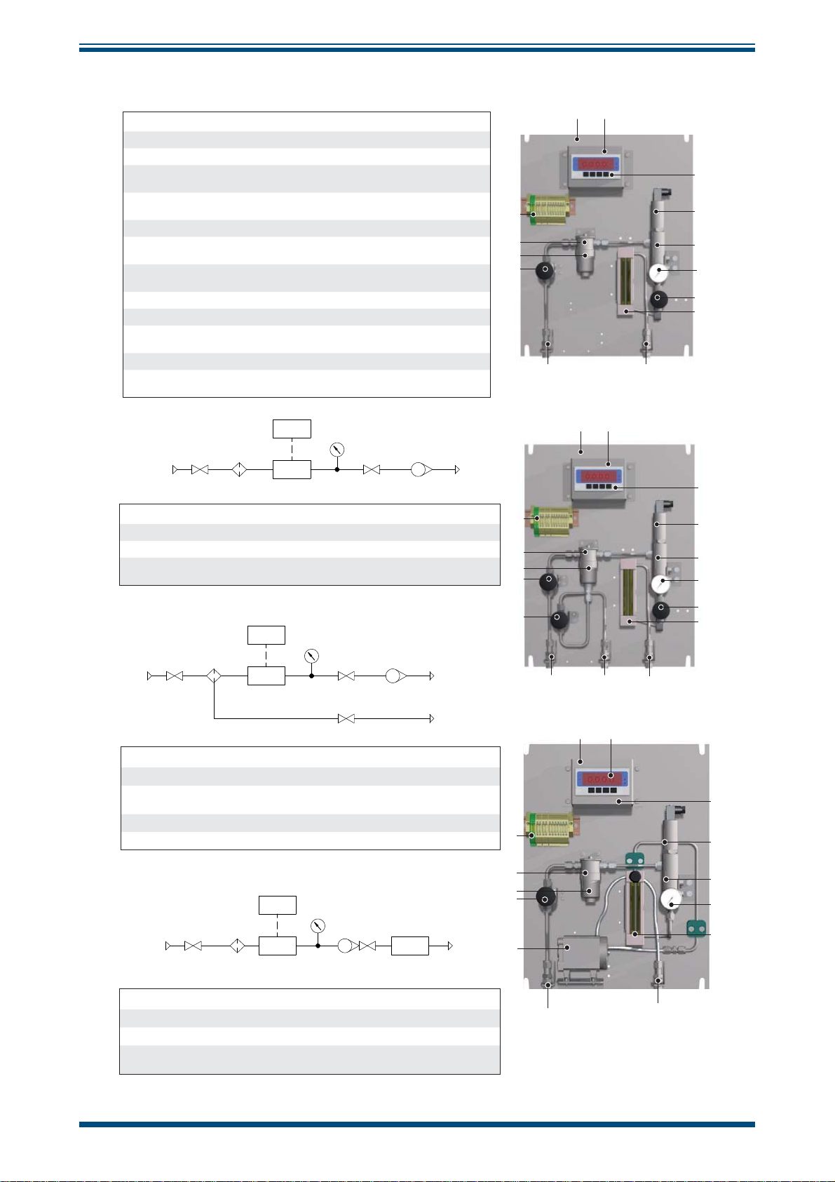
ES20 CSS fi tted with Particulate Filter
Components used Specifi cations
1 Base plate 316 stainless steel
Inlet process connection and
2
material
Outlet process connection and
3
material
6mm or ¼” fi tting (316 stainless steel)
6mm or ¼” fi tting (316 stainless steel)
4 Isolation valve Needle valve type
5 Filter housing
Particulate fi lter (inside fi lter
6
housing)
316 stainless steel (340 barg maximum),
gasket (Viton
Borosilicate glass microfi bres (99.5+% removal
of 0.1 micron particles)
®
)
7 Pressure gauge 0 to 20 barg (dual scale: bar and psi)
8 Sensor sample block 5/8” SS sample block (316 stainless steel)
9 Flowmeter
Borosilicate glass (2 to 12 Nl/min), seals
®
)
(Viton
10 Terminal rail 13 terminals
Process indicator mounting bracket
11
*$6,1/(7
(optional)
1(('/(
9$/9(
3$57,&8/$7(
),/7(5
($6,'(:
021,725
($6,'(:
6(1625
1/8 DIN cutout
35(6685(
*$8*(
1(('/(
9$/9(
)/2:0(7(5
ES20 CSS fi tted with Coalescing Filter*
Components used Specifi cations
12 Drainage connection 6mm or ¼” fi tting (316 stainless steel)
13 Coalescing fi lter (inside fi lter housing)
*In addition to particulate fi lter fi tted components
($6,'(:
021,725
&2$/(6&,1*
*$6,1/(7
1(('/(
9$/9(
),/7(5
($6,'(:
6(1625
Borosilicate glass microfi bres (99.5+% removal
of 0.1 micron particles and aerosols)
1(('/(
)/2:0(7(5
9$/9(
1(('/(
9$/9(
*$6
287/(7
%<3$66
287/(7
*$6
287/(7
10
5
6
4
2
10
5
13
4
4
212
111
17**
18**
8
7
4
9
3
111
17**
18**
8
7
4
9
3
111
ES20 CSS fi tted with Vacuum Pump*
Components used Specifi cations
14 Flowmeter with needle valve
15 Vacuum pump Anti-overpressure mechanism (Tefl on
16 Pressure gauge -1 to 1 barg
*In addition to particulate fi lter fi tted components
($6,'(:
021,725
3$57,&8/$7(
*$6,1/(7
1(('/(
9$/9(
),/7(5
($6,'(:
6(1625
Optional Dew-Point Measurement Device
Components used Specifi cations
17 Monitor
18
(to be ordered separately)**
Dew-Point Transmitter
ordered separately)**
(to be
Borosilicate glass (2 to 12 Nl/min), seals
®
(Viton
)
35(6685(
*$8*(
)/2:0(7(5
$1'9$/9(
9$&880
3803
Refer to Monitor datasheet
Refer to Transmitter datasheet
®
)
*$6
287/(7
17**
10
5
6
4
18**
8
16
14
15
2
3
2 97447 Issue 2, December 2017
Page 11
ES20 User’s Manual
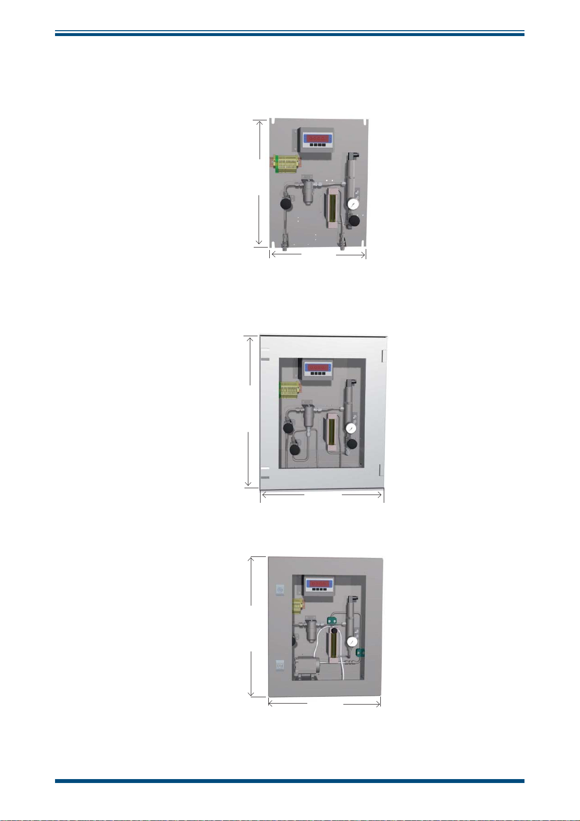
1.8 Enclosure Confi gurations
INTRODUCTION
Base Plate
457mm
350mm
2mm (D)
GRP Enclosure
530mm
430mm
200mm (D)
Stainless Steel Enclosure
500mm
400mm
200mm (D)
Michell Instruments 3
Page 12

INSTALLATION
2 INSTALLATION
2.1 Sampling System Installation
It is essential that the connection of electrical and gas supplies
to this instrument be undertaken by competent personnel.
Relevant sections of this manual must be read in full before
commencing measurement (see below).
ES20 User’s Manual
2.1.1 Relevant Manual Section for Installation
Please check below for the relevant product code structure and select the manual
section associated with the sampling system ordered.
NOTE: Compare the 2nd (Feature B - fi lter) and 4th (Feature D - pressure)
option from the ordered ES20 CSS product code with the table below:
Section 2.2 Section 2.3 Section 2.4
B1 - D1
Process or Atmospheric
Pressure
Process or Atmospheric
B2 - D1
Pressure
B1 - D2
Vacuum
Pressure
4 97447 Issue 2, December 2017
Page 13

ES20 User’s Manual
2.2 Process or Atmospheric Pressure With Particulate Filter
NOTE: All other options from the product confi guration have no effect on the
operation described in this Section.
2.2.1 Mounting Details
The ES20 CSS base plate or enclosure is designed to be wall-mounted. It should be
rigidly mounted vertically in a position free from high vibration levels and shaded from
direct sunlight.
Dimensional drawings are shown in Section 1.8.
2.2.2 Gas Connections
Gas connections to the ES20 CSS are via 6mm or ¼” Swagelok® tube fi ttings located at
the base of the mounting plate or enclosure.
INSTALLATION
Connections are marked as follows:
GAS IN
GAS OUT
2.2.3 Electrical Connections
All electrical connections should be made to the terminal rail supplied in the sampling
system.
For GRP and SS housing versions - all cables to or from the sampling system should go
through the M20 plastic cable glands provided at the base of the enclosure.
Sample gas entry point with a maximum supply pressure of 20 barg
(145 psig)
Sample gas exit point
Care must be taken to ensure that the outlet isolation valve is
not fully closed.
2.2.4 Power Supply
NOTE: Refer to the label on the terminal rail for the supply voltage required
by the sampling system.
Go to Section 2.5 - Dew-Point Measurement System.
Michell Instruments 5
Page 14

INSTALLATION
ES20 User’s Manual
2.3 Process or Atmospheric Pressure With Coalescing Filter
NOTE: All other options from the product confi guration have no effect on the
operation described in this Section.
2.3.1 Mounting Details
The ES20 CSS base plate or enclosure is designed to be wall-mounted. It should be
rigidly mounted vertically in a position free from high vibration levels and shaded from
direct sunlight.
Dimensional drawings are shown in Section 1.8.
2.3.2 Gas Connections
Gas connections to the ES20 CSS are via 6mm or ¼” Swagelok® tube fi ttings located at
the base of the mounting plate or enclosure.
Connections are marked as follows:
GAS IN
GAS OUT
2.3.3 Drainage Connections
Drainage connections to the ES20 CSS are via 6mm or ¼” Swagelok® tube fi ttings
located at the base of the mounting plate or enclosure.
2.3.4 Electrical Connections
Sample gas entry point with a maximum supply pressure of 20 barg
(145 psig)
Sample gas exit point
Care must be taken to ensure that the outlet isolation valve is
not fully closed.
All electrical connections should be made to the terminal rail supplied in the sampling
system.
For GRP and SS housing versions - all cables to or from the sampling system should go
through the M20 plastic cable glands provided at the base of the enclosure.
2.3.5 Power Supply
NOTE: Refer to the label on the terminal rail for the supply voltage required
by the sampling system.
Go to Section 2.5 - Dew-Point Measurement System.
6 97447 Issue 2, December 2017
Page 15
ES20 User’s Manual
2.4 Vacuum Pressure With Particulate Filter
NOTE: All other options from the product confi guration have no effect on the
operation described in this Section.
2.4.1 Mounting Details
The ES20 CSS base plate or enclosure is designed to be wall-mounted. It should be
rigidly mounted vertically in a position free from high vibration levels and shaded from
direct sunlight.
Dimensional drawings are shown in Section 1.8.
2.4.2 Gas Connections
Gas connections to the ES20 CSS enclosure are via 6mm or ¼” Swagelok® tube fi ttings
located at the base of the mounting plate or enclosure.
INSTALLATION
Connections are marked as follows:
GAS IN
GAS OUT
2.4.3 Electrical Connections
All electrical connections should be made to the terminal rail supplied in the sampling
system.
For GRP and SS housing versions - all cables to or from the sampling system should go
through the M20 plastic cable glands provided at the base of the enclosure.
Sample gas entry point with a maximum supply pressure of 1 bara (14.5
psia)
Sample gas exit point
Care must be taken to ensure that the outlet isolation valve is
fully open.
2.4.4 Power Supply
NOTE: Refer to the label on the terminal rail for the supply voltage required
by the sampling system.
Go to Section 2.5 - Dew-Point Measurement System.
Michell Instruments 7
Page 16

INSTALLATION
The following procedures must be carried out by a qualifi ed
2.5 Dew-Point Measurement System
The dew-point measurement system is NOT supplied as standard.
A dew-point measurement system can be obtained by contacting your local distributor
or Michell Instruments (see www.michell.com for details).
NOTE: Refer to the relevant installation sections from the manual supplied
with Michell’s dew-point measurement system.
ES20 User’s Manual
installation engineer.
2.6 Monitor Installation
The monitor is NOT supplied as standard.
A monitor can be obtained by contacting your local distributor or Michell Instruments
(see www.michell.com for details).
NOTE: Refer to the relevant sections from the manual supplied with Michell’s
monitor.
8 97447 Issue 2, December 2017
Page 17
ES20 User’s Manual
2.7 Process Connection
The following procedures must be carried out by a qualifi ed
2.7.1 Transmitter Connection
The transmitter cable is NOT supplied as standard.
A cable can be obtained by contacting your local distributor or Michell Instruments (see
www.michell.com for details).
NOTE: Please refer to the relevant sections from the manual supplied with
Michell’s product, e.g. Easidew Online.
INSTALLATION
installation engineer.
2.7.2 Monitor Connection
Note: Please refer to the relevant sections from the manual supplied with
Michell’s product, e.g. Easidew Online or Easidew monitor.
2.7.3 Terminal Rail Connection
The transmitter cable can be directly connected to the terminal rail. In order to do that,
refer to terminal markings.
Make sure that the correct power supply is provided, otherwise
The transmitter requires a 12 to 28 V supply.
the transmitter can be damaged.
Michell Instruments 9
Page 18
OPERATION
3 OPERATION
3.1 Sampling Start-Up Procedure
The ES20 CSS is designed for continuous operation.
Immediately after the power is applied, all the electronic components, including the
dew-point transmitter, will begin operation and all measured output signals can be
viewed on a fi tted monitor or wired to other receivers from the terminal rail.
It is essential that the connection of electrical and gas supplies
to this instrument be undertaken by competent personnel.
Relevant sections of this manual must be read in full before
commencing measurement (see below).
ES20 User’s Manual
3.1.1 Relevant Manual Section for Operation
Please check below for the relevant product code structure and select the manual
section associated with the sampling system ordered.
NOTE: Compare the 2nd (Feature B - fi lter) and 4th (Feature D - pressure)
option from the ordered ES20 CSS product code with the table below:
Section 3.2 Section 3.3 Section 3.4 Section 3.5 Section 3.6
B1 - D1
Process Pressure
with Particulate
Filter
B2 - D1
Process Pressure
with Coalescing
Filter
B1 - D1
Atmospheric
Pressure with
Particulate Filter
B2 - D1
Atmospheric
Pressure with
Coalescing Filter
B1 - D2
Vacuum Pressure
with Particulate
Filter
10 97447 Issue 2, December 2017
Page 19

ES20 User’s Manual
3.2 Process Pressure With Particulate Filter
NOTE: All other options from the product confi guration have no effect on the
operation described in this Section.
3.2.1 Sample Flow 'Start-Up' Procedure
Proceed as follows:
OPERATION
1. Ensure the outlet isolation valve is fully
2. Open the inlet isolation valve slowly, making sure that the pressure
indicated on the pressure gauge does not exceed the maximum
operational pressure of 20 barg (290 psig). If achievable, ensure that the
inlet isolation valve is fully
3. Adjust the outlet isolation valve, setting the sample gas fl ow rate to
approximately 5 Nl/min (10.6 scfh) (indicated on the fl owmeter).
4. Allow the sample gas to purge the system for the period of time indicated
in the Good Measurement Practice Section (Stabilization Times).
OPEN.
3.3 Process Pressure with Coalescing Filter
NOTE: All other options from the product confi guration have no effect on the
operation described in this Section.
3.3.1 Sample Flow 'Start-Up' Procedure
CLOSED.
Proceed as follows:
1. Ensure the outlet and drain isolation valves are fully
2. Open the inlet isolation valve slowly, making sure that the pressure
indicated on the pressure gauge does not exceed the maximum
operational pressure of 20 barg (290 psig). If achievable, ensure that the
inlet isolation valve is fully
3. Adjust the outlet isolation valve, setting the sample gas fl ow rate to
approximately 5 Nl/min (10.6 scfh) (indicated on the fl owmeter).
4. If necessary adjust the drain isolation valve to release excessive amount
of liquids from the fi lter housing.
NOTE: If required the drain isolation valve can be slightly
may be necessary to adjust the inlet and outlet isolation valves to
achieve normal operating conditions.
5. Allow the sample gas to purge the system for the period of time indicated
in the Good Measurement Practice Section (Stabilization Times).
OPEN.
CLOSED.
OPEN. It
Michell Instruments 11
Page 20

OPERATION
3.4 Atmospheric Pressure with Particulate Filter
NOTE: All other options from the product confi guration have no effect on the
operation described in this Section.
3.4.1 Sample Flow 'Start-Up' Procedure
Proceed as follows:
ES20 User’s Manual
1. Ensure the outlet isolation valve is fully
2. Open the inlet isolation valve making sure that the sample gas fl ow rate
is set to approximately 5 Nl/min (10.6 scfh) (indicated on the fl owmeter).
3. Allow the sample gas to purge the system for the period of time indicated
in the Good Measurement Practice Section (Stabilization Times).
OPEN.
3.5 Atmospheric Pressure with Coalescing Filter
NOTE: All other options from the product confi guration have no effect on the
operation described in this Section.
3.5.1 Sample Flow 'Start-Up' Procedure
Proceed as follows:
1. Ensure the outlet is fully
2. Open the inlet isolation valve making sure that the sample gas fl ow rate
is set to approximately 5 Nl/min (10.6 scfh) (indicated on the fl owmeter).
OPEN and drain isolation valves are fully CLOSED.
3. If necessary adjust the drain isolation valve to release excessive amount
of liquids from the fi lter housing.
NOTE: After adjusting the drain isolation valve it may be necessary
to adjust the inlet valve to achieve normal operating conditions
4. Allow the sample gas to purge the system for the period of time indicated
in the Good Measurement Practice Section (Stabilization Times).
12 97447 Issue 2, December 2017
Page 21

ES20 User’s Manual
3.6 Vacuum Pressure With Particulate Filter
NOTE: All other options from the product confi guration have no effect on the
operation described in this Section.
3.6.1 Sample Flow 'Start-Up' Procedure
Proceed as follows:
1. Ensure that the control valve located on the top of the fl owmeter is
fully OPEN by turning fully counter-clockwise (valve is designed for fl ow
adjustment only, not intended to be used as a shut-off valve).
2. Slowly open the inlet isolation valve making sure that pressure indicated
on the pressure gauge is within -0.33 barg (-4.7 psig) and 0 barg (0 psig).
If achievable, ensure that the inlet isolation valve is fully
Note: Ensure that the pressure indicated on the pressure gauge is
showing a vacuum and that the fl owmeter is not operating. If this
is not the case DO NOT switch on the pump.
OPERATION
OPEN.
3. Set the valve on the fl owmeter to half way (clockwise to
on the pump by turning on the power to it. This will allow the sample gas
to fl ow through the system.
4. By adjusting the control valve located on the fl owmeter, set the sample
gas fl ow rate to approximately 5 Nl/min (10.6 scfh).
5. Allow the sample gas to purge the system for the period of time indicated
in the Good Measurement Practice Section (Stabilization Times).
CLOSE). Switch
Michell Instruments 13
Page 22

MAINTENANCE
4 MAINTENANCE
4.1 General Maintenance Guidelines
Routine maintenance of the sampling system is confi ned to fi lter element replacement
and regular recalibration of the dew-point transmitter.
4.2 Filter Element Maintenance
The composition of the gas determines the frequency of the fi lter element replacement,
i.e. liquid and particulate contaminates, corrosive elements etc.
A disposable fi lter element continues to fi lter at its original effi ciency as long as it is
kept in service. The life of the element is determined by the increase in fl ow resistance
caused by trapped solids in the element. The element should be changed when the fl ow
falls below an acceptable level, or the pressure drop becomes too high. In any case the
element should be replaced before the pressure drop across it reaches 0.7 barg (10.2
psig). The disposable fi lter elements cannot be cleaned as the solids are trapped within
the depth of the element not on the surface.
ES20 User’s Manual
4.2.1 Particulate Filter Maintenance
To replace the particulate fi lter element (Michell part SSF-PF-10PK (pack of 10)), proceed
as follows:
1. Switch off the pump (if fi tted) and isolate any gas supplies to the sampling
system.
NOTE: Wear protective gloves when handling the fi lter housing.
2.
Remove the bowl (1,2), element retainer (3) and fi lter element (4).
NOTE: In order to untighten the bowl a spanner/wrench may be
needed.
Disposable and sintered PTFE fi lter elements are sealed by compression
against a fl at surface (5). Gaskets are not required between the fi lter element
and components of the housing. The element is located by guides which fi t
the inside diameter of the tube at each end.
14 97447 Issue 2, December 2017
Page 23

ES20 User’s Manual
The fi lter tube is securely sealed by tightening the element retainer a 1/4 to
1 turn after it fi rst contacts the fi lter element, the amount will depend on the
housing type and element size. A mark on the end of the retainer is used as
a guide.
3. Before replacing the housing bowl ensure that the mating threads and
sealing faces are clean and damage free. It is recommended that the
threads and sealing faces are lubricated with a small amount of silicone
grease before assembly.
MAINTENANCE
4. Re-connect the tube with its fi tting to its original confi guration.
5. Resume normal system operation by opening up the gas supplies to the
sampling system as described in the relevant section of the Start-up
Procedures (Section 3).
Michell Instruments 15
Page 24

MAINTENANCE
4.2.2 Coalescing Filter Maintenance
To replace the coalescing fi lter element (Michell part SSF-CF-10PK (pack of 10)), proceed
as follows:
1. Isolate any gas supplies to the sampling system.
NOTE: Wear protective gloves when handling the fi lter housing.
2. Unscrew the couplings (1 and 2) on the picture below.
1
2
3
ES20 User’s Manual
3. Disconnect the tube with its fi tting (3).
4.
Remove the bowl (1,2), element retainer (3) and fi lter element (4).
NOTE: In order to untighten the bowl a spanner/wrench may be
needed.
Disposable and sintered PTFE fi lter elements are sealed by compression
against a fl at surface (5). Gaskets are not required between the fi lter element
and components of the housing. The element is located by guides which fi t
the inside diameter of the tube at each end.
16 97447 Issue 2, December 2017
Page 25

ES20 User’s Manual
The fi lter tube is securely sealed by tightening the element retainer a 1/4 to
1 turn after it fi rst contacts the fi lter element, the amount will depend on the
housing type and element size. A mark on the end of the retainer is used as
a guide.
5. Before replacing the housing bowl ensure that the mating threads and
sealing faces are clean and damage free. It is recommended that the
threads and sealing faces are lubricated with a small amount of silicone
grease before assembly.
6.
MAINTENANCE
Re-connect the tube with its fi tting to its original confi guration.
7. Resume normal system operation by opening up the gas supplies to the
sampling system as described in the relevant section of the Start-up
Procedures (Section 3).
Michell Instruments 17
Page 26

MAINTENANCE
4.3 Transmitter Maintenance
Calibration
Routine maintenance of the Easidew transmitter is confi ned to regular re-calibration
by exposure of the Easidew to sample gases of known moisture content to ensure that
the stated accuracy of the Easidew is maintained. Calibration services traceable to the
UK National Physical Laboratory (NPL) and the US National Institute of Standards and
Technology (NIST) are provided by Michell Instruments.
Michell Instruments offers a variety of re-calibration and exchange sensor schemes to
suit specifi c needs. A Michell representative can provide detailed, custom advice (for
Michell Instruments’ contact information go to www.michell.com).
Transmitter replacement
The composition of the gas determines the frequency of the transmitter replacement,
i.e. liquid and particulate contaminates, corrosive elements, etc.
ES20 User’s Manual
It is recommended that the transmitter is changed on an annual basis to maintain the
accuracy of the system.
Michell Instruments can provide an exchange transmitter. Prior to recalibration being
necessary, an exchange transmitter can be ordered from Michell Instruments or any
authorized dealer. Once the transmitter and calibration certifi cate have been received it
can be fi tted and the original transmitter returned to Michell Instruments.
To replace the transmitter, proceed as follows:
1. Isolate the sampling system from the sample gas supply and switch off
all electrical supplies.
2. Unplug the sensor cable, unscrew and withdraw the sensor from the
sample block.
3. Fit a new/recalibrated transmitter ensuring the bonded seal is positioned
between the sensor and sample block.
4. Plug in the sensor cable and resume normal system operation by opening
up the gas supplies to the sampling system in accordance with the relevant
section of the Start-up Procedures (Section 3).
18 97447 Issue 2, December 2017
Page 27
ES20 User’s Manual
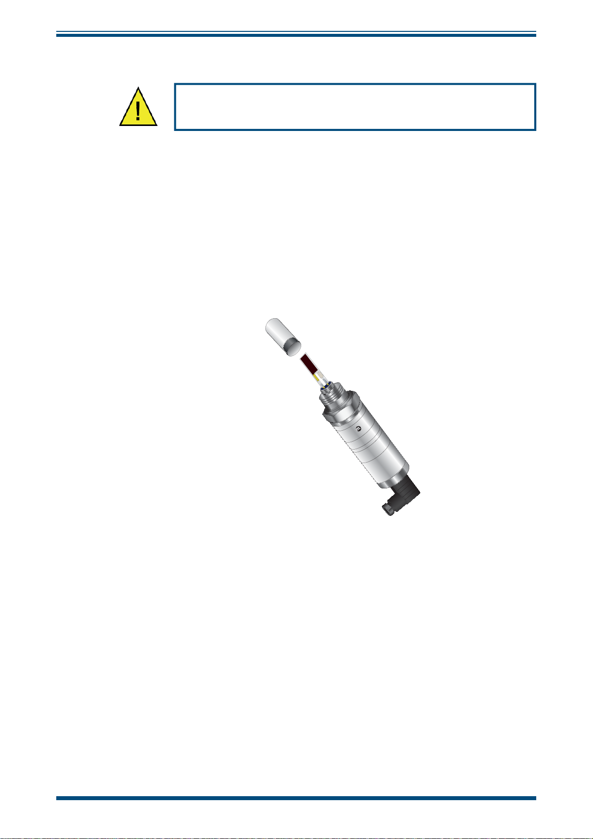
Sensor Guard Replacement
The sensor is supplied with a white HDPE guard (standard) or a stainless steel guard
(if specifi ed at time or order). The method of replacement is the same for both types.
HDPE Guard
The HDPE guard provides <10μm protection to the dew-point sensor. It is designed
to show any contamination and the guard should be changed if the surface becomes
discolored. When replacing the guard, care should be taken to handle the guard by the
bottom part only. Replacement guards (EA2-HDPE) - pack of 10 - can be obtained by
contacting Michell Instruments (www.michell.com) or your local distributor.
MAINTENANCE
Wear protective gloves when handling the sensor guard.
HANDLE,
USING
GLOVES, BY
x
BLACK PART
ONLY
E
n
e
H
m
C
u
I
r
6
t
s
0
M
n
9
I
0
Figure 1
Replacement of HDPE Guard
r
e
t
t
i
m
s
0
n
2
a
+
r
/
T
B
4
0
y
3
0
a
s
1
w
e
W
-
e
g
d
r
:
i
s
a
E
R
N
d
e
e
i
t
3
r
g
s
b
n
a
6
a
c
g
m
B
n
a
n
a
i
C
C
L
K
,
8
y
l
4
d
E
e
t
i
n
U
Stainless Steel Guard
The stainless steel guard provides <80μm protection to the dew-point sensor. It is
designed to show any contamination and the guard should be changed if the surface
becomes discolored.
When replacing the guard, care should be taken to handle the guard by the bottom part
only. A replacement guard (SSG) can be obtained by contacting Michell Instruments
(www.michell.com) or your local distributor.
Bonded Seal
If the installed bonded seal gets damaged or lost, a pack of 5 replacement bonded seals
can be obtained by contacting Michell Instruments, or your local distributor, and quoting
part number BS-58-PK5.
Michell Instruments 19
Page 28

APPENDIX A
ES20 User’s Manual
Appendix A
Technical Specifi cations
20 97447 Issue 2, December 2017
Page 29
ES20 User’s Manual
Appendix A Technical Specifi cations
Electrical Specifi cations
Supply Voltage (Vacuum Pump Only) 230 V AC
Operating Specifi cations
Operating Temperature
ES20 fi tted with:
Particulate or coalescing fi lter w/out monitor
Particulate or coalescing fi lter with monitor
Vacuum pump with or w/out monitor
Compensated Temperature Range:
Storage Temperature: -40 to +60°C (-40 to +140°F)
Operating Inlet Pressure
ES20 fi tted with:
Particulate Filter
Coalescing Filter
Vacuum Pump
Flow Rate 1 to 5 Nl/min (2.1 to 10.6 scfh)
-40 to +60°C (-40 to +140°F)
0 to +50°C (+32 to +122°F)
0 to +40°C (+32 to +104°F)
-20 to +50°C (-4 to +122°F)
NOTE: The transmitter accuracy statement is only valid for
the temperature range: -20/+50°C (-4 to +122°F)
0 to 20 barg (0 to 290 psig)
0 to 20 barg (0 to 290 psig)
-0.3 to 1 barg (-4.7 to 14.5 psig)
APPENDIX A
Mechanical Specifi cations
Process Connection and Material
Ingress Protection
No enclosure
GRP & SS enclosures
Housing Material
Base plate
GRP enclosure
SS enclosures
Dimensions
Base plate
GRP enclosure
SS enclosures
Pressure and Flow Control
Atmospheric or system pressure
Vacuum pressure
Gas Filtration
Electrical Connections
Base plate
GRP & SS enclosures
Interchangeability Fully interchangeable components
Sample Block Process Connection
Inlet/outlet connections via 6mm or ¼” stainless steel
fi ttings, 316 stainless steel
No protection (base plate only)
IP66, NEMA 4X
316 stainless steel
Glass fi ber reinforced polyester and 4mm safety glass
316 stainless steel and 4mm safety glass
457 x 350 x 2mm (18 x 13.8 x .08") (hxwxd)
530 x 430 x 200mm (20.9 x 16.9 x 7.9") (hxwxd)
500 x 400 x 200mm (19.7 x 15.7 x 7.9") (hxwxd)
Via isolation valves, pressure gauge and fl owmeter
Isolation valve, pressure gauge, fl owmeter with valve &
self-regulating vacuum pump
Particulate fi lter
Coalescing fi lter
Via terminal rail
Via M20 plastic cable glands
Compatible with various dew-point transmitters with
5/8" process connection
Compatible Dew-Point Transmitters (5/8" UNF process connection versions only):
• Easidew Transmitter
• Easidew I.S. Transmitter
• Easidew PRO I.S. Transmitter
Michell Instruments 21
Page 30

APPENDIX B
ES20 User’s Manual
Appendix B
Quality, Recycling
& Warranty
Information
22 97447 Issue 2, December 2017
Page 31

ES20 User’s Manual
Appendix B Quality, Recycling & Warranty Information
Michell Instruments is dedicated to complying to all relevant legislation and directives.
Full information can be found on our website at:
www.michell.com/compliance
This page contains information on the following directives:
• ATEX Directive
• Calibration Facilities
• Confl ict Minerals
• FCC Statement
• Manufacturing Quality
• Modern Slavery Statement
APPENDIX B
• Pressure Equipment Directive
• REACH
• RoHS2
• WEEE2
• Recycling Policy
• Warranty and Returns
This information is also available in PDF format.
Michell Instruments 23
Page 32

APPENDIX C
ES20 User’s Manual
Appendix C
Return Document
&
Decontamination Declaration
24 97447 Issue 2, December 2017
Page 33

ES20 User’s Manual
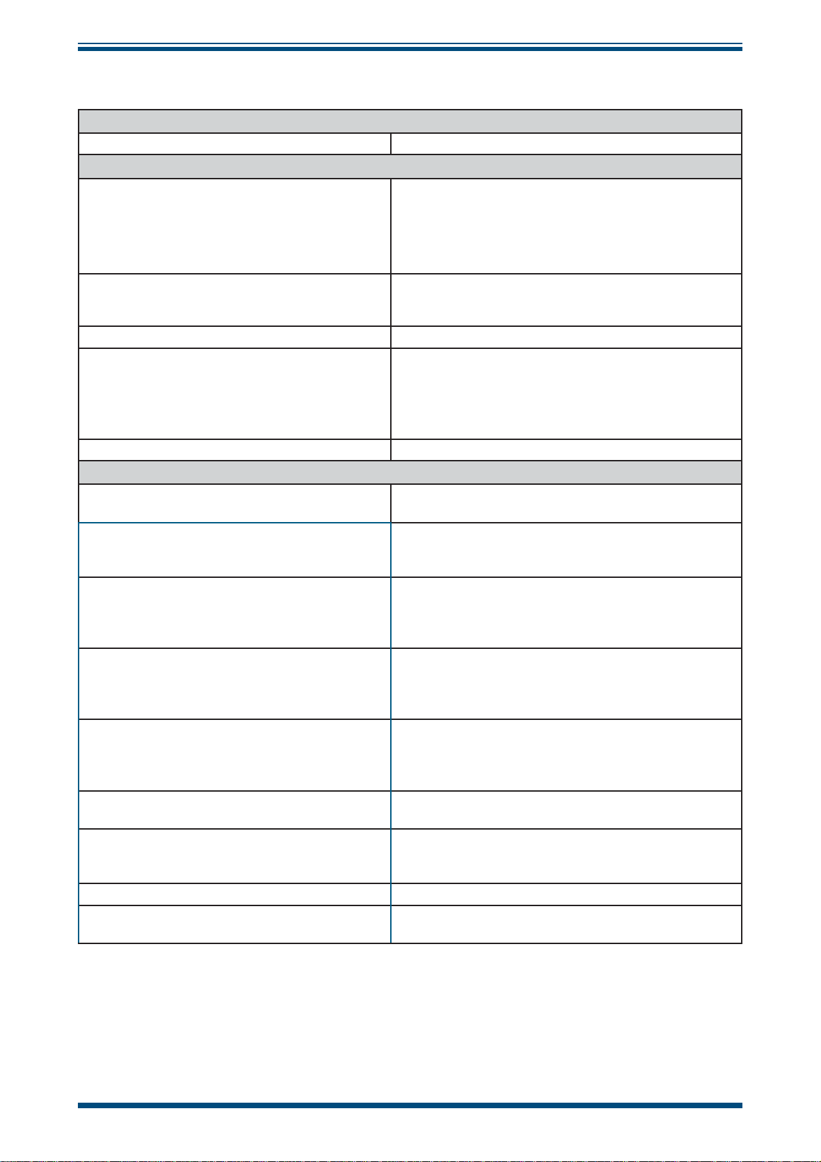
Appendix C Return Document & Decontamination Declaration
'HFRQWDPLQDWLRQ&HUWL¿FDWH
IMPORTANT NOTE: Please complete this form prior to this instrument, or any components, leaving your
site and being returned to us, or, where applicable, prior to any work being carried out by a Michell
engineer at your site.
Instrument Serial Number
Warranty Repair? YES NO Original PO #
Company Name Contact Name
Address
Telephone # E-mail address
Reason for Return /Description of Fault:
APPENDIX C
Has this equipment been exposed (internally or externally) to any of the following?
Please circle (YES/NO) as applicable and provide details below
Biohazards YES NO
Biological agents YES NO
Hazardous chemicals YES NO
Radioactive substances YES NO
Other hazards YES NO
Please provide details of any hazardous materials used with this equipment as indicated above (use continuation sheet
if necessary)
Your method of cleaning/decontamination
Has the equipment been cleaned and decontaminated? YES NOT NECESSARY
Michell Instruments will not accept instruments that have been exposed to toxins, radio-activity or bio-hazardous
PDWHULDOV)RUPRVWDSSOLFDWLRQVLQYROYLQJVROYHQWVDFLGLF EDVLFÀDPPDEOHRUWR[LFJDVHVDVLPSOHSXUJHZLWK GU\
JDVGHZSRLQW&RYHUKRXUVVKRXOGEHVXI¿FLHQWWRGHFRQWDPLQDWHWKHXQLWSULRUWRUHWXUQ
Work will not be carried out on any unit that does not have a completed decontamination declaration.
Decontamination Declaration
I declare that the information above is true and complete to the best of my knowledge, and it is safe for Michell
personnel to service or repair the returned instrument.
Name (Print) Position
Signature Date
F0121, Issue 2, December 2011
Michell Instruments 25
Page 34

NOTES:
Page 35

Page 36

http://www.michell.com
 Loading...