

Page 1

Intrinsically Safe Field Display
User Manual
ppm
V
Easidew PRO I.S. Field Display
E
P
97321 Issue 3.1
September 2021
Page 2

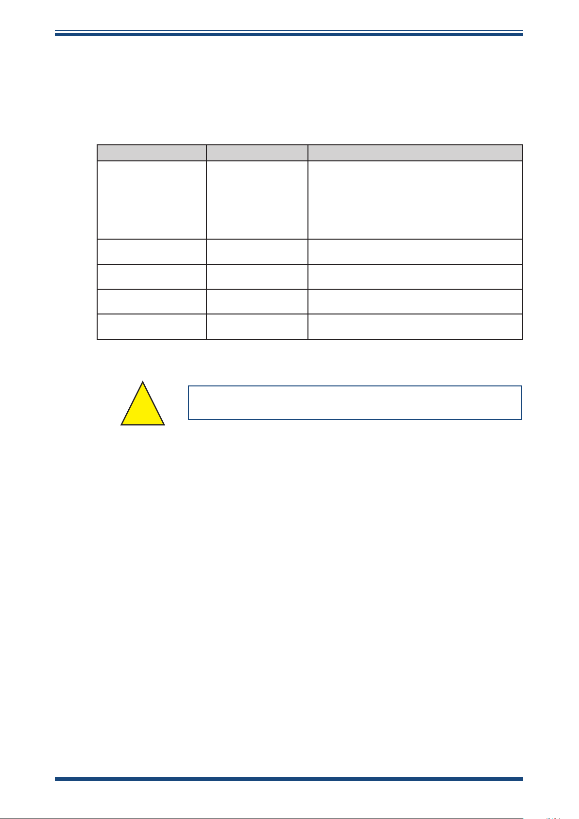
Please ll out the form(s) below for each instrument that has been purchased.
Use this information when contacting Michell Instruments for service purposes.
Product Name
Order Code
Serial Number
Invoice Date
Installation Location
Tag Number
Product Name
Order Code
Serial Number
Invoice Date
Installation Location
Tag Number
Product Name
Order Code
Serial Number
Invoice Date
Installation Location
Tag Number
Page 3

I.S. Field Display
For Michell Instruments' contact information please go to
www.michell.com
© 2021 Michell Instruments
This document is the property of Michell Instruments Ltd and may not be copied or
otherwise reproduced, communicated in any way to third parties, nor stored in any Data
Processing System without the express written authorization of Michell Instruments Ltd.
Page 4

I.S. Field Display User Manual
Contents
Safety ................................................................................................................................vi
Toxic Materials .............................................................................................................vi
Repair and Maintenance ...............................................................................................vi
Safety Conformity ........................................................................................................vi
Abbreviations ......................................................................................................................vi
Warnings ............................................................................................................................vi
1 INTRODUCTION ................................................................................................1
1.1 Operation ......................................................................................................... 1
1.1.1 Controls ....................................................................................................... 2
2 INSTALLATION ..................................................................................................3
2.1 4...20 mA Input ............................................................................................... 3
2.2 System Design for Gas Hazardous Areas ............................................................. 4
2.2.1 Transmitter Loops ......................................................................................... 4
2.2.2 Remote Indication ......................................................................................... 5
2.3 Location ........................................................................................................... 6
2.4 Installation Procedure ....................................................................................... 6
2.5 EMC ................................................................................................................ 7
3 OPERATION ......................................................................................................8
3.1 Conguration And Calibration ............................................................................. 8
3.1.1 Summary of Conguration Functions .............................................................. 9
3.1.2 Indicator Function: ‘FunC’ ........................................................................... 11
3.1.2.1 ‘Std’ Linear (Default) ............................................................................ 12
3.1.3 Resolution: 'rESn'....................................................................................... 12
3.1.4 Position of the Decimal Point: ‘dP’ ............................................................... 12
3.1.5 Re-Range Display or Calibrate Using an External Current Source: ‘CAL’ .......... 13
3.1.6 Re-Range Display or Calibrate Using Internal Reference: ‘SEt’ ....................... 14
3.1.7 Function of the P Push-Button: ‘C - - P’ ........................................................ 14
3.1.8 Tare Function: ‘tArE’ .................................................................................. 15
3.1.9 Security Code: ‘CodE’ ................................................................................. 15
3.1.10 Reset to Factory Defaults: ‘rSEt’ .................................................................. 15
3.1.11 Under and Over-Range ................................................................................ 16
3.2 External Keypad (Optional) .............................................................................. 16
3.3 Alarms (Optional) ............................................................................................ 17
3.3.1 Solid State Output ...................................................................................... 18
3.3.2 Intrinsic Safety............................................................................................ 18
3.3.3 Conguration and Adjustment ...................................................................... 19
3.3.4 Alarm Enable: ‘EnbL’ .................................................................................. 20
3.3.5 Setpoint Adjustment: ‘SP1’ and ‘SP2’........................................................... 20
3.3.6 Alarm Function: ‘Hi.Lo’ ............................................................................... 21
3.3.7 Alarm Output Status: ‘no.nC’ ...................................................................... 21
3.3.8 Hysteresis: 'HStr' ....................................................................................... 21
3.3.9 Alarm Delay: 'dELA' ................................................................................... 22
3.3.10 Alarm Silence Time: 'SiL' ............................................................................ 22
3.3.11 Flash Display when Alarm Occurs: ‘FLSH’..................................................... 23
3.3.12 Access Setpoint in Display Mode: 'ACSP' ...................................................... 23
3.3.13 Adjusting Alarm Setpoints from the Display Mode .......................................... 24
3.4 Display Backlight (Optional) ............................................................................. 25
3.4.1 Loop Powering the Backlight ........................................................................ 25
3.4.2 Separately Powering the Backlight ................................................................ 26
3.5 Pipe-Mounting Kits .......................................................................................... 27
iv 97321 Issue 3.1, September 2021
Page 5

I.S. Field Display User Manual
4 MAINTENANCE ................................................................................................28
4.1 Fault Finding During Commissioning ................................................................. 28
4.2 Fault Finding After Commissioning .................................................................... 28
4.3 Servicing ........................................................................................................ 28
4.4 Routine Maintenance ....................................................................................... 28
Figures
Figure 1 Indicator Block Diagram ..............................................................................2
Figure 2 Loop-Powered by a Galvanic Isolator (Easidew PRO I.S.) ...............................4
Figure 3 Loop-Powered by a Galvanic Isolator (Easidew TX I.S.) .................................4
Figure 4 Alternative Circuits for Remote Indication in a Hazardous Area ......................5
Figure 5 Installation Procedure .................................................................................6
Figure 6 Dimensions & Terminal Connections .............................................................7
Figure 7 Conguration Menu ..................................................................................10
Figure 8 Alarm Outputs ..........................................................................................17
Figure 9 Equivalent Circuit of Each Alarm Output .....................................................18
Figure 10 Typical Alarm Application ..........................................................................18
Figure 11 Alarm Conguration Functions in Conguration Menu ..................................19
Figure 12 Terminals for Optional Backlight ................................................................25
Figure 13 Loop-Powered Backlight ............................................................................25
Figure 14 Separately Powered Backlight ....................................................................26
Figure 15 Pipe-Mounting Kit .....................................................................................27
Appendices
Appendix A Hazardous Area Certication ......................................................................30
A.1 ATEX Certication ........................................................................30
A.2 Product Standards .......................................................................30
A.3 Product Certication ....................................................................30
A.4 Global Certicates/Approvals ........................................................31
A.5 Input Terminal Parameters ...........................................................31
A.6 Special Conditions........................................................................31
A.7 Non- Incendive ............................................................................31
A.8 Maintenance and Installation ........................................................31
Appendix B Quality, Recycling & Warranty Information ................................................... 43
Appendix C Return Document & Decontamination Declaration ........................................ 45
Michell Instruments v
Page 6

I.S. Field Display User Manual
!
Safety
The manufacturer has designed this equipment to be safe when operated using the procedures
detailed in this manual. The user must not use this equipment for any other purpose than that
stated. Do not apply values greater than the maximum value stated.
This manual contains operating and safety instructions, which must be followed to ensure the safe
operation and to maintain the equipment in a safe condition. The safety instructions are either
warnings or cautions issued to protect the user and the equipment from injury or damage. Use
qualied personnel and good engineering practice for all procedures in this manual.
Toxic Materials
The use of hazardous materials in the construction of this instrument has been minimized. During
normal operation it is not possible for the user to come into contact with any hazardous substance
which might be employed in the construction of the instrument. Care should, however, be exercised
during maintenance and the disposal of certain parts.
Repair and Maintenance
The instrument must be maintained either by the manufacturer or an accredited service agent. Refer
to www.michell.com for details of Michell Instruments’ worldwide oces contact information.
Safety Conformity
This product meets the essential protection requirements of the relevant EU & UK directives. Further
details of applied standards may be found in the product specication.
Abbreviations
The following abbreviations are used in this manual:
AC alternating current
°C degrees Celsius
dp dew point
mA milliampere
max maximum
V Volts
Warnings
The following general warnings listed below are applicable to this instrument. They are
repeated in the text in the appropriate locations.
Where this hazard warning symbol appears in the following
sections, it is used to indicate areas where potentially
hazardous operations need to be carried out.
vi 97321 Issue 3.1, September 2021
Page 7

I.S. Field Display User Manual
1 INTRODUCTION
This eld mounting, intrinsically safe digital indicator displays the current owing in a
4...20 mA loop in engineering units. It is loop-powered but only introduces a 1.2 V drop,
which allows it to be installed into almost any 4...20 mA current loop. No additional
power supply or battery is required.
The size of the display is 4 digits, 34mm high.
This instruction manual supplements the instruction sheet supplied with the instrument.
The main application of this instrument is to display a measured variable or control
signal in a hazardous process area. The zero and span of the display are independently
adjustable so that the I.S. Field Display can be calibrated to display any variable
represented by the 4...20 mA current, e.g. dew point, ppmV or ppmW. NOTE: The
instrument will only display the unit selected at order - dp, ppmV or ppmW.
The I.S. Field Display been certied intrinsically safe for use in gas and dust hazardous
areas by Notied Body Intertek Testing and Certication Ltd and complies with the
European ATEX Directive 2014/34/EU and also in accordance with the IECEx Scheme.
Dust certication is an option which must be requested when the instrument
is ordered.
INTRODUCTION
The EC-Type Examination certicate species that, under fault conditions, the output
voltage, current and power at the 4...20 mA input terminals will not exceed those
specied for simple apparatus in Clause 5.7 of EN 60079-11, which simplies installation
and documentation.
For installations in the USA and Canada the I.S. Field Display complies with FM and cFM
certication. FM and cFM certication is an option which must be requested
when the instrument is ordered.
1.1 Operation
Figure 1
current ows through resistor R1 and forward biased diode D1. The voltage developed
across D1, which is relatively constant, is multiplied by a switch mode power supply and
used to power the instrument. The voltage developed across R1, which is proportional to
the 4...20 mA input current, provides the input signal for the analog to digital converter.
Each time a 4...20 mA current is applied to the instrument, initialization is performed
during which all segments of the display are activated. After ve seconds the instrument
displays the input current using the calibration information stored in the instrument
memory. If the loop current is too low to power the instrument it will display the error
message LPLo.
shows a simplied block diagram of the I.S. Field Display. The 4...20 mA input
Michell Instruments 1
Page 8

INTRODUCTION
Less than
1.2 V
4-20 mA
input
I.S. Field Display User Manual
1
R1
2
D1
3
4
5
Power
Supply
Analog
to digital
converter
88888
1.1.1 Controls
The I.S. Field Display is controlled and calibrated via four push-button switches located
behind the instrument control cover, or as an option on the control cover. In the display
mode, i.e. when the instrument is displaying a process variable, these buttons have the
following functions:
P When this button is pushed the instrument will display the input
Common
Loop powered
Separately
powered
6
+
12
-
13
-
14
Figure 1
Optional
Backlight
Indicator Block Diagram
Optional
Alarms
+
8
alarm 1
9
+
10
alarm 2
11
current in mA or as a percentage of the instrument span, depending
upon how the I.S. Field Display has been conditioned. When the
button is released the normal display in engineering units will return.
The function of this push-button is modied when optional alarms are
tted to the I.S. Field Display.
When this button is pushed the instrument will display the numerical
value the I.S. Field Display has been calibrated to display with a 4
mA input. When released the normal display in engineering units will
return.
When this button is pushed the instrument will display the numerical
value the I.S. Field Display has been calibrated to display with a 20
mA input. When released the normal display in engineering units will
return.
E No function in the display mode unless the tare function is being used.
P + Indicator displays rmware number followed by version.
P + Provides direct access to the alarm setpoints when optional alarms are
tted to the I.S. Field Display and when the ACSP access setpoints in
display mode function has been enabled.
P + E Provides access to the Conguration Menu via optional security code.
2 97321 Issue 3.1, September 2021
Page 9

I.S. Field Display User Manual
2 INSTALLATION
2.1 4...20 mA Input
The input safety parameters for the two 4...20 mA input terminals 1 & 3 are:
Ui = 30 V DC
li = 200 mA
Pi = 0.84 W
The maximum equivalent capacitance and inductance between the two 4...20 mA input
terminals 1 & 3 is:
Ci = 13nF
Li = 16µH
INSTALLATION
The maximum permitted loop cable parameters can be calculated by adding these
gures to Ci and Li of other instruments in the loop and subtracting the totals from the
maximum cable capacitance Co and cable inductance Lo permitted for the Zener barrier
or galvanic isolator powering the loop.
Although the I.S. Field Display does not itself comply with the requirements for
simple apparatus, the EC-Type Examination Certicate states that for intrinsic safety
considerations, under fault conditions, the output voltage, current and power at
terminals 1 & 3 will not exceed those specied by clause 5.7 of EN 60079-11 for simple
apparatus. This simplies the application and documentation of intrinsically safe loops
containing the I.S. Field Display.
Michell Instruments 3
Page 10

INSTALLATION
Hazardous Area
Safe Area
4-20 mA
Power Supply
4-20 mA
ppm
V
Easidew PRO I.S. Field Display
3 4 6 5 2 1
P E
+
0
Pin 3
Pin 1
28 V, 93 mA
Galvanic Isolator
I.S. Field Display User Manual
2.2 System Design for Gas Hazardous Areas
2.2.1 Transmitter Loops
The I.S. Field Display may be connected in series with almost any intrinsically safe
4...20 mA current loop and calibrated to display the measured variable or control signal
in engineering units. There are two basic design requirements:
1. The intrinsic safety output parameters of the 4...20 mA loop, which are
dened by the Zener barrier or galvanic isolator powering the loop, must
be equal to or less than:
Uo = 30 V DC
lo = 200 mA
Po = 0.84 W
2. The loop must be able to tolerate the additional 1.2 V required to operate
the I.S. Field Display. When tted with an optional backlight this increases
to 5 V if the backlight is loop-powered. See Section 3.4.1.
Figures 2 and 3
illustrate typical applications in which an I.S. Field Display is connected
with an Easidew PRO I.S. and an Easidew TX I.S. transmitter powered by a galvanic
isolator.
Figure 2
Hazardous Area
ppm
V
Easidew PRO I.S. Field Display
P E
3 4 6 5 2 1
1
2
3
4
4-20 mA
Loop-Powered by a Galvanic Isolator (Easidew PRO I.S.)
Safe Area
28 V, 93 mA
Galvanic Isolator
+
0
Power Supply
4-20 mA
Figure 3
4 97321 Issue 3.1, September 2021
Loop-Powered by a Galvanic Isolator (Easidew TX I.S.)
Page 11

2.2.2 Remote Indication
Hazardous Area
Safe Area
ppm
V
Easidew PRO I.S. Field Display
P E
+
0
9999
4-20 mA
4-20 mA
3 1
Single channel
Zener barrier
Instrument
with
isolated
4-20mA
output
ppm
V
Easidew PRO I.S. Field Display
P E
+
0
9999
4-20 mA
4-20 mA
3 1
Galvanic
Isolator
Instrument
with
non-isolated
4-20mA
output
ppm
V
Easidew PRO I.S. Field Display
P E
+
0
9999
4-20 mA
4-20 mA
3 1
Two channel
Zener barrier
Instrument
with
non-isolated
4-20mA
output
I.S. Field Display User Manual
The I.S. Field Display may be used to provide
a remote display within a hazardous area
driven via an intrinsically safe interface
from a 4...20 mA safe area signal. The type
of intrinsically safe interface is not critical.
Either a Zener barrier or a galvanic isolator
may be used, providing that the Ui, li and Pi
of the I.S. Field Display are not exceeded and
the voltage capability of the 4...20 mA signal
is sufficient to drive the I.S. Field Display plus
the interface.
When a high integrity earth connection is
already available, a Zener barrier is usually the
least expensive option. If an earth connection
is not available or isolation is required, a
galvanic isolator is the correct choice.
INSTALLATION
If one side of the 4...20 mA current loop may
be earthed, a single channel Zener barrier
provides the lowest cost protection. If the
4...20 mA signal is not isolated, then two
Zener barriers, a two channel Zener barrier or
a galvanic isolator must be used.
Figure 4
may be used.
shows the alternative circuits which
Figure 4
Alternative Circuits for Remote Indication in a Hazardous Area
Michell Instruments 5
Page 12

INSTALLATION
2.3 Location
The I.S. Field Display is housed in a robust IP66 glass reinforced polyester (GRP)
enclosure incorporating an armoured glass window and stainless steel ttings, making
it suitable for exterior mounting in most industrial installations, including o-shore and
waste water treatment. The I.S. Field Display should be positioned where the display is
not in continuous direct sunlight.
The I.S. Field Display is surface mounted, but may be pipe mounted using the accessory
kit described in Section 3.5 of this manual.
The eld terminals and the two mounting holes are located in a separate compartment
with a sealed cover, allowing the instrument to be installed without exposing the display
assembly.
Terminals 2 and 4 are internally joined and may be used for linking the return 4...20
mA wire - see
used for linking cable screens. The I.S. Field Display’s earth terminal is connected to
the carbon-loaded GRP enclosure. If this enclosure is not bolted to an earthed post
or structure, the earth terminal should be connected to the plant potential equalizing
conductor.
Figure 3
I.S. Field Display User Manual
. Similarly, terminals 5 and 6 are internally joined and may be
The enclosures are tted with a bonding plate to ensure electrical continuity between
the three conduit / cable entries.
2.4 Installation Procedure
Figure 5
a. Remove the instrument terminal cover by unscrewing the
b. Mount the instrument on a at surface and secure with
c. Remove the temporary dust seals from the three cable
d. Connect the eld wiring to the terminals as shown in
illustrates the instrument installation procedure.
two captive 'A' screws.
screws or bolts through the two 'B' holes. Alternatively
use the pipe or stem mounting kit described in Section
3.5.
entries and install the required glands, conduit ttings or
blanking plugs.
NOTE: The temporary dust seals do not provide
IP66 protection.
Figure 6
.
ppm
V
Easidew PRO I.S. Field Display
P E
A A
ppm
V
Easidew PRO I.S. Field Display
P E
1 2 3 41213148 91011
E 5 6
BB
e. Replace the instrument terminal cover and evenly tighten
ppm
the two 'A' screws.
Easidew PRO I.S. Field Display
1 2 3 41213148 91011
E 5 6
Figure 5 Installation Procedure
V
P E
6 97321 Issue 3.1, September 2021
Page 13

I.S. Field Display User Manual
INSTALLATION
(8.3”)
212mm
Separate
terminal
compartment
91mm
(3.6”)
1 2 3 4
E 5 6
141mm
(5.5”)
ppm
9999
Easidew PRO I.S. Field Display
P E
121314
+ + +- -
Common
Loop powered
Seperately
powered
Terminals for
optional backlight
V
Control
cover
Three M20 x 1.5 tapped
cable entries.
The FM approved version
has three unthreaded cable
entries each with bore
diameter between 0.859
and 0.906 inches
8 91011
Terminals for
optional alarm
Two M6 clearance
holes for surface
mounting
117mm
(4.6”)
Terminals 2 and 4
internally linked
for joining return
4-20 mA wire
Terminals 5 and 6
internally linked
for joining cable
screens
72mm
(2.8”)
2.5 EMC
This instrument complies with the requirements of the European EMC Directive
2004/108/EC. For specied immunity all wiring should be in screened twisted pairs,
with the screens earthed in the safe area.
Figure 6
Dimensions & Terminal Connections
Michell Instruments 7
Page 14

OPERATION
3 OPERATION
The I.S. Field Display will be supplied already congured to order and only requires
installation in the user's equipment. If it is necessary to re-range, change the resolution
or set the alarms (if tted), see the sections below:
3.1 Conguration And Calibration
The I.S. Field Display is congured and calibrated via the four push-buttons which are
located behind the control cover. All the conguration functions are contained in an
easy-to-use intuitive menu that is shown diagrammatically in
Each menu function is summarized in Section 3.1.1 and includes a reference to more
detailed information. When the I.S. Field Display is tted with alarms, additional
functions are added to the menu which are described in Section 3.3.
Throughout this manual, push-buttons are shown as P, E, or , and legends
displayed by the I.S. Field Display are shown in bold type, e.g. CAL and ALr2.
Access to the Conguration Menu is obtained by pressing the P and E buttons
simultaneously.
I.S. Field Display User Manual
Figure 7
.
• If the I.S. Field Display security code is set to the default 0000, the rst
parameter FunC will be displayed.
• If a security code other than the default code 0000 has already been
entered, the I.S. Field Display will display CodE.
Pressing P will clear this prompt allowing each digit of the code to be entered
using and , and P to move control to the next digit.
When the correct four digit code has been entered, pressing E will cause the
rst parameter FunC to be displayed. If the code is incorrect, or a button is
not pressed within twenty seconds, the I.S. Field Display will automatically
return to the display mode.
Once within the Conguration Menu the required parameter can be reached by scrolling
through the menu using and as shown in
Conguration Menu and return to the display mode. When returning to the display mode
following recalibration or a change to any function, the I.S. Field Display will display
Figure 7
. Pressing E will exit the
dAtA followed by SAVE while the new information is stored in non-volatile memory.
All new I.S. Field Displays are supplied calibrated, as requested at the time of ordering.
If calibration is not requested, indicators will be supplied with the following default
conguration:
Default Conguration
Access code CodE
Function FunC
Display at 4 mA Zero
Display at 20 mA SPAn
Resolution rESn
P button in display mode C - - P
Tare tArE
% (Input current)
0000
Linear
0.00
100.00
1 digit
O
8 97321 Issue 3.1, September 2021
Page 15

I.S. Field Display User Manual
3.1.1 Summary of Conguration Functions
This section summarizes each of the main configuration functions and includes a
cross reference to a more detailed description.
function within the Configuration Menu.
Display Summary of function
FunC Indicator function
Denes the relationship between the 4...20 mA input current and the
I.S. Field Display. May be set to:
Std Standard linear relationship
root Square root extraction
Lin 16 segment adjustable lineariser
See Section 3.1.2.
Figure 7
OPERATION
illustrates the location of each
rESn Display resolution
Denes the resolution of the least signicant display digit. May be set
to 1, 2, 3 or 10 digits. See Section 3.1.3.
dP Decimal point
Positions a dummy decimal point between any of the digits or turns it
o. See Section 3.1.4.
CAL Calibration of the digital display using an external current
source
Enables the zero and span of the I.S. Field Display to be adjusted
using an external current source such as a calibrator. When used with
an accurate traceable current source this is the preferred method of
calibration. See Section 3.1.5.
SEt Calibration of display using internal references
Enables the zero and span of the I.S. Field Display to be adjusted
without the need for an accurate input current or disconnection from
the 4...20 mA loop. See Section 3.1.6.
Michell Instruments 9
Page 16

OPERATION
I.S. Field Display User Manual
Figure 7
10 97321 Issue 3.1, September 2021
Conguration Menu
Page 17

I.S. Field Display User Manual
Display Summary of function
C - - P Function of P button
The I.S. Field Display may be congured to display the input current in
milliamps, or the input current as a percentage of the 4...20 mA input,
when P is pressed while in the display mode. See Section 3.1.7.
tArE Tare function
When enabled, the tare function sets the I.S. Field Display to zero
when the E button is pressed in the display mode. See Section 3.1.8.
CodE Security code
Denes a four-digit numeric code that must be entered to gain access
to the Conguration Menu. Default code 0000 disables this security
function and allows unrestricted access to all conditioning functions.
See Section 3.1.9.
rSEt Reset
Contains two sub-functions, ConF which returns the I.S. Field Display
to the default conditions shown in Section 3.1 and LtAb which returns
the lineariser to the default conditions shown in Section 4.3. To prevent
accidental use both resets must be conrmed by entering 5urE before
they will be executed. See Section 3.1.10.
OPERATION
3.1.2 Indicator Function: ‘FunC’
This conguration function denes the relationship between the 4...20 mA input current
and the I.S. Field Display. Three alternatives are available:
Std Standard linear relationship - Default
root Square root extraction
Lin 16 segment adjustable lineariser
To reveal the existing I.S. Field Display function, select FunC from the Conguration
Menu and press P. If the function is set as required, press E to return to the Conguration
Menu, or press or to change the setting, followed by E to return to the Conguration
Menu.
Michell Instruments 11
Page 18

OPERATION
3.1.2.1 ‘Std’ Linear (Default)
Provides a linear relationship between the 4...20 mA input current and the I.S. Field
Display.
3.1.3 Resolution: 'rESn'
This function denes the resolution of the least signicant display digit. Decreasing the
display resolution can improve the readability of a noisy signal.
1. Select rESn from the menu.
2. Press P to reveal the current display resolution.
3. To change the resolution press or to select 1, 2, 5 or 10 digits.
4. Press E to enter the selection and return to the Conguration Menu.
I.S. Field Display User Manual
3.1.4 Position of the Decimal Point: ‘dP’
A dummy decimal point can be positioned between any of the digits, or it may be
absent.
1. Select dP from the menu.
1. Press P.
2. Move the decimal point by pressing or .
3. If a decimal point is not required it should be positioned beyond the most
or least signicant digit.
4. When positioned as required, press E to enter the selection and return to
the Conguration Menu.
12 97321 Issue 3.1, September 2021
Page 19

I.S. Field Display User Manual
3.1.5 Re-Range Display or Calibrate Using an External Current Source: ‘CAL’
This function enables the zero and span of the I.S. Field Display to be adjusted using
an external calibrated current source. When used with an accurate traceable current
source this is the preferred method of calibration.
OPERATION
ZEro (Zero) is the display with 4 mA input
SPAn (Span) is the display with 20 mA input
To calibrate the I.S. Field Display:
ZEro
1. Select CAL from the Conguration Menu and press P. The instrument will
display ZEro which is a request for a 4 mA input current.
2. Adjust the external current calibrator to 4.000 mA and press P to reveal
the current zero display.
3. The ashing digit of the display can be changed by pressing or .
4. When set as required, press P to transfer control to the next digit.
5. When all the digits have been adjusted, press E to enter the new zero
display and return to the ZEro prompt.
SPAn
6. Pressing from the ZEro prompt will cause the instrument to display
SPAn which is a request for a 20 mA input current.
7. Adjust the external current calibrator to 20.000 mA and press P to reveal
the current span display.
8. The ashing digit of the display can be changed by pressing or .
9. When set as required, press P to transfer control to the next digit.
10. When all the digits have been adjusted, press E to enter the new span
and return to the SPAn prompt.
11. Press E to return to the Conguration Menu.
NOTES:
• The I.S. Field Display input current must be adjusted to the required
value before the zero and span functions are entered, by pressing P.
• Indicators may be calibrated at currents other than 4 and 20 mA, within
the range 3.8...21.0 mA, providing the dierence between the two
currents is greater than 4 mA. If these conditions are not complied with,
the I.S. Field Display displays FaiL and aborts the calibration.
• If the zero current is greater than the span current the instrument will
be reverse acting, i.e. an increasing input current will cause the display
to decrease.
Michell Instruments 13
Page 20

OPERATION
3.1.6 Re-Range Display or Calibrate Using Internal Reference: ‘SEt’
Using the SEt function the I.S. Field Display can be calibrated without the need to know
the value of the 4...20 mA input current, or to disconnect the instrument from the 4...20
mA loop.
When using the SEt function the I.S. Field Display’s internal reference is used to simulate
a 4 mA and 20 mA input current.
I.S. Field Display User Manual
ZEro (Zero) is the display with a simulated 4 mA input
SPAn (Span) is the display with a simulated 20 mA input
To calibrate the I.S. Field Display:
ZEro
1. To adjust at 4 mA input select SEt from the Conguration Menu and press
P. The instrument will display ZEro.
2. Press P again to reveal the current display at 4 mA.
3. The ashing digit can be adjusted by pressing or .
4. When the ashing digit is correct, press P to transfer control to the next
digit.
5. When all the digits have been adjusted, press E to return to the ZEro
prompt.
SPAn
6. To adjust at 20 mA, press from the ZEro prompt which will cause the
instrument to display S PA n.
7. Press P to reveal the instrument's existing display at 20 mA.
8. The ashing digit can be adjusted by pressing or .
9. When the ashing digit is correct, press P to transfer control to the next
digit.
10. When all the digits have been adjusted, press E to return to the SPAn
prompt
11. Press E to return to the SEt prompt in the Conguration Menu.
3.1.7 Function of the P Push-Button: ‘C - - P’
When the I.S. Field Display is in the display mode, pressing P will display the input
current in milliamps, or the displayed value as a percentage of the dierence between
the displayed values at 4 mA and 20 mA inputs.
To check or change the function of the P button, select C - - P from the Conguration
Menu and press P to reveal the current setting. Pressing or will toggle the setting
between 4...20 (the current display in milliamps) and PC (the percentage display).
When set as required, press E to return to the C - - P prompt in the Conguration Menu.
14 97321 Issue 3.1, September 2021
Page 21

I.S. Field Display User Manual
3.1.8 Tare Function: ‘tArE’
The tare function is primarily intended for use with a weighing system.
3.1.9 Security Code: ‘CodE’
Access to the instrument Conguration Menu may be protected by a four-digit security
code which must be entered to gain access. New instruments are congured with
the default security code 0000 which allows unrestricted access to all conguration
functions.
To enter a new security code, select CodE from the Conguration Menu and press P
which will cause the instrument to display the existing security code with one digit
ashing. The ashing digit can be adjusted using or . When set as required,
pressing P will transfer control to the next digit. When all the digits have been adjusted,
press E to return to the CodE prompt in the Conguration Menu. The revised security
code will be activated when the I.S. Field Display is returned to the display mode.
Please contact Michell Instruments (see contact details at www.michell.com) if the
security code is lost.
OPERATION
3.1.10 Reset to Factory Defaults: ‘rSEt’
This function enables the I.S. Field Display and the lineariser to be quickly returned to
the factory default congurations shown in Section 3.1.
To reset the I.S. Field Display or lineariser, select rSEt from the Conguration Menu and
press P. The instrument will display one of the reset options ConF or LtAb.
ConF Resets the I.S. Field Display to defaults
LtAb Resets the lineariser to defaults
Using or , select the required sub-function and press P. To prevent accidental
resetting the request must be conrmed by entering 5urE. Using , set the rst ashing
digit to 5 and press P to transfer control to the second digit which should be set to u.
When 5urE has been entered, press E to reset the selected Conguration Menus and
return the display to the rSEt function in the Conguration Menu.
Michell Instruments 15
Page 22

OPERATION
3.1.11 Under and Over-Range
If the numerical display range of the I.S. Field Display is exceeded, all the decimal
points will ash as shown below:
Under range -9.9.9.9
Over range 9.9.9.9
Although not guaranteed, most indicators will continue to function normally with an
input current between 1.8 mA and 4 mA. At lower currents the instrument will display
LPLo before it stops functioning.
3.2 External Keypad (Optional)
The four push-buttons are located behind the instrument control cover. For applications
requiring frequent adjustment, an optional control cover tted with an external keypad
is available. This keypad maintains the enclosure ingress protection and accidental push
button activation can be prevented by use of a menu security access code, see Section
3.1.9.
I.S. Field Display User Manual
16 97321 Issue 3.1, September 2021
Page 23

I.S. Field Display User Manual
!
!
3.3 Alarms (Optional)
These alarms outputs should NOT be used for critical safety
applications such as an emergency shut down system.
The I.S. Field Display can be supplied with factory-tted dual solid state, single pole
alarm outputs. Each alarm output may be independently conditioned as a high or low
alarm with a normally open or normally closed output in the non-alarm condition.
When the 4...20 mA current powering the I.S. Field Display is removed, both alarm
outputs will open irrespective of conguration. The open circuit condition should
therefore be chosen as the alarm condition when designing an alarm system.
illustrates the conditions available and shows which are fail safe.
When an alarm occurs, an alarm annunciator on the front panel is activated and, if
required, the numerical display can alternate between the measured value and the
alarm channel identication ALr1 or ALr2.
CAUTION:
OPERATION
Figure 8
The alarms are activated by the I.S. Field Display’s
numerical display. Use of the Tare Function tArE will change
the numerical display - the alarms will continue to function
at the original displayed value, but this will correspond to a
dierent input current.
Normally closed output ‘nc’
in the non-alarm condition
FAIL SAFE
setpoint
HIGH
ALARM
Output
Closed
4-20 mA Input
setpoint
Alarm
Output
Open
Alarm
Normally open output ‘no’
in the non-alarm condition
NOT FAIL SAFE
Alarm
setpoint
Output
Open
4-20 mA Input
Output
Closed
Alarm
setpoint
LOW
ALARM
Output
Open
4-20 mA Input
Output
Closed
Output
Closed
4-20 mA Input
Output
Open
Figure 8
Alarm Outputs
Congurable functions for each alarm include adjustable setpoint, hysteresis, alarm
delay and alarm accept.
Michell Instruments 17
Page 24

OPERATION
Hazardous Area
Safe Area
ppm
V
Easidew PRO I.S. Field Display
P E
3 4 8 9 10 11 2 1
+
+ +
0
9999
4-20 mA
supply
+
0
Solenoid
driver
Alarm 2
Alarm 1
4-20 mA
2-wire
TX
Intrinsically safe
solenoid valve
+
0
Switch
transfer
Pump
3.3.1 Solid State Output
Each alarm has a galvanically isolated single pole solid state switch output which is
shown in
Ron = less than 5 Ω + 0.7 V
Ro = greater than 1M Ω
Figure 9
. The output is polarized and current will only ow in one direction.
I.S. Field Display User Manual
3.3.2 Intrinsic Safety
Each alarm output is a separate galvanically isolated intrinsically safe circuit. The ECType Examination Certicate states that for intrinsic safety considerations, under fault
conditions, the output voltage, current, and power at terminals 8 & 9 and 10 & 11 will
not exceed those specied by clause 5.7 of EN 60079-11 for simple apparatus. This
simplies system documentation and allows the alarm output terminals 8 & 9 and 10 &
11 to be connected to almost any intrinsically safe circuit protected by a Zener barrier,
or galvanic isolator, providing the output parameters of the circuit do not exceed:
Uo = 30 V DC
lo = 200 mA
Po = 0.84 W
The maximum equivalent capacitance and inductance between each set of alarm
terminals is:
Ci = 24nF
Li = 8µH
Figure 9
(8, 10) (8, 10)
(9, 11) (9, 11)
5Ω 0.7 V
1M
24nF
+
8μH
Equivalent Circuit of Each Alarm Output
To determine the maximum permissible cable parameters these gures should be
subtracted from the maximum permitted cable capacitance and inductance specied
by the certicate powering the alarm circuit, such as the solenoid driver and switch
transfer galvanic isolators shown in
Figure 10
Figure 10
.
Typical Alarm Application
(Shown without recommended screened cables)
18 97321 Issue 3.1, September 2021
Page 25

I.S. Field Display User Manual
OPERATION
Figure 11
3.3.3 Conguration and Adjustment
When optional alarms are tted to an I.S. Field Display, the Conguration Menu is
extended as shown in
the C - - P functions. For simplicity,
Alarm 1, but Alarm 2 has identical functions.
The following table summarizes each of the alarm conguration functions and includes
a cross reference to more detailed information. Again, only the functions on Alarm 1 are
listed, but Alarm 2 has identical facilities.
To access the alarm functions:
1. Press the P and E buttons simultaneously.
2. Press 5 times until Alr1 is shown.
3. Press P again.
Summary of alarm conguration functions:
Alarm Conguration Functions in Conguration Menu
Figure 11
. The additional functions appear between the SEt and
Figure 11
only shows the additional functions for
Display Description of function
EnbL Alarm enable
Enables or disables the alarm without changing the alarm parameters.
See Section 3.3.4.
Michell Instruments 19
Page 26

OPERATION
SP1 Alarm setpoint 1
Adjusts the alarm setpoint. The alarm is activated when the display
Hi.Lo Alarm function
Denes the alarm function as High or Low. See Section 3.3.6.
no.nC Normally open or normally closed output
Sets the alarm output open or closed in the non-alarm condition. See
HStr Hysteresis
Adjusts the alarm hysteresis. See Section 3.3.8.
dELA Alarm delay time
Introduces adjustable delay between the display equalling the setpoint
SiL Alarm silence time
Denes the time that the alarm output remains in the non-alarm
I.S. Field Display User Manual
equals the setpoint. See Section 3.3.5.
Section 3.3.7.
and the alarm output being activated. See Section 3.3.9.
condition following acceptance of an alarm. See Section 3.3.10.
FLSH Flash display when alarm occurs
When enabled, alternates the numerical display between process
value and alarm reference, ALr1 or ALr2, when an alarm output is
activated. See Section 3.3.11.
ACSP Access setpoint
Sub-menu which enables direct access to the alarm setpoints from
the display mode, and denes a separate security code. See Section
3.3.12.
3.3.4 Alarm Enable: ‘EnbL’
This function allows each alarm to be enabled or disabled without altering any of the
alarm parameters. To enable or disable the alarm select EnbL from the Alarm Menu
and press P to reveal the current setting on or oFF. The function can be changed by
pressing or followed by E to return to the Alarm Menu.
3.3.5 Setpoint Adjustment: ‘SP1’ and ‘SP2’
The setpoint of each alarm may be positioned anywhere in the numerical display of the
I.S. Field Display providing that this corresponds to an input current between 3.8 and
20.2 mA. For example, if the I.S. Field Display has been calibrated to display 0 with
4 mA input and 10000 with 20 mA input, the two alarm setpoints may be positioned
anywhere between -125 and 10125.
To adjust the setpoint select SP1 or SP2 from the Alarm Menu and press P which will
reveal the existing alarm setpoint. The ashing digit of the setpoint can be adjusted
using and , and P to move control to the next digit. When the required setpoint
has been entered, press E to return to the Alarm Menu.
The alarm setpoints may also be adjusted when the I.S. Field Display is in the display
mode. See Section 3.3.12.
20 97321 Issue 3.1, September 2021
Page 27

I.S. Field Display User Manual
!
3.3.6 Alarm Function: ‘Hi.Lo’
Each alarm can be independently conditioned as a high alarm or a low alarm. To check
or change the alarm function select Hi.Lo from the Alarm Menu and press P to reveal
the current setting. The function can be changed by pressing or followed by E to
return to the Alarm Menu.
3.3.7 Alarm Output Status: ‘no.nC’
Congures the solid state alarm output to be open no or to be closed nC in the nonalarm condition. When deciding which is required, care should be taken to ensure that
the alarm output is fail safe as illustrated in
no Alarm output open in non-alarm condition
nC Alarm output closed in non-alarm condition
Figure 8
OPERATION
.
To check or change the alarm output status, select no.nC from the Alarm Menu and
press P to reveal the setting. The function may be changed by pressing or
followed by E to return to the Alarm Menu.
3.3.8 Hysteresis: 'HStr'
Hysteresis is shown in the units that the I.S. Field Display has been calibrated to display.
To adjust the hysteresis select HStr from the Alarm Menu and press P which will reveal
the existing gure. The ashing digit can be adjusted using and , and P will move
control to the next digit. When the required hysteresis has been entered, press E to
return to the Alarm Menu.
When the 4...20 mA supply is removed from the loop-
powered I.S. Field Display, both alarm outputs will
open irrespective of conditioning. Therefore, for fail safe
operation both alarm outputs should be conditioned to be
open in the alarm condition nC.
For example, a Field Display calibrated to display 0...10000, with a high alarm set at
9000 and hysteresis of 200 will perform as follows:
The high alarm will be activated when increasing display equals 9000, but will not reset
until the display falls below 8800.
Michell Instruments 21
Page 28

OPERATION
3.3.9 Alarm Delay: 'dELA'
This function delays activation of the alarm output for an adjustable time following the
alarm condition occurring. The delay can be set in 1 second increments between 0 and
3600 seconds. If a delay is not required, zero should be entered. To adjust the delay
select dELA from the Alarm Menu and press P which will reveal the existing delay. The
ashing digit of the delay can be adjusted using and , and P to move control to
the other digits. When the required delay has been entered, press E to return to the
Alarm Menu.
For example, a Field Display with a high alarm set at 9000 and an alarm delay of 30
seconds will perform as follows:
The alarm annunciator will start to ash when an increasing display equals 9000, but
the alarm output will not be activated until the alarm condition has existed continuously
for 30 seconds. When the alarm output is activated, the alarm annunciator will stop
ashing and become permanently activated.
If the FLSH function, which ashes the display when an alarm occurs, has been enabled,
it will not start to function until the alarm output is activated. See Section 3.3.11.
I.S. Field Display User Manual
3.3.10 Alarm Silence Time: 'SiL'
This function is primarily intended for use in small installations where the alarm output
directly operates an alarm annunciator such as a sounder or beacon. When the alarm
silence time, which is adjustable between 0 and 3600 seconds in 1 second increments, is
set to any gure other than zero, P becomes an alarm accept button. After an alarm has
occurred, pressing P will cause the alarm output to revert to the non-alarm condition for
the programmed alarm silence time. If the alarm condition still exists at the end of the
silence time, the alarm output will be reactivated. During the silence time the I.S. Field
Display alarm annunciator will ash until the silence time expires or the alarm is cleared.
The FLSH function, which ashes the display when an alarm occurs has been enabled,
will only function when the alarm output is activated, not during the silence time. See
Section 3.3.11.
To adjust the alarm silence time, select SiL from the Alarm Menu and press P which will
reveal the existing silence time. The ashing digit of the silence time can be adjusted
using and , and P to move control to the other digits. When the required silence
time has been entered, press E to return to the Alarm Menu.
22 97321 Issue 3.1, September 2021
Page 29

I.S. Field Display User Manual
3.3.11 Flash Display when Alarm Occurs: ‘FLSH’
In addition to the two alarm annunciators on the top left hand corner of the display
which show the status of both alarms, this function provides an even more conspicuous
indication that an alarm condition has occurred.
When enabled, the function alternates the display between the numerical value and
the alarm reference, ALr1 or ALr2, when the alarm output is activated. If both alarm
outputs are activated, the alarm references are displayed in sequence.
To enable or disable the function select FLSH from the Alarm Menu and press P which
will reveal the current setting on or oFF. The function can be changed by pressing
or followed by E to return to the Alarm Menu.
3.3.12 Access Setpoint in Display Mode: 'ACSP'
This function enables a separate menu providing access to the alarm setpoints from the
display mode by simultaneously pressing P and . An operator can therefore adjust
the alarm setpoints without having access to the I.S. Field Display Conguration Menu.
Protection against accidental adjustment of the setpoints, when the I.S. Field Display is
in the display mode, is provided by a separate security code.
OPERATION
This direct setpoint access menu is enabled and the separate security code entered
from the ACSP function as shown in
To enable/disable ACSP:
1. Press the P and E buttons simultaneously.
2. Press 7 times until ACSP is shown.
3. Press P to display the enable prompt EnbL.
4. Press P again to reveal if the direct access menu is on or oFF. or
will toggle the display between the two conditions.
If oFF is selected, the operator will not have access to the setpoints from the display
mode. Return to the ACSP prompt in the main menu by pressing E twice.
If on is selected, the operator will have direct access to the alarm setpoints from the
display mode via a separate optional security code. To dene this four digit security
code:
1. Press P to return to the EnbL prompt followed by or to select the
access code prompt ACCd.
Figure 11
.
2. Pressing P will reveal the current security code. Each digit of the code
may be changed by pressing and , and P to move control to the next
digit.
3. When the required code has been entered, press E twice to return to the
ACSP prompt in the Conguration Menu.
Default code 0000 will disable the security code allowing direct access to the setpoints
in the display mode by pressing P and simultaneously. Unless otherwise requested,
new instruments with alarms are supplied with this function disabled and the security
code set to 0000.
Michell Instruments 23
Page 30

OPERATION
3.3.13 Adjusting Alarm Setpoints from the Display Mode
NOTE: With the I.S. Field Display in the display mode, direct access to the
alarm setpoints is only available when the ACSP menu is enabled, see Section
3.3.12.
NOTE: ONLY the setpoints are adjustable from this menu. To change any
other alarm settings such as Hysteresis or Delay Time refer to Section 3.3.3.
Access to the alarm setpoints from the instrument display mode is obtained as follows:
1. Press P and simultaneously. If the setpoints are not protected by a
security code the alarm setpoint prompt SP1 will be displayed. If the
setpoints are protected by a security code, CodE will be displayed rst.
2. Press P to enable the alarm security code to be entered, digit by digit,
using and to change the ashing digit, and P to move control to
the next digit.
I.S. Field Display User Manual
3. When the correct code is entered, pressing E will cause the alarm setpoint
prompt SP1 to be displayed.
4. Pressing or will toggle the display between the two alarm setpoint
prompts SP1 and SP2.
NOTE: If an incorrect security code is entered, or a button is not pressed
within twenty seconds, the I.S. Field Display will automatically return to the
display mode.
To adjust an alarm setpoint:
1. Select SP1 or SP2 and press P to reveal the current setting.
2. Each digit of the setpoint may be adjusted using and , and P to
move control to the next digit.
3. When the required setpoint has been entered, press E to return the display
to the SP1 or SP2 prompt from which the other setpoint may be selected.
4. After making all adjustments the I.S. Field Display may be returned to the
display mode by pressing E again.
24 97321 Issue 3.1, September 2021
Page 31

I.S. Field Display User Manual
3.4 Display Backlight (Optional)
The I.S. Field Display can be supplied with a factory-tted backlight that may be loop
or separately powered.
When loop-powered, the backlight produces green background illumination enabling
the display to be read at night or in poor lighting conditions. No additional power supply,
intrinsic safety interface or eld wiring is required, but the I.S. Field Display voltage
drop is increased. When separately powered, the backlight is brighter, but an additional
intrinsic safety interface and eld wiring are required.
12 13 14
+
OPERATION
- -
Separately powered
Loop powered
Figure 12 Terminals for Optional Backlight
3.4.1 Loop Powering the Backlight
The backlight is loop-powered by connecting it in series with the I.S. Field Display’s
4...20 mA input as shown in
voltage drop from 1.2 to 5 V.
1
2
3
4
Common
Figure 13,
Hazardous Area
9999
Easidew PRO I.S. Field Display
3 4 6 5 12
4-20 mA
which increases the maximum Field Display
Safe Area
ppm
V
P E
13
12
4-20 mA
5 V
Zener barrier or
Galvanic Isolator
+
4-20 mA
indicator
circuit
0
Figure 13
Loop-Powered Backlight
The input intrinsic safety parameters of the combined I.S. Field Display and backlight
are the same as for the I.S. Field Display alone. The EC-Type Examination Certicate
states that for intrinsic safety considerations, under fault conditions, the output voltage,
current and power of the combined I.S. Field Display and backlight terminals 12 & 3 will
not exceed those specied by clause 5.7 of EN 60079-11 for simple apparatus, which
simplies system design and documentation.
Michell Instruments 25
Page 32

OPERATION
3.4.2 Separately Powering the Backlight
The optional backlight may also be powered from a separate safe area power supply via
an intrinsically safe interface, as shown in
I.S. Field Display User Manual
Figure 14
.
Hazardous Area
ppm
V
9999
Easidew PRO I.S. Field Display
P E
3 4 6 5 2
1
2
3
4
4-20 mA
14 12
1
4-20 mA
Safe Area
Zener barriers or
Galvanic Isolators
+24 V
Backlight
supply
0
+
4-20 mA
indicator
circuit
0
Figure 14
Separately Powered Backlight
When separately powered, the backlight draws a constant current when the supply is
equal to or greater than the minimum specied voltage. Below this supply voltage the
backlight continues to function, but with reduced brilliance.
Current Minimum voltage
34.7 mA 11 V
Any certied Zener barrier or galvanic isolator may be used, providing the output
parameters do not exceed:
Uo = 30 V DC
lo = 200 mA
Po = 0.84 W
The following equivalent internal capacitance and inductance between terminals 12 &
14 should be subtracted from Co and Lo of the intrinsically safe interface powering the
backlight to provide the maximum permissible cable parameters.
Ci = 13nF
Li = 8µH
The separately powered backlight is a current sink which will draw a constant 35 mA
when the voltage between terminal 12 and 14 is greater than 11 V. If the supply voltage
is less than 11 V the backlight brilliance will be reduced.
26 97321 Issue 3.1, September 2021
Page 33

I.S. Field Display User Manual
3.5 Pipe-Mounting Kits
A pipe-mounting kit is available for securing the I.S. Field Display to a horizontal or
vertical pipe.
EPD-PMK Stainless steel bracket secured by two worm drive hose clips. Will
clamp to any vertical OR horizontal pipe with an outside diameter
between 60 and 80mm.
OPERATION
Figure 15
Assembly Procedure
1. Completely unscrew both hose clips and thread them through the
horizontal or vertical slots in the mounting plate.
2. Pass the hose clips around the pipe to which the instrument is to be
mounted, re-engage both clips and tighten after turning the mounting
plate into the required position.
3. Fix the instrument to the mounting plate using four locally sourced 4mm
x 12mm long, self-tapping screws.
Pipe-Mounting Kit
Michell Instruments 27
Page 34
MAINTENANCE
!
4 MAINTENANCE
4.1 Fault Finding During Commissioning
If the I.S. Field Display fails to function during commissioning, the following procedure
should be followed:
Symptom Cause Solution
No display Incorrect wiring
No display 0 V between
terminals 1 & 3
All decimal points ashing
Unstable display 4...20 mA input is noisy
Unable to enter
Conguration Menu
Incorrect wiring or no
power supply
Under range if –ve sign
displayed or over range
Incorrect security code
entered
I.S. Field Display User Manual
Check wiring
There should be 0.6...1.2 V between terminals 1 & 3
with terminal 1 positive
With an optional loop-powered backlight, there
should be 3.4...5 V between terminals 1 & 13 with
terminal 1 positive
Check supply voltage and voltage drop caused by all
the instruments in the loop
Recalibrate the numerical display
Eliminate ripple on 4...20 mA power supply and/or
decrease resolution
Enter correct security code, or contact Michell
Instruments if the code has been lost
4.2 Fault Finding After Commissioning
Ensure plant safety before starting maintenance.
Live maintenance is permitted on intrinsically safe equipment installed in a gas hazardous
area, but only certied test equipment should be used unless a gas clearance certicate
is available.
If an I.S. Field Display fails after it has been functioning correctly follow the procedure
shown in Section 4.1. If this does not reveal the cause of the fault, it is recommended
that the instrument is replaced. This can be done without disconnecting power, but
while the I.S. Field Display is disconnected the 4...20 mA loop will be open circuit.
4.3 Servicing
All I.S. Field Displays are interchangeable if the required optional backlight and
alarms are tted. A single spare instrument may quickly be recalibrated to replace any
instrument that is damaged or fails. No attempt should be made to repair instruments
at component level.
It is recommended that faulty instruments are returned to Michell Instruments or to a
local Michell Instrument's agent for repair.
4.4 Routine Maintenance
The mechanical condition of the instrument and electrical calibration should be regularly
checked. The interval between inspections depends upon environmental conditions. It
is recommended that, initially, instrument calibration should be checked annually.
28 97321 Issue 3.1, September 2021
Page 35

I.S. Field Display User Manual
APPENDIX A
Appendix A
Hazardous Area
Certication
Michell Instruments 29
Page 36

APPENDIX A
Appendix A Hazardous Area Certication
A.1 ATEX Certication
The I.S. Field Display is available with ATEX Gas & Dust Certication. Dust certication
is an option which must be specied when the I.S. Field Display is ordered.
Hazardous Area Certication
The I.S. Field Display is certied compliant to the ATEX Directive (2014/34/EU), UKCA
and IECEx for use within Zone 0, 1 and 2 hazardous areas and has been assessed so
by ITS (Notied Body 0359).
The I.S. Field Display is certied compliant to the North American Standards (USA and
Canada) for use within hazardous locations (see specic locations below) and has been
assessed so by FM.
A.2 Product Standards
I.S. Field Display User Manual
This product conforms to the Standards:
EN60079-0:2012+A11:2013 IEC60079-0:2011
EN60079-11:2012 IEC60079-11:2011
FM CLASS 3600:2011 CAN/CSA-C22.2 No.94 02 2007
FM CLASS 3610:2010 CAN/CSA-C22.2 No.157 1992
FM CLASS 3611:2004 CAN/CSA-C22.2 No. 213 1987
FM CLASS 3810:2005 CAN/CSA-C22.2 E60079-11-02 2002
C22.2 No. 61010.1 2004 C22.2 N0. 60079-0-07 2007
A.3 Product Certication
This product is attributed with the product certication codes:
ATEX, UKCA & IECEx
II 1 G Ex ia IIC T5 Ga, (-40ºC...+70ºC)
II 1 D Ex ia IIIC T80°C Da IP66 (-40ºC...+70ºC)
North American
IS, Class I, Division 1, Groups A, B, C, D, T4
Non-Incendive Class I, Division 2, Groups A, B, C, D, T4
IS / I, II, III / A, B, C, D, E, F, G / T4 Ta = 70°C – Entity; CI300-72; 4X; IP66
I / 0 / Ex ia IIC / T4 Ta = 70°C – Entity; CI300-72
NI / I / 2 / ABCD / T4 Ta = 70°C – NIFW ; CI300-73
NI / II / 2 / EFG / T4 Ta = 70°C – NIFW ; CI300-73
NI / III / T4 Ta = 70°C – NIFW ; CI300-73
I / 2 / IIC / T4 Ta = 70°C – NIFW ; CI300-73
30 97321 Issue 3.1, September 2021
Page 37

I.S. Field Display User Manual
A.4 Global Certicates/Approvals
ATEX ITS11ATEX27253
IECEx IECEx ITS 11.0014
UKCA ITS21UKEX0087X
FM 3041487
cFM 3041487C
These certicates can be viewed or downloaded from our websites at:
www.processsensing.com & www.michell.com
A.5 Input Terminal Parameters
Refer to certicates for the listing of the permitted Input parameters.
A.6 Special Conditions
None
APPENDIX A
A.7 Non- Incendive
N. American Non-Incendive approval
The I.S. Field Display is also approved to non-Incendive standard FM Class 3611 allowing
installation in Division 2 hazardous (classied) locations without the need for Zener
barriers or galvanic isolators. US installations must comply with the Control Drawing
CI300-73, which is attached to this Appendix, and with the National Electrical Code
ANSI/NFPA70.
Canadian non-Incendive installations must comply with the Canadian Electrical Code
C22.2 and with Control Drawing CI300-73, which is attached to this Appendix.
A.8 Maintenance and Installation
The I.S. Field Display must only be installed by suitably qualied personnel and in
accordance with the instructions provided and the terms of the applicable product
certicates.
Maintenance and servicing of the product must only be carried out by suitably trained
personnel or returned to an approved Michell Instruments Service Center.
Michell Instruments 31
Page 38

APPENDIX A
I.S. Field Display User Manual
32 97321 Issue 3.1, September 2021
Page 39

I.S. Field Display User Manual
APPENDIX A
Michell Instruments 33
Page 40

APPENDIX A
I.S. Field Display User Manual
34 97321 Issue 3.1, September 2021
Page 41

I.S. Field Display User Manual
APPENDIX A
Michell Instruments 35
Page 42

APPENDIX A
I.S. Field Display User Manual
36 97321 Issue 3.1, September 2021
Page 43

I.S. Field Display User Manual
APPENDIX A
Michell Instruments 37
Page 44

APPENDIX A
I.S. Field Display User Manual
38 97321 Issue 3.1, September 2021
Page 45

I.S. Field Display User Manual
APPENDIX A
Michell Instruments 39
Page 46

APPENDIX A
I.S. Field Display User Manual
40 97321 Issue 3.1, September 2021
Page 47

I.S. Field Display User Manual
APPENDIX A
Michell Instruments 41
Page 48

APPENDIX B
I.S. Field Display User Manual
Appendix B
Quality, Recycling
& Warranty
Information
42 97321 Issue 3.1, September 2021
Page 49

I.S. Field Display User Manual
Appendix B Quality, Recycling & Warranty Information
Michell Instruments is dedicated to complying to all relevant legislation and directives.
Full information can be found on our website at:
www.michell.com/compliance
This page contains information on the following directives:
• Anti-Facilitation of Tax Evasion Policy
• ATEX Directive
• Calibration Facilities
• Conict Minerals
• FCC Statement
• Manufacturing Quality
APPENDIX B
• Modern Slavery Statement
• Pressure Equipment Directive
• REACH
• RoHS3
• WEEE2
• Recycling Policy
• Warranty and Returns
This information is also available in PDF format.
Michell Instruments 43
Page 50

APPENDIX C
I.S. Field Display User Manual
Appendix C
Return Document &
Decontamination Declaration
44 97321 Issue 3.1, September 2021
Page 51

I.S. Field Display User Manual
Appendix C Return Document & Decontamination Declaration
Decontamination Certicate
IMPORTANT NOTE: Please complete this form prior to this instrument, or any components, leaving your
site and being returned to us, or, where applicable, prior to any work being carried out by a Michell
engineer at your site.
Instrument Serial Number
Warranty Repair? YES NO Original PO #
Company Name Contact Name
Address
Telephone # E-mail address
Reason for Return /Description of Fault:
APPENDIX C
Has this equipment been exposed (internally or externally) to any of the following?
Please circle (YES/NO) as applicable and provide details below
Biohazards YES NO
Biological agents YES NO
Hazardous chemicals YES NO
Radioactive substances YES NO
Other hazards YES NO
Please provide details of any hazardous materials used with this equipment as indicated above (use continuation sheet
if necessary)
Your method of cleaning/decontamination
Has the equipment been cleaned and decontaminated? YES NOT NECESSARY
Michell Instruments will not accept instruments that have been exposed to toxins, radio-activity or bio-hazardous
materials. For most applications involving solvents, acidic, basic, ammable or toxic gases a simple purge with dry
gas (dew point <-30°C) over 24 hours should be sufcient to decontaminate the unit prior to return.
Work will not be carried out on any unit that does not have a completed decontamination declaration.
Decontamination Declaration
I declare that the information above is true and complete to the best of my knowledge, and it is safe for Michell
personnel to service or repair the returned instrument.
Name (Print) Position
Signature Date
F0121, Issue 2, December 2011
Michell Instruments 45
Page 52

www.ProcessSensing.com
http://www.michell.com
 Loading...