

Page 1

Easidew PRO I.S.
Process Dew-Point Transmitter
User’s Manual
Easidew PRO I.S.
Process Dewpoint Transmitter
97130 Issue 16.1
November 2019
Page 2

Please ll out the form(s) below for each instrument that has been purchased.
Use this information when contacting Michell Instruments for service purposes.
Transmitter
Code
Serial Number
Invoice Date
Location of Instrument
Tag Number
Transmitter
Code
Serial Number
Invoice Date
Location of Instrument
Tag Number
Transmitter
Code
Serial Number
Invoice Date
Location of Instrument
Tag Number
Page 3
Easidew PRO I.S.
For Michell Instruments' contact information please go to
www.michell.com
© 2019 Michell Instruments
This document is the property of Michell Instruments Ltd and may not be copied or
otherwise reproduced, communicated in any way to third parties, nor stored in any Data
Processing System without the express written authorization of Michell Instruments Ltd.
Page 4

Easidew PRO I.S. User’s Manual
Contents
Safety ................................................................................................................................vi
Electrical Safety ...........................................................................................................vi
Pressure Safety ............................................................................................................vi
Toxic Materials .............................................................................................................vi
Repair and Maintenance ...............................................................................................vi
Calibration ...................................................................................................................vi
Safety Conformity ........................................................................................................vi
Abbreviations ..................................................................................................................... vii
Warnings .......................................................................................................................... viii
1 INTRODUCTION ................................................................................................1
1.1 Features ............................................................................................................ 1
2 INSTALLATION ..................................................................................................2
2.1 Unpacking the Instrument ................................................................................... 2
2.2 Transmitter Mounting .......................................................................................... 2
2.2.1 Wall Mount Bracket ....................................................................................... 3
2.2.2 Transmitter Mounting - Sample Block (Optional) ............................................. 4
2.2.3 Transmitter Mounting - Direct Pipeline Connection ........................................... 5
2.2.4 Transmitter Mounting - With Additional Process Connection Adapter ................ 6
2.3 Preparation of the Sensor Cable .......................................................................... 7
2.4 Electrical Schematic ............................................................................................ 8
2.4.1 Electrical Boundaries ..................................................................................... 8
3 OPERATION ......................................................................................................9
3.1 Measurement and Conguration .......................................................................... 9
3.2 Sampling Hints ................................................................................................... 9
4 GOOD MEASUREMENT PRACTICE .....................................................................11
5 MAINTENANCE ................................................................................................14
Figures
Figure 1 Wall-Mount Bracket ....................................................................................3
Figure 2 Transmitter Mounting - Sensor Block ............................................................4
Figure 3 Transmitter Mounting - Pipe or Duct.............................................................5
Figure 4 Transmitter Mounting with Adapter .............................................................6
Figure 5 Wire and Crimp Details ...............................................................................7
Figure 6 Terminal Block Connection ..........................................................................7
Figure 7 Hazardous Area Connection.........................................................................8
Figure 8 Maximum Load of Easidew PRO I.S. - Including Cable Resistance .................8
Figure 9 Indication of Dead Space ..........................................................................10
Figure 10 Material Permeability Comparison ..............................................................11
Figure 11 Replacement of Sensor Guard ...................................................................14
Figure 12 Dimensions ..............................................................................................18
iv 97130 Issue 16.1, November 2019
Page 5

Easidew PRO I.S. User’s Manual
Appendices
Appendix A Technical Specications .............................................................................. 16
A.1 Dimensions ................................................................................. 17
Appendix B System Drawings .......................................................................................20
B.1 Baseefa Approved System Drawing ...............................................20
B.2 FM Approved System Drawing ...................................................... 21
B.3 CSA Approved System Drawing .....................................................22
Appendix C Hazardous Area Certication ......................................................................24
C.1 Product Standards ....................................................................... 24
C.2 Product Certication ....................................................................24
C.3 Global Certicates/Approvals ........................................................ 24
C.4 Terminal Parameters .................................................................... 24
C.5 Special Conditions........................................................................25
C.6 Maintenance and Installation ........................................................ 25
Appendix D Quality, Recycling & Warranty Information ...................................................27
Appendix E Return Document & Decontamination Declaration ........................................ 29
Michell Instruments v
Page 6

Easidew PRO I.S. User’s Manual
Safety
The manufacturer has designed this equipment to be safe when operated using the procedures
detailed in this manual. The user must not use this equipment for any other purpose than that
stated. Do not apply values greater than the maximum value stated.
This manual contains operating and safety instructions, which must be followed to ensure the safe
operation and to maintain the equipment in a safe condition. The safety instructions are either
warnings or cautions issued to protect the user and the equipment from injury or damage. Use
competent personnel using good engineering practice for all procedures in this manual.
Electrical Safety
The instrument is designed to be completely safe when used with options and accessories supplied
by the manufacturer for use with the instrument.
Pressure Safety
DO NOT permit pressures greater than the safe working pressure to be applied to the instrument.
The specied safe working pressure is 45 MPa (450 barg / 6500 psig). Refer to Appendix A, Technical
Specications.
Toxic Materials
The use of hazardous materials in the construction of this instrument has been minimized. During
normal operation, it is not possible for the user to come into contact with any hazardous substance,
which might be employed in the construction of the instrument. Care should, however, be exercised
during maintenance and the disposal of certain parts.
Repair and Maintenance
The instrument must be maintained either by the manufacturer or an accredited service agent. Refer
to www.michell.com for details of Michell Instruments’ worldwide oces contact information.
Calibration
The recommended calibration interval for the Easidew PRO I.S. is 12 months. The instrument should
be returned to Michell Instruments or one of their accredited service agents for re-calibration.
Safety Conformity
This product meets the essential protection requirements of the relevant EU directives. Further
details of applied standards may be found in the Technical Specications, Appendix A.
vi 97130 Issue 16.1, November 2019
Page 7

Easidew PRO I.S. User’s Manual
Abbreviations
The following abbreviations are used in this manual:
bara bar absolute
barg pressure unit (=100 kP or 0.987 atm) gauge
°C degrees Celsius
°F degrees Fahrenheit
DC direct current
μm micro-meter
lbf-ft pound foot
Nl/min normal liters per minute
mA milliampere
Mpa megapascal
m/sec meters per second
mW milli Watts
nF nano-Farad
Nm Newton meter
ppmV parts per million by volume
RH relative humidity
scfh standard cubic feet per hour
scfs standard cubic feet per second
V Volts
Michell Instruments vii
Page 8

Warnings
The following general warning listed below is applicable to this instrument. It is repeated
in the text in the appropriate locations.
Easidew PRO I.S. User’s Manual
Where this hazard warning symbol appears in the following
!
sections it is used to indicate areas where potentially hazardous
operations need to be carried out.
viii 97130 Issue 16.1, November 2019
Page 9

Easidew PRO I.S. User’s Manual
1 INTRODUCTION
The Easidew PRO I.S. has been manufactured, tested and calibrated to the highest
available standards and should arrive in perfect working order, ready for installation into
a gas or liquid measurement application.
For questions about the instrument or how to install and operate it, contact your local
representative. Refer to www.michell.com for details of Michell Instruments’ worldwide
oces’ contact information.
1.1 Features
The Easidew PRO I.S. is a continuous, on-line, 4-20 mA transmitter for the measurement
of moisture content in air, other non-corrosive gases and non-polar liquids. It is designed
specically for use within Zone 0, 1 & 2 hazardous areas.
INTRODUCTION
Its key features are:
• Measurement range -110 to +20°Cdp (-166 to +68°Fdp)
• Moisture in gases (ppmV) or liquids (ppmW)
• Hazardous area certications (ATEX, IECEx, FM, CSA, GOST)
• Calibration certicate (UKAS and NIST)
• Accuracy ±1°Cdp
• 2-wire and linear 4-20 mA output
• Non-standard outputs configurability
Michell Instruments 1
Page 10

INSTALLATION
2 INSTALLATION
2.1 Unpacking the Instrument
On delivery, please check that all the following standard components are present in the
packing box:
• Easidew PRO I.S. Transmitter
• Bonded seal
• Certicate of calibration
• 3 o cable crimps
• Mounting bracket (optional)
Easidew PRO I.S. User’s Manual
The Easidew PRO I.S. is protected within the main packaging by a blue cap covering
the transmitter connector and a small desiccant capsule installed inside the plastic
protective transit cover. Neither of these items is required for the operation of the
Easidew PRO I.S.
Prior to installation of the Easidew PRO I.S., unscrew and remove the plastic protective
transit cover and retain for future use. Take care to prevent any contamination of the
transmitter before installation. NOTE: Do not handle the sintered guard.
2.2 Transmitter Mounting
The Easidew PRO I.S. Transmitter can be mounted either in a ow-through sampling
block (optional extra) or directly inserted into a pipe or duct and can be operated
at pressures up to 45 MPa (450 barg / 6500 psig) when tted with the bonded seal
provided.
For mounting instructions see Sections 2.2.2 or 2.2.3.
When installed, fully tighten using a wrench until the seal is fully compressed and to the
following torque settings:
• 5/8” - 18 UNF 30.5 Nm (22.5 ft-lbs)
The recommended uid ow rate, when mounted in the optional sampling block, is 1 to
5 Nl/min (2.1 to 10.6 scfh). However, for direct insertion applications, uid ow can be
from static to 10 m/sec (32.8 fps).
2 97130 Issue 16.1, November 2019
Page 11
Easidew PRO I.S. User’s Manual
After installation into the ow stream, the Easidew PRO I.S. housing (provided it is not
mounted onto a wall bracket) may be positioned at any angle, through approximately
330º of rotation, to allow for the cable gland positioning. To position the housing loosen the large clamping nut suciently to allow free rotation of the sensor assembly
within the transmitter body.
The Easidew PRO I.S. is tted with a mechanical stop to
!
Rotate the sensor housing until the cable gland is in the desired position. While rmly
holding the housing in position, re-tighten the large clamp nut up against the housing
seal using a spanner/wrench of the correct size. NOTE: Do not apply excessive
force.
prevent over-rotation of the sensor assembly within the
transmitter body - this could damage the sensor wires.
INSTALLATION
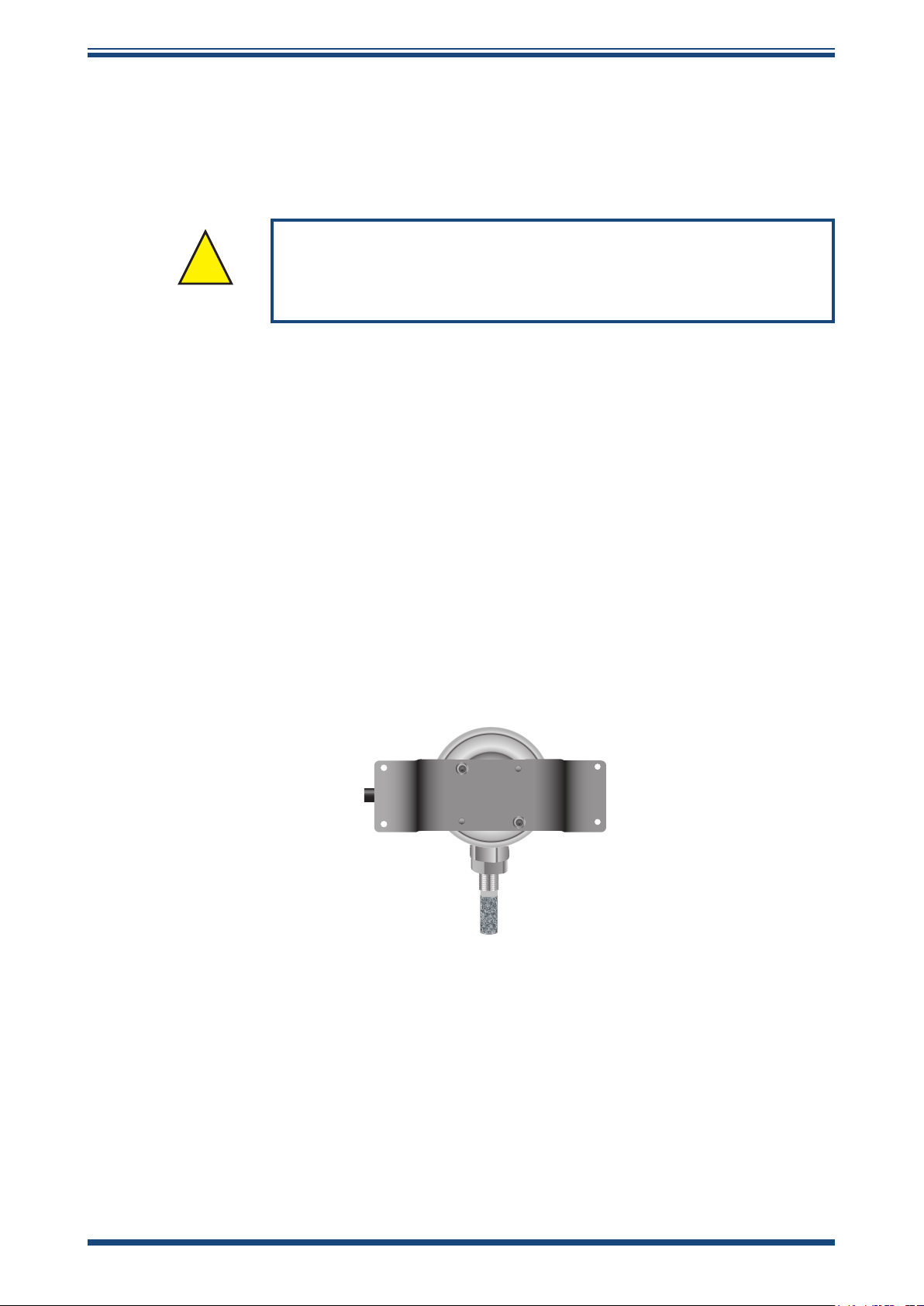
2.2.1 Wall Mount Bracket
The Easidew PRO I.S. can be supplied with an optional wall-mounting bracket. This
allows the customer to physically support the transmitter, ensuring that the stress on
the mounting ange is kept to a minimum.
The bracket needs to be attached to the Easidew PRO I.S. (see
hex screws provided. It can be tted either horizontally or vertically and can then be
attached to a wall or plate to provide support for the transmitter.
Figure 1)
using the
Figure 1
Wall-Mount Bracket
Michell Instruments 3
Page 12
INSTALLATION
Easidew PRO I.S. User’s Manual
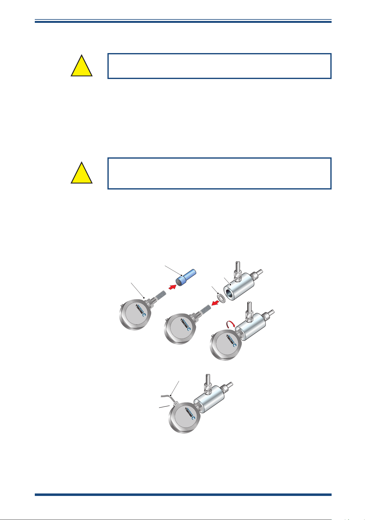
2.2.2 Transmitter Mounting - Sample Block (Optional)
The following procedure must be carried out by a qualied
!
installation engineer.
To mount the transmitter into the sensor block (preferred method), proceed as follows,
refer to
Figure 2.
1. Remove the protective cover (2) (and its desiccant capsule) from the tip of
the transmitter (1).
2. Fit the seal (4) over the threaded part of the transmitter body.
WARNING: Under no circumstances should the sensor guard be
!
handled with the ngers.
3. Screw the transmitter (1) into the sample block (3) and tighten to the
recommended torque setting (see Section 2.2). NOTE: Use the ats of
the hexagonal nut and not the sensor body.
4. Connect a cable (5) to the connector terminal block (see Section 2.3).
2
1
Process Dewpoint Transmitter
Easidew PRO I.S.
Process Dewpoint Transmitter
Easidew PRO I.S.
5
3
4
Process Dewpoint Transmitter
Easidew PRO I.S.
Optional cable
and gland (available
on request)
Figure 2
Transmitter Mounting - Sensor Block
Process Dewpoint Transmitter
Easidew PRO I.S.
4 97130 Issue 16.1, November 2019
Page 13

Easidew PRO I.S. User’s Manual
2.2.3 Transmitter Mounting - Direct Pipeline Connection
INSTALLATION
The transmitter may be directly mounted into a pipe or duct as shown in
Figure 3.
CAUTION: Do not mount the transmitter too close to the
bottom of a bend where any condensate in the pipeline
might collect and saturate the probe.
The pipe or duct will require a thread to match the transmitter body thread. Fixing
dimensions are shown in
Figure 3.
For circular pipework, to ensure the integrity of a
gas tight seal, a mounting ange will be required on the pipework in order to provide a
at surface to seal against.
The following procedure must be carried out by
competent personnel.
1. Ensure that the protective cover (and its desiccant capsule) has been
removed from the tip of the transmitter.
WARNING: Under no circumstances should the
sensor guard be handled with the ngers.
2. Fit a bonded seal (2) over the threaded part of the transmitter body.
3. Screw the transmitter into the pipe (1). Tighten enough to obtain a gas
tight seal. (Torque will depend upon the pipeline material.) NOTE: Do
not overtighten or the thread on the pipework may be stripped.
1
1
2
Process Dewpoint Transmitter
Easidew PRO I.S.
2
Process Dewpoint Transmitter
Easidew PRO I.S.
48mm
Figure 3
Transmitter Mounting - Pipe or Duct
Michell Instruments 5
Page 14

INSTALLATION
2.2.4 Transmitter Mounting - With Additional Process Connection Adapter
The following procedure must be carried out by a qualied
!
Easidew PRO I.S. User’s Manual
installation engineer.
To mount the adapter into the transmitter, proceed as follows (see
1. Ensure that the protective cover (2), and its desiccant capsule (2a), have
been removed from the tip of the transmitter.
2. Fit the bonded seal (3) over the threaded part of the transmitter body.
3. Screw the adapter (4) onto the threaded part of the transmitter and tighten
to 30.5 Nm (22.5 ft-lbs). NOTE: Use the ats of the hexagonal nut and
not the sensor body.
WARNING: Under no circumstances should the sensor guard be
!
4. Screw the transmitter (1) with its seal (3) and adapter (4) into the sample
block (see Section 2.2.2) or pipeline (see Section 2.2.3) and fully tighten
using a wrench until the seal is fully compressed and to the following torque
settings:
G 1/2” BSP 56 Nm (41.3 ft-lbs)
handled with the ngers.
Figure 4)
:
3/4” - 16 UNF ` 40 Nm (29.5 ft-lbs)
1/2” NPT Use a suitable sealant e.g. PTFE tape using
correct taping procedures
NOTE: Use the ats of the hexagonal nut and not the sensor body.
2
2a
4
1
Process Dewpoint Transmitter
Easidew PRO I.S.
Process Dewpoint Transmitter
Easidew PRO I.S.
3
Figure 4
Transmitter Mounting with Adapter
6 97130 Issue 16.1, November 2019
Page 15

Easidew PRO I.S. User’s Manual
1 2 3 4
2.3 Preparation of the Sensor Cable
The sensor cable is NOT supplied as standard.
The crimps supplied must be tted onto any cable installed
into the connector in order to comply with Hazardous Area
Certication of the product.
When making a cable assembly it is important that the cable is correctly terminated
(see below).
INSTALLATION
NOTE:
be applied such that there is no possibility of a conductor strand of a core
becoming free.
When the crimp is made it should have a minimum of 2 positions of crimping. After the
crimp is made it should be trimmed to a length of 5mm.
Cable connection to the Easidew PRO I.S. is made via the connector terminal block.
When the crimps are installed into the connector terminal block ensure they are fully
inserted, before tightening the terminal clamping screws.
Figure 5
shown below, should be followed in detail. The crimps should
mm
Figure 5
10
Wire and Crimp Details
NOTE: Ensure the assembled green wire in terminal 3 remains connected.
Figure 6
When all wire connections are made, ensure that there is a minimum clearance distance
and a minimum creepage distance in air of 2mm (0.8”) between each terminal.
Terminal Block Connection
Michell Instruments 7
Page 16

INSTALLATION
2.4 Electrical Schematic
NOTE: The screen/shield should be connected for maximum performance and
to avoid interference.
Always connect the 4-20 mA return signal to a suitable load
(see
connection, the transmitter may be damaged if allowed to
Figure 7)
operate for prolonged periods.
Easidew PRO I.S. User’s Manual
before the power is applied. Without this
SAFE AREAHAZARDOUS AREA
1 2 3 4
1. Connect cable screen to cable gland.
2. Refer to system drawing in Appendix B.
2.4.1 Electrical Boundaries
600
500
+
-
Figure 7
KFD2-STC4-Ex1 H
KFD0-CS-Ex2.50p
KFD2-CR-Ex1.20200
KFD2-CR-Ex1.30200
KFD0-CS-Ex1.50P
MTL5041
MTL5040
MTL5541
+ 4/20mA
Hazardous Area Connection
LOAD
+VS (20 to 35 V DC)
VS -
400
300
Resistance (ohms)
200
100
12 14 16 18 20 22 24 26 28
Supply Voltage
Figure 8
Maximum Load of Easidew PRO I.S. - Including Cable Resistance
8 97130 Issue 16.1, November 2019
Page 17

Easidew PRO I.S. User’s Manual
3 OPERATION
3.1 Measurement and Conguration
The Easidew PRO I.S. can be congured to provide an output of 4-20 mA (2-wire
connection) for the following:
Dew point -110 to +20°C (-166 to +68°F)
Moisture content in gas 0 - 3000 ppm
Moisture content in liquids 0 - 3000 ppm
The Easidew PRO I.S. can be purchased factory congured as required. Alternatively, the
Easidew PRO I.S. can be congured by the customer, using the Easidew Communications
Kit (EPR-CK) and Easidew Application Software. The Easidew Communications Kit can
be purchased from Michell Instruments or a local representative. For a free copy of the
Application Software contact Michell Instruments’ UK oce (see www.michell.com for
details of Michell’s contact information).
OPERATION
V
W
For moisture content in gas, the calculation from the measured dew point is assumed to
be at atmospheric pressure. Alternatively, a xed gas pressure needs to be programmed
into the Easidew PRO I.S.
For moisture content measurement in liquid, the Easidew PRO I.S. requires the saturation
constant of the liquid to be programmed into the transmitters, either at the factory or
by the customer using the Application Software.
The transmitter requires a 6-point look-up table for saturation constants up to 3000
ppmW over the temperature range 0 to +50°C (+32 to +122°F). Saturation constants
for 8 common liquids can be programmed into the Easidew PRO I.S. via the Application
Software. Alternatively, the user can program saturation constants manually. The
Application Software Help le provides detailed instructions on how to perform this task.
3.2 Sampling Hints
Operation is very simple, assuming the following installation techniques are adhered to:
Be Sure the Sample is Representative of the Gas Under Test:
The sample point should be as close to the critical measurement point as possible. Also,
never sample from the bottom of a pipe as entrained liquids may be drawn into the
sensing element.
Michell Instruments 9
Page 18

OPERATION
Minimize Dead Space in Sample Lines:
Dead space causes moisture entrapment points, increased system response times and
measurement errors, as a result of the trapped moisture being released into the passing
sample gas and causing an increase in partial vapor pressure.
Easidew PRO I.S. User’s Manual
Deadspace
Figure 9
Remove Any Particulate Matter or Oil from the Gas Sample:
Particulate matter at high velocity can damage the sensing element and similarly, at
low velocity, they may ‘blind’ the sensing element and reduce its response speed. If
particulate, such as degraded desiccant, pipe scale or rust is present in the sample gas,
use an in-line lter, as a minimum level of protection. For more demanding applications
Michell Instruments oers a range of sampling systems (for more information contact
www.michell.com).
Use High Quality Sample Tube and Fittings:
Michell Instruments recommends that, wherever possible, stainless steel tubing and
ttings should be used. This is particularly important at low dew points since other
materials have hygroscopic characteristics and adsorb moisture on the tube walls,
slowing down response and, in extreme circumstances, giving false readings. For
temporary applications, or where stainless steel tubing is not practical, use high quality
thick walled PTFE tubing.
Indication of Dead Space
Position Transmitter away from Heat Source:
It is recommended, as good instrumentation practice, that the transmitter is placed
away from any heat source to avoid adsorption/desorption.
10 97130 Issue 16.1, November 2019
Page 19

Easidew PRO I.S. User’s Manual
4 GOOD MEASUREMENT PRACTICE
Ensuring reliable and accurate moisture measurements requires the correct sampling
techniques, and a basic understanding of how water vapor behaves. This section aims
to explain the common mistakes and how to avoid them.
Sampling Materials – Permeation and Diusion
All materials are permeable to water vapor since water molecules are extremely small
compared to the structure of solids, even including the crystalline structure of metals.
The graph above demonstrates this eect by showing the increase in dew point
temperature seen when passing very dry gas through tubing of dierent materials,
where the exterior of the tubing is in the ambient environment.
- 20
- 30
GOOD MEASUREMENT PRACTICE
- 40
- 50
Dew point (ºC)
- 60
- 70
Figure 10
nickel
stainless steel
1 2 3 4 5
Time (hours)
Material Permeability Comparison
nylon
copper
polyethylene
PTFE
What this demonstrates is the dramatic eect that dierent tubing materials have on
the humidity levels of a gas passed through them. Many materials contain moisture
as part of their structure and when these are used as tubing for a dry gas the gas
will absorb some of the moisture. Always avoid using organic materials (e.g. rubber),
materials containing salts and anything which has small pores which can easily trap
moisture (e.g. nylon).
As well as trapping moisture, porous sampling materials will also allow moisture vapor
to ingress into the sample line from outside. This eect is called diusion and occurs
when the partial water vapor pressure exerted on the outside of a sample tube is
higher than on the inside. Remember that water molecules are very small so in this
case the term ‘porous’ applies to materials that would be considered impermeable in
an everyday sense – such as polyethylene or PTFE. Stainless steel and other metals
can be considered as practically impermeable and it is surface nish of pipework that
becomes the dominant factor. Electropolished stainless steel gives the best results over
the shortest time period.
Take into consideration the gas you are measuring, and then choose materials appropriate
to the results you need. The eects of diusion or moisture trapped in materials are
more signicant when measuring very dry gases than when measuring a sample with a
high level of humidity.
Michell Instruments 11
Page 20

GOOD MEASUREMENT PRACTICE
Temperature and Pressure eects
As the temperature or pressure of the environment uctuates, water molecules are
adsorbed and desorbed from the internal surfaces of the sample tubing, causing small
uctuations in the measured dew point.
Easidew PRO I.S. User’s Manual
Adsorption
solid to the surface of a material, creating a lm. The rate of adsorption is increased at
higher pressures and lower temperatures.
Desorption
constant environmental conditions, an adsorbed substance will remain on a surface
almost indenitely. However, as the temperature rises, so does the likelihood of
desorption occurring.
Ensuring the temperature of the sampling components is kept at consistent levels is
important to prevent temperature uctuation (i.e. through diurnal changes) continually
varying the rates of adsorption and desorption. This eect will manifest through a
measured value which increases during the day (as desorption peaks), then decreasing
at night as more moisture is adsorbed into the sampling equipment.
is the adhesion of atoms, ions, or molecules from a gas, liquid, or dissolved
is the release of a substance from or through the surface of a material. In
If temperatures drop below the sample dew point, water may condense in sample
tubing and aect the accuracy of measurements.
Maintaining the temperature of the sample system tubing above the dew point of the
sample is vital to prevent condensation. Any condensation invalidates the sampling
process as it reduces the water vapor content of the gas being measured. Condensed
liquid can also alter the humidity elsewhere by dripping or running to other locations
where it may re-evaporate.
Although ambient pressure does not change drastically in a single location, the gas
sample pressure does need to be kept constant to avoid inconsistencies introduced
by adsorption or desorption. The integrity of all connections is also an important
consideration, especially when sampling low dew points at an elevated pressure. If
a small leak occurs in a high-pressure line, gas will leak out; however, vortices at the
leak point and a negative vapor pressure dierential will also allow water vapor to
contaminate the ow.
Theoretically ow rate has no direct eect on the measured moisture content, but
in practice it can have unanticipated eects on response speed and accuracy. An
inadequate ow rate may:
12 97130 Issue 16.1, November 2019
Page 21

Easidew PRO I.S. User’s Manual
• Accentuate adsorption and desorption eects on the gas passing through
the sampling system.
• Allow pockets of wet gas to remain undisturbed in a complex sampling
system, which will then gradually be released into the sample ow.
• Increase the chance of contamination from back diusion. Ambient air
that is wetter than the sample can ow from the exhaust back into the
system. A longer exhaust tube can help alleviate this problem.
• Slow the response of the sensor to changes in moisture content.
An excessively high ow rate can:
• Introduce back pressure, causing slower response times and unpredictable
changes in dew point
• Result in a reduction in depression capabilities in chilled mirror instruments
by having a cooling eect on the mirror. This is most apparent with gases
that have a high thermal conductivity such as hydrogen and helium.
GOOD MEASUREMENT PRACTICE
System design for fastest response times
The more complicated the sample system, the more areas there are for trapped moisture
to hide. The key pitfalls to look out for here are the length of the sample tubing and
dead volumes.
The sample point should always be as close as possible to the critical measurement
point to obtain a truly representative measurement. The length of the sample line to the
sensor or instrument should be as short as possible. Interconnection points and valves
trap moisture, so using the simplest sampling arrangement possible will reduce the time
it takes for the sample system to dry out when purged with dry gas.
Over a long tubing run, water will inevitably migrate into any line, and the eects of
adsorption and desorption will become more apparent.
Dead volumes (areas which are not in a direct ow path) in sample lines, hold onto
water molecules which are slowly released into the passing gas. This results in increased
purge and response times, and wetter than expected readings. Hygroscopic materials
in lters, valves (e.g. rubber from pressure regulators) or any other parts of the system
can also trap moisture.
Plan your sampling system to ensure that the sample tap point and the measurement
point are as close as possible to avoid long runs of tubing and dead volumes.
Filtration
All trace moisture measurement instruments and sensors are by their nature sensitive
devices. Many processes contain dust, dirt or liquid droplets. Particulate lters are used
for removing dirt, rust, scale and any other solids that may be in a sample stream.
For protection against liquids, a coalescing or membrane lter should be used. The
membrane provides protection from liquid droplets and can even stop ow to the
analyser completely when a large slug of liquid is encountered, saving the sensor from
potentially irreparable damage.
Michell Instruments 13
Page 22

MAINTENANCE
Easidew PRO I.S.
Process Dewpoint Transmitter
5 MAINTENANCE
Calibration
Routine maintenance of the Easidew I.S. is conned to regular re-calibration by
exposure of the transmitter to sample gases of known moisture content to ensure that
the stated accuracy is maintained. Calibration services traceable to the UK
Physical Laboratory
(NIST) are provided by Michell Instruments.
Michell Instruments oers a re-calibration service to suit specic needs. A Michell
representative can provide detailed, custom advice (for Michell Instruments’ contact
information go to www.michell.com).
Sensor Guard Replacement
(NPL) and the US
Easidew PRO I.S. User’s Manual
National
National Institute of Standards and Technology
The sensor is supplied with a stainless steel sintered guard.
The stainless steel guard provides <80μm protection to the dew-point sensor. It is
designed to show any contamination and the guard should be changed if the surface
becomes discolored.
When replacing the guard, care should be taken to handle the guard by the bottom part
only. A replacement guard (SSG) can be obtained by contacting Michell Instruments
(www.michell.com) or your local distributor.
HANDLE,
USING
GLOVES, BY
GREY PART
ON LY
Figure 11
Replacement of Sensor Guard
Bonded Seal
If the installed bonded seal gets damaged or lost, a pack of 5 replacement bonded seals
can be obtained by contacting Michell Instruments, or your local distributor, and quoting
part number 5/8-BS.
14 97130 Issue 16.1, November 2019
Page 23

Easidew PRO I.S. User’s Manual
APPENDIX A
Appendix A
Technical Specications
Michell Instruments 15
Page 24

APPENDIX A
Easidew PRO I.S. User’s Manual
Appendix A Technical Specications
Product Easidew PRO I.S. for Gases Easidew PRO LQ I.S. for Liquids
Performance Specications
Measurement range
Accuracy
Response time
Repeatability
Calibration
–110 to +20°C dew point
–100 to +20°C dew point
±1°C dew point (+20 to –60°C)
±2°C dew point (–60 to –110°C)
5 mins to T95 (dry to wet)
0.5°C dew point
Traceable 13-point calibration and certicate
Electrical Specications
Output signal
Output
Analog output scaled
range
Supply voltage
Load resistance
Current consumption
Saturation constants
(for moisture in liquids
measurements only)
CE conformity
Dew point: –110 to +20°C or –100 to +20°C
Non-standard: mg/m3, lbs/MMSCF natural gas
4–20 mA (2-wire connection, current source); User congurable over range
Dew point or moisture content Moisture content
Moisture content in gas: 0 to 3000 ppm
12–28 V DC
Max 250 Ω @ 12 V (500 Ω @ 24 V)
23 mA max, depending on output signal
V
Approved
Moisture content in liquid: 0 to 1000
Non-standard available upon request
6-point look-up table for saturation constants
up to 1000 ppmW over the temperature
range 0 to +50°C; saturation constants for
10 common liquids can be programmed
into the Easidew PRO LQ I.S. via the
application software; alternatively the user
can program saturation constants manually
Operating Specications
Operating temperature -40 to +60°C
Compensated Temperature
Range
NOTE: The transmitter accuracy statement is only valid for the temperature range: -20/+50°C
-20 to +50°C
Storage Temperature -40 to +60°C
Operating pressure 45 MPa (450 barg) maximum
Flow rate
1 to 5 Nl/min mounted in standard sampling block
0 to 10 m/sec direct insertion
0.1 to 0.3L/min through Easidew
Mechanical Specications
Ingress protection
Intrinsically safe area
certicates *
Canadian pressure vessel
cert
Oxygen service Optional: cleaned for enriched oxygen
Housing material 316 stainless steel
Filter (sensor protection)
Process connection and
material
Weight 1.27kg
Electrical connections Screw terminal via female M20 x 1.5mm gland
Diagnostic conditions
(factory programmed)
Approved galvanic isolators
*
The end user has a responsibility to ensure that when installed in the Hazardous Area, the system is compliant with relevant local
and international installation Standards for the use of equipment in explosive atmospheres.
IP66 in accordance with standard BS EN 60529:1992; NEMA 4 protection in accordance with
standard NEMA 250-2003
See Appendix C
C.R.N. — 11 Canadian provinces
Standard: Stainless steel sintered guard (for protection against ne particulate >80µm)
Optional: HDPE guard (for protection against ne particulate >10µm)
316 stainless steel 5/8” — 18 UNF with bonded seal, G1/2” and 3/4” UNF adaptors available
(material certicate to BS EN 10204 3.1 — see ‘
Condition
Sensor fault
Under-range dew point
Over-range dew point
KFD2-CREX1.20200
KFD2-CREX1.30200
KFD0-CS-EX2.50P MTL5040 KFD0-CS-EX1.50P
KFD2STC4-EX1.H
accessories and spare parts
Output
23 mA
4 mA
20 mA
MTL5541 MTL5041
0 to 1000 ppm
ppm
W
W
sample block
0.1 to 1m/s direct insertion
’ on product order codes)
16 97130 Issue 16.1, November 2019
Page 25

Easidew PRO I.S. User’s Manual
A.1 Dimensions
Transmitter for Cable Gland Installation
APPENDIX A
Transmitter with Wall Mount Bracket
Michell Instruments 17
Page 26

APPENDIX A
Easidew PRO I.S. User’s Manual
Optional Sample Block
Bonded Seal
Figure 12
Dimensions
18 97130 Issue 16.1, November 2019
Page 27

Easidew PRO I.S. User’s Manual
APPENDIX B
Appendix B
System Drawings
Michell Instruments 19
Page 28

APPENDIX B
10/03/06
MSB
Ex90352
SHEET 1 OF 1
NTS
SCALE
SIGN
A3
DATE
MOD. No.ISSUE
DRAWING NUMBE R
TOLERANCES:
UNLESS OTHERWISE STATED
FINISH
DIMENSIONS:
MATERIAL
TITLE
USED ON
APPROVEDCHECKED
DATEDATE
DRAWN
DATE
MICHELL INSTRUMENT S LTD. 01/11/05 DOF03
mm
DRAWING
UNITS
THIS DOCUMENT IS THE PR OPERTY OF MICHELL INSTRUMENTS LTD.
AND MUST NOT BE COPIED NOR D ISCLOSED TO A THIRD PARTY
WITHOUT T HE CONSENT OF MICHELL I NSTRUMENTS.
EASIDEW I.S. and EASIDEW PRO I.S.
DEWPOINT TRANSMITTER SYSTEM
DRAWING
3rd ANGLE
PROJECTION
MICHELL INS TRUMENTS LTD. CAMBRIDGE ©
ANGLES: ±0.5°
HOLE Ø:
+0.1
-0.0
0 DEC. PLACE: ± 0.
5
1 DEC. PLACE : ± 0.2
2 DEC. PLACE : ± 0.1
01 CERT ISS 26/01/07 MSB
02 08057 27/05/08 IMA
4 Inches
100mm
03
PRO
Variation
16/02/09
IMA
04
11165
10/08/11
IMA
05
13395
16/12/13
IMA
INTERFACE BARRIER
REFER TO TABLE ABOVE.
HAZARDOUS AREA
SAFE AREA
(RETURN)
(+)
+VS (20 TO 35V DC)
VS -
LOAD
4/20mA
+
-
GALVANIC ISOLATION INTERFACE
(+)
(-)
DEWPOINT
TRANSMITTER
CERTIFICATION No's:
Baseefa06ATEX0330X
IECEX BAS 06.0090X
3
1
TRANSMITTER VERSION
TERMINAL NUMBER
EASIDEW
I.S.
EASIDEW
PRO I.S.
2
4
EASIDEW I.S. DEWPOINT TRANSMITTER
SYSTEM CERTIFICATE No's: Baseefa07Y0027
Ex ia IIC T4 (-20C TO + 70C)
SYSTEM LABEL
THE CAPACITANCE AND EITHER THE INDUCTANCE OR THE INDUCTANCE TO RESISTANCE RATIO
(L/R) OF THE CABLE MUST NOT EXCEED THE FOLLOWING VALUES:
IIC
IIB
IIA
4.2mH
12.6mH
33mH
THE ISOLATION OF THE SIGNAL WIRES W ITH THE EASIDEW DISCONNECTED, MUST BE ABLE TO
WITHSTAND A 500V AC INSULATION TEST.
AT INSTALLATION OF SYSTEM PERFORM A RISK ASSESSMENT IN ACCORDANCE WITH
EN60079-25:2004 cl.10 AND INSTALL LIGHTENING PROTECTION AS NECESSARY.
THE SYSTEM MUST BE MARKED WITH A DURABLE LABEL. THE LABEL SHOULD APPEAR ON OR
ADJACENT TO THE PRINCIPAL ITEM OF ELECTRICAL APPARATUS IN THE SYSTEM OR AT THE
INTERFACE BETWEEN THE INTRINSICALLY SAFE AND NON-INTRINSICALLY SAFE CIRCUITS. THIS
MARKING SHALL INCLUDE THE FOLLOWI NG INFORMATION:
Baseefa 07Y0027 AND THE WORD SYST OR SYSTEM.
40 nF
613 nF
2.11 µF
54 µH/
217 µH/
435 µH/
GROUP CAPACITANCE INDUCTANCE OR L/R RATI O
(µF) (mH) (µH/ohm)
SEE NOTE 1
*
NOTE 1
. 46nF MAXIMUM CABLE CAPACITANCE IS ACCEPTABLE IN
IIC
INSTALLATIONS
FOR THE INTRINSIC SAFETY ISOLATORS SHOWN IN THE LIST BELOW.
FOR ISO LATORS N
OT LISTED BELOW, BUT APPEARING IN TABLE A, ONLY 40nf
MAXIMUM CABLE CAPACITANCE IS ACCEPTABLE.
KFD0-CS-Ex1.50P
KFD0-CS-Ex2.50P
KFD0-CR-Ex1.20200
KFD0-CR-Ex1.30200
MTL5041
MTL5040
M
T
L
5
4
Ω
Ω
Ω
Type
Isolated Repeater
Dual Isolated
Repeater
Transmitter Supply
Isolator
Transmitter Supply
Isolator
Smart Transm itter
Power Supply
Repeater Power
Supply
Dual Loop Isolator
Repeater Power
Supply
Certif icate Number
BAS98ATEX7343
BAS98ATEX7343
BAS00ATEX7164
BAS00ATEX7164
BAS99ATEX7060
BAS01ATEX7155
BAS98ATEX2227
BaseefaATEX0213
Interface
KFD0-CS-Ex1.50P
KFD0-CS-Ex2.50P
KFD2-CR-Ex1.20200
KFD2-CR-Ex1.30200
KFD2-STC4-Ex1.H
MTL5041
MTL5040
MTL5541
Connection to Easidew I.S.
Pin 1 (+)
Pin 2 (-)
Channel 1 - Pin 1 (+)
Channel 1 - Pin 2 (-)
Channel 2 - Pin 4 (+)
Channel 2 - Pin 5 (-)
Pin 1 (+)
Pin 3 (-)
Pin 1 (+)
Pin 3 (-)
Pin 1 (+)
Pin 3 (-)
Pin 2 (+)
Pin 1 (-)
Pin 2 (+)
Pin 1 (-)
Pin 5 (+)
Pin 4 (-)
Pin 2 (+)
Pin 1 (-)
TABLE A
Appendix B System Drawings
B.1 Baseefa Approved System Drawing
Easidew PRO I.S. User’s Manual
20 97130 Issue 16.1, November 2019
Page 29

Easidew PRO I.S. User’s Manual
B.2 FM Approved System Drawing
APPENDIX B
Michell Instruments 21
Page 30

APPENDIX B
10/03/06
A3
DATEDATE
DATE
MICHELL INSTRUMENTS LTD. 01/11/05 DOF03
4 Inches
Master
Contract: 190597
Report: 2013218
2699225
B.3 CSA Approved System Drawing
Connection to Easidew I.S.
Easidew PRO I.S. User’s Manual
SIGN
DATE
Pin 3 (-)
Pin 3 (-)
Pin 2 (-)
Pin 1 (+)
Channel 1 - Pin 1 (+)
Pin 1 (+)
Channel 1 - Pin 2 (-)
Channel 2 - Pin 5 (-)
Channel 2 - Pin 4 (+)
Pin 3 (-)
Pin 1 (+)
Pin 1 (+)
MOD. No.ISSUE
03 CERT ISS 16/06/08 IMA
06 11081 06/04/11 IMA
07 13395 16/12/13 IMA
04 CERT ISS 25/03/09 IMA
05 CERT ISS 15/06/09 IMA
DRAWING NUMBER
Ex90385CSA
SHEET 1 OF 1
CABLE
+ L
i
L
>
a
, L
CABLE
+ C
i
C
>
a
, C
MAX
I
<
SC
, I
max
V
<
CG
INTRINSIC SAFETY.
Ci = 37nF
Transmitter entity parameters are as follows:
Intrinsically safe(entity), Class 1, Div1, Group A,B,C,D
Hazardous Location Installations
1) Control room equipment may not use or generate ov er 250Vrms.
2) Wire all circuits for power supply per CEC Part 1.
3) Use only entity approved safety barrier or other associated
equipment that satisfy the following conditions:
V
54 H/
217 H/
435 H/
I max < 93mA
V max < 2.8Vdc
5) Ex ia is defined as Intrinsically Safe.
Li = 0uH
4) WARNING: SUBSTITUTION OF COMPONENTS MAY IMPARE
Interface
Certificate Number
Type
-CS-Ex2.50P
KFD0-CS-Ex1.50P
KFD0
BAS98ATEX7343
UL Canada E106378CUL
Dual Isolated
Isolated Repeater
EASIDEW I.S.
TRANSMITTER VERSION
TERMINAL NUMBER
HAZARDOUS LOCATION
CLASS 1, DIVISION 1,
Gps A,B,C, & D
KFD2-CR-Ex1.20200
UL Canada
E106378CUL
BAS98ATEX7343
BAS00ATEX7164
UL Canada E106378CUL
Repeater
DEWPOINT
EASIDEW
EASIDEW
Isolator
Transmitter Supply
Vmax = 28V
Imax = 93mA
Pmax = 820mW
TRANSMITTER
3
1
I.S.
4
2
PRO I.S.
(+)
KFD2-STC4-Ex1.H
KFD2-CR-Ex1.30200
BAS00ATEX7164
BAS99ATEX7060
UL Canada E106378CUL
UL Canada E106378CUL
Isolator
Power Supply
Smart Transmitter
Transmitter Supply
Ci = 37nf
Li = 0
(RETURN)
SCALE
UNITS
DRAWING
+0.1
UNLESS OTHERWISE STATED
TOLERANCES:
3rd ANGLE
PROJECTION
NTS
mm
-0.0
ANGLES: ±0.5°
HOLE Ø:
5
2 DEC. PLACE: ± 0.1
1 DEC. PLACE: ± 0.2
0 DEC. PLACE: ± 0.
DIMENSIONS:
FINISH
EASIDEW I.S. & EASIDEW PRO I.S.
MATERIAL
TITLE
WITHOUT THE CONSENT OF MICHELL INSTRUMENTS.
AND MUST NOT BE COPIED NOR DISCLOSED TO A THIRD PARTY
THIS DOCUMENT IS THE PROPERTY OF MICHELL INSTRUMENTS LTD.
MICHELL INSTRUMENTS LTD. CAMBRIDGE ©
SYSTEM DRAWIN. CSA
DEWPOINT TRANSMITTER
USED ON
APPROVEDCHECKED
MSB
DRAWN
33mH
4.2mH
12.6 mH
(-)
(+)
100mm
OF THE HAZARDOUS AREA CABLES MUST NOT
CSA Certified
Barrier
-
46 nF
613 nF
2.11 F
+
NON-HAZARDOUS LOCATION
4/20mA
VS -
ABCD
(L/R) OF THE CABLE MUST NOT EXCEED THE FOLLOWING VALUES:
THE CAPACITANCE AND EITHER THE INDUCTANCE OR THE INDUCTANCE TO RESISTANCE RATIO
( F) (mH) ( H/ohm)
GROUP CAPACITANCE INDUCTANCE OR L/R RATIO
[CLASSIFIED] LOCATIONS) AND THE NATIONAL ELECTRICAL CODE ANSI/NFPA 70.
USE. i.e. ANSI/ISA RP12.6 (INSTALLATION OF INTRINSICALLY SAFE SYSTEMS FOR HAZARDOUS
WITHSTAND A 500V AC INSULATION TEST .
THE INSTALLATION MUST COMPLY WITH THE INST ALLATION PRACTICES OF THE COUNTRY OF
THE ISOLATION OF THE SIGNAL WI RES WITH THE EASIDEW DISCONNECTED, MUST BE ABLE TO
THE CAPACITANCE AND THE INDUCTANCE
EXCEED THE VALUES GIVEN IN TABLE 1
LOAD
S (20 TO 35V DC)
22 97130 Issue 16.1, November 2019
Page 31

Easidew PRO I.S. User’s Manual
APPENDIX C
Appendix C
Hazardous Area Certication
Michell Instruments 23
Page 32

APPENDIX C
Easidew PRO I.S. User’s Manual
Appendix C Hazardous Area Certication
The Easidew PRO I.S is certied compliant to the ATEX Directive (2014/34/EU), and
IECEx for use within Zone 0, 1 and 2 hazardous areas and has been assessed so by SGS
FIMKO Oy, FINLAND (Notied Body 0598).
The Easidew PRO I.S is certied compliant to the North American Standards (USA and
Canada) for use within Class I, Division 1, Groups A, B, C & D hazardous locations and
has been assessed so by CSA and FM.
C.1 Product Standards
This product conforms to the Standards:
EN60079-0:2012/A11:2013 IEC60079-0:2011
EN60079-11:2012 IEC60079-11:2011
FM Class 3600:1998 CAN/CSA-C22.2 No. 0-10
FM Class 3610:2007 CAN/CSA-C22.2 No. 157-92
FM Class 3810:2005 C22.2 No 142-M1987
C.2 Product Certication
This product is attributed with the product certication codes:
ATEX & IECEx
II 1G Ex ia IIC T4 Ga (-20°C to +70°C)
North American
IS, Class I, Division 1, Groups A, B, C & D, T4
C.3 Global Certicates/Approvals
ATEX Baseefa 06ATEX0330X
ATEX System Baseefa 07Y0027
IECEx IECEx BAS 06.0090X
CSA 2013218
FM 3030238
These certicates can be viewed or downloaded from our website at:
http://www.michell.com
C.4 Terminal Parameters
Ui
li
Pi
Ci
Li
= 28 V
= 93 mA
= 820 mW
= 37 nF
= 0
24 97130 Issue 16.1, November 2019
Page 33

Easidew PRO I.S. User’s Manual
C.5 Special Conditions
1. The wiring connections to the free socket must be made via crimped
connectors in such a way that all the strands of the wire used are held
securely by the crimp.
2. The plastic plug and socket create a potential for electrostatic discharge
so must not be rubbed with a dry cloth or cleaned with solvents.
3. The Easidew PRO I.S Dew-Point Transmitter does not withstand the 500
V AC insulation test to frame. This must be taken into account when
installing the equipment.
C.6 Maintenance and Installation
The Easidew PRO I.S. must only be installed by suitably qualied personnel and in
accordance with the instructions provided and the terms of the applicable product
certicates.
APPENDIX C
Maintenance and servicing of the product must only be carried out by suitably trained
personnel or returned to an approved Michell Instruments’ Service Center.
Michell Instruments 25
Page 34

APPENDIX D
Easidew PRO I.S. User’s Manual
Appendix D
Quality, Recycling
& Warranty
Information
26 97130 Issue 16.1, November 2019
Page 35

Easidew PRO I.S. User’s Manual
Appendix D Quality, Recycling & Warranty Information
Michell Instruments is dedicated to complying to all relevant legislation and directives.
Full information can be found on our website at:
www.michell.com/compliance
This page contains information on the following directives:
• ATEX Directive
• Calibration Facilities
• Conict Minerals
• FCC Statement
• Manufacturing Quality
• Modern Slavery Statement
• Pressure Equipment Directive
APPENDIX D
• REACH
• RoHS3
• WEEE2
• Recycling Policy
• Warranty and Returns
This information is also available in PDF format.
Michell Instruments 27
Page 36

APPENDIX E
Easidew PRO I.S. User’s Manual
Appendix E
Return Document &
Decontamination Declaration
28 97130 Issue 16.1, November 2019
Page 37

Easidew PRO I.S. User’s Manual
Appendix E Return Document & Decontamination Declaration
Decontamination Certicate
IMPORTANT NOTE: Please complete this form prior to this instrument, or any components, leaving your
site and being returned to us, or, where applicable, prior to any work being carried out by a Michell
engineer at your site.
Instrument Serial Number
Warranty Repair? YES NO Original PO #
Company Name Contact Name
Address
Telephone # E-mail address
Reason for Return /Description of Fault:
APPENDIX E
Has this equipment been exposed (internally or externally) to any of the following?
Please circle (YES/NO) as applicable and provide details below
Biohazards YES NO
Biological agents YES NO
Hazardous chemicals YES NO
Radioactive substances YES NO
Other hazards YES NO
Please provide details of any hazardous materials used with this equipment as indicated above (use continuation sheet
if necessary)
Your method of cleaning/decontamination
Has the equipment been cleaned and decontaminated? YES NOT NECESSARY
Michell Instruments will not accept instruments that have been exposed to toxins, radio-activity or bio-hazardous
materials. For most applications involving solvents, acidic, basic, ammable or toxic gases a simple purge with dry
gas (dew point <-30°C) over 24 hours should be sufcient to decontaminate the unit prior to return.
Work will not be carried out on any unit that does not have a completed decontamination declaration.
Decontamination Declaration
I declare that the information above is true and complete to the best of my knowledge, and it is safe for Michell
personnel to service or repair the returned instrument.
Name (Print) Position
Signature Date
F0121, Issue 2, December 2011
Michell Instruments 29
Page 38

NOTES:
Easidew PRO I.S. User’s Manual
30 97130 Issue 16.1, November 2019
Page 39

Easidew PRO I.S. User’s Manual
Michell Instruments 31
Page 40

http://www.michell.com
 Loading...