

Page 1

Easidew Online
Dew-Point Hygrometer
User’s Manual
Easidew Online
°Cdp
°Fdp
Hygrometer
97094 Issue 18.5
March 2016
Page 2

Please fi ll out the form(s) below for each instrument that has been purchased.
Use this information when contacting Michell Instruments for service purposes.
Instrument
Code
Serial Number
Invoice Date
Location of Instrument
Tag No
Instrument
Code
Serial Number
Invoice Date
Location of Instrument
Tag No
Instrument
Code
Serial Number
Invoice Date
Location of Instrument
Tag No
Page 3
°Cdp
°Fdp
Easidew Online
For Michell Instruments' contact information please go to
www.michell.com
© 2016 Michell Instruments
This document is the property of Michell Instruments Ltd. and may not be copied or
otherwise reproduced, communicated in any way to third parties, nor stored in any Data
Processing System without the express written authorization of Michell Instruments Ltd.
Page 4

Easidew Online User’s Manual
Contents
Safety ...............................................................................................................................vii
Electrical Safety ..........................................................................................................vii
Pressure Safety ........................................................................................................... vii
Toxic Materials ............................................................................................................vii
Repair and Maintenance ..............................................................................................vii
Calibration .................................................................................................................. vii
Safety Conformity .......................................................................................................vii
Abbreviations .................................................................................................................... viii
Warnings .......................................................................................................................... viii
1 INTRODUCTION ................................................................................................1
1.1 Features ............................................................................................................ 2
2 INSTALLATION ..................................................................................................3
2.1 Unpacking the Instrument ................................................................................... 3
2.1.1 Unpacking the Easidew Transmitter ................................................................ 4
2.1.2 Unpacking the Monitor .................................................................................. 4
2.1.3 Accessories Pack ........................................................................................... 5
2.2 Easidew Online Components ............................................................................... 5
2.3 Easidew Transmitter ........................................................................................... 6
2.4 Monitor .............................................................................................................. 7
2.5 Monitor Panel Layout .......................................................................................... 7
2.6 Function Keys ..................................................................................................... 9
2.7 Mounting the Monitor ....................................................................................... 10
2.8 Electrical Connections ....................................................................................... 11
2.8.1 AC Power Supply Input ................................................................................ 12
2.8.2 DC Power Supply Input (Optional) ................................................................ 13
2.8.3 Preliminary System Test ............................................................................... 14
2.9 Mounting the Sample Block and Transmitter ....................................................... 14
2.9.1 Sample Block Gas Connections ..................................................................... 14
2.10 Preparation of the Transmitter cable .................................................................. 16
2.11 Cable Connection ............................................................................................. 17
2.12 Electrical Schematic .......................................................................................... 17
2.12.1 Electrical Boundaries ................................................................................... 18
2.13 Transmitter Mounting ........................................................................................ 18
2.13.1 Transmitter Mounting - Sample Block (Optional) ............................................ 19
2.13.2 Transmitter Mounting - Direct Pipeline Connection ......................................... 20
2.13.3 Transmitter Mounting - With Additional Process Connection Adapter .............. 21
2.13.4 Monitor Connection ..................................................................................... 22
2.14 Signal Output Connections ................................................................................ 23
3 OPERATION ....................................................................................................25
3.1 General Operational Information ....................................................................... 25
3.2 Preparation For Operation ................................................................................. 26
3.2.1 First Time Operation .................................................................................... 26
3.3 System Alarms ................................................................................................. 27
3.3.1 Alarm Switching Logic (Default) ................................................................... 27
3.3.2 Reversal of Alarm Switching Logic ................................................................ 28
3.3.3 Alarm Level Set-Up ..................................................................................... 30
3.3.4 Re-Transmitted Output Current Range Set-Up ............................................... 31
3.4 Operating Temperature / ppmV Range ............................................................... 32
3.4.1 Temperature Range Default ......................................................................... 32
iv 97094 Issue 18.5, March 2016
Page 5

Easidew Online User’s Manual
3.4.2 Span and Unit Settings ............................................................................... 33
3.4.3 Alarm Set-Point Limit Confi guration .............................................................. 34
3.4.4 Scale Units to ppmV Set-Up .......................................................................... 35
3.4.5 Monitor Limits When Unit Scaled to ppm
3.5 Digital Communication Parameters Set-Up .......................................................... 37
3.6 Monitor – Reading the Displayed Value Using Modbus RTU Over RS232 ................ 39
4 GOOD MEASUREMENT PRACTICE .....................................................................40
4.1 General Operational Guidelines ......................................................................... 41
4.2 Maintenance and Calibration ............................................................................ 42
4.2.1 Clean Monitor ............................................................................................ 42
4.3 Fault Conditions ............................................................................................... 43
.................................................... 36
V
Figures
Figure 1 Easidew Online Monitor and Transmitter .......................................................1
Figure 2 Unpacking Method ......................................................................................3
Figure 3 Transmitter Unpacking Method ....................................................................4
Figure 4 Monitor Unpacking Method ..........................................................................4
Figure 5 Accessories Pack ........................................................................................5
Figure 6 Easidew Online Components .......................................................................5
Figure 7 Easidew Transmitter ...................................................................................6
Figure 8 Monitor Panel Layout ..................................................................................7
Figure 9 Mounting the Monitor ...............................................................................10
Figure 10 AC Power Supply Connections ...................................................................12
Figure 11 DC Power Supply Connections ...................................................................13
Figure 12 Sample Block Gas Connections ..................................................................15
Figure 13 Connector Terminal Block Removal ............................................................16
Figure 14 Wiring Connections ...................................................................................16
Figure 15 Connector Installation ...............................................................................17
Figure 16 2-Wire Connection Diagram .......................................................................17
Figure 17 Maximum Load of Easidew - Including Cable Resistance ..............................18
Figure 18 Transmitter Mounting - Sensor Block ..........................................................19
Figure 19 Transmitter Mounting - Pipe or Duct...........................................................20
Figure 20 Transmitter Mounting with Adapter ...........................................................21
Figure 21 Transmitter Connections............................................................................22
Figure 22 Monitor Rear Panel Connections ................................................................23
Figure 23 Typical Display .........................................................................................26
Figure 24 Change Alarm Switching Logic ...................................................................29
Figure 25 Set-up Alarm Levels ..................................................................................30
Figure 26 Confi gure Analog Output ...........................................................................31
Figure 27 Span and Unit Settings .............................................................................33
Figure 28 Set-up Alarm Set-Point Limits ....................................................................34
Figure 29 Set-up Monitor (to read ppmV) ...................................................................36
Figure 30 Set-up Data Communications Parameters ...................................................38
Figure 31 Installation Location .................................................................................41
Figure 32 Indication of Dead Space ..........................................................................41
Figure 33 Dimensions .............................................................................................47
Figure 34 RS232 Connections ...................................................................................49
Michell Instruments v
Page 6

Easidew Online User’s Manual
Tables
Table 1 Monitor Front Panel Controls and Indicators ..................................................8
Table 2 Function Keys ..............................................................................................9
Table 3 Summary of Electrical Connections ............................................................. 24
Appendices
Appendix A Technical Specifi cations .............................................................................. 45
A.1 Dimensions ................................................................................. 47
Appendix B RS232 Data Communications Port Connections (Optional) ............................ 49
Appendix C EC Declaration of Conformity ......................................................................51
Appendix D Quality, Recycling & Warranty Information ...................................................53
D.1 Pressure Equipment Directive (PED) 97/23/EC ...............................53
D.2 Recycling Policy .......................................................................... 53
D.3 WEEE Compliance ........................................................................ 53
D.4 RoHS2 Compliance ......................................................................54
D.5 Warranty ..................................................................................... 54
D.6 REACH Compliance ...................................................................... 55
D.7 Calibration Facilities ..................................................................... 55
D.8 Return Policy ............................................................................... 56
D.9 Manufacturing Quality .................................................................. 56
Appendix E Return Document & Decontamination Declaration ........................................ 58
vi 97094 Issue 18.5, March 2016
Page 7

Easidew Online User’s Manual
Safety
The manufacturer has designed this equipment to be safe when operated using the procedures
detailed in this manual. The user must not use this equipment for any other purpose than that
stated. Do not apply values greater than the maximum value stated.
This manual contains operating and safety instructions, which must be followed to ensure the safe
operation and to maintain the equipment in a safe condition. The safety instructions are either
warnings or cautions issued to protect the user and the equipment from injury or damage. Use
competent personnel using good engineering practice for all procedures in this manual.
Electrical Safety
The instrument is designed to be completely safe when used with options and accessories supplied
by the manufacturer for use with the instrument.
Pressure Safety
DO NOT permit pressures greater than the safe working pressure to be applied to the instrument.
The specifi ed safe working pressure (SWP), for this instrument is 45 MPa (450 barg / 6500 psig).
Toxic Materials
The use of hazardous materials in the construction of this instrument has been minimized. During
normal operation it is not possible for the user to come into contact with any hazardous substance
which might be employed in the construction of the instrument. Care should, however, be exercised
during maintenance and the disposal of certain parts.
Repair and Maintenance
The instrument must be maintained either by the manufacturer or an accredited service agent. For
contact information visit the website at www.michell.com.
Calibration
The recommended calibration interval for this instrument is 12 months unless it is to be used in a
mission-critical application or in a dirty or contaminated environment in which case the calibration
interval should be reduced accordingly. The instrument should be returned to the manufacturer,
Michell Instruments Ltd., or one of their accredited service agents for re-calibration.
Safety Conformity
This product meets the essential protection requirements of the relevant EU and US directives.
Michell Instruments vii
Page 8

Abbreviations
The following abbreviations are used in this manual:
AC alternating current
atm pressure unit (atmosphere)
barg pressure unit (=100 kP or 0.987 atm) gauge
bara bar absolute
°C degrees Celsius
°F degrees Fahrenheit
DC direct current
ft foot (feet)
g gram(s)
Hz Hertz
lbf-ft pound force per foot
Nl/min normal liters per minute
m meter(s)
mA milliampere
max maximum
min minute(s)
mm millimeter(s)
MPa megapascal (Pascals x10
m/sec meters per second
Nm Newton meter
ppm
parts per million (by volume)
V
RS232 serial data transmission standard
Rx receive
scfh standard cubic feet per hour
scfs standard cubic feet per second
SWP safe working pressure
sec second(s)
temp temperature
V Volts
Ω Ohms
Easidew Online User’s Manual
6
)
Warnings
The following general warnings listed below are applicable to this instrument. They are
repeated in the text in the appropriate locations.
Where this hazard warning symbol appears in the following
sections, it is used to indicate areas where potentially
hazardous operations need to be carried out.
Where this symbol appears in the following sections it is used
to indicate areas of potential risk of electric shock.
viii 97094 Issue 18.5, March 2016
Page 9
Easidew Online User’s Manual
1 INTRODUCTION
The Easidew Online dew-point hygrometer is an instrument designed for the continuous
online measurement of moisture content in non-corrosive gases, over an operational
range of -100 to +20ºCdp (-148 to +68ºFdp).
The system comprises a programmable monitor confi gured to accept a 4-20 mA current
loop signal from an impedance-type dew-point temperature measurement transmitter.
The span of the transmitter is set to cover the dew-point range -100 to +20ºCdp (-148
to +68ºFdp) at operating pressures up to 45 Mpa (450 barg / 6500 psig).
The monitor also has a re-transmission facility which buffers the transmitter output for
onward transmission to other systems. The transmitter input to the monitor is confi gured
as a 4-20 mA current loop signal and the re-transmitted output can be confi gured as
either a 4-20 mA or a 0-20 mA current loop signal (ranged as per the input).
Two alarm outputs (high and low) are provided for connection to external systems.
Alarm 1 provides a set of single pole make contacts and Alarm 2 provides a set of
changeover contacts. Both sets are potential free and Alarm 1 contacts (single pole
make) are rated at 250 V, 3 A and the Alarm 2 contacts (changeover) are rated at
250 V, 5 A.
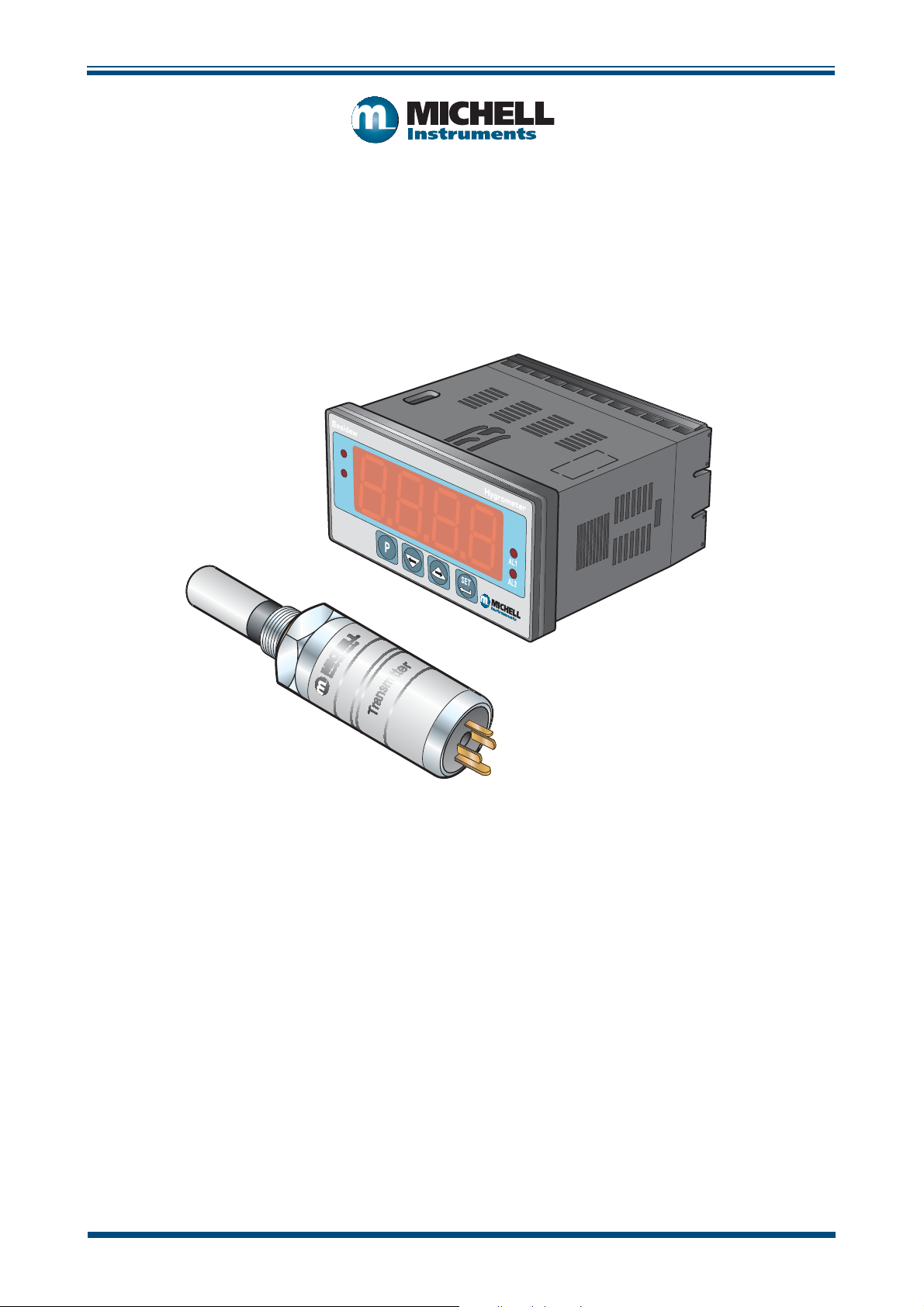
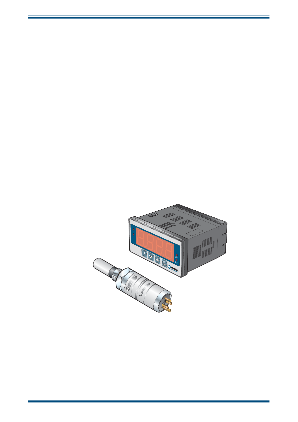
INTRODUCTION
Figure 1
shows the monitor and the transmitter.
Easidew Online
°Cdp
°Fdp
Hygrometer
Figure 1
Easidew Online Monitor and Transmitter
Michell Instruments 1
Page 10

INTRODUCTION
1.1 Features
The Easidew Online Hygrometer is simple to use and install, and can be confi gured to
meet specifi c needs.
• 5/8”- 18 UNF process connections
Easidew Online User’s Manual
• Dew-point or ppm
• IP66 (NEMA 4) Sensor and IP65 (NEMA 12) Monitor (front panel only)
• Measurement range -100 to +20°C (-148 to +68°Fdp)
• Dual alarms
• Accuracy ±2°Cdp
• Clear and easy to read display
• Calibration certifi cate (traceable to NPL and NIST)
moisture content
V
2 97094 Issue 18.5, March 2016
Page 11
Easidew Online User’s Manual
2 INSTALLATION
It is essential that the connection of electrical and gas supplies
to this instrument be undertaken by competent personnel.
2.1 Unpacking the Instrument
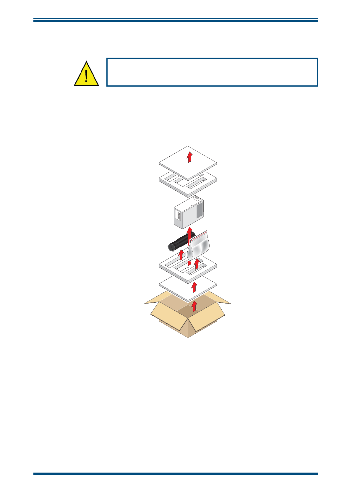
The Easidew instruments and accessories are packed into a box and the method of
unpacking is shown as follows:
INSTALLATION
Figure 2
Open the box and unpack carefully as follows. Save all the packing materials for the
purpose of returning the instrument for re-calibration or any warranty claims. Note that
the packing method may vary slightly in the U.S.
1. Remove the top packing (1)
2. Remove the dew-point transmitter box (3)
3. Remove the accessories pack (4)
4. Remove the monitor box (2)
Unpacking Method
Michell Instruments 3
Page 12
INSTALLATION
2.1.1 Unpacking the Easidew Transmitter
NOTE: For environmental and operating conditions refer to Appendix A.
Easidew Online User’s Manual
Unpack the dew-point transmitter box as follows
Figure 3
Transmitter Unpacking Method
:
7653 421
1. Unscrew the cap (1) from the packing tube (6). Remove the foam block
(2).
1. Remove the transmitter from the tube, complete with the body cover (4)
and tip cover (5).
2. Remove the body cover (4) and the tip cover (5) but leave the blue plastic
protective cover (3) in place until ready for installation.
NOTE: The transmitter sensing element is protected while in transit by a blue
cover containing a small desiccant capsule. The connection pins are protected
by a red plastic cap. None of these plastic items are required for the operation
of the transmitter.
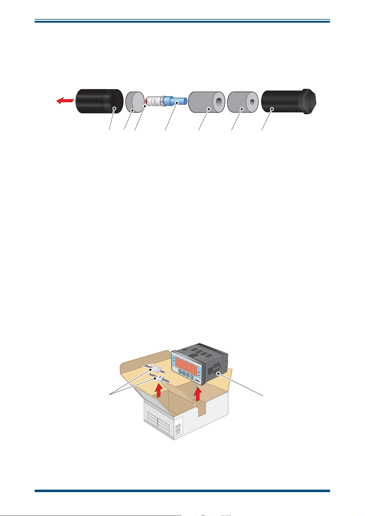
2.1.2 Unpacking the Monitor
The monitor (2) is packed, together with its fi xing clamps (1) as shown below.
1
SMART OUTPUT Module System
Process Indicator
Figure 4
°Cdp
°Fdp
Monitor Unpacking Method
2
4 97094 Issue 18.5, March 2016
Page 13
Easidew Online User’s Manual
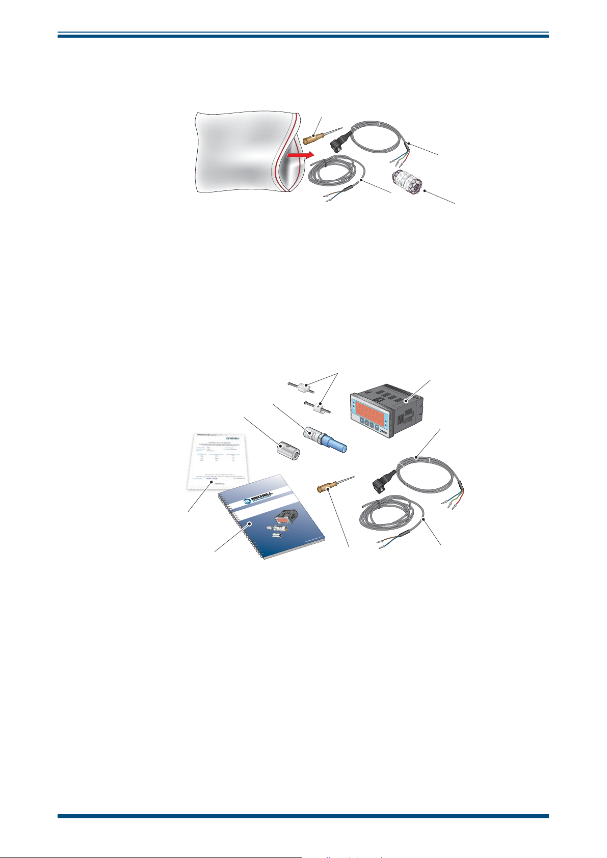
2.1.3 Accessories Pack
The accessories pack is shown below.
INSTALLATION
1
3
2
4
Figure 5
Remove the screwdriver (1), the two leads (2) and (3) and the sample block (4) from
the bag.
2.2 Easidew Online Components
On delivery please check that all the following standard components are present in the
packing box. Report any shortages to Michell Instruments, immediately.
9
8
Easidew Online
Dew-Point Hygrometer
7
User’s Manual
Accessories Pack
1
dp
C
°
Fdp
°
2
3
6
Figure 6
97211 Issue 01, May 2010
5
Easidew Online Components
4
1. Monitor clamps (2 off)
2. Easidew Monitor
3. Transmitter cable assembly
4. Power cable
5. Screwdriver
6. User’s Manual
7. Calibration certifi cate
8. Sample block
9. Easidew transmitter
Michell Instruments 5
Page 14
INSTALLATION
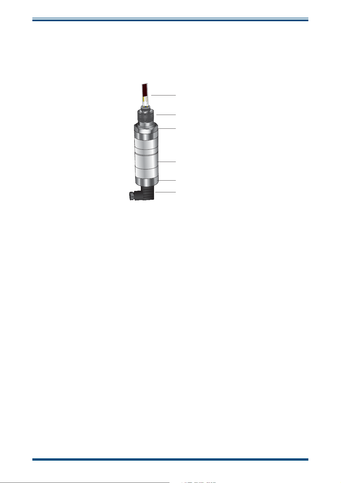
2.3 Easidew Transmitter
NOTE: The transmitter’s sensing element is shown for illustration purposes
only. Please keep the HDPE or SS guard fi tted at all times, if possible.
Easidew Online User’s Manual
h
C
I
M
u
r
t
s
n
I
S
F
7
2
R
0
2
a
+
n
/
g
e
0
:
0
1
-
r
e
t
s
a
c
n
a
L
8
4
m
a
C
,
y
l
E
e
t
i
n
U
Figure 7
Sensing Element
h
E
H
n
e
m
6
0
9
0
B
y
a
W
s
e
g
d
i
r
b
6
B
C
g
n
i
K
d
h
Process Connection
Hexagonal Nut
h
Transmitter Label
h
Transmitter Cover
h
Electrical Connector
Easidew Transmitter
6 97094 Issue 18.5, March 2016
Page 15
Easidew Online User’s Manual
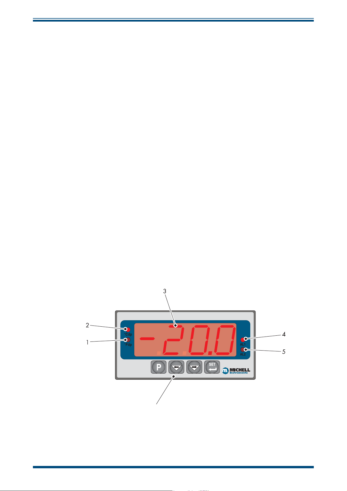
2.4 Monitor
The controls and indicators associated with the Easidew Online are located on the front
panel of the monitor.
Connections to the Easidew dew-point transmitter, the RS232 communications port and
the external power supply are all made to the rear panel of the monitor.
INSTALLATION
Figure 8
shows the layout of these controls and Tables 1 and 2 describe their respective
operational functions.
Dew-point temperature units are displayed by one of the two LED’s located to the left
of the display. On delivery, °Cdp is set-up as standard. If required, the units can be
changed to °F. The method of confi guring the unit for °F is described in Section 3.4.
Optionally, the instrument can be set-up to read dew point in parts per million (ppm
range 0 to 3000 ppm
. This option requires the transmitter to be set-up for ppmV either
V
),
V
at the time of ordering or subsequently via Michell application software. NOTE: No
specifi c ppm
LED indicator is provided on the monitor; ppmV is selected if
V
neither the °Cdp nor the °Fdp temperature indicators are illuminated.
Two temperature alarm indications are provided by two LEDs located on the right hand
side of the display. These are marked
AL1 (low) and AL2 (high). Access to the alarm
relay contacts is provided on the rear panel. The connection for these alarm relay
contacts is shown in Section 2.13.
NOTE: Every display is factory fi tted with 2 alarm relays as standard.
2.5 Monitor Panel Layout
Easidew Online Hygrometer
6
Figure 8
Monitor Panel Layout
Michell Instruments 7
Page 16

INSTALLATION
Item Description
°Fdp
Easidew Online User’s Manual
1
2
3
4
When illuminated, this LED indicates that the displayed dew-point reading is in degrees
Fahrenheit.
Note: If neither the °Fdp or °Cdp LED is lit, ppm
°Cdp
When illuminated, this LED indicates that the displayed dew-point reading is in degrees
Celsius.
Note: if neither the °Cdp nor °Fdp LED is lit, ppm
Main dew-point temperature display
Flashes to alternately indicate ErrL (error low) and temperature reading for low
temperatures under-range (lower than -100°Cdp (-148°Fdp) or -129.9°Cdp (199.9°Fdp)
for an open loop condition).
Flashes to alternately indicate
temperature over-range.
AL1
When illuminated, this LED indicates that the dew-point temperature programmed
for Alarm 1 has exceeded the programmed threshold. Under these conditions the
alarm relay contacts associated with this alarm (normally open) will change state
(close) and will remain closed until the dew-point temperature moves back within
the programmed operational limit.
ErrH (error high) and temperature reading for high
is selected.
V
is selected.
V
Alarm 1 is usually allocated to the Low alarm setting.
These relay contacts are rated at 250 V, 3 A and are connected as shown in Section 2.13.
Section 3.3.3 describes the setting up of AL1 trip points.
AL2
When illuminated this LED indicates that the dew-point temperature programmed for
Alarm 2 has exceeded the programmed threshold. Under these conditions the alarm
relay changeover contacts associated with this alarm will change state and will remain in
this state until the temperature moves back to within the programmed operational limit.
5
Alarm 2 is usually allocated to the High alarm setting.
These changeover relay contacts are rated at 250 V, 5 A and are connected as shown
in Section 2.13.
Section 3.3.3 details the setting up of AL2 trip points.
The four function keys are used for setting up the
6
P
SET
monitor.
Table 2 describes the operation of the keys.
Table 1 Monitor Front Panel Controls and Indicators
8 97094 Issue 18.5, March 2016
Page 17
Easidew Online User’s Manual
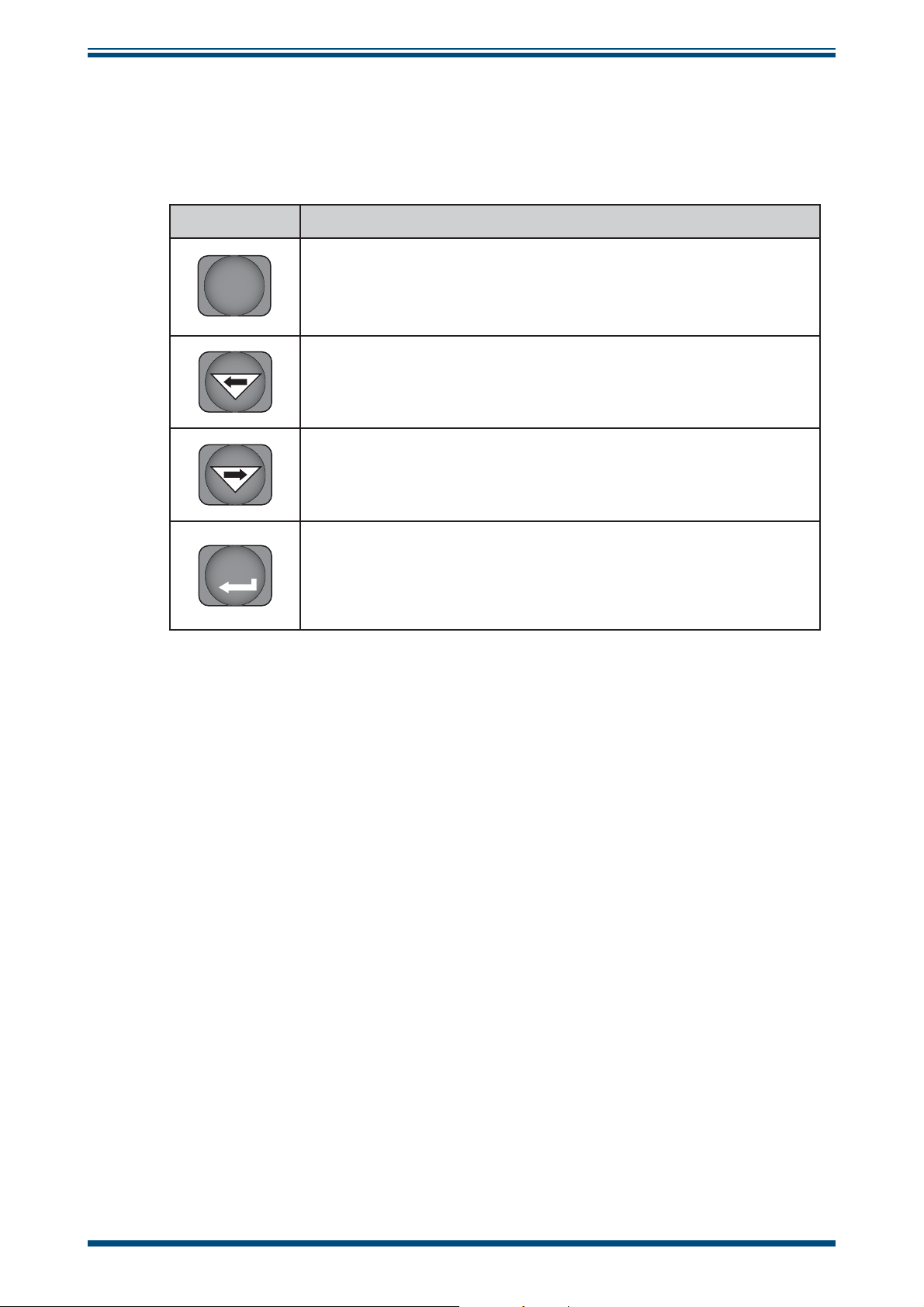
2.6 Function Keys
INSTALLATION
The function key panel is shown in
Table 2 describes the operation of the keys.
Item Description
Figure 8
P (Program) key
P
This key is used to access the programming menus and to select
sub-menus within the list.
Left arrow (decrement) key
This key is used to access sub-menus and, within individual submenus, to decrease the numeric value of the selected parameter.
Right arrow (increment) key
This key is used to access sub-menus and, within individual submenus, to increase the numeric value of the selected parameter.
SET key
SET
Depending upon the context, this key is used to access the set
value of the selected process fi eld and as an Accept key for new
parameter values.
.
Table 2 Function Keys
Michell Instruments 9
Page 18
INSTALLATION
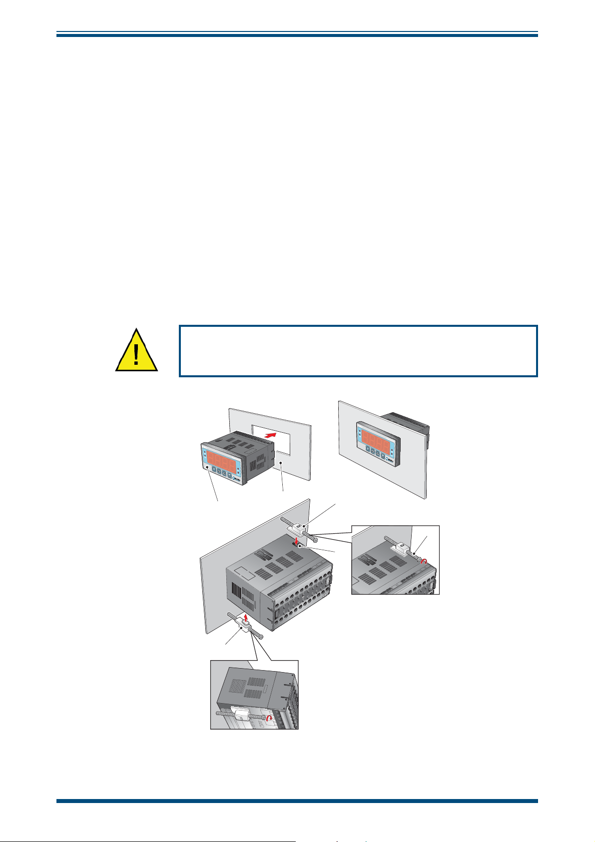
2.7 Mounting the Monitor
The monitor is designed for panel mounting and requires a panel cut-out of 46 x 92mm
(1.8 x 3.6”). The recommended panel thickness is 2 to 5mm (0.08 to 0.2”).
Easidew Online User’s Manual
To mount the unit, proceed as follows (refer to
Figure 9):
1. Pass the monitor (1) through the front of the panel (2).
2. Support the monitor and insert the hook on the topside of the clamp (3)
into the slot (4) located on top of the monitor casing.
3. Tighten the fi xing screw (5) fi nger tight, against the back of the panel.
4. Insert the hook on the second clamp (6) into the slot located on the
underside of the instrument casing and tighten the fi xing screw, fi nger
tight, against the back of the panel.
5. Ensure that the monitor is sitting fl ush to the front of the panel (2) and
tighten the fi xing screws evenly against the back of the panel.
Caution: Do not overtighten the screws as this could cause
the case to crack.
1
6
Figure 9
2
3
4
Mounting the Monitor
5
10 97094 Issue 18.5, March 2016
Page 19

Easidew Online User’s Manual
2.8 Electrical Connections
Electrical connections to the Easidew Online system are as follows:
• AC power supply, 100 to 240 V AC (-15%, +10%), 50/60 Hz, 6 VA. A low
voltage (24 V DC) option is also available.
• Transmitter current loop input, 4-20 mA (24 V DC loop power provided
by monitor).
• Alarm 1 (Low), potential free contacts, single pole make. Contacts rated
at 250 V, 5 A.
• Alarm 2 (High), potential free contacts, single pole changeover. Contacts
rated at 250 V, 5 A.
• Re-transmitted input signal from the dew point transmitter 4-20 mA or
0-20 mA.
INSTALLATION
Michell Instruments 11
Page 20
INSTALLATION
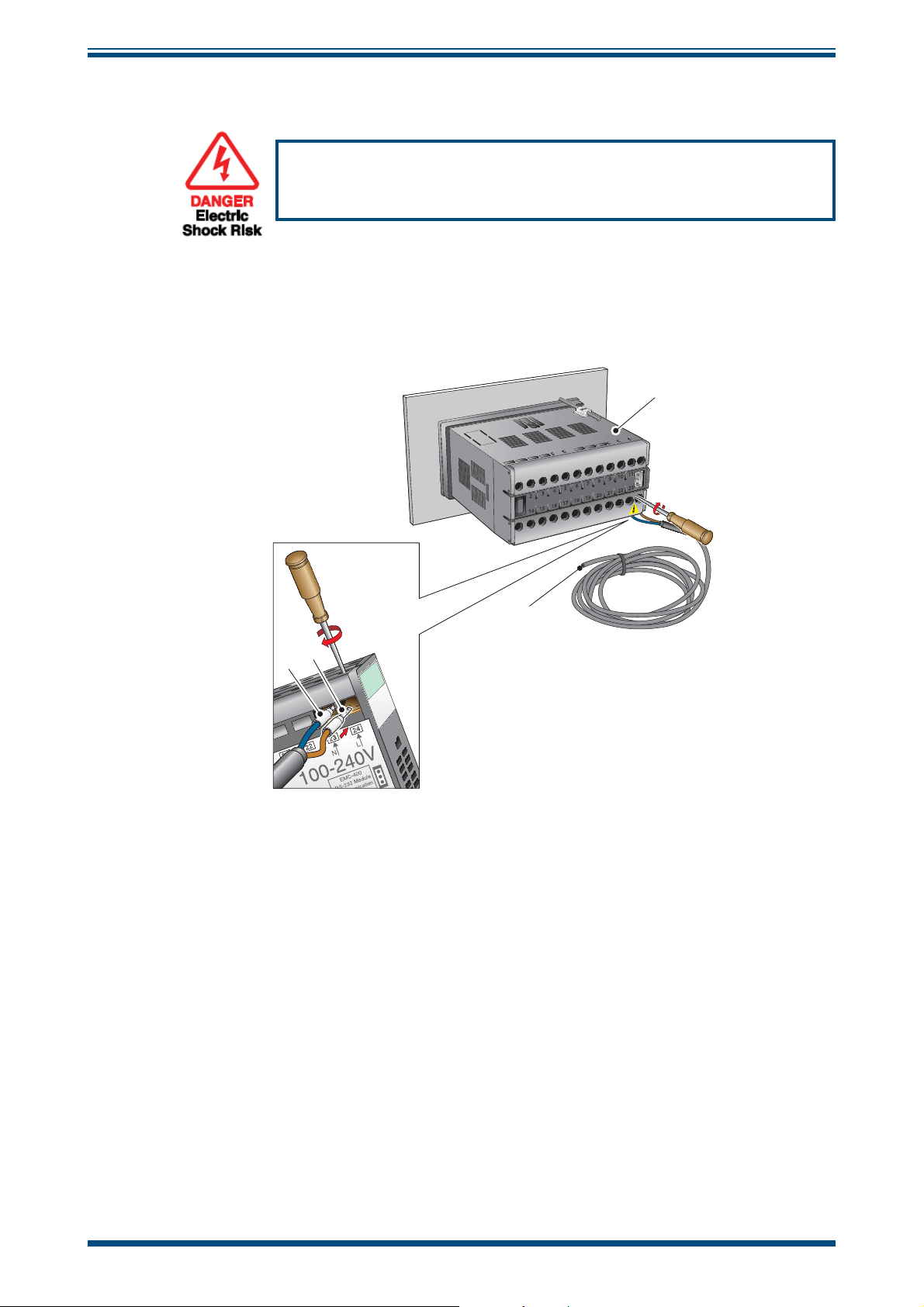
2.8.1 AC Power Supply Input
It is essential that the connection of electrical supplies to this
instrument be undertaken by competent personnel.
Easidew Online User’s Manual
Connect the AC power supply to the monitor as shown in
Figure 10
. Refer also to Table
3 which gives a summary of all the connections to the rear panel of the monitor.
1
11
10
9
8
7
6
5
4
3
2
18
17
16
15
14
4
3
2
23
22
21
20
19
Monitor
viewed from underneath
Figure 10
AC Power Supply Connections
1. Ensure that no power is connected to the mains lead.
2. Connect the blue (white - US standard) (neutral) lead (2) to terminal 23
on the rear panel of the monitor.
3. Connect the brown (black - US standard) (live) lead (3) to terminal 24 on
the rear panel of the monitor.
4. Strip back the insulation on the free end of the power cable and wire to
an appropriate power supply plug (brown lead to live supply terminal,
blue lead to neutral supply terminal).
5. Check that the wiring has been completed correctly before connecting to
a mains power supply.
12 97094 Issue 18.5, March 2016
Page 21
Easidew Online User’s Manual
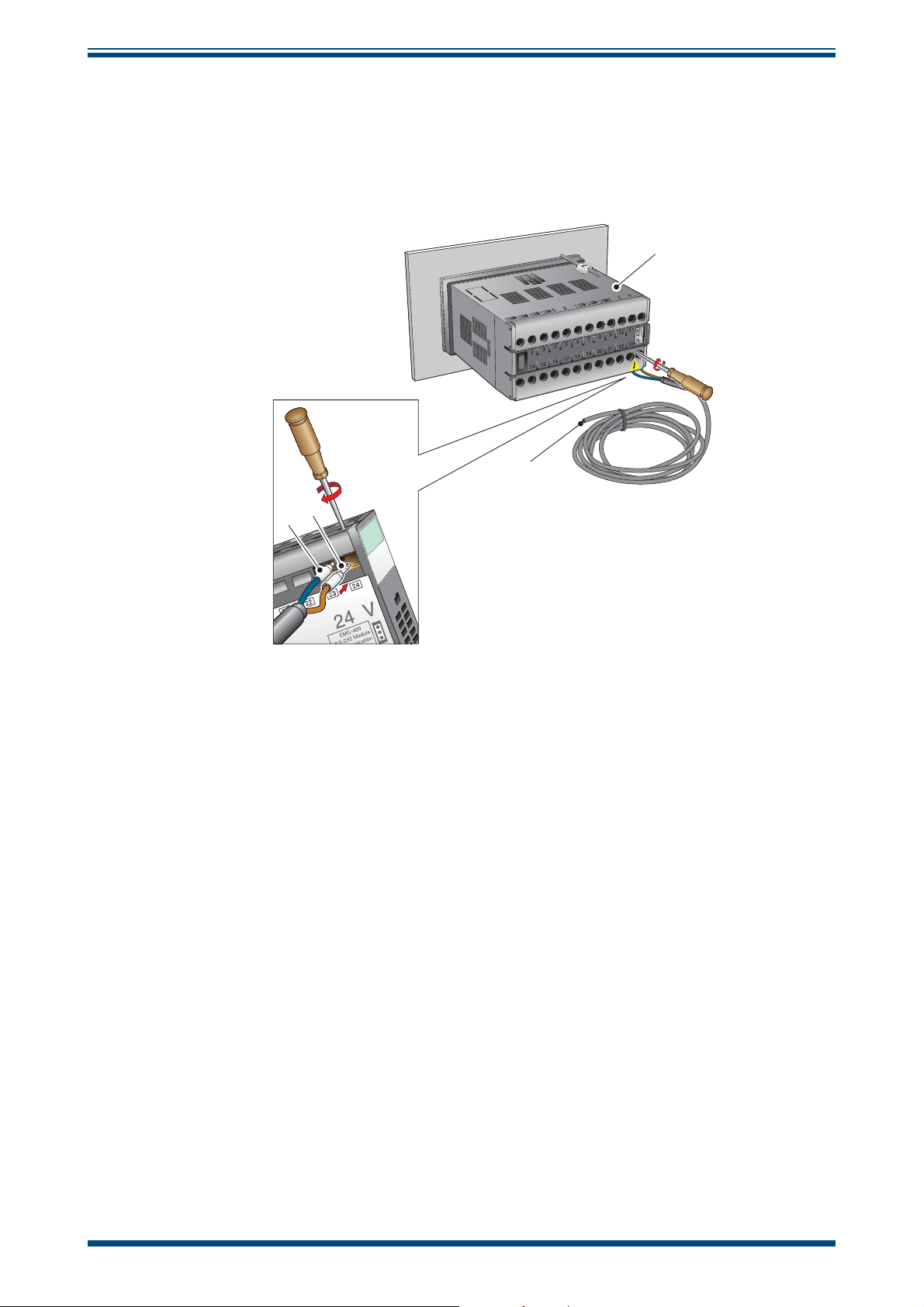
2.8.2 DC Power Supply Input (Optional)
INSTALLATION
Connect the DC power supply to the monitor as shown in
Figure 11
. Refer also to Table
3 which gives a summary of all the connections to the rear panel of the monitor.
1
11
10
9
8
7
6
5
4
3
2
18
17
16
15
14
4
3
2
23
22
21
20
19
+
-
Monitor
viewed from underneath
Figure 11
DC Power Supply Connections
1. Ensure that no power is connected to the mains lead.
2. Connect the blue (white - US standard) lead (2) to terminal 23 on the rear
panel of the monitor.
3. Connect the brown (black - US standard) lead (3) to terminal 24 on the
rear panel of the monitor.
4. Strip back the insulation on the free end of the power cable and wire
to an appropriate power supply plug (brown lead to positive (+) supply
terminal, blue lead to negative (-) supply terminal).
5. Check that the wiring has been completed correctly before connecting to
a 24 V power supply.
Michell Instruments 13
Page 22

INSTALLATION
2.8.3 Preliminary System Test
Before wiring the external signal outputs and the transmitter (current loop open),
perform a system check as follows:
1. Switch off and disconnect the power supply.
Easidew Online User’s Manual
2. Connect to an AC or DC supply and switch the supply
display should come on. Depending on the version of the monitor there
are 2 types of sequential messages appearing on the display.
Type 1: - Digits sequentially tested, each in turn displaying the fi gure
followed by
Type 2: - Digits sequentially tested, each in turn displaying the fi gure
followed by
The ºCdp LED will, by default, also be illuminated and it is possible, that
even though no alarms are currently set-up, one of the alarm LED’s may be
illuminated.
NOTE: If the instrument is confi gured to read ppmV neither of the
temperature LED indicators will be lit.
3. If a loop calibrator is available, set it to Ext loop and connect to terminal
4 (positive) and terminal 3 (negative) of the process indicator.
4. Set the output current of the loop calibrator to 4 mA, the display should
now be reading
rUO2 then oAor and Sbr
ruOO then oror and alternately fl ashing ErrL and -129.9
-100.0.
ON. The monitor
8
8
5. Set the output current of the loop calibrator to 20 mA, the display should
now be reading
6. Switch off and disconnect the loop calibrator.
Before wiring the external signal outputs and the transmitter, perform a system check
as follows:
020.0.
2.9 Mounting the Sample Block and Transmitter
2.9.1 Sample Block Gas Connections
Sample gas connections are made to the Gas In and Gas Out ports on the sample block
see
Figure 12.
for connection purposes the ports are interchangeable).
Normally, connections are made via stainless steel pipework, in which case the sensor
block/transmitter assembly will be self supporting. If Tefl on tubing is used it may be
necessary to support the assembly with a body clip.
Either port on the sample block may be used as the Gas Input port (i.e.
14 97094 Issue 18.5, March 2016
Page 23

Easidew Online User’s Manual
1
2
3
4
5
INSTALLATION
6
5
4
2345
1
3
2
1
Figure 12
Sample Block Gas Connections
Both the Input and Output gas connections are ⅛” NPT. It is recommended that both
the Gas Input and Output connections are made made via ⅛” NPT to 6mm or ⅛” NPT
to ¼” stainless steel tube adaptors (2 to 5 -
Figure 12)
. The method of connection to
the sensor block (6) is as follows:
NOTE: The following description relates to 6mm tube fi xings. The sample
block ports are both ⅛” NPT female process connections. Tube adaptors are
not supplied with the equipment but can be obtained by contacting your local
distributor or Michell Instruments (see www.michell.com for details).
1. Cut a suitable length of 6mm (¼” U.S.) stainless steel tubing (1) to the
correct length and, if necessary, bend to shape to suit the location of the
sensor block assembly. NOTE: To facilitate ease of connection to the
port, at least 75mm (3”) of the tubing coming out of the Gas In
port must be straight.
2. Clean off any burrs or metal shavings adhering to the tubing.
3. Screw the ⅛” NPT (¼” U.S.) NPT Swagelok adaptor (5) into the ⅛” NPT
(¼” U.S.) NPT inlet port in the sensor block (6) and tighten to a torque
setting of 35 Nm (25 lbf-ft).
4. Pass the stainless steel tubing (1) through the locking nut (2). NOTE:
Threads towards the gas port.
5. Fit the back ferrule (3) over the stainless steel tubing (1) with the bevelled
end facing the back of the front ferrule (4).
6. Place the front ferrule (4) over the stainless steel tubing (1), bevelled end
towards the adaptor (5).
7. Push the stainless steel tubing (1) as far as it will go into the adaptor (5)
and tighten up the locking nut (2) fi nger tight.
8. Hold the adaptor (5) fl ats with a spanner and tighten up the locking
nut (2) to a torque setting of 35 Nm (25 lbf-ft) (1¼ turns). This action
compresses the front ferrule (4) and back ferrule (3) onto the tubing to
form a gas tight seal.
9. Connect up the other gas port as described in steps 1 to 8 above.
Michell Instruments 15
Page 24

INSTALLATION
2.10 Preparation of the Transmitter cable
The transmitter cable is supplied as standard. A cable can be obtained by contacting
your local distributor or Michell Instruments (see www.michell.com for details).
Cable connection to the Easidew transmitter is made via the removable connector.
Removing the central screw enables the connector terminal block to be removed from
the outer housing by using a small screwdriver to prise it clear.
i
O-ring
and washer
Easidew Online User’s Manual
Figure 13
Connector Terminal Block Removal
Caution: When removing the central screw ensure that the
small sealing O-ring and the washer are retained on the screw
and are present during re-installation.
For the transmitter to work properly, and to achieve maximum performance, the
transmitter cable must be connected to the sensor connector as shown in the drawing
below:
Note: The drawing below shows the identity of the connector terminals and
wiring connections of the cable manufactured by Michell Instruments:
GN
RD
BL
GREEN - 4-20 mA
RED + POWER
BLUE - SCREEN
BRAID
h
GREEN - 4-20 mA
(SOURCE)
BLUE - SCREEN
RED + POWER
SCALE 2:1
i
SHORT
AS POSSIBLE
+POWER
j
GREEN
SIGNAL (SOURCE)
1
3
RED
2
VIEW ON REAR
OF CONNECTOR
BRAID
h
BLUE
GND
4
Figure 14
SCREEN
h
GREEN
YELLOW
BLUE
RED
Wiring Connections
Always connect the 4-20 mA return signal to a suitable load
(see
Figure 14)
before the power is applied. Without this
connection, the transmitter may be damaged if allowed to
operate for prolonged periods.
16 97094 Issue 18.5, March 2016
Page 25

Easidew Online User’s Manual
2.11 Cable Connection
When installing the connector, and to ensure that full ingress protection is achieved, the
securing screw (with the O-ring and washer) must be tightened to a minimum torque
setting of 3.4 Nm (2.5 ft-lbs). The transmitter cable used must be a minimum diameter
of 4.6mm (0.2”).
2
INSTALLATION
4
1
Figure 15
Connector Installation
4
3
2.12 Electrical Schematic
NOTE: The screen/shield should be connected for maximum performance
and to avoid interference.
3
1
Figure 16
Screen/
Shield
2-Wire Connection Diagram
Max Load
250R @ 12V
500R @ 24V
+
Supply
12V Min
28V Max
Michell Instruments 17
Page 26

INSTALLATION
2.12.1 Electrical Boundaries
600
500
400
300
Resistance (ohms)
200
Easidew Online User’s Manual
100
12 14 16 18 20 22 24 26 28
Figure 17
2.13 Transmitter Mounting
Prior to installation of the transmitter, unscrew and remove the blue plastic cover and
retain for future use. Take care to prevent any contamination of the sensor before
installation (handle the transmitter by the main body only, avoiding contact with the
sensor guard).
The Easidew can be mounted into either a fl ow-through sensor sampling block (optional)
or directly inserted into a pipe or duct and can be operated at pressures of up to 45 MPa
(450 barg / 6500 psig) when fi tted with the bonded seal provided.
Maximum Load of Easidew - Including Cable Resistance
Supply Voltage
The recommended gas fl ow rate, when mounted in the optional sampling block, is 1 to
5 Nl/min (2.1 to 10.6 scfh). However, for direct insertion applications, gas fl ow can be
from static to 10 m/sec (32.8 fps).
NOTE: Pass the bonded seal over the 5/8”- 18 UNF mounting thread and
assemble into the sampling location by hand using the wrench fl ats only. DO
NOT grip and twist the sensor cover when installing the sensor.
When installed, fully tighten using a wrench until the seal is fully compressed and to the
following torque setting:
5/8” - 18 UNF 30.5 Nm (22.5 ft-lbs)
18 97094 Issue 18.5, March 2016
Page 27

Easidew Online User’s Manual
2.13.1 Transmitter Mounting - Sample Block (Optional)
The following procedure must be carried out by a
qualifi ed installation engineer.
To mount the transmitter into the sensor block (preferred method), proceed as follows,
refer to
1. Ensure that the protective cover (2), and its desiccant capsule (2a), have
2. Fit the bonded seal (4) over the threaded part of the transmitter body.
Figure 18.
been removed from the tip of the transmitter.
WARNING: Under no circumstances should the sensor
guard be handled with the fi ngers.
INSTALLATION
3. Screw the transmitter (1) into the sample block (3) and tighten to a
minimum torque setting of 30.5 Nm (22.5 ft-lbs). NOTE: Use the fl ats
of the hexagonal nut and not the sensor body.
4. Fit the transmitter cable/connector assembly to the plug located on the
base of the transmitter and tighten the fi xing screw (see Section 2.3).
2
2a
1
3
4
Figure 18
Transmitter Mounting - Sensor Block
Michell Instruments 19
Page 28

INSTALLATION
Easidew Online User’s Manual
2.13.2 Transmitter Mounting - Direct Pipeline Connection
The transmitter may be directly mounted into a pipe or duct, as shown in
Figure 19.
CAUTION: Do not mount the transmitter too close to the
bottom of a bend where any condensate in the pipeline
might collect and saturate the probe.
The pipe or duct will require a thread to match the transmitter body thread. Fixing
dimensions are shown in
Figure 19
. For circular pipework, to ensure the integrity of a
gas tight seal, a mounting fl ange will be required on the pipework in order to provide a
fl at surface to seal against.
The following procedure must be carried out by
competent personnel.
1. Ensure that the blue protective cover (and its desiccant capsule) has been
removed from the tip of the transmitter.
WARNING: Under no circumstances should the
sensor guard be handled with the fi ngers.
2. Fit a bonded seal (2) over the threaded part of the transmitter body.
3. Screw the transmitter (3) into the pipe (1). Tighten enough to obtain a
gas tight seal. (Torque will depend upon the pipeline material.) NOTE: Do
not overtighten or the thread on the pipework may be stripped.
1
2
3
1
2
3
Figure 19
48mm
Transmitter Mounting - Pipe or Duct
20 97094 Issue 18.5, March 2016
Page 29

Easidew Online User’s Manual
2.13.3 Transmitter Mounting - With Additional Process Connection Adapter
INSTALLATION
!
To mount the adapter into the transmitter, proceed as follows (see
1. Ensure that the protective cover (2), and its desiccant capsule (2a), have
been removed from the tip of the transmitter.
2. Fit the bonded seal (3) over the threaded part of the transmitter body.
3. Screw the adapter (4) onto the threaded part of the transmitter and tighten
to 30.5 Nm (22.5 ft-lbs). NOTE: Use the fl ats of the hexagonal nut and
not the sensor body.
!
4. Screw the transmitter (1) with its seal (3) and adapter (4) into the sample
block (see Section 2.4.1) or pipeline (see Section 2.4.2) and fully tighten
using a wrench until the seal is fully compressed and to the following torque
settings:
The following procedure must be carried out by a qualifi ed
installation engineer.
Figure 20)
WARNING: Under no circumstances should the sensor guard be
handled with the fi ngers.
:
G 1/2” BSP 56 Nm (41.3 ft-lbs)
3/4” - 16 UNF ` 40 Nm (29.5 ft-lbs)
1/2” NPT Use a suitable sealant e.g. PTFE tape using
correct taping procedures
NOTE: Use the fl ats of the hexagonal nut and not the sensor body.
2
2a
4
1
3
Figure 20
Transmitter Mounting with Adapter
Michell Instruments 21
Page 30

INSTALLATION
2.13.4 Monitor Connection
Connect the transmitter cable to the monitor as shown below:
Easidew Online User’s Manual
4
3
2
1
11
10
9
8
7
2
15
14
19
18
17
16
6
5
4
3
23
22
21
20
3
2
4
Monitor
viewed from above
Figure 21
Transmitter Connections
1. Connect the blue wire (2) of the transmitter cable to terminal 1 on the
monitor (1).
2. Connect the green wire (3) of the transmitter cable to terminal 3 on the
monitor.
3. Connect the red wire (4) of the transmitter cable to terminal 4 on the
monitor.
4. Check that the transmitter cable wiring has been completed correctly.
22 97094 Issue 18.5, March 2016
Page 31

Easidew Online User’s Manual
2.14 Signal Output Connections
The Easidew Online system has three signal outputs, Alarm 1 (ALr1), Alarm 2 (ALr2)
and the re-transmitted input signal (4-20 mA or 0-20 mA current loop signal depending
upon instrument confi guration).
INSTALLATION
Figure 22
the electrical connections to the monitor.
Alarm Outputs
Alarm 1 is a single pole make contact. Connect incoming signal lines to terminal 16
(common) and terminal 17 (normally open).
Alarm 2 comprises a set of changeover contacts. Connect incoming signal lines to
terminal 9 (common), terminal 8 (normally open) and terminal 7 (normally closed).
shows the relevant rear panel connections. Table 3 shows a summary of all
The signal outputs will be connected to external systems that
can potentially infl uence the operation of the process.
Alarm level signals could be at mains potential so it is essential
that, before connecting these signal lines, checks are made
to ensure that these inputs are not live and that it is safe to
handle them.
Figure 22
Monitor Rear Panel Connections
Michell Instruments 23
Page 32

INSTALLATION
Re-transmission Output
The re-transmission output is current sourcing. Connect the positive output to terminal
14 and the negative output to terminal 13. Use appropriately colored wires eg, red
(positive), black (negative).
Terminal Wire Color Signal Supply Information
1 Blue 0 V (GND)
3 Green 4-20 mA loop current Default 4-20 mA
Easidew Online User’s Manual
4Red
7 User defi ned ALR2 (normally closed)
8 User defi ned ALR2 (normally open)
9 User defi ned ALR2 (common)
Transmitter loop supply
(+ve)
+24 V DC w.r.t. terminal 1
8
7
9
13 User defi ned Current loop out (-ve) Default 4-20 mA
14 User defi ned Current loop out (+ve) Default 4-20 mA
16 User defi ned ALR1 (common)
17
17 User defi ned ALR1 (normally open)
16
23 (AC Version) Blue Power in (neutral) 100 – 240 V, 50/60 Hz
24 (AC Version) Brown Power in (live) 100 – 240 V, 50/60 Hz
23 (DC Version) Blue Negative (-) 0 V
24 (DC Version) Brown Positive (+) 24 V
NOTE: There are no terminals in positions
5, 6, 10, 11, 12, 15, 18, 19, 20, 21 and 22
Table 3 Summary of Electrical Connections
24 97094 Issue 18.5, March 2016
Page 33

Easidew Online User’s Manual
3 OPERATION
As supplied, the instrument is ready for operation and has been set-up with a set of
default parameters. This section describes both the general operation of the instrument
and the method of setting it up and changing the default parameters should this become
necessary.
The default parameters are as follows:
• Span -100 to +20°Cdp (-148 to +68°Fdp) or 0 to 3000 ppmV
• Temperature units °Cdp
• Current loop input, 4-20 mA (7.5°C/mA or 13.5°F/mA)
• Re-transmission current loop output, 4-20 mA (7.5°C/mA or 13.5°F/mA)
• Alarm 1 set-point -20°Cdp (-4°Fdp)
• Alarm 2 set-point -40°Cdp (-40°Fdp)
• Data communications, Unit address 1, Baud rate 9600, Parity None, Stop
bits 1
OPERATION
For the supplied dew-point transmitter, the span and current loop input setting should
not be changed. The span will require changing if the instrument is to be ranged in
°F, if a different transmitter is employed, if the user chooses to re-range the Easidew
transmitter or if ppm
The instrument must also have been installed as detailed in Section 2 and connected to
a sample gas supply that is representative of the process being monitored.
is selected.
V
3.1 General Operational Information
Operation of the Easidew Online is completely automatic and once set-up requires little
or no operator intervention.
The dew-point transmitter is designed to operate in a fl owing gas stream of between
1 and 5 Nl/min (2.1 and 10.6 scfh) when mounted in a sample block, at operating
pressures up to a maximum of 45 MPa (450 barg / 6500 psig). Direct pipeline mounting
requires 1 to 10m/sec (0 to 32.8fps) at pressures dependant on the type of material
used (customer defi ned).
The sample gas is taken into the sample block via the Gas In port and, in fl owing
through the sample block, comes into contact with the dew-point transmitter which,
in turn, produces a current loop output signal proportional to the measured dew-point
temperature. This output signal is converted to a real time analog dew-point temperature
reading by the monitor.
If data logging is required, the monitor will need to be connected to a suitable host and
temperature readings extracted via the RS232 interface.
The gas fl ow through the sample block must be controlled outside the instrument,
typically by means of a needle valve located in the sample gas input line.
Michell Instruments 25
Page 34

OPERATION
3.2 Preparation For Operation
3.2.1 First Time Operation
To commence operation, proceed as follows:
1. Check that electrical power supply and the relevant analog and alarm
outputs are connected to external systems as required and as described
in Sections 2.8 and 2.13.
2. Check that the gas sample fl ow rate through the sample block, or the
pipeline in which the transmitter is located, is within the operational
limits. (Adjust any external fl ow control valves, located in the gas sample
input line to the instrument to achieve required fl ow rate.)
3. Switch on the power supply to the instrument. The instrument display
will now come on, typically showing the default parameters and units as
detailed in
The instrument is now operational and after a few seconds, in which all the segments
of the display are tested, the monitor will display the measured dew-point temperature
as a steady reading within the range -100 to +20°Cdp (-148 to +68°Fdp) or 0 to
3000 ppm
degrees Celsius.
V
Figure 23
depending upon how the instrument has been set-up. The default setting is
.
Easidew Online User’s Manual
In the absence of any error indications the instrument will now be operational using the
default parameters.
Easidew Online Hygrometer
Figure 23
If the display is fl ashing, a fault condition exists. The following operational error
conditions may be encountered:
Typical Display
ErrL - If the display is alternately fl ashing (e.g.) ErrL and -103.3, this
indicates that the measured dew point is outside the lower operational limit
(-100°Cdp/-148°Fdp).
If the display is alternately fl ashing
temperature in °F), this could be an indication that the input current loop to
the monitor is open or that there may be a transmitter fault. Check that the
transmitter is wired correctly as detailed in Sections 2.10 and 2.12.
ErrL and -129.9 (-199.9 if set-up to read
ErrH - If the display is alternately fl ashing (e.g.) ErrH and 021.4, this
indicates that the measured dew point is outside the upper operational
limit (+20°Cdp/+68°Fdp).
26 97094 Issue 18.5, March 2016
Page 35

Easidew Online User’s Manual
3.3 System Alarms
3.3.1 Alarm Switching Logic (Default)
The Easidew Online system has two alarm outputs. As supplied, the default alarm setpoints and the alarm switching logic are as follows (the default temperature units are
degrees Celsius):
OPERATION
Low Alarm - Alarm 1 (
High Alarm - Alarm 2 (
Alarm 1 (Low Alarm) is set-up to switch
(gas drier) than the alarm set-point value. For the default set-points therefore, the
default switching logic for these alarms is as follows:
Alarm 1 Temp < -20 Alarm 1 = ON
Temp > -20 Alarm 1 = OFF
Alarm 2 (High Alarm) is set to switch
wetter) than its set-point value. For the default set-points therefore, the operation of
this alarm would be as follows:
Alarm 2 Temp < -40 Alarm 2 = OFF
Temp > -40 Alarm 2 = ON
Depending upon the application, if required, it is possible to reverse the switching logic
for either or both of the alarm channel outputs to provide the following alarm output
confi gurations:
AL1) set to -20°Cdp
AL2) set to -40°Cdp
ON when the temperature reading is lower
ON when the temperature reading is higher (gas
Alarm 1 Temp < -20 Alarm 1 = OFF
Temp > -20 Alarm 1 = ON
Alarm 2 Temp < -40 Alarm 2 = ON
Temp > -40 Alarm 2 = OFF
Section 3.3.2 describes the method for reversing the default switching logic and Section
3.3.3 describes the method for setting up individual alarm set-points.
Michell Instruments 27
Page 36

OPERATION
3.3.2 Reversal of Alarm Switching Logic
As described in Section 3.3.1, the switching logic for the alarm channels may, if required,
be individually reversed. Starting at the default state, the method of reversing the
switching logic for both alarms is as follows:
Easidew Online User’s Manual
Figure 24
For Alarm 1:
1. Press the
2. Press the
3. Press the key twice and the display will fl ash between
4. Press the
5. Press the key once to display a fl ashing 4 digit number. For the Alarm
6. Press the key once to change the display to 0000.
7. Press the
8. Either press the
shows the operational key sequence.
P key once and the display will read tECH.
SET key and the display will fl ash between ConF and PinP.
SET key twice to display Alt1.
1 default setting this will be 0001.
SET key to accept the new value. The default setting for Alarm
1 is now reversed.
P key twice to return to the main display or press the P
key once followed by the key to move to the
from step 4 above.
ConF and Alr1.
Alr2 setting sequence
To reverse the switching logic for Alarm 2 ONLY, proceed as follows:
1. Press the
2. Press the
3. Press the key three times and the display will fl ash between
P key once and the display will read tECH.
SET key and the display will fl ash between ConF and PinP.
ConF and
Alr2.
4. Press the
5. Press the key once to display a fl ashing 4 digit number. For the Alarm
2 default setting this will be 0000.
6. Press the key once to change the display to 0001.
7. Press the
8. Press the
Alarm 2 is now reversed.
SET key twice to display Alt2.
SET key to store the new value.
P key twice to return to the main display. The default setting for
28 97094 Issue 18.5, March 2016
Page 37

Easidew Online User’s Manual
Main
Display
P
SET
OPERATION
x3
SET
SET
x2
x2
(Change Alarm 2 Switching Logic)
SET
x2
SET
P
P
Main
Display
Figure 24
Main
Display
Change Alarm Switching Logic
P
P
Michell Instruments 29
Page 38

OPERATION
3.3.3 Alarm Level Set-Up
Easidew Online User’s Manual
The alarm set-point levels are set-up
from the program menu as follows
(to exit to the main display without
saving any new settings press the
P
key):
Figure 25
shows the operational key
sequence.
To set-up both alarm set-points:
1. Press the
SET key once, ALr1
will be displayed. (To set Alarm
2 only, press the
SET key twice
and follow the Alarm 2 branch
instead).
2. Press the key to display the
fl ashing current Alarm 1 setpoint (-20°C in this example).
P
P to exit
without
setting
Current
Value
Main display
Set x2 for Alarm 2 only
SET SET
Current
Value
New
Value
SET SET
P
P to exit if setting
Alarm 1 only
P
P to exit
without
setting
3. Use the and keys to set
the required value (-25.5°C in
this example).
4. Press the
SET key once to store
the new (or existing) value for
Alarm 1 and to enter the set-
up menu for Alarm 2,
ALr2. (To
exit to the main display without
changing Alarm 2 set-point
levels, press the
P key.)
5. Press the key to display the
fl ashing current Alarm 2 setpoint (-40°C in this example).
6. Use the and keys to set
the required value (-50°C in
this example).
7. Press the
SET key once to store
the new value for Alarm 2. The
display then returns to the main
dew-point temperature display.
New
Value
Main Display
Figure 25
SET
Set-up Alarm Levels
30 97094 Issue 18.5, March 2016
Page 39

Easidew Online User’s Manual
3.3.4 Re-Transmitted Output Current Range Set-Up
The Easidew Online is provided with an
analog current loop output module which
buffers and re-transmits the current loop
input signal from the dew-point transmitter.
By default, the re-transmission output is set
as a 4-20 mA current loop (to exactly follow
the input signal, i.e. 4 mA in, 4 mA out).
For certain system processes, a 0-20 mA
current loop output may be required. The
set-up method is as follows:
OPERATION
P
SET
Figure 26
shows the operational key
sequence.
To change output from 4-20 mA to 0-20
mA:
1. Press the
read
2. Press the
fl ash between
P key once, the display will
tECH.
SET key and the display will
ConF and PinP.
3. Press the key and the display will
fl ash between
4. Press the
out1 and ConF.
SET key to display oAt1.
5. Press the key once to display a
fl ashing 4 digit number. For the default
setting (4-20 mA) this will be 0001.
6. Press the key once to change the
display to 0000. This selects the retransmission output to be 0-20 mA.
7. Press the
SET key to accept the new
value. The output current loop is now
0-20 mA. The display will fl ash between
out1 and ConF.
8. Press the
main dew-point temperature display.
P key once to return to the
Figure 26
SET
Default setting
0001=4 to 20mA
New setting
0000=0 to20mA
SET
P
Main
Display
Confi gure Analog Output
Note: The transmitter current loop output signal is now scaled at 6 mA per °C
input, while the transmitter input remains scaled at 7.5°C per mA.
Michell Instruments 31
Page 40

OPERATION
3.4 Operating Temperature / ppmV Range
3.4.1 Temperature Range Default
The default temperature unit for the Easidew Online instrument is in degrees Celsius.
This is indicated by the °Cdp LED indicator. The default settings associated with this
temperature scale are as follows:
• Span -100 to +20°Cdp
• Lower and upper span limits -100 and +20 (display fl ashes outside this
range)
• Minimum alarm set-point -100°Cdp
• Maximum alarm set-point +20°Cdp
To range the instrument for °F, all the above parameters need
to be changed to their Fahrenheit equivalent values (-148 and
+68°F). It is not suffi cient just to change the °F/°C units.
Easidew Online User’s Manual
To change the range to Fahrenheit follow the procedures in Sections 3.4.2 and 3.4.3.
32 97094 Issue 18.5, March 2016
Page 41

Easidew Online User’s Manual
3.4.2 Span and Unit Settings
To change the span and unit settings,
proceed as follows.
operational key sequence.
Figure 27
shows the
OPERATION
Main Display (°C)
P
1. Press the
read
2. Press the
display will read
P key once, the display will
tECH.
SET key six times and the
tPoL.
3. Press the key and the display will
fl ash with the current minimum span
limit (-100.0).
4. Use the and keys to set the
required equivalent Fahrenheit value
(-148.0) and press the
SET key.
tPoH is then displayed.
5. Press the key, the display will
fl ash the current maximum span
limit (020.0).
6. Use the and keys to set the
required equivalent Fahrenheit value
(068.0) and press the
SET key twice.
unit is then displayed.
7. Press the key, the display will
fl ash the current unit (°C).
Set Span min
Set Span max
SET
x6
SET
SET
x2
SET
SET
Set alarm lower range limitSet alarm upper range limit
8. Use the and keys to set the
required scale units (°F in this
example) and press the
SET key.
LoL is then displayed.
P
Main Display (°F)
9. Press the key and the display will
fl ash with the current alarm lower
range limit (-100.0).
Select required temp units
SET
10. Use the and keys to set the
required equivalent Fahrenheit value
(-148) and press the
SET key. uPL is
then displayed.
Figure 27
Span and Unit Settings
11. Press the key, the display will
fl ash the current alarm upper range
limit (020.0).
12. Use the and keys to set the required equivalent Fahrenheit value
(068.0) and press the
13. Press the
P key twice to return to the main menu.
SET key. PUoF is then displayed.
x2
The maximum and minimum alarm level limits should now be changed to suit the new
(Fahrenheit) unit values (refer to Section 3.4.3).
Michell Instruments 33
Page 42

OPERATION
3.4.3 Alarm Set-Point Limit Confi guration
The following procedure is used to set limits to
which the alarm levels can be set (usually after reconfi guring the instrument’s range for Fahrenheit
readings).
Easidew Online User’s Manual
Main display
P
Figure 28
1. Press the
shows the operational key sequence.
P key once, the display will read
tECH.
2. Press the
fl ash between
3. Press the key four times and the display
will fl ash between
4. Press the
SET key once and the display will
ConF and PinP.
ConF and GEnn.
SET key once, the display will read
SU-L.
5. Press the key once to display a fl ashing
4 digit number representing the current
minimum alarm level setting. (The default
setting for the °C range is -100.0).
6. Use the and keys to set the required
new value (e.g. -148.0).
7. Press the
The display will read
SET key to accept the new value.
SU-u.
SET
x4
SET
Set alarm setpoint lower limitSet span alarm setpoint upper limit
SET
8. Press the key once to display a fl ashing
4 digit number representing the current
maximum alarm level setting. (The default
setting for the °C range is 020.0)
9. Use the and keys to set the required
new value (e.g. 068.0).
10. Press the
SET key to accept the new value,
followed by the P key to return to the main
display.
Figure 28
SET
P
Main display
Set-up Alarm Set-Point Limits
34 97094 Issue 18.5, March 2016
Page 43

Easidew Online User’s Manual
3.4.4 Scale Units to ppmV Set-Up
To change the monitor to read parts per million by volume (ppmV) proceed as follows:
OPERATION
Figure 29
NOTE: The dew-point transmitter must be confi gured to provide an output
proportional to ppmV which can be set up at the time of order or by using the
Michell application software. Contact Michell Instruments for information
(for contact details see www.michell.com).
1. Press the
2. Press the
3. Press the key, the display will fl ash the current decimal point position
4. Press the key to set 0000 on the display (no decimal point), and press
5. Press the key, the display will fl ash the current minimum span limit
6. Use the and keys to set the required ppmV minimum reading (0000)
7. Press the key, the display will fl ash the current maximum span limit
shows the operational key sequence.
P key once, the display will read tECH.
SET key four times and the display will read dPnt.
(0001).
SET key twice. tPoL is then displayed.
the
(-1000)
and press the
(0200).
SET key. tPoH is then displayed.
8. Use the and keys to set the required ppmV maximum reading (3000)
and press the
9. Press the key, the display will fl ash the current unit (°C).
10. Press the key three times to set the display reading to ‘_’ (ppmV) and
press the
11. Press the key, the display will fl ash the current alarm lower range limit
(-1000) (formerly -100.0 with no sign or decimal point showing).
12. Use the and keys to set the required alarm lower range limit (point
where display starts to fl ash) (0 or different value), and press the
uPL is then displayed.
key.
13. Press the key, the display will fl ash the current alarm upper range limit
(0200) (formerly 020.0 with no decimal point showing).
14. Use the and keys to set the required alarm upper range limit (point
where display starts to fl ash) (3000 or different value), and press the
PUoF is now displayed.
key.
15. Press the
NOTE: Neither the °C nor the °F LED indicators on the front panel
of the monitor are now lit.
SET key twice. unit is then displayed.
SET key. LoL is then displayed.
SET
SET
P key twice and the main display, now reading ppmV will show.
On completion of the above procedure, appropriate alarm levels (relevant to the new
ppmV scale) will need to be set-up (refer to Section 3.4.3).
Michell Instruments 35
Page 44

OPERATION
P
SET
Easidew Online User’s Manual
Main Display, e.g. °C
x4
Set decimal point (none)
SET
Set Span min, 0 ppm(v)
SET
x2
SET
SET
x2
x3
Set Span max, 3000 ppm (v)
Select ppm(v)
SET
SET
P
Set alarm lower range limit e.g. zeroSet alarm upper range limit e.g. 3000 ppm(v)
x2
Main Display, ppm(v)
Figure 29
Set-up Monitor (to read ppmV)
3.4.5 Monitor Limits When Unit Scaled to ppmV
When unit is scaled to ppmV the display will read zero when the mA input signal is
between 3 and 4 mA.
NOTE: On displays supplied before December 2011 the display will show
negative ppmV values when the sensor input signal is between 3 and 4 mA.
36 97094 Issue 18.5, March 2016
Page 45

Easidew Online User’s Manual
3.5 Digital Communication Parameters Set-Up
The default parameters for the Easidew Online instrument are as follows:
Default Address = 1, Baud rate = 9600, Parity = None, Stop bits = 1
To change these parameters, proceed as follows:
OPERATION
Figure 29
1. Press the
2. Press the
3. Press the key fi ve times, the display will fl ash between
4. Press the
5. Press the key once to display a fl ashing 4 digit number. The default
6. Use the and keys to give the required new value (e.g. 0002). NOTE:
shows the operational key sequence.
P key once, the display will read tECH.
SET key and the display will fl ash between ConF and PinP.
ConF and Corn.
Set-up instrument address
SET key once to display SAdr.
setting is 0001.
The range of possible addresses is between 1 and 247. Press the
SET key to accept the new value.
Set baud rate
bAud will now be displayed. Press the key once to display a fl ashing 4
7.
digit number. The default setting is 0003, representing 9600 baud.
8. Use the and keys to give the required new value (the range is 0 to
4). 0 = 1200 baud, 1 = 2400 baud, 2 = 4800 baud, 3 = 9600 baud, 4 =
19200 baud. Press the
Set parity
Prty will now be displayed. Press the key once to display a fl ashing 4
9.
digit number. The default setting is 0000, representing no parity (none).
10. Use the and keys to give the required new value (the range is 0 to
2). 0 = none, 1 = Odd, 2 = Even. Press the
value.
Set number of stop bits
StPb will now be displayed. Press the key once to display a fl ashing 4
11.
digit number. The default setting is 0000, representing 1 stop bit.
12. Use the and keys to give the required new value (the range is 0 - 1)
0 = 1 stop bit, 1= 2 stop bits.
13. Press the
return to the main display.
SET key to accept the selected value, followed by the P key to
SET key to accept the selected value.
SET key to accept the selected
Michell Instruments 37
Page 46

OPERATION
Easidew Online User’s Manual
Main display
P
Set Parity
SET
SET
SET
x 5
Range between
0001 and 0247
Set Address
Set baud
SET
SET
P
Main Display (°F)
0000 = None
0001 = Odd
0002 = Even
Set number of
stop bits
0000 = 1 stop bit
0001 = 2 stop bits
SET
Figure 30
0=1200
1=2400
2=4800
3= 9600
4=19200
Set-up Data Communications Parameters
38 97094 Issue 18.5, March 2016
Page 47

Easidew Online User’s Manual
OPERATION
3.6 Monitor – Reading the Displayed Value Using Modbus RTU Over RS232
It is possible to communicate with the online monitor using Modbus RTU over RS232.
The monitor has a three pin serial port connection on the back – the required cable can
be supplied by Michell (see Appendix B for set-up information).
To read the value displayed on the monitor a byte array must be created, containing
the following bytes:
Instrument
Address
Command
Reg
Address
High
Reg
Address
Low
Number
of Reg
High
Number
of Reg
Low
LRC CRC
0x01 0x04 0x00 0x00 0x00 0x01 0x31 0xCA
Send this to the instrument with the correct delays between characters:
Baud Rate (bps) Min Delay (ms) Max Delay (ms)
1200 9.17 13.76
2400 4.59 6.88
4800 2.30 3.44
9600 1.15 1.72
19200 0.57 0.86
After a few seconds the instrument will send back the following response:
Instrument
Address
Command
Number of
bytes
Display
High
Display
Low
LRC CRC
0x01 0x03 0x02 0x00 0x67 (Varies) (Varies)
Data MSB * 256 + Data LSB = 0 *256 + 103 = 103
This code, written in c, can be used to convert the 103 into a real dew-point value or
10.3:
fl oat ConvertToReal(int Value) //convert dew-point value to real dew-point result
{fl oat result; //declaration
if (Value > 32767) Value=(Value-65536); //convert to negative number
result = (fl oat)(Value/10.0); //divide number by 10 to convert to fl oat
return result; //return real value}
Michell Instruments 39
Page 48

MAINTENANCE
4 GOOD MEASUREMENT PRACTICE
The Easidew Online Hygrometer is designed to operate in a fl owing gas stream and is
suitable for the measurement of the moisture content of a wide variety of gases. In
general, if the gas (in conjunction with water vapor) is not corrosive to ceramics or base
metals then it will be suitable for measurement by the Easidew Online.
The transmitter is designed for operation with sample gas fl ow rates of 1-5 Nl/min
(sample block), 1-10 Nl/min (direct connection). Ideally, the fl ow rate should be set-up
between 4 and 6 Nl/min (8.5 and 12.7 scfh), (5 Nl/min (10.6 scfh) is the recommended
optimum. Flow regulation is not provided within the Easidew Online system. Sample
gas fl ow must therefore be regulated outside the instrument, on the input side of the
sample block by means of a precision needle valve. Always use high quality valve gear,
coupling connections and pipework.
The transmitter will operate successfully at fl ow rates within its operational range and
it is important to ensure that the fl ow rate through the sample block is high enough to
avoid long time lags in response to humidity changes at the sample source.
Easidew Online User’s Manual
Avoid pressure gradients in the system by placing excessive fl ow restriction on the
output side of the sample block. In applications where the test gas has a very high
fl ow rate, an instrument by-pass arrangement is preferable to fl ow restriction after the
transmitter.
40 97094 Issue 18.5, March 2016
Page 49

Easidew Online User’s Manual
4.1 General Operational Guidelines
General guidelines to be followed when setting-up a sampling system are as follows:
• Transmitter Positioning
The sample point should be as close to the critical measurement point as possible. Also,
never sample from the bottom of a pipe as entrained liquids may be drawn into the
sensing element.
MAINTENANCE
Figure 31
• Avoidance of Dead Spaces
Dead space causes moisture entrapment points, increased system response times and
measurement errors, as a result of the trapped moisture being released into the passing
sample gas and causing an increase in partial vapor pressure.
Installation Location
Deadspace
Figure 32
• Particulate and Oil Removal
Particulate matter at high velocity can damage the sensing element and similarly, at
low velocity, they may ‘blind’ the sensing element and reduce its response speed. If
particulate, such as degraded desiccant, pipe scale or rust is present in the sample gas,
use an in-line fi lter.
Indication of Dead Space
• High Quality Tube and Fittings
Michell Instruments recommends that, wherever possible, stainless steel tubing and
fi ttings should be used. This is particularly important at low dew points since other
materials have hygroscopic characteristics and adsorb moisture on the tube walls,
slowing down response and, in extreme circumstances, giving false readings. For
temporary applications, or where stainless steel tubing is not practical, use high quality
thick walled PTFE tubing.
Michell Instruments 41
Page 50

MAINTENANCE
• Complexity avoidance (tee pieces, in-line couplings, etc.)
Sample pipework should, ideally, be specially designed for each application rather than
adapted from that previously installed for another application. Dead space in sample
lines increases response time by holding water molecules which are more slowly released
to the passing gas sample.
• Sample Gas Selection
Generally, if the sample gas (in conjunction with water vapor) is not corrosive to base
metals, it will be suitable for measurement by the Easidew Online system. Gases
containing entrained solids should be fi ltered before application to the sample block.
Care should be taken with gas mixtures containing potentially condensable components
in addition to water vapor, e.g. oil, to ensure that only water vapor is present in the
sample.
4.2 Maintenance and Calibration
Easidew Online User’s Manual
Routine maintenance of the Easidew Online Hygrometer is confi ned to regular re-
calibration. For most applications, annual re-calibration ensures that the stated accuracy
of the Easidew Online Hygrometer is maintained.
Specialist calibration instrumentation is required to calibrate the transmitter and a true
calibration can only be performed by exposure of the dew-point sensor to a reference
gas of known dew point.
Calibration services are offered by Michell Instruments at their accredited calibration
laboratories. All calibrations are traceable to national standards either via the National
Physical Laboratory (UK) or the National Institute of Standards and Technology (USA).
The Easidew transmitter can be returned to Michell Instruments either directly or via
the authorized distributor, for calibration at 13 points across the range -100 to +20°Cdp
(-148 to +68°Fdp).
Alternatively, Michell Instruments can provide an exchange transmitter. Prior to recalibration, an exchange transmitter can be ordered from Michell Instruments or an
authorized distributor.
Once the replacement transmitter and calibration certifi cate have been received, the
original transmitter can be disconnected from the sample line and the monitor and
the replacement transmitter fi tted in its place. Refer to Section 2.1.1. The original
transmitter should be packed in its original packing (see
Michell Instruments, either directly, or via their authorized agent.
Figure 3)
and returned to
Easidew transmitters are fully interchangeable and can be used with any Easidew Online
monitor. Transmitter interchangeability is not affected by cable length.
4.2.1 Clean Monitor
The front panel of the monitor should be cleaned with a moist lint free cloth. Mild
detergent may be used to remove any stubborn marks or stains but DO NOT use any
type of solvent, e.g. acetone, which could damage the instrument.
42 97094 Issue 18.5, March 2016
Page 51

Easidew Online User’s Manual
4.3 Fault Conditions
MAINTENANCE
Message
Displayed
ErrL
Sbr
ErrH
outR
rurC
Cause Action
Check power supply to transmitter. Check
Sensor failure
Instrument failure
Sensor failure or break in
sensor connection
Gas is wetter than +20°Cdp Check gas source supply
Sensor contaminated Replace/re-calibrate transmitter
Input out of range
Reverse input connection
transmitter cable for continuity/damage.
Rectify/replace cable
Refer to Michell or local representative for
repair
Check transmitter cable for continuity/
damage.
Rectify/replace cable
Check gas source supply.
Re-calibrate/replace transmitter
Swap input connections from the
transmitter to the monitor
Michell Instruments 43
Page 52

APPENDIX A
Easidew Online User’s Manual
Appendix A
Technical Specifi cations
44 97094 Issue 18.5, March 2016
Page 53

Easidew Online User’s Manual
APPENDIX A
Appendix A Technical Specifi cations
Monitor
Performance
Measurement Range
(Dew Point)
Electrical Specifi cations
Input Signal
Output Signal
Alr 1 Relay
Alr 2 Relay
Output
Analog Output Scaled
Range
Power Connection
Supply Voltage
Over Voltage Category
Display
Temperature and Alarms
Indicators
Load Resistance
Current Consumption
Power Connection
Transmitter cable
Operating Specifi cations
Environmental Ratings
Operating Temperature 0 to +50°C (+32 to +122°F) 90% RH max (non condensing)
Operating Mode Continuous
Mechanical Specifi cations
Ingress Protection IP65 (NEMA 4X) at front, IP20 at rear
Housing Material 1/8 DIN 43700 plastic housing
Dimensions 96 X 48 x 86.5mm (3.8 x 1.9 x 3.4”) horizontal
Mounting Panel mounting (cut out 92 x 46mm (3.6 x 1.8”))
Weight Approximately 210g (7.4oz)
-100 to +20°C (-148 to +68°F) dew point
4-20 mA input from Michell dew-point transmitter
4-20 mA (or –20mA) (2-wire connection, current source)
User confi gurable over range
Single pole make contact, rating 3 A @ 250 V AC
Changeover contacts, rating 5 A @ 250 V AC
Dew point or moisture content for ppm
V
Dew point: -100 to +20°C
Moisture content in gas: 0-3000 ppm
V
Non-standard available upon request
2 wire, length 2m (6.6ft)
100 to 240 V AC (+10%, -15%), 50/60 Hz
(Optional 24 V DC) (-15%, +10%) 6W
III, fi xed installation category
20.3mm red 4 digit LED display
Red LED’s
Max 600 Ω
AL1, AL2, °C, °F
60 mA max
Copper braid screened cable; 4 core 7 / 0.2 (0.22mm²), stranded,
tinned copper conductors, PVC, insulated, Melinex taped, Black PVC
outer. Max length 800m (2,624 ft)
Standard, indoor at an altitude of less than 2000 meters with noncondensing humidity
Michell Instruments 45
Page 54

APPENDIX A
Easidew Online User’s Manual
Transmitter
Performance
Measurement Range (Dew Point) -100 to +20ºCdp (-148 to +68ºFdp)
Accuracy (Dew Point) ±2ºCdp (±3.6ºFdp)
Response Time 5 mins to T95 (dry to wet)
Repeatability 0.5ºCdp (0.9ºFdp)
Calibration 13 point calibration with traceable 7 point calibration certifi cate
Electrical Specifi cation
Output Signal
Output Dew point or moisture content for ppm
4-20 mA (2-wire connection current source)
User-confi gurable over range
V
Dew point: -100 to +20ºC (-148 to +68ºF) OR
Analog Output Scaled Range
Moisture content in gas: 0 - 3000 ppm
V
Non-standard available upon request
Supply Voltage 12 to 28 V DC
Load Resistance
Max 250 Ω @ 12 V
(500 Ω @ 24 V)
Current Consumption 20 mA max
CE Marked Certifi ed
Operating Specifi cations
Operating Temperature -40 to +60ºC (-40 to +140ºF)
Operating Pressure 45 MPa (450 barg / 6500 psig) max
1 to 5 Nl/min (2.1 to 10.6 scfh) mounted in standard sampling
Flow Rate
block;
0 to 10 m/sec (0 to 32.8 fps) direct insertion
Temperature Coeffi cient Temperature compensated across operating temperature range
Mechanical Specifi cations
Ingress Protection
IP66 in accordance with standard BS EN60529:1992
NEMA 4 in protection accordance with standard NEMA 250-2003
Housing Material 316 stainless steel
Dimensions
Sensor Guard
Process Connection & Material
Transmitter plus connector
L=132mm x ø45mm (5.19” x ø1.77”)
Standard: HDPE Guard < 10μm
Optional: 316 stainless steel sintered guard < 80μm
5/8” - 18 UNF
316 stainless steel
Weight 150g (5.29oz)
Interchangeability Fully interchangeable transmitter
Electrical Connection Hirschmann GDS series (DIN 4350-C)
Diagnostic Conditions (factory
programmed)
Digital Diagnostic
Communications
Condition
Sensor fault
Under-range dew point
Over-range dew point
RS485, 2-wire Modbus RTU
Output
23 mA
4 mA
20 mA
46 97094 Issue 18.5, March 2016
Page 55

Easidew Online User’s Manual
A.1 Dimensions
APPENDIX A
27 A/F
1/8” NPT
10mm
(0.39”)
132mm
(5.19”)
ø27mm
(1.06”)
g
g
h
g
10mm
(0.39”)
46mm
(1.81”)
5/8” 18 UNF
g
h
h
ø25.4 x 2mm
(ø1 x 0.07”)
5/8” Bonded SealTransmitter
1/8” NPT
h
h
h
55.2mm
2.2”
5/8”-18 UNF
30mm
1.18”
ø30mm
ø1.18”
h
5/8”-18 UNF
h
96mm
(3.7”)
FRONT VIEW
h
Easidew Online Hygrometer
94mm
(3.7”)
h
h
h
48mm
(1.9”)
h
h
46mm
(1.8”)
h
Sample Block
h
h
h
10.5mm
(0.41”)
76mm
(3”)
SIDE VIEW
h
h
44mm
(1.73”)
h
h
92mm
(3.6”)
h
OVERLAY
TOP VIEW
Monitor
Figure 33
Dimensions
Michell Instruments 47
Page 56

APPENDIX B
Easidew Online User’s Manual
Appendix B
RS232 Data Communications
Port Connections (Optional)
48 97094 Issue 18.5, March 2016
Page 57

Easidew Online User’s Manual
APPENDIX B
Appendix B RS232 Data Communications Port Connections (Optional)
The Easidew Online instrument has an RS232 port, situated on the rear panel of the
monitor. This port enables remote access to the instrument’s confi guration and the
indicated dew-point temperature.
The method of connection is shown in
Figure 34
and the following items will be required
(these are not supplied with the Easidew system):
• Matching connector for monitor output port
• Screened RS232 communications cable (max length permitted 12m (39.4ft))
• 9-pin, D-Type RS232 connector
1
2
3
4
5
Tx
Rx
GND
Tx
Rx
GND
9
8
7
6
9 Pin D-Type Connector
Process Indicator
Rear Panel
Figure 34
1. Strip both ends of the communications cable to expose the individual
cable cores and the cable screen.
2. Trim off the cable screening at the monitor end.
3. Connect the Tx, Rx and ground (GND) cable cores to the monitor connector
as shown.
4. On the 9-pin D-type PC connector, connect the Tx line to pin 3, the Rx
line to Pin 2 and the GND connection to Pin 5. Connect the Screen to Pin
5 and/or the frame of the connector.
5. Check that the cable wiring has been completed correctly.
RS232 Connections
Michell Instruments 49
Page 58

APPENDIX C
Easidew Online User’s Manual
Appendix C
EC Declaration of Conformity
50 97094 Issue 18.5, March 2016
Page 59

Easidew Online User’s Manual
Appendix C EU Declaration of Conformity
APPENDIX C
Michell Instruments 51
Page 60

APPENDIX D
Easidew Online User’s Manual
Appendix D
Quality, Recycling
& Warranty
Information
52 97094 Issue 18.5, March 2016
Page 61

Easidew Online User’s Manual
APPENDIX D
Appendix D Quality, Recycling & Warranty Information
D.1 Pressure Equipment Directive (PED) 97/23/EC
The above Directive has been implemented in United Kingdom Law by the Pressure Equipment
Regulations 1999.
The Regulations require that all pressure equipment and assemblies within the scope of the Pressure
Equipment Directive must be safe when placed on the market or put into service.
Michell Instruments’ products have been assessed and, as referenced against the Classifi cation Charts
detailed in Annex II of the Directive, do not fall into the requirements for CE marking compliance
with the Pressure Equipment Directive.
Article 3, paragraph 3 states that any product containing a pressurized fl uid that does not qualify for
compliance should, nevertheless, be constructed with Sound Engineering Practice (SEP).
Michell Instruments attests here that its products have been designed, manufactured & tested to
assure safe operation, and in accordance with Sound Engineering Practices.
D.2 Recycling Policy
Michell Instruments is concerned with the protection of the environment. It is our commitment to
reduce and eliminate from our operations, wherever possible, the use of substances which may be
harmful to the environment. Similarly, we are increasingly using recyclable and/or recycled material
in our business and products wherever it is practical to do so.
To protect natural resources and to promote material reuse, please separate batteries from other
types of waste and recycle responsibly. If batteries are not properly disposed of, these substances
can cause harm to human health and the environment
The product that you have purchased may contain recyclable and/or recycled parts and we will be
happy to provide you with information on these components if required. For further information
please see the following sections.
D.3 WEEE Compliance
Directive 2012/19/EU 4 July 2012 on Waste Electronic and Electrical Equipment (WEEE)
The Waste Electronic and Electrical Equipment (WEEE) Directive places rules upon European
manufacturers of electrical and electronic equipment. The directives’ aim is to reduce the impact
that electronic devices have on the environment.
Michell Instruments is in full compliance with the WEEE Directive and is registered with an approved
recycler (Registration No. WEE/JB0235YW) and treats the requirement of the directive and the
protection of the environment with the utmost importance. All Michell Instruments’ products are
appropriately marked indicating their requirement for recycling.
It may be required to return certain instruments for treatment at the end of their working life.
Feb 2013
Michell Instruments 53
Page 62

APPENDIX D
D.4 RoHS2 Compliance
Directive 2011/65/EU of the European Parliament and of the Council of 8 June 2011
The Restriction of Hazardous Substances (RoHS) Directive places rules upon European manufacturers
of electrical and electronic equipment. The directives’ aim is to reduce the impact that electronic
devices have on the environment.
According to the EC Directive 2002/95/EC, Michell Instruments’ products qualify as Category 9,
Control and Monitoring Equipment. Under the 2002/95/EC Directive, Category 9 products are exempt
from compliance with the Directive.
However, the careful design of all Michell Instruments’ products takes into consideration the
requirements of the Directive and, wherever possible, compliance is achieved. All future products
will be developed entirely using compliant materials. Furthermore, Michell Instruments is taking
active steps to remove non-compliant materials and components from existing products wherever
these may occur. Presently, none of the non-compliant materials are known to occur in Michell
Instruments’ products.
The new Directive 2011/65/EU (RoHS2) entered into force on 21 July 2011 and required all Member
States to transpose the provisions into their respective national laws by 2 January 2013.
Easidew Online User’s Manual
Under the provisions of the RoHS2 EU Directive 2011/65/EU (Article 3, [24]) defi nes ‘Control and
Monitoring Equipment’ specifi cally as ‘monitoring and control instruments designed exclusively for
industrial or professional use’.
RoHS2 EU Directive 2011/65/EU states the closing date for compliance of any Control and Monitoring
Equipment product sold into the EU market place as 22nd July 2017.
However, the careful design policy of all Michell Instruments’ products continues to attain compliance
in the shortest practical timescales and strives to ensure that less than 0.1% of total mass per
product, of all non-compliant materials, appear within them. Michell Instruments continues to
monitor suppliers and material sources to ensure that compliance of goods provided is maintained.
January 2013
D.5 Warranty
Unless otherwise agreed, the Supplier warrants that, as from the date of delivery for a period of 12
months, the goods and all their component parts, where applicable, are free from any defects in
design, workmanship, construction or materials.
The Supplier warrants that the services undertaken shall be performed using reasonable skill and
care, and be of a quality conforming to generally accepted industry standards and practices.
Except as expressly stated, all warranties whether express or implied, by operation of law or
otherwise, are hereby excluded in relation to the goods and services to be provided by the Supplier.
All warranty services are provided on a return to base basis. Any transportation costs for the return
of a warranty claim shall reside with the Customer.
54 97094 Issue 18.5, March 2016
Page 63

Easidew Online User’s Manual
D.6 REACH Compliance
Regulation (EC) No. 1907/2006
Registration, Evaluation, Authorisation and Restriction of Chemicals (REACH)
Michell Instruments is a manufacturer of moisture measurement and gas analysis instrumentation
and is a ‘downstream’ user of chemicals, as described by the EU Council Directive 76/769/EEC. The
products we supply are not raw chemical products (goods).
Under normal and reasonably foreseeable circumstances of application, the goods supplied to you
shall not contain or release any prohibited chemicals. No listed SVHC (Substances of Very High
Concern) appear within products manufactured by Michell Instruments. Therefore the 0.1% mass
per product, or total usage of 1 tonne/year, will never be exceeded. For these reasons we are neither
required by obligation for registration nor for the creation of material safety data sheets (MSDS) for
our products.
APPENDIX D
Our continued review of the SVHC Candidate List and
compliant.
Michell Instruments maintains a hazardous material register in which MSDS data sheets are collated,
and we will check that our suppliers will comply to REACH requirements for all materials and
substances we use in the processes of our manufacturing.
In the unlikely event that any chemicals of concern appear in our products in quantities greater than
0.1% of total mass per product we will immediately inform you by correspondence according to the
REACH Article 33 requirements. Our current appraisal is, however, that we do not expect or foresee
such an incidence.
January 2013
D.7 Calibration Facilities
Michell Instruments’ calibration facilities are among the most sophisticated in the world and have
been recognized for their excellence.
Traceability to the National Physical Laboratory (NPL) UK is achieved through our UKAS Accreditation
(Number 0179). This covers dew point over the range -90 to +90°C (-130 to +194°F) and also
Relative Humidity.
latest additions is to ensure we remain
Dew-point calibrations are also traceable to the National Institute for Standards & Technology (NIST)
USA over the range -75 to +20°C (-103 to +68°F).
NOTE: Standard traceable calibration certifi cates for instruments and sensors are not
issued under our UKAS accreditation. UKAS certifi cates are usually to special order and
are clearly identifi ed.
Michell Instruments 55
Page 64

APPENDIX D
D.8 Return Policy
If a Michell Instruments’ product malfunctions within the warranty period, the following procedure
must be completed:
1. Notify a Michell Instruments’ distributor, giving full details of the problem, the
model variant and the serial number of the product.
2. If the nature of the problem indicates the need for factory service then the
instrument should be returned to Michell Instruments, carriage prepaid, preferably
in the original packaging, with a full description of the fault and the customer
contact information.
3. Upon receipt, Michell Instruments will evaluate the product to determine the cause
of the malfunction. Then, one of the following courses of action will be taken:
• If the fault is covered under the terms of the warranty, the instrument will
be repaired at no cost to the owner and returned.
• If Michell Instruments determines that the fault is not covered under the
terms of the warranty, or if the warranty has expired, an estimate for the
cost of the repairs, at standard rates, will be provided. Upon receipt of the
owner’s approval to proceed, the product will be repaired and returned.
Easidew Online User’s Manual
D.9 Manufacturing Quality
Michell Instruments is registered with the British Standards Institute for Quality Assurance to:
BS EN ISO 9001: 2008
Rigorous procedures are performed at every stage of production to ensure that the materials of
construction, manufacturing, calibration and fi nal test procedures meet the requirements laid down
by our BSI approved Quality System.
Please contact Michell Instruments (www.michell.com) if the product does not arrive in perfect
working order.
56 97094 Issue 18.5, March 2016
Page 65

Easidew Online User’s Manual
APPENDIX E
Appendix E
Return Document &
Decontamination Declaration
Michell Instruments 57
Page 66

APPENDIX E
Easidew Online User’s Manual
Appendix E Return Document & Decontamination Declaration
'HFRQWDPLQDWLRQ&HUWL¿FDWH
IMPORTANT NOTE: Please complete this form prior to this instrument, or any components, leaving your
site and being returned to us, or, where applicable, prior to any work being carried out by a Michell
engineer at your site.
Instrument Serial Number
Warranty Repair? YES NO Original PO #
Company Name Contact Name
Address
Telephone # E-mail address
Reason for Return /Description of Fault:
Has this equipment been exposed (internally or externally) to any of the following?
Please circle (YES/NO) as applicable and provide details below
Biohazards YES NO
Biological agents YES NO
Hazardous chemicals YES NO
Radioactive substances YES NO
Other hazards YES NO
Please provide details of any hazardous materials used with this equipment as indicated above (use continuation sheet
if necessary)
Your method of cleaning/decontamination
Has the equipment been cleaned and decontaminated? YES NOT NECESSARY
Michell Instruments will not accept instruments that have been exposed to toxins, radio-activity or bio-hazardous
PDWHULDOV)RUPRVWDSSOLFDWLRQVLQYROYLQJVROYHQWV DFLGLFEDVLFÀDPPDEOHRUWR[LFJDVHVDVLPSOHSXUJH ZLWKGU\
JDVGHZSRLQW&RYHUKRXUVVKRXOGEHVXI¿FLHQWWRGHFRQWDPLQDWHWKHXQLWSULRUWRUHWXUQ
Work will not be carried out on any unit that does not have a completed decontamination declaration.
Decontamination Declaration
I declare that the information above is true and complete to the best of my knowledge, and it is safe for Michell
personnel to service or repair the returned instrument.
Name (Print) Position
Signature Date
F0121, Issue 2, December 2011
58 97094 Issue 18.5, March 2016
Page 67

Easidew Online User’s Manual
NOTES:
Michell Instruments 59
Page 68

http://www.michell.com
 Loading...