

Page 1
MECABLITZ 50 AF-1 digital
für/for Sony-D-SLR Kameras
mit/with ADI / HSS / Preflash-TTL
Bedienungsanleitung Mode d’emploi
Gebruiksaanwijzing Operating instruction
Manuale istruzioni Manual de instrucciones
Page 2

1 Sicherheitshinweise . . . . . . . . . . . . . . . . . . . . . . . . . . . . . . . . . . . . . . . . .3
Ķ
2 Dedicated-Blitzfunktionen . . . . . . . . . . . . . . . . . . . . . . . . . . . . . . . . . . . .4
3 Blitzgerät vorbereiten . . . . . . . . . . . . . . . . . . . . . . . . . . . . . . . . . . . . . . .4
3.1 Montage des Blitzgerätes . . . . . . . . . . . . . . . . . . . . . . . . . . . . . . . . . . .4
3.2 Stromversorgung . . . . . . . . . . . . . . . . . . . . . . . . . . . . . . . . . . . . . . . . .4
3.3 Ein- und Ausschalten des Blitzgerätes . . . . . . . . . . . . . . . . . . . . . . . . . .5
3.4 Automatische Geräteabschaltung / Auto - OFF . . . . . . . . . . . . . . . . . . . .5
4 LED-Anzeigen am Blitzgerät . . . . . . . . . . . . . . . . . . . . . . . . . . . . . . . . . . .6
4.1 Blitzbereitschaftsanzeige . . . . . . . . . . . . . . . . . . . . . . . . . . . . . . . . . . . .6
4.2 Belichtungskontrollanzeige . . . . . . . . . . . . . . . . . . . . . . . . . . . . . . . . . .6
5 Anzeigen am Display . . . . . . . . . . . . . . . . . . . . . . . . . . . . . . . . . . . . . . .6
5.1 Anzeige der Blitzbetriebsart . . . . . . . . . . . . . . . . . . . . . . . . . . . . . . . . .6
5.2 Reichweitenanzeige . . . . . . . . . . . . . . . . . . . . . . . . . . . . . . . . . . . . . . .7
6 Anzeigen im Kamerasucher . . . . . . . . . . . . . . . . . . . . . . . . . . . . . . . . . . .7
7 Blitzbetriebsarten („Mode“) . . . . . . . . . . . . . . . . . . . . . . . . . . . . . . . . . . .8
7.1 TTL-Betriebsarten . . . . . . . . . . . . . . . . . . . . . . . . . . . . . . . . . . . . . . . . .8
7.2 Manueller Blitzbetrieb . . . . . . . . . . . . . . . . . . . . . . . . . . . . . . . . . . . . . .9
7.3 Automatische Kurzzeitsynchronisation (HSS) . . . . . . . . . . . . . . . . . . . .10
8 Manuelle Blitzbelichtungskorrektur . . . . . . . . . . . . . . . . . . . . . . . . . . . .10
9 Sonderfunktionen („Select“) . . . . . . . . . . . . . . . . . . . . . . . . . . . . . . . . . .11
9.1 Motorzoom-Hauptreflektor („Zoom“) . . . . . . . . . . . . . . . . . . . . . . . . . .11
9.2 Der drahtloser Remote-Betrieb . . . . . . . . . . . . . . . . . . . . . . . . . . . . . . .14
9.2 1Remote-Slave-Blitzbetrieb ( ) . . . . . . . . . . . . . . . . . . . . . . . . . . . .14
9.2.2 SERVO-Betrieb . . . . . . . . . . . . . . . . . . . . . . . . . . . . . . . . . . . . . . . .15
9.3 Automatische Geräteabschaltung . . . . . . . . . . . . . . . . . . . . . . . . . .16
9.4 Einstelllicht („ML“) . . . . . . . . . . . . . . . . . . . . . . . . . . . . . . . . . . . . . . . .16
SL
9.5 Extended-Zoom-Betrieb („Ex“) . . . . . . . . . . . . . . . . . . . . . . . . . . . . . . .17
9.6 Meter-Feet-Umschaltung („m“ / „ft“) . . . . . . . . . . . . . . . . . . . . . . . . . .17
9.7 Aufnahmeformat-Anpassung (S.Zoom) . . . . . . . . . . . . . . . . . . . . . . . . .18
10 Blitztechniken . . . . . . . . . . . . . . . . . . . . . . . . . . . . . . . . . . . . . . . . . . .18
10.1 Indirektes Blitzen . . . . . . . . . . . . . . . . . . . . . . . . . . . . . . . . . . . . . . . .18
10.2 Indirektes Blitzen mit Reflektorkarte . . . . . . . . . . . . . . . . . . . . . . . . . .19
10.3 Nahaufnahmen / Makroaufnahmen . . . . . . . . . . . . . . . . . . . . . . . . .19
11 Blitzsynchronisation . . . . . . . . . . . . . . . . . . . . . . . . . . . . . . . . . . . . . .19
11.1 Automatische Blitzsynchronzeitsteuerung . . . . . . . . . . . . . . . . . . . . . .19
11.2 Normalsynchronisation . . . . . . . . . . . . . . . . . . . . . . . . . . . . . . . . . . .20
11.3 Synchronisation auf den 2.Verschlussvorhang (REAR) . . . . . . . . . . . . .20
11.4 Langzeitsynchronisation (SLOW) . . . . . . . . . . . . . . . . . . . . . . . . . . . .20
11.5 Vorblitzfunktion gegen den „Rote-Augen-Effekt“ . . . . . . . . . . . . . . . . .20
12 Automatischer AF-Messblitz . . . . . . . . . . . . . . . . . . . . . . . . . . . . . . . . .21
13 Zündungssteuerung (Auto-Flash) . . . . . . . . . . . . . . . . . . . . . . . . . . . . .21
14 Wartung und Pflege . . . . . . . . . . . . . . . . . . . . . . . . . . . . . . . . . . . . . .22
14.1 Firmware-Update . . . . . . . . . . . . . . . . . . . . . . . . . . . . . . . . . . . . . . .22
14.2 Reset . . . . . . . . . . . . . . . . . . . . . . . . . . . . . . . . . . . . . . . . . . . . . . . .22
14.3 Formieren des Blitzkondensators . . . . . . . . . . . . . . . . . . . . . . . . . . . .22
15 Hilfe bei Störungen . . . . . . . . . . . . . . . . . . . . . . . . . . . . . . . . . . . . . . .23
16 Technische Daten . . . . . . . . . . . . . . . . . . . . . . . . . . . . . . . . . . . . . . . . .25
17 Sonderzubehör . . . . . . . . . . . . . . . . . . . . . . . . . . . . . . . . . . . . . . . . . .26
Battertieentsorgung . . . . . . . . . . . . . . . . . . . . . . . . . . . . . . . . . . . . . . . . . .26
Garantiebestimmungen . . . . . . . . . . . . . . . . . . . . . . . . . . . . . . . . . . . . . . .27
Tabelle 1 - 4 . . . . . . . . . . . . . . . . . . . . . . . . . . . . . . . . . . . . . . . . . .151-153
2
Page 3

Vorwort
Vielen Dank, dass Sie sich für ein Metz Produkt entschieden haben.
Wir freuen uns, Sie als Kunde begrüßen zu dürfen.
Natürlich können Sie es kaum erwarten, das Blitzgerät in Betrieb zu nehmen.
Es lohnt sich aber, die Bedienungsanleitung zu lesen, denn nur so lernen Sie, mit
dem Gerät problemlos umzugehen.
Dieses Blitzgerät ist geeignet für:
• Digitale Sony Spiegelreflex-Kameras mit TTL-, TTL-Vorblitz und ADI-Messung.
Für Kameras anderer Hersteller ist das Blitzgerät nicht geeignet !
☞
Schlagen Sie bitte auch die Bildseite des Umschlages am Ende der
Anleitung auf.
1 Sicherheitshinweise
• Das Blitzgerät ist ausschließlich zur Verwendung im fotografischen Bereich
vorgesehen und zugelassen!
• In Umgebung von entflammbaren Gasen oder Flüssigkeiten (Benzin,
Lösungsmittel etc.) darf das Blitzgerät keinesfalls ausgelöst werden!
EXPLOSIONSGEFAHR !
• Auto-, Bus-, Fahrrad-, Motorrad-, oder Zugfahrer etc. niemals während der
Fahrt mit einem Blitzgerät fotografieren. Durch die Blendung kann der
Fahrer einen Unfall verursachen!
• Lösen Sie in unmittelbarer Nähe der Augen keinesfalls einen Blitz aus! Ein
Blitzlicht direkt vor den Augen von Personen und Tieren kann zur Netzhautschädigung führen und schwere Sehstörungen verursachen - bis hin zur Erblindung!
• Nur die in der Bedienungsanleitung bezeichneten und zugelassenen
Stromquellen verwenden!
• Batterien / Akkus nicht übermäßiger Wärme wie Sonnenschein, Feuer oder
dergleichen aussetzen!
• Verbrauchte Batterien / Akkus nicht ins Feuer werfen!
• Batterien / Akkus nicht kurzschließen!
Aus verbrauchten Batterien kann Lauge austreten, was zur Beschädigung der
•
Kontakte führt. Verbrauchte Batterien deshalb immer aus dem Gerät entnehmen.
• Trockenbatterien dürfen nicht geladen werden.
• Blitz- und Ladegerät nicht Tropf- und Spritzwasser (z.B. Regen) aussetzen!
• Schützen Sie Ihr Blitzgerät vor großer Hitze und hoher Luftfeuchtigkeit!
Blitzgerät nicht im Handschuhfach des Autos aufbewahren!
• Beim Auslösen eines Blitzes darf sich kein lichtundurchlässiges Material
unmittelbar vor oder direkt auf der Reflektorscheibe befinden. Die
Reflektorscheibe darf nicht verunreinigt sein. Bei Nichtbeachtung kann es,
durch die hohe Energie des Blitzlichtes, zu Verbrennungen des Materials
bzw. der Reflektorscheibe führen.
• Nach mehrfachem Blitzen nicht die Reflektorscheibe berühren.
Verbrennungsgefahr !
• Blitzgerät nicht zerlegen! HOCHSPANNUNG ! Im Geräteinneren befinden
sich keine Bauteile, die von einem Laien repariert werden können.
• Bei Serienblitzaufnahmen mit voller Lichtleistung und kurzen Blitzfolgezeiten
ist darauf zu achten, dass nach jeweils 15 Blitzen eine Pause von mindestens 10 Minuten eingehalten wird !
• Bei Serienblitzaufnahmen mit voller Lichtleistung und kurzen
Blitzfolgezeiten wärmt sich die Streuscheibe bei Zoompositionen von 35 mm
und weniger durch die hohe Lichtenergie stark auf.
• Das Blitzgerät darf nur dann zusammen mit einem in die Kamera eingebauten Blitzgerät verwendet werden, wenn dieses vollständig ausgeklappt werden kann!
• Bei raschem Temperaturwechsel kann Feuchtigkeitsbeschlag auftreten.
Gerät akklimatisieren lassen!
• Keine schadhaften Batterien oder Akkus verwenden!
Ķ
3
Page 4

Ķ
2 System-Blitzfunktionen
Die System-Blitzfunktionen sind speziell auf das Kamerasystem abgestimmte
Blitzfunktionen. In Abhängigkeit vom Kameratyp werden dabei verschiedene
Blitzfunktionen unterstütz:
• Blitzbereitschaftsanzeige im Kamerasucher
• Automatische Blitzsynchronzeitsteuerung
• TTL-Blitzsteuerung (Standard-TTL ohne Messvorblitz)
• Vorblitz-TTL und ADI-Messung
• Automatische Aufhellblitzsteuerung
• Manuelle Blitzbelichtungskorrektur
• Synchronisation auf den 1. oder 2. Verschlussvorhang (REAR)
• Automatische Kurzzeitsynchronisation HSS bei TTL und M
• Automatische Motor-Zoom-Steuerung
• Extended-Zoom-Betrieb
• AF-Messblitzsteuerung
• Automatische Blitzreichweitenanzeige
• Zündungssteuerung (AUTO-FLASH)
• Drahtloser Remote-Slave-Blitzbetrieb
• Wake-Up-Funktion Für das Blitzgerät
• Firmware-Update über USB-Buchse
Im Rahmen dieser Bedienungsanleitung ist es nicht möglich, alle Kamera-
☞
typen mit den einzelnen Blitzfunktionen detailliert zu beschreiben.
Beachten Sie deshalb die Hinweise zum Blitzbetrieb in der
Bedienungsanleitung Ihrer Kamera, welche Blitzfunktionen von Ihrem
Kameratyp unterstützt werden bzw. an der Kamera selbst eingestellt
werden müssen!
3 Blitzgerät vorbereiten
3.1 Montage des Blitzgerätes
Blitzgerät auf die Kamera montieren
Kamera und Blitzgerät vor der Montage oder Demontage ausschalten.
☞
• Rändelmutter bis zum Anschlag gegen das Blitzgerät drehen.
• Blitzgerät mit dem Anschlussfuß bis zum Anschlag in den Zubehörschuh der
Kamera schieben.
Rändelmutter bis zum Anschlag gegen das Kameragehäuse drehen und das
•
Blitzgerät festklemmen.
Blitzgerät von der Kamera abnehmen
Kamera und Blitzgerät vor der Montage oder Demontage ausschalten.
☞
• Rändelmutter bis zum Anschlag gegen das Blitzgerät drehen.
• Blitzgerät aus dem Zubehörschuh der Kamera herausziehen.
3.2 Stromversorgung
Batterien- bzw. Akkuauswahl
Das Blitzgerät kann wahlweise betrieben werden mit hochwertigen:
4 NC-Akkus 1,2 V, Typ IEC KR6 (AA / Mignon), sie bieten sehr kurze
•
Blitzfolgezeiten und sparsamen Betrieb, da sie wiederaufladbar sind.
•
4 Nickel-Metall-Hydrid Akkus 1,2 V, Typ IEC HR6 (AA / Mignon), deutlich
höhere Kapazität als NC-Akku und weniger umweltschädlich, da cadmiumfrei.
• 4 Alkali-Mangan-Trockenbatterien 1,5 V, Typ IEC LR6 (AA / Mignon),
wartungsfreie Stromquelle für gemäßigte Leistungsanforderungen.
• 4 Lithium-Batterien 1,5 V, Typ IEC FR6 (AA / Mignon), wartungsfreie Stromquelle mit hoher Kapazität und geringer Selbstentladung.
Wenn Sie das Blitzgerät längere Zeit nicht benutzen, entfernen Sie bitte
☞
die Batterien aus dem Gerät.
4
Page 5
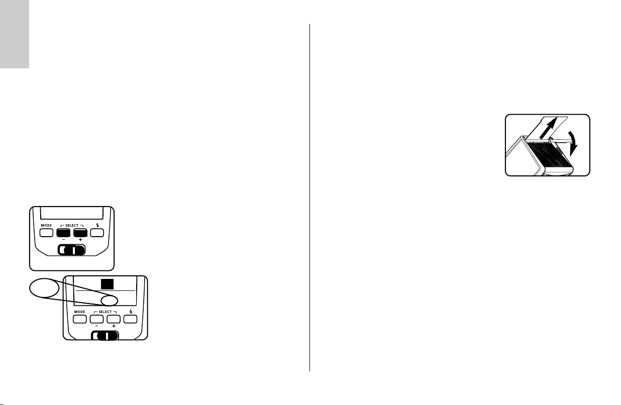
Batterien austauschen
Die Akkus/Batterien sind leer bzw. verbraucht, wenn die Blitzfolgezeit (Zeit vom
Auslösen eines Blitzes mit voller Lichtleistung, z.B. bei M, bis zum erneuten
Aufleuchten der Blitzbereitschaftsanzeige ) über 60 Sekunden ansteigt.
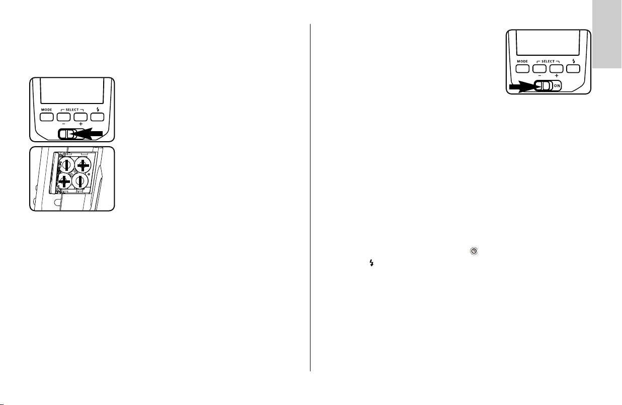
• Blitzgerät mit dem Hauptschalter ausschalten.
• Den Batteriefachdeckel nach vorne schieben und
aufklappen.
• Zuerst die Batterien einlegen, die dem Display zugewendet sind, danach die anderen einlegen.
Batteriefachdeckel schließen.
Achten Sie beim Einsetzen der Batterien bzw.
☞
Akkus auf die richtige Polarität gemäß den
Symbolen im Batteriefach. Vertauschte Pole
können zur Zerstörung des Gerätes führen!
Explosionsgefahr bei unsachgemäßem
Auswechseln der Batterien.
Ersetzen Sie immer alle Batterien durch gleiche,
hochwertige Batterien eines Herstellertyps mit
gleicher Kapazität! Verbrauchte Batterien bzw.
Akkus gehören nicht in den Hausmüll! Leisten
Sie einen Beitrag zum Umweltschutz und geben
Sie verbrauchte Batterien bzw. Akkus bei entsprechenden Sammelstellen ab!
3.3 Ein- und Ausschalten des Blitzgerätes
Das Blitzgerät wird mit dem Hauptschalter eingeschaltet. In der Stellung „ON“ ist das Blitzgerät eingeschaltet.
Zum Ausschalten den Hauptschalter in die linke
Position schieben.
Wird das Blitzgerät längere Zeit nicht gebraucht, so empfehlen wir:
☞
Blitzgerät mit dem Hauptschalter ausschalten und die Stromquellen
(Batterien, Akkus) entnehmen.
Ķ
3.4 Automatische Geräteabschaltung / Auto - OFF
Werksseitig ist das Blitzgerät so eingestellt, dass es ca. 10 Minuten -
• nach dem Einschalten,
• nach dem Betätigen einer Taste,
• nach dem Auslösen eines Blitzes,
• nach dem Antippen des Kameraauslösers,
• nach dem Ausschalten des Kamerabelichtungsmesssystems...
...in den Standby-Betrieb schaltet (Auto-OFF), um Energie zu sparen und die
Stromquellen vor unbeabsichtigtem Entladen zu schützen. Die aktive automatische Geräteabschaltung wird im Display mit angezeigt. Die Blitzbereitschaftsanzeige und die Anzeigen auf dem LC-Display verlöschen.
Im Slave-Betrieb ist die automatische Geräteabschaltung nicht aktiv.
☞
Die zuletzt benutzte Betriebseinstellung bleibt nach der automatischen Abschaltung
erhalten und steht nach dem Einschalten sofort wieder zur Verfügung. Das
Blitzgerät wird durch Drücken einer beliebigen Taste bzw. durch Antippen des
Kameraauslösers (Wake-Up-Funktion) wieder eingeschaltet.
Wenn das Blitzgerät längere Zeit nicht benötigt wird, sollte das Gerät
☞
grundsätzlich immer mit dem Hauptschalter ausgeschaltet werden!
Bei Bedarf kann die automatische Geräteabschaltung bereits nach 1 Minute
erfolgen oder ausgeschaltet werden (siehe 9.3).
5
Page 6
Ķ
4 LED-Anzeigen am Blitzgerät
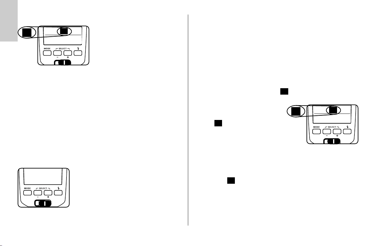
4.1 Blitzbereitschaftsanzeige
Bei aufgeladenem Blitzkondensator leuchtet am
Blitzgerät die Blitzbereitschaftsanzeige auf und
zeigt damit die Blitzbereitschaft an. Das bedeutet,
dass für die nächste Aufnahme Blitzlicht verwendet
✴
Wird eine Aufnahme gemacht, bevor im Kamerasucher die Anzeige für die
Blitzbereitschaft erscheint, so wird das Blitzgerät nicht ausgelöst, und die
Aufnahme unter Umständen falsch belichtet, falls die Kamera bereits auf die
Blitzsynchronzeit umgeschaltet hat (siehe 11.1).
4.2 Belichtungskontrollanzeige
✴
einstellen (z.B. anstatt Blende 11 die Blende 8) oder die Entfernung zum Motiv
bzw. zur Reflexfläche (z.B. beim indirekten Blitzen) verkleinern und die
Aufnahme wiederholen. Beachten Sie die Reichweitenanzeige im Display des
Blitzgerätes (siehe 5.2).
werden kann. Die Blitzbereitschaft wird auch an die
Kamera übertragen und sorgt im Kamerasucher für
eine entsprechende Anzeige (siehe 6).
Die Belichtungskontrollanzeige „o.k.“ leuchtet für
ca. 3 Sekunden, wenn die Aufnahme in den
TTL–Blitzbetriebsarten (TTL, Vorblitz-TTL, ADI-Messung;
siehe 7) richtig belichtet wurde!
Erfolgt keine Belichtungskontrollanzeige „o.k.“
nach der Aufnahme, so wurde die Aufnahme unterbe-
lichtet und Sie müssen die nächst kleinere Blendenzahl
5 Anzeigen am Display
Die meisten Kameras übertragen die Werte für ISO, Objektivbrennweite (mm)
und Blende an das Blitzgerät. Dieses passt seine erforderlichen Einstellungen
automatisch an. Es errechnet aus den Werten und seiner Leitzahl die maximale
Reichweite des Blitzlichtes. Blitzbetriebsart, Reichweite, Blende und
Zoom–Position des Hauptreflektors werden im Display des Blitzgerätes angezeigt.
Wird das Blitzgerät betrieben ohne dass es Daten von der Kamera erhalten hat
(z.B. wenn die Kamera ausgeschaltet ist), so wird nur die gewählte
Blitzbetriebsart, die Zoom-Position des Hauptreflektors und „Zoom“ angezeigt.
Die Anzeigen für Blende und Reichweite erfolgen erst, wenn das Blitzgerät die
erforderlichen Daten von der Kamera erhalten hat.
Anzeigen für Auto-Zoom, Blende und Reichweite erfolgen nur mit
☞
Kameras die Blenden- und ISO-Werte an das Blitzgerät übertragen!
Displaybeleuchtung
Bei jedem Tastendruck am Blitzgerät wird für ca. 10 Sek. die
Displaybeleuchtung des Blitzgerätes aktiviert. Beim Auslösen eines Blitzes durch
die Kamera oder durch die Handauslösetaste am Blitzgerät wird die
Displaybeleuchtung abgeschaltet.
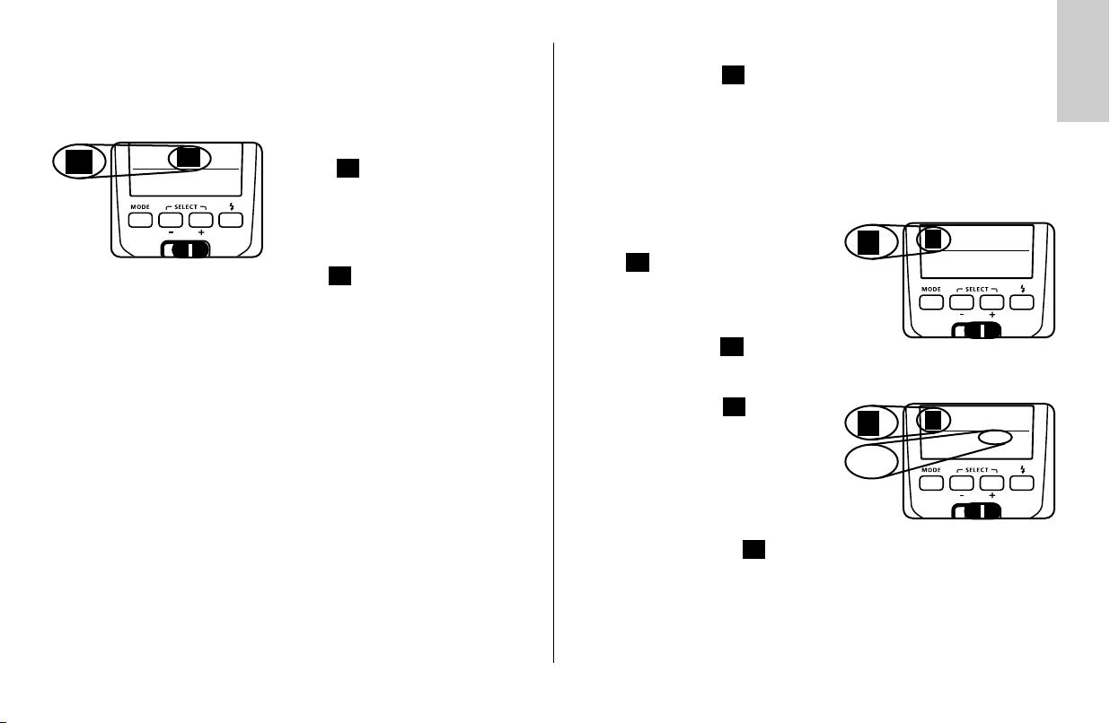
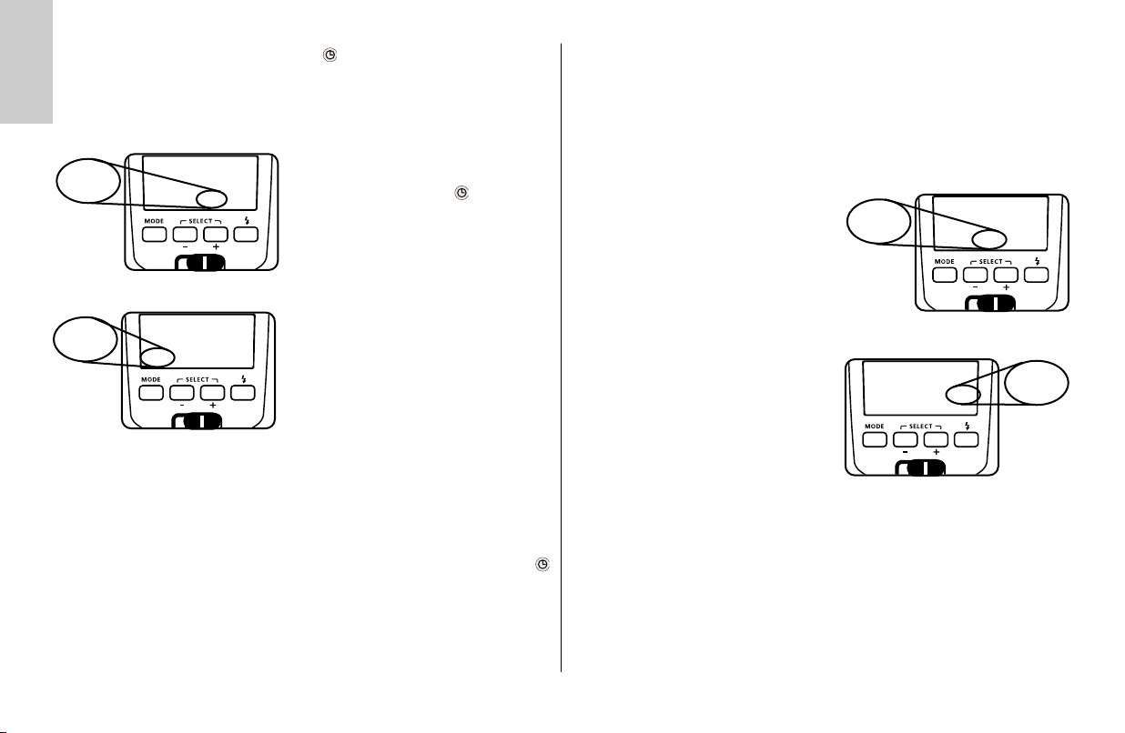
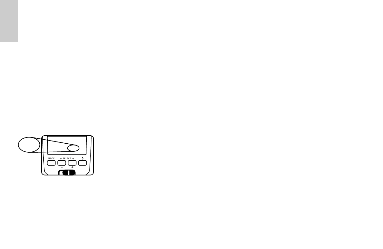
5.1 Anzeige der Blitzbetriebsart
Im Display wird die eingestellte
Blitzbetriebsart angezeigt. Dabei sind je nach
Kameratyp verschiedene Anzeigen für die jeweils
unterstützte TTL-Blitzbetriebsart
(z.B. , HSS) und den manuellen Blitzbetrieb ,
M
HSS möglich (siehe 7).
TTL
MTTLTTL
TTL
Zoom
m
13
mm
70
6
Page 7
5.2 Reichweitenanzeige
Beim Einsatz von Kameras die Daten für ISO, Objektivbrennweite und Blende
übertragen erfolgt am Display eine Reichweitenanzeige. Dazu muss ein
Datenaustausch zwischen Kamera und Blitzgerät stattgefunden haben, z.B.
durch antippen des Kameraauslösers. Die Reichweite kann entweder in Meter
(m) oder Feet (ft) angezeigt werden (siehe 9.6).
Es erfolgt keine Reichweitenanzeige wenn keine Daten von der Kamera
☞
übertragen werden;
- wenn der Reflektorkopf aus seiner Normalposition (nach oben oder seitwärts) abgeschwenkt ist.
- das Blitzgerät im Remote-Blitzbetrieb (Slave SL) arbeitet.
- Die Reichweitenanzeige blinkt, wenn der Reflektor nach unten
geschwenkt ist (siehe 10.3).
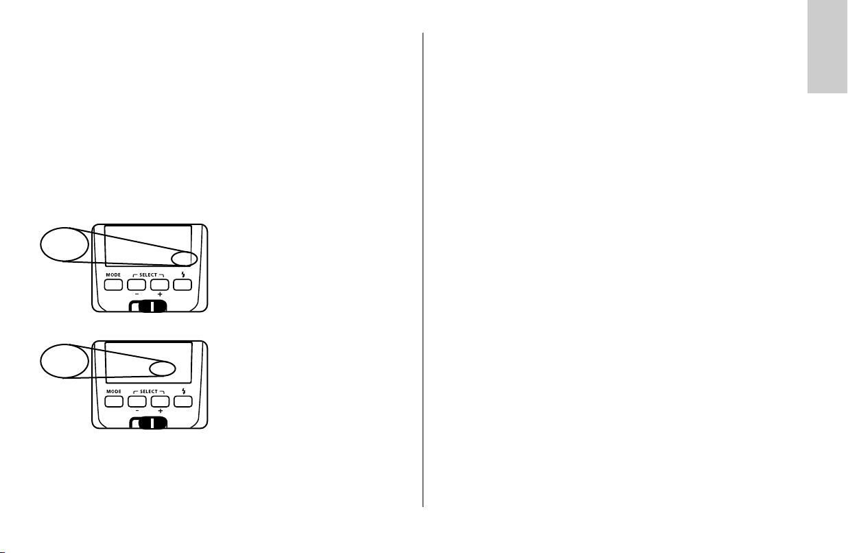
Reichweitenanzeige in TTL-Blitzbetriebsarten
13
m
TTL
Zoom
m
13
70
✴
z.B. bei sehr stark oder sehr schwach reflektierenden Objekten können die
Reichweite des Blitzgerätes beeinflussen.
Das Motiv sollte sich im Bereich von etwa 40% bis 70% des angezeigten Wertes
befinden. Damit wird der Elektronik genügend Spielraum zum Ausgleich gegeben. Der Mindestabstand zum Motiv sollte 10% des angezeigten Wertes nicht
unterschreiten um Überbelichtungen zu vermeiden! Die Anpassung an die
jeweilige Aufnahmesituation kann z.B. durch Ändern der Objektivblende
erreicht werden.
In den TTL-Blitzbetriebsarten (siehe 7.1) wird
im Display der Wert für die maximale
mm
Reichweite des Blitzlichtes angezeigt. Der
angezeigte Wert bezieht sich auf einen
Reflexionsgrad von 25% des Motivs, was für
die meisten Aufnahmesituationen zutrifft.
Starke Abweichungen des Reflexionsgrades,
Reichweitenanzeige im manuellen Blitzbetrieb M
Im manuellen Blitzbetrieb M wird im Display
der Entfernungswert angezeigt, der für eine
korrekte Blitzbelichtung des Motivs einzuhalten
ist. Die Anpassung an die jeweilige
Aufnahmesituation kann z.B. durch ändern der
Objektivblende oder durch Wahl einer manuellen Teillichtleistung (siehe 7.2) erreicht werden.
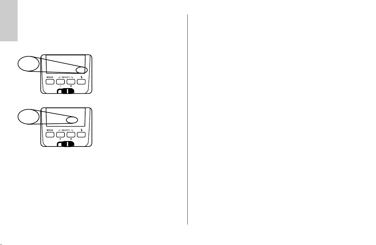
Überschreitung des Anzeigebereichs
Im Display werden Reichweiten bis maximal
199 m bzw. 199 ft angezeigt. Bei hohen
ISO-Werten (z.B. ISO 6400) und großen
Blendenöffnungen kann der Anzeigebereich
überschritten werden. Dies wird durch einen
Pfeil bzw. Dreieck hinter dem Entfernungswert
angezeigt.
6 Anzeigen im Kamerasucher
Je nach Kameratyp erfolgen im Kamerasucher verschiedene Anzeigen für den
Status des Blitzgerätes. Beachten Sie deshalb die Hinweise in der
Kamerabedienungsanleitung!
Beispiele für die Anzeigen im Kamerasucher:
• Das Blitzsymbol
Der Kondensator im Blitzgerät wird geladen.
Das Blitzgerät ist noch nicht blitzbereit.
• Das Blitzsymbol
Der Kondensator im Blitzgerät ist aufgeladen.
Das Blitzgerät ist einsatzbereit.
blinkt vor der Aufnahme:
leuchtet:
2,5
199
Ķ
M
m
Zoom
2,5
m
mm
35
✴
M
m
Zoom
199
m
mm
70
✴
7
Page 8
Ķ
7 Blitzbetriebsarten („Mode“)
TTL
TTL
Zoom
m
20
35
☛
Die Einstellung der Blitzbetriebsart erfolgt mit der Taste „Mode“ .
7.1 TTL-Betriebsarten
In den TTL-Blitzbetriebsarten erreichen Sie auf einfache Art sehr gute
Blitzlichtaufnahmen. In diesen Blitzbetriebsarten wird die
Blitzbelichtungsmessung von einem Sensor in der Kamera vorgenommen. Dieser
misst das vom Motiv reflektierte Licht durch das Objektiv (TTL = „Trough The
Lens“). Die Kamera ermittelt dabei automatisch die erforderliche Blitzleistung für
eine korrekte Belichtung der Aufnahme. Der Vorteil der TTL-Blitzbetriebsarten
liegt darin, dass alle Faktoren, welche die Belichtung beeinflussen
(Aufnahmefilter, Blenden- und Brennweitenänderungen bei Zoom-Objektiven,
Auszugsverlängerungen für Nahaufnahmen usw.), automatisch bei der
Regelung des Blitzlichtes berücksichtigt werden.
Bei einer korrekt belichteten Aufnahme leuchtet für ca.
3s die Belichtungskontrollanzeige (siehe 4.2).
☞
✴
Je nach Kameratyp stehen verschiedene
TTL–Blitzbetriebsarten, der manuelle
mm
Blitzbetrieb und die Kurzzeitsynchronisationn
HSS zur Verfügung. Zum Einstellen der
Blitzbetriebsart muss deshalb vorher ein
Datenaustausch zwischen Blitzgerät und
Kamera stattfinden, z.B. durch Antippen des
Kameraauslösers.
Beachten Sie ob es für Ihren Kameratyp
Einschränkungen hinsichtlich des ISO-Wertes für
den TTL-Blitzbetrieb gibt (z.B. ISO 64 bis ISO
1000; siehe Kamerabedienungsanleitung)! Zum
Testen der TTL-Funktion muss sich bei analogen
Kameras ein Film in der Kamera befinden!
Vorblitz-TTL und ADI-Messung
Vorblitz-TTL und ADI-Messung sind digitale TTL-Blitzbetriebsarten und
Weiterentwicklungen des TTL-Blitzbetriebes analoger Kameras. Bei der
Aufnahme wird vor der eigentlichen Belichtung ein fast nicht erkennbarer
Messvorblitz vom Blitzgerät abgegeben. Das reflektierte Licht des Messvorblitzes
wird von der Kamera ausgewertet. Entsprechend der Auswertung wird die
nachfolgende Blitzbelichtung von der Kamera an die Aufnahmesituation angepasst (näheres siehe Kamerabedienungsanleitung). Bei der ADI-Messung gehen
zusätzlich Entfernungsdaten des Objektivs in die Blitzbelichtung mit ein. Die
Auswahl bzw. Einstellung der Betriebsarten Vorblitz-TTL und ADI-Messung
erfolgt an der Kamera (siehe Kamerabedienungsanleitung).
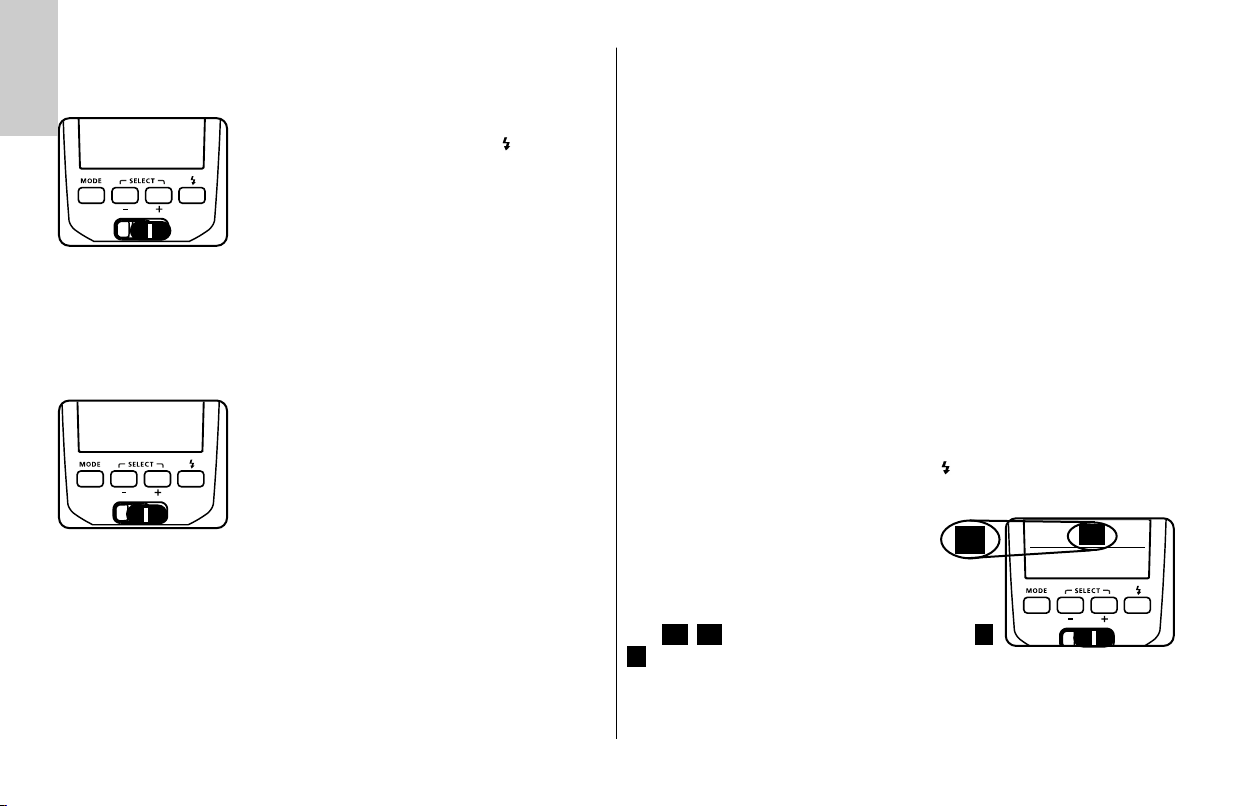
Das Blitzgerät muss in die Blitzbetriebsart „ “ geschaltet werden.
Einstellvorgang
• Taste „Mode“ so oft drücken, bis im
Display „ “ blinkt.
Die Einstellung wird sofort wirksam.
TTL
TTL
TTL
TTL
Zoom
m
20
mm
35
☛
Nach ca. 5 Sekunden hört die Anzeige auf zu blinken und die Einstellung wird
automatisch gespeichert.
Im Display wird „ “ angezeigt.
Eine besondere Anzeige für Vorblitz-TTL bzw. ADI–Messung am Blitzgerät
erfolgt nicht.
TTL
8
Page 9
TTL-Blitzbetrieb
Diese analoge TTL-Blitzbetriebsart wird von älteren analogen Kameras unterstützt. Es ist der normale TTL-Blitzbetrieb (TTL-Blitzbetrieb ohne Vorblitz).
Einstellvorgang
TTL
☛
Automatischer Aufhellblitzbetrieb in den TTL-Betriebsarten
Bei den meisten Kameratypen wird in der Programmautomatik P, und den Varibzw. Motiv-Programmen bei Tageslicht der automatische Aufhellblitzbetrieb
aktiviert (siehe Kamerabedienungsanleitung).
Mit dem Aufhellblitz können Sie lästige Schatten beseitigen und bei
Gegenlichtaufnahmen eine ausgewogene Belichtung zwischen Motiv und
Bildhintergrund erreichen. Ein computergesteuertes Meßsystem der Kamera
sorgt für die geeignete Kombination von Verschlusszeit, Arbeitsblende und
Blitzleistung.
Achten Sie darauf, dass die Gegenlichtquelle nicht direkt ins Objektiv
☞
scheint. Das TTL-Meßsystem der Kamera wird dadurch getäuscht!
Eine Einstellung oder Anzeige für den automatischen Aufhellblitzbetrieb am
Blitzgerät erfolgt nicht.
TTL
Zoom
m
20
Im Display wird das Symbol „ “ angezeigt.
35
• Taste „Mode“ so oft drücken, bis im
mm
Display „ “ blinkt.
Die Einstellung wird sofort wirksam.
Nach ca. 5 Sekunden hört die Anzeige auf
zu blinken und die Einstellung wird automatisch gespeichert.
TTL
TTL
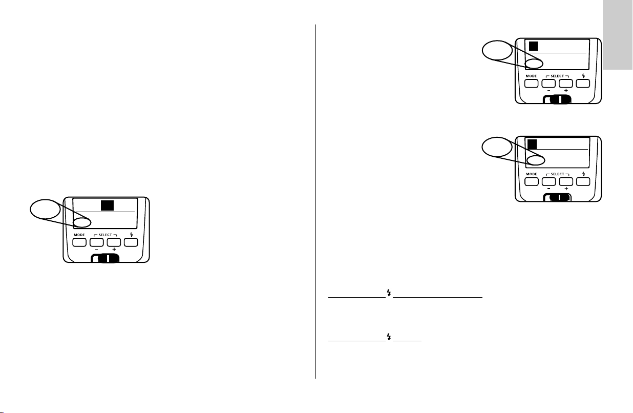
7.2 Manueller Blitzbetrieb
Im manuellen Blitzbetrieb wird vom Blitzgerät ungeregelt die volle Energie
abgestrahlt, sofern keine Teillichtleistung eingestellt ist. Die Anpassung an die
Aufnahmesituation kann z.B. durch die Blendeneinstellung an der Kamera oder
durch Auswahl einer geeigneten manuellen Teillichtleistung erfolgen. Der
Einstellbereich erstreckt sich von P 1/1 - P1/128 bzw. P 1/1 - P 1/32 bei HSS
(siehe 7.3). Am Display wird die Entfernung angezeigt, bei der das Motiv korrekt belichtet wird (siehe 5.2).
Einstellvorgang
• Taste „Mode“ so oft drücken, bis im
Display blinkt.
Die Einstellung wird sofort wirksam.
Nach ca. 5 Sekunden hört die Anzeige auf zu blinken
und die Einstellung wird automatisch gespeichert. Im
Display wird das Symbol angezeigt.
M
M
M
M
M
Zoom
m
17
35
Ķ
mm
☛
Manuelle Teillichtleistungen
Im Manuellen Blitzbetrieb mit den Tasten
+ und – die gewünschte Teillichtleistung einstellen. Die Einstellung wird sofort wirksam
und automatisch gespeichert.
Die Entfernungsanzeige wird automatisch der
Teillichtleistung angepasst (siehe 5.2).
Verschiedene Kameratypen unterstützen den
☞
manuellen Blitzbetrieb nur in der Kamerabetriebsart Manuell M!
In anderen Kamerabetriebsarten erfolgt eine Fehlermeldung im Display
und die Auslösung wird verriegelt
M
M
8,6
M
P 1/4
Zoom
m
mm
35
P1/4
M
☛
9
Page 10
7.3 Automatische Kurzzeitsynchronisation (HSS)
Ķ
Verschiedene Kameras unterstützen die Automatische Kurzzeitsynchronisation
(siehe Kamerabedienungsanleitung). Mit dieser Blitzbetriebsart ist es möglich,
auch bei kürzeren Verschlusszeiten als der Blitzsynchronzeit ein Blitzgerät einzusetzen. Interessant ist diese Betriebsart z.B. bei Portrait-Aufnahmen in sehr hellem Umgebungslicht, wenn durch eine weit geöffnete Blende (z.B. F 2,0) die
Schärfentiefe begrenzt werden soll! Das Blitzgerät unterstützt die
Kurzzeitsynchronisation in den TTL-Blitzbetriebsarten und M.
Physikalisch bedingt, wird jedoch durch die Kurzzeitsynchronisation die
Leitzahl, und damit auch die Reichweite des Blitzgerätes zum Teil erheblich eingeschränkt! Beachten Sie daher die Reichweitenanzeige am Display des
Blitzgerätes! Die Kurzzeitsynchronisation wird automatisch ausgeführt, wenn an
der Kamera manuell oder automatisch durch das Belichtungsprogramm eine
kürzere Verschlusszeit als die Blitzsynchronzeit eingestellt ist.
Beachten Sie, dass die Leitzahl des Blitzgerätes bei der
☞
Kurzzeitsynchronisation zusätzlich von der Verschlusszeit abhängig ist:
Je kürzer die Verschlusszeit desto geringer die Leitzahl!
Einstellvorgang
TTL
TTL
HSS
m
17
HSS
Zoom
35
☛
Im Display wird „ HSS“ bzw. „ HSS“ angezeigt.
Zum Löschen der Kurzzeitsynchronisation die Taste „Mode“ so oft drücken bis
das Symbol „HSS“ erlischt.
• Taste „Mode“ so oft drücken, bis im
mm
Display „ HSS“ bzw. „ HSS“
blinkt.
Die Einstellung wird sofort wirksam.
Nach ca. 5 Sekunden hört die Anzeige
auf zu blinken und die Einstellung wird
automatisch gespeichert.
MTTL
MTTL
8 Manuelle Blitzbelichtungskorrektur
Die Blitzbelichtungsautomatik der meisten Kameras ist auf einen Reflexionsgrad
von 25 % (durchschnittlicher Reflexionsgrad von Blitzmotiven) abgestimmt. Ein
dunkler Hintergrund, der viel Licht absorbiert oder ein heller Hintergrund, der
stark reflektiert (z.B. Gegenlichtaufnahmen), können zu Über- bzw.
Unterbelichtung des Motivs führen.
Um den oben genannten Effekt zu kompensieren, kann die Blitzbelichtung manuell
mit einem Korrekturwert der Aufnahme angepasst werden. Die Höhe des
Korrekturwertes ist vom Kontrast zwischen Motiv und Bildhintergrund abhängig!
Tipp:
Dunkles Motiv vor hellem Bildhintergrund: Positiver Korrekturwert.
Helles Motiv vor dunklem Bildhintergrund: Negativer Korrekturwert.
Die Einstellung des Korrekturwertes erfolgt an der Kamera (siehe Kamera-
bedienungsanleitung).
Eine besondere Anzeige am Blitzgerät erfolgt nicht.
Eine Belichtungskorrektur durch Verändern der Objektivblende ist nicht
☞
möglich, da die Belichtungsautomatik der Kamera die geänderte Blende
wiederum als normale Arbeitsblende betrachtet. Beim Einstellen eines
Korrekturwertes kann sich die Reichweitenanzeige im Display ändern
und dem Korrekturwert angepasst werden (abhängig von Kameratyp)!
Vergessen Sie nicht die TTL-Blitzbelichtungskorrektur nach der Aufnahme an der
Kamera wieder zu löschen!
Achtung: Stark reflektierende Gegenstände im Bild des Motivs können die
Belichtungsautomatik der Kamera stören. Die Aufnahme wird dann
unterbelichtet. Reflektierende Gegenstände entfernen oder einen
positiven Korrekturwert einstellen.
10
Page 11
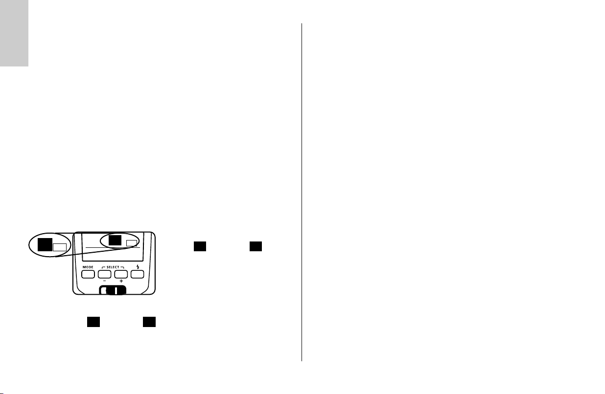
9 Sonderfunktionen („Select“)
Je nach Kameratyp stehen verschiedene Sonderfunktionen zur Verfügung. Zum
Aufrufen und Einstellen der Sonderfunktionen muss deshalb vorher ein
Datenaustausch zwischen Blitzgerät und Kamera stattfinden, z.B. durch
Antippen des Kameraauslösers.
Das Aufrufen der einzelnen Sonderfunktionen erfolgt
mit der Tastenkombination „Select“, das heißt, dass
die Tasten – bzw. + gleichzeitig betätigt werden müssen. Die der Sonderfunktion zugehörigen und
gewünschten Einstellungen werden anschließend ein-
☛
☛
Die Einstellung muss unmittelbar nach dem Aufrufen der Sonderfunktion
☞
erfolgen, da das Blitzgerät sonst nach einigen Sekunden automatisch
wieder in den normalen Blitzbetrieb wechselt!
9.1 Motorzoom-Hauptreflektor („Zoom“)
Der Motorzoom-Hauptreflektor des Blitzgerätes kann Objektivbrennweiten
ab 24 mm (Kleinbild-Format) ausleuchten. Durch Einsatz der integrierten
Weitwinkel-Streuscheibe erweitert sich die Ausleuchtung auf 12 mm.
Auto-Zoom.
Wenn das Blitzgerät mit einer Kamera betrieben wird, die Daten der
Objektivbrennweite überträgt, passt sich die Zoom-Position des Hauptreflektors
automatisch der Objektivbrennweite an. Nach dem Einschalten des Blitzgerätes
wird im Display „Zoom“ und die aktuelle Zoom-Position des Hauptreflektors
angezeigt.
Die automatische Anpassung erfolgt für Objektivbrennweiten ab 24 mm. Wird
eine Brennweite von weniger als 24 mm eingesetzt, so blinkt im Display die
Anzeige „24“ als Warnhinweis, dass die Aufnahme nicht vollständig ausgeleuchtet werden kann.
zeln mit der Taste – bzw. + durchgeführt.
☞
Auf Wunsch kann die Position des Hauptreflektors manuell verstellt werden
um bestimmte Beleuchtungseffekte zu erzielen (z.B. Spot-Effekt usw.).
Manueller Zoom-Betrieb
Bei Kameras die keine Daten der Objektivbrennweiten übertragen muss, die
Zoom-Position des Hauptreflektors manuell an die Objektivbrennweite angepasst werden. Der Auto-Zoom-Betrieb ist in diesem Fall nicht möglich!
Nach dem Einschalten des Blitzgerätes wird im Display „Zoom“ und die aktuelle
Zoom–Position des Hauptreflektors angezeigt.
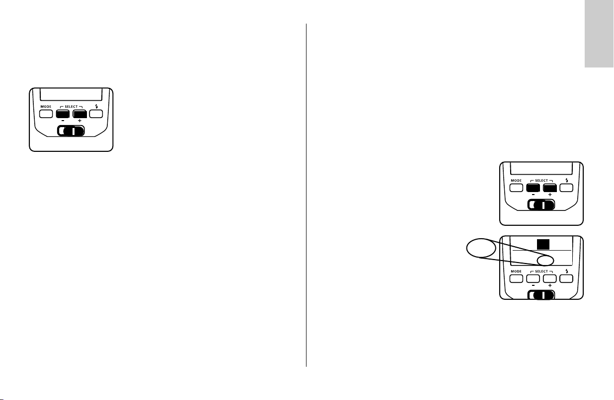
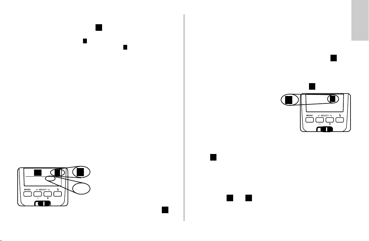
Einstellvorgang
• Tastenkombination „Select“ so oft drücken, bis
„Zoom“ blinkend neben der Zoom-Position (mm)
angezeigt wird.
• Mit den Tasten + und – die gewünschte
Nach ca. 5 Sekunden hört die Anzeige auf zu blinken und die Einstellung wird
automatisch gespeichert.
Die automatische Anpassung erfolgt nicht, wenn der Hauptreflektor
geschwenkt ist, wenn die Weitwinkel-Streuscheibe ausgezogen oder
ein Mecabounce (Zubehör) montiert ist.
☛
☛
20
m
TTL
M.Zoom
35
☛
Einstellung vornehmen. Im Display wechselt die blinkende Anzeige dabei auf
„M.Zoom“ für den manuellen Zoom-Betrieb.
Folgende Zoom-Positionen für den Hauptreflektor
sind möglich:
24 - 28 - 35 - 50 - 70 - 85 - 105 mm (KleinbildFormat).
Die Einstellung wird sofort wirksam.
M Zoom
Ķ
mm
11
Page 12
Ķ
Wenn die Kamera die Daten der Objektivbrennweite an das Blitzgerät
☞
überträgt und eine manuelle Zoomverstellung dazu führt, dass die
Aufnahme vom Hauptreflektor nicht vollständig ausgeleuchtet wird (z.B.
bei Spot-Effekt), blinkt die Anzeige der Zoom-Position des
Hauptreflektors zur Warnung!
Tipp:
Wenn Sie nicht immer die volle Leitzahl und Reichweite des Blitzgerätes benöti-
gen, können Sie die Hauptreflektor-Position auf der Anfangsbrennweite des
Zoomobjektives belassen. Damit ist garantiert, dass die Bildränder immer vollständig ausgeleuchtet werden. Sie sparen sich damit die fortwährende
Anpassung an die Objektivbrennweite.
Beispiel: Sie benutzen ein Zoomobjektiv mit einem Brennweitenbereich von
35 mm bis 105 mm. In diesem Beispiel stellen Sie die Position des
Hauptreflektors des Blitzgerätes auf 35 mm.
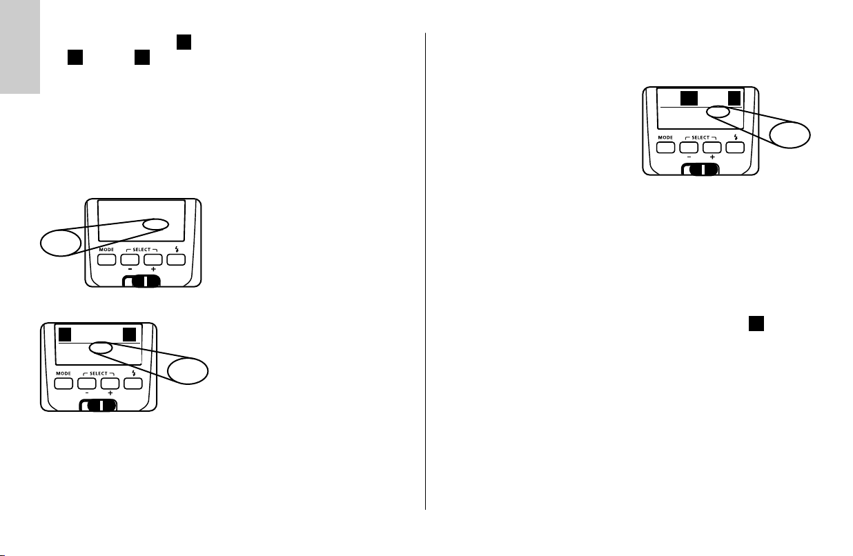
Rückstellen auf Auto-Zoom
• Kameraauslöser antippen, damit ein Datenaustausch zwischen Blitzgerät und Kamera stattfindet.
• Tastenkombination „Select“ so oft drücken, bis
„M.Zoom“ blinkend neben der Zoom-Position (mm)
angezeigt wird.
☛
☛
14
m
TTL
Zoom
35
☛
Zoom
Nach ca. 5 Sekunden hört die Anzeige auf zu blinken und die Einstellung wird
• Die Taste + so oft drücken, bis die
105 mm - Position überschritten wird.
mm
Dabei wechselt die blinkende Anzeige von
„M.Zoom“ auf „Zoom“ (= Auto-ZoomBetrieb) und die Zoom-Position des
Hauptreflektors wird automatisch der
Objektivbrennweite angepasst.
Die Einstellung wird sofort wirksam.
automatisch gespeichert.
Die Rückstellung von manuellem Zoom-Betrieb auf Auto-Zoom-Betrieb
☞
erfolgt auch, wenn das Blitzgerät erneut mit dem Hauptschalter eingeschaltet wird.
Weitwinkelstreuscheibe
Mit der integrierten Weitwinkelstreuscheibe können Brennweiten ab 12 mm
ausgeleuchtet werden (Kleinbild-Format).
Weitwinkelstreuscheibe aus dem Hauptreflektor
nach vorne bis zum Anschlag herausziehen und loslassen. Die Weitwinkelstreuscheibe klappt automatisch nach unten. Der Hauptreflektor wird automatisch
in die erforderliche Position gesteuert. Am Display
werden die Entfernungsangaben und der Zoomwert
auf 12 mm korrigiert.
Die automatische Anpassung des Motorzoom-Hauptreflektor erfolgt
☞
nicht bei der Verwendung der Weitwinkelstreuscheibe.
Zum Einschieben die Weitwinkelscheibe um 90° nach oben klappen und
vollständig einschieben.
Mecabounce 58-90
Wenn der Mecabounce 58-90 (Sonderzubehör; siehe 17) am Hauptreflektor
des Blitzgerätes montiert ist, wird der Hauptreflektor automatisch in die erforderliche Position gesteuert. Die Entfernungsangaben und der Zoomwert werden
auf 16 mm korrigiert.
Die automatische Anpassung des Motorzoom-Hauptreflektor erfolgt
☞
nicht bei der Verwendung eines Mecabounce.
Die gleichzeitige Verwendung von Weitwinkelstreuscheibe und
☞
Mecabounce ist nicht möglich.
12
Page 13
9.2 Der drahtlose Remote-Betrieb
9.2.1 Remote-Slave-Blitzbetrieb ( )
Das Blitzgerät unterstützt das drahtlose Sony-Remote-System in den
Betriebsarten „CTRL“ und „CTRL “, abhängig vom verwendeten
Kamerasystem. Die Betriebsarten „CTRL“ und „CTRL “ werden automatisch
erkannt. Die Slave-Blitzgeräte arbeiten immer in der Gruppe „RMT“. Der
Aufbau kann grundsätzlich durch Drücken der Taste „AEL“ an der Kamera
geprüft werden. Das Slave-Blitzgerät muss mit einem zeitverzögerten Blitz antworten. Dabei können ein oder mehrere Slave-Blitzgeräte vom Blitzgerät an der
Kamera, das als Controller-Blitzgerät arbeitet, drahtlos ferngesteuert werden.
Die Slave-Blitzgeräte müssen mit dem integrierten Sensor für den RemoteBetrieb das Licht des Controller-Blitzgerätes empfangen können.
Der Remote-Slave-Blitzbetrieb wird nur von den digitalen
☞
Spiegelreflex–Kameras unterstützt!
Zum Einstellen des Remote–Slave–Blitzbetriebes gibt es zwei Möglichkeiten.
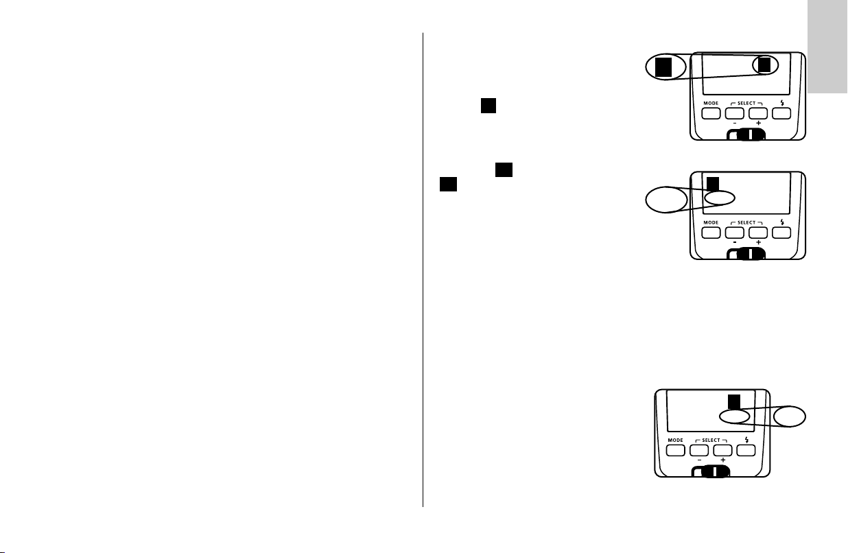
Einstellvorgang für den Remote–Slave–Blitzbetrieb (Möglichkeit 1)
Das integrierte Blitzgerät der Kamera (Controller-Blitzgerät) vollständig einklappen
•
und Blitzgerät (mecablitz 50AF-1 digital) auf die Kamera montieren (siehe 3.1).
• Kamera und Slave-Blitzgerät einschalten. Zum Aktivieren des
Remote–Slave–Betriebes die Kamera in den drahtlosen Remote-Blitzbetrieb
schalten („Wireless“ bzw. „WL“; siehe Kamerabedienungsanleitung).
SLTTL
CH 1
Zoom
mm
35
SL
CH 1
☛
SL
+
+
• Kameraauslöser antippen, damit ein
Datenaustausch zwischen Kamera und
Blitzgerät stattfindet. Das Blitzgerät wird
dabei automatisch in den Remote-SlaveBlitzgerät geschaltet. Gleichzeitig werden
Kamera und Blitzgerät auf den gleichen
Remote-Kanal geschaltet (siehe unten).
Im Display des Blitzgerätes wird
angezeigt.
SL
Deaktivieren des Remote-Slave-Blitzbetriebes:
• Bei montiertem Blitzgerät an der Kamera den drahtlosen Remote-Blitzbetrieb
(„Wireless“ bzw. „WL“) deaktivieren, bzw. in den normalen Blitzbetrieb
umschalten.
• Kameraauslöser antippen, damit ein Datenaustausch zwischen Kamera und
Blitzgerät stattfindet. Das Blitzgerät wird dabei automatisch in den normalen
Blitzbetrieb geschaltet. Im Display des Blitzgerätes wird die Anzeige
gelöscht.
Der Remote-Slave-Blitzbetrieb kann auch ohne Kamera aktiviert und
deaktiviert werden (Möglichkeit 2)
• Tastenkombination „Select“ so oft drücken, bis im Display blinkt.
• Mit den Tasten + und — die gewünschte
Einstellung vornehmen.
– Bei der Anzeige „On“ ist der
– Bei der Anzeige „OFF“ ist der
Nach ca. 5 Sekunden hört die Anzeige auf zu blinken und die Einstellung wird
automatisch gespeichert. Nach der Aktivierung des Remote-Slave-Betriebes wird
im Display angezeigt.
Einstellung der Remote-Betriebsart
Vom Sony-Remote-Betrieb werden die Blitzbetriebsarten TTL und Manuell M,
sowie die Kurzzeitsynchronisation HSS unterstützt. Die Auswahl der
Remote–Betriebsart erfolgt mit der Taste „Mode“.
Dazu die Taste „Mode“ so oft drücken, bis das Symbol für die gewünschte
Remote-Betriebsart bzw. blinkt.
Die Einstellung wird sofort wirksam. Nach ca. 5 Sekunden hört die Anzeige auf
zu blinken und die Einstellung wird automatisch gespeichert.
Remote-Slave-Betrieb aktiviert.
Remote-Slave-Betrieb deaktiviert.
Die Einstellung wird sofort wirksam.
SL
MTTL
SL
SL
☛
Ķ
SL
SL
On
☛
13
Page 14
Ķ
Im Remote-Blitzbetrieb lässt sich die Kurzzeitsynchronisation HSS
☞
( HSS bzw. HSS) nicht am Slave-Blitzgerät einstellen. Die
Kurzzeitsynchronisation wird am Slave-Blitzgerät beim Abblitzen bei
Bedarf automatisch für die Dauer der Aufnahme aktiviert, wenn an der
Kamera eine Verschlusszeit eingestellt wird, die kürzer als die
Blitzsynchronzeit der Kamera ist (siehe Kamerabedienungsanleitung)!
An der Kamera lassen sich im Remote-Betrieb nur dann kürzere
Verschlusszeiten als die Blitzsynchronzeit einstellen, wenn das sich das
Slave–Blitzgerät nicht auf der Kamera befindet und die Kamera in die
Remote–Betriebsart „WL“ (wireless) geschaltet ist.
P1/4
☛
SLM
EV CH 1
Zoom
mm
35
☛
Die eingestellte Teillichtleistung kann durch wiederholtes Drücken der
☞
Tastenkombination „Select“ aufgerufen bzw. angezeigt werden. Die
Auswahl der Teillichtleistung kann bei Bedarf anschließend mit den
Tasten + und – geändert werden.
SL
MTTL
In der Remote-Betriebsart Manuell M kann
P 1/4
☛
• Mit den Tasten + und – die gewünschte Einstellung
tisch gespeichert. Nach dem Einstellen einer
Teillichtleistung blinkt im Display „EV“ und zeigt damit
an, dass eine Teillichtleistung eingestellt ist.
zur Anpassung der Lichtleistung eine
Teillichtleistung eingestellt werden:
• Tastenkombination „Select“ so oft drücken,
bis P und die manuelle Teillichtleistung
angezeigt wird.
vornehmen. Einstellungen von P 1/1
(volle Lichtleistung) bis P 1/128) sind möglich.
Die Einstellung wird sofort wirksam.
EV
Nach ca. 5 Sekunden hört die Anzeige auf
zu blinken und die Einstellung wird automa-
Einstellung des Remote-Kanals
Damit sich mehrere Remote-Systeme im gleichen Raum nicht gegenseitig stören
stehen vier unabhängige Remote-Kanäle (CH 1, 2, 3 oder 4) zur Verfügung.
• Bei aktiviertem Remote-Slave-Betrieb die
Tastenkombination „Select“ so oft
drücken, bis im Display „CH“
(= Remote-Kanal) blinkt.
• Mit den Tasten + und – die gewünschte
Einstellung vornehmen. Die Auswahl von
Kanal 1, 2, 3 oder 4 ist möglich.
Die Einstellung wird sofort wirksam.
Nach ca. 5 Sekunden hört die Anzeige auf zu blinken und die Einstellung wird
automatisch gespeichert.
Controller- und Slave-Blitzgeräte die zum gleichen Remote-System gehören,
müssen alle auf den gleichen Remote-Kanal eingestellt werden. Die Einstellung
des Remote-Kanals am Controller (integriertes Blitzgerät der Kamera) erfolgt
automatisch bei einem Datenaustausch, wenn sich das Slave-Blitzgerät auf der
Kamera befindet und der Kameraauslöser angetippt wird.
Nach der Aktivierung des Remote-Slave-Betriebes werden im Display , die
gewählte Remote-Betriebsart, die Reflektorposition und der Remote-Kanal (CH)
angezeigt. Wenn eine manuelle Teillichtleistung eingestellt ist blinkt zusätzlich
„EV“.
Im Remote-Slave-Betrieb erfolgt keine Reichweitenanzeige!
☞
Der Hauptreflektor des Blitzgerätes wird im Remote-Slave-Betrieb automatisch in die Position 24 mm gesteuert um ein möglichst breites Bildfeld auszuleuchten. Die Position des Hauptreflektors kann auf Wunsch manuell verändert
werden (siehe 9.1).
☛
SLTTL
CH 3
Zoom
mm
35
☛
CH 3
SL
14
Page 15
Ķ
Prüfen des Remote-Blitzbetriebes
• Slave-Blitzgerät von der Kamera abnehmen und das integrierte Blitzgerät der
Kamera aufklappen.
• Slave-Blitzgerät so positionieren, wie für die spätere Aufnahme gewünscht.
Verwenden Sie zum Aufstellen des Slave-Blitzgerätes einen BlitzgeräteStandfuß S60 (Sonderzubehör; siehe 17).
• Blitzbereitschaft von Slave-Blitzgerät und integriertem Blitzgerät der Kamera
abwarten. Ist beim Slave-Blitzgerät die Blitzbereitschaft erreicht, blinkt dessen
AF-Messblitz .
• An der Kamera einen Testblitz auslösen, z.B. mit der AEL-Taste (abhängig
vom Kameratyp; siehe Kamerabedienungsanleitung).
• Das Slave-Blitzgerät antwortet verzögert mit einem Testblitz. Wenn das Slave-
Blitzgerät keinen Testblitz abgibt korrigieren Sie die Position des SlaveBlitzgerätes damit dieses mit dem Sensor das Licht des ControllerBlitzgerätes empfangen kann bzw. verringern Sie den Abstand zwischen
Controller- und Slave-Blitzgerät.
Nach erfolgreichem Testblitzbetrieb können Sie mit den Aufnahmen beginnen.
•
9.2.2 SERVO-Betrieb
Der SERVO-Betrieb ist ein einfacher Slave-Betrieb mit Vorblitzunterdrückung,
bei dem das Slave-Blitzgerät immer einen Blitz abgibt, sobald es einen
Lichtimpuls des Kamerablitzgerätes empfängt.
Einstellvorgang für den SERVO–Blitzbetrieb
• Stellen Sie an der Kamera eine Betriebsart
TTL ein.
• Tastenkombination „Select“ so oft drücken, bis im
Display blinkt.
• Mit der Taste + den Remote-Slave-Betrieb aktiviert.
• Nochmals die Taste + drücken und den
SERVO–Betrieb einschalten. Im SERVO-Betrieb ist generell nur der manuelle
Blitzbetrieb möglich. Der manuelle Blitzbetrieb
schalten des SERVO–Betriebes automatisch
eingestellt.
• Mit den Tasten + und — kann eine Teillichtleistung
eingestellt werden.
• Blitzbereitschaft aller beteiligten Blitzgeräte abwarten. Ist bei den
Slave–Blitzgeräten die Blitzbereitschaft erreicht, blinkt der AF–Messblitz .
☞
☞
SERVO–Blitzbetrieb ausschalten
• Tastenkombination „Select“ so oft drücken,
bis im Display „SERVO“ blinkt.
• Taste — zweimal drücken und den
SERVO–Betrieb ausschalten.
SL
M
M
wird nach dem Ein-
Slave-Gruppen und Remote-Kanäle können im
SERVO-Betrieb nicht eingestellt werden.
Das Kamerablitzgerät darf nicht im Remote-Betrieb arbeiten
SL
SERVO
M
SERVO P 1/1
SL
On
☛
☛
Zoom 24 mm
☛
SL
OFF
OFF
☛
15
Page 16
Ķ
Ȅ
Ȅ
9.3 Automatische Geräteabschaltung
Die Automatische Geräteabschaltung kann so eingestellt werden, dass sie nach
10 Minuten oder 1 Minute erfolgt, bzw. deaktiviert ist.
Einstellvorgang
• Tastenkombination „Select“ so oft
Ȅ
10min
☛
10min
10min
– Bei der Anzeige „OFF“ ist die automatische
Geräteabschaltung deaktiviert.
Die Einstellung wird sofort wirksam.
Nach ca. 5 Sekunden hört die Anzeige auf zu blinken und die Einstellung wird
automatisch gespeichert.
Nach der Aktivierung der automatischen Geräteabschaltung wird im Display
angezeigt.
OFF
☛
OFF
☛
drücken, bis das Symbol blinkt.
• Mit den Tasten + und — die gewünschte
Einstellung vornehmen.
– Bei der Anzeige „10min“ ist die automa-
tische Geräteabschaltung aktiviert und
erfolgt nach 10 Minuten.
– Bei der Anzeige „1min“ ist die automati-
sche
Geräteabschaltung aktiviert und erfolgt
nach 1 Minute.
9.4 Einstelllicht („ML“)
Beim Einstelllicht (ML = Modelling Light) handelt es sich um ein
Stroboskop–Blitzlicht mit hoher Frequenz. Bei einer Dauer von ca. 5 Sekunden
entsteht der Eindruck eines Quasi-Dauerlichtes. Mit dem Einstelllicht kann die
Lichtverteilung und Schattenbildung bereits vor einer Aufnahme beurteilt werden. Das Einstelllicht wird mit der Handauslösetaste ausgelöst.
Einstellvorgang
• Tastenkombination „Select“ so oft
drücken, bis im Display „ML“ blinkt.
• Mit den Tasten + und — die gewünschte Einstellung
vornehmen.
– Bei der Anzeige „ML ON“ ist das
Einstelllicht aktiviert.
– Bei der Anzeige „ML OFF“ ist das
Einstelllicht deaktiviert.
Die Einstellung wird sofort wirksam.
ML
ML
☛
On
OFF
ML
☛
On
☛
Nach ca. 5 Sekunden hört die Anzeige auf zu blinken und die Einstellung wird
automatisch gespeichert.
Nach der Aktivierung der Einstelllicht-Funktion wird im Display „ML“ angezeigt.
16
Page 17
9.5 Extended-Zoom-Betrieb („Ex“)
Beim Extended-Zoom-Betrieb wird die Zoom-Position des Hauptreflektors um
eine Stufe gegenüber der Objektivbrennweite der Kamera reduziert.
Die daraus resultierende erweiterte und großflächigere Ausleuchtung sorgt in
Räumen für zusätzliches Streulicht (Reflexionen) und damit für eine weichere
Blitzlicht–Ausleuchtung.
Beispiel:
Die Objektivbrennweite an der Kamera beträgt 50 mm.
Im Extended-Zoom-Betrieb steuert das Blitzgerät den Hauptreflektor auf die
Zoom-Position 35 mm. Im Display wird weiter 50 mm angezeigt.
Einstellvorgang
Ex
On
OFF
☛
☛
On
• Tastenkombination „Select“ so oft
Ex
Ex
drücken, bis nur „Ex“ blinkend angezeigt
wird.
• Mit den Tasten + und — die gewünschte
Einstellung vornehmen.
– Bei der Anzeige „Ex On“ ist der
Extended-Zoom-Betrieb aktiviert.
– Bei der Anzeige „Ex Off“ ist der
Extended-Zoom-Betrieb deaktiviert.
Die Einstellung wird sofort wirksam.
Systembedingt wird der Extended-Zoom-Betrieb für Objektivbrennweiten
☞
ab 28 mm (Kleinbild-Format) unterstützt. Die Kamera muss mit einem
CPU-Objektiv ausgerüstet sein und die Daten für die Objektivbrennweite
an das Blitzgerät liefern.
9.6 Meter-Feet-Umschaltung („m“ / „ft“)
Die Reichweitenanzeige im Display des Blitzgerätes kann wahlweise in Meter m
oder Feet ft erfolgen.
Einstellvorgang
• Tastenkombination „Select“ so oft drücken, bis nur die Entfernungsdimension
„m“ oder „ft“ blinkt.
• Mit den Tasten + und – die gewünschte Einstellung vornehmen.
– Bei der Anzeige „m“ erfolgt die Entfernungsanzeige in Meter.
– Bei der Anzeige „ft“ erfolgt die Entfernungsanzeige in Feet.
Die Einstellung wird sofort wirksam.
Nach ca. 5 Sekunden hört die Anzeige auf zu blinken und die Einstellung wird
automatisch gespeichert.
Ķ
Nach ca. 5 Sekunden hört die Anzeige auf zu blinken und die Einstellung wird
automatisch gespeichert.
Nach der Aktivierung des Extended-Zoom-Betriebes wird im Display „Ex“
angezeigt.
☛
17
Page 18
9.7 Aufnahmeformat-Anpassung (S Zoom)
Ķ
Bei einigen Typen von Digitalkameras kann die Anzeige für die Position des
Hauptreflektors dem Chip-Format (Abmessungen des Bildaufnahmebausteines)
mit der Zoom-Size-Funktion („S Zoom“) angepasst werden.
Einstellvorgang
• Kameraauslöser antippen, damit ein
S
On
– Bei der Anzeige „S Off“ ist die Zoom–Size–Funktion deaktiviert.
Die Einstellung wird sofort wirksam.
Nach ca. 5 Sekunden hört die Anzeige auf zu blinken
und die Einstellung wird automatisch gespeichert.
Nach der Aktivierung der Zoom–Size–Funktion wird im Display „S“
angezeigt.
Bei Kameras welche die Aufnahmeformat-Anpassung nicht unterstützen
☞
kann Zoom-Size-Funktion nicht eingestellt werden!
OFF
☛
☛
On
☛
Datenaustausch zwischen Blitzgerät und
Kamera stattfindet.
S
• Tastenkombination „Select“ so oft
drücken, bis „Zoom“ angezeigt wird und
„S“ blinkt.
S
• Mit den Tasten + und — die gewünschte
Einstellung vornehmen.
– Bei der Anzeige „S On“ ist die
Zoom–Size-Funktion aktiviert.
10 Blitztechniken
10.1 Indirektes Blitzen
Durch indirektes Blitzen wird das Motiv weicher ausgeleuchtet und eine ausgeprägte Schattenbildung verringert. Zusätzlich wird der physikalisch bedingte
Lichtabfall vom Vordergrund zum Hintergrund vermindert.
Für indirektes Blitzen ist der Hauptreflektor des Blitzgerätes horizontal und
vertikal schwenkbar.
Der Hauptreflektor ist in der Normalposition 0° verriegelt. Zum Schwenken des
Hauptreflektors den Entriegelungsknopf drücken und den Haupreflektor schwenken.
In allen geschwenkten Positionen, außer 0°, ist der Haupreflektor nicht
☞
verriegelt.
Zur Vermeidung von Farbstichen in den Aufnahmen sollte die Reflexfläche farbneutral bzw. weiß sein.
Beim Schwenken des Hauptreflektors ist darauf zu achten, dass um
☞
einen genügend großen Winkel geschwenkt wird, damit kein direktes
Licht vom Hauptreflektor auf das Motiv fallen kann. Deshalb mindestens
bis zur 60° Rastposition schwenken. Bei geschwenktem Reflektorkopf
wird der Hauptreflektor in eine Position von 70 mm gesteuert, damit
kein direktes Streulicht zusätzlich das Motiv beleuchten kann. Dabei
erfolgt keine Anzeige der Reichweite und der Position des
Hauptreflektors.
18
Page 19
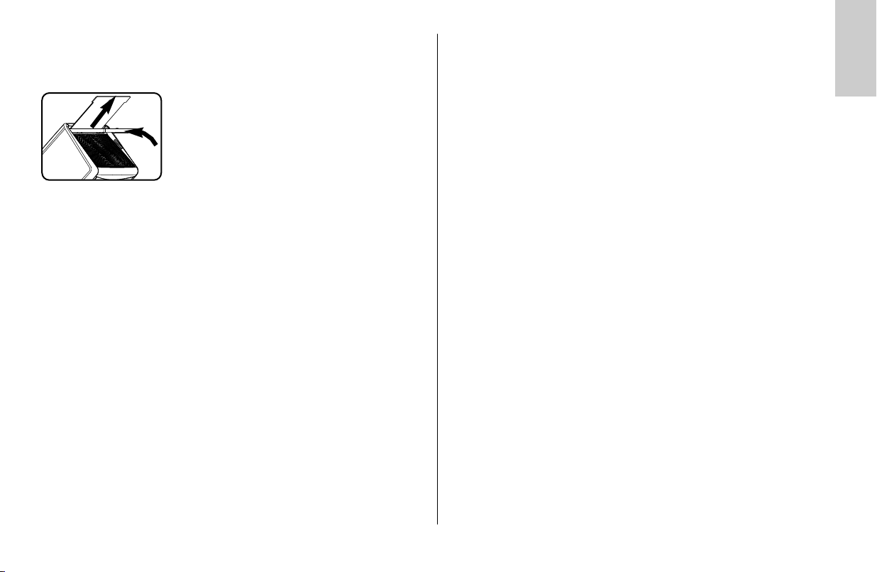
10.2 Indirektes Blitzen mit Reflektorkarte
Durch indirektes Blitzen mit der integrierten Reflektorkarte können bei
Personen Spitzlichter in den Augen erzeugt werden:
• Den Reflektorkopf um 90° nach oben schwenken.
• Die Reflektorkarte zusammen mit der
Weitwinkelstreuscheibe oben aus dem
Reflektorkopf nach vorne heraus ziehen.
• Die Reflektorkarte halten und die
Weitwinkelstreuscheibe in den Reflektorkopf
zurück schieben.
10.3 Nahaufnahmen / Makroaufnahmen
Im Nahbereich und bei Makroaufnahmen kann es durch den Parallaxefehler
zwischen Blitzgerät und Objektiv am unteren Bildrand zu Abschattungen kommen. Um dies auszugleichen, kann der Hauptreflektor um einen Winkel von
-7° nach unten geschwenkt werden.
Dazu den Entriegelungsknopf drücken und den Hauptreflektor nach unten
schwenken.
Bei Aufnahmen im Nahbereich ist zu beachten, dass bestimmte
Mindestbeleuchtungsabstände eingehalten werden müssen, um eine Überbelichtung zu vermeiden.
Der Mindestbeleuchtungsabstand beträgt ca. 10% der im Display ange-
☞
zeigten Reichweite. Wenn der Reflektorkopf nach unten geschwenkt ist,
blinkt als Hinweis dafür die Reichweitenanzeige. Achten Sie darauf, dass
bei Nahaufnahmen das Blitzlicht nicht durch das Objektiv abgeschattet
wird!
11 Blitzsynchronisation
11.1 Automatische Blitzsynchronzeitsteuerung
Je nach Kameratyp und Kamerabetriebsart wird bei Erreichen der
Blitzbereitschaft die Verschlusszeit auf die Blitzsynchronzeit umgeschaltet (siehe
Kamerabedienungsanleitung).
Kürzere Verschlusszeiten als die Blitzsynchronzeit können nicht eingestellt werden, bzw. werden auf die Blitzsynchronzeit umgeschaltet. Verschiedene
Kameras verfügen über einen Synchronzeitbereich, z.B. 1/60s bis 1/250s (siehe Kamerabedienungsanleitung).
Welche Synchronzeit die Kamera einsteuert, ist dann von der
Kamerabetriebsart, vom Umgebungslicht und der verwendeten
Objektivbrennweite abhängig.
Längere Verschlusszeiten als die Blitzsynchronzeit können je nach
Kamerabetriebsart und gewählter Blitzsynchronisation (siehe 11.3 und 11.4)
verwendet werden.
☞
Ķ
Bei Kameras mit Zentralverschluss und bei Kurzzeitsynchronisation (siehe
11.5) erfolgt keine automatische Blitzsynchronzeitsteuerung. Dadurch
kann mit allen Verschlusszeiten geblitzt werden. Sollten Sie die volle
Lichtleistung des Blitzgerätes benötigen, so sollten Sie keine kürzeren
Verschlusszeiten als 1/125s wählen.
19
Page 20

11.2 Normalsynchronisation
Ķ
Bei der Normalsynchronisation wird das Blitzgerät zum Beginn der
Verschlusszeit ausgelöst (Synchronisation auf den 1.Verschlussvorhang). Die
Normalsynchronisation ist der Standardbetrieb und wird von allen Kameras
ausgeführt. Sie ist für die meisten Blitzaufnahmen
geeignet. Die Kamera wird abhängig von ihrer
Betriebsart auf die Blitzsynchronzeit umgeschaltet.
Üblich sind Zeiten zwischen 1/30s und 1/125s (siehe
Kamerabedienungsanleitung). Am Blitzgerät erfolgt
keine Anzeige für diesen Betrieb.
11.3 Synchronisation auf den 2.Verschlussvorhang (REAR)
Einige Kameras bieten die Möglichkeit zur Synchronisation auf den
2.Verschlussvorhang (REAR). Dabei wird das Blitzgerät erst zum Ende der
Verschlusszeit ausgelöst. Dies ist vor allem bei Belichtungen mit langen
Verschlusszeiten (> 1/30s) und bewegten Motiven mit eigener Lichtquelle von
Vorteil, weil bewegte Lichtquellen dann einen Lichtschweif hinter sich herziehen,
anstatt ihn - wie beim Synchronisieren auf den
1.Verschlussvorhang - vor sich aufzubauen. Dadurch
wird bei bewegten Lichtquellen eine „natürlichere“
Wiedergabe der Aufnahmesituation bewirkt! In
Abhängigkeit der Betriebsart steuert die Kamera längere Verschlusszeiten als die Blitzsynchronzeit ein.
Bei einigen Kameras ist in bestimmten Betriebsarten (z.B. bestimmte Vari- bzw.
Motiv-Programme oder bei Vorblitzfunktion gegen „Rote-Augen-Effekt“ der REARBetrieb nicht möglich. Der REAR-Betrieb lässt sich dann nicht anwählen, bzw. wird
automatisch gelöscht oder nicht ausgeführt (siehe Kamerabedienungsanleitung).
Der REAR-Betrieb wird an der Kamera eingestellt (siehe Kamerabedienungsanleitung). Am Blitzgerät erfolgt keine Anzeige für den REAR-Betrieb
11.4 Langzeitsynchronisation (SLOW)
Mit der Langzeitbelichtung SLOW wird der Bildhintergrund bei geringer
Umgebungshelligkeit stärker zur Geltung gebracht. Erreicht wird dies durch
Kameraverschlusszeiten, die dem Umgebungslicht angepasst sind.
Dabei werden von der Kamera automatisch Verschlusszeiten, die länger als die
Blitzsynchronzeit sind (z.B. Verschlusszeiten bis zu 30s), eingesteuert.
Bei einigen Kameratypen wird die Langzeitsynchronisation in bestimmten
Kameraprogrammen (z.B. Nachtaufnahme-Programm usw.) automatisch aktiviert bzw. kann an der Kamera eingestellt werden (siehe
Kamerabedienungsanleitung). Am Blitzgerät erfolgt keine Einstellung bzw.
Anzeige für diesen Betrieb.
Die Einstellung für die Langzeitsynchronisation SLOW erfolgt an der
☞
Kamera (siehe Kamerabedienungsanleitung)! Verwenden Sie bei langen
Verschlusszeiten ein Stativ um verwackelte Aufnahmen zu vermeiden!
11.5 Vorblitzfunktion gegen den „Rote-Augen-Effekt“
Verschiedene Kameras verfügen über die Möglichkeit zur Aktivierung einer
Vorblitzfunktion gegen den „Rote-Augen-Effekt“ (Red-Eye-Reduction).
Diese Funktion unterstützt nur das in der Kamera eingebaute Blitzgerät.
Externe Blitzgeräte werden von dieser Funktion grundsätzlich nicht unterstützt.
20
Page 21

12 Automatischer AF-Messblitz
Sobald die Umlichtverhältnisse für eine automatische Fokussierung nicht mehr
ausreichen, wird von der Kamera automatisch der AF-Messblitz im Blitzgerät
aktiviert. Dabei wird ein Streifenmuster auf das Motiv projiziert, auf das die
Kamera scharf stellen kann. Die Reichweite beträgt ca. 6m ... 9m (bei
Standardobjektiv 1,7/50 mm).
Wegen der Parallaxe zwischen Objektiv und AF–Messblitz im Blitzgerät beträgt
die Naheinstellgrenze mit AF-Messblitz
ca. 0,7m bis1m.
Damit der AF-Messblitz von der Kamera aktiviert werden kann, muss
☞
an der Kamera die Autofokus-Betriebsart „Single-AF (S)“ eingestellt sein
und das Blitzgerät muss Blitzbereitschaft anzeigen.
Einige Kameratypen unterstützen nur den kamerainternen AF-Messblitz.
Der AF-Messblitz des Blitzgerätes wird dann nicht aktiviert (z.B. bei
Kompaktkameras; siehe Kamerabedienungsanleitung)!
Zoomobjektive mit geringer Anfangsblendenöffnung schränken die Reichweite
des AF-Messblitzes zum Teil erheblich ein!
Verschiedene Kameratypen unterstützen nur mit dem zentralen AF-Sensor der
Kamera den AF-Messblitz im Blitzgerät.
Wird ein dezentraler AF-Sensor gewählt, so wird der AF-Messblitz im Blitzgerät
nicht aktiviert!
13 Zündungssteuerung (Auto-Flash)
Ist das vorhandene Umgebungslicht für eine Belichtung im normalen Modus
ausreichend, so verhindert die Kamera die Blitzauslösung.
Die Belichtung erfolgt dann mit der im Display bzw. Sucher der Kamera angezeigten Verschlusszeit. Die Aktivierung der Zündungssteuerung wird durch das
Verlöschen der Blitzbereitschaftsanzeige im Kamerasucher signalisiert.
Beim Betätigen des Kameraauslösers wird kein Blitzlicht ausgelöst.
Die Zündungssteuerung arbeitet bei verschieden Kameras nur in der Betriebsart
Programm „P“ und Blendenautomatik „S“ (siehe Kamerabedienungsanleitung).
Die Zündungssteuerung kann bei verschiedenen Kameras deaktiviert werden:
• Drücken Sie dazu an der Kamera die Taste für die Blitzsteuerung (siehe
Kamerabedienungsanleitung) und halten Sie diese bei der Aufnahme
gedrückt.
Beim Antippen des Kameraauslösers erscheint im Kamerasucher nun wieder die
Blitzbereitschaftsanzeige. Die Kameraelektronik wählt eine geeignete
Zeit–Blenden-Kombination. Bei der Aufnahme wird ein Blitz ausgelöst.
Ķ
21
Page 22
Ķ
14 Wartung und Pflege
Entfernen Sie Schmutz und Staub mit einem weichen, trockenen Tuch.
Verwenden Sie keine Reinigungsmittel - die Kunststoffteile könnten beschädigt
werden.
14.1 Firmware-Update
Die Firmware-Version des Blitzgerätes wird im Display angezeigt, wenn beim
Einschalten gleichzeitig die Taste „Mode“ gedrückt wird.
Die Firmware des Blitzgerätes kann über die USB Firmwareupdate-Buchse
aktualisiert und im technischen Rahmen an die Funktionen zukünftiger Kameras
angepasst werden.
Nähere Informationen finden Sie im Internet auf der Metz-Homepage:
☞
www.metz.de
14.2 Reset
Das Blitzgerät kann auf die Werkseinstellung bei Auslieferung zurück gestellt
werden.
14.3 Formieren des Blitzkondensators
Der im Blitzgerät eingebaute Blitzkondensator erfährt eine physikalische
Veränderung, wenn das Gerät längere Zeit nicht eingeschaltet wird. Aus diesem
Grund ist es notwendig, das Gerät im vierteljährlichen Abstand für ca. 10 Min.
einzuschalten. Die Stromquellen müssen dabei so viel Energie liefern, dass die
Blitzbereitschaft längstens 1 Min. nach dem Einschalten aufleuchtet.
rES
5 Sek.
Nach ca. 5 Sekunden wird im Display kurzzeitig „rES“ (= Reset) angezeigt und
das Blitzgerät wird in den Auslieferungszustand zurück gesetzt.
☞
22
☛
Firmware-Updates des Blitzgerätes sind dabei nicht betroffen!
rES
• Dazu die Taste „Mode“ drücken und für
ca. 5 Sekunden gedrückt halten.
Page 23

15 Hilfe bei Störungen
Sollte es einmal vorkommen dass z.B. im Display des Blitzgerätes unsin-
☞
nige Anzeigen erscheinen oder das Blitzgerät funktioniert nicht so wie es
soll, so schalten Sie das Blitzgerät für ca. 10 Sekunden mit dem
Hauptschalter aus. Überprüfen Sie die korrekte Montage des
Blitzgerätefußes im Zubehörschuh der Kamera und die
Kameraeinstellungen.
Tauschen Sie die Batterien bzw. Akkus gegen neue Batterien bzw. frisch geladene Akkus aus!
Das Blitzgerät sollte nach dem Einschalten wieder „normal“ funktionieren. Ist
dies nicht der Fall, so wenden Sie sich bitte an Ihren Fachhändler.
Nachfolgend sind einige Probleme aufgeführt, die in der Blitz-Praxis auftreten
können. Unter den jeweiligen Punkten sind mögliche Ursachen bzw. Abhilfen für
diese Probleme aufgeführt.
Im Display erfolgt keine Reichweitenanzeige.
• Es hat kein Datenaustausch zwischen Blitzgerät und Kamera stattgefunden.
Kameraauslöser antippen.
• Der Hauptreflektor befindet sich nicht in der Normalposition.
Der AF-Messblitz des Blitzgerätes wird nicht aktiviert.
• Das Blitzgerät ist nicht blitzbereit.
• Die Kamera arbeitet nicht in der Betriebsart Single-AF (S-AF).
• Die Kamera unterstützt nur den eigenen internen AF-Meßblitz.
• Verschiedene Kameratypen unterstützen nur mit dem zentralen AF-Sensor der
Kamera den AF-Messblitz im Blitzgerät. Wird ein dezentraler AF-Sensor
gewählt, so wird der AF-Messblitz im Blitzgerät nicht aktiviert!
Zentralen AF–Sensor aktivieren!
Die Zoom-Position des Hauptreflektors wird nicht automatisch der aktuellen
Zoom-Position des Objektivs angepasst.
• Die Kamera überträgt keine Daten an das Blitzgerät
• Es findet kein Datenaustausch zwischen Blitzgerät und Kamera statt.
Kameraauslöser antippen!
• Die Kamera ist mit einem Objektiv ohne CPU ausgerüstet.
• Das Blitzgerät arbeitet im manuellen Zoombetrieb „MZoom“.
Auf Auto-Zoom umschalten (siehe 9.1).
• Der Hauptreflektor ist aus seiner verriegelten Normalposition geschwenkt.
• Die Weitwinkelstreuscheibe ist vor dem Hauptreflektor geklappt.
• Vor dem Hauptreflektor ist ein Mecabounce montiert.
Die Blendeneinstellung des Blitzgerätes wird nicht automatisch der des
Objektivs angepasst.
• Die Kamera überträgt keine Daten an das Blitzgerät.
• Es findet kein Datenaustausch zwischen Blitzgerät und Kamera statt.
Kameraauslöser antippen!
• Die Kamera ist mit einem Objektiv ohne CPU ausgerüstet.
Im Display blinkt die Anzeige für die Zoom-Position des Hauptreflektors
• Warnhinweis wegen Abschattung am Bildrand: Die an der Kamera eingestellte Brennweite des Objektivs (umgerechnet auf das 35 mm - Kleinbild-Format
24x36) ist kleiner als die eingestellte Zoom-Position des Hauptreflektors.
Ķ
23
Page 24

Es findet keine automatische Umschaltung auf die Blitzsynchronzeit statt
Ķ
• Die Kamera hat einen Zentralverschluss (die meisten Kompaktkameras).
Die Umschaltung auf Synchronzeit ist daher nicht erforderlich.
• Das Blitzgerät arbeitet mit Kurzzeitsynchronisation HSS. Dabei findet keine
Umschaltung auf die Synchronzeit statt.
• Die Kamera arbeitet mit Verschlusszeiten, die länger als die Blitzsynchronzeit
ist. In Abhängigkeit von der Kamerabetriebsart wird dabei nicht auf die
Blitzsynchronzeit umgeschaltet (siehe Kamerabedienungsanleitung).
Die Aufnahmen sind an der Bildunterseite abgeschattet.
• Durch die Parallaxe zwischen Objektiv und Blitzgerät kann die Aufnahme im
Nahbereich in Abhängigkeit von der Brennweite an der Bildunterseite nicht
vollständig ausgeleuchtet werden. Neigen Sie den Reflektorkopf nach unten
bzw. schwenken Sie die Weitwinkelstreuscheibe vor den Hauptreflektor.
Die Aufnahmen sind zu dunkel.
• Das Motiv liegt außerhalb der Reichweite des Blitzgerätes. Beachten Sie: Beim
indirekten Blitzen verringert sich die Reichweite des Blitzgerätes.
• Das Motiv enthält sehr helle oder reflektierende Bildpartien. Dadurch wird das
Messsystem der Kamera bzw. des Blitzgerätes getäuscht.
Stellen Sie eine positive manuelle Blitzbelichtungskorrektur ein, z.B. +1 EV.
Die Aufnahmen sind zu hell.
• Im Nahbereich kann es zu Überbelichtungen (Aufnahmen sind zu hell) kommen, wenn die kürzeste Leuchtzeit des Blitzgerätes unterschritten wird. Der
Mindestabstand zu Motiv sollte mindestens 10% der im Display angezeigten
Reichweite betragen.
24
Page 25

16 Technische Daten
Maximale Leitzahl bei ISO 100; Zoom 105 mm:
Im Meter-System: 50 Im Feet-System:165
Blitzbetriebsar
TTL (ohne Vorblitz), Vorblitz-TTL, ADI-Messung, Manuell M,
Kurzzeitsynchronisation HSS, Remote-Slave.
Manuelle Teillichtleistungen:
P1/1 bis P1/128
P1/1 bis P1/32 bei Kurzzeitsynchronisation HSS
Blitzleuchtzeiten siehe T
Farbtemperatur:
Ca. 5600 K
Lichtempfindlichkeit:
ISO 6 bis ISO 6400
Synchronisation:
Niederspannungs – IGBT – Zündung
Blitzanzahlen:
Mit Hochleistungs-Alkali-Mangan-Batterien ca. 210
Mit NiMH-Akkus (2100 mAh) ca. 330
Mit Lithium-Batterien ca. 460.
Blitzfolgezeit
ten:
abelle 2 (Seite 152):
(bei jeweils voller Lichtleistung)
bei jeweils voller Lichtleistung: ca. 3,5 s.
Ausleuchtung des Motorzoom-Hauptreflektors:
Ab 24 mm (Kleinbild-Format 24 x 36).
Ab 12 mm mit integrierter Weitwinkelstreuscheibe (Kleinbild-Format 24 x 36).
Schwenkbereiche und Raststellungen des Reflektorkopfes:
Vertikal: -7° 45° 60° 75° 90°
Horizontal gegen den Uhrzeigersinn:
30° 60° 90° 120° 150° 180°
Horizontal im Uhrzeigersinn:
30° 60° 90° 120°
Abmaße in mm (B x H x T):
Ca. 71 x 137 x 99
Gewicht :
Blitzgerät mit Stromquellen: ca. 452 g
Auslieferungsumfang:
Blitzgerät mit integrierter Weitwinkelstreuscheibe und Reflektorkarte,
Bedienungsanleitung.
Ķ
25
Page 26
Ķ
17 Sonderzubehör
Für Fehlfunktionen und Schäden am Blitzgerät, verursacht durch die
☞
Verwendung von Zubehör anderer Hersteller, wird keine Gewährleistung
übernommen!
• Mecabounce 58-90
(Bestellnr. 000058902)
Mit diesem Diffusor erreichen Sie auf einfachste Weise eine weiche Ausleuchtung. Die Wirkung ist großartig, weil die Bilder einen softartigen Effekt
erhalten. Die Gesichtsfarbe von Personen wird natürlicher wiedergegeben.
Die Grenzreichweiten verringern sich entsprechend dem Lichtverlust circa auf
die Hälfte.
• Reflexschirm 58-23
(Bestellnr. 000058235)
Mildert durch sein weiches gerichtetes Licht harte Schlagschatten.
• Blitzgeräte-Standfuß S60
(Bestellnr. 000000607)
Blitzgeräte-Standfuß für den Slave-Betrieb.
Batterie-Entsorgung
Batterien/Akkus gehören nicht in den Hausmüll! Bitte bedienen Sie sich bei der
Rückgabe verbrauchter Batterien/Akkus eines vorhandenen Rücknahmesystems.
Bitte geben Sie nur entladene Batterien/Akkus ab. Batterien sind in der Regel
dann entladen, wenn das damit betriebene Gerät
- abschaltet und signalisiert „Batterien leer“
- nach längerem Gebrauch der Batterien nicht mehr einwandfrei funktioniert.
Zur Kurzschlusssicherheit sollten die Batteriepole mit einem Klebestreifen über-
deckt werden.
Deutschland: Als Verbraucher sind Sie gesetzlich verpflichtet, gebrauchte
Batterien zurückzugeben. Sie können Ihre alten Batterien überall dort unentgeltlich abgeben, wo die Batterien gekauft wurden. Ebenso bei den öffentlichen
Sammelstellen in Ihrer Stadt oder Gemeinde.
Diese Zeichen finden Sie auf schadstoffhaltigen Batterien:
Pb = Batterie enthält Blei
Cd = Batterie enthält Cadmium
Hg = Batterie enthält Quecksilber
Li = Batterie enthält Lithium
26
Technische Änderungen und Irrtümer vorbehalten !
Page 27

Garantiebestimmungen
Bundesrepublik Deutschland
1. Die Garantiebestimmungen gelten ausschließlich für Käufe in der
Bundesrepublik Deutschland.
2. Im Ausland gelten die Gewährleistungsregelungen des jeweiligen Landes
bzw. die Garantieregelungen des Verkäufers.
3. Die nachfolgenden Bestimmungen haben nur für den privaten Gebrauch
Gültigkeit.
4. Die Garantiezeit - 24 Monate - beginnt mit dem Abschluss des Kaufvertrages
bzw. mit dem Tag der Auslieferung des Gerätes an den Käufer
(Endverbraucher).
5. Garantieansprüche können nur unter Nachweis des Kaufdatums durch
Vorlage des vom Verkäufer maschinell erstellten Original-Kaufbeleges geltend gemacht werden.
6. Beanstandete Geräte bitten wir zusammen mit dem Kaufbeleg entweder über
den Fachhändler oder direkt an die Firma Metz-Werke GmbH & Co KG Zentralkundendienst - Ohmstrasse 55, 90513 Zirndorf, transportsicher verpackt unter genauer Schilderung der Beanstandung einzusenden. Sie können
unter den gleichen Bedingungen auch an die autorisierten
Kundendienststellen der Firma Metz-Werke GmbH & Co KG eingesandt werden. Hin- und Rücksendung erfolgen auf Gefahr des Käufers.
7.
Die Garantie besteht darin, dass Geräte, die infolge eines anerkannten
Fabrikations- oder Materialfehlers defekt geworden sind, kostenlos repariert
oder, soweit eine Reparatur unverhältnismäßig ist, ausgetauscht werden.
Eine weitergehende Haftung, insbesondere für Schäden, die nicht am Gerät
selbst entstanden sind, ist ausgeschlossen. Dies gilt nicht, soweit im Falle des
Vorsatzes oder der groben Fahrlässigkeit zwingend gehaftet wird.
Garantieleistungen bewirken weder eine Verlängerung der Garantiezeit,
noch wird für die ersetzten oder nachgebesserten Teile eine neue
Garantiezeit begründet.
8. Unsachgemäße Behandlung und Eingriffe durch den Käufer oder Dritte
9. Durch diese Garantiebestimmungen werden die Gewährleistungsansprüche
schließen die Garantieverpflichtungen sowie alle weiteren Ansprüche aus.
Ausgenommen von der Garantie sind ferner Schäden oder Fehler, die durch
Nichtbeachtung der Gebrauchsanleitung, mechanische Beschädigung, ausgelaufene Batterien oder durch höhere Gewalt, Wasser, Blitz etc. entstanden
sind.
Ferner sind Verschleiß, Verbrauch sowie übermäßige Nutzung von der
Garantie ausgenommen. Hiervon sind vor allem folgende Teile betroffen:
Blitzröhre, fest eingebaute Akkus, Kontakte, Verbindungskabel.
des Käufers gegenüber dem Verkäufer nicht berührt.
Metz-Werke GmbH & Co KG
27
Page 28

1 Consignes de sécurité . . . . . . . . . . . . . . . . . . . . . . . . . . . . . . . . . . . . . . 29
2 Fonctions flash dédiées . . . . . . . . . . . . . . . . . . . . . . . . . . . . . . . . . . . . . 30
3 Préparation du flash . . . . . . . . . . . . . . . . . . . . . . . . . . . . . . . . . . . . . . . 30
3.1 Montage du flash . . . . . . . . . . . . . . . . . . . . . . . . . . . . . . . . . . . . . . . . 30
3.2 Alimentation . . . . . . . . . . . . . . . . . . . . . . . . . . . . . . . . . . . . . . . . . . . 30
3.3 Mise en marche et coupure du flash. . . . . . . . . . . . . . . . . . . . . . . . . . . 31
ĸ
3.4 Coupure automatique du flash / Auto - OFF. . . . . . . . . . . . . . . . . . . . . 31
4 DEL de signalisation sur le flash. . . . . . . . . . . . . . . . . . . . . . . . . . . . . . . 32
4.1 Affichage de disponibilité du flash . . . . . . . . . . . . . . . . . . . . . . . . . . . . 32
4.2 Témoin de bonne exposition avec flash . . . . . . . . . . . . . . . . . . . . . . . . 32
5 Indications sur l’écran . . . . . . . . . . . . . . . . . . . . . . . . . . . . . . . . . . . . . . 32
5.1 Affichage du mode flash . . . . . . . . . . . . . . . . . . . . . . . . . . . . . . . . . . . 32
5.2 Affichage de la portée . . . . . . . . . . . . . . . . . . . . . . . . . . . . . . . . . . . . 33
6 Signalisations dans le viseur . . . . . . . . . . . . . . . . . . . . . . . . . . . . . . . . . 34
7 Modes de fonctionnement du flash (menu «Mode» ) . . . . . . . . . . . . . . . . 34
7.1 Modes de fonctionnement TTL . . . . . . . . . . . . . . . . . . . . . . . . . . . . . . . 34
7.2 Mode flash manuel. . . . . . . . . . . . . . . . . . . . . . . . . . . . . . . . . . . . . . . 36
7.3 Synchronisation automatique haute vitesse (HSS) . . . . . . . . . . . . . . . . . 36
8 Correction manuelle d’exposition au flash . . . . . . . . . . . . . . . . . . . . . . . 37
9 Fonctions spéciales (menu «Select» ) . . . . . . . . . . . . . . . . . . . . . . . . . . . 37
9.1 Asservissement de la tête zoom motorisée («Zoom») . . . . . . . . . . . . . . . 37
9.2 Mode multi-flash sans fil (mode Remote). . . . . . . . . . . . . . . . . . . . . . . . 39
9.2.1 Mode flash remote slave ( ). . . . . . . . . . . . . . . . . . . . . . . . . . . . . 39
9.2.2 Mode flash SERVO . . . . . . . . . . . . . . . . . . . . . . . . . . . . . . . . . . . . . 41
9.3 Coupure automatique du flash . . . . . . . . . . . . . . . . . . . . . . . . . . . . 42
SL
9.4 Lumière pilote («ML» - Modelling Light) . . . . . . . . . . . . . . . . . . . . . . . . 42
9.5 Mode zoom étendu («Ex») . . . . . . . . . . . . . . . . . . . . . . . . . . . . . . . . . 43
9.6 Commutation mètres - pieds («m» / «ft» ). . . . . . . . . . . . . . . . . . . . . . . 43
9.7 Adaptation du format de la prise de vue (S.Zoom) . . . . . . . . . . . . . . . . 44
10 Techniques de photographie au flash . . . . . . . . . . . . . . . . . . . . . . . . . . 44
10.1 Éclairage indirect au flash. . . . . . . . . . . . . . . . . . . . . . . . . . . . . . . . . 44
10.2 Éclairage indirect au flash avec carte-réflecteur . . . . . . . . . . . . . . . . . 45
10.3 Photographie rapprochée / macrophotographie. . . . . . . . . . . . . . . . . 45
11 Synchronisation du flash . . . . . . . . . . . . . . . . . . . . . . . . . . . . . . . . . . . 45
11.1 Commutation automatique sur la vitesse de synchro-flash . . . . . . . . . . 45
11.2 Synchronisation normale. . . . . . . . . . . . . . . . . . . . . . . . . . . . . . . . . . 46
11.3 Synchronisation sur le 2e rideau (REAR). . . . . . . . . . . . . . . . . . . . . . . 46
11.4 Synchronisation en vitesse lente (SLOW). . . . . . . . . . . . . . . . . . . . . . . 46
11.5 Fonction de pré-éclairs réducteurs d’yeux rouges . . . . . . . . . . . . . . . . 46
12 Illuminateur AF automatique . . . . . . . . . . . . . . . . . . . . . . . . . . . . . . . . 47
13 Commande automatique du flash (flash automatique) . . . . . . . . . . . . . 47
14 Maintenance et entretien. . . . . . . . . . . . . . . . . . . . . . . . . . . . . . . . . . . 47
14.1 Mise à jour du micrologiciel . . . . . . . . . . . . . . . . . . . . . . . . . . . . . . . 47
14.2 Réinitialisation . . . . . . . . . . . . . . . . . . . . . . . . . . . . . . . . . . . . . . . . . 48
14.3 Formation du condensateur de flash. . . . . . . . . . . . . . . . . . . . . . . . . . 48
15 Remède en cas de mauvais fonctionnement . . . . . . . . . . . . . . . . . . . . . 48
16 Caractéristiques techniques . . . . . . . . . . . . . . . . . . . . . . . . . . . . . . . . . 50
17 Accessoires en option . . . . . . . . . . . . . . . . . . . . . . . . . . . . . . . . . . . . . 51
Tableau 1 - 4: . . . . . . . . . . . . . . . . . . . . . . . . . . . . . . . . . . . . . . . . 151-153
28
Page 29

Avant-propos
Nous vous remercions d’avoir choisi un produit Metz et sommes heureux de
vous saluer au sein de la grande famille de nos clients.
Nous savons que vous brûlez d’envie d’essayer votre flash. Prenez tout de
même le temps de lire le mode d’emploi. C’est la seule manière de découvrir les
potentialités de votre flash et d’apprendre à les utiliser.
Ce flash convient aux
• Appareil photo reflex numérique Sony avec fonction TTL, pré-éclair TTL et
mesure ADI.
Ce flash n’est pas compatible avec les appareils d’autres fabricants !
☞
Veuillez également déplier le rabat en dernière page pour consulter les
illustrations.
1 Consignes de sécurité
• Le flash est conçu et agréé pour l’emploi exclusif en photographie.
• Ne déclenchez en aucun cas un éclair à proximité de gaz ou de liquides
inflammables (essence, diluants, etc.) ! RISQUE D’EXPLOSION !
• Ne photographiez jamais au flash le conducteur d’un bus, d’un train, d’une
voiture, d’une moto ni un cycliste, car sous le coup de l’éblouissement il
risque de provoquer un accident !
• Ne déclenchez jamais le flash à proximité des yeux ! L’amorçage d’un
éclair directement devant les yeux de personnes ou d’animaux peut
entraîner une lésion de la rétine et occasionner de graves troubles visuels
pouvant aller jusqu’à l’aveuglement.
• Utilisez exclusivement les sources d’énergie autorisées mentionnées dans le
mode d’emploi.
• N’exposez pas les piles ou accus à une trop grande chaleur, par ex. au
soleil, aux flammes ou autre.
• Ne jetez pas au feu les piles ni les accus usés !
• Sortez immédiatement les piles usées du flash ! En effet, les piles usées
peuvent „couler“ et provoquer une dégradation du flash.
• Ne rechargez pas les piles sèches !
• Maintenez votre flash et le chargeur à l’abri de l’eau tombant en gouttes et
des projections d’eau !
• Ne soumettez pas le flash à une trop grande chaleur ni à une trop forte humidité de l’air ! Ne conservez pas le flash dans la boîte à gants de votre voiture !
• Au moment de déclencher un éclair, il ne doit pas y avoir de matière opaque directement devant ni sur la glace du réflecteur. La glace du réflecteur
ne doit pas non plus être souillée. En cas de non-respect de cette consigne
de sécurité, l’énergie de l’éclair peut provoquer des brûlures sur la matière
opaque ou sur la glace du réflecteur.
• Après une séquence d’éclairs, la glace du réflecteur est très chaude.
Ne la touchez pas, risque de brûlure !
• Ne démontez pas le flash ! DANGER HAUTE TENSION !
Le flash ne renferme pas de pièces susceptibles de pouvoir être réparées
par un non-spécialiste.
• Si vous effectuez des séries de photos au flash à pleine puissance en bénéficiant de temps de recyclage courts, veillez à respecter une pause d’au
moins 10 minutes après chaque série de 15 flashs!
• Si vous effectuez des séries de photos au flash à pleine puissance en bénéficiant de temps de recyclage courts avec une position zoom à 35 mm et en
dessous, le diffuseur grand-angle risque de beaucoup chauffer en raison de
la forte énergie de l'éclair.
• Le flash ne peut être utilisé conjointement avec le flash intégré de l’appareil
photo que si celui-ci peut être complètement déployé !
• Un changement rapide de température peut entraîner la formation de buée.
Laissez le temps à l’appareil pour s’acclimater !
• N’utilisez pas des piles ou accus défectueux !
ĸ
29
Page 30

2 Fonctions de flash système
Les fonctions de flash système sont des fonctions de flash conçues spécialement
pour le système d'appareil photo. Différentes fonctions de flash sont prises en
charge selon le modèle d'appareil.
• Témoin de disponibilité du flash dans le viseur de l'appareil photo
• Vitesse de synchro-flash automatique
ĸ
• Contrôle TTL du flash (TTL standard sans pré-éclair de mesure)
• Pré-éclair TTL et mesure ADI
• Dosage automatique flash/ambiance
• Correction manuelle de l'exposition au flash
• Synchronisation sur le 1er ou 2ème rideau (REAR)
• Synchronisation haute vitesse (HSS) automatique en mode TTL et M
• Contrôle automatique de la tête zoom motorisée
• Mode zoom étendu
• Commande de l'éclair d'assistance AF
• Affichage automatique de la portée de l'éclair
• Inhibition du flash (AUTO-FLASH)
• Mode remote sans fil
• Fonction de réveil du flash
• Mise à jour du micrologiciel
Dans le cadre du présent mode d’emploi, il n’est pas possible d’aborder
☞
en détail tous les types d’appareils photo et leurs fonctions flash correspondantes. Nous vous renvoyons à ce sujet à la description de l’emploi
du flash figurant dans le mode d’emploi de l’appareil photo où sont indiquées les fonctions de flash supportées par votre appareil photo ou à
régler directement sur l’appareil photo !
3 Préparation du flash
3.1 Montage du flash
Fixation du flash sur l’appareil
Éteindre l’appareil photo et le flash avant le montage ou le démontage
☞
du flash !
• Tournez l’écrou moleté jusqu’en butée contre le flash.
•
Engagez le sabot du flash dans la griffe porte-accessoires de l’appareil photo
• Tournez l’écrou moleté jusqu’en butée contre le boîtier de l’appareil photo
pour bloquer le flash.
Retirer le flash de l’appareil photo
Éteindre l’appareil photo et le flash avant le montage ou le démontage
☞
du flash !
• Tournez l’écrou moleté jusqu’en butée contre le flash.
• Dégagez le flash de la griffe porte-accessoires de l’appareil photo.
3.2 Alimentation
Choix des piles ou accus
Le flash peut fonctionner sur :
• 4 accus NiCd de 1,2 V, type CEI KR6 (AA / Mignon), ils procurent des temps
de recyclage très courts et sont économiques à l’usage car rechargeables.
• 4 accus au nickel-hydrure métallique de 1,2 V, type CEI HR6 (AA / Mignon),
capacité nettement supérieure à celle des accus NiCd et moins nuisibles à
l’environnement car sans cadmium.
• 4 piles sèches alcalines au manganèse de 1,5 V, type CEI LR6 (AA /
Mignon), source de courant sans entretien pour exigences de performances
moyennes.
• 4 piles au lithium de 1,5 V, type CEI FR6 (AA / Mignon), source de courant
sans entretien à haute performance et avec une perte de capacité minime.
.
30
Page 31

Si le flash reste inutilisé pendant une longue période, retirez les piles ou
☞
accus de l’appareil.
Remplacement des piles
Les accus ou les piles sont vides ou usé(e)s lorsque le temps de recyclage (délai
entre le déclenchement d’un éclair à pleine puissance, par ex. sur M, et l’instant
d’allumage du témoin de disponibilité dépasse les 60 secondes.
• Éteignez le flash en appuyant sur l’interrupteur principal .
• Repoussez le couvercle du compartiment des piles
vers l’avant et ouvrez-le.
• Introduisez les piles ou les accus dans le sens de la
longueur en vous conformant aux symboles de piles.
Introduisez d’abord les piles dirigées vers l’écran,
puis les autres. Refermez le couvercle du compartiment des piles .
À la mise en place des piles ou accus, respectez
☞
la polarité (voir les symboles de piles figurant
dans le compartiment des piles). Une inversion
de polarité peut conduire à la destruction de
l’appareil ! Remplacez toujours les piles et accus
par jeu complet de piles/accus identiques d’un
même fabricant et de même capacité ! Pensez à
la protection de l’environnement ! Ne jetez pas
les piles ou accus à la poubelle, mais apportezles à un point de collecte !
3.3 Mise en marche et coupure du flash
Mettez le flash en marche en appuyant sur l’interrupteur principal . Le flash est sous tension lorsque l’interrupteur principal est sur «ON».
Pour éteindre le flash, repoussez l’interrupteur principal vers la gauche.
☞
3.4 Coupure automatique du flash / Auto - OFF
En usine, le flash est réglé pour se mettre en veille (Auto-OFF) 10 minutes environ après
• la mise en marche,
• après activation d’une touche,
• le déclenchement d’un éclair,
• l’enfoncement à mi-course du déclencheur de l’appareil photo,
• l’arrêt du système de mesure d’exposition de l’appareil photo...
...pour éviter une consommation inutile d’énergie et ménager ainsi les piles ou
accus. L’activation de la mise hors tension automatique de l’appareil est indiquée sur l’écran. Le témoin de disponibilité et les affichages sur l’écran
ACL du flash s’éteignent.
☞
Les réglages effectués avant l’arrêt automatique sont conservés et sont rétablis
immédiatement à la remise en marche. Le flash est réactivé en appuyant sur une
touche quelconque ou en enfonçant à mi-course le déclencheur de l’appareil
photo (fonction de réveil).
☞
Si nécessaire, le flash peut s’éteindre déjà après 1 minute ou il est possible de
désactiver la fonction d’arrêt automatique (voir 9.3).
Si le flash reste inutilisé pendant une période prolongée, nous recommandons d’éteindre le flash avec l’interrupteur principal et de retirer
les piles ou accus.
En mode esclave, la mise hors tension automatique n’est pas activée.
Si le flash reste inutilisé pendant une période prolongée, il est conseillé de
couper le flash avec l’interrupteur principal
ĸ
31
Page 32

4 DEL de signalisation sur le flash
4.1 Affichage de disponibilité du flash
Lorsque le condensateur du flash est chargé, le témoin
de disponibilité s’allume sur le flash. Il signale
ainsi que la prochaine photo peut être prise avec
ĸ
disponibilité dans le viseur, le flash n’est pas déclenché, ce qui peut conduire
éventuellement à une sous-exposition si l’appareil a déjà été réglé sur la vitesse
de synchro-flash (voir 11.1).
4.2 Témoin de bonne exposition avec flash
✴
✴
avec une plus grande ouverture du diaphragme (plus petit indice d’ouverture
suivant, par exemple f/8 au lieu de f/11) ou en se rapprochant du sujet ou de
la surface réfléchissante (par exemple en éclairage indirect).
Observez l’indication de la portée sur l’écran du flash (voir 5.2).
l’éclairage par le flash. La disponibilité du flash est
aussi transmise à l’appareil photo et est signalée dans
le viseur (voir 6).
Si l’on prend la photo avant l’apparition du témoin de
Le témoin de bonne exposition «o.k.» d s’allume
pendant 3 secondes environ si la prise effectuée avec
le mode flash TTL (TTL, Pré-éclair-TTL, mesure ADI;
voir 7) a été correctement exposée !
Si le témoin de bonne exposition avec flash «o.k.»
ne s’allume pas après la prise de vue, c’est que la
photo a été sous-exposée et il faut refaire la photo
5 Indications sur l’écran
Les appareils photo transmettent les valeurs ISO, la distance focale de l’objectif
(mm) et l’ouverture du diaphragme au flash. Celui-ci adapte alors automatiquement ses réglages nécessaires. A partir des valeurs et de son nombre-guide, il
calcule la portée maximale de l’éclair. Le type de flash, la portée, l’ouverture du
diaphragme et la position zoom du réflecteur principal s’affichent sur l’écran du
flash.
Si le flash est utilisé sans avoir reçu des données de l’appareil photo (par exemple si l’appareil photo est éteint), seuls le mode flash sélectionné, la position du
zoom du réflecteur principal et l’indication «Zoom» s’affichent. Les indications
pour le diaphragme et la portée s’affichent seulement si le flash a reçu les
données nécessaires de l’appareil photo.
Des indications pour le zoom automatique, le diaphragme et la portée
☞
s’affichent uniquement avec des appareils photo qui transmettent des
valeurs du diaphragme et des valeurs ISO au flash!
Éclairage de l’écran
L’écran s’allume pour environ 10 secondes dès que vous appuyez sur une
touche quelconque du flash. L’écran s’éteint lorsqu’un éclair est déclenché avec
l’appareil photo ou avec le bouton du flash
5.1 Affichage du mode flash
L’écran affiche le mode flash choisi. A cet
égard, différents affichages sont possibles
pour le mode flash TTL pris en charge
(p.ex. , HSS) et le mode flash
manuel , HSS (voir 7), selon le modèle
d’appareil photo.
TTLTTL
MM
TTL
TTL
Zoom
m
13
mm
70
32
Page 33

5.2 Affichage de la portée
Lors de l’utilisation d’appareils photo qui transmettent des données concernant
l’ISO, la distance focale de l’objectif et le diaphragme, l’indication de la portée
s’affiche à l’écran. Pour cela, un échange de données doit avoir eu lieu entre
l’appareil photo et le flash, par exemple par l’enfoncement à mi-course du
déclencheur de l’appareil photo. La portée peut s’afficher soit en mètres (m),
soit en pieds (ft - feet) (voir 9.6).
Aucune portée ne s’affiche si aucune donnée n’est transmise par
☞
l’appareil photo.
- lorsque la tête zoom est orientée différemment de sa position normale
(vers le haut ou le côté) ;
- lorsque le flash travaille en mode flash remote (Slave SL).
- L'affichage de la portée clignote lorsque le réflecteur est basculé vers le
bas (voir 10.3).
Affichage de la portée en modes flash TTL
13
m
TTL
Zoom
m
13
70
✴
très faiblement réfléchissants, peuvent influencer la portée du flash.
Le sujet devrait se situer entre environ 40 et 70 % de la portée affichée, pour
laisser au système électronique une latitude suffisante pour doser la lumière. La
distance minimale flash-sujet à respecter pour éviter toute surexposition devrait
être égale à 10 % de la valeur affichée ! L’adaptation à la situation de prise de
vue est possible par exemple en modifiant l’ouverture du diaphragme.
En modes flash TTL (voir 7.1), l’écran affiche
la valeur de la portée maximale de l’éclair.
mm
La valeur affichée se rapporte à la réflectance de 25 % du sujet, ce qui est le cas dans la
plupart des situations de prise de vue. Des
écarts importants du degré de réflectance,
par exemple pour des sujets très fortement ou
Indication de la portée en mode flash manuel M
En mode flash manuel M, l’écran indique la
valeur de la distance à respecter pour une
exposition correcte du sujet au flash.
L’adaptation à la situation de prise de vue est
possible par exemple en modifiant l’ouverture
du diaphragme ou en choisissant une puissance
partielle manuelle (voir 7.2).
Dépassement de la capacité d’affichage
L’écran du flash peut afficher une portée maximale de 199 m ou 199 ft. Pour des valeurs
élevées de sensibilité ISO (par exemple ISO
6400) et de grandes ouvertures du diaphragme,
il peut arriver que la portée maximale affichable
soit dépassée. Ceci est signalé par une flèche ou
un triangle derrière la valeur de la distance
affichée.
6 Signalisations dans le viseur
Selon le modèle d'appareil, différents symboles s’affichent dans le viseur pour
indiquer le statut du flash après la prise de vue. Consultez le mode d'emploi de
votre appareil photo.
Exemples d'affichages dans le viseur:
• Le symbole
• Le symbole éclair s’allume:
m
2,5
199
m
éclair clignote avant la prise de vue:
le condensateur du flash est en cours de charge.
Le flash n'est pas encore prêt à l'utilisation.
le condensateur du flash est chargé.
Le flash est prêt à être utilisé.
2,5
M
199
M
Zoom
m
m
✴
Zoom
mm
35
ĸ
mm
70
✴
33
Page 34

7 Modes de fonctionnement du flash (menu «Mode» )
TTL
TTL
Zoom
m
20
35
ĸ
☛
déclencheur de l’appareil photo. Le réglage du mode flash se fait à
l’aide de la touche «Mode» .
7.1 Modes de fonctionnement TTL
Les modes flash TTL vous permettent de réussir sans peine vos photos au flash.
Dans ces modes, la mesure de l’exposition est effectuée par une cellule intégrée à
l’appareil photo. Cette cellule mesure la lumière réfléchie par le sujet à travers
l’objectif (TTL = «Through The Lens» ). L’appareil photo détermine alors automatiquement la puissance d’éclair nécessaire pour une exposition correcte de la prise
de vue. L’avantage des modes flash TTL réside dans le fait que tous les facteurs
exerçant une influence sur la lumination (filtres, modifications d’ouverture et de
couverture des zooms, augmentation du tirage en macrophotographie, etc.) sont
automatiquement pris en compte lors du réglage de l’éclair.
Lors d’une prise de vue correctement exposée, le
témoin de bonne exposition au flash «o.k.»
s’allume pendant environ 3 secondes (voir 4.2).
☞
✴
34
Selon le modèle d’appareil photo, vous
disposez de différents mode flash TTL, du
mm
mode flash manuel et de la synchronisation
haute vitesse HSS. Avant le réglage du mode
flash, un échange de données doit donc avoir lieu entre le flash et l’appareil photo, par
exemple par l’enfoncement à mi-course du
Vérifiez qu’il n’y a pas de restrictions pour votre
modèle d’appareil photo concernant la valeur
ISO pour le mode flash TTL (par exemple ISO 64
à ISO 1000 ; voir mode d’emploi de l’appareil
photo). Pour tester la fonction TTL, vous devez
mettre une pellicule dans l’appareil photo analogique !
Pré-éclair TTL et mesure ADI
Le pré-éclair TTL et la mesure ADI sont des modes flash TTL numériques
et des variantes perfectionnées du mode flash TTL des appareils photo
argentiques. Avant la prise de vue à proprement parler, le flash émet un
pré-éclair de mesure quasiment imperceptible. La lumière réfléchie du
pré-éclair de mesure est analysée par l’appareil photo. L’exposition
consécutive est adaptée à la situation de la prise de vue (voir détails
dans le mode d’emploi de l’appareil photo) en fonction de cette évaluation. Lors de la mesure ADI, des données de distance de l'objectif sont
en plus intégrées dans l'exposition au flash.
La sélection ou le paramétrage des modes pré-éclair TTL et mesure ADI
se fait sur l’appareil photo (voir le mode d'emploi de l'appareil photo).
Le flash doit être placé en mode de fonctionnement TTL.
Procédure de réglage
• Appuyez à plusieurs reprises sur la touche «Mode» jusqu’à ce que « »
clignote sur l’écran.
m
20
cran.
TTL
Zoom
35
TTL
☛
Le pré-éclair TTL ou la mesure ADI n’est pas indiqué(e) par un symbole
particulier sur le flash.
Le réglage prend immédiatement effet.
mm
Après 5 secondes environ, l’indication s’arrête de clignoter et le réglage est enregistré
automatiquement. « » s’affiche alors à l’é-
TTL
TTL
Page 35

Mode flash TTL
Ce mode flash analogique est pris en charge par des appareils photo argentiques relativement anciens. C’est le mode flash TTL normal (mode TTL sans
pré-éclair).
Procédure de réglage
TTL
TTL
Zoom
m
20
35
☛
Dosage automatique flash/ambiance dans les modes de fonctionnement TTL
Le dosage automatique flash/ambiance s’active avec la plupart des modèles
d’appareil photo en mode programme P et dans les programmes Vari ou programmes-résultats à la lumière naturelle (voir mode d’emploi de l’appareil photo).
Le dosage automatique flash/ambiance permet de déboucher les ombres et
d’obtenir un éclairage plus équilibré dans les contre-jours. Le calculateur du
système de mesure de l’appareil photo choisit la combinaison optimale entre
vitesse d’obturation, ouverture de diaphragme et puissance de l’éclair.
Veillez à ce que la lumière en contre-jour ne tombe pas directement dans
☞
l’objectif. Cela induirait le système de mesure TTL de l’appareil photo en
erreur !
Le dosage automatique flash/ambiance n’est pas indiqué par un symbole particulier sur le flash et ne nécessite aucun réglage.
• Appuyez à plusieurs reprises sur la touche
mm
«Mode» jusqu’à ce que clignote sur
l’écran.
Le réglage prend immédiatement effet.
Après 5 secondes environ, l’indication s’arrête de clignoter et le réglage est enregistré
automatiquement. Le symbole s’affiche
alors à l’écran.
TTL
TTL
7.2 Mode flash manuel
En mode flash manuel M , le flash émet un éclair non dosé avec sa pleine puissance
si aucune puissance partielle n’est réglée. L’adaptation à la situation de prise de vue
s’effectue par exemple en jouant sur le réglage de l’ouverture au niveau de l’appareil photo ou en sélectionnant une puissance partielle manuelle adaptée. La plage de
réglage s’étend entre P 1/1 - P1/128 c.q. P 1/1 - P 1/32 avec HSS (voir 7.3).
L’écran affiche la distance à laquelle le sujet est exposé correctement (voir 5.2).
Procédure de réglage
• Appuyez à plusieurs reprises sur la touche
«Mode» jusqu’à ce que clignote sur l’écran.
Le réglage prend immédiatement effet.
Après 5 secondes environ, l’indication
s’arrête de clignoter et le réglage est enre-gistré
automatiquement. Le symbole « » s’affiche
alors à l’écran.
Puissances partielles manuelles
En mode flash manuel , réglez la puissance partielle souhaitée à l’aide des touches
+ et —. Le réglage prend immédiatement
effet et est enregistré automatiquement.
L’indication de distance est automatiquement adaptée
à la puissance partielle (voir 5.2).
Plusieurs modèles d’appareil photo prennent en charge le mode flash
☞
manuel exclusivement lorsqu’ils sont eux-mêmes en mode de
fonctionnement manuel M ! Dans les autres modes de fonctionnement de
l’appareil photo, un message d’erreur s’affiche à l’écran et le
déclenchement se verrouille !
ĸ
M
M
M
M
Zoom
m
17
mm
35
☛
M
M
P1/4
8,6
M
P 1/4
Zoom
m
mm
35
☛
M
35
Page 36

7.3 Synchronisation automatique haute vitesse (HSS)
Plusieurs appareils photo prennent en charge la synchronisation automatique
haute vitesse (voir mode d’emploi de l’appareil photo). Ce mode flash permet
d’utiliser un flash même en cas de temps de pose plus court que le temps de
synchro-flash. Ce mode est intéressant par exemple pour les portraits en lumière
ambiante très claire, si la profondeur de champ doit être limitée par une large
ouverture du diaphragme (par exemple F 2,0) ! Le flash prend en charge la
ĸ
synchronisation haute vitesse dans les modes flash TTL et M.
Cependant, en raison des lois de la physique, le nombre-guide et donc aussi la
portée du flash sont parfois considérablement limités par la synchronisation
haute vitesse ! C’est pourquoi vous devez tenir compte de l’indication de la portée qui s’affiche à l’écran du flash ! La synchronisation haute vitesse est automatiquement utilisée si un temps de pose plus court que la vitesse de synchro-flash
est réglé sur l’appareil photo de manière manuelle ou automatique par le programme d’exposition.
Tenez compte du fait que le nombre-guide du flash dépend, en plus, du
☞
temps de pose pour la synchronisation haute vitesse : plus le temps de
pose est court, plus le nombre-guide est petit.
Procédure de réglage
TTL
TTL
HSS
« HSS» ou « HSS».Pour effacer la synchronisation haute vitesse,
appuyez à plusieurs reprises sur la touche «Mode» jusqu’à ce que le symbole
«HSS» disparaisse.
m
17
Après 5 secondes environ, l’indication s’arrête de clignoter et
☛
le réglage est enregistré automatiquement. L’écran affiche alors
MTTL
HSS
Zoom
35
• Appuyez à plusieurs reprises sur la tou-
mm
che «Mode» jusqu’à ce que
« HSS» ou « HSS» clignote à
l’écran.
Le réglage prend immédiatement effet.
MTTL
36
8 Correction manuelle d’exposition au flash
L’automatisme d’exposition au flash de la plupart des appareils photo est calibré pour une réflectance du sujet de 25 % (réflectance moyenne des sujets
photographiés au flash). Un fond sombre qui absorbe beaucoup de lumière ou
un fond clair très réfléchissant (par exemple les prises de vue à contre-jour) peuvent se traduire respectivement par une surexposition ou sous-exposition du
sujet.
Pour compenser l’effet précité, vous pouvez adapter manuellement l’exposition
au flash, avec une valeur de correction à la prise de vue. L’importance de la
valeur de correction dépend du contraste entre le sujet et le fond de l’image !
Conseil :
sujet sombre sur fond clair : valeur de correction positive : sujet clair sur fond
sombre : valeur de correction négative : Le réglage souhaité de la valeur de
correction se fait sur l’appareil photo (voir le mode d'emploi de l'appareil
photo). Il n’y a pas d’affichage particulier sur le flash.
Une correction de l’exposition au flash en jouant sur l’ouverture de l’ob-
☞
jectif n’est pas possible parce que l’automatisme d’exposition de l’appareil photo considère à nouveau l’ouverture modifiée du diaphragme comme ouverture normale. Lors du réglage d’une valeur de correction,
l’affichage de la portée sur l’écran peut changer et être adapté à la
valeur de correction (en fonction du modèle d’appareil photo).
N’oubliez pas d’effacer la correction d’exposition au flash TTL sur l’appareil
photo, après la prise de vue !
Attention: Les objets fortement réfléchissants situés sur la photo du sujet
peuvent gêner l’automatisme d’exposition de l’appareil photo.
La prise de vue est alors sous-exposée. Retirer les objets
réfléchissants ou configurer une valeur de correction positive.
Page 37

L’adaptation automatique ne s’effectue pas si le réflecteur principal est
9 Fonctions spéciales (menu «Select» )
Selon le modèle d’appareil photo, vous disposez de plusieurs fonctions spéciales. Avant la sélection et le paramétrage des fonctions spéciales, un échange de
données doit donc avoir lieu entre le flash et l’appareil photo, par exemple par
l’enfoncement à mi-course du déclencheur de l’appareil photo.
La sélection des différentes fonctions spéciales se fait
par la combinaison de touches «Select» , autrement dit,
vous devez enfoncer simultanément les touches – et +.
Pour effectuer le paramétrage de la fonction spéciale,
appuyez ensuite séparément sur la touche – ou +.
☛
☛
9.1 Asservissement de la tête zoom motorisée («Zoom»)
L’asservissement de la tête zoom motorisée permet d’éclairer des distances
focales d’au moins 24 mm (film de petit format). Grâce à l’utilisation du diffuseur grand-angle intégré, l’éclairage s’élargit à 12 mm.
Zoom automatique
En cas d’utilisation du flash avec un appareil photo qui transmet des données concernant la distance focale de l’objectif, la position du zoom du réflecteur principal
s’adapte automatiquement à cette distance focale. Après la mise en marche du
flash, l’indication « Zoom » et la position actuelle du zoom du réflecteur principal
s’affichent à l’écran.
L’adaptation automatique se fait pour des distances focales de l’objectif à partir
de 24 mm. Si la distance focale utilisée est inférieure à 24 mm, l’indication
«24» clignote en à l’écran pour vous avertir que la prise de vue ne peut pas
être éclairée intégralement.
Le paramétrage doit se fait immédiatement après
☞
la sélection de la fonction spéciale, sinon le flash
revient automatiquement en mode normal au
bout de quelques secondes !
☞
incliné, si le diffuseur grand angle
(accessoire) est monté.
Si vous le souhaitez, vous pouvez alors déplacer manuellement la position du
réflecteur principal afin d’obtenir certains effets d’éclairage (par exemple
effet spot, etc.).
Mode zoom manuel
Avec les appareils photo qui ne transmettent pas de données concernant la
distance focale de l’objectif, vous devez adapter manuellement la position du
zoom du réflecteur principal à cette distance focale. Le mode zoom automatique
n’est pas possible dans ce cas ! Après la mise en marche du flash, l’indication
«Zoom» et la position actuelle du zoom du réflecteur principal s’affichent à
l’écran.
Procédure de réglage
• Appuyez à plusieurs reprises sur la combinaison de
touches «Select» jusqu’à ce que «Zoom» clignote à
côté de la position du zoom (mm).
• Procédez au réglage souhaité à l’aide des
touches + et –. A l’écran, l’indication
clignotante passe alors à «M.Zoom» pour
le mode zoom manuel. Les positions du zoom
suivantes sont possibles pour le réflecteur principal :
24 - 28 - 35 - 50 - 70 - 85 - 105 mm
(film de petit format).
Le réglage prend immédiatement effet.
Après 5 secondes environ, l’indication s’arrête de clignoter et le réglage est
enregistré automatiquement.
Lorsque l’appareil photo transmet la distance focale de l’objectif au flash
☞
est sorti ou qu’un Mecabounce
☛
☛
M Zoom
TTL
M.Zoom
m
20
☛
ĸ
mm
35
37
Page 38

et qu’une adaptation manuelle du zoom fait en sorte que la prise de vue
n’est pas intégralement éclairée par le réflecteur principal (par exemple
lors d’un effet spot), l’indication de la position du zoom du réflecteur
principal clignote pour vous en avertir !
Conseil :
Si vous n’avez pas continuellement besoin de la pleine puissance et portée du
flash, vous pouvez laisser la position du réflecteur principal sur la position corres-
ĸ
pondant à la plus petite distance focale de l’objectif zoom. Vous avez ainsi la
garantie que votre photo sera toujours complètement couverte par l’éclair. Vous
vous épargnez par là l’adaptation permanente à la focale variable de l’objectif.
Exemple :
Vous utilisez un objectif zoom avec une distance focale comprise entre 35 et
105 mm. Dans ce cas, vous réglez la tête zoom du flash sur 35 mm.
Retour au mode zoom automatique
• Enfoncez à mi-course le déclencheur de l’appareil photo pour provoquer un
échange de données entre le flash et l’appareil photo.
• Appuyez à plusieurs reprises sur la combinaison de
touches «Select» jusqu’à ce que «M.Zoom» clignote
à côté de la position du zoom (mm).
• Appuyez à plusieurs reprises sur la touche + jusqu’à
ce que la position 105 mm soit dépassée.
L’indication clignotante passe alors de «M.Zoom» à
TTL
Zoom
35
«Zoom» (= mode zoom automatique) et la
position du zoom du réflecteur principal
s’adapte automatiquement à la distance
mm
focale de l’objectif. Le réglage prend
immédiatement effet. Après 5 secondes
environ, l’indication s’arrête de clignoter et
le réglage est enregistré automatiquement.
☛
38
Zoom
☛
☛
m
14
Le retour du mode zoom manuel au mode zoom automatique a lieu
☞
également lorsque le flash est rallumé au niveau de
l’interrupteur général .
Diffuseur grand-angle
Le diffuseur grand-angle intégré permet de couvrir des focales d’objectifs à partir de 12 mm (film de petit format).
Retirez vers l’avant jusqu’en butée le diffuseur grandangle du réflecteur principal , puis relâchez-le.
Le diffuseur grand-angle se rabat automatiquement
vers le bas. Le réflecteur principal est amené automatiquement à la position nécessaire. Les données relatives à la distance et la valeur du zoom sont corrigées à
12 mm sur l’écran.
L’adaptation automatique du réflecteur principal du zoom motorisé ne
☞
s’effectue pas si le diffuseur grand angle est utilisé.
Pour l’introduire, relevez le diffuseur grand-angle de 90° et introduisez-le
complètement.
Mecabounce 58-90
Lorsque le Mecabounce 58-90 (accessoires en option ; voir 17) est monté sur le
réflecteur principal du flash, le réflecteur principal est amené automatiquement dans sa position requise. Les données relatives à la distance et la valeur
du zoom sont corrigées à 16 mm.
L’adaptation automatique du réflecteur principal du zoom motorisé ne
☞
s’effectue pas si un Mecabounce est utilisé.
L’utilisation simultanée du diffuseur grand angle et d’un Mecabounce est
☞
impossible.
Page 39

9.2 Mode multi-flash sans fil (mode Remote)
9.2.1 Mode flash remote slave ( )
Le flash prend en charge le système sans fil Sony dans les modes «CTRL» et
+
«CTRL », selon le système utilisé par l’appareil photo. Les modes «CTRL» et
+
«CTRL » sont détectés automatiquement. Les flashs esclaves fonctionnent toujours dans le groupe «RMT». L’exposition peut en principe être vérifiée au moyen de la touche «AEL» de l’appareil photo. Le flash esclave doit répondre avec
un certain retard par un éclair.
Les flashs esclaves doivent pouvoir recevoir la lumière du flash contrôleur avec
le photo-capteur intégré pour le mode remote .
Le mode flash remote slave n'est pris en charge que par les appareils
☞
photo reflex numériques!
Il y a deux méthodes pour régler le mode flash remote slave.
Procédure de réglage du mode flash remote slave (méthode 1)
• Rabattez complètement le flash intégré de l'appareil (flash contrôleur) et montez le flash (mecablitz 50AF-1 numérique) sur l'appareil photo (voir 3.1).
• Mettez l'appareil photo et le flash esclave en marche. Pour activer le mode
remote slave, mettez l'appareil photo en mode flash remote sans fil
(«Wireless» ou «WL»; voir le mode d'emploi de l'appareil photo).
SLTTL
CH 1
Zoom
mm
35
CH 1
☛
SL
• Activez le déclencheur de l’appareil pour
SL
déclencher un échange de données entre
le flash et l’appareil photo. Le flash est
alors placé automatiquement en mode
remote slave. Parallèlement, l'appareil
photo et le flash sont couplés sur le même
canal remote (voir plus bas). s'affiche
à l'écran du flash.
SL
Désactivation du mode remote slave:
• Avec le flash monté sur l’appareil photo, désactivez la fonction flash remote
sans fil («Wireless» ou «WL») ou passez en mode flash normal.
• Activez le déclencheur de l’appareil pour déclencher un échange de données
entre le flash et l’appareil photo. Le flash passe automatiquement en mode
flash normal. L'indication n'apparaît plus à l'écran du flash.
Le mode flash remote slave peut être également activé ou désactivé sans
appareil photo (méthode 2)
• Appuyez à plusieurs reprises sur la touche «Select» jusqu’à ce que clignote sur l’écran.
• Procédez au réglage souhaité à l’aide des touches + et —.
– Lorsque On s’affiche, le mode
– Lorsque OFF s’affiche, le mode
Après 5 secondes environ, l’affichage
s’arrête de clignoter et le réglage est
enregistré automatiquement.
Après activation du mode remote slave, s’affiche à l’écran.
Réglage du mode remote
Le mode remote de Sony prend en charge les modes flash TTL et Manuel M,
ainsi que la synchronisation haute vitesse HSS. La sélection du mode remote se
fait à l'aide de la touche «Mode».
Pour cela, appuyez à plusieurs reprises sur la touche «Mode» jusqu'à ce que le
symbole du mode remote ou souhaité clignote.
Le réglage prend immédiatement effet. Après 5 secondes environ, l’affichage
s’arrête de clignoter et le réglage est enregistré automatiquement.
SL
remote slave est activé.
remote slave est désactivé.
Le réglage prend immédiatement effet.
MTTL
SL
SL
SL
SL
On
☛
☛
ĸ
39
Page 40

En mode flash remote , la synchronisation haute vitesse HSS ( HSS
☞
M
ou HSS) ne peut pas être réglée sur le flash esclave. La synchronisation haute vitesse est automatiquement activée sur le flash esclave lorsque celui-ci envoie un éclair, si nécessaire pendant la durée de la prise
de vue si une vitesse d'obturation plus courte que la vitesse de synchroflash de l'appareil a été réglée sur l'appareil photo (voir le mode d'em-
ĸ
ploi de l'appareil photo)!
En mode remote, des vitesses d'obturation plus courtes que la vitesse de
synchro-flash peuvent être réglées sur l'appareil lorsque le flash esclave n'est pas
monté sur l'appareil photo et que l'appareil est en mode remote «WL» (wireless).
En mode remote Manuel M, une puissance
P 1/4
P1/4
☛
☛
SLM
EV CH 1
Zoom
mm
35
Le réglage prend immédiatement effet.
☛
Après 5 secondes environ, l’affichage s’arrête de clignoter et le réglage est
enregistré automatiquement.
Après le réglage d'une puissance lumineuse partielle, EV clignote à l'écran et
montre ainsi qu'une puissance lumineuse partielle est réglée.
La puissance lumineuse partielle réglée peut être appelée ou affichée si
☞
vous appuyez à plusieurs reprises sur la touche «Select». La sélection de
40
lumineuse partielle peut être réglée pour
adapter l’appareil à la puissance
lumineuse
• Appuyez à plusieurs reprises sur la touche «Select» jusqu'à ce que P et la puissance lumineuse partielle manuelle
s'affichent.
Procédez au réglage souhaité à l’aide des
•
touches + et –. La plage de réglage s’étend
EV
entre P 1/1 (pleine puissance lumineuse) et
P 1/128).
TTLSL
la puissance lumineuse partielle peut être modifiée ultérieurement si
nécessaire avec les touches + et –.
Paramétrage du canal remote
Pour éviter que plusieurs systèmes remote ne se dérangent mutuellement dans le
même espace, il existe quatre canaux remote autonomes (CH 1, 2, 3 ou 4).
• Lorsque le mode remote slave est activé,
appuyez à plusieurs reprises sur la combinaison de touches «Select» jusqu’à ce
que CH
(= canal remote) clignote à l’écran.
• Procédez au réglage souhaité à l’aide
des touches + et –. Vous pouvez sélectionner le canal 1, 2, 3 ou 4.
Le réglage prend immédiatement effet.
Après 5 secondes environ, l’affichage s’arrête de clignoter et le réglage est
enregistré automatiquement.
Les flashs contrôleurs et esclaves qui font partie du même système remote doivent tous être réglés sur le même canal remote. Le paramétrage du canal remote
sur le contrôleur (flash intégré de l'appareil photo) s'effectue automatiquement
lors d'un échange de données si le flash esclave se trouve sur l'appareil et que
le déclencheur de l'appareil est activé.
Après activation du mode remote slave , le mode remote sélectionné, la position du réflecteur et le canal remote (CH) s'affichent à l'écran. Après le réglage
d'une puissance lumineuse partielle, EV clignote également.
Il n'y a pas d'affichage de la portée en mode remote slave!
☞
Le réflecteur principal du flash est commandé automatiquement dans la position 24 mm en mode remote slave pour éclairer un champ d'image le plus large possible. La position du réflecteur principal peut être modifiée manuellement
au choix (voir 9.1).
SL
☛
SLTTL
CH 3
Zoom
mm
35
☛
CH 3
Page 41

Vérification du mode flash remote
• Retirez le flash esclave de l'appareil photo et rabattez le flash intégré de
l'appareil.
• Positionnez le flash esclave comme souhaité pour la prise de vue ultérieure.
Pour poser le flash esclave, utilisez un pied pour flash S60 (accessoires en
option ; voir 17).
• Attendez que le flash esclave et le flash intégré de l'appareil photo soient
prêts à fonctionner. Lorsque le flash esclave est prêt à fonctionner, son
illuminateur AF .
• Appuyez sur la touche AEL par exemple (en fonction du modèle d'appareil)
pour déclencher un éclair test sur l'appareil. (Voir le mode d'emploi de
l'appareil photo.)
• Le flash esclave répond avec un certain retard par un éclair test. Si le flash
esclave ne fournit aucun éclair test, corrigez la position du flash esclave de
manière à ce qu’il puisse recevoir la lumière du flash contrôleur ou réduisez
la distance entre le flash contrôleur et le flash esclave.
• Après un éclair test réussi, vous pouvez commencer vos prises de vue..
9.2.2 Modo flash SERVO
Le mode Servo est un mode esclave simple avec suppression du pré-éclairage
lors duquel un flash est toujours généré à partir du moment où le flash esclave
reçoit une impulsion lumineuse du flash de l’appareil photo.
Procédure de réglage pour le mode flash servo SERVO
• Réglez sur l’appareil photo un mode TTL.
• Appuyez à plusieurs reprises sur Select
• Le mode remote esclave est activé avec la
• Appuyer une nouvelle fois sur la touche + et activer
• Une puissance lumineuse partielle peut
• Attendez que tous les flashs concernés signalent
☞
☞
Désactiver le mode flash SERVO
• Appuyer à plusieurs reprises sur Select
• Appuyer deux fois sur la touche – et.
jusqu’à ce que clignote sur l’écran.
touche +.
le mode Servo. En mode Servo, seul le mode flash
manuel est généralement possible.
Le mode flash manuel est automatiquement
réglé une fois le mode Servo activé.
être réglée à l’aide des touches + et –.
qu’ils sont prêts à fonctionner. Lorsque les flashs
esclaves sont prêts à fonctionner, son flash de mesure AF clignote.
Les groupes esclaves et les canaux Remote ne peuvent pas être réglés en
mode SERVO.
Le flash de l’appareil ne doit pas être utilisé en mode Remote.
jusqu’à ce que SERVO clignote sur l’écran.
SL
M
M
SL
SERVO
M
SERVO P 1/1
SL
On
☛
☛
Zoom 24 mm
☛
SL
OFF
OFF
ĸ
☛
41
Page 42

9.3 Coupure automatique du flash
Ȅ
Ȅ
La coupure automatique du flash peut être réglée de manière à se faire ou à
être désactivée après 10 minutes ou 1 minute.
Procédure de réglage
• Appuyez à plusieurs reprises sur la
combinaison de touches «Select»
jusqu’à ce que le symbole clignote.
ĸ
Ȅ
10min
OFF
9.4 Lumière pilote («ML» - Modelling Light)
La lumière pilote (ML = Modelling Light) est une séquence d’éclairs stroboscopiques à haute fréquence. Avec une durée de 5 secondes environ, elle donne
l’impression d’une lumière pour ainsi dire continue. La lumière pilote permet
d’évaluer la répartition de la lumière et la formation des ombres avant même la
prise de vue. Elle est déclenchée à l’aide du bouton du flash .
Procédure de réglage
☛
☛
10min
10min
☛
– Si «OFF» s’affiche à l’écran, la coupure auto
matique du flash est désactivée.
Le réglage prend immédiatement effet.
Après 5 secondes environ, l’indication s’arrête de clignoter et le réglage est
enregistré automatiquement.
Après l’activation de la coupure automatique du flash, le symbole s’affiche à
l’écran.
42
• Procédez au réglage souhaité à l’aide
OFF
des
touches + et –.
– Si «10min» s’affiche à l’écran, la coupu-
re automatique du flash est activée et se
fait après 10 minutes.
– Si «1min» s’affiche à l’écran, la coupure
automatique du flash est activée et se fait
après 1 minute.
• Appuyez à plusieurs reprises sur la
combinaison de touches «Select»
jusqu’à ce que «ML» clignote à l’écran.
• Procédez au réglage souhaité à l’aide des touches +
et –.
– Lorsque «ML ON» s’affiche à l’écran,
la fonction «lumière pilote „est activée.
– Lorsque «ML OFF» s’affiche à l’écran,
la fonction «lumière pilote» est
désactivée.
Le réglage prend immédiatement effet.
ML
ML
ML
☛
☛
On
OFF
On
☛
Après 5 secondes environ, l’indication s’arrête de clignoter et le réglage est
enregistré automatiquement.
Après l’activation de la fonction «lumière pilote» , «ML» s’affiche à l’écran.
Page 43

9.5 Mode zoom étendu («Ex»)
Dans le mode zoom étendu, la position du zoom du réflecteur principal est
réduite d’un cran par rapport à la focale réglée sur l’objectif de l’appareil
photo. L’élargissement et l’agrandissement du faisceau procure en intérieur
davantage de lumière diffuse (réflexions) et adoucit ainsi l’éclairage au flash.
Exemple :
La focale de l’objectif monté sur l’appareil photo est de 50 mm. En mode zoom
étendu, le flash règle le réflecteur principal sur la position du zoom à 35 mm.
L’écran continue d’afficher 50 mm.
Procédure de réglage
Ex
On
OFF
☛
☛
On
☛
Le réglage prend immédiatement effet.
Après 5 secondes environ, l’indication s’arrête de clignoter et le réglage est
enregistré automatiquement.
Après l’activation du mode zoom étendu, «Ex» s’affiche à l’écran.
• Appuyez à plusieurs reprises sur la com-
Ex
Ex
binaison de touches «Select» jusqu’à ce
que «Zoom» s’affiche et que «Ex» clignote.
• Procédez au réglage souhaité à l’aide
des
touches + et –.
– Lorsque «Ex ON» s’affiche à l’écran,
le mode zoom étendu est activé.
– Lorsque «Ex OFF» s’affiche à l’écran,
le mode zoom étendu est désactivé.
☞
9.6 Commutation mètres - pieds («m» / «ft» )
La portée peut être affichée sur l’écran du flash soit en mètres (m), soit en pieds
(feet = ft).
Procédure de réglage
• Appuyez à plusieurs reprises sur la combinaison de touches «Select» jusqu’à
seule la dimension de la distance «m» ou «ft» clignote.
• Procédez au réglage souhaité à l’aide des touches + et –.
– La distance s’affiche en mètres si «m» apparaît à l’écran.
– La distance s’affiche en pieds si «ft» apparaît à l’écran.
Le réglage prend immédiatement effet. Après 5 secondes environ, l’indication
s’arrête de clignoter et le réglage est enregistré automatiquement.
Pour des raisons inhérentes au système, le mode zoom étendu n’est pris
en charge que par les focales d’objectifs d’au moins 28 mm (film de petit
format). L’appareil photo doit être équipé d’un objectif à CPU et doit
fournir au flash les données pour la focale de l’objectif.
ĸ
43
Page 44

9.7 Adaptation du format de prise de vue (S Zoom)
Sur certains modèles d’appareils photo numériques, l’affichage de la position
du réflecteur principal peut être adaptée au format de la puce (dimensions du
composant de prise de vue) grâce à la fonction «zoom size» («zoom S»).
Procédure de réglage
• Enfoncez à mi-course le déclencheur de l’appareil photo pour provoquer un
ĸ
échange de données entre le flash et l’appareil photo.
S
On
OFF
☛
☛
On
• Appuyez à plusieurs reprises sur la com-
S
binaison de touches «Select» jusqu’à ce
que «Zoom» s’affiche et que «S» clignote.
• Procédez au réglage souhaité à l’aide des
touches + et —.
– Lorsque «S ON» s’affiche à l’écran,
S
la fonction «zoom size» est activée
– Lorsque «S OFF» s’affiche à l’écran, la
fonction «zoom size» est désactivée.
10 Techniques de photographie au flash
10.1 Éclairage indirect au flash
Avec l’éclairage indirect, le sujet est éclairé en douceur et les ombres portées
sont moins nombreuses. De plus, la perte de lumière due aux lois de la physique du premier plan à l’arrière-plan est réduite.
Pour l’éclairage indirect au flash, le réflecteur principal du flash est orientable dans les sens vertical et horizontal. Pour cela, appuyez sur le bouton de
déverrouillage et abaissez le réflecteur principal . Pour éviter des dominantes colorées sur les prises de vue, la surface réfléchissante devrait être de
teinte neutre ou blanche.
Le réflecteur principal n’est pas verrouillé dans l’ensemble des positions
☞
inclinées, à l’exception de 0°.
Veillez à basculer le réflecteur principal d’un angle suffisant pour
☞
empêcher que de la lumière directe ne vienne frapper le sujet.
Basculez-le donc au moins jusqu’à la position de crantage à 60°.
La portée n’apparaît pas sur l’écran du flash lorsque le réflecteur principal est basculé. Lorsque la tête zoom est basculée, le réflecteur principal
est amené dans une position à 70 mm, pour qu’aucune lumière diffuse
directe ne puisse éclairer en plus le sujet. Dans ce cas, la portée et la
position du réflecteur principal ne s’affichent pas à l’écran.
Le réglage prend immédiatement effet.
Après 5 secondes environ, l’indication s’arrête de clignoter et le réglage est
enregistré automatiquement.
Après l’activation de la fonction «zoom size», «S» s’affiche à l’écran.
Sur les appareils photo qui ne prennent pas en charge l’adaptation du
☞
format de la prise de vue, il est impossible de choisir la
fonction «zoom size»!
44
☛
Page 45

10.2 Éclairage indirect au flash avec carte-réflecteur
L’éclairage indirect au flash avec carte-réflecteur intégrée permet de générer
des reflets de lumière dans les yeux des personnes :
• Orientez la tête zoom de 90° vers le haut.
• Retirez par l’avant la carte-réflecteur et le
diffuseur grand-angle hors de la tête zoom.
• Tenez la carte-réflecteur et introduisez le
diffuseur grand-angle dans la tête zoom.
10.3 Photographie rapprochée / macrophotographie
En photographie rapprochée et en macrophotographie, il peut se produire des
obscurcissements au bord inférieur de la prise de vue en raison de l’erreur de
parallaxe entre le flash et l’objectif. Pour compenser l’erreur de parallaxe, vous
pouvez orienter le réflecteur principal d’un angle de -7° vers le bas. Pour
cela, appuyez sur le bouton de déverrouillage et abaissez le réflecteur principal.
En macrophotographie, veillez à respecter une certaine distance d’éclairage
minimale au sujet pour éviter une surexposition.
La distance d’éclairage minimale est d’environ 10 % de la portée affi-
☞
chée à l’écran. Lorsque la tête zoom est basculée vers le bas, l’indication
de la portée clignote pour vous en avertir. Veillez à ce qu’en macrophotographie, l’objectif ne projette pas d’ombre sur l’éclair.
11 Synchronisation du flash
11.1 Commutation automatique sur la vitesse de synchro-flash
Suivant le modèle d’appareil photo et le mode sélectionné, le recyclage du flash
s’accompagne de la commutation automatique sur la vitesse de synchro-flash
(voir mode d’emploi de l’appareil photo).
Il n’est pas possible de régler une vitesse plus rapide que la vitesse de synchroflash de l’appareil photo ou alors, elle est commutée automatiquement sur cette
vitesse. Certains appareils photo disposent d’une plage de synchronisation, par
exemple entre 1/60e s et 1/250e s (voir mode d’emploi de l’appareil photo).
La vitesse de synchronisation choisie par l’appareil photo dépend alors du
mode sélectionné sur l’appareil, du niveau de l’éclairage ambiant et de la
distance focale de l’objectif.
Suivant le mode sélectionné sur l’appareil et le mode de synchronisation choisi
pour le flash, il est possible de sélectionner une vitesse plus lente que la vitesse
de synchro-flash (voir 11.3 et 11.4).
☞
ĸ
Sur les appareils photo qui disposent d’un obturateur focal et en cas de
synchronisation haute vitesse (voir 11.5), il ne se produit pas de commutation automatique sur la vitesse de synchro-flash. Il est ainsi possible
d’opérer au flash à toutes les vitesses d’obturation. Pour obtenir la pleine
puissance lumineuse du flash, nous recommandons de ne pas régler sur
l’appareil photo une vitesse d’obturation inférieure à 1/125e s.
45
Page 46

11.2 Synchronisation normale
En synchronisation normale, le flash est déclenché au début du temps de pose
(synchronisation sur le 1er rideau). La synchronisation normale est le mode de
fonctionnement standard et est effectuée par tous les
appareils photo. Elle convient à la plupart des prises de
vue au flash. Suivant le mode sélectionné, l’appareil
ĸ
photo est commuté sur la vitesse de synchro-flash. En
général, les vitesses sont comprises entre 1/30e s et
1/125e s (voir mode d’emploi de l’appareil photo). Ce
mode de synchronisation ne s’affiche pas sur le flash.
11.3 Synchronisation sur le 2e rideau (REAR)
Certains appareils photo offrent la possibilité de synchroniser sur le 2e rideau
(REAR). Dans ce cas, l’éclair n’est déclenché que sur la fin du temps de pose.
C’est surtout avantageux pour des prises de vue avec temps de pose long
(> 1/30e s) et pour des sujets animés portant une source lumineuse car la source lumineuse mobile laisse alors derrière elle une traînée, contrairement à ce
qui se passe avec la synchronisation sur le 1er rideau
où la «traînée» précède la source lumineuse. La synchronisation sur le 2e rideau permet donc de rendre
avec plus de naturel les sujets lumineux animés ! Des
vitesses d’obturation plus longues que la vitesse de
synchro-flash sont cependant réglées selon le mode de
fonctionnement de l’appareil photo.
Sur quelques appareils photos, le mode REAR n’est pas disponible dans certains
modes (par exemple certains programmes Vari ou programmes-résultats ou la
fonction pré-éclair de réduction des yeux rouges). Dans ce cas, le mode REAR
ne peut être sélectionné, est automatiquement effacé ou n’est pas exécuté (voir
mode d’emploi de l’appareil photo).
Le mode REAR est réglé sur l’appareil photo (voir mode d’emploi de l’appareil
photo). Le mode REAR ne s’affiche pas sur le flash.
11.4 Synchronisation en vitesse lente (SLOW)
La synchronisation en vitesse lente SLOW permet une meilleure mise en valeur
de l’arrière-plan en faible lumière. Cela s’obtient en adaptant la vitesse d’obturation au niveau de lumière ambiante. L’appareil photo règle alors automatiquement des vitesses d’obturation plus lentes que la vitesse de synchro-flash
(par exemple des temps de pose jusqu’à 30 s). Sur certains modèles d’appareil
photo, la synchronisation en vitesse lente est activée automatiquement dans certains modes (par exemple programme «nuit» , etc.) ou peut être réglée sur l’appareil photo (voir mode d’emploi de l’appareil photo). Ce mode n’exige pas de
réglage sur le flash et n’y est pas signalé de façon particulière.
Le réglage de la synchronisation en vitesse lente SLOW se fait au niveau
☞
de l’appareil photo (voir mode d’emploi de l’appareil photo) ! Pour les
longs temps de pose, utilisez un pied afin d’éviter tout flou sur la prise
de vue.
11.5 Fonction de pré-éclairs réducteurs d’yeux rouges
Certains appareils offrent la possibilité de réduire l’effet “yeux rouges” en
déclenchant un pré-éclair. Cette fonction n’est possible qu’avec le flash intégré !
Les flashes externes ne sont pas supportés par cette fonction.
46
Page 47

12 Illuminateur AF automatique
Dès que la lumière ambiante est insuffisante pour permettre une mise au point
automatique, l’appareil photo active automatiquement l’illuminateur autofocus
(AF) dans le flash. Pour cela, un réseau de bandes est projeté sur le sujet qui
permet à l’appareil photo de réaliser la mise au point. La portée de l’illuminateur autofocus est de 6 à 9 m environ (pour un objectif standard de
1,7/50 mm). En raison de l’erreur de parallaxe entre l’objectif et l’illuminateur
AF, la limite de mise au point rapprochée de l’illuminateur AF est comprise entre
0,7 et 1 m environ.
Afin que l’illuminateur AF puisse être activé par l’appareil photo, le
☞
mode autofocus «Single-AF (S)» doit être réglé sur l’appareil photo et le
flash doit afficher qu’il est prêt à fonctionner. Certains modèles d’appareil photo ne prennent en charge que l’illuminateur AF interne. Dans ce
cas, l’illuminateur AF du flash n’est pas activé (par exemple appareils
compacts; voir mode d’emploi de l’appareil photo).
Les objectifs zoom peu lumineux (petite ouverture initiale) limitent parfois considérablement la portée de l’illuminateur AF !
Plusieurs modèles d’appareil photo prennent en charge l’illuminateur AF du
flash seulement avec le capteur AF central. L’illuminateur AF du flash n’est pas
activé en cas de sélection d’un capteur AF décentralisé.
13 Inhibition de l’éclair
Si la lumière ambiante est suffisante pour une exposition en mode normal, l’appareil empêche le déclenchement de l’éclair. La photo est alors prise avec la
vitesse d’obturation affichée sur l’écran de contrôle de l’appareil photo ou dans
le viseur. L’état d’inhibition de l’éclair est signalé par l’extinction du témoin de
disponibilité du flash dans le viseur. L’actionnement du déclencheur de l’appareil
photo ne déclenche pas d’éclair.
Sur certains appareils, l’inhibition de l’éclair ne fonctionne qu’en mode Programme
“P” et en priorité à la vitesse “S” (voir le mode d’emploi de l’appareil photo).
L’inhibition de l’éclair peut être désactivée sur certains appareils photo : appuyez à
cet effet sur la touche flash de l’appareil photo (voir le mode d’emploi de l’appareil photo) et maintenez-la enfoncée pendant que vous prenez la photo. En enfonçant à mi-course le déclencheur, le témoin de disponibilité du flash réapparaît dans
le viseur. L’électronique de l’appareil photo sélectionne le couple vitesse-ouverture
approprié. L’éclair est déclenché à la prise de vue.
14 Maintenance et entretien
Éliminez la poussière et la saleté au moyen d’un chiffon doux, sec ou siliconé.
N’utilisez pas de détergent sous risque d’endommager la matière plastique.
14.1 Mise à jour du micrologiciel
La version progicielle du flash est indiquée à l’écran en appuyant simultanément
la touche Mode lorsqu’il est activé.
Il est possible de mettre à jour le micrologiciel du flash via la prise USB et de
l’adapter aux fonctions des futurs appareils photo dans le cadre des possibilités
techniques.
☞
ĸ
Vous trouverez de plus amples informations à ce sujet sur Internet, sur le
site Metz à l’adresse www.metz.de.
47
Page 48

14.2 Réinitialisation
Vous pouvez réinitialiser le flash aux réglages départ usine.
rES
ĸ
5 Sek.
Après 5 secondes environ, l’écran affiche brièvement «rES» (= Reset) et le
flash revient à l’état au moment de la livraison
☞
14.3 Formation du condensateur de flash
Si le flash reste longtemps sans être mis sous tension, le condensateur de flash
subit une modification physique. Pour éviter ce phénomène, il est nécessaire de
mettre le flash en marche pendant 10 minutes env. à intervalles de trois mois
environ. La charge des piles ou accus doit être suffisante pour que le témoin de
recyclage s’allume au plus tard 1 minute après la mise en marche.
☛
Cette réinitialisation n’affecte pas les mises à jour du micrologiciel !
rES
• Pour cela, appuyez sur la touche
«Mode» et main-tenez-la enfoncée pendant 5 secondes environ.
15 Remède en cas de mauvais fonctionnement
S’il devait arriver que l’écran de contrôle ACL du flash affiche des
☞
valeurs aberrantes ou que le flash ne fonctionne pas comme il le devrait
dans les différents modes, coupez le flash pendant environ 10 secondes
au moyen de l’interrupteur principal . Vérifiez les réglages sur l’appareil photo et si le pied du flash est engagé correctement dans la griffe
porte-accessoires.
Remplacez les piles ou les accus par des piles neuves ou des accus que vous
venez de recharger.
Le flash devrait alors refonctionner normalement. Si ce n’est pas le cas,
adressez-vous à votre revendeur.
Vous trouverez ci-après quelques problèmes qui se sont produits dans la pratique.
Vous trouverez également les causes et solutions possibles pour ces problèmes.
La portée n’est pas indiquée sur l’écran.
• Il n’y a pas eu d’échange de données entre le flash et l’appareil photo.
Enfoncez à mi-course le déclencheur de l’appareil photo !
• Le réflecteur principal n’est pas dans sa position usuelle.
Il est impossible d’activer l’illuminateur AF.
• Le flash n’est pas prêt à fonctionner.
• L’appareil photo ne fonctionne pas dans le mode Single-AF (S-AF).
• L’appareil photo ne prend en charge que son propre illuminateur AF.
• Différents types d’appareils photo prennent en charge l’illuminateur AF du
flash seulement avec le capteur AF central. L’illuminateur AF du flash n’est pas
activé en cas de sélection d’un capteur AF décentralisé !
Activez le capteur AF central !
48
Page 49

Il est impossible de régler automatiquement la position du réflecteur à
la position actuelle du zoom de l’objectif.
• L’appareil photo ne transmet aucune donnée au flash
• Il n’y a pas d’échange de données entre le flash et l’appareil photo.
Enfoncez à mi-course le déclencheur de l’appareil photo !
• L’appareil photo est doté d’un objectif sans CPU.
• Le flash travaille en mode zoom manuel «M Zoom». Basculez vers le zoom
automatique (voir 9.1).
•
Le réflecteur principal est basculé en-dehors de sa position normale verrouillée.
• Le diffuseur grand angle est rabattu devant le réflecteur principal.
• Un Mecabounce est monté devant le réflecteur principal.
Pas d’adaptation automatique de la valeur du diaphragme à celle de l’objec
• L’appareil photo ne transmet aucune donnée au flash
• Il n’y a pas d’échange de données entre le flash et l’appareil photo.
Enfoncez à mi-course le déclencheur de l’appareil photo !
• L’appareil photo est doté d’un objectif sans CPU.
L’indication de la position du zoom du réflecteur principal clignote à l’écran.
• Avertissement à cause d’un obscurcissement au bord de la photo : la focale
réglée sur l’appareil photo (convertie au film de petit format 35 mm - 24 x
36) est inférieure à la position du zoom du réflecteur principal.
Pas de commutation automatique sur la vitesse de synchro flash
• L’appareil photo est doté d’un obturateur focal (la plupart des appareils photo
• L’appareil photo fonctionne avec la synchronisation haute vitesse HSS.
• L’appareil photo fonctionne avec des temps de pose plus longs que la vitesse
Le bord inférieur des photos présente des obscurcissements.
• L’erreur de parallaxe entre le flash et l’appareil photo peut provoquer une
tif
Les prises de vue sont trop sombres.
• Le sujet est situé en dehors de la portée du flash. Tenez compte du fait que
• Le sujet comprend des parties très claires ou réfléchissantes. Le système de
Les prises de vue sont trop claires.
• Il peut se produire des surexpositions (prises de vue claires) en macrophoto-
compacts). Il n’est donc pas nécessaire de commuter sur la vitesse de synchro.
Aucune commutation sur la vitesse de synchronisation n’a lieu.
de synchro flash. L’appareil photo ne commute pas sur la vitesse de synchro
flash en fonction du mode de fonctionnement de l’appareil photo (voir le
mode d’emploi de l’appareil photo).
exposition incomplète du bord inférieur des photos en macrophotographie en
fonction de la distance focale. Inclinez le réflecteur principal vers le bas ou
orientez le diffuseur grand-angle devant le réflecteur.
l’éclairage indirect réduit la portée du flash.
mesure de l’appareil photo ou du flash est ainsi induit en erreur.
Réglez une correction manuelle d’exposition au flash positive par ex. + 1 IL.
graphie si le temps d’exposition le plus court du flash n’est pas atteint. La
distance d’éclairage minimale devrait être d’environ 10 % de la portée
affichée sur l’écran du flash.
ĸ
49
Page 50

16 Caractéristiques techniques
Nombre-guide max. pour ISO 100/21°, Zoom 105 mm:
pour mètres : 50 pour pieds : 165
Modes flash:
TTL standard non pré-éclair de mesure, TTL (sans pré-éclair), pré-éclair TTL,
mesure ADI, Manuel M, synchronisation haute vitesse HSS, remote slave.
ĸ
Potencias parciales manuales:
De P1/1 a P1/128 en tercios.
De P1/1 a P1/32 en synchronisation haute vitesse HSS
Durées de l’éclair (voir T
Température de couleur :
5600 K env.
Sensibilité du film :
ISO 6 à ISO 6400
Synchronisation :
amorçage à très basse tension
Autonomie (à pleine puissance lumineuse) :
• env. 210 avec des piles alcalines au manganèse haute performance
• env. 330 avec des accus NiMH 2100mAh
• env. 460 avec des accus lithium
emps de recyclage (à pleine puissance lumineuse) : env. 3,5 s
T
ableau 2), page 152
(à chaque fois à pleine puissance lumineuse)
Iluminación:
Reflector principal a partir de 24 mm (pequeño formato 24 x 36)
Reflector principal con difusor de gran angular a partir de 12 mm (pequeño
formato 24 x 36)
Orientation et crantages de la tête zoom :
vers le haut/bas -7° 45° 60° 75° 90°
vers la gauche 30° 60° 90° 120° 150° 180°
vers la droite 30° 60° 90° 120°
Dimensions en mm (H x L x P) :
71 x 137 x 99
Poids :
flash avec piles/accus : 452 grammes env.
Fourniture :
Flash con difusor de gran angular integrado, manual de instrucciones.
50
Page 51

17 Accessoires en option
Nous déclinons toute responsabilité pour le mauvais fonctionnement et
☞
l’endommagement du flash dus à l’utilisation d’accessoires d’autres constructeurs !
• Mecabounce 58-90
(réf. 000058902)
Ce diffuseur offre un moyen simple pour obtenir un éclairage doux. L’effet est
sensationnel en raison de l’effet soyeux des photos. La teinte des visages est
rendue avec plus de naturel. Les limites de portée sont réduites dans le rapport de la perte de lumière, soit environ de moitié.
• Ecran réfléchissant 58-23
(réf. 000058235)
Renvoie une lumière diffuse pour atténuer les ombres portées.
• Pied de flash S60
(réf. 000000607)
Pied de flash pour le mode slave
Elimination des batteries
Ne pas jeter les batteries dans les ordures ménagères.
Veuillez rendre vos batteries usées là où elles sont éventuellement reprises dans
votre pays.
Veillez à ne rendre que des batteries/accus déchargés.
En règle générale, les batteries/accus sont déchargés lorsque l’appareil qu’elles
alimentaient :
— arrête de fonctionner et signale « batteries vides »
— ne fonctionne plus très bien au bout d’une longue période d’utilisation des
batteries.
Pour éviter les courts—circuits, il est recommandé de couvrir les pôles des batteries de ruban adhésif.
ĸ
Sous réserve de modifications et d’erreus !
51
Page 52

1 Veiligheidsinstructies . . . . . . . . . . . . . . . . . . . . . . . . . . . . . . . . . . . . . . .53
2 Dedicated flitsfuncties . . . . . . . . . . . . . . . . . . . . . . . . . . . . . . . . . . . . . .54
3 Flitser gereedmaken . . . . . . . . . . . . . . . . . . . . . . . . . . . . . . . . . . . . . . .54
3.1 Het aanbrengen van de flitser . . . . . . . . . . . . . . . . . . . . . . . . . . . . . . .54
3.2 Voeding . . . . . . . . . . . . . . . . . . . . . . . . . . . . . . . . . . . . . . . . . . . . . . .54
3.3 In- en uitschakelen van de flitser . . . . . . . . . . . . . . . . . . . . . . . . . . . . .55
3.4 Automatische uitschakeling / Auto – OFF . . . . . . . . . . . . . . . . . . . . . . .55
4 LED-aanduidingen op de flitser . . . . . . . . . . . . . . . . . . . . . . . . . . . . . . .56
4.1 Aanduiding dat de flitser is opgeladen . . . . . . . . . . . . . . . . . . . . . . . . .56
4.2 Aanduiding van de belichtingscontrole . . . . . . . . . . . . . . . . . . . . . . . .56
5 Aanduidingen in het display . . . . . . . . . . . . . . . . . . . . . . . . . . . . . . . . .56
ń
5.1 Aanduiding van de flitsfunctie . . . . . . . . . . . . . . . . . . . . . . . . . . . . . . .56
5.2 Aanduiding van de reikwijdte van het flitslicht . . . . . . . . . . . . . . . . . . .57
6 Aanduidingen in de zoeker van de camera . . . . . . . . . . . . . . . . . . . . . .57
7 Flitsfuncties (‘Mode’) . . . . . . . . . . . . . . . . . . . . . . . . . . . . . . . . . . . . . . .58
7.1 TTL-functies . . . . . . . . . . . . . . . . . . . . . . . . . . . . . . . . . . . . . . . . . . . .58
7.2 Manual flitsfunctie . . . . . . . . . . . . . . . . . . . . . . . . . . . . . . . . . . . . . . .59
7.3 Automatische synchronisatie bij korte belichtingstijden (HSS) . . . . . . . . .60
8 Met de hand in te stellen correctie op de flitsbelichting . . . . . . . . . . . . . .60
9 Bijzondere functies (‘Select’) . . . . . . . . . . . . . . . . . . . . . . . . . . . . . . . . .61
9.1 Motorische zoominstelling van de hoofdreflector (‘Zoom’) . . . . . . . . . . .61
9.2 Flitsen met bediening op afstand . . . . . . . . . . . . . . . . . . . . . . . . . . . . . 62
9.2.1Remote-slaafflitsfunctie ( ) . . . . . . . . . . . . . . . . . . . . . . . . . . . . . . 62
9.2.2 SERVO–functie . . . . . . . . . . . . . . . . . . . . . . . . . . . . . . . . . . . . . . . . 65
9.3 Automatische uitschakeling . . . . . . . . . . . . . . . . . . . . . . . . . . . . . .66
9.4 Instellicht ( ‘ML’) . . . . . . . . . . . . . . . . . . . . . . . . . . . . . . . . . . . . . . . . .66
SL
52
9.5 Extended-zoomfunctie (‘Ex’) . . . . . . . . . . . . . . . . . . . . . . . . . . . . . . . .67
9.6 Meter-Feet-omschakeling ( ‘m’ /’ft’) . . . . . . . . . . . . . . . . . . . . . . . . . . .67
9.7 Aanpassing aan het opnameformaat (S.Zoom) . . . . . . . . . . . . . . . . . . .68
10 Flitstechnieken . . . . . . . . . . . . . . . . . . . . . . . . . . . . . . . . . . . . . . . . . .68
10.1 Indirect flitsen . . . . . . . . . . . . . . . . . . . . . . . . . . . . . . . . . . . . . . . . . .68
10.2 Indirect flitsen met een reflectiekaart . . . . . . . . . . . . . . . . . . . . . . . . . .69
10.3 Dichtbijopnamen / macro-opnamen . . . . . . . . . . . . . . . . . . . . . . . . .69
11 Flitssynchronisatie . . . . . . . . . . . . . . . . . . . . . . . . . . . . . . . . . . . . . . . .69
11.1 Automatische sturing naar de flitssynchronisatietijd . . . . . . . . . . . . . . .69
11.2 Normale synchronisatie . . . . . . . . . . . . . . . . . . . . . . . . . . . . . . . . . . 70
11.3 Synchronisatie bij het dichtgaan van de sluiter (REAR). . . . . . . . . . . . . 70
11.4 Synchronisatie bij lange belichtingstijden (SLOW). . . . . . . . . . . . . . . . 70
11.5 Flits vooraf tegen het ’rode ogen-effect’ . . . . . . . . . . . . . . . . . . . . . . . 70
12 Automatische AF-meetflits . . . . . . . . . . . . . . . . . . . . . . . . . . . . . . . . . . 71
13 Ontsteeksturing (Auto-Flash) . . . . . . . . . . . . . . . . . . . . . . . . . . . . . . . . 71
14 Onderhoud en verzorging . . . . . . . . . . . . . . . . . . . . . . . . . . . . . . . . . .71
14.1 Het updaten van de firmware . . . . . . . . . . . . . . . . . . . . . . . . . . . . . .71
14.2 Reset . . . . . . . . . . . . . . . . . . . . . . . . . . . . . . . . . . . . . . . . . . . . . . .72
14.3 Formeren van de flitscondensator . . . . . . . . . . . . . . . . . . . . . . . . . . . .72
15 Troubleshooting . . . . . . . . . . . . . . . . . . . . . . . . . . . . . . . . . . . . . . . . .72
16 Technische gegevens . . . . . . . . . . . . . . . . . . . . . . . . . . . . . . . . . . . . . .74
17 Bijzondere toebehoren . . . . . . . . . . . . . . . . . . . . . . . . . . . . . . . . . . . .75
Tabel 1 - 4: . . . . . . . . . . . . . . . . . . . . . . . . . . . . . . . . . . . . . . . . . .151-153
Page 53

Voorwoord
Hartelijk dank voor uw beslissing om een product van Metz aan te schaffen.
Wij verheugen ons, u als klant te mogen begroeten.
Natuurlijk kunt u nauwelijks wachten, de flitser in gebruik te nemen. Het loont
echter de moeite deze gebruiksaanwijzing door te lezen, want alleen dan leert
u om zonder problemen met het apparaat om te gaan
Deze flitser is geschikt voor:
• Digitale Sony spiegelreflexcamera's met TTL-, TTL-flits vooraf en ADI-meting.
Voor camera’s van andere fabrikanten is deze flitser niet geschikt!
☞
Sla s.v.p. ook de bladzijde met afbeeldingen aan het eind van de
gebruiks-aanwijzing open.
1 Veiligheidsinstructies
• De flitser is uitsluitend bedoeld en toegelaten voor gebruik bij fotografie!
• In de omgeving van ontvlambare gassen of vloeistoffen (benzine,
oplosmiddelen enz.) mag de flitser absoluut niet worden ontstoken!
GEVAAR VOOR EXPLOSIE!
• Fotografeer nooit bestuurders van auto’s, bussen, treinen, fietsers of motorrijders tijdens de rit met een flitser. Door verblinding zouden ze een ongeluk
kunnen veroorzaken!
• Ontsteek nooit een flits in de nabijheid van de ogen! Een flits vlak voor de
ogen van personen en dieren kan beschadiging van het netvlies veroorzaken
en aanleiding zijn tot zware storingen in het kijken, tot blindheid aan toe!
• Gebruik alleen de in de gebruiksaanwijzing opgevoerde en toegelaten
stroombronnen!
• Stel batterijen / accu’s niet bloot aan overmatige warmte van bijvoorbeeld
zonneschijn, vuur of dergelijke!
• Gooi verbruikte batterijen / accu’s niet in vuur!
• Uit verbruikte batterijen kan loog lekken, wat beschadiging van de contact-
• Batterijen kunnen niet worden opgeladen.
• Stel de flitser en het laadapparaat niet bloot aan drup- of spatwater
• Bescherm uw flitser tegen grote hitte en hoge luchtvochtigheid! Bewaar de
• Bij het ontsteken van een flits mag er zich geen materiaal dat geen licht
• Raak het venster van de reflector niet aan als u een serie van meerdere
• Neem de flitser niet uit elkaar! HOOGSPANNING! In het interieur van het
• Bij flitsseries met vol vermogen en korte flitsvolgtijden moet u er op letten,
• Bij serieflitsopnamen met vol vermogen en korte flitsvolgtijden wordt de
• De flitser mag alleen samen met de in de camera ingebouwde flitser wor-
• Bij snelle wisseling van temperaturen kan vocht op het apparaat neerslaan.
• Gebruik geen beschadigde batterijen of accu’s!
punten tot gevolg heeft. Haal daarom verbruikte batterijen altijd uit het
apparaat.
(bijv. regen)!
flitser niet in het handschoenvak van de auto!
doorlaat direct op of vlak voor het venster van de reflector bevinden. Het
venster van de reflector mag niet vuil zijn. Als u hierop niet let zou, door de
hoge energie van de het flitslicht, dat materiaal of het venster van de
reflector kunnen verbranden.
ń
flitsen achterelkaar ontstoken heeft. Gevaar voor verbranding!
apparaat bevinden zich geen componenten die door een leek gerepareerd
zouden kunnen worden.
dat u na telkens 15 flitsopnamen een pauze van minstens 10 minuten
inlast!
groothoekdiffusor bij zoomstanden van 35 mm en minder, flink heet.
den gebruikt als deze volledig uitgeklapt kan worden!
Laat de flitser vóór gebruik acclimatiseren!
53
Page 54

2 Systeemflits-functies
De systeemflits-functies zijn speciaal op het camerasysteem afgestemde flitsfuncties. Afhankelijk van het type worden daarbij verschillende flitsfuncties ondersteund.
• Aanduiding van flitsparaatheid in de zoeker van de camera
• Automatische omschakeling naar de flitssynchronisatietijd
• TTL-flitsfunctie (standaard-TTL zonder meetflits vooraf)
• ADI-meting en TTL met flits vooraf
• Automatische invulflitsstiring
• Met de hand in te stellen correctie op de flitsbelichting
• Synchronisatie bij het open- of dichtgaan va de sluiter (REAR)
ń
• Automatische HSS-synchronisatie bij TTL en M
• Automatische sturing van de motorische zoomreflector
• Extended-zoomfunctie
• Sturing van de AF-meetflits
• Automatische aanduiding van de flitsreikwijdte
• Ontsteeksturing (AUTO-FLASH)
• Draadloze Remote-Slave-flitsfunctie
• Wake-Up-functie voor de flitser
• Het updaten van de firmware
In het kader van deze gebruiksaanwijzing is het niet mogelijk, alle camera-
☞
modellen met hun individuele flitsfuncties gedetailleerd te beschrijven. Zie
daarvoor de aanwijzingen in de gebruiksaanwijzing van uw camera met
betrekking tot de mogelijke flitsfuncties, welke flitsfuncties door uw camera
worden ondersteund, c.q. op de camera zelf moeten worden ingesteld!
54
3 Flitser gereedmaken
3.1 Het aanbrengen van de flitser
Flitser op de camera monteren
Camera en flitser vóór het aanbrengen of afnemen uitschakelen.
☞
• De gekartelde moer tot de aanslag tegen de flitser draaien.
• Flitser met de aansluitvoet tot de aanslag in de accessoireschoen van de
camera schuiven.
• De gekartelde moer tot de aanslag tegen het camerahuis draaien en de
flitser vastklemmen.
Flitser van de camera afnemen
Camera en flitser vóór het aanbrengen of afnemen uitschakelen.
☞
• De gekartelde moer tot de aanslag tegen het huis van de flitser draaien.
• Flitser uit de accessoireschoen schuiven.
3.2 Voeding
Batterij-, c.q. accukeuze
De flitser kan naar keuze worden gevoed uit:
• 4 NiCd-accu’s, 1,2 V, type IEC KR6 (AA / Penlight), deze bieden zeer korte
flitsvolgtijden en zijn spaarzaam in het gebruik omdat ze herlaadbaar zijn.
• 4 Nikkel-metaal-hydride accu’s 1,2 V, type IEC HR6 (AA / Penlight) deze
hebben een duidelijk hogere capaciteit dan de NiCd-accu en zijn minder
bezwaarlijk voor het milieu omdat ze geen cadmium bevatten.
• 4 super-alkalimangaanbatterijen 1,5 V, type IEC LR6 (AA / Penlight),
onderhoudsvrije voeding voor gematigde eisen aan de prestatie.
• 4 Lithiumbatterijen 1,5 V, type IEC FR6 (AA / Penlight), onderhoudsvrije
voeding met hoge capaciteit en geringe zelfontlading.
Als u denkt, de flitser gedurende een langere tijd niet te gebruiken, haal
☞
de batterijen er dan s.v.p. uit.
Page 55

Batterijen verwisselen
De accu’s / batterijen zijn leeg, c.q. verbruikt. Als de flitsvolgtijd (tijd tussen het
ontsteken van een flits met vol vermogen, bijv. bij ‘M’ tot het opnieuw oplichten
van de aanduiding van flitsparaatheid meer dan 60 seconden duurt
• Schakel de flitser via zijn hoofdschakelaar uit.
• Schuif het deksel van het batterijvak naar
beneden en klap het open.
• Leg de batterijen in de lengterichting, overeenkomstig de aangegeven batterijsymbolen in en sluit
het deksel van het batterijvak .
Let bij het inzetten van de batterijen, c.q. accu’s
☞
op de juiste polariteit, overeenkomstig de
symbolen in het batterijvak. Verkeerd ingezette
batterijen kunnen het apparaat vernielen!
Vervang altijd alle batterijen tegelijk en door
dezelfde batterijen van één type fabrikant, met
gelijke capaciteit! Verbruikte batterijen horen
niet in het huisvuil! Lever uw bijdrage aan
bescherming van het milieu en lever ze in bij
de daarvoor bestemde verzamelplaatsen!
3.3 In- en uitschakelen van de flitser
De flitser moet via zijn hoofdschakelaar ingeschakeld worden. In de stand ‘ON’ is de flitser ingeschakeld.
Schuif de hoofdschakelaar naar de linker positie
(AUS, c.q. OFF) om de flitser uit te schakelen.
☞
3.4 Automatische uitschakeling / Auto – OFF
In de fabriek wordt de flitser zo ingesteld, dat hij ong. 10 minuten –
• na het inschakelen;
• na het bedienen van een willekeurige toets,
• na het ontsteken van een flits;
• na het aantippen van de ontspanknop op de camera;
• na het uitschakelen van het belichtingsmeetsysteem van de camera …
… naar de stand-by-functie (Auto-OFF) omschakelt om energie te sparen en de voe-
ding tegen onbedoeld ontladen te beschermen. Als de automatische uitschakeling van
de flitser is geactiveerd, wordt dat in het display met aangegeven. De aanduiding
van de flits-paraatheid en de aanduidingen in het LC–display verdwijnen.
☞
De het laatst ingestelde flitsfunctie blijft na het automatisch uitschakelen behouden en staat na het inschakelen onmiddellijk weer ter beschikking. De flitser
wordt door op een willekeurige toets te drukken, c.q. door het aantippen van de
ontspanknop op de camera (Wake-Up-functie) weer ingeschakeld.
☞
Indien noodzakelijk kan de automatische uitschakeling reeds na 1 minuut
plaatsvinden of worden gedeactiveerd (zie 9.3).
Als u denkt, de flitser gedurende langere tijd niet te gebruiken, dan
bevelen wij aan: de flitser via zijn hoofdschakelaar uit te schakelen
en de voeding (batterijen, c.q. accu’s) er uit te halen.
ń
In de Slaaf-functie is de automatische uitschakeling van de flitser niet actief.
Als u de flitser langere tijd niet gaat gebruiken, schakel hem dan in
principe altijd via zijn hoofdschakelaar uit!
55
Page 56

4 LED-aanduidingen op de flitser
4.1 Aanduiding dat de flitser is opgeladen
Zodra de flitser gereed is om te flitsen licht op de flitser de aanduiding van flitsparaatheid op. Deze
licht op als de flitscondensator opgeladen is en geeft
daarmee aan dat de flitser paraat is. Dat betekent dat
✴
zoeker van de camera voor de desbetreffende aanduiding (zie 6).
Als u een opname maakt vóórdat in de zoeker van de camera de aanduiding
verschijnt dat de flitser paraat is, wordt geen flits ontstoken en kan de opname
ń
onder bepaalde omstandigheden verkeerd worden belicht als op de camera
reeds naar de flitssynchronisatietijd is omgeschakeld (zie 11.1).
4.2 Aanduiding van de belichtingscontrole
✴
diafragmagetal instellen (bijv. in plaats van diafragma 11 diafragma 8 nemen) of
de afstand tot het onderwerp, c.q. het reflecterende vlak (bij indirect flitsen) verkleinen en de opname over maken. Let ook op de aanduiding van de flitsreikwijdte in het display van de flitser (zie 5.2).
bij de eerstvolgende opname flitslicht kan worden
gebruikt. De Aanduiding van flitsparaatheid wordt
tevens naar de camera doorgegeven en zorgt in de
De aanduiding van de belichtingscontrole ‘o.k.’
licht gedurende ong. 3 seconden op als de opname in
de TTL- functies (TTL, Flits vooraf TTL, ADI–meting;
zie 7) correct belicht werd!
Verschijnt de aanduiding van de belichtingscontrole
‘o.k.’
na de opname niet, dan werd de opname
onderbelicht en moet u het dichtstbij liggende, lagere
5 Aanduidingen in het display
De camera’s geven de waarden van ISO, brandpuntsafstand van het objectief
(mm) en diafragma door naar de flitser. Deze past zijn vereiste instellingen
automatisch daaraan aan. Hij berekent uit die waarden en zijn richtgetal de
maximale reikwijdte van het flitslicht. Flitsfunctie, reikwijdte, werkdiafragma en
de zoomstand van de hoofdreflector worden in het display van de flitser aangegeven.
Als de flitser wordt gebruikt , zonder dat deze de betreffende gegevens van de
camera heeft ontvangen (bijv. als de camera uitgeschakeld is), worden alleen
de gekozen flitsfunctie, de zoomstand van de hoofdreflector en ‘Zoom’ aangegeven. De aanduidingen voor diafragma en reikwijdte verschijnen pas als de
flitser de vereiste gegevens van de camera heeft ontvangen.
De aanduidingen voor autozoom, diafragma en brandpuntsafstand vin-
☞
den alleen plaats bij camera's die de waarden van diafragma en ISO
naar de flitser overbrengen!
Displayverlichting
Telkens als u op een toets van de flitser drukt, wordt gedurende ong. 10 sec. de
verlichting van het display van de flitser geactiveerd. Bij het ontsteken van een
flits via de camera of via de ontspanknop voor handbediening op de flitser, wordt de verlichting van het display uitgeschakeld.
5.1 Aanduiding van de flitsfunctie
In het display wordt ingestelde flitsfunctie
aangegeven. Daarbij zijn, afhankelijk van
het type camera verschillende voor de telkens
ondersteunde TTL-flitsfunctie (bijv. , HSS) en de
manual flitsfunctie en HSS mogelijk (zie 7).
MM
TTL
TTLTTL
TTL
Zoom
m
13
mm
70
56
Page 57

5.2 Aanduiding van de reikwijdte van het flitslicht
Bij het gebruik van camera's die de gegevens voor ISO, de brandpuntsafstand van
het objectief en de diafragmawaarde naar de flitser overbrengen wordt in het
display een aanduiding van de reikwijdte van het flitslicht aangegeven. Hiervoor
moet een uitwisseling van gegevens tussen camera en flitser plaats hebben gevonden, bijvoorbeeld door het aantippen van de ontspanknop op de camera. De reikwijdte kan zowel in meters (m) of in feet (ft) worden aangegeven (zie 9.6).
Als er geen gegevens door de camera worden overgebracht, vindt de
☞
aanduiding van de reikwijdte niet plaats.
- als de kop van de reflector uit zijn normale stand (naar boven of zijwaarts) gezwenkt is.
- de flitser in de remote-flitsfunctie (Slave SL) werkt.
- De aanduiding van de reikwijdte knippert als de reflector naar beneden
gezwenkt is (zie 10.3).
Aanduidingen van de reikwijdte in de TTL-flitsfuncties
13
m
TTL
Zoom
m
13
70
✴
reflectiegraad, bij zeer sterk of juist zeer zwak reflecterende onderwerpen kunnen de reikwijdte van het flitslicht beïnvloeden.
Het onderwerp moet zich in een bereik van ongeveer 40% tot 70% van de aangegeven waarde bevinden. De elektronica heeft dan voldoende speelruimte
voor een goede belichting. De minimale flitsafstand tot het onderwerp mag niet
minder zijn dan 10% van de aangegeven waarde om overbelichting te vermijden! Het aanpassen aan de betreffende opnamesituatie kan bijv. door het veranderen van de diafragmaopening van het objectief worden bereikt.
In de TTL-flitsfuncties (zie 7.1) wordt in het
display de waarde voor de maximale reik-
mm
wijdte van het flitslicht aangegeven. De aangegeven waarde geldt voor een reflectiegraad van het onderwerp van 25%, wat
voor de meeste opnamesituaties een correcte
waarde is. Grote afwijkingen van deze
Aanduiding van de reikwijdte in de functie van met
de hand in te stellen flitser M
In de functie van de met de hand in te stellen
(manual) flitser M wordt in het display de afstandswaarde aangegeven die voor het
correct belichten van het onderwerp aangehouden
moet worden. Het aanpassen aan de heersende opnameomstandigheden kan bijv. door het veranderen van
de diafragmawaarde op het objectief of door het kiezen van een met de hand in te stellen deelvermogen
(zie 7.2) worden bereikt.
Overschrijding van het bereik van de aanduidingen
In het display kunnen reikwijdten tot maximaal 199 m, c.q. 199 ft worden aangegeven. Bij hoge ISO-waarden (bijv. ISO 6400) en
grote diafragmaopeningen kan het bereik van
de aanduidingen worden overschreden. Dit
wordt door een pijl, c.q. driehoekje achter de
afstandswaarde aangegeven.
6 Aanduidingen in de zoeker van de camera
Afhankelijk van het type camera verschijnen in de zoeker van de camera verschillende aanduidingen voor de status van de flitser. Lees daarom vooral de
betreffende aanwijzingen in de gebruiksaanwijzing van uw camera!
Voorbeelden van de aanduidingen in de zoeker van de camera:
• Het flitssymbool
De condensator in de flitser wordt opgeladen,
de flitser is nog niet opgeladen.
• Het flitssymbool licht op:
De condensator in de flitser is opgeladen,
de flitser is bedrijfsklaar.
199
knippert vóór de opname:
2,5
M
m
Zoom
2,5
m
mm
35
✴
M
m
Zoom
m
199
70
ń
mm
✴
57
Page 58

7 Flitsfuncties (‘Mode’)
TTL
☛
de ontspanknop op de camera. Het instellen van de flitsfunctie moet met de toets
„Mode“ plaatsvinden.
7.1 TTL-functies
ń
In de TTL-flitsfuncties komt u op eenvoudige wijze tot zeer goede flitsopnamen.
In deze flitsfuncties wordt de belichtingsmeting door een sensor in de camera
uitgevoerd. Deze meet het door het onderwerp gereflecteerde licht door het
objectief heen (TTL =’Trough The Lens’). De camera berekent daarbij automatisch het vereiste flitsvermogen voor een correcte belichting van de opname. Het
voordeel van de TTL-flitsfunctie ligt hierin, dat alle factoren die de belichting
kunnen beïnvloeden (opnamefilters, veranderingen van diafragma- en brandpuntsafstand bij zoomobjectieven, verlenging van de uittrek bij dichtbijopnamen
enz.) automatisch bij het regelen van het flitslicht in acht worden genomen.
TTL
Zoom
m
20
flitser hebben plaatsgevonden, bijv. door het even aantippen van
35
Na een correct belichte opname verschijnt gedurende
ong. 3 sec. de aanduiding van de belichtingscontrole
☞
✴
Voor het testen van de TTL-functie moet er zich bij analoge camera’s een film
in de camera bevinden!
58
Afhankelijk van het type camera staan u verschillende TTL-flitsfuncties ter beschikking, de
mm
functie van met de hand in te stellen flitser
(manual) en de flitsregeling bij korte belichtingstijden HSS.
Voordat u de flitsfunctie instelt, moet er een
uitwisseling van gegevens tussen camera en
’o.k.’ (zie 4.2).
Let er op, of er voor uw camera beperkingen
gelden ten aanzien van de ISO-waarden voor
de TTL-flitsfunctie (bijv. ISO 64 tot ISO 1000; zie
de gebruiksaanwijzing van de camera)!
TTL met flits vooraf en ADI-meting
De TTL met flits vooraf en de ADI-meting zijn digitale TTL-flitsfuncties en nieuwe
ontwikkelingen van de TTL-flitsfuncties van analoge camera's. Bij de opname
wordt dan, voor de eigenlijke belichting, een nagenoeg onzichtbare meetflits
door de flitser afgegeven. Het door het onderwerp gereflecteerde licht wordt
door de camera geëvalueerd. Overeenkomstig deze evaluatie wordt de eerstvolgende flitsbelichting door de camera aan de opnamesituatie aangepast (zie
voor details de gebruiksaanwijzing van uw camera). Bij de ADI-meting worden
bovendien gegevens betreffende de afstandsinstelling van het objectief bij het
flitsen meegerekend. De keuze, c.q. instelling van de flitsfuncties TTL met flits
vooraf of ADI-meting moet op de camera zelf plaatsvinden (zie de gebruiksaanwijzing van de camera).
Op de flitser moet de flitsfunctie TTL worden ingesteld.
Het instellen
• Druk zo vaak op de toets ‘Mode’, dat in
het display ’ ’ knippert.
De instelling treedt onmiddellijk in werking.
TTL
TTL
TTL
Zoom
m
20
mm
35
☛
Na ong. 5 seconden houdt de aanduiding op te knipperen en wordt de instelling automatisch opgeslagen.
In het display wordt ‘ ’ aangegeven.
Er verschijnt op de flitser geen bijzondere aanduiding voor TTL met flits vooraf
of ADI-meting.
TTL
Page 59

TTL-flitsfunctie
Deze analoge TTL-flitsfunctie wordt door alle analoge camera's ondersteund.
Het is de normale TTL-flitsregeling (TTL-flitsfunctie zonder meetflits vooraf).
Het instellen
TTL
TTL
Zoom
m
20
35
• Druk zo vaak op de toets ‘Mode’,
mm
dat in het display ‘ ’ knippert.
De instelling treedt onmiddellijk in
werking.
TTL
7.2 Manual flitsfunctie
In de manual flitsfunctie wordt door de flitser altijd het volle vermogen afgegeven, als er geen deelvermogen is ingesteld. Het aanpassen aan de opnamesituatie kan bijv. door de instelling van het diafragma op de camera of door het
kiezen van een geschikt, met de hand in te stellen deelvermogen plaatsvinden.
Het instelbereik strekt zich uit van P 1/1 tot P 1/128 in de M-functie, P 1/1 tot
P1/32 in de HSS functie (zie 7.3). In het display wordt de afstand aangegeven
waarbij het onderwerp correct wordt belicht (zie 5.2).
Het instellen
• Druk zo vaak op de toets ‘Mode’, dat in
☛
Na ong. 5 seconden houdt de aanduiding op te knipperen en wordt de instelling automatisch opgeslagen.
In het display wordt het symbool ‘ ’ aange-geven.
Automatische invulflitsfunctie in de TTL-flitsfuncties
Bij de meeste cameramodellen wordt in de functies van automatisch geprogrammeerd P en de vari-, c.q. onderwerpsprogramma's de automatische
TTL–invulflitsregeling geactiveerd (zie de gebruiksaanwijzing van de camera).
Met de invulflits kunt u vervelende schaduwen wegwerken en bij tegenlichtopnamen een uitgebalanceerde verlichting tussen onderwerp en achtergrond
bewerkstelligen. Een computergestuurd meetsysteem van de camera zorgt voor
een geschikte combinatie van belichtingstijd, werkdiafragma en flitsvermogen.
Let er wel op, dat de bron ven het tegenlicht niet rechtstreeks in het
☞
objectief schijnt. Het TTL-meetsysteem van de camera zou daar verkeerd
op kunnen reageren!
Op de flitser verschijnt er geen aanduiding voor de automatische invulflitsfunctie.
TTL
Na ong. 5 seconden houdt de aanduiding op te knipperen en wordt de instelling automatisch opgeslagen.
In het display wordt het symbool ‘ ’ aangegeven.
Met de hand in te stellen deelvermogens
Stel in de manual flitsfunctie met de
toetsen + en – het gewenste deelvermogen
in. De instelling treedt onmiddellijk in werking en wordt automatisch opgeslagen.
De aanduiding van de afstandswaarde wordt automatisch aan het deelvermogen aangepast (zie 5.2).
☞
M
M
Zoom
m
17
mm
35
het display ‘ ’ knippert.
De instelling treedt onmiddellijk in werking.
M
M
M
☛
M
M
P1/4
Sommige cameramodellen ondersteunen de functie van met de hand
(manual ) in te stellen flitser alleen in de camerafunctie Manual M!
In andere camerafuncties verschijnt in het display een foutmelding en
wordt de ontspanknop geblokkeerd!
M
M
m
8,6
☛
Zoom
P 1/4
mm
35
ń
59
Page 60

7.3 Automatische synchronisatie bij korte belichtingstijden (HSS)
Verschillende camera’s ondersteunen de automatische synchronisatie bij korte
belichtingstijden (zie de gebruiksaanwijzing van de camera). Met deze flitsfunctie is het mogelijk, ook bij kortere tijden dan de flitssynchronisatietijd een flitser
te gebruiken. Deze functie is interessant bij bijv. portretten in een heldere omgeving, als door een ver geopend diafragma (bijv. F 2,0) de scherptediepte
begrensd moet worden! De flitser ondersteunt de synchronisatie bij korte belichtingstijden in de TTL-functies en M.
Natuurkundig bepaald wordt door deze synchronisatie bij korte belichtingstijden het richtgetal en daarmee tevens de reikwijdte van de flitser behoorlijk
ingeperkt! Let daarom op de aanduiding van de reikwijdte in het display van de
flitser! De synchronisatie bij korte belichtingstijden wordt automatisch uitgevoerd als op de camera met de hand, of automatisch door het belichtingspro-
ń
gramma, een kortere belichtingstijd dan de flitssynchronisatietijd is ingesteld.
Let er op, dat het richtgetal van de flitser bij de synchronisatie bij korte
☞
belichtingstijden mede afhangt van de gekozen belichtingstijd: hoe korter de belichtingstijd, des te lager het richtgetal!
Einstellvorgang
TTL
TTL
HSS
m
17
HSS
Zoom
35
☛
In het display wordt „ HSS“ c.q. „ HSS“ aangegeven.
Om de synchronisatie bij korte belichtingstijden te deactiveren, drukt u zo vaak
op de toets „Mode“ , dat het symbool HSS uit het display is verdwenen.
• Druk zo vaak op de toets„Mode“ ,
mm
dat in het display „ HSS“ c.q. „
HSS“ knippert.
De instelling treedt onmiddellijk in
werking.
Na ongeveer 5 seconden houdt de aanduiding op te knipperen en wordt hij
automatisch opgeslagen.
MTTL
8 Met de hand in te stellen correctie op de flitsbelichting
De automatiek van de flitsbelichting is in de meeste camera’s gebaseerd op een
reflectiegraad van 25% (gemiddelde reflectiegraad van flitsonderwerpen). Een
donkere achtergrond die veel licht absorbeert of een lichte achtergrond die sterk
reflecteert (bijv. tegenlichtopnamen), kunnen leiden tot te ruim, c.q. te krap
belichte onderwerpen.
Om het bovengenoemde effect te compenseren kan de flitsbelichting via een
met de hand in te stellen correctiewaarde worden aangepast aan de opnamesituatie. De hoogte van die correctiewaarde hangt af van het contrast tussen
onderwerp en achtergrond!
Tip:
Donker onderwerp tegen een lichte achtergrond: positieve correctiewaarde.
Licht onderwerp tegen donkere achtergrond: negatieve correctiewaarde.
Het instellen van een correctiewaarde moet op de camera worden gedaan ( zie
hiervoor de gebruiksaanwijzing van de camera). Op de flitser verschijnt daarvoor geen bijzondere aanduiding.
Een belichtingscorrectie door veranderen van de diafragmaopening van
☞
het objectief is niet mogelijk, omdat de belichtingsautomatiek van de
MTTL
camera het veranderde diafragma weer als werkdiafragma ziet. Bij het
instellen van een correctiewaarde kan de aanduiding van de reikwijdte in
het display veranderen en aan de correctiewaarde worden aangepast
(hangt af van het type camera)!
Vergeet vooral niet, de correctiewaarde na de opname weer op de camera
terug te zetten!
Opgelet: Sterk reflecterende onderwerpen in het onderwerp kunnen de
belichtingsautomatiek van de camera storen. De opname wordt dan
onderbelicht. Verwijder sterk reflecterende objecten uit het onderwerp of stel een positieve correctiewaarde in.
60
Page 61

De automatische aanpassing vindt niet plaats als de hoofdreflector
9 Bijzondere functies (‘Select’)
Afhankelijk van het type camerastaan verschillende, bijzondere functies ter
beschikking. Voor het oproepen en instellen van de bijzondere functies moet er
daarom eerst een uitwisseling van gegevens tussen camera en flitser plaats hebben gevonden, bijv. door het aantippen van de ontspanknop op de camera.
Het oproepen van de individuele bijzondere functies
vindt plaats met de knopcombinatie ‘Select’, dat betekent dat u tegelijk op de toetsen – c.q. + moet drukken.
De bij de bijzondere functies horende en gewenste
instellingen worden aansluitend met alleen de toets –,
☛
☛
Het instellen moet onmiddellijk na het oproepen van de bijzondere func-
☞
tie plaatsvinden, daar de flitser anders na enige seconden automatisch
weer naar de normale flitsfunctie omschakelt!
9.1 Motorische zoominstelling van de hoofdreflector (‘Zoom’)
De motorische zoom van de hoofdreflector van de flitser kan de beeldhoek
van objectieven met een brandpuntsafstanden vanaf 24 mm (kleinbeeldformaat)
uitlichten. Door het gebruik van de ingebouwde groothoekdiffusor vergroot
de verlichtingshoek zich tot die van een 12 mm objectief.
Autozoom
Als de flitser gebruikt wordt op een camera die de gegevens van de brandpuntsafstand van het objectief doorgeeft past de zoomstand van de reflector
matisch daaraan aan. Na het inschakelen van de flitser wordt in het display
'Zoom' en de actuele zoomstand van de hoofdreflector
De automatische aanpassing geschiedt voor objectieven met een brandpuntsafstand van 24 mm of meer. Als u een objectief met een kortere brandpuntsafstand dan 24 mm gebruikt dan knippert in het display de aanduiding ‘24’ als
waarschuwing dat het onderwerp niet volledig kan worden uitgelicht.
c.q. + uitgevoerd.
aangegeven.
zich auto-
☞
gezwenkt is, als de groothoekdiffusor auitgetrokken of een
Mecabounce (accessoire) aangebracht is.
Naar wens kan de stand van de hoofdreflector met de hand worden versteld
om bepaalde verlichtingseffecten te bereiken (bijv. een spotlight-effect enz.).
Manual zoomfunctie
Bij camera's die geen gegevens van de brandpuntsafstand van het objectief
doorgeven moet de zoomstand van de hoofdreflector met de hand aan de
brandpuntsafstand van het objectief worden aangepast.. De autozoomfunctie is
in die gevallen niet mogelijk! Na het inschakelen van de flitser wordt in het
display ‘Zoom’ en de actuele stand van de reflector aangegeven.
Het instellen
• Druk zo vaak op de toetscombinatie ‘Select’, dat
‘Zoom’ knipperend in het display naast de
zoomstand (mm) aangegeven wordt.
• Met de toetsen + en – de gewenste instelling uitvoeren. In het display wisselt de
knipperende aanduiding daarbij naar
‘M.Zoom’ voor de manual zoomfunctie.
De volgende zoomstanden voor de hoofdreflector
zijn mogelijk:
24 - 28 - 35 - 50 - 70 - 85 - 105 mm
(kleinbeeldformaat).
De instelling treedt onmiddellijk in werking.
Na ong. 5 seconden houdt de aanduiding op te knipperen en wordt de
instelling automatisch opgeslagen.
M Zoom
☛
m
20
☛
TTL
M.Zoom
mm
35
☛
ń
61
Page 62

9.2 Flitsen met bediening op afstand
9.2.1 Remote-slaafflitsfunctie ( )
De flitser ondersteunt het draadloos Sony-Remote-Systeem in de functies ‚CTRL’
und ‚CTRL ´, afhankelijk van het ingezette camerasysteem. De functies ‚CTRL’ en
‚CTRL ’ worden automatisch herkend. De slaafflitsers werken altijd in de groep
´RMT´. De opbouw kan in principe getest worden door op de camera op de toets
´AEL´te drukken. Der slaaflitser moet dan met een in tijd vertraagde flits antwoorden. Hierbij kunnen een of meer slaafflitsers door de flitser op de camera, die als
controllerflitser werkt, draadloos op afstand worden aangestuurd.
De slaafflitsers moeten met hun ingebouwde sensor voor de Remote-functie
het licht van de controllerflitser kunnen ontvangen.
☞
ń
Voor het instellen van de flitser als Remote-slaafflitser zijn er twee mogelijkheden.
Het instellen van de Remote-slaafflitser functie (mogelijkheid 1)
• De in de camera ingebouwde flitser (controllerflitser) geheel inklappen en de
• Camera en slaafflitser inschakelen. Schakel op de slaafflitser de Remote-slaaf-
+
+
De functie van Remote-slaafflitser wordt alleen door de digitale
spiegelreflexcamera's ondersteund!
externe flitser (mecablitz 50AF-1 digital) op de camera aanbrengen (zie 3.1).
functie in en schakel op de camera de draadloze Remote-flitsfunctie
('Wireless', c.q. 'WL' zie de gebruiksaanwijzing van de camera) in.
SLTTL
CH 1
Zoom
mm
35
☛
62
SL
• Tip de ontspanknop op de camera even aan,
zodat er een uitwisseling van gegevens tus-
SL
sen camera en flitser plaats kan vinden. De
flitser wordt hierbij automatisch in de modus
van Remote-slaafflitser geschakeld.
CH 1
Tegelijkertijd worden camera en flitser op
hetzelfde Remote-kanaal gezet (zie hieronder). In het display van de flitser wordt
aangegeven.
SL
Het deactiveren van de functie van Remote-slaafflitser:
• Bij de op de camera aangebrachte flitser de Remote-functie ('Wireless', c.q.
'WL') deactiveren, door hem naar de normale flitsfunctie om te schakelen.
• Tip de ontspanknop op de camera even aan, zodat er een uitwisseling tussen
camera en flitser plaats kan vinden. De flitser wordt hierbij automatisch in de
normale flitsfunctie teruggezet. In het display van de flitser wordt de aandui-
SL
ding gewist.
De functie van Remote-slaafflitser kan ook zonder camera geactiveerd en
gedeactiveerd worden (mogelijkheid 2)
• Druk zo vaan op de toetscombinatie 'Select', dat in
het display knippert. Stel met de toetsen +
en – de gewenste instelling in.
– Bij de aanduiding On is de functie van
Remote-slaafflitser geactiveerd.
– Bij de aanduiding OFF is de functie van
Remote-slaafflitser geactiveerd.
De instelling treedt onmiddellijk in werking.
Na ong. 5 seconden houdt de aanduiding op te knipperen en wordt de instelling automatisch opgeslagen. Na het activeren van de functie van Remote-slaafflitser wordt in het display aangegeven.
Het instellen van de Remote-functie
Door de Sony-Remote-functie worden zowel de flitsfuncties TTL en manual M,
als ook de synchronisatie bij korte belichtingstijden HSS ondersteund. De keuze
van de Remote-functie vindt plaats met de toets 'Mode'.
Druk daarvoor zo vaak op de toets 'Mode', dat in het display het symbool voor
de gewenste Remote-functie , c.q. knippert.
De instelling treedt onmiddellijk in werking. Na ong. 5 seconden houdt de aanduiding op te knipperen en wordt de instelling automatisch opgeslagen.
SL
SL
SL
MTTL
SL
On
☛
☛
Page 63

Als de camera de brandpuntsafstand naar de flitser overbrengt en een
☞
manual instelling ertoe leidt, dat de hoofdreflector het onderwerp niet
volledig kan uitlichten (bijv. bij een spotlight-effect), dan knippert, als waarschuwing daarvoor, de aanduiding van de zoomstand van de hoofdreflector!
Tip:
Als u niet altijd de volle energie en reikwijdte van de flitser nodig heeft, kunt u
de hoofdreflector ook laten staan in de in de stand van de aanvangsbrandpuntsafstand. Daardoor is gegarandeerd dat het gehele onderwerp in het beeld
altijd volledig uitgelicht wordt. U bespaart zich dan het steeds moeten aanpassen aan de brandpuntsafstand van het objectief.
Voorbeeld:
U gebruikt een zoomobjectief met een bereik aan brandpuntsafstanden van 35
tot 105 mm. In dit voorbeeld stelt u de stand van de zoomreflector van de flitser
in op 35 mm.
Terugzetten naar autozoom
• Tip de ontspanknop op de camera even aan, zodat
er een uitwisseling van gegevens tussen camera en
flitser plaats kan vinden.
• Druk zo vaak op de toetscombinatie ‘Select’, dat
‘M Zoom’ knipperend naast de zoomstand (mm)
☛
☛
Zoom
m
14
De instelling treedt onmiddellijk in werking.
wordt aangegeven.
TTL
Zoom
mm
35
☛
• Druk zo vaak op de toets +, dat de
105 mm stand overschreden wordt.
Daarbij wisselt de knipperende aanduiding van ‘M Zoom’ naar ‘Zoom’
(= autozoomfunctie) en de zoomstand van
de hoofdreflector wordt automatisch
aan de brandpuntsafstand aangepast.
Na ong. 5 seconden houdt de aanduiding op te knipperen en wordt de de
instelling automatisch opgeslagen.
☞
Groothoekdiffusor
Met de ingebouwde groothoekdiffusor kan de verlichtingshoek aan objectieven
met een brandpuntsafstand vanaf 12 mm worden aangepast (kleinbeeldformaat).
Trek de groothoekdiffusor uit de hoofdreflector tot de aanslag naar voren
en laat hem los.
De groothoekdiffusor klapt dan vanzelf naar beneden. De hoofdreflector
wordt zodanig automatisch in de vereiste stand gezet. In het display worden de
afstandsaanduidingen en de zoomwaarde naar 12 mm gecorrigeerd.
☞
Voor het terugzetten de groothoekdiffusor 90° naar boven klappen en hem
geheel inschuiven.
Mecabounce 58-90
Als op de hoofdreflector van de flitser een Mecabounce 58-90 (accessoire;
zie 17) is gemonteerd, wordt de hoofdreflector automatisch naar de vereiste
stand gestuurd. De aanduidingen van de afstand en de zoomstand worden op
16 mm gecorrigeerd.
☞
☞
Het terugzetten vanuit de manual zoomfunctie naar de autozoomfunctie
vindt ook plaats als de flitser opnieuw via zijn hoofdschakelaar wordt
ingeschakeld.
ń
De gemotoriseerde hoofdreflector wordt bij het gebruik van de
groothoekdiffusor niet automatisch aangepast.
De gemotoriseerde hoofdreflector wordt bij het gebruik van een
Mecabounce niet automatisch aangepast.
Het tegelijkertijd gebruiken van de groothoekdiffusor en een
Mecabounce is niet mogelijk.
63
Page 64

In de Remote-flitsfunctie is de synchronisatie bij korte belichtings-
☞
tijden HSS ( HSS, c.q. HSS) niet op de slaafflitser in te stellen. De
synchronisatie bij korte belichtingstijden wordt op de slaafflitser bij het
afflitsen indien nodig automatisch voor de duur van de opname geactiveerd als op de camera een belichtingstijd ingesteld werd, die korter is
dan de flitssynchronisatietijd van de camera (zie de gebruiksaanwijzing
van de camera)!
Op de camera zijn in de Remote-functie alleen kortere belichtingstijden dan de
flitssynchronisatietijd in te stellen als de flitser zich niet op de camera bevindt en
de camera in de Remote-functie 'WL' (wireless) geschakeld is.
In de Remote-functie Manuell M kan voor het aanpassen van de hoeveelheid
ń
P1/4
☛
☛
SLM
EV CH 1
Zoom
mm
35
☛
Het ingestelde deelvermogen kan door herhaald drukken op de toets-
☞
combinatie 'Select' opgeroepen, c.q. aangegeven worden. De keuze van
het deelvermogen kan dan aansluitend met de toetsen + en – worden
veranderd.
SL
MTTL
flitslicht een deelvermogen worden ingesteld:
P 1/4
De instelling treedt onmiddellijk in werking.
deelvermogen knippert in het display EV en toont
daarmee aan, dat een deelvermogen ingesteld is.
• Druk zo vaak op de toetscombinatie
'Select', dat in het display P en het met de
hand ingestelde deelvermogen knippert.
• Stel met de toetsen + en – de gewenste
instelling in. Instellingen van P 1/1 (vol
flitsvermogen) tot P 1/128 zijn mogelijk.
Na ong. 5 seconden houdt de instelling op
EV
te knipperen en wordt de instelling automa-
tisch opgeslagen. Na het instellen van een
Instelling van het Remote-kanaal
Verschillende Remote-systemen in één ruimte kunnen elkaar onderling storen.
Om dat tegen te gaan staan u vier onafhankelijke Remote-kanalen (CH 1, 2, 3
of 4) ter beschikking.
• Druk, als de Remote-slaaffunctie geactiveerd is, zo vaak op de toetscombinatie
'Select', dat in het display CH (= Remotekanaal) knippert.
• Met de toetsen + en – stelt u de gewenste
instelling in. U kunt kiezen uit de kanalen
1, 2, 3 of 4.
De instelling treedt onmiddellijk in werking.
Na ong. 5 seconden houdt de instelling op te knipperen en wordt de instelling
automatisch opgeslagen.
De controller- en slaafflitsers die bij een zelfde Remote-systeem horen moeten
alle op hetzelfde kanaal worden ingesteld. De instelling van het Remote-kanaal
op de controller (de in de camera ingebouwde flitser) vindt automatisch plaats
bij een uitwisseling van gegevens, als de slaafflitser zich op de camera bevindt
en de ontspanknop op de camera even wordt aangetipt.
Na het activeren van de Remote-slaaffunctie worden in het display , de
gekozen Remote-flitsfunctie, de verlichtingshoek van de reflector en het
Remote–kanaal (CH) aangegeven. Als met de hand een deelvermogen werd
ingesteld knippert bovendien EV.
In de Remote-slaaffunctie vindt er geen aanduiding van de reikwijdte
☞
plaats!
De hoofdreflector van de flitser wordt in de Remote-slaaffunctie automatisch
naar de stand van 24 mm gestuurd om een zo breed mogelijke verlichtingshoek op te leveren. De stand van de hoofdreflector kan, indien gewenst, met de
hand worden veranderd (zie 9.1).
☛
SLTTL
CH 3
Zoom
mm
35
☛
CH 3
SL
64
Page 65

Het testen van de Remote-flitsfunctie
• Neem de slaafflitser van de camera af en klap het in de camera ingebouwde
flitsapparaat open.
•
Zet de slaafflitser zoals u hem voor de latere opname wilt plaatsen. Gebruik voor
het neerzetten van de slaafflitser een flitsvoetje S60 (Accessoire; zie 17).
• Wacht tot de slaafflitser en de flitser in de camera opgeladen zijn. Als bij de
slaafflitser de condensator opgeladen is, knippert zijn AF-meetflits .
• Ontsteek met de cameraflitser een proefflits, bijv. Met de AEL-toets (afhankelijk van het type camera; zie de gebruiksaanwijzing van de camera).
• De slaafflitser antwoord met een in tijd iets vertraagde proefflits. Als de slaaf-
flitser geen proefflits afgeeft, corrigeer dan de stand van de slaafflitser zodat
deze het licht van de controllerflitser goed kan ontvangen, c.q. verklein de
afstand tussen controller- en slaafflitser.
• Na succesvol proefflitsen kunt u met de opnamen beginnen.
9.2.2 SERVO-functie
De SERVO-functie is een eenvoudige slaaffunctie met onderdrukking van de
flits-vooraf waarbij de slaafflitser altijd een flits ontsteekt zodra deze een
lichtimpuls van de cameraflitser ontvangt.
Het instellen van de SERVO-functie
• Stel op de camera een TTL functie in.
• Druk zo vaak op de toetsencombinatie
• Met de toets + wordt de Remote-slaaffunctie geacti-
• Druk nogmaals op de + toets in schakel zo de
• Met de toetsen + en – kan een deelvermogen wor-
• Wacht de flitsparaatheid van alle deelnemende flitsers
☞
☞
SERVO–functie uitschakelen
• Druk zo vaak op de toetsencombinatie
• Druk tweemaal op de – toets en schakel
‘Select’ , dat in het display knippert.
veerd.
SERVO-functie in. In de SERVO-functie is in het
algemeen alleen de met de hand in te stellen flits
M
functie mogelijk. De met de hand in te stellen
flitsfunctie wordt na het inschakelen
van de SERVO-functie automatisch ingesteld.
den ingesteld.
af. Zodra de slaafflitsers paraat zijn knippert de AF-meetflits .
‘Select’, dat in het display ‘SERVO’ knippert.
daarmee de SERVO-functie uit.
M
In de SERVO-functie kunnen geen Remote-kanalen of slaafgroepen
worden ingesteld.
De cameraflitser mag niet werken als de Remote-functie is ingesteld.
SL
SL
SERVO
M
SERVO P 1/1
SL
On
☛
☛
Zoom 24 mm
☛
SL
OFF
OFF
ń
☛
65
Page 66

9.3 Automatische uitschakeling
Ȅ
Ȅ
De automatische uitschakeling van het apparaat kan zo worden ingesteld, dat
deze na 10 minuten of na 1 minuut in werking treedt, c.q. gedeactiveerd wordt.
Het instellen
• Druk zo vaak op de toetscombinatie
Ȅ
10min
☛
ń
10min
10min
– Bij de aanduiding ‘OFF’ is de automatische uitschakeling gedeactiveerd.
De instelling treedt onmiddellijk in werking.
Na ong. 5 seconden houdt de aanduiding op te knipperen en wordt de instelling
automatisch opgeslagen.
Na het activeren van de automatische uitschakeling wordt in het display
aangegeven.
OFF
☛
OFF
☛
‘Select’, dat het kloksymbool knippert.
• Stel met de toetsen + en – de gewenste
instelling in.
– Bij de aanduiding ‘10 min’ is de automa-
tische uitschakeling geactiveerd en het
gebeurt na 10 minuten.
– Bij de aanduiding ‘1 min’ is de automati-
sche uitschakeling geactiveerd en het
gebeurt na 1 minuut.
9.4 Instellicht ( ‘ML’)
Bij het instellicht (ML = Modelling Light) gaat het om stroboscopisch flitslicht met
een hoge frequentie. Bij een duur van ong. 5 seconden ontstaat de indruk van
een quasi continulicht. Met het instellicht kunnen de lichtverdeling en schaduwvorming reeds vóór de opname worden beoordeeld. Het instellicht wordt met de
ontspanknop voor handbediening ontstoken.
Het instellen
• Druk zo vaak op de toetscombinatie
‘Select’, dat in het display ‘ML’ knippert.
• Stel met de toetsen + en – de gewenste
instelling in.
– Bij de aanduiding ‘ML ON’ is de
instellichtfunctie geactiveerd.
– Bij de aanduiding ‘ML OFF’ is de
instellichtfunctie gedeactiveerd.
De instelling treedt onmiddellijk in
werking.
Na ong. 5 seconden houdt de aanduiding op te knipperen en wordt de
instelling automatisch opgeslagen.
ML
☛
On
ML
☛
OFF
ML
☛
On
Na het activeren van de instellichtfunctie wordt in het display ‘ML’ aangegeven.
66
Page 67

9.5 Extended-zoomfunctie (‘Ex’)
Bij de extended-zoomfunctie wordt de zoomstand van de hoofdreflector een
stap lager ingesteld dan de brandpuntsafstand van het objectief. De daaruit
resulterende, verbrede, grotere verlichtingshoek zorgt in ruimten voor extra
strooilicht (reflecties) en daardoor voor een zachter flitslicht.
Voorbeeld:
De brandpuntsafstand van het objectief op de camera bedraagt 50 mm. In de
extended-zoomfunctie stuurt de flitser de hoofdreflector naar de zoomstand van
35 mm. In het display wordt verder wel 50 mm aangegeven.
Het instellen
Ex
On
Na ong. 5 seconden houdt de aanduiding op te knipperen en wordt de instelling automatisch opgeslagen.
Na het activeren van de extended-zoomfunctie wordt in het display ‘Ex’ aangegeven.
OFF
☛
☛
On
☛
• Druk zo vaak op de toetscombinatie
Ex
Ex
'Select', dat 'Zoom' aangegeven wordt
en 'Ex' knippert.
• Stel met de toetsen + en – dan de
gewenste instelling in.
– Bij de aanduiding ‘Ex On’ is de exten-
ded-zoomfunctie geactiveerd.
– Bij de aanduiding ‘Ex OFF’ is de
extended-zoomfunctie gedeactiveerd.
De instelling treedt onmiddellijk in werking.
☞
9.6 Meter-Feet-omschakeling ( ‘m’ /’ft’)
De aanduiding van de reikwijdte in het display van de flitser kan naar keuze in
meters m of in feet ft plaatsvinden.
Het instellen
• Druk zo vaak op de toetscombinatie ‘Select’, dat alleen de afstandsdimensie
• Stel met de toetsen + en – de gewenste instelling in.
De instelling treedt onmiddellijk in werking.
Na ong. 5 seconden houdt de aanduiding op te knipperen en wordt de instel-
ling automatisch opgeslagen.
Het systeem bepaalt, dat de extended-zoomfunctie alleen brandpuntsafstanden van 28 mm (kleinbeeldformaat) en langer ondersteunt. De
camera moet van een objectief met CPU zijn voorzien en de gegevens
van de brandpuntsafstand van het objectief doorgegeven hebben naar
de flitser.
‘m’ of ‘ft’ knippert.
ń
– Bij de aanduiding ‘m’ staat de afstandsaanduiding in meters.
– Bij de aanduiding ‘ft’ staat de afstandsaanduiding in feet.
67
Page 68

9.7 Aanpassing aan het opnameformaat (S Zoom)
Bij sommige typen digitale camera's kan de aanduiding voor de stand van de
hoofdreflector worden aangepast aan het formaat van de opnamechip (de
afmetingen van het opname-element) met de functie zoommaat ('SZoom').
Het instellen
• Tip de ontspanknop op de camera aan,
S
ń
On
OFF
☛
☛
On
☛
– Bij de aanduiding 'S Off' is de instelling van de zoommaat gedeactiveerd.
De instelling treedt onmiddellijk in werking.
Na ong. 5 seconden houdt de aanduiding op te knipperen en wordt de instel-
ling automatisch opgeslagen. Na het activeren van de instelling van de zoommaat wordt in het display 'S' aange-geven.
Bij camera's die de aanpassing aan het opnameformaat niet onder-
☞
steunen kan de functie van instelling van de zoommaat niet worden
ingesteld!
68
zodat er een uitwisseling van gegevens
S
tussen camera en flitser plaats kan vinden.
• Druk zo vaak op de toetscombinatie
'Select', dat 'Zoom' wordt aangegeven
en 'S' knippert.
S
• Stel met de toetsen + en — de gewenste
instelling in.
– Bij de aanduiding 'S On' is de instelling
van de zoommaat geactiveerd.
10 Flitstechnieken
10.1 Indirect flitsen
Door indirect te flitsen wordt het onderwerp zachter verlicht en een anders
nadrukkelijke schaduw gemilderd. Bovendien wordt natuurkundig bepaalde
lichtafval van voor- naar achtergrond verminderd.
Om indirect te kunnen flitsen kan de hoofdreflector van de flitser horizontaal
en verticaal worden gezwenkt. Druk daarvoor op de ontgrendelknop en
zwenk de hoofdreflector . Ter voorkoming van kleurzwemen in de opnamen
moet het reflecterende vlak neutraal van kleur, c.q. wit zijn.
In de normale stand van 0° staat de hoofdreflector vergrendeld.
In geen van de zwenkstanden, behalve 0°, is de hoofdreflector
☞
vergrendeld.
Let er bij het zwenken van de hoofdreflector op dat hij voldoende ver
☞
uitgezwenkt wordt zodat er geen rechtstreeks flitslicht uit de hoofdreflector meer op het onderwerp kan vallen. Zwenk daarom minstens tot de
60° klikstand. Bij gezwenkte hoofdreflector vindt er in het display
geen aanduiding voor de reikwijdte meer plaats! Als de kop van de
hoofdreflector gezwenkt wordt, wordt deze naar een stand van 70 mm
gestuurd, zodat er geen rechtstreeks strooilicht op het onderwerp kan
vallen. Daarbij vindt er ook geen aanduiding van de flitsreikwijdte en de
zoomstand van de hoofdreflector plaats.
Page 69

10.2 Indirect flitsen met een reflectiekaart
Door indirect te flitsen met de ingebouwde reflectiekaart kunnen bij personen
spitslichtjes in de ogen worden verkregen:
• Zwenk de reflectorkop 90° naar boven.
• Trek de reflectiekaart samen met de groothoekdiffusor boven uit de
reflectorkop naar voren.
• Houd de reflectiekaart vast en schuif de groothoekdiffusor terug in de reflectorkop.
10.3 Dichtbijopnamen / macro-opnamen
In het dichtbijbereik en bij macro-opnamen kan door het parallaxverschil tussen
flitser en objectief onderaan het beeld een schaduwrand ontstaan. Om dit tegen
te gaan kan de hoofdreflector met een hoek van -7° naar beneden worden
gezwenkt werden. Druk daarvoor op de ontgrendelknop en zwenk de
hoofdreflector naar beneden.
Bij opnamen in het dichtbijbereik moet u er op letten bepaalde minimumafstanden aan te houden om overbelichting te vermijden.
De minimale flitsafstand bedraagt ong. 10% van de in het display aan-
☞
gegeven reikwijdte. Als de reflectorkop naar beneden gezwenkt is
knippert als aanwijzing daarvoor de aanduiding van de reikwijdte.
Let er op dat bij dichtbijopnamen het flitslicht niet door het objectief
afgeschaduwd wordt!
11 Flitssynchronisatie
11.1 Automatische sturing naar de flitssynchronisatietijd
Afhankelijk van de camera en de daarop ingestelde camerafunctie wordt,
zodra de flitser opgeladen is de belichtingstijd omgeschakeld naar de flitssynchronisatietijd (zie de gebruiksaanwijzing van de camera).
Kortere tijden dan de flitssynchronisatietijd kunnen niet worden ingesteld, c.q.
worden naar de flitssynchronisatietijd omgeschakeld. Sommige camera’s
hebben een synchronisatiebereik van bijv. 1/60 s. tot 1/250 s.
(zie de gebruiksaanwijzing van de camera). Welke synchronisatietijd de
camera dan instelt hangt af van de er op ingestelde functie, van de helderheid
van de omgeving en van de brandpuntsafstand van het gebruikte objectief.
Langere belichtingstijden dan de flitssynchronisatietijd kunnen, afhankelijk van
de camerafunctie en gekozen flitssynchronisatie (zie 11.3 en 11.4) wel worden
gebruikt..
☞
ń
Bij camera’s met een centraalsluiter is er geen flitssynchronisatietijd en
bij de synchronisatie op korte belichtingstijden (zie 8.5) wordt niet automatisch naar de flitssynchronisatietijd omgeschakeld. In die gevallen kan
met alle belichtingstijden worden geflitst. Als u de volle energie van de
flitser nodig heeft kunt u beter geen kortere tijd dan 1/125 s. kiezen.
69
Page 70

11.2 Normale synchronisatie
Bij de normale synchronisatie wordt de flits aan het begin van de belichtingstijd
ontstoken (= synchronisatie bij het opengaan van de sluiter). Deze normale synchronisatie is de standaardfunctie en wordt door alle camera’s uitgevoerd. Hij is
geschikt voor de meeste flitsopnamen. De camera
wordt, afhankelijk van de er op ingestelde camerafunctie de ingestelde belichtingstijd naar de flitssynchronisatietijd omgeschakeld. Gebruikelijk zijn tijden tussen
1/30 s. en 1/125 s. (zie de gebruiksaanwijzing van
de camera). Op de flitser verschijnt er voor deze functie geen aanduiding.
11.3 Synchronisatie bij het dichtgaan van de sluiter (REAR)
ń
Sommige camera’s bieden de mogelijkheid tot synchronisatie bij het dichtgaan
van de sluiter (REAR). Daarbij wordt de flits aan het einde van de belichtingstijd
ontstoken. Dit is vooral geschikt bij belichtingen met een langere belichtingstijden (> 1/30 s.) en bewegende onderwerpen die een eigen lichtbron voeren,
omdat die bewegende onderwerpen dan een lichtstaart achter zich trekken in
plaats van - zoals bij synchronisatie bij het opengaan
van de sluiter - voor zich opbouwen. Zo wordt bij
bewegende lichtbronnen een ‘natuurlijker’ weergave
van de opnamesituatie verkregen! Afhankelijk van de
er op ingestelde functie stelt de camera langere belichtingstijden in dan de flitssynchronisatietijd.
Bij sommige camera’s is in bepaalde functies (bijv. bepaalde vari-, c.q. onderwerpsprogramma’s of bij een functie met flits vooraf tegen het ‘rode ogen-effect’
de REAR-functie niet mogelijk. De REAR-functie kan dan niet worden gekozen,
c.q. wordt automatisch uitgeschakeld of niet uitgevoerd (zie de gebruiksaanwijzing van de camera).
De REAR-functie moet op de camera worden ingesteld (zie de gebruiksaanwijzing van de camera). Op de flitser wordt de REAR-functie niet aangegeven.
11.4 Synchronisatie bij lange belichtingstijden (SLOW)
Bij de synchronisatie bij lange belichtingstijden SLOW komt de beeldachtergrond bij een lage omgevingshelderheid beter uit. Dit wordt bereikt door belichtingstijden die aan de omgevingshelderheid zijn aangepast. Daarbij worden
door de camera automatisch belichtingstijden ingesteld die langer dan de flitssynchronisatietijd zijn (bijv. belichtingstijden tot aan 30 seconden). Bij enkele
cameramodellen wordt de synchronisatie bij lange belichtingstijden in bepaalde
onderwerpsprogramma’s (bijv. het nachtopnameprogramma enz.) automatisch
geactiveerd, c.q. kan op de camera worden ingesteld (zie de gebruiksaanwijzing van de camera). Op de flitser hoeft niets te worden ingesteld en er verschijnt ook gaan aanduiding voor deze functie.
Het instellen voor de synchronisatie bij lange belichtingstijden SLOW
☞
moet op de camera plaatsvinden (zie de gebruiksaanwijzing van de
camera)! Gebruik bij lange belichtingstijden een statief om onscherpte
door bewegen van de camera te voorkomen!
11.5 Flits vooraf tegen het ’rode ogen-effect’
Verschillende camera’s beschikken over de mogelijkheid een flits, voorafgaand
aan de eigenlijke hoofdflits, te ontsteken om het ’rode ogen-effect’ te verminderen (Red-Eye-Reduction). Deze functie wordt alleen ondersteund door de in de
camera ingebouwde flitser. Op externe flitsers wordt deze functie in principe
niet ondersteund.
70
Page 71

12 Automatische AF-meetflits
Zodra de omgeving zo donker is dat automatisch scherpstellen niet meer mogelijk is, wordt door de camera automatisch de AF-meetflits in de flitser geactiveerd. Daarbij wordt een streeppatroon op het onderwerp geprojecteerd waarop de camera dan scherp kan stellen. De reikwijdte bedraagt ong. 6 m ... 9 m
(bij standaardobjectief 1,7/50 mm). Vanwege de parallax tussen objectief
AF–meetflits in de flitser bedraagt de dichtbij instelgrens met AF-meetflits ong.
0,7 m tot 1 m.
Om de AF-meetflits door de camera te laten activeren, moet daarop
☞
de autofocusfunctie ‘Single-AF (S)’ ingesteld zijn en moet de flitser opgeladen zijn. Sommige camera’s ondersteunen alleen de in de camera
ingebouwde AF-meetflits. De AF-meetflits van de flitser wordt dan niet
geactiveerd (bijv. bij compactcamera’s; zie de gebruiksaanwijzing van
de camera)!
Zoomobjectieven met een lage grootste opening beperken de reikwijdte van de
AF-meetflits soms behoorlijk!
Verschillende cameramodellen ondersteunen alleen met de centrale AF-sensor
van de camera de AF-meetflits in de flitser. Als een niet-centrale sensor wordt
gekozen, dan wordt de AF-meetflits van de camera niet geactiveerd!
13 Ontsteeksturing (Auto-Flash)
Is er voldoende omgevingslicht voor een belichting in de normale modus, dan
verhindert de camera het ontsteken van een flits. De belichting vindt dan plaats
met de in het display van de camera aangegeven belichtingstijd. Het activeren
van de ontsteeksturing wordt aangegeven door het verdwijnen van de flitsklaaraanduiding in de zoeker van de camera. Bij het bedienen van de ontspanknop
op de camera wordt geen flits ontstoken.
De ontsteeksturing werkt bij verschillende camera’s alleen in de functie program
’P’ en diafragma-automatiek ’S’ (zie de gebruiksaanwijzing van de camera). De
ontsteeksturing kan bij sommige camera’s worden gedeactiveerd: druk daarvoor op de camera op de toets voor de flitssturing (zie de gebruiksaanwijzing
van de camera) en houd deze bij de opname ingedrukt. Bij het aantippen van
de ontspanknop op de camera verschijnt in de zoeker van de camera nu weer
de flitsklaar-aanduiding. De elektronica in de camera kiest een geschikte tijddiafragmacombinatie. Bij de opname wordt een flits ontstoken.
14 Onderhoud en verzorging
Verwijder vuil en stof met een zachte, droge of met siliconen behandelde doek.
Gebruik geen schoonmaakmiddel – de kunststofonderdelen zouden beschadigd kunnen worden.
14.1 Het updaten van de firmware
De firmware-vesie van de flitser wordt in het display aangegeven als bij het
inschakelen gelijktijdig op de toets ‘Mode’ wordt gedrukt.
De firmware van de flitser kan via de USB-interface geactualiseerd en in
technisch opzicht aan de functies van toekomstige camera’s worden aangepast
Firmware-update).
☞
ń
Nadere informaties vindt u in het internet op de Metz-homepage:
www.metz.de
71
Page 72

14.2 Reset
De flitser kan naar de fabrieksinstellingen zoals bij de aflevering terug worden
gezet.
rES
rES
5 Sek.
• Druk daarvoor op de toets 'Mode' en
houd deze ong. 5 seconden ingedrukt.
☛
Na ong. 5 seconden wordt kort in het display 'rES'
(= Reset) aangegeven en is de flitser weer in de afleveringstoestand teruggezet.
ń
De updates van de firmware zijn hierin niet betrokken!
☞
14.3 Formeren van de flitscondensator
De in de flitser ingebouwde flitscondensator ondergaat een natuurkundige verandering, als het apparaat gedurende een langere tijd niet wordt ingeschakeld.
Het is daarom noodzakelijk, de flitser eens per kwartaal gedurende 10 min. in
te schakelen. De voeding moet daarbij zo veel energie leveren, dat de
flitsparaatheid uiterlijk 1 min. na het inschakelen oplicht.
15 Troubleshooting
Zou het ooit voorkomen, dat bijv. in het display van de flitser onzinnige
☞
aanduidingen verschijnen of dat de flitser niet functioneert zoals hij op
grond van zijn instellingen zou behoren te doen, schakel de flitser dan
gedurende ong. 10 seconden met de hoofdschakelaar uit.
Controleer of hij correct in de accessoireschoen van de camera zit
alsmede de camera-instellingen.
Vervang de batterijen, c.q. de accu’s tegen nieuwe, c.q. vers opgeladen accu’s!
De flitser zou nu na het inschakelen weer ‘normaal’ moeten functioneren. Als dit
niet het geval is, ga er dan mee naar uw fotohandelaar.
Hieronder zijn enkele problemen opgevoerd, die in de praktijk van het flitsen
kunnen optreden. Onder elk punt zijn mogelijke oorzaken, c.q. remedies voor
deze problemen aangegeven.
In het display verschijnt de reikwijdte niet
• Er heeft geen uitwisseling van gegevens tussen camera en flitser plaatsgevonden. Tip de ontspanknop op de camera even aan.
• De hoofdreflector staat niet in de normale stand.
De AF-meetflits van de flitser wordt niet geactiveerd.
• De flitser is niet paraat.
• De camera staat niet in de functie Single AF (S-AF).
• De camera ondersteunt alleen de eigen, interne AF-meetflits.
• Sommige cameratypes ondersteunen alleen met de centrale AF-sensor van de
camera de AF-meetflits in de flitser. Als een gedecentraliseerde AF-sensor
wordt gekozen, wordt de AF-meetflits in de flitser niet geactiveerd!
Activeer de centrale AF-sensor!
72
Page 73

De stand van de zoomreflector wordt niet automatisch aangepast aan de
actuele zoomstand van het objectief.
• De camera geeft geen gegevens door naar de flitser.
• Er vindt geen uitwisseling van gegevens tussen camera en flitser plaats.
Ontspankop op de camera aantippen!
•
De camera is uitgerust met een objectief zonder CPU.
• De flitser werkt in de manual zoominstelling 'MZoom'.
Schakel om naar autozoom (zie 9.1).
• De hoofdreflector is uit zijn standaard positie gezwenkt.
• De groothoekdiffusor is voor de hoofdreflector geklapt.
• Voor de hoofdreflector is een Mecabounce aangebracht.
De diafragma-instelling op de flitser wordt niet automatisch aan die van het
objectief aangepast.
• De camera geeft geen gegevens door naar de flitser.
• Er vindt geen uitwisseling van gegevens tussen camera en flitser plaats.
Ontspankop op de camera aantippen!
• De camera is uitgerust met een objectief zonder CPU.
In het display knippert de aanduiding voor de zoomstand van de hoofdreflector
• Waarschuwing voor schaduwvorming aan de randen van het beeld:
De op de camera ingestelde brandpuntsafstand van het objectief (omgerekend naar het 35 mm kleinbeeldformaat 24 x 36) is kleiner dan de ingestelde
zoomstand van de hoofdreflector.
De automatische omschakeling naar de flitssynchronisatietijd
vindt niet plaats.
• De camera werkt met een centraalsluiter (de meeste compactcamera’s).
Er hoeft daarbij geen omschakeling naar een flitssynchronisatietijd plaats te
vinden.
• De camera werkt met synchronisatie bij korte belichtingstijden HSS (camerainstelling). Er vindt geen omschakeling naar de flitssynchronisatietijd plaats.
• De camera werkt met een langere belichtingstijd dan de flitssynchronisatietijd
Afhankelijk van de camerafunctie wordt daarbij niet naar de flitssynchronisatietijd omgeschakeld (zie de gebruiksaanwijzing van de camera).
De opnamen vertonen aan de onderzijde een schaduw.
• Door de parallax tussen objectief en flitser kan het onderwerp in het dichtbijbereik, afhankelijk van de brandpuntsafstand, aan de onderzijde van het
beeld niet geheel worden uitgelicht. Neig de hoofdreflector, c.q. zet de groothoekdiffusor voor de reflector.
De opname zijn te donker.
• Het onderwerp ligt buiten het bereik van de flits. Let op: bij indirect flitsen
vermindert de reikwijdte van de flits.
• Het onderwerp bevat zeer lichte of reflecterende beelddetails. Daardoor
wordt het meetsysteem van de camera, c.q. van de flitser beïnvloed.
Stel met de hand een positieve correctie op de flitsbelichting van bijv. +1 EV
in.
De opnamen zijn te licht.
• In het dichtbijbereik kunnen overbelichtingen (te lichte opnamen) voorkomen,
als u bijv. een langere dan de kortste flitsduur van de flitser gebruikt.
De minimale afstand tot het onderwerp moet minstens 10% van de aangegeven reikwijdte bedragen.
ń
73
Page 74

16 Technische gegevens
Richtgetallen bij ISO 100/21°, Zoom 105 mm:
in het metersysteem: 50 in het feetsysteem: 165
Flitsfuncties:
Standaard-TTL ontblood van meetflits vooraf, TTL met flits vooraf, ADI-meting,
manual M, Synchronisatie bij korte belichtingstijden HSS, Remote-slaaf.
Met de hand instelbare deelvermogens:
P 1/1 ... P 1/128 in stappen van een derde
P1/1 . . . P1/32 Synchronisatie bij korte belichtingstijden (HSS)
Flitsduur (zie T
Kleurtemperatuur:
ń
Ong. 5600 K
Lichtgevoeligheid:
ISO 6 tot ISO 6400
Synchronisatie:
Laagspannings-IGBT-ontsteking
Aantallen flitsen:
• ong. 210 met super alkalimangaanbatterijen
• ong. 330 met NiMH-accu (2100 mAh)
• ong. 460 met lithiumbatterijen
Flitsvolgtijd (telkens bij vol ver
abel 2, S. 152)
(telkens met vol vermogen)
mogen): ong. 3,5
Verlichtingshoek
Hoofdreflector vanaf 24 mm (kleinbeeldformaat 24 x 36 mm)
... met groothoekdiffusor vanaf 12 mm (kleinbeeldformaat 24 x 36 mm)
Zwenkbereiken en klikstanden van de hoofdreflector
Naar boven -7° 45° 60° 75° 90°
Tegen de wijzers van de klok in 30° 60° 90° 120° 150° 180°
Richting wijzers van de klok 30° 60° 90° 120°
Afmetingen ong. in mm (B x H x D)
Lampstaaf 71 x 137 x 99
Gewicht:
Flitser met stroombronnen 452 g
De levering omvat
Flitser met ingebouwde groothoekdiffusor, gebruiksaanwijzing
74
Page 75

17 Bijzondere toebehoren
Voor foute werking van en schades aan de mecablitz, veroorzaakt door
☞
het gebruik van accessoires van andere fabrikanten, zijn wij niet aansprakelijk.
• Mecabounce 58-90
(Bestelnr. 000058902)
Met deze diffusor verkrijgt u op de eenvoudigste manier een zachte verlichting. De werking is verbluffend, omdat de foto’s een zacht effect krijgen.
De gelaatskleur van personen wordt natuurlijker weergegeven.
De flitsreikwijdte wordt ongeveer de helft korter.
• Reflexschirm 58-23
(Bestellnr. 000058235)
Verzacht door zijn zachte, gerichte licht, harde slagschaduwen.
• Opzetvoetje voor flitsers S60
(Bestelnr. 000000607)
voetje om flitsers als slaaf in op te stellen.
Afvoeren van de batterijen
Batterijen horen niet bij het huisvuil.
S.v.p. de batterijen bij een daarvoor bestemd inzamelpunt afgeven.
S.v.p. alleen ontladen batterijen / accu’s afgeven.
Batterijen / accu’s zijn in de regel ontladen wanneer het daarvoor gebruikte
apparaat
- uitschakelt en aangeeft „batterijen leeg“
- de batterijen na langer gebruik niet meer goed functioneren.
Om kortsluiting te voorkomen, moeten de batterijpolen met plakband worden
afgeplakt.
ń
Onder voorbehoudvan wijzigingen en vergissingen !
75
Page 76

1 Safety instructions . . . . . . . . . . . . . . . . . . . . . . . . . . . . . . . . . . . . . . . . .77
2 Dedicated flash functions . . . . . . . . . . . . . . . . . . . . . . . . . . . . . . . . . . . .78
3 Preparing the flash unit for use . . . . . . . . . . . . . . . . . . . . . . . . . . . . . . .78
3.1 Mounting the flash unit . . . . . . . . . . . . . . . . . . . . . . . . . . . . . . . . . . . .78
3.2 Power supply . . . . . . . . . . . . . . . . . . . . . . . . . . . . . . . . . . . . . . . . . . .78
3.3 Switching the flash unit on and off . . . . . . . . . . . . . . . . . . . . . . . . . . . .79
3.4 Auto OFF for the flash unit . . . . . . . . . . . . . . . . . . . . . . . . . . . . . . . . .79
4 LED displays on the flash unit . . . . . . . . . . . . . . . . . . . . . . . . . . . . . . . .80
4.1 Flash readiness indication . . . . . . . . . . . . . . . . . . . . . . . . . . . . . . . . . .80
4.2 Correct exposure indication . . . . . . . . . . . . . . . . . . . . . . . . . . . . . . . . .80
5 Information in Display . . . . . . . . . . . . . . . . . . . . . . . . . . . . . . . . . . . . . .80
5.1 Display of the flash mode . . . . . . . . . . . . . . . . . . . . . . . . . . . . . . . . . .80
5.2 Range display . . . . . . . . . . . . . . . . . . . . . . . . . . . . . . . . . . . . . . . . . .81
6 Displays in the camera viewfinder . . . . . . . . . . . . . . . . . . . . . . . . . . . . .81
7 Flash modes („Mode“) . . . . . . . . . . . . . . . . . . . . . . . . . . . . . . . . . . . . . .82
7.1 TTL-flash modes . . . . . . . . . . . . . . . . . . . . . . . . . . . . . . . . . . . . . . . . .82
ķ
7.2 Manual flash mode . . . . . . . . . . . . . . . . . . . . . . . . . . . . . . . . . . . . . . .83
7.3 Automatic high-speed synchronisation (HSS) . . . . . . . . . . . . . . . . . . . .84
8 Manual flash exposure correction . . . . . . . . . . . . . . . . . . . . . . . . . . . . .84
9 Special functions („Select“) . . . . . . . . . . . . . . . . . . . . . . . . . . . . . . . . . .85
9.1 Motor zoom main reflector („Zoom“) . . . . . . . . . . . . . . . . . . . . . . . . . .85
9.2 Cordless flash mode . . . . . . . . . . . . . . . . . . . . . . . . . . . . . . . . . . . . . 87
9.2.1 Remote slave flash mode ( ) . . . . . . . . . . . . . . . . . . . . . . . . . . . . 87
9.2.2 SERVO mode . . . . . . . . . . . . . . . . . . . . . . . . . . . . . . . . . . . . . . . . . 89
9.3 Auto OFF for the flash unit . . . . . . . . . . . . . . . . . . . . . . . . . . . . . . .90
SL
9.4 Modelling light („ML“) . . . . . . . . . . . . . . . . . . . . . . . . . . . . . . . . . . . . .90
9.5 Extended Zoom Mode („Ex“) . . . . . . . . . . . . . . . . . . . . . . . . . . . . . . . .91
9.6 Meter-feet changeover („m“ / „ft“) . . . . . . . . . . . . . . . . . . . . . . . . . . . .91
9.7 Shooting format adjustment (S.Zoom) . . . . . . . . . . . . . . . . . . . . . . . . . .92
10 Flash techniques . . . . . . . . . . . . . . . . . . . . . . . . . . . . . . . . . . . . . . . . .92
10.1 Bounce flash . . . . . . . . . . . . . . . . . . . . . . . . . . . . . . . . . . . . . . . . . . .92
10.2 Bounce flash with a reflector card . . . . . . . . . . . . . . . . . . . . . . . . . . .93
10.3 Close-ups / macro shots . . . . . . . . . . . . . . . . . . . . . . . . . . . . . . . . . .93
11 Flash synchronisation . . . . . . . . . . . . . . . . . . . . . . . . . . . . . . . . . . . . .93
11.1 Automatic flash sync speed control . . . . . . . . . . . . . . . . . . . . . . . . . . .93
11.2 Normal synchronisation . . . . . . . . . . . . . . . . . . . . . . . . . . . . . . . . . .93
11.3 Second curtain synchronisation (REAR) . . . . . . . . . . . . . . . . . . . . . . . .94
11.4 Slow synchronisation (SLOW) . . . . . . . . . . . . . . . . . . . . . . . . . . . . . .94
11.5 Preflash function for red-eye reduction . . . . . . . . . . . . . . . . . . . . . . . .94
12 Automatic AF measuring beam . . . . . . . . . . . . . . . . . . . . . . . . . . . . . .95
13 Triggering control (auto-flash) . . . . . . . . . . . . . . . . . . . . . . . . . . . . . . .95
14 Care and maintenance . . . . . . . . . . . . . . . . . . . . . . . . . . . . . . . . . . . .96
14.1 Firmware updates . . . . . . . . . . . . . . . . . . . . . . . . . . . . . . . . . . . . . . .96
14.2 Reset . . . . . . . . . . . . . . . . . . . . . . . . . . . . . . . . . . . . . . . . . . . . . . . .96
14.3 Flash capacitor forming . . . . . . . . . . . . . . . . . . . . . . . . . . . . . . . . . .96
15 Troubleshooting . . . . . . . . . . . . . . . . . . . . . . . . . . . . . . . . . . . . . . . . .96
16 Technical data . . . . . . . . . . . . . . . . . . . . . . . . . . . . . . . . . . . . . . . . . . .98
17 Optional accessories . . . . . . . . . . . . . . . . . . . . . . . . . . . . . . . . . . . . . .99
Table 1 - 4: . . . . . . . . . . . . . . . . . . . . . . . . . . . . . . . . . . . . . . . . . .151-153
76
Page 77

Introduction
Thank you for purchasing a Metz product. We are happy to welcome you as a
customer.
Of course, you are excited to start using the flash unit right away. However, it is
worthwhile reading the operating instructions first to learn how to use the flash
correctly.
This flash unit is suited for:
• Digital Sony reflex cameras with TTL, TTL preflash and ADI metering.
This flash unit is not suited for other brands of cameras.
☞
Also take a look at the image page at the end of the manual.
1 Safety instructions
• The flash unit is intended and approved exclusively for photographic use!
• Never fire a flash in the vicinity of flammable gases or liquids (petrol, solvents, etc.)! DANGER OF EXPLOSION!
• Never take flash shots of car, bus or train drivers, or of motorcycle and
bicycle riders while they are in motion. They could be blinded by the flash
and cause an accident!
• Never fire a flash in the immediate vicinity of the eyes! A flash fired into the
eyes of a person or animal at close range may damage the retina and lead
to severe visual disorders, including blindness!
• Only use the approved power sources listed in the Operating Instructions!
• Do not expose batteries to excessive heat sources such as sunshine or fire!
• Never throw flat/dead batteries onto a fire!
• Dead batteries should be removed from the flash unit immediately, as lye
leaking from dead batteries can damage the flash unit.
• Never recharge dry cell batteries!
• Do not expose the flash unit or battery charger to dripping or splashing
water such as rain!
• Protect the flash unit from excessive heat and humidity! Do not store the
flash unit in the glove compartment of a car.
• When a flash is fired, no opaque material may be in front of or directly on
the reflector screen of the flash unit, nor may there be dirt on the reflector
screen. The high heat generated by the flash can cause such material to
burn or cause damage to the reflector screen.
• Do not touch the reflector screen after a series of flash shots, as you may
burn yourself.
• Never disassemble the flash unit! DANGER: HIGH VOLTAGE!
There are no components inside the flashgun that can be repaired
by a layman.
• When taking flash shots at full light output and in rapid succession an interval of at least 10 minutes after 15 flashes must be observed !
• When taking a series of flash shots at full light output and with rapid recycling times, and with zoom positions of 35 mm and less, the diffuser heats
up, due to the high level of thermal energy.
• This flash unit may be used in combination with a camera-integrated flash
only if the flash can be folded out completely.
• Rapid changes in temperature may lead to condensation. If this occurs,
allow time for the unit to become acclimatized.
• Never use defective batteries of any type with this flash unit.
ķ
77
Page 78

2 System flash functions
The system flash functions are functions that have been tailored specifically to
suit the camera system concerned, whereby different flash functions are supported depending on the given camera type.
• Flash-ready indication in camera viewfinder
• Automatic flash sync speed control
• Standard TTL without measuring preflash)
• Preflash TTL and ADI metering
• Automatic fill-in flash control
• Manual flash exposure correction
• 1st or 2nd curtain synchronisation (REAR)
• Automatic high speed synchronisation (HSS) with TTL and M
• Automatic motor zoom control
• Extended zoom mode
• Automatic AF measuring beam control
• Automatic flash range indication
ķ
• Triggering control (AUTO FLASH)
• Wireless
• Wake-up function for the flash unit
• Firmware updates
☞
remote flash mode
It is impossible to describe all camera types and their individual dedicated flash functions within the scope of these instructions. Therefore, please refer to the flash mode description in your camera’s operating instructions to find out which functions are supported and which ones have to
be set manually on the camera.
3 Preparing the flash unit for use
3.1 Mounting the flash unit
Mounting the flash unit on the camera
Turn off the camera and flash before mounting or removing.
☞
• Turn the knurled nut towards the flash unit housing as far as it will go.
• Slide the flash unit foot completely into the camera accessory shoe.
• Turn the knurled nut towards the camera housing as far as it will go, clamping the flash unit in place.
Removing the flash unit from the camera
Turn off the camera and flash before mounting or dismounting.
☞
• Turn the knurled nut towards the flash unit housing as far as it will go.
• Remove the flash unit from the camera’s accessory shoe.
3.2 Power supply
Suitable batteries/rechargeable batteries
The flash unit can be operated with any of the following batteries:
• 4 NiCad batteries 1.2V, type IEC KR6 (size AA). They permit very fast recycling times and are economical in use because they are rechargeable.
• 4 nickel-metal-hydride batteries 1.2V, type IEC HR6 (size AA). They have a
significantly higher capacity than NiCad batteries and are less harmful to the
environment, since they have no cadmium.
• 4 alkaline-manganese dry cell batteries 1.5V, type IEC LR6 (size AA).
Maintenance-free power source for moderate power requirements.
• 4 lithium batteries 1.5V, type IEC FR6 (size AA). Maintenance-free high-capacity power source with a low self-discharge rate.
If your flash unit is not going to be used for an extended period of time,
☞
remove the batteries.
78
Page 79

Replacing batteries
The batteries are flat or dead if the recycling time (elapsing from the triggering
of a full-power flash, e.g. in the M mode, to the moment the flash ready indicator lights up again) exceeds 60 seconds.
• Turn off the flash unit at the main switch .
• Slide the battery compartment cover forwards
and fold open.
• Insert the batteries lengthwise as indicated by the
battery symbols provided. First, insert the batteries
that face the display and then the others.
Close the battery cover .
When inserting batteries, ensure that the polari-
☞
ty is correct and matches the symbols in the battery compartment. Inserting the batteries in the
wrong direction can destroy the flash unit!
Always replace all batteries simultaneously, and
make sure that batteries are the same brand
and have the same capacity.
Flat or dead batteries should not be disposed of
with ordinary household waste. Help protect the
environment, and dispose of flat/dead batteries
at the appropriate collection points.
3.3 Switching the flash unit on and off
The flash unit can be turned on by flipping the main
switch to the „ON“ position.
To turn off the flash unit, flip the main switch to the
left position.
☞
3.4 Auto OFF for the flash unit
To save battery power and prevent inadvertent battery drain, the flash unit is
factory-set to automatically switch to standby mode (Auto OFF) 10 minutes after
• being switched on,
• after operating a button,
• a flash is fired
• the shutter release is actuated
• the camera’s exposure metering system is switched off.
...in stand-by mode, (Auto-OFF) is activated to save energy and to protect the
power source from unintentional discharging. The active automatic cut-off is
shown in the display . The flash ready indicator and the indicators on
the LC display disappear.
☞
The most recently used operating setting is retained after automatic shutdown and
is immediately restored when the camera is switched on. The flash unit can be turned on again by pressing any button, or by tapping on the shutter release
(wake-up function).
☞
If necessary, the Auto OFF function can be set to occur after 1 minute of inactivity, or can be deactivated (see 9.3).
If your flash unit is not going to be used for an
extended period of time, we recommend turning it off with the main
switch and removing the power source (i.e., batteries).
ķ
In slave mode, the automatic cut-off is not activated.
The flash unit should always be turned off using the main switch if it
is not going to be used for an extended period.
79
Page 80

4 LED displays on the flash unit
4.1 Flash readiness indication
When the flash capacitor is charged, the flash readiness symbol lights up on the flash unit, indicating that the flash is ready to fire. This means that flash
light can be used for the next shot. Flash readiness is
✴
If a shot is taken before the flash readiness indicator appears in the camera’s
viewfinder, then the flash unit will not be triggered and, if the camera has
already switched to flash sync speed (see 11.1), the shot may have the wrong
exposure.
4.2 Correct exposure indication
ķ
the subject or reflecting surface (for example, with bounce flash) will have to be
reduced. Note the maximum flash range indicated on the display of the flash
unit (see 5.2).
✴
also transmitted to the camera and indicated accordingly in the camera’s viewfinder (see 6).
The correct exposure indication „OK“ only lights up
for about 3 seconds if the shot was correctly exposed
in TTL flash mode (TTL, TTL preflash, ADI metering; see
7)! If no „OK“ exposure indication appears after
the shot, then the shot was underexposed. You will
need to repeat the shot with the next smaller f-number
(for example, f/8 instead of f/11) or the distance to
5 Information in Display
The cameras transmit the settings for ISO, lens focal length (mm) and aperture
to the flash unit. It calculates the maximum flash range from the settings and
their guide number. Flash mode, range, aperture and zoom position of the main
reflector are displayed in the display of the flash unit.
If the flash unit is operated without having received data from the camera, only
the flash mode selected, the zoom position of the main reflector and „Zoom“ is
displayed. The displays for aperture and range only occur once the flash unit
has received the data required from the camera.
Auto-Zoom, aperture and flash range are only displayed on cameras
☞
where the aperture and ISO values are transmitted to the flash unit!
Display illumination
Every time a button on the flash unit is pressed, the flash display illumination is
activated for 10 seconds. When a flash is fired via the camera or the hand
release on the flash unit, the display illumination is switched off.
5.1 Display of the flash mode
The current flash mode is shown in the
display. Depending on the type of camera,
different displays are available for the selected
TTL flash mode (e.g., , HSS) and the manual
flash mode , and HSS (see 7).
TTLTTL
MM
TTL
TTL
Zoom
m
13
mm
70
80
Page 81

5.2 Range display
The flash range is displayed when using cameras that transmit ISO, lens focal
length and aperture data. For this a data exchange must have occurred between the camera and flash unit, for example by tapping the shutter release. The
range can be displayed either in metres (m) or feet (ft) - see 9.6.
The flash range is not displayed when no data is transmitted from the
☞
camera.
- when the reflector head is tilted out of its normal position (upwards, or
sideways).
- the flash unit is working in remote flash operation (slave SL).
- the range indicator flashes if the reflector is swivelled downwards
(see 10.3).
Range display in TTL flash modes
13
m
TTL
Zoom
m
13
70
✴
reflective subjects, may affect the flash range of the flash unit.
The subject ought to be in the area of approximately 40% to 70% of the value
displayed. This will give the automatic exposure control sufficient scope for compensation. To avoid overexposure, the minimum distance should be no less than
10% of the indicated value! Adjustment to the photographic situation at hand
can be achieved by, for example, changing the aperture of the setting on the
lens.
In the TTL flash modes (see 7.1) the value for
the maximum range of the flash unit is
mm
displayed. The value indicated relates to subjects with a reflection factor of 25%, which
applies to most photographic situations.
Strong deviations from this reflection factor,
as in the case of highly reflective or poorly
Range display in manual flash mode M
In manual flash mode M, the distance that
must be maintained from the subject for
correct flash exposure is indicated. Adjustment
to the photographic situation at hand can be
achieved by, for example, changing the aperture setting on the lens or selecting a manual
partial light output level (see 7.2).
Exceeding the display range
The flash unit can indicate flash ranges of up
to 199 m or 199 ft. This display range can be
exceeded in the case of high ISO values (e.g.,
ISO 6400) and large aperture openings. An
arrow or triangle after the distance value indicates that the display range has been exceeded.
6 Displays in the camera viewfinder
Depending on the camera type concerned, different indicators appear in the
camera viewfinder showing the status of the flash unit had been taken. Please
observe therefore the notes in the camera operating instructions!
Examples of indicators in the camera viewfinder:
• The flash symbol
The capacitor in the flash unit is being charged.
The flash unit is not yet flash-ready
• The flash symbol
The capacitor in the flash unit is fully charged.
The flash unit is ready for use.
M
m
2,5
2,5
199
flashes prior to the shot being taken:
lights up:
M
m
199
Zoom
m
mm
35
✴
Zoom
m
mm
70
✴
ķ
81
Page 82

7 Flash modes („Mode“)
TTL
☛
7.1 TTL-flash modes
The TTL flash modes offer a very simple method of achieving very good flash
shots. In these modes, exposure readings are taken by a sensor built into the
camera, which measures the amount of light through the camera lens
(TTL = „Through The Lens“). Here the camera automatically determines the flash
performance required for a correct exposure of the shot. The advantage of the
TTL flash modes is that all factors influencing exposure (filters, change of aperture and focal length with zoom objectives, extensions for close-ups, etc.) are
automatically taken into account in adjusting the flash light.
ķ
TTL
Zoom
m
20
The flash mode is set by using the „Mode“ button.
35
Depending on the type of camera different
TTL flash modes, manual flash mode and
mm
high-speed synchronisation HSS are available. Therefore, data transfer between flash
unit and camera is necessary before setting
the flash mode, e.g. by actuating the shutter
release.
Preflash TTL and ADI metering
Preflash TTL and ADI metering are digital TTL flash operating modes and refined
versions of the TTL flash operation found in analogue cameras. When taking a
shot, an almost imperceptible measurement preflash is triggered by the camera
prior to the actual exposure process. The reflected light of the measurement preflash is evaluated by the camera. Depending on the result of the evaluation, the
subsequent flash exposure is adapted by the camera to suit the given shot situation (see camera operating instructions for further details). In the case of ADI
metering, additional distance data from the lens is incorporated into the flash
exposure process. The selection and/or setting of the preflash TTL and ADI
metering operating modes are carried out on the camera (see camera operating
instructions).
The flash unit must be set to the flash operating mode.
Setting procedure
• Press „Mode“ until „ “ flashes in the
display.
The setting takes effect immediately.
TTL
TTL
TTL
TTL
Zoom
m
20
mm
35
82
✴
If the shot was correctly lit, the correct exposure indication will flash „OK“ for about 3 seconds (see
4.2).
Please note whether there are limitations for
☞
your camera in terms of film sensitivity for TTL
flash mode (for example, ISO 64 to ISO 1000;
see camera’s operating instructions)! In analogue cameras there must be a film in the camera
to test the TTL function!
☛
After about 5 seconds the display stops flashing and the setting is saved automatically.
TTL
„ “ appears in the display.
There is no setting or indicator for automatic fill-in flash operation on the flash
unit.
Page 83

TTL flash mode
This analogue flash mode is supported by older analogue cameras.
It is the normal TTL flash mode (TTL flash mode without preflash).
Setting procedure
TTL
TTL
Zoom
m
20
35
• Press „Mode“ until „ “ flashes in the
mm
display.
The setting takes effect immediately.
After about 5 seconds the display stops flashing and the setting is saved automatically.
TTL
„ “ appears in the display.
TTL
☛
Automatic fill-in flash operation in the TTL operating modes
The automatic fill-in flash mode is activated by most cameras when the automatic programme P is selected and by Vari or subject programmes during daylight
(see camera operating manual).
Fill-in flash mode overcomes troublesome shadows and produces a more balanced exposure between subject and background with contre-jour shots. The
camera’s computer-controlled metering system sets the most suitable combination of shutter speed, aperture and flash output.
Ensure that the contre-jour light source does not shine directly into the
☞
lens, as this will interfere with the camera’s TTL metering system!
There is no setting or display for automatic fill-in flash in the flash unit.
7.2 Manual flash mode
In the manual flash mode „ “ , the flash unit emits the full uncontrolled
amount of light if no partial light output has been selected. The specific photographic situation can be taken into account by adjusting the aperture setting or
by selecting a suitable manual partial light setting. The setting area ranges from
P 1/1 to P 1/128 in M mode and P1/1 - P1/32 in HSS mode (see 7.3).
The display shows the distance at which the subject is correctly lit (see 5.2).
Setting procedure
• Press „Mode“ until „ “ flashes
in the display.
The setting takes effect immediately.
After about 5 seconds the display stops flashing and
the setting is saved automatically. „ “ appears in
the display.
Manual partial light output levels
In manual flash mode set the partial
light output desired with the buttons
+ and –. The setting takes effect immediately
and is saved automatically.
The distance display is adjusted to the partial light
output automatically (see 5.2).
☞
M
M
M
M
M
Zoom
m
17
mm
35
☛
M
M
P1/4
8,6
M
P 1/4
Zoom
m
mm
35
☛
Various camera models support the manual flash mode only in the
camera mode manual M! In other camera models an error message
appears in the display and the release is locked!
M
ķ
83
Page 84

7.3 Automatic high-speed synchronisation (HSS)
Various cameras support automatic high-speed synchronisation (see the
camera’s operating instructions). This flash mode makes it possible to use a flash
unit even with shutter speeds that are faster than the flash sync speed.
Interesting results may by achieved in this mode when, for example, a wide
open aperture (e.g., f/2.0) is used to limit the depth of field in portrait shots
taken in very bright ambient light. The flash unit supports TTL high-speed synchronisation in M flash mode.
For physical reasons, however, high-speed synchronisation significantly reduces
the number and the maximum flash range. Be sure to note, therefore, the flash
range on the display of the flash unit. High-speed synchronisation is activated
automatically if a shutter speed faster than the flash sync speed is set on the
camera, whether manually or automatically by the exposure program.
Note that in the case of high speed synchronisation the guide number of
☞
the flash unit also depends on the shutter speed. The faster the shutter
speed, the lower the guide number!
Setting procedure
ķ
TTL
HSS
TTL
HSS
Zoom
m
17
35
☛
„ HSS“ or „ HSS“ is shown in the display.
High-speed synchronisation can be deleted by repeatedly pressing the „Mode“
button until the „HSS“ symbol disappears.
MTTL
• repeatedly press the„Mode“ button
mm
until„ HSS“ or „ HSS“ flashes
in the display.
The setting takes effect immediately.
After about 5 seconds the display stops
flashing and the setting is saved automatically.
MTTL
8 Manual flash exposure correction
The auto flash exposure mode of most cameras is adjusted to a reflection factor
of 25% (the average reflection factor of flash subjects). A dark background that
absorbs much of the light or a highly reflective bright background (backlit shots,
for example) may result in, respectively, underexposure or overexposure of the
subject.
To offset these effects, the flash exposure can be adjusted manually for the shot
with a correction value. The extent of the correction depends on the contrast between the subject and background!
Tip:
Dark subject against light background: positive correction factor. Light subject
against dark background: negative correction factor. The setting of the correction value is carried out on the camera (see camera operating instructions).
No special indicator appears on the flash unit.
Exposure correction by means of alteration of the lens aperture setting is
☞
impossible, since the camera’s automatic exposure program regards the
altered aperture setting as the normal working aperture setting. When
setting the correction factor, the distance shown in the display can change and be adjusted to the correction factor (depending on the camera
model)!
After the shot, remember to cancel the TTL flash exposure correction in the
camera!
Attention: Strongly reflecting objects in the motif can have a negative impact
on the camera’s automatic exposure. The photograph will be
underexposed. Remove reflecting objects or set a positive
correction value.
84
Page 85

9 Special functions („Select“)
Depending on the camera model, various special functions are available. For
this purpose, data exchange must first occur between the flash unit and camera
to access and set the special functions, for example by tapping the shutter
release.
Accessing the individual special functions is achieved
with the button „Select“, that is to say, the buttons – or
+ must be pressed simultaneously. The accompanying
special functions and settings desired are then carried
out individually with the button – or +.
☛
☛
9.1 Motor zoom main reflector („Zoom“)
The motor zoom main reflector of the flash unit can illuminate lens angles
from 24 mm (35 mm format): Thanks to the use of the integrated wide-angle
diffuser , the illumination widens to 12 mm.
Auto zoom
The zoom position of the main reflector is automatically adjusted to the lens
focal length when the flash unit is used with a camera that transmits the data related to the lens focal length. After the flash unit has been switched on, „Zoom“ and
the current zoom position of the main reflector
Automatic adjustment occurs for lens focal lengths from 24 mm. If a focal length
of less than 24 mm is used, „24“ flashes in the display as a warning that the
shot cannot be completely lit.
The automatic adjustment will not be activated if the main reflector is
☞
swivelled, if the wide-angle diffuser is pulled out, or a Mecabounce
(accessory) is mounted.
The setting must occur immediately after acces-
☞
sing the special functions since otherwise the
flash unit automatically switches back to normal
flash operation after a few seconds!
are shown in the display.
If so desired, the position of the main reflector can be manually adjusted in
order to achieve particular lighting effects (such as spot effect etc.).
Manual zoom mode
The zoom position of the main reflector must be adjusted manually to the lens
focal length when used with a camera that doesnít transmit the data related to
the lens focal length. In this case auto-zoom mode is not possible! After switching on the flash unit, „Zoom“ appears in the display and the current zoom
position of the main reflector appears.
Setting procedure
• Press button combination „Select“ until „Zoom“
appears flashing next to the zoom position (mm).
• Apply the setting desired with the
buttons + and –.
The flashing display changes to „M.Zoom“
for manual zoom mode. The following zoom positions are possible for the main reflector:
24 - 28 - 35 - 50 - 70 - 85 - 105 mm
(35 mm format).
The setting takes effect immediately.
After about 5 seconds the display stops flashing and the setting is
saved automatically.
When the camera transmits the lens focal length to the flash unit and a
☞
manual zoom setting results in the shot not being completely lit by the
main reflector (for example, spot effect), the display of the zoom position
of the main reflector flashes as a warning!
M Zoom
☛
m
20
☛
TTL
M.Zoom
mm
35
☛
ķ
85
Page 86

Tip:
If you do not necessarily need the full guide number and maximum flash range
of the flash unit, you can leave the zoom reflector at the position for the shortest
focal length of the zoom lens. This will provide full light coverage of the picture
and eliminate the need to continually adjust it to the focal length of the lens.
Example:
You use a zoom lens with a focal length range of 35 mm to 105 mm. In this
case, you set the position of the main reflector of the flash unit to 35 mm.
Resetting to auto-zoom
• Touch the shutter release to begin a data transfer between the flash unit and
the camera.
• Press the button combination „Select“ until
„M.Zoom“ appears flashing next to the
zoom position (mm).
• Press the button + until the 105 mm position has
been exceeded. The flashing display „M.Zoom“
changes to „Zoom“ (= auto-zoom mode) and the
TTL
Zoom
35
zoom position of the main reflector is
automatically adjusted to the lens focal
length.
mm
The setting takes effect immediately.
After about 5 seconds the display stops flas-
hing and the setting is saved automatically.
ķ
Zoom
☛
☛
m
14
Wide-angle diffuser
With the wide angle diffuser , focal lengths of 12 mm or more can be
illuminated (35 mm format).
Pull the wide-angle diffuser out from the main
reflector as far as it will go, and then release it. The
wide-angle diffuser automatically folds downwards. The main reflector automatically moves to
the required position. The distance readings and the
zoom value are corrected to 12 mm on the display
panel.
The automatic adjustment of the motor-zoom main reflector is not
☞
activated if the wide-angle diffuser is in use.
To insert the wide-angle diffuser , turn it upwards 90° and push it all the
way in.
Mecabounce 58-90
If the Mecabounce 58-90 (optional accessories, see 17) is fitted to the main
reflector of the flash unit, the main reflector is automatically guided to the
position required. The distance data and zoom factor are corrected to 16 mm.
The automatic adjustment of the motor-zoom main reflector is not
☞
activated if the Mecabounce is in use.
The simultaneous use of the wide-angle diffuser and the Mecabounce is
☞
not possible.
The return from manual zoom mode to auto-zoom mode also occurs if
☞
the flash unit is switched on again with the main switch .
86
☛
Page 87

9.2 Cordless flash mode
9.2.1 Remote slave flash mode ( )
The flash unit supports the wireless Sony remote system in the “CTRL” and
+
“CTRL ” modes, depending on the camera system used. The “CTRL” and
+
“CTRL ” modes are automatically detected. The slave flash units always work
in the “RMT” group. The set-up can always be checked by pressing the “AEL”
key on the camera. The slave flash unit must respond with a time-delayed flash.
In this regard, it is possible for one or more slave flash units to be operated by
wireless remote control, with the flash unit attached to the camera acting as the
controller flash unit.
The slave flash units must be able to receive the light from the controller flash
unit via their integrated sensor for remote operation .
Remote slave flash operation is only supported by digital reflex cameras!
☞
For setting the remote slave flash operating mode there are two options.
Setting procedure for remote slave flash operation (option 1)
• Fold the camera’s integrated flash unit (controller flash unit) in fully and fit
flash unit (mecablitz 50AF-1 digital) to the camera (see 3.1).
• Activate the camera and slave flash unit. To activate the remote slave operating mode, set the camera to wireless remote flash operation
(“Wireless” or “WL”; see camera operating instructions).
SLTTL
CH 1
Zoom
mm
35
CH 1
SL
☛
then appears on the flash unit’s display.
SL
• Actuate the camera’s shutter release so
SL
that a data transfer occurs between the
camera and the flash unit, whereby the
flash unit is automatically set to remote
slave flash operation. At the same time,
the camera and flash unit are set to the
same remote channel (see below).
Deactivating remote slave flash operation:
• With the flash unit fitted to the camera, deactivate wireless remote flash operation (“Wireless” or “WL”) or set normal flash operation.
• Actuate the camera’s shutter release so that a data transfer occurs between
the camera and the flash unit, whereby the flash unit is automatically set to
normal flash operation. The indicator is then deleted on the flash unit’s
display.
Remote slave flash operation can also be activated and deactivated without
the camera (option 2)
• Press the “Select” button repeatedly until
• Use the + and – buttons to make the required setting.
– The indicator ON shows that
remote slave operation is activated.
– The indicator OFF shows that
remote slave operation is deactivated.
The setting takes effect immediately.
After approx. 5 seconds the indicator stops flashing and the setting is memorised automatically. After remote slave operation has been activated, is
shown on the display.
Setting remote operating mode
Sony remote operation supports the flash operating modes TTL and manual M
as well as high-speed synchronisation HSS. The “Mode” button is used to select
the remote operating mode.
To this end, press the “Mode” button repeatedly until the symbol for the required
remote operating mode or flashes.
The setting takes effect immediately.
After approx. 5 seconds the indicator stops flashing and the setting is
memorised automatically.
SL
flashes on the display.
SL
SL
SL
On
☛
☛
ķ
SL
MTTL
87
Page 88

In remote flash operating mode , high-speed synchronisation
☞
HSS ( HSS or HSS) cannot be set via the slave flash unit.
High-speed synchronisation is automatically activated via the slave flash
unit when flashing for the duration of the shot concerned if a shutter time
less than the camera’s high-speed sync time is set on the cameral (see
camera operating instructions)!
Shorter shutter times than the flash sync time can only be set on the camera in
remote operation if the slave flash unit is not fitted to the camera and the
camera is set to the remote operating mode “WL” (wireless).
In the remote operating mode manual M, a partial light output can be set to
adjust the light output:
P1/4
ķ
EV CH 1
Zoom
MTTL
P 1/4
☛
☛
SLM
mm
35
EV
☛
By repeatedly pressing the “Select” button, the partial light output setting
☞
can be called up and/or displayed. The partial light output selected can
be changed via the + and – buttons as required.
SL
• Press the “Select” button repeatedly until P
and the manual partial light output are
displayed.
• Use the + and – buttons to make the required setting. Settings from P 1/1 (full light
output) to P 1/128) are possible.
The setting takes effect immediately.
After approx. 5 seconds the indicator stops
flashing and the setting is memorised automatically. After a partial light output has been
set, EV starts flashing on the display showing
that a partial light output has been set.
Setting the remote channel
To ensure that several remote systems used in the same room do not interfere
with one another, four independent remote channels (CH 1, 2, 3 or 4) are available.
• In activated remote slave operating
mode, press the “Select” button repeatedly until CH (= remote channel) starts flashing on the display.
• Use the + and – buttons to make the
required setting. You can choose between
channels 1, 2, 3 and 4.
The setting takes effect immediately.
After approx. 5 seconds the indicator stops flashing and the setting is memorised automatically.
Controller and slave flash units belonging to the same remote system must all be
set to the same remote channel. The setting of the remote channel on the controller (camera’s integrated flash unit) occurs automatically when data is transferred
if the slave flash unit is fitted to the camera and the camera’s shutter release is
actuated.
After remote slave operation has been activated, , the required remote operating mode, the reflector position and the remote channel (CH) are shown on
the display. If a manual partial light output has been set, EV flashes additionally.
No range indicator appears in remote slave operation!
☞
The flash unit’s main reflector is automatically moved into the 24 mm position
in remote slave operating mode in order to illuminate as broad an area as possible. The position of the main reflector can be changed manually as required
(see 9.1).
☛
SL
SLTTL
CH 3
Zoom
mm
35
☛
CH 3
88
Page 89

Checking remote flash operation
• Remove the slave flash unit from the camera and fold open the camera’s integrated flash unit.
• Place the slave flash unit in the position required for the subsequent shot. Use
the flash unit mounting foot S60 (special accessories; see 17) to support the
slave flash unit.
• Wait until the slave flash unit and the camera’s integrated flash unit are ready
for operation. If the slave flash unit is not flash-ready, its AF meter flash
starts flashing.
• Trigger a test flash on the camera, e.g. via the AEL button (dependent on
camera type; see camera operating instructions).
• The slave flash unit gives a delayed response in the form of a test flash. If the
slave flash unit does not trigger a test flash, correct the position of the slave
flash unit to enable it to receive the light sent by the controller flash unit or
reduce the distance between the controller and slave flash units.
• Once successful test flash operation has been checked, you can now start
taking the shots..
9.2.2 SERVO mode
Servo mode is a simple slave mode with complete preflash suppression, in
which the slave flash unit always triggers a flash as soon as the camera flash
unit receives a light pulse.
Adjustment procedure for SERVO flash mode
• Set the camera to TTL mode.
• Press the "Select" button repeatedly until
• Press the + button to activate remote slave mode.
• Press the + button again and activate servo mode. In
• Partial lighting levels can be set with the + and - buttons.
• Wait for the flash-readiness of all connected flash units. Once the slave flash
☞
☞
Turn off SERVO flash mode
• Press the button sequence repeatedly until
• Press the – button twice to turn the SERVO
SL
blinks on the display.
servo mode, only manual flash mode is possible. Manual flash mode is automatically activated after switching to servo
mode.
M
SL
SERVO
M
SERVO P 1/1
SL
On
☛
☛
Zoom 24 mm
☛
unit is ready, its AF measuring beam will start blinking.
Slave groups and remote channels can not be set in SERVO mode.
The flash unit may not be activated in remote mode.
SL
SERVO blinks on the display.
mode off.
OFF
ķ
OFF
☛
89
Page 90

9.3 Auto OFF for the flash unit
Ȅ
Ȅ
The auto OFF for the flash unit can be set so that it occurs after 10 minutes, 1
minute or is deactivated.
Setting procedure
• Press button combination „Select“ until
Ȅ
10min
☛
10min
10min
ķ
After about five seconds the display stops flashing and the setting is saved
automatically.
After activation of the auto OFF the display shows .
OFF
☛
OFF
☛
the symbol flashes.
• Apply the setting desired with the buttons
+ and –.
– When „10min“ is displayed, Auto OFF
function will be activated after `
10 minutes.
– When „1min“ is displayed, the Auto OFF
will be activated after 1 minute.
– When „OFF“ is displayed, the Auto OFF
is
deactivated.
The setting takes effect immediately.
9.4 Modelling light („ML“)
The modelling light is a high-frequency stroboscopic flash. It creates the impression of a semi-permanent light for a duration of about 3 seconds. The modelling
light enables the user to assess light distribution and the formation of shadows
before taking pictures. The modelling light is triggered with the manual firing
button .
Setting procedure
• Press the button combination „Select“
until „ML“ flashes in the display.
ML
☛
• Apply the setting desired with the
buttons + and –.
– When „ML ON“ is displayed,
the modelling light is activated.
– When „ML OFF“ is displayed,
the modelling light is deactivated.
The setting takes effect immediately.
After about five seconds the display stops flashing and the setting is saved
automatically.
After activation of the modelling light function „ML“ appears in the display.
On
ML
☛
OFF
ML
☛
On
90
Page 91

9.5 Extended Zoom Mode („Ex“)
In extended zoom mode the zoom position of the main reflector is reduced to
one level below the focal length of the camera lens. The resulting expanded and
broader light coverage provides additional dispersed light (reflections) inside
rooms so that a softer flash illumination is possible.
Example:
The focal length of the camera lens is 50 mm. The extended zoom mode sets a
35 mm reflector position on the flash unit. However, 50 mm continues to be
shown on the display.
Setting procedure
Ex
On
OFF
☛
☛
On
• repeatedly press button combination
Ex
Ex
„Select“ until „Zoom“ appears in the
display and „Ex“ flashes.
• The required settings can be applied
using the + and – buttons.
– When „Ex On“ is displayed, the
extended zoom mode is activated.
– When „Ex OFF“ is displayed, the
extended zoom mode is deactivated.
The setting takes effect immediately.
☞
9.6 Meter-feet changeover („m“ / „ft“)
The maximum flash range indicated by the flash unit’s display can either be
shown in metres or feet.
Setting procedure
• Press the button combination „Select“ until the only the distance
dimension „m“ or „ft“ flashes.
• Apply the setting desired with the buttons + and –.
– When „m“ is displayed, the distance display is in metres.
– When „ft“ is displayed, the distance display is in feet.
The setting takes effect immediately.
After about five seconds, the display stops flashing and the setting is saved
automatically.
☛
After about five seconds the display stops flashing and the setting is saved
automatically.
After activation of the extended zoom mode „Ex“ appears in the display.
Depending on the system, the extended zoom mode is supported for lens
focal lengths of 28 mm or more (35mm format). The camera must be
equipped with a CPU lens and be able to transfer data on the lens focal
length to the flash unit.
ķ
91
Page 92

9.7 Shooting format adjustment (S Zoom)
Certain types of digital cameras allow the display for the position of the main
reflector to be adjusted to chip-format (dimensions of the recording module)
using the Zoom Size function („S Zoom“).
Setting procedure
• actuate the shutter release in order to
S
On
OFF
☛
☛
On
ķ
☛
The setting takes effect immediately.
After about 5 seconds the display stops flashing and the setting is saved auto-
matically.
„S“ is shown in the display following activation of the Zoom-Size function.
The Zoom size function cannot be set with cameras which do not support
☞
shooting format adjustment!
transfer data from the flash unit to the
S
camera.
• repeatedly press button combination
„Select“ until „Zoom“ appears in the
display and „S“ flashes.
S
• the required settings can be applied
using the + and — buttons.
– when „S On“ is displayed the
Zoom-Size function is activated.
– when „S Off“ is displayed the
Zoom-Size function is deactivated.
10 Flash techniques
10.1 Bounce flash
Bounce flash illuminates the subject more softly and reduces dense shadows. It
also reduces the drop in light from foreground to background that occurs for
physical reasons.
The main reflector of the flash unit can be swivelled horizontally and tilted
vertically for bounce flash. To do this, depress the reflector unlocking button
and tilt the reflector . To avoid colour cast in your shots, the reflective surface
should be colour-neutral or white.
The main reflector is not locked in place in any swivelled positions other
☞
than 0°.
When tilting the main reflector vertically, make sure that it is turned
☞
through an angle that is wide enough to prevent direct light from falling
on the subject. For this reason the reflector should be tilted at least as far
as the 60° lock-in position. Flash ranges do not appear on the display
when the main reflector is turned! When the reflector head is tilted, the
main reflector is moved to a position of 70 mm in order to prevent the
subject from being additionally illuminated by dispersed light. The range
and position of the main reflector is not displayed.
92
Page 93

10.2 Bounce flash with a reflector card
The use of bounce flash with the integrated reflector card can bring out highlights in the eyes of human subjects:
• Tilt the reflector head upwards by 90°.
• Pull the reflector card together with the wideangle diffuser from above out of the reflector head
and forwards.
• Hold the reflector card and push the wide-angle
diffuser back into the reflector head.
10.3 Close-ups / macro shots
In close-ups and macro shots, parallax error between the flash unit and lens
may result in shadows on the lower edge of the image. To compensate for this,
the main reflector can be tilted downwards by an angle of -7°.
To do this, depress the reflector unlocking button and tilt the reflector downward.
Certain minimum lighting distances must be maintained for close-up shots to
avoid over-exposure.
The minimum lighting distance is approximately 10% of the maximum
☞
flash range indicated in the display. When the reflector head is tilted
downwards, the maximum flash range flashes as an indication.
For close-up shots, make sure that the flash light is not shaded by the
lens!
11 Flash synchronisation
11.1 Automatic flash sync speed control
Depending on the camera model and camera mode, the shutter speed is switched to flash sync speed when flash readiness is reached (see the camera’s operating instructions).
Shutter speeds cannot be set faster than the flash sync speed, or they are switched automatically to the flash sync speed. Various cameras have a sync speed
range, for example from 1/60 sec to 1/250 sec (see the camera’s operating
instructions). The sync speed set by the camera depends on the camera mode,
the ambient light, and the focal length of the lens used.
Shutter speeds slower than the flash sync speed can be set according to the
camera mode and the selected flash synchronisation (see 11.3 and 11.4).
If a camera with a between-the-lens shutter and high-speed synchronisa-
☞
tion (see 11.5) is used, flash sync speed is not controlled automatically.
As a result, the flash can be used at all shutter speeds. If you need the
full light output of the flash unit, you should not select a shutter speed
that is any faster than 1/125 sec.
11.2 Normal synchronisation
In normal synchronisation the flash unit is triggered at the beginning of the shutter
time (first curtain synchronisation). Normal synchronisation is the standard mode
on all cameras. It is suitable for most flash shots.
The camera, depending on the mode being used, is
switched to the flash sync speed. Speeds between
1/30 sec. and 1/125 sec. are customary (see the
camera’s operating instructions). No settings are
necessary on the flash unit, nor is there any display for
this mode.
ķ
93
Page 94

11.3 Second curtain synchronisation (REAR)
Some cameras offer the option of second-curtain synchronisation (REAR), in
which the flash unit is not triggered until the end of the exposure time. This is
particularly advantageous when used with lower shutter speeds (slower than
1/30 sec.) and moving subjects that have their own source of light. With
second-curtain synchronisation, a moving light source will trail a light streak
instead of building one up ahead itself, as it does when
the flash is synchronised with the first shutter curtain. In
this way a „more natural“ image of the photographic
situation is produced! Depending on its operating
mode, the camera sets shutter speeds slower than its
sync speed.
On some cameras the REAR function is not possible in certain operating modes
(e.g., certain vari- or subject programs, or with red eye reduction). In these
cases, the REAR mode cannot be selected and/or is automatically cancelled or
ignored (see camera’s operating instructions).
The REAR mode is set on the camera (see camera’s operating instructions).
There is no display for REAR mode in the flash unit.
ķ
11.4 Slow synchronisation (SLOW)
A slow exposure (SLOW) gives added prominence to the image background at
lower ambient light levels. This is achieved by adjusting the shutter speed to the
ambient light. Accordingly, shutter speeds that are slower than the flash sync
speed (e.g., shutter speeds up to 30 sec.) are automatically adjusted by the
camera. Slow synchronisation is activated automatically on some camera
models in connection with certain camera programs (e.g., a night shot program, etc.), or it can be set on the camera (see the camera’s operating instructions). No settings are necessary on the flash unit, nor is there any display for
this mode.
Slow synchronisation SLOW is set on the camera (see camera’s operating
☞
instructions)! Use a tripod when shooting with slow shutter speeds to
avoid blurred images!
11.5 Preflash function for red-eye reduction
Various cameras offer the possibility to activate a preflash for red-eye reduction.
This function only supports the flash unit integrated in the camera. It does not
support external flash units.
94
Page 95

12 Automatic AF measuring beam
The automatic AF measuring beam is activated in the flash unit by the camera
when the ambient lighting conditions become inadequate for automatic focusing. It projects onto the subject a striped pattern that the camera can use to
focus. Depending on the camera’s activated AF sensor, the AF beam has a range of approximately 6 m to 9 m (with a standard 1.7/50 mm lens). The maximum flash range is reached with the camera’s central AF sensor. Parallax error
between lens and AF measuring beam limits the close-up range with the
AF measuring beam to approximately 0.7 m to 1 m.
If the automatic AF measuring beam is to be activated by the camera,
☞
the „single AF (S)“ autofocus mode must be set on the camera and the
flash unit must indicate flash readiness. Some camera models support
only the camera’s internal AF measuring beam. In this case, the automatic AF measuring beam of the flash unit is not activated (as in the case of
compact cameras; see the camera’s operating instructions).
Low-speed zoom lenses can significantly curtail the range of the AF measuring
beam!
Some cameras support the AF measuring beam in the flash unit only with the
camera’s central AF sensor. If a peripheral AF sensor is selected, then the
AF measuring beam will not be activated in the flash unit!
13 Triggering control (auto-flash)
The camera prevents the triggering of a flash if the ambient light level is sufficient for an exposure in the normal mode. The exposure is then completed with
the shutter speed given in the display or viewfinder of the camera. The triggering control is activated when the flash-ready signal in the camera’s viewfinder
is extinguished. In this event no flash is fired when the camera’s shutter is tripped.
On various cameras the triggering control only works in the Program “P” Mode
and in the Shutter Priority Mode “S” (see operating instructions for the camera).
The triggering control can be deactivated on some camera models:
• To do so, press and hold down the flash button on the camera during
The flash-ready signal will again be displayed in the camera’s viewfinder when
the shutter release is lightly touched. The camera selects a suitable shutter
speed/aperture combination and a flash is fired when a picture is shot.
shooting (see camera manual).
ķ
95
Page 96

14 Care and maintenance
Remove dust and grime with a soft dry cloth or silicon-treated cloth. Do not use
cleaning agents as these may damage the plastic parts.
14.1 Firmware updates
The firmware version of the flash unit is shown in the display if the
mode button is pressed while the camera is being switched on.
The flash unit’s firmware can be updated through the USB port and adjusted
to the technical requirements of future cameras (Firmware Update).
For more information, visit the Metz homepage at www.metz.de.
14.2 Reset
The flash unit can be reset to the factory settings when delivered.
rES
rES
• Press the „Mode“ button for ca.
5 seconds.
ķ
After ca. 5 seconds „rES“ (= Reset) is shown in the display and the flash unit is
reset to the settings as delivered..
☞
14.3 Flash capacitor forming
The flash capacitor built into the flash unit undergoes physical change if the unit
is not switched on for a prolonged period. For this reason it is necessary to
switch the unit on for approximately 10 minutes at least once every three
months. The power supplied by the power source must be sufficient to cause the
flash readiness indicator to light up no more than one minute after the flash unit
is switched on.
96
5 Sek.
☛
This will not affect the firmware updates for the flash unit.
15 Troubleshooting
Should the flash unit fail to function properly or meaningless content
☞
appear on the flash unit display panel, switch the flash unit off with the
main switch for approximately 10 seconds. Check the camera settings
and make sure the foot of the flash unit is mounted correctly in the
camera’s accessory shoe.
Replace the batteries with new or freshly charged batteries.
The flash unit should function normally again once it is switched back on. If this
is not the case, contact your local dealer.
Below is a list of some of the problems that may occur when the flash unit is
used. For each item, possible causes and remedies for the problem are listed.
No maximum flash range indication appears on the display panel.
• There has been no exchange of data between the flash unit and the camera.
Tap the camera’s shutter release.
• The main reflector is not in normal position.
The AF measuring beam of the flash unit is not activated.
• The flash unit is not ready for firing.
• The camera is not in Single AF mode (S-AF).
• The camera supports only its own internal AF measuring beam.
• Some cameras support the AF measuring beam in the flash unit only with the
camera’s central AF sensor. If a peripheral AF sensor is selected, then the
AF measuring beam will not be activated in the flash unit.
Activate the central AF sensor.
Page 97

The reflector position is not automatically adjusted to the current
zoom position of the lens.
• The camera does not transfer data to the flash unit
• There is no exchange of data between the flash unit and the camera.
Tap the camera’s shutter release.
• The camera is equipped with a lens without CPU.
• the flash unit operates in manual zoom mode „MZoom“.
Switch to Auto-Zoom (see 9.1).
• The main reflector is swivelled out of its locked normal position.
• The wide-angle diffuser folds out from the main reflector.
• A Mecabounce is mounted in front of the main reflector.
The aperture setting on the flash unit is not automatically adjusted
to that of the lens.
• The camera does not transfer data to the flash unit
• There is no exchange of data between the flash unit and the camera.
Tap the camera’s shutter release.
• The camera is equipped with a lens without CPU.
The indicator for the zoom position of the main reflector is blinking
on display panel
• Warning of shadowing on the edge of the image: the focal length set on the
camera lens (converted to the 35 mm format, 24x36) is shorter than the
adjusted zoom position of the main reflector.
Automatic switching to the flash sync speed fails to occur.
• The camera has a between-the-lens shutter (as do most compact cameras),
• the camera operates with high-speed synchronisation HSS (camera settings).
• The camera operates with shutter speeds that are slower than the flash sync
The shots have shadows in the bottom of the image.
• Because of parallax error between lens and flash unit, close-up shots may not,
The shots are too dark.
• The subject is beyond the range of the flash unit.
• The subject contains very bright or highly reflective areas.
The shots are too bright.
• In close-up shots, overexposure (shots that are too bright) may result if the
Switching to sync speed is therefore unnecessary.
Switching to sync speed does not occur in the process.
speed. Depending on the camera mode, there is no switch to flash sync speed
(see the camera’s operating instructions).
depending on the focal length at the bottom of the image, be fully illuminated.
Tilt the main reflector downwards or turn the wide-angle diffuser in front of
the reflector.
Note: Using bounce flash reduces the range of the flash unit.
The metering system of the camera or flash unit is deceived as a result.
Set a positive manual flash exposure correction, e.g., +1 EV.
shutter speed is faster than the flash sync speed. The minimum distance from
the subject should be at least 10% of the maximum flash range indicated on
the display.
ķ
97
Page 98

16 Technical data
Max. guide numbers at ISO 100/21°, zoom 105 mm:
In the metric system: 50 In the imperial system: 165
Flash modes:
TTL (without preflash), preflash TTL, ADI metering, manual M, high-speed synchronisation HSS, remote slave.
Manual partial light output levels:
1/1 ... P1/128 light output, in one-third increments.
P1/1 . . . P1/32 light output, in automatic high-speed synchronisation (HSS)
Flash durations see table 2, page
Colour temperature:
approx. 5600 K
Film speed:
ISO 6 to ISO 6400
Synchronisation:
low-voltage ignition
Number of flashes:
ķ
• approx. 210 with high-capacity alkaline manganese batteries
• approx. 330 with NiMH batteries (2100 mAh)
• approx. 460 with lithium batteries
Recycling time (at full light output):
152:
(at full light output)
Approx. 3,5 sec
Light coverage:
Main reflector from 24 mm (35 mm format)
Main reflector with wide-angle diffuser from 12 mm (35 mm format)
Swivelling ranges and locking positions of the reflector
upwards -7° 45° 60° 75° 90°
counter-clockwise 30° 60° 90° 120° 150° 180°
clockwise 30° 60° 90° 120°
Dimensions, approx., in mm (W x H x D):
71 x 137 x 99
W
eight :
Flash unit with batteries approx. 452 g
Included:
Flash unit with integrated wide-angle diffuser, operating instructions
98
Page 99

17 Optional accessories
We accept no liability for malfunctions of or damage to the flash unit
☞
caused by the use of accessories of other manufacturers.
• Mecabounce 58-90
(Order No. 000058902)
With this diffuser, soft lighting can be achieved in a very simple manner. It
gives your pictures a marvellous soft appearance. Skin tones are captured
more faithfully. The maximum working range is reduced by about half in conformity with the loss of light.
• Reflexschirm 58-23
(Bestellnr. 000058235)
Verzacht door zijn zachte, gerichte licht, harde slagschaduwen.
• Flash unit mounting foot S60
(Order no. 000000607)
Flash unit mounting foot for slave mode.
Disposal of batteries
Do not dispose of spent batteries with domestic rubbish.
Please return spent batteries to collecting points should they exist in
your country!
Please return only fully discharged batteries.
Normally, batteries are fully discharged if:
- the device they powered switches itself off and indicates "Spent Batteries".
- they no longer function properly after prolonged use.
To ensure short-circuit safety please cover the battery poles with adhesive tape.
ķ
Errors excepted. Subject to changes !
99
Page 100

1 Per la vostra sicurezza . . . . . . . . . . . . . . . . . . . . . . . . . . . . . . . . . . . .101
2 Funzioni flash dedicate . . . . . . . . . . . . . . . . . . . . . . . . . . . . . . . . . . . .102
3 Preparazione del flash . . . . . . . . . . . . . . . . . . . . . . . . . . . . . . . . . . . .102
3.1 Montaggio del flash . . . . . . . . . . . . . . . . . . . . . . . . . . . . . . . . . . . . .102
3.2 Alimentazione . . . . . . . . . . . . . . . . . . . . . . . . . . . . . . . . . . . . . . . . .102
3.3 Accensione e spegnimento del flash . . . . . . . . . . . . . . . . . . . . . . . . . .103
3.4 Spegnimento automatico dell’apparecchio/Auto - OFF . . . . . . . . . . . .103
4 Indicazioni sul flash . . . . . . . . . . . . . . . . . . . . . . . . . . . . . . . . . . . . . .104
4.1 Indicazione flash pronto . . . . . . . . . . . . . . . . . . . . . . . . . . . . . . . . . .104
4.2 Indicazione di corretta esposizione . . . . . . . . . . . . . . . . . . . . . . . . . .104
5 Indicazioni sul display . . . . . . . . . . . . . . . . . . . . . . . . . . . . . . . . . . . . .104
5.1 Indicazione della modalità del flash . . . . . . . . . . . . . . . . . . . . . . . . . .104
5.2 Indicazione campo di utilizzo . . . . . . . . . . . . . . . . . . . . . . . . . . . . . .105
6 Indicazioni sul mirino della camera . . . . . . . . . . . . . . . . . . . . . . . . . . .105
7 Modalità flash („Mode“) . . . . . . . . . . . . . . . . . . . . . . . . . . . . . . . . . . .106
7.1 Modalità flash TTL . . . . . . . . . . . . . . . . . . . . . . . . . . . . . . . . . . . . . .106
7.2 Modo flash manuale . . . . . . . . . . . . . . . . . . . . . . . . . . . . . . . . . . . . .107
7.3 Sincronizzazione automatica con tempi corti (HSS) . . . . . . . . . . . . . . .108
8 Correzione manuale d’esposizione flash . . . . . . . . . . . . . . . . . . . . . . .108
9 Funzioni speciali („Select“) . . . . . . . . . . . . . . . . . . . . . . . . . . . . . . . . .109
9.1 Parabola con zoom motorizzato („Zoom“) . . . . . . . . . . . . . . . . . . . . .109
ƴ
9.2 Controllo a distanza . . . . . . . . . . . . . . . . . . . . . . . . . . . . . . . . . . . . . 111
9.2.1 Modo con controllo a distanza ( ) . . . . . . . . . . . . . . . . . . . . . . . 111
9.2.2 Modo SERVO . . . . . . . . . . . . . . . . . . . . . . . . . . . . . . . . . . . . . . . . 113
9.3 Spegnimento automatico dell’apparecchio . . . . . . . . . . . . . . . . . .114
9.4 Luce pilota („ML“) . . . . . . . . . . . . . . . . . . . . . . . . . . . . . . . . . . . . . . .114
SL
9.5 Modo zoom esteso („Ex“) . . . . . . . . . . . . . . . . . . . . . . . . . . . . . . . . .115
9.6 Conversione Metri - Piedi („m“/“ft“) . . . . . . . . . . . . . . . . . . . . . . . . . .115
9.7 Adattamento formato foto (S.Zoom) . . . . . . . . . . . . . . . . . . . . . . . . . .116
10 Tecniche lampo . . . . . . . . . . . . . . . . . . . . . . . . . . . . . . . . . . . . . . . . .116
10.1 Lampo riflesso . . . . . . . . . . . . . . . . . . . . . . . . . . . . . . . . . . . . . . . .116
10.2 Lampo riflesso con pannello riflettente . . . . . . . . . . . . . . . . . . . . . . .117
10.3 Riprese da vicino/Riprese macro . . . . . . . . . . . . . . . . . . . . . . . . . . .117
11 Sincronizzazione del lampo . . . . . . . . . . . . . . . . . . . . . . . . . . . . . . . .117
11.1 Sincronizzazione automatica del lampo . . . . . . . . . . . . . . . . . . . . . .117
11.2 Sincronizzazione normale . . . . . . . . . . . . . . . . . . . . . . . . . . . . . . . .117
11.3 Sincronizzazione sulla seconda tendina (REAR) . . . . . . . . . . . . . . . .118
11.4 Sincronizzazione con tempi più lunghi (SLOW) . . . . . . . . . . . . . . . .118
11.5 Funzione di prelampo contro l’effetto “occhi rossi” . . . . . . . . . . . . . .118
12 Controllo automatico dell’illuminatore AF . . . . . . . . . . . . . . . . . . . . .119
13 Soppressione del lampo (auto-flash) . . . . . . . . . . . . . . . . . . . . . . . . .119
14 Cura e manutenzione . . . . . . . . . . . . . . . . . . . . . . . . . . . . . . . . . . . .120
14.1 Aggiornamento del software . . . . . . . . . . . . . . . . . . . . . . . . . . . . . .120
14.2 Reset . . . . . . . . . . . . . . . . . . . . . . . . . . . . . . . . . . . . . . . . . . . . . . .120
14.3 Formazione del condensatore flash . . . . . . . . . . . . . . . . . . . . . . . . .120
15 In caso di anomalie di funzionamento . . . . . . . . . . . . . . . . . . . . . . . .120
16 Dati tecnici . . . . . . . . . . . . . . . . . . . . . . . . . . . . . . . . . . . . . . . . . . . .122
17 Accessori opzionali . . . . . . . . . . . . . . . . . . . . . . . . . . . . . . . . . . . . . .123
Tabella 1 - 4 . . . . . . . . . . . . . . . . . . . . . . . . . . . . . . . . . . . . . . . . . .151-153
100
 Loading...