

Page 1
Pneumatic Cylinder Actuators
Series B1C
Installation, Maintenance and Operating Instructions
6 BC 71 en • 8/2017
Page 2
2 6 BC 71 en
Table of Contents
1 GENERAL ..............................................................3
1.1 Scope of the manual ...........................................3
1.2 Structure and operation .....................................3
1.3 Actuator markings ................................................3
1.4 Specifications .........................................................3
1.5 Recycling and disposal ....................................... 4
1.6 Safety precautions ............................................... 4
2 TRANSPORTATION, RECEPTION
AND STORAGE .....................................................5
3 MOUNTING AND DEMOUNTING .........................5
3.1 Actuator gas supply .............................................5
3.2 Mounting the actuator on the valve .............5
3.3 Demounting the actuator from the valve ...6
4 MAINTENANCE ....................................................6
4.1 Maintenance general ..........................................6
4.2 Replacement of piston seals .............................6
4.3 Replacement of linkage bearings
and O-rings .............................................................8
4.4 Maintenance of a B1CM actuator ...................9
4.5 Maintenance of B1C502-752 actuators ........9
5 MALFUNCTIONS ..................................................9
6 TOOLS ...................................................................9
7 ORDERING SPARE PARTS ..................................10
8 EXPLODED VIEWS AND PARTS LISTS ...............11
8.1 Actuators B1C 6 ................................................. 11
8.2 Actuators B1C 9-32 ........................................... 12
8.3 Actuators B1C 40-75 ......................................... 13
8.4 Actuators B1C 502-752 .................................... 14
9 DIMENSIONS AND WEIGHTS ............................15
9.1 Actuator B1C ....................................................... 15
9.2 Attachment dimensions ................................. 16
10 EC DECLARATION OF CONFORMITY ................17
11 TYPE CODE .........................................................18
READ THESE INSTRUCTIONS FIRST!
These instructions provide information about safe handling and operation of the actuator.
If you require additional assistance, please contact the manufacturer or manufacturer's representative.
Addresses and phone numbers are printed on the back cover.
SAVE THESE INSTRUCTIONS!
Subject to change without notice.
All trademarks are property of their respective owners.
This product meets the requirements set by the Customs Union of the Republic of Belarus,
the Republic of Kazakhstan and the Russian Federation.
Page 3
6 BC 71 en 3
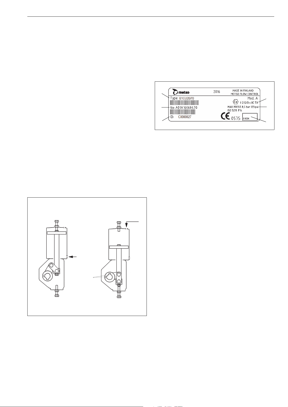
VALVE OPENVALVE CLOSED
opening
2 keyways
pressure
closing
pressure
1
2
3
6
5
4
1 GENERAL
1.1 Scope of the manual
These instructions provide essential information for the use
of Metso B1C series actuators. For more details about
valves, positioners and accessories, refer to the separate
installation, operating and maintenance instructions of the
particular unit.
1.2 Structure and operation
The B1C series actuators are pneumatic cylinder actuators
designed for control and shut-off service.
The linkage bearings have material options. The robust
cast-iron housing efficiently protects the mechanism from
ambient dust and moisture.
The mounting face dimensions of the B1C actuator comply
with the ISO 5211 standard.
The linkage converts the linear motion of the piston into
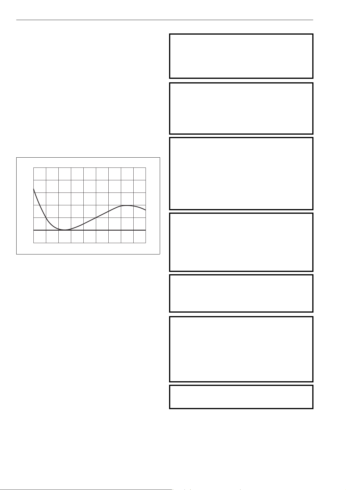
rotation by the actuator shaft. The actuator generates maximum torque when for example a ball or butterfly valve is
closed, and the need for torque is greatest. Another peak is
achieved at 60-80°, when the need for torque on a butterfly
valve caused by the dynamic forces of for example pipe
flows reaches a maximum.
Screws are located in the upper end of the cylinder and in
the lower end of the housing to regulate the length of the
piston stroke and also the rotation angle of the actuator
shaft.
Fig. 1 Operating principle of the actuator
1.3 Actuator markings
The actuator is provided with an identification plate, see
Fig. 2. Identification plate markings are:
1. Type
2. Manufacturing site, date, successive no. (bar code)
3. SO number or ID number (bar code)
4. Checked by
5. Max. supply pressure
6. ATEX category and protection level
Fig. 2 ID plate.
1.4 Specifications
Protection class: IP66, NEMA 4X
Ambient temperatures:
St andar d des ign -20° to 70 °C / -4° to 160 °F
Low tempera ture de sig n -40° to 70 °C / -40° to 160 °F
Hi gh temp eratu re des ign -20° to +120 °C / -4° to 250 °F
Ar cti c temp eratu re des ign -55° to +70 °C / -67° to 158 °F
Maximum supply pressure:
B1C 6...17, 60, 602 8.5 bar / 120 psi
B1C 20...50, 502 10 bar / 145 psi
B1C 75, 752 5 bar / 70 psi
3
Stroke volume, dm
B1C 6 0.33 / 20
B1C 9 0.60 / 37
B1C 11 1.10 / 67
B1C 13 2.30 / 140
B1C 17 4.30 / 262
B1C 20 5.40 / 329
B1C 25 10.50 / 640
B1C 32 21 / 1280
B1C 40 43 / 2620
B1C 50 84 / 5130
B1C 60 121 / 7380
B1C 75 189 / 11500
B1C 502 195 / 11900
B1C 602 282 / 17200
B1C752 441 / 26900
/ in
3
Page 4
4 6 BC 71 en
0 102030405060708090
β / °
1.5
1.4
1.3
1.2
1.1
Mn 1.0
0.9
M
β
/ M
n
Nominal torque, Nm / lbf ft (at max. supply pressure):
B1C 6 135/100
B1C 9 260/190
B1C 11 480/355
B1C 13 1000/740
B1C 17 1900/1400
B1C 20 2700/2000
B1C 25 5300/3910
B1C 32 11000/8115
B1C 40 22000/16225
B1C 50 43000/31715
B1C 60 62000/45730
B1C 75 48000/35400
B1C 502 100000/73755
B1C 602 122000/89980
B1C 752 113000/83350
NB. The torque changes according to supply pressure.
1.6 Safety precautions
CAUTION:
Don’t exceed the permitted values!
Exceeding the permitted pressure value marked on the
actuator may cause damage and lead to uncontrolled
pressure release in the worst case. Damage to the equipment and personal injury may result.
CAUTION:
Don’t dismantle a pressurized actuator!
Dismantling a pressurized actuator leads to uncontrolled pressure release. Shut off the supply pressure and release pressure
from the cylinder before dismantling the actuator.
Otherwise, personal injury and damage to equipment may
result.
CAUTION:
Beware of the cutting movement of the valve!
Hands, other parts of the body, tools or other objects must
not be pushed into the valve’s flow port while it is open.
Also prevent foreign objects from entering the pipes. The
valves function like a cutter while operating. Shut off and
detach the supply of compressed air to the actuator during maintenance.
Otherwise, personal injury or damage to the equipment
may result.
Fig. 3 Output torque as a function of turning angle
1.5 Recycling and disposal
Most actuator parts can be recycled if sorted according to
material. Most parts have material marking. A material list is
supplied with the actuator. In addition, separate recycling
and disposal instructions are available from the manufacturer. An actuator can also be returned to the manufacturer
for recycling and disposal against a fee.
CAUTION:
Don’t use the lever in the torsion arm for manual operation when the actuator is pressurized!
Shut off the supply pressure and release pressure from the
cylinder before using the hand lever. Note also the
dynamic torque caused by the pipe flow.
Otherwise, personal injury and damage to equipment
may result.
CAUTION:
Don’t leave the lever in the torsion arm after manual
operation!
Leaving the lever in the torsion arm can cause personal
injury or damage to the equipment.
CAUTION:
Take the weight of the actuator or valve combination
into account when handling it!
Do not lift the valve combination from the actuator, positioner, limit switch or their piping. Lift the actuator as
directed in Section 2, lifting ropes for a valve combination
should be fastened around it. The weights are shown in
Section 9. Dropping may result in personal injury or damage to the equipment.
CAUTION:
Potential electrostatic charging hazard, do not rub surface
with dry cloth.
Page 5
6 BC 71 en 5
2 TRANSPORTATION, RECEPTION AND
STORAGE
Check the actuator and the accompanying devices for any
damage that may have occurred during transport. Store the
actuator carefully before installation, preferably indoors in a
dry place. Do not take the actuator to the intended location
and do not remove protection plugs from the pipe connections until the actuator is installed.
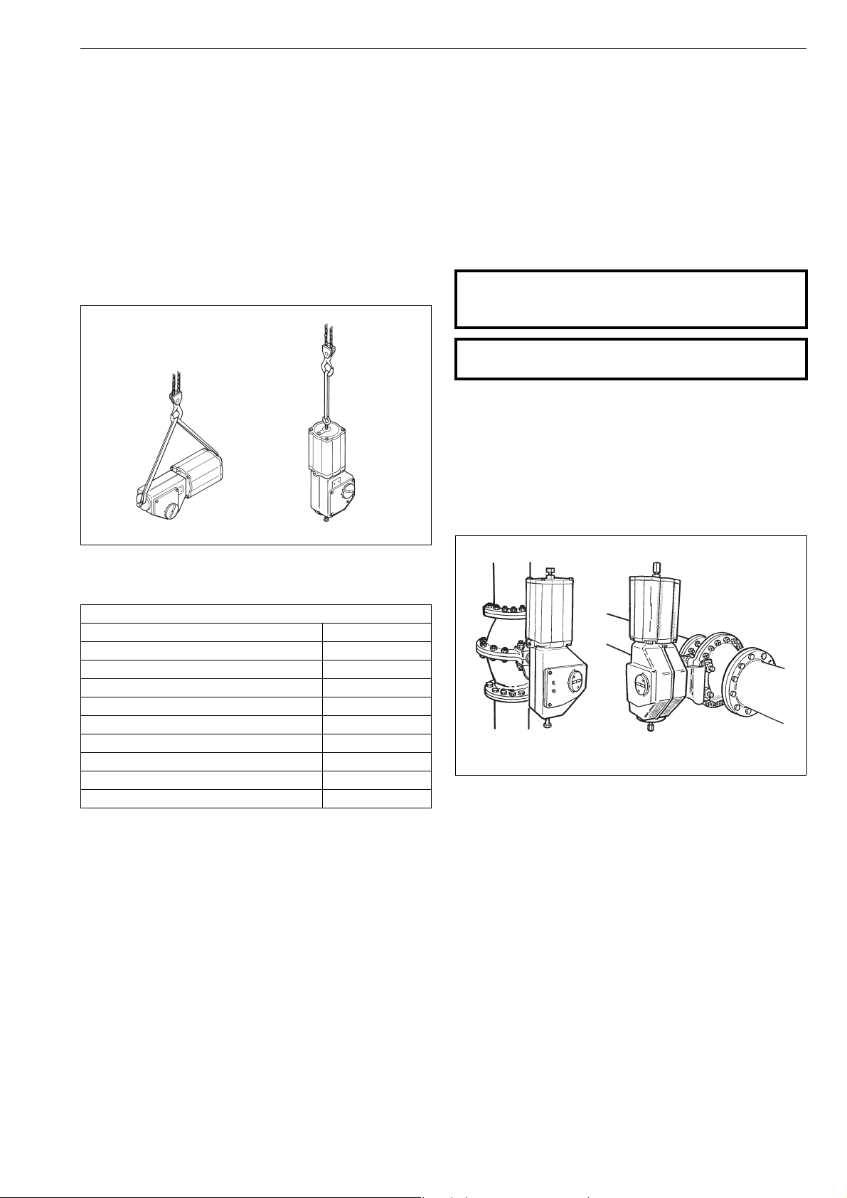
Lift the actuator according to Figure 4:
Horizontally from the stop screws, vertically from a lifting
eyebolt which has been fitted instead of the stop screw. Do
not use eye-bolts for double cylinder actuators. See Section
9 for weights.
3 MOUNTING AND DEMOUNTING
3.1 Actuator gas supply
Dry compressed air or natural gas can be used in doubleacting cylinder actuators; an oil spray is not needed. Clean,
dry and oil-free compressed air must be used in cylinder
actuators equipped with a positioner. The air inlets are
shown in the dimensional drawing in Section 9. The maximum permitted supply pressure is indicated on the identification plate. See also Section 1.4.
3.2 Mounting the actuator on the valve
CAUTION:
Take the weight of the actuator or valve combination
into account when handling it!
CAUTION:
Beware of the cutting movement of the valve!
Install the actuator so that the shaft of the valve or any
other device to be actuated goes into the shaft bore of the
actuator. If the bore is larger than the shaft diameter, use a
keyed shaft adapter sleeve or bushing. There are two keyway slots in the shaft bore of the actuator at an angle of 90°.
These allow the installation position of the actuator to be
changed in relation to the valve. Metso valves have a bevel
at the end of their shafts to facilitate installation.
Fig. 4 Lifting the actuator
Tabl e 1
Lifting tool
Actuator size Tool ID.
BC 12-16 (BC 11) / BJ 8-10, UNC 5/8 H128479
BC 20 (BC 17) / BJ 12, UNC 3/4 H128480
BC 25 / BJ 16, UNC 1 H128481
BC 32 / BJ 20, UNC 1 1/4 H128482
BC 40 / BJ 25, UNC 1 1/2 H128483
BC 50 / BJ 25, UNC 1 3/3 H128484
BC 6-13 / BJ 8-10 / M12 & M16 H096901
BC 17-25 / BJ 12-16 / M20 & M24 H096902
BC 32-50 / BJ 20-32 / M30 & M42 H096903
Fig. 5 Ways to install the actuator
The installation position can be chosen freely, although Metso
recommends one in which the cylinder is vertical. This is the
best way to protect the actuator from impurities in the supply
air or damage caused by water.
When you change the position of the actuator make certain
the indicator arrow has been turned to a position corresponding to that of the valve.
When necessary, lubricate the shaft bore and bushing with
Cortec VCI 369 or an equivalent anti-corrosive agent to prevent it from jamming due to rust.
The actuator must not touch the pipeline, because pipeline
vibration may damage it or interfere with its operation.
In some cases, for instance when the actuator is exceptionally large, the valve has an extended stem or when there is
lot of piping vibration, it may be advisable to support the
actuator. Contact Metso’s Automation business for more
instructions.
Page 6
6 6 BC 71 en
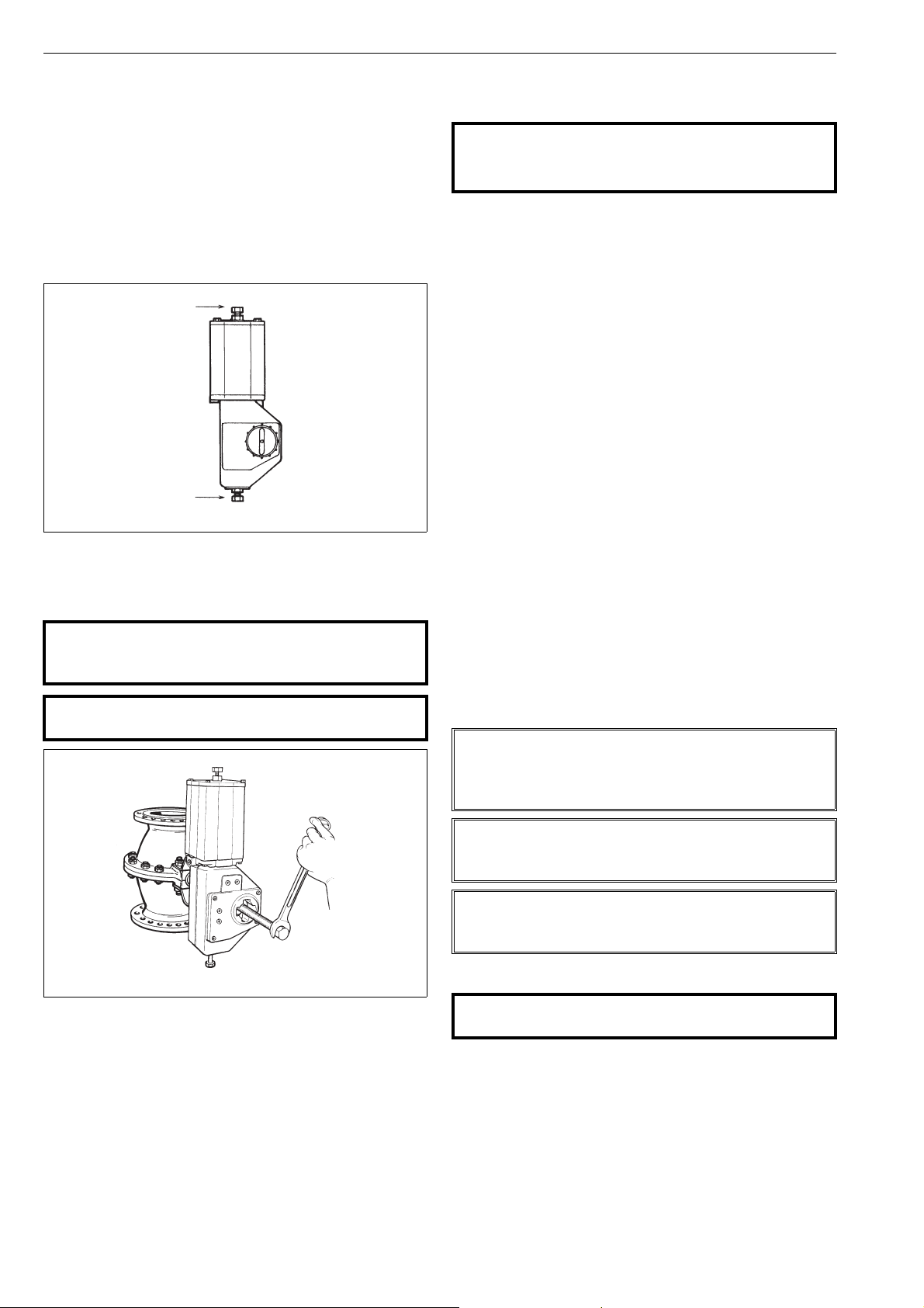
stop screw for
closed position
stop screw for
open position
There are two adjustable stop screws in the actuator; these
stop the movement of the secondary shaft in the extreme
positions. The actuator generates a torque of approximately 1.3 times the nominal torque when the piston is at
the upper end of the cylinder, see also Fig. 3. For some
valves, e.g. butterfly valve, the closing torque and position
is accurate. The stop screw at the cylinder end has to be
adjusted according to right instructions, see separate valve
specific instructions for more detailed information. An Oring (33A) is used for sealing the stop screw in the cylinder
end. See also the instructions of the valve.
Fig. 6 The stop screws in the open and closed positions
3.3 Demounting the actuator from the valve
CAUTION:
Take the weight of the actuator or valve combination
into account when handling it!
CAUTION:
Beware of the cutting movement of the valve!
4 MAINTENANCE
4.1 Maintenance general
CAUTION:
Observe the safety precautions mentioned in Section
1.6 before maintenance!
Although Metso’s Neles actuators are designed to work
under severe conditions, proper preventative maintenance
can significantly help to prevent unplanned downtime and
in real terms reduce the total cost of ownership. Metso recommends inspecting the actuators at least every five (5)
years.
The inspection and maintenance interval depends on the
actual application and process condition. The inspection
and maintenance intervals can be specified together with
your local Metso experts.
During this periodic inspection the parts detailed in the
Spare Part Set should be replaced. Time in storage should
be included in the inspection interval.
Maintenance can be performed as presented below. If
maintenance assistance is required, please contact your
local Metso office.
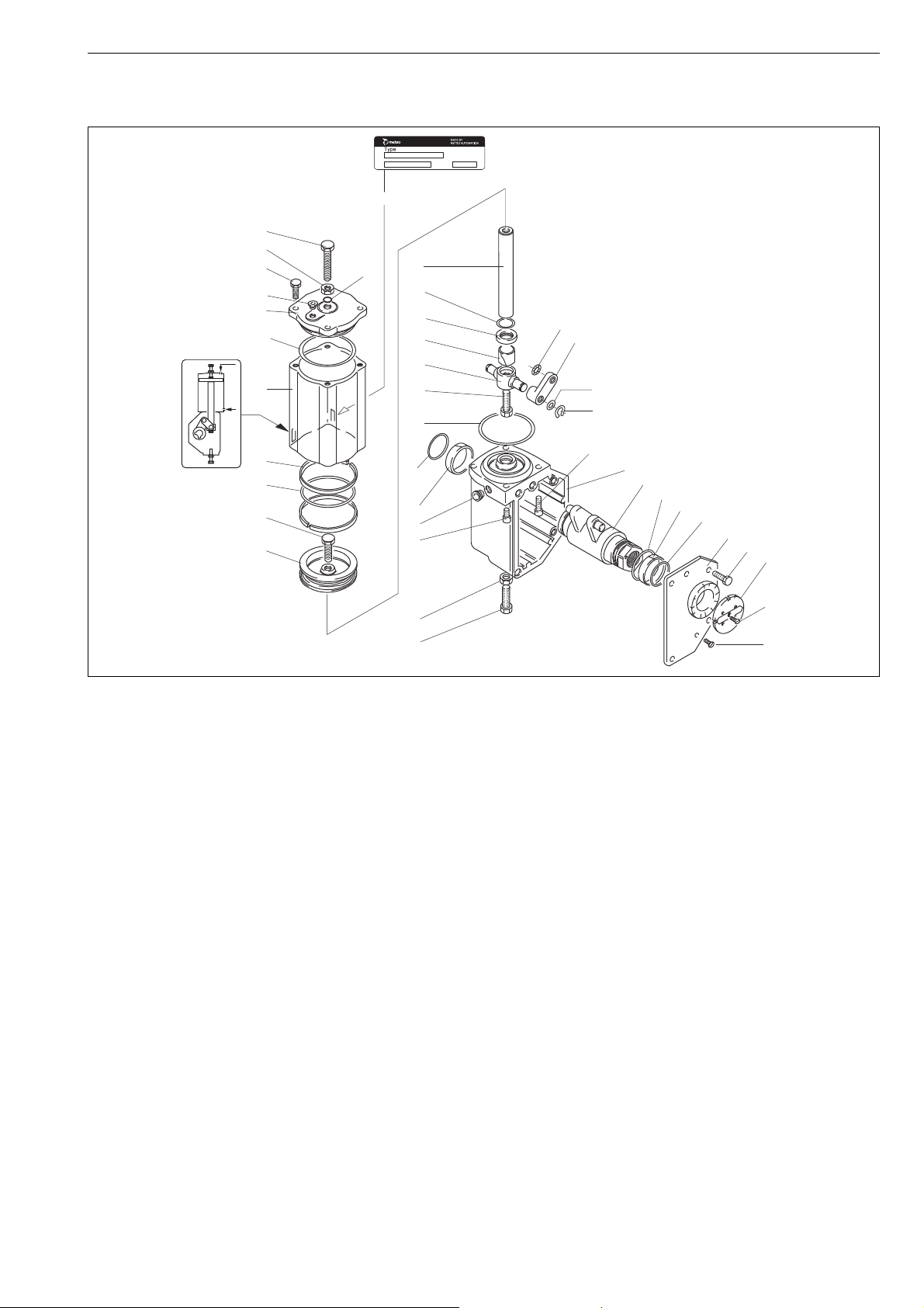
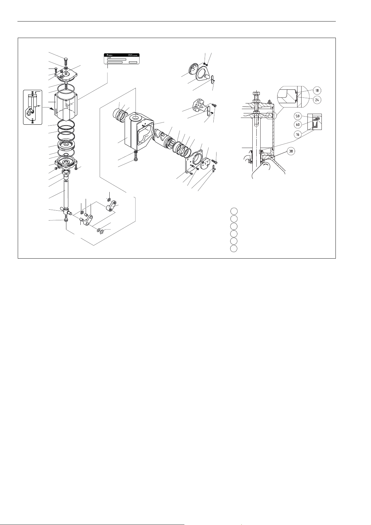
The part numbers in the text refer to the exploded view and
to the parts list in Section 8, unless otherwise stated.
Under severely corrosive conditions, the linkage system
inside the housing should be lubricated at six month intervals. Use Cortec VCI 369 anti-corrosive agent or the equivalent. The housing may also be half filled with semi-fluid
water-repellant grease (e.g. Mobilux EP2) while the piston
rod is in the lower position.
If you remove the stop screw, adjust the limits after
lubrication or grease filling!
NOTE:
In order to ensure safe and effective operation, always use
original spare parts to make sure that the actuator functions as intended.
Fig. 7 Removing the actuator with the extractor
The actuator must be depressurized and the supply air
pipes disconnected. Unscrew the actuator-side screws of
the bracket and pull the actuator off the valve shaft. This is
best done using a specific extractor, see Fig. 7 and Section
6. Note the mutual positioning of the valve and the actua-
tor to ensure correct functioning after reassembly.
NOTE:
When sending goods to the manufacturer for repair, do
not disassemble them.
NOTE:
For safety reasons, replace bolting if the threads are damaged, have been heated, stretched or corroded.
4.2 Replacement of piston seals
CAUTION:
Don’t dismantle a pressurized actuator!
Replacement of all seals and soft bearings is recommended
when the actuator has been disassembled for maintenance.
Operate the actuator so that the piston goes to the
outermost end of the cylinder. Release the pressure
from the cylinder.
Remove the cover of the housing (2).
Page 7
6 BC 71 en 7
Press the bearing
strip like this to
facilitate installation
16
22
18
24
BC9...16
BC50...75
18
24
18
24
BC17...40
*)
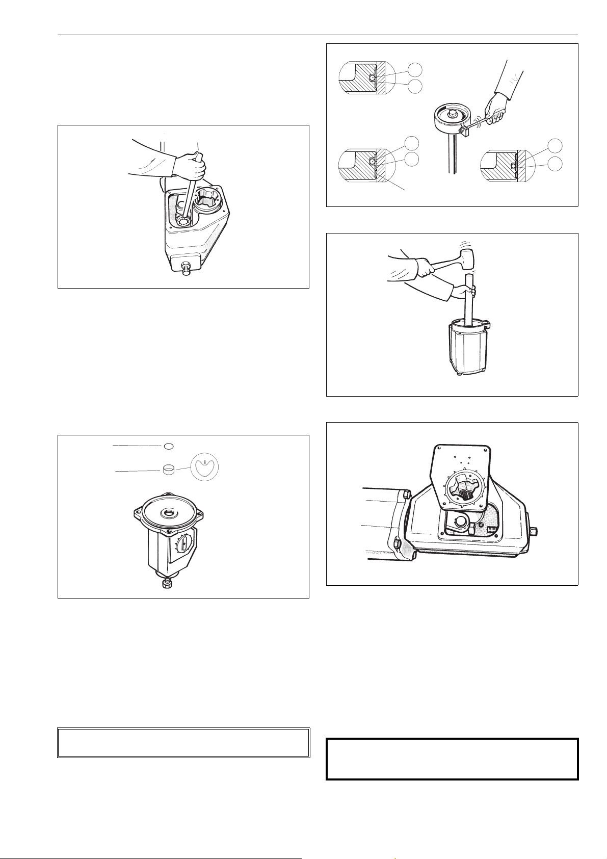
Loosen the fastening screw (29) of the bearing unit
and the fastening screws of the cylinder (31) from
the cylinder base (6). Should the piston turn with the
screw (29), remove the end of the cylinder (44) and
stop the turning with the piston fastening screw (28).
See Figure 8.
Fig. 10 Tightening piston seals with a tie ring
Fig. 8 Opening the fastening screw of the actuator bear-
ing unit
Remove the cylinder and the piston, including the
rod.
Remove the old seals and the O-ring (24, 18, 19).
Remove the O-ring (16) and the bearing (22). Clean
the seal space.
Lubricate the seal space and the new O-ring with
Unisilikon L250L or equal silicone grease. Install the
new bearing and O-ring. See Figure 9.
Fig. 9 Mounting the piston rod bearing and seal
Clean the piston seal groove and lubricate with a
thin layer of Cortec VCI 369.
Place the O-ring (18) under the piston seals.
Locate the seals (24) around the piston so that the
ends of the strips come on opposite sides. Tighten
the strips with the tie ring as shown in Figure 10. The
strips marked with an asterisk (*) may be cut 1.53 mm shorter to facilitate assembly.
NOTE:
The inside surface of the cylinder must be free of any grease!
Knock or press the piston through the tie ring with a
press, Fig. 11.
Fig. 11 Placing the piston in the cylinder
Fig. 12 Mounting the cover on the housing
Mount the O-ring (19) and the cylinder and piston.
Note the location of the air inlet: use the air inlet of
the cylinder base as a guide. Tighten the screws (31).
See Table 1 for torques.
Apply locking sealant e.g. Loctite 225 to the threads
of the fastening screw (29) of the bearing unit and
tighten it. See Table 1 for torque.
Fasten the housing cover temporarily so that the link-
age bearings (3) function, but the linkage is still visible,
Fig. 12. Note the grounding rings (3A, 4A).
CAUTION:
Keep your fingers, tools or other items out of the housing while operating the actuator with the cover open!
Page 8
8 6 BC 71 en
Check the assembly of the cylinder to the cylinder
base and end. Connect the supply air to the cylinder
temporarely via a shut-off valve.
Operate the actuator and check the function of the
cylinder. Also check that the linkage bearings function properly. Remove the air supply and release
pressure from the cylinder.
Lubricate the linkage throughout with Cortec VCI
369 or an equivalent anti-corrosive agent to prevent
it from jamming due to rust.
Spread the sealant (e.g. silicone sealant) on the sur-
faces between the housing and the cover. Fasten the
cover, Fig. 12. See Table 1 for torques.
Mount the actuator to the valve and adjust the limits.
If you wish to remove the cylinder base, you will need a spe-
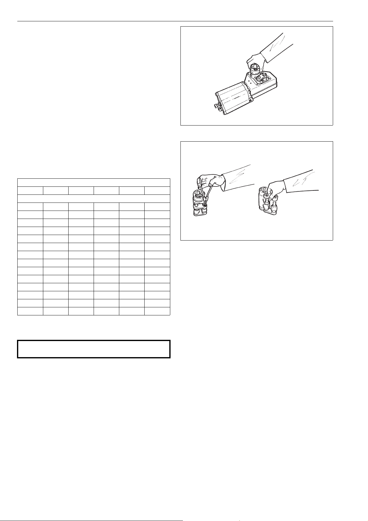
Fig. 13 Removing the linkage from the housing
cial tool to open the lock nut (35), see Section 6. The nut
must be secured with e.g. Loctite 225 or equal liquid glue
when remounted.
Table 2 Tightening torques for screws
Tor que , Nm
Item 28 29 30 31 35
Actuator
B1C 63535127
B1C 9 90 35 8 12 150
B1C 11 170 90 8 18 180
B1C 12 170 170 12 18 200
B1C 13 300 170 12 40 200
B1C 16 300 300 12 40 250
B1C 17 700 300 12 80 250
B1C 20 700 700 20 80 400
B1C 25 1100 1100 30 80 800
B1C 32 2000 2000 70 80 1500
B1C 40 2000 2000 70 200 2000
B1C 50 3400 3400 150 250 3000
B1C 60 3400 3400 150 250 3000
B1C 75 3400 3400 150 250 3000
4.3 Replacement of linkage bearings and O-rings
CAUTION:
Don’t dismantle a pressurized actuator!
Fig. 14 Dismantling the linkage
The bearings (20, 21) of the connection arm (4) of B1C6-25
actuators are fastened with a press-on fit so that the entire
connection arm assembly is replaced instead of the bearings. The bearings in actuators B1C32-75 are removable.
Remove the lever bearings (23), the O-rings (17) and
the grounding ring (3A).
Clean the parts of the levers and lubricate the bear-
ing and seal surfaces with Cortec VCI 369.
Install the grounding ring (3A), the lever bearings
(23) and the O-rings (17). The grounding rings (3A
and 4A) are needed to meet the ATEX requirements.
Assemble the linkage and install in the housing. See
Figure 13 for the correct position. Note the ring (4A).
Remove the actuator from the valve
Guide the actuator so that the piston is at the outer-
most end of the cylinder. Release the pressure from
the cylinder.
Remove the housing cover (2).
Loosen the fastening screw (29) of the bearing unit
(5), see Figure 8.
Turn the lever (3) so that the bearing unit is detached
from the piston rod (10). Lift the entire lever system
out of the housing, Figure 13.
Remove the lock rings (36) and the support rings
(37).
Loosen the connection arms (4) and ring (4A), clean
Apply locking sealant e.g. Loctite 225 to the threads
of the fastening screw (29) of the bearing unit and
tighten it. See Table 1 for torque.
Lubricate the levers throughout with Cortec VCI 369
anti-corrosive.
Spread the sealant (e.g. silicone sealant) on the sur-
faces between the housing and the cover. Fasten the
cover, Fig. 12. See Table 1 for torques.
Operate the actuator and check that it moves cor-
rectly.
Cortec VCI 369 must be applied at six-month intervals in
damp conditions where corrosion is likely. Grease filling the
housing should also be considered. See Section 4.1.
them and check the condition of the bearings, see
Figure 14.
Page 9
6 BC 71 en 9
4.4 Maintenance of a B1CM actuator
CAUTION:
Don’t use the lever in the torsion arm for manual operation when the actuator is pressurized!
CAUTION:
Don’t leave the lever in the torsion arm after manual
operation!
The structure of the B1CM actuator is the same, except for
the manual operation lever connected with lever arm (3).
See the exploded view, Section 8.
Maintenance as in Sections 4.1 and 4.2.
4.5 Maintenance of B1C502-752 actuators
The structure of the B1C502-752 actuators is in principle the
same as a normal B1C actuator. In order to ensure a high
operating torque, the equipment is fitted with two cylinders connected to the secondary shaft.
For maintenance see Sections 4.1 and 4.2.
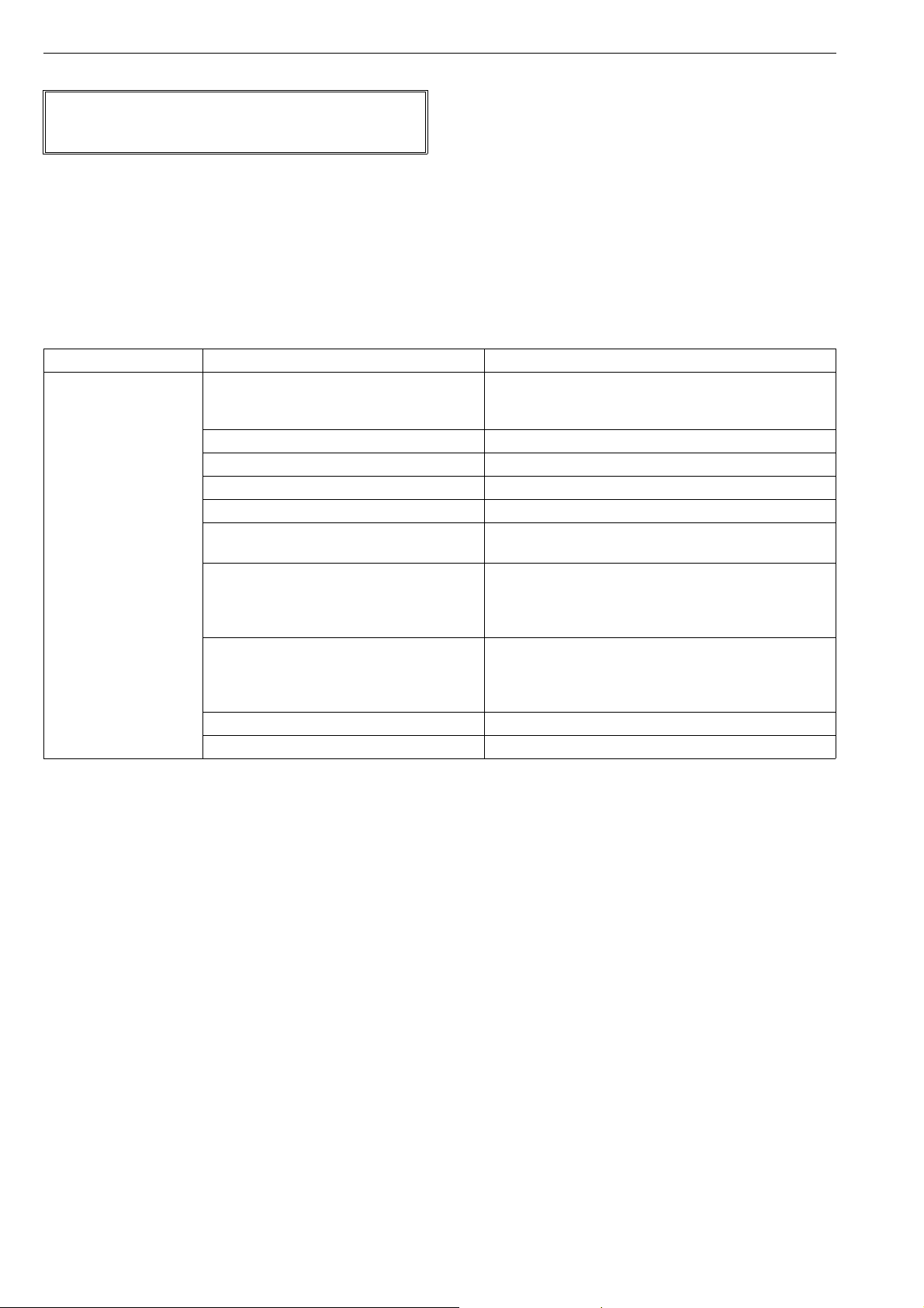
5 MALFUNCTIONS
Table 2 lists malfunctions that might occur after prolonged
use.
6 TOOLS
For maintenance of the actuator, you will need a few special
tools in addition to the usual ones. The following can be
ordered from the manufacturer:
For actuator removal:
- Extractor (Table 3)
For piston seal installation:
- Tie ring (Table 4)
For cylinder base removal:
- Lock nut key (Table 5)
Table 3 Extractor tools
Actuator size Tool ID.
BC/BJ 6 303821
BC 8-11 / BJ 8-10 8546-1
BC 12-17 / BJ 12-16 8546-2
BC/BJ 20 8546-3
BC/BJ 25 8546-4
BC/BJ 32 8546-5
BC 40 / BJ 322 8546-6
BC 50 8546-7
BC 502 8546-8
Table 4 Mounting Collars
Actuator size Tool ID.
BC 6-8 7814-1
BC 9-10 7814-2
BC 11-12 / BJ 8 7814-3
BC 13-16 / BJ 10 7814-4
BC 17-20 / BJ 12 7814-5
BC 25 / BJ 16 7814-6
BC 32 / BJ 20 7814-7
BC 40 / BJ 25 7814-8
BC 50, 502 / BJ 32, 322 7814-9
BC 60, 602 cylinder Ø 600 7814-10
BC 75, 752 7814-11
Table 5 Shaft nut tools
Actuator size Tool ID.
BC/BJ 8 260155
BC 10-11 / BJ 10 260156
BC 12-13 / BJ 12 260157
BC 16-17 / BJ 16 260172
BC/BJ 20 260196
BC/BJ 25 260195
BC 32 / BJ 32, 322 261153
BC 40 261154
BC 50, 502 261155
Page 10
10 6 BC 71 en
7 ORDERING SPARE PARTS
NOTE:
Use only original spare parts. This ensures proper functioning
of the actuator.
When ordering spare parts, always include the following
information:
type code, sales order number, serial number
number of the parts list, part number, name of the
part and quantity required
This information can be found from the identification plate
or documents.
Table 6 Possible malfunctions
Symptom Possible cause Action
Irregular or slow operation Low supply pressure Make sure that supply pressure complies with minimum
torque required by valve.
Check that supply air pipes are large enough.
Positioner malfunction Check the operation of the positioner.
Valve malfunction Check that valve functions properly without actuator.
Wrong size actuator Contact the manufacturer for checking the size.
Leak in piston or piston rod seal Replace seals. See Section 4.1.
Cylinder damaged by impurities Note installation position recommendation.
Cylinder damage always requires replacement.
Worn-out actuator bearings Check condition of bearings in accordance with Section 4.2.
Replace the bearings if necessary. If the frequency of
operation is high, the bearings and piston seals should be
replaced at regular intervals, max. of 500 000 operations..
Linkage rusted in difficult damp conditions Clean the linkage and replace the bearings. Lubricate the
housing regularly and apply grease as in Section 4 .1. If
water collects in the housing, bore a hole in the lower part
of the housing (ø5 mm).
The fastening screw in the bearing unit is loose Tighten screw. Lock with Loctite 225 or equal liquid glue.
Play in the joint between actuator and valve Replace necessary parts.
Page 11
6 BC 71 en 11
8 EXPLODED VIEWS AND PARTS LISTS
8.1 Actuators B1C 6
39
26
33
45
42
44
19
33A
8
10
16
49
22
29
60
4A
4, 20, 21
5
37
36
24
18
28
9
17
23
42
31
34
27
Item Qty Description Spare part category
11Housing
21Cover 3
31Lever arm 2 **
3A 1 Antistatic ring 2 **
4 2 Connection arm 2 **
4A *** 1 Antistatic ring 2 **
5 1 Bearing unit 2 **
71Pointer cover 3
81Cylinder 3
91Piston 3
10 1 Piston rod 3
16 1 O-ring 1 *
17 2 O-ring 1 *
18 1 O-ring 1 *
19 1 O-ring 1 *
20 2 Bearing 2 **
21 2 Bearing 2 **
22 1 Bearing 1 *
23 2 Bearing 1 *
24 2 Piston seal 1 *
26 1 Stop screw 3
27 1 Stop screw 3
28 1 Screw
67
1
3
3A
23
17
2
30
7
32
58
Item Qty Description Spare part category
29 1 Screw
30 1 Screw
31 3 Screw
32 2 Screw
33 1 Nut 3
33A 1 O-ring 3
34 1 Nut 3
36 2 Lock ring (**)
37 2 Support ring (**)
39 1 ID plate
42 2 Plug
44 1 Cylinder end 3
45 4 Screw
49 1 Bushing
58 1 Pressure outlet valve
60 1 O-ring
62 1 Screw
67 1 Screw
*) Delivered as a set
**) Leverage assembly, also available as separate part.
Parts 20 and 21 are not available separately. They are delivered with part 4
as a set only.
(**) Belongs to leverage assembly, not recommended as separate part
***) With long-run option
Spare part set category 1: Recommended soft parts for inspection and maintenance (to be replaced always after disassembling the actuator)
Spare part category 2: Leverage repair
Spare part category 3: Complete overhaul (for complete overhaul parts of all 3 categories are needed)
Page 12
12 6 BC 71 en
26
33
31
44
42
28
19
8
24
18
9
19
16, 16A
6
42
35
22
10
5
29
1
34
27
7
47
61
62
7
61
62
32
41
30
58
61
62
41
3
23
25
17
2
7
32
48
32
39
17
25
23
21
20
4
37
36
B1C
B1C 9 – 25
4, 20, 21
B1CM 25 – 32
B1CM 9 – 20
3A
31
33A
4A
4A
B1CU_/_A
Parts for Arctic temperature design
model B1C_/_A.
Special items with circled numbers.
B1CU_/_A
Arctic design special items: 16, 18, 24, 38,
59 and 60.(*
Item Qty Description
16 1 Lip-seal
18 2 Lip-seal
24 1 Piston ring
38 1 O-ring
59 1 Retainer ring
60 1 Spacer ring
8.2 Actuators B1C 9-32
Item Qty Description Spare part category
11Housing
21Cover 3
3 1 Lever arm 2 **
3A 1 Antistatic ring 2 **
4 2 Connection arm 2 **
4A *** 1 Antistatic ring 2 **
51Bearing unit 2
61Cylinder base 3
71Pointer cover 3
81Cylinder 3
91Piston 3
10 1 Piston rod 3
16 1 O-ring 1 *
16A 1 O-ring 1 *
17 2 O-ring 1 *
18 1 O-ring 1 *
19 2 O-ring 1 *
20 2 Bearing 2 ** (size 32: 1 *)
21 2 Bearing 2 ** (size 32: 1 *)
22 1, 2 Bearing 1 *
23 2 Bearing 1 *
24 2, 3 Piston seal 1 *
25 2 Bushing 3
26 1 Stop screw 3
27 1 Stop screw 3
Spare part set category 1: Recommended soft parts for inspection and maintenance (to be replaced always after disassembling the actuator)
Spare part category 2: Leverage repair
Spare part category 3: Complete overhaul (for complete overhaul parts of all 3 categories are needed)
Item Qty Description Spare part category
28 1 Screw
29 1 Screw
30 4 Screw
31 8, 12 Screw
32 2 Screw
33 1 Nut 3
33A 1 O-ring 3
34 1 Nut 3
35 1 Lock nut 3
36 2 Lock ring (**)
37 2 Support ring (**)
39 1 ID plate
41 Plug
42 Plug
44 1 Cylinder end 3
47 1 Torsion arm
48 2 Washer
58 1 Pressure outlet valve
61 1 Direction arrow 3
62 1 Screw
*) Delivered as a set
**) Leverage assembly, also available as separate part.
Actuator sizes 9–25: Parts 20 and 21 are not available separately.
They are delivered with part 4 as a set only.
(**) Belongs to leverage assembly, not recommended as separate part
***) With long-run option and standard contruction size 32
Page 13
6 BC 71 en 13
45
46
31
44
42
19
24
28
9
18
8
19
16, 16A
6
42
35
22
10
5
29
17
25
23
1
34
27
41
30
7
47
61
62
20
4
21
37
36
48 32
3
23
25
17
2
7
32
61
62
58
39
26
33
B1MC 40
3A
33A
4A
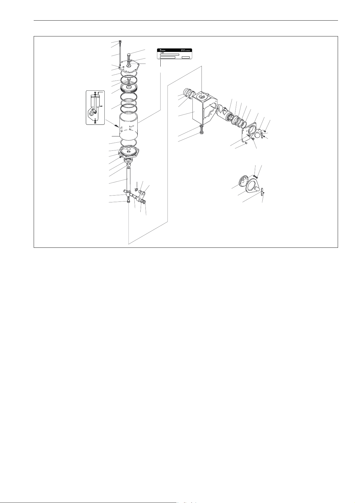
8.3 Actuators B1C 40-75
Item Qty Description Spare part category
11Housing
21Cover 3
31Lever arm 2 **
3A 1 Antistatic ring 2 **
4 2 Connection arm 2 **
4A 1 Antistatic ring 2 **
5 1 Bearing unit 2 **
61Cylinder base 3
71Pointer cover 3
81Cylinder 3
91Piston 3
10 1 Piston rod 3
16 1 O-ring 1 *
16A 1 O-ring 1 *
17 2 O-ring 1 *
18 1 O-ring 1 *
19 2 O-ring 1 *
20 2 Bearing 1 *
21 2 Bearing 1 *
22 2 Bearing 1 *
23 2 Bearing 1 *
24 3, 4 Piston seal 1 *
25 2 Bushing 3
26 1 Stop screw 3
27 1 Stop screw 3
Spare part set category 1: Recommended soft parts for inspection and maintenance (to be replaced always after disassembling the actuator)
Spare part category 2: Leverage repair
Spare part category 3: Complete overhaul (for complete overhaul parts of all 3 categories are needed)
Item Qty Description Spare part category
28 1 Screw
29 1 Screw
30 6 Screw
31 6 Stud
32 2 Screw
33 1 Nut 3
33A 1 O-ring 3
34 1 Nut 3
35 1 Lock nut 3
36 2 Lock ring (**)
37 2 Support ring (**)
39 1 ID plate
41 Plug
42 Plug
44 1 Cylinder end 3
45 6 Nut
46 6 Washer
47 1 Torsion arm
48 2 Washer
58 1 Pressure outlet valve
61 1 Direction arrow 3
62 1 Screw
*) Delivered as a set
**) Leverage assembly, also available as separate part
(**) Belongs to leverage assembly, not recommended as separate part
Page 14
14 6 BC 71 en
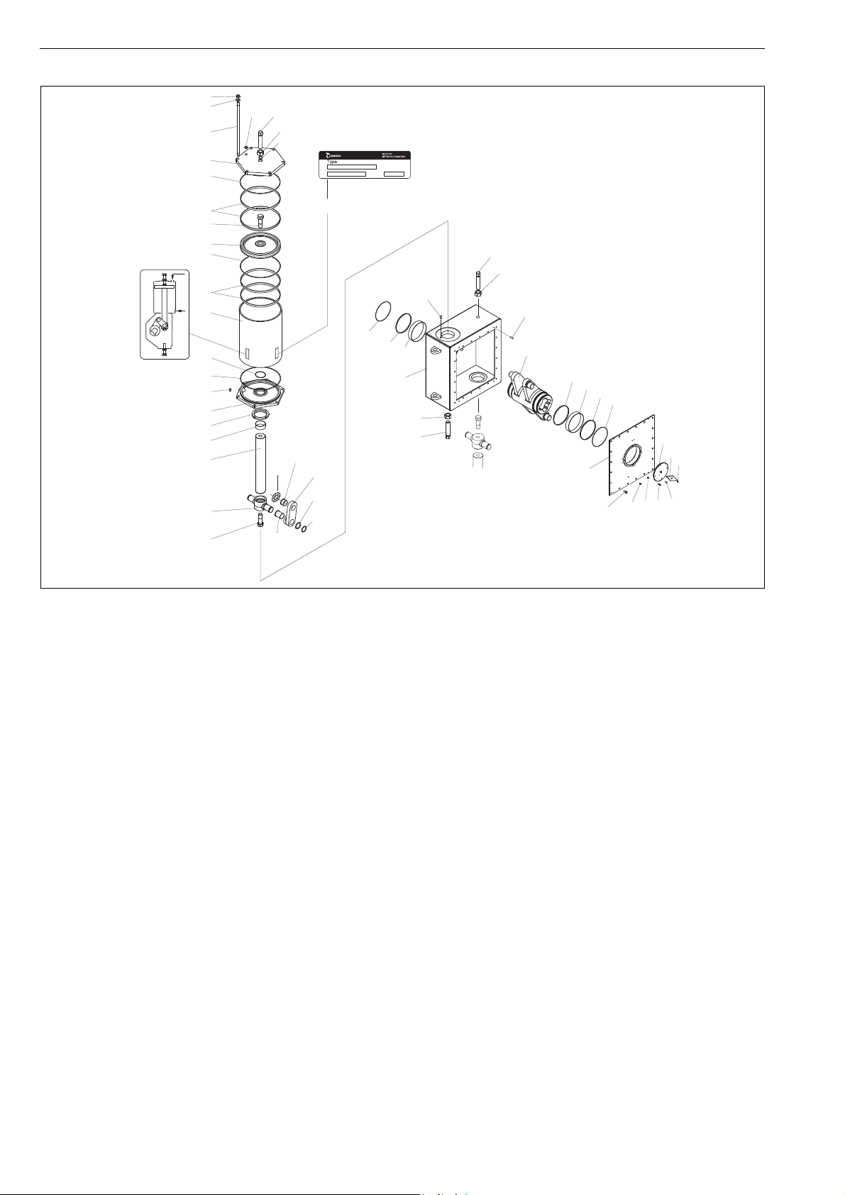
8.4 Actuators B1C 502-752
45
46
31
44
19
42
26
33
33A
24
28
9
18
24
8
16
19
42
6
35
22
10
5
29
4A
21
39
27
34
63
65
17
25
23
1
34
27
20
4
37
36
3
3A
23
25
17
7
61
2
41
30
62
32
58
96
Item Qty Description Spare part category
11Housing
21Cover 3
3 1 Lever arm 2 **
3A 1 Antistatic ring 2 **
4 4 Connection arm 2 **
4A 1 Antistatic ring 2 **
52Bearing unit 2 **
62Cylinder base 3
71Pointer cover 3
82Cylinder 3
92Piston 3
10 2 Piston rod 3
16 2 O-ring 1 *
17 2 O-ring 1 *
18 2 O-ring 1 *
19 4 O-ring 1 *
20 4 Bearing 1 *
21 4 Bearing 1 *
22 4 Bearing 1 *
23 2 Bearing 1 *
24 8 Piston seal 1 *
25 2 Bushing 3
26 2 Stop screw 3
27 2 Stop screw 3
28 2 Screw
Item Qty Description Spare part category
29 2 Screw
30 20 Screw
31 12 Stud
32 2 Screw
33 2 Nut 3
33A 2 O-ring 3
34 2 Nut 3
35 2 Lock nut 3
36 4 Lock ring (**)
37 4 Support ring (**)
39 1 ID plate
41 4 Plug
42 4 Plug
44 2 Cylinder end 3
45 12 Nut
46 12 Washer
58 1 Pressure outlet valve
61 1 Direction arrow
62 2 Screw 3
63 2 Pin
65 4 Pin
96 4 Screw
*) Delivered as a set
**) Leverage assembly, also available as separate part
(**) Belongs to leverage assembly, not recommended as separate part
Spare part set category 1: Recommended soft parts for inspection and maintenance (to be replaced always after disassembling the actuator)
Spare part category 2: Leverage repair
Spare part category 3: Complete overhaul (for complete overhaul parts of all 3 categories are needed)
Page 15
6 BC 71 en 15
NPT
G
NPT
F
max
VY
X
A
A
L
K
R
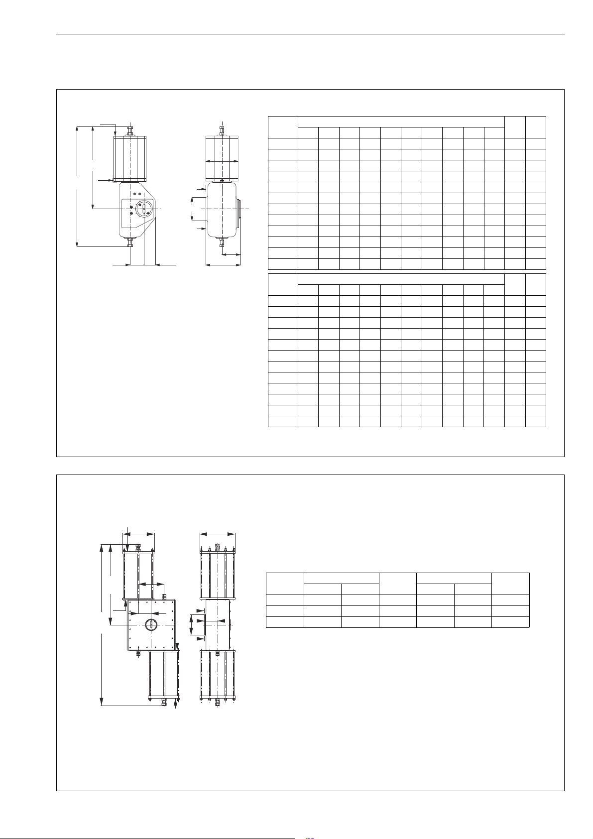
*) Dimensions K and R are for Metso accessories interface.
Dimensions K1 and R1 are for VDI/VDE 3845 interface (type code "U").
Type Dimensions, mm NPT kg
X G F V Y L K* K1 R* R1
B1C6 90 270 395 36 46 80 138 138 80 80 1/4 4.2
B1C9 110 315 450 43 50 80 130 140 72 81 1/4 9.6
B1C11 135 375 535 51 50 95 144 154 80 89 3/8 16
B1C13 175 445 640 65 65 120 175 190 94 109 3/8 31
B1C17 215 555 785 78 70 137 207 222 111 126 1/2 54
B1C20 215 590 880 97 80 145 240 262 125 147 1/2 73
B1C25 265 725 1075 121 110 180 300 304 162 166 1/2 131
B1C32 395 920 1370 153 146 280 376 379 201 204 3/4 256
B1C40 505 1150 1670 194 185 320 449 449 224 224 3/4 446
B1C50 610 1390 2060 242 195 350 541 543 266 268 1 830
B1C60 725 1390 2060 242 195 350 541 543 266 268 1 1080
B1C75 875 1390 2060 242 195 350 541 543 266 268 1 1190
Type Dimensions, in NPT lb
XGFVYLK*K1R*R1
B1C6 3.54 10.60 15.60 1.42 1.81 3.15 5.43 5.43 3.15 3.15 1/4 9
B1C9 4.33 12.40 17.70 1.69 1.97 3.15 5.12 5.51 2.83 3.19 1/4 21
B1C11 5.31 14.80 21.10 2.01 1.97 3.74 5.67 6.06 3.15 3.50 3/8 35
B1C13 6.89 17.50 25.20 2.56 2.56 4.72 6.89 7.48 3.70 4.29 3/8 68
B1C17 8.46 21.90 30.90 3.07 2.76 5.39 8.15 8.74 4.37 4.96 1/2 119
B1C20 8.46 23.20 34.70 3.82 3.15 5.71 9.45 10.31 4.92 5.79 1/2 161
B1C25 10.43 28.50 42.30 4.76 4.33 7.09 11.81 11.97 6.38 6.54 1/2 289
B1C32 15.55 36.20 53.90 6.02 5.75 11.0 14.80 14.92 7.91 8.03 3/4 564
B1C40 19.88 45.30 65.70 7.64 7.28 12.60 17.68 17.68 8.82 8.82 3/4 983
B1C50 24.02 54.70 81.10 9.53 7.68 13.78 21.30 21.38 10.47 10.55 1 1829
B1C60 28.54 54.70 81.10 9.53 7.68 13.78 21.30 21.38 10.47 10.55 1 2380
B1C75 34.45 54.70 81.10 9.53 7.68 13.78 21.30 21.38 10.47 10.55 1 2620
1 NPT
1 NPT
1 NPT
1 NPT
A
A
X
1
265
530
X
2
280
2960
1480
480
20.86
18.90
116.50
10.07
58.30
11.02
Type Dimensions, mm Weight
kg
Dimensions, in Weight
lb
X1 X2 X1 X2
502 540 610 1665 21.3 24.0 3663
602 635 725 2170 25.0 28.5 4780
752 813 875 2300 32.0 34.5 5070
9 DIMENSIONS AND WEIGHTS
9.1 Actuator B1C
Page 16
16 6 BC 71 en
B
P
S
O
U
B
M
B
S
U
B
M
P
O
K
L
B1C6...25 B1C32...752
DIRECTION A - A DIRECTION B - BDIRECTION A - A
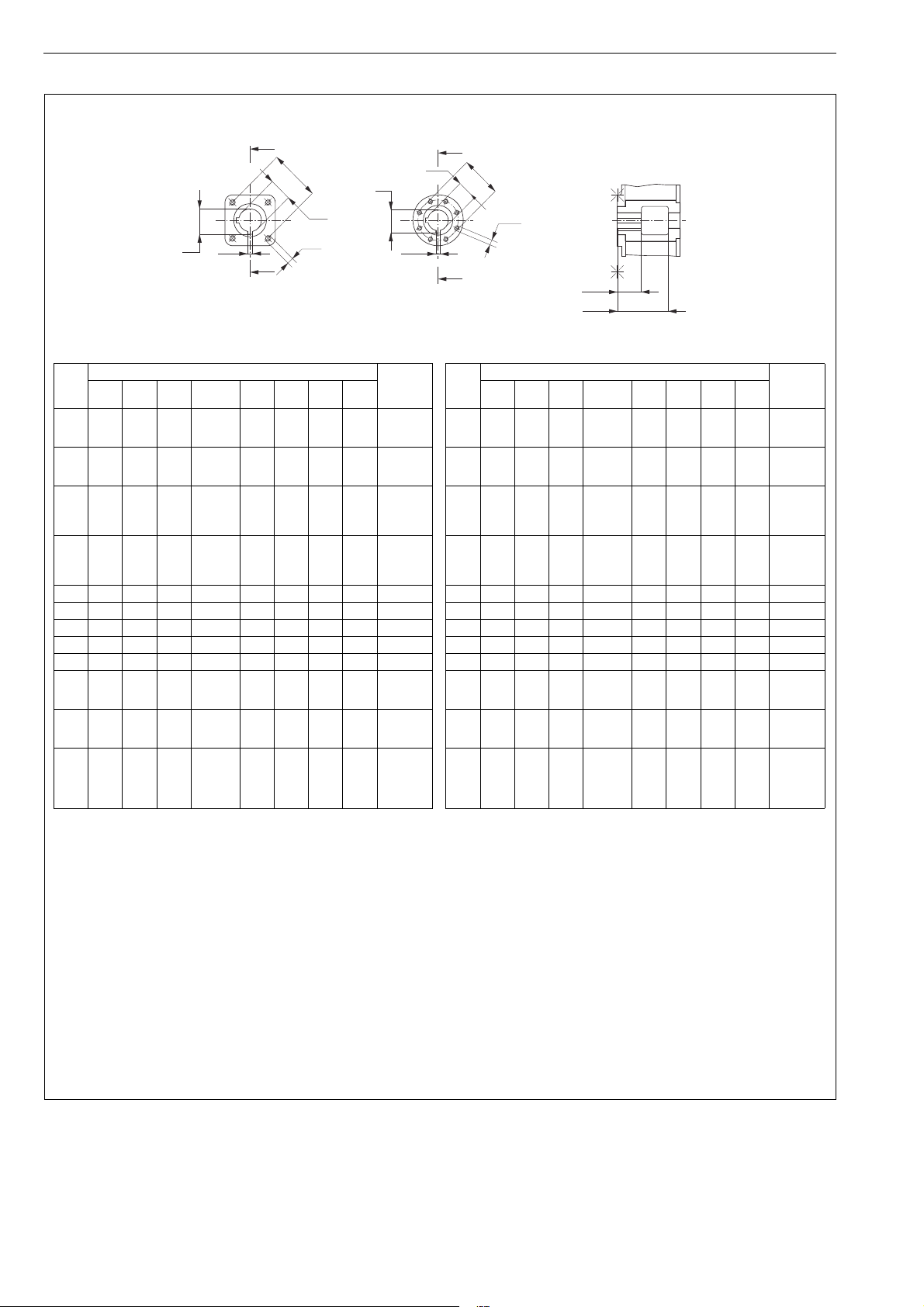
B1C Dimensions, mm Mounting
face
O
(H8)
MP K
(keyway)
LSUN
61520
25
4.76
4.76
6.35
17.0
23.3
27.9
40 90 50 M6 4 F05
61520
25
4.76
4.76
6.35
17.0
23.3
27.9
40 90 70 M8 4 F07
9
15
20
25
35
4.76
4.76
6.35
9.52
17.0
23.3
27.9
39.3
50 90 70 M8 4 F07
11
20
25
35
40
4.76
6.35
9.52
9.52
23.3
27.9
39.3
44.4
60 105 102 M10 4 F10
13 55 12.70 60.8 75 130 125 M12 4 F12
17 55 12.70 60.8 80 120 140 M16 4 F14
20 70 19.05 78.3 105 195 140 M16 4 F14
25 95 22.22 105.5 140 235 165 M20 4 F16
32 105 25.40 116.3 155 280 254 M16 8 F25
4095105
120
22.22
25.40
31.75
105.5
116.3
133.9
180 340 298 M20 8 F30
50
60
75
120
135
31.75
31.75
133.9
149.2
200 430 356 M30 8 F35
502
602
752
120
135
150
165
180
31.75
31.75
31.75
38.10
44.45
133.9
149.2
166.8
182.0
199.4
250 470 406 M36 8 F40
B1C Dimensions, in Mounting
face
O
(H8)
MP K
(keyway)
LSUN
6
0.59
0.79
0.98
0.19
0.19
0.25
0.67
0.92
1.10
1.57 3.54 1.97 M6 4 F05
6
0.59
0.79
0.98
0.19
0.19
0.25
0.67
0.92
1.10
1.57 3.54 2.76 M8 4 F07
9
0.59
0.79
0.98
1.38
0.19
0.19
0.25
0.37
0.67
0.92
1.10
1.55
1.97 3.54 2.76 M8 4 F07
11
0.79
0.98
1.38
1.57
0.19
0.25
0.37
0.37
0.92
1.10
1.55
1.75
2.36 4.13 4.02 M10 4 F10
13 2.17 0.50 2.39 2.95 5.12 4.92 M12 4 F12
17 2.17 0.50 2.39 3.15 4.72 5.51 M16 4 F14
20 2.76 0.75 3.08 4.13 7.68 5.51 M16 4 F14
25 3.74 0.87 4.15 5.51 9.25 6.50 M20 4 F16
32 4.13 1.00 4.58 6.10 11.02 10.00 M16 8 F25
40
3.74
4.13
4.72
0.87
1.00
1.25
4.15
4.58
5.27
7.09 13.39 11.73 M20 8 F30
50
60
75
4.72
5.31
1.25
1.25
5.27
5.87
7.87 16.93 14.02 M30 8 F35
502
602
752
4.72
5.31
5.91
6.50
7.09
1.25
1.25
1.25
1.50
1.75
5.27
5.87
6.57
7.17
7.85
9.84 18.50 15.98 M36 8 F40
9.2 Attachment dimensions
Page 17
6 BC 71 en 17
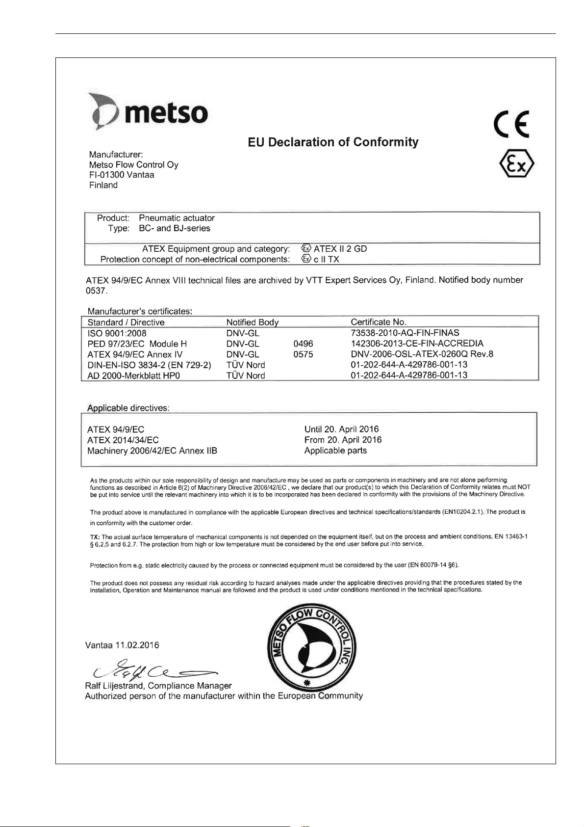
10 EC DECLARATION OF CONFORMITY
Page 18
18 6 BC 71 en
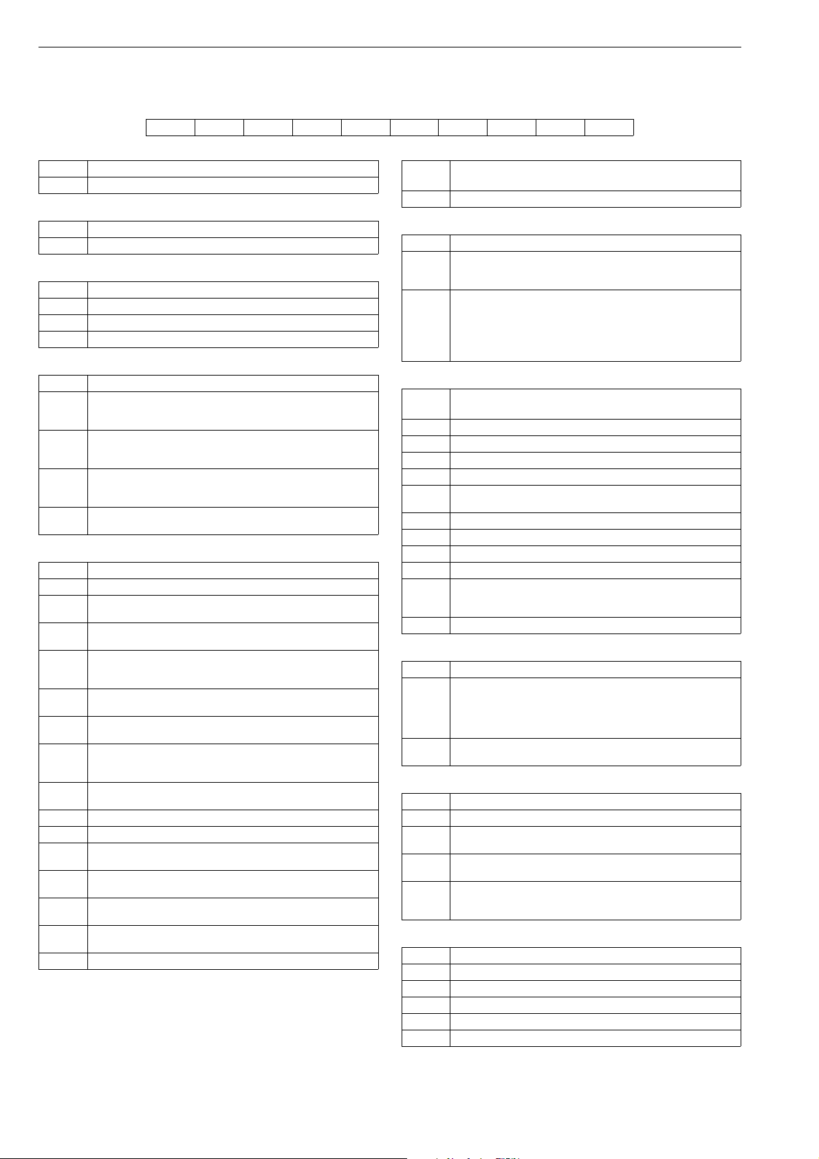
11 TYPE CODE
Pneumatic double-acting cylinder actuator, B1C
1. 2. 3. 4. 5. 6. 7. 8. 9. 10.
B1 C – S Q U 50/120 H E X
1. Product group
B1 Cylinder actuator with attachment dimensions acc. to ISO 5211
2. Series
C Double acting, pneumatic, protection class IP66.
3. Construction
- Standard construction without sign
H Manual hydraulic override
M Centre piece for manual operation (not possible, if 6. sign is U)
4. Cylinder and housing materials
Aluminium cylinder and EN 1561-GJL-200 housing, standard
-
materials, without sign. Except if sign 8. is arctic version "A"
then housing and piston always EN 1563-GJS-400-15.
Steel cylinder and EN 1561-GJL-200 housing and piston.
S
Except if sign 8. is arctic version "A" then housing and piston
always EN 1563-GJS-400-15. (Not available with size 6).
Aluminium cylinder and EN 1563-GJS-400-15 housing and
B
piston, (Not available with size 6).
When 8. sign is "A", without sign, standard material.
Steel cylinder and EN 1563-GJS-400-15 housing and piston,
X
(Not available with size 6).
5. Special construction
- Standard construction without sign
Mechanical locking device for piston movement limit on
Q
housing end. Locking with long screw to close position.
Mechanical locking device for piston movement limit on
W
cylinder end. Locking with long screw to open position.
Mechanical locking device for piston movement limit on
QW
housing and cylinder ends. Locking with long screw to close as
well as to open position.
Actuator equipped with shock absorber on cylinder end, for
Z
temperatures -20... +120 °C
Actuator equipped with shock absorber on housing end, for
N
temperatures -20... +120 °C
Actuator equipped with automatic latching device for closed
P
position. Design is made mainly for actuator locking device of
capping valve. No free motion.
Actuator equipped with manual latching device. Actuator can
T
be locked to open position allowing about 20 degrees' motion.
K Handwheel on cylinder end (sizes 9 to 25).
L Handwheel on housing end (sizes 9 to 25).
Handwheel both on cylinder end and housing end (sizes 9 to
R
25).
Handwheel on cylinder end with wormgear (sizes 32 to 75).
RK
Not used in 502, 602 and 752.
Handwheel on housing end with wormgear (sizes 32 to 75).
RL
Not used in 502, 602 and 752.
Secondary handwheel with wormgear (sizes 32 to 75).
RR
Not used in 502, 602 and 752.
Y Special
6.
U Interface according to VDI/VDE 3845, standard construction.
INTERFACE FOR ADDITIONAL DEVICES
(positioner, limit switch)
7. Actuator size
6/15 6/20 6/25 - 9/15 9/20 9/25 9/35 - 11/20 11/25 11/35 11/40 -
13/55 - 17/55 - 20/70 - 25/95 - 32/105 - 40/95 40/105 40/120 -
50/120 50/135 - 502/120 502/135 502/150 502/165 502/180
E.g. 50/120 = actuator size / shaft bore diameter.
Note special sizes (B1C 50 and 502 with oversized cylinder):
60 - max. supply pressure 8.5 bar
75 - max. supply pressure 5 bar
602 - max. supply pressure 8.5 bar
752 - max. supply pressure 5 bar
8.
- Standard construction without sign (-20° to +70 °C)
HL For temperatures -20... +120 °C and long-run option L
CL For temperatures -40... +70 °C, and long-run option L
C For temperatures -40... +70 °C
For temperatures -55... +70° C. Arctic service model. Not
A
available if 3. sign is "H" or 11. sign is "M". Size 6 not available.
F Oversized NPT connections: fast operation
F1 Larger oversized NPT connections: faster operation
L Long-run option
S Super long-run option (-20 to +70 ºC)
DU-bearings
D
- for sizes 32...502
Note: Not applicable with L, CL and HL options
Y Special
Materials of seals and bearings
(all versions ATEX II 2 G c and ATEX II 3 G c)
9. Screw material
Stainless steel (standard) for sizes 6-32.
Steel, zinc coated and passivated (standard) for sizes 40 and
-
bigger.
Steel, zinc coated and passivated for all sizes with steel
cylinder, sign 4 is S or X.
Stainless steel for sizes 40 and bigger with aluminium cylinder.
E
Stainless steel for all sizes with steel cylinder, sign 4 is S or X.
10. Non-standard operation range
- Standard, X=0, Y=90
Valve closed position is limited. When closed position is limited
X
to 30°, X = 30 (never fully closed).
Valve open position is limited. When open position is limited to
Z
70°, Z = 70 (never fully open).
Valve closed and open position are limited.
XZ
X = 30 (closed position is limited to 30°)
Z = 70 (open position is limited to 70°)
11. Special construction
6 Protection class IP66M
7 Protection class IP67/IP67M
G Oxygen service model
M K-mass fire protection
T Tropicalization
Page 19

6 BC 71 en 19
Page 20

Metso Flow Control Inc.
Europe, Vanha Porvoontie 229, P.O. Box 304, FI-01301 Vantaa, Finland. Tel. +358 20 483 150. Fax +358 20 483 151
North America, 44 Bowditch Drive, P.O. Box 8044, Shrewsbury, M A 01545, USA. Tel. +1 508 852 0200. Fax +1 508 852 8172
South America, Av. Independéncia, 2500-Iporanga, 18087-101, Sorocaba-São Paulo, Brazil. Tel. +55 15 2102 9700. Fax +55 15 2102 9748
Asia Pacic, 238B Thomson Road, #17-01 Novena Square Tower B, Singapore 307685. Tel. +65 6511 1011. Fax +65 6250 0830
China, 11/F, China Youth Plaza, No.19 North Rd of East 3rd Ring Rd, Chaoyang District, Beijing 100020, China. Tel. +86 10 6566 6600. Fax +86 10 6566 2583
Middle East, Roundabout 8, Unit AB-07, P.O. Box 17175, Jebel Ali Freezone, Dubai, United Arab Emirates. Tel. +971 4 883 6974. Fax +971 4 883 6836
www.metso.com/valves
20 6 BC 71 en
 Loading...