

Page 1
D
i
g
i
t
a
l
O
s
c
i
l
l
o
s
c
o
p
D
D
i
i
g
g
i
i
t
t
a
l
O
a
l
32
325
3232
O
s
s
c
i
l
c
l
i
l
l
52
55
o
s
c
o
s
2e-C
22
c
o
o
p
p
e
e
e
s
s
s
TTwwoo--cchhaannnneell,, 6600 MMHHzz,, EEtthheerrnneett,, CCoolloorr,
SSmmaarrtt PPeerrssiisstteenncce
TTwwoo--cchhaannnneell,, 110000 MMHHzz,, EEtthheerrnneett,, CCoolloorr,
O
O
O
p
p
p
3352
3352e----C
33523352
SSmmaarrtt PPeerrssiisstteenncce
e
r
a
t
i
n
g
I
n
s
t
r
u
c
t
i
o
n
s
e
r
a
t
i
n
g
I
n
s
t
r
u
c
e
r
a
t
i
n
g
I
n
s
t
t
r
u
c
t
i
o
n
s
i
o
n
s
,
e
,
e
Test et Mesure CHAUVIN-ARNOUX
6, avenue du Pré de Challes
F - 74940 ANNECY-LE-VIEUX
Tel. +33 (0)4.50.64.22.22
Fax +33 (0)4.50.64.22.00
GB - Maidenhead SL6 8BR
X03043A00 - Ed. 02 - 06/10
CA UK Ltd.
Waldeck House
Waldeck Road
Page 2

General instructions
Contents
General instructions Chapter I
Introduction..................................................................................... 4
Precautions and safety measures...................................................4
Symbols used..................................................................................5
Guarantee........................................................................................5
Maintenance and metrological checking.........................................5
Unpacking - Repacking ...................................................................5
Maintenance....................................................................................5
Description of instrument Chapter II
Presentation ....................................................................................6
General view....................................................................................6
Front panel (illustration)...................................................................7
Measurement terminal block (illustration)........................................7
Rear view (illustration).....................................................................8
Front panel (description)..................................................................9
Preparation for use........................................................................10
ETHERNET network......................................................................11
Oscilloscope Mode Chapter III
Keys...............................................................................................13
Display...........................................................................................17
Menus
"Vert" Vertical menu..........................24
"TRIG" Trigger menu..........................36
"Horiz" Horizontal menu..........................45
"Display" Display menu..........................50
"Measure" Measurement menu..........................53
"Memory" menu..........................58
"Util" Utilities menu..........................61
"?" Help menu..........................66
« Oscilloscope Mode with SPO » Chapter IV
Keys...............................................................................................67
Display.......................................................................................... 67
Menus
"Vert" Vertical menu..........................71
"TRIG" Trigger menu..........................71
"Horiz" Horizontal menu..........................71
"Display" Display menu..........................72
"Measure" Measurement menu..........................74
"Memory" menu..........................75
"Util" Utilities menu..........................76
"?" Help menu..........................76
“Harmonic Analysis” Mode (option) Chapter V
Installation ....................................................................................77
Keys...............................................................................................77
Display...........................................................................................77
Menus
"Vert" Vertical menu..........................80
"Horiz" Horizontal menu..........................82
"Display" Display menu..........................83
"Memory", "Util" Utilities, "?" Help menus..........................84
I - 2 Two-channel digital oscilloscopes, 60 MHz or 100 MHz
Page 3

General Instructions
Recorder Mode (option) Chapter VI
Installation .....................................................................................85
Keys...............................................................................................85
Display...........................................................................................88
Menu
"Vert" Vertical menu..........................96
"TRIG" Trigger menu..........................97
"Horiz" Horizontal menu........................102
"Display" Display menu........................103
"Measure" Measurement menu........................105
"Memory" menu........................106
"Util" Utilities menu........................109
"?" Help menu........................111
Applications Chapter VII
Calibration signal display.............................................................112
Probe compensation....................................................................112
Automatic measurements............................................................113
Cursor measurements.................................................................114
Cursor offset measurements .......................................................114
Video signal visualisation ............................................................115
Examination of a TV specific line ................................................117
« SPO » applications...................................................................118
Automatic measurements in Harmonic Analysis mode...............121
Display of slow events.................................................................124
Measurements in « Recorder » mode.........................................124
ETHERNET network....................................................................126
WEB server .................................................................................128
Technical Specifications Chapter VIII
« Oscilloscope » mode..............................................................133
Vertical deflection...................................................................133
Horizontal deflection (time base) ...........................................134
Trigger circuit .........................................................................135
Acquisition chain ....................................................................136
Display....................................................................................137
Miscellaneous ........................................................................137
« Oscilloscope mode with SPO » ............................................138
« Harmonics Analysis » mode .................................................138
« Recorder » mode ....................................................................139
Error messages ...........................................................................139
Communication interfaces...........................................................140
Remote programming..................................................................140
General characteristics Chapter IX
Environment ................................................................................141
Mains power supply.....................................................................141
EMC.............................................................................................141
Mechanical characteristics
Casing ........................................................................................141
Packing........................................................................................141
Supply Chapter X
Accessories .................................................................................142
Index
Firmware update : You may use PC software provided on the CD-ROM and consult Internet site
www.chauvin-arnoux.com. The software update involves a rebootstrrapping of the filesystem : all
Two-channel digital oscilloscopes, 60 MHz or 100 MHz I - 3
the saved files are erased and lost.
Page 4
General instructions
General Instructions
Introduction
Precautions and
safety measures
definition of
measurement
categories
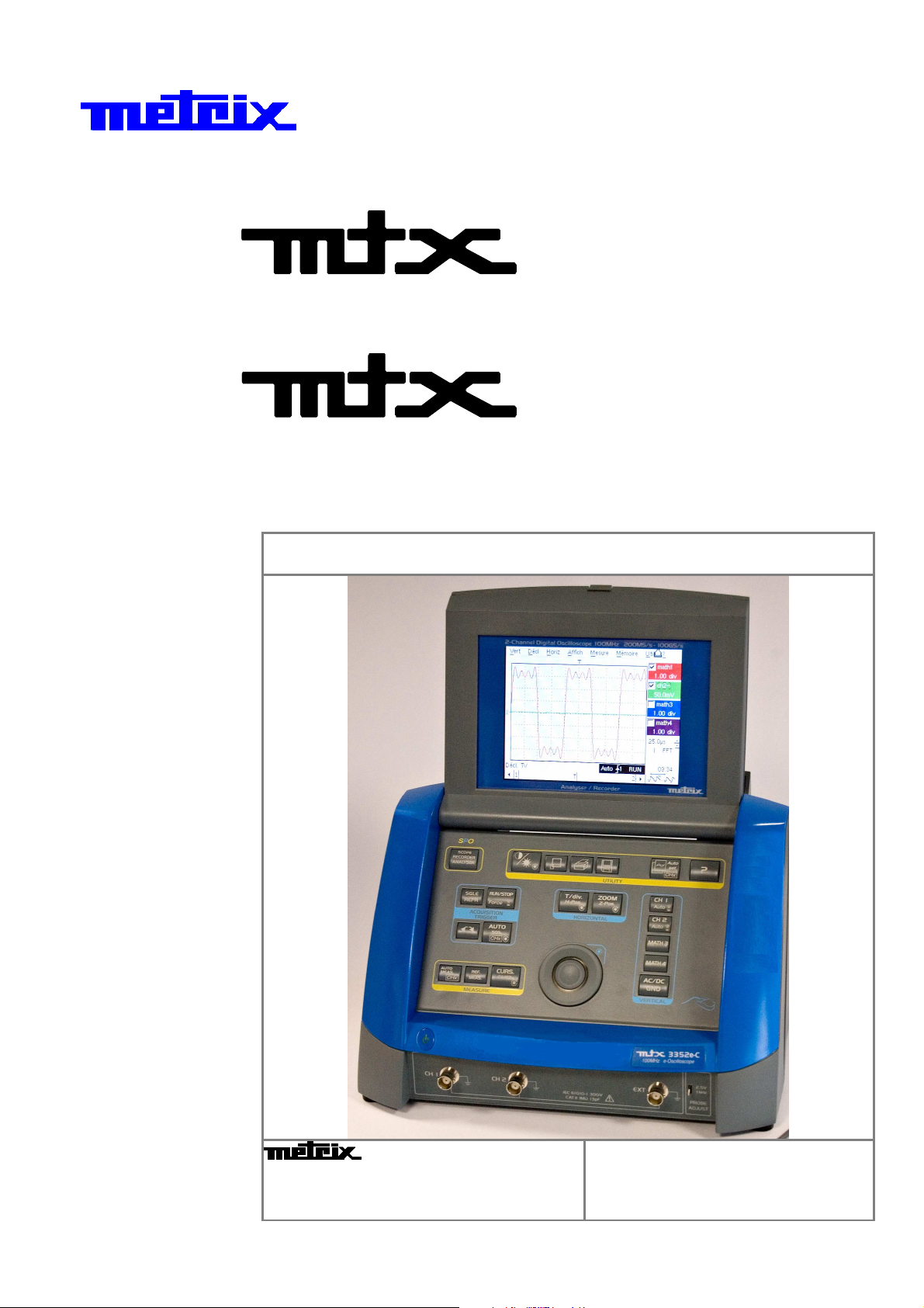
You have just acquired a two-channel digital oscilloscope with “SPO”
analog persistence display, 60 MHz or 100 MHz, ETHERNET.
It can also features a « harmonic analyser » (option) mode and a
« recorder » mode (option).
Congratulations for your choice and thank you for your trust in the quality of
our products.
This instrument conforms to safety standard NF EN 61010-1 (2001), single
insulation, relative to electronic measurement instruments.
To obtain optimum service, read these instructions with care and comply with
the precautions for use.
Failure to comply with these warnings and/or user instructions is liable to
cause damage to the equipment. This could be dangerous to the user.
•
This instrument has been designed for use:
- indoors,
- in a pollution degree 2 environment,
- at an altitude of less than 2000 m,
- at a temperature included between 0°C and 40°C
- with relative humidity of less than 80 % at up to 31°C.
•
It can be used for measurements on circuits at 300 V CAT II, relative to ground
and can be supplied by a 240 V CAT II network.
CAT I : Measurement category I is for measurements performed on circuits not
directly connected to mains.
E.g.: protected electronic circuits
CAT II : Measurement category II is for measurements performed on circuits
directly connected to the low voltage installation.
E.g.: power supply to domestic appliances and portable tools.
CAT III : Measurement category III is for measurements performed in the building
installation
E.g.: machine or industrial apparatus power supply.
CAT IV : Measurement category IV is for measurements performed at the source
of the low-voltage installation.
E.g.: energy inputs
before use
during
use
I - 4 Two-channel digital oscilloscopes, 60 MHz or 100 MHz
• Comply with environment storage conditions.
• Make sure that the three-wire phase/neutral/ground power supply cord
supplied with the unit is in suitable condition. It conforms to standard NF
EN 61010-1 (2001) and must be connected to the instrument on the one
hand, and to the network on the other (variation from 100 to 240 V
• Read carefully all the notes preceded by the symbol .
• Connect the instrument to an outlet with a ground pin.
• The instrument power supply has automatically reset electric protection
operating after the fault has been eliminated.
• Be sure not to obstruct the aeration points.
• As a safety measure, use only suitable cords and accessories supplied with
the instrument or type approved by the manufacturer.
• When the instrument is connected to the measurement circuits, never
touch an unused terminal.
AC
).
Page 5
General Instructions
General Instructions (cont’d)
Symbols
used
Guarantee
Warning: Risk of danger.
Refer to the operating manual to find out the nature of the potential hazards and
the action necessary to avoid such hazards.
Earth
This equipment is guaranteed against any material defect or manufacturing
faults, in conformity with the general conditions of sale.
During this period, the equipment may only be repaired by the manufacturer.
He reserves the right to carry out repair or replacement of all or part of the
equipment.
If the equipment is returned to the manufacturer, forward transport is at the
expense of the customer.
The guarantee does not apply in the event of:
•
unsuitable use of the equipment or by association with incompatible
equipment
•
modification of the equipment without the explicit authorization of the
manufacturer technical services
•
operation by a person not approved by the manufacturer
•
adaptation to a specific application not provided for in the equipment
definition or in the operating instructions
•
impact, fall or flooding.
According to WEEE directive 2002/96/EC
Maintenance and
metrological
checking
Unpacking and
repacking
Servicing
Before the equipment is opened, it must be disconnected from the network
supply and the measurement circuits. The operator must not become charged
with any static electricity. This could cause the destruction of internal parts.
Any adjustment, maintenance or repair of the energized equipment shall
only be undertaken by qualified personnel, after referring to the instructions
given in this document.
A qualified person is a person who is familiar with the installation, construction,
use and the hazards that exist. This person is authorized to start up and shut
down the installation and equipment in conformity with the safety rules.
Return your instrument to your distributor for any work to be done within or
outside the guarantee.
All the equipment has been checked mechanically and electrically before
shipping.
On reception, carry out a quick check to detect any damage caused by
transport. If necessary, contact our commercial department immediately and
make all legal reservations with the carrier.
In the event of reshipping, it is preferable to use the original package. Indicate
as clearly as possible, by a note attached to the equipment, the reasons for
the return.
•
Turn the instrument off.
•
Clean it with a damp cloth and soap.
•
Never use abrasive products or solvents.
•
Allow to dry before any further use.
Two-channel digital oscilloscopes, 60 MHz or 100 MHz I - 5
Page 6
Description of instrument
Smart
Harmonic
analyser
Description of instrument
Presentation
Persistence
Oscilloscope
mtx 3x52
Recorder
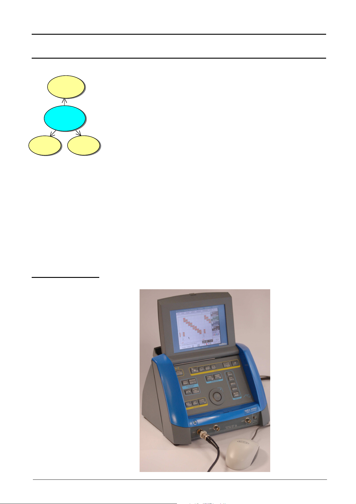
This instrument has the particularity of grouping together 3 units in 1 :
•
a Digital Oscilloscope incorporating the
FFT (Fast Fourier Transform) function and
SPO (Analog Persistence Display)
intended to analyze the signals appearing in the electronics and
electrotechnical fields
•
a Harmonic Analyser (option) mode for breaking down four signals
simultaneously while representing their fundamental and their first 31
harmonics
•
a Recorder mode (option) intended for the capture of single or slow signals.
The instrument works at a constant acquisition depth of 50,000 points.
Memory management is organized from a system of files “Windows ®” like.
A large-size colour LCD screen displays the applied signals, together with all
the adjustment parameters.
The main control functions are accessible directly from the front panel.
The adjustment parameters can be modified using the thumbwheel.
A graphic interface is similar to that of the PC and is used for:
•
using the mouse to select the functions proposed by the pull-down menus
•
acting directly on objects (traces, cursors, etc.) displayed on the screen.
The adjustment parameters can thus be modified by a variety of means.
This instrument is completed by RS232/CENTRONICS, ETHERNET and USB
to RS232 interfaces as standard.
Overall view
II - 6 Two-channel digital oscilloscopes, 60 MHz or 100 MHz
Page 7
Description of instrument
VERTICAL
HORIZONTAL
ACQUISITION
Description of instrument (cont’d)
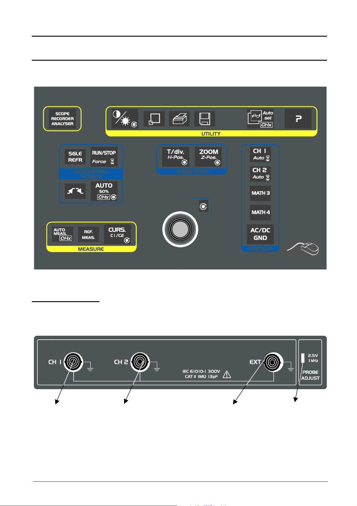
Front panel
(illustration)
SPO
TRIGGER
Measurement
terminal block
CH1 signal input CH2 signal Input EXT input Calibrator output
Two-channel digital oscilloscopes, 60 MHz or 100 MHz II - 7
Page 8

Description of instrument
Description of instrument (cont’d)
Rear panel
USB connector
USB to RS232
interface
ETHERNET RJ45
connector
SUBD 25- pin female
connector
for RS232/CENTRONICS
interfaces
6-pin MiniDin
connector
PS/2 mouse
Mains plug
II - 8 Two-channel digital oscilloscopes, 60 MHz or 100 MHz
Page 9
Description of instrument
Description of instrument (cont’d)
Front panel
(
description)
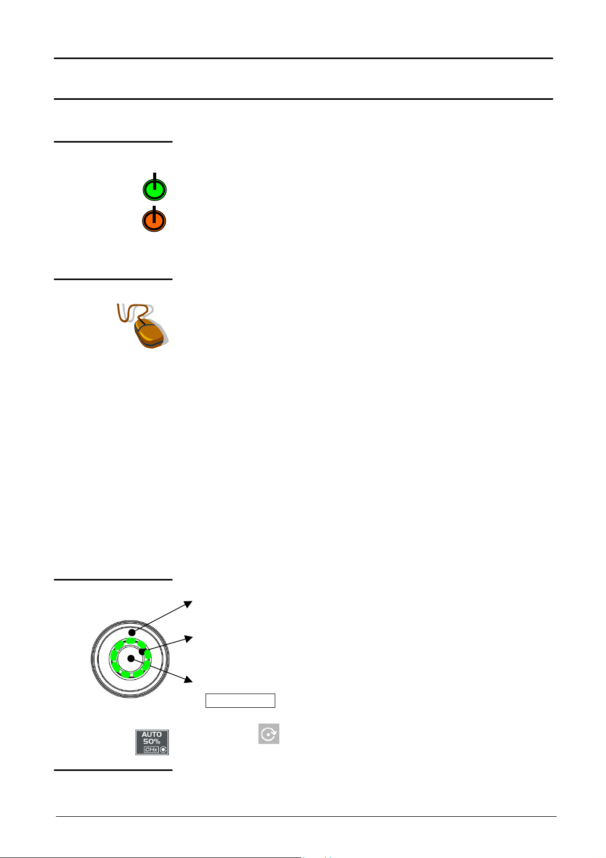
1 startup / standby
1 mouse / 2 keys
button
The main features of the equipment can be obtained from the front panel.
They can also be modified directly by the mouse or using the menu toolbar.
activates:
•
startup (green LED) when pressed briefly.
•
Setting the oscilloscope to standby (red LED) by a long press (> 3 s).
The files and the configuration are saved.
If a menu is open when the key is pressed, the backup is performed,
but no message is displayed.
connected to the back of the oscilloscope (PS/2 connector) used for:
selection of menus,
function validation,
movement of symbols appearing on LCD screen.
•
The menus appearing at the top of the screen and the submenus
selected by the mouse pointer open and are validated by the left key.
•
The menus in the trace display zone
in the control zone
in the status zone
are opened with the right mouse key.
1 rotary control
button
•
The mouse can be used for moving:
symbols appearing in the main display zone:
trigger position, cursor position, display trace reference
symbols appearing in the bargraph:
trigger position, zoomed area cursor position
Position the mouse pointer on the symbol to be moved, holding the left
key of the mouse down during the movement to the desired position.
•
Zooming in the display zone is possible using the mouse:
hold the left key down when defining the zone with the pointer (cannot
be activated in “SPO” analog persistence display
•
The outer wheel of this encoder is used for incrementing or
decrementing the selected setting (by rotation).
•
The LED comes on when adjustment is possible using the wheel. After
20 seconds without action on the wheel, the LED goes out and the
function is no longer active.
•
While the LED is on, pressing the central part of the encoder
(TOGGLE key) will toggle the adjustment of the main function to the
secondary function of the key.
The symbol appears on the keys concerned (except for the key
opposite which has no secondary function.).
21 fleeting action
keys
Two-channel digital oscilloscopes, 60 MHz or 100 MHz II - 9
giving direct access to the more basic functions.
Page 10

Description of instrument
Description of instrument (cont’d)
Preparation for use
Instructions before
startup
Error messages
Mains voltage
Fuse
Before initial startup:
•
Connect the mouse to the PS/2 connector at the back of the unit.
•
Check the power supply cord which will be connected to the back of the unit
and to the grounded mains is in good condition.
•
When on, the LED shown opposite verifies that the mains voltage is applied
to the oscilloscope.
Refer to §. Technical Specifications p. 139.
The oscilloscope power supply is designed for:
•
a mains voltage from 90 VAC to 264 VAC (use nominal range 100 VAC
and 240 VAC)
•
a frequency included between 47 Hz and 63 Hz.
The unit is protected by a fuse:
•
Fuse range: T, 2,5 A, 250 V, 5 x 20 mm
This protection fuse must only be replaced by an identical model.
Startup
LCD contrast
LCD brightness
Replacement may only be performed by qualified personnel.
Contact your closest distributor.
The pushbutton starts up the oscilloscope (the LED becomes green after
loading).
A long press (> 3 seconds) switches the equipment to standby (the LED
becomes red).
When the unit is powered up, the last memorized configuration is restored.
At initial startup, the default configuration parameters are applied.
Never disconnect the instrument from the network while the message
"System shutdown. Please wait before switch off power !" is displayed
on the screen, otherwise the current file and all the files saved
beforehand will be lost.
This key is used for adjusting the LCD contrast. Adjustment is by the
thumbwheel as long as the LED associated with it is on.
The « TOGGLE » key on the thumbwheel is used for switching from LCD
contrast adjustment to brightness adjustment (and vice versa).
II - 10 Two-channel digital oscilloscopes, 60 MHz or 100 MHz
Page 11
Description of instrument
Description of instrument (cont’d)
ETHERNET
network
General principles
of the ETHERNET
network
Addressing
ETHERNET physical
addresses
IP addresses
ETHERNET and TCP/IP (Transmission Protocol/Internet Protocol) are used to
communicate on a company's network.
Each piece of equipment under TCP/IP has a physical address (ETHERNET)
and an Internet address (IP).
A physical or ETHERNET address, stored in ROM, identifies each item of
equipment on the network. The physical address enables the equipment to
determine the source of data "packet" transmission.
The physical address is a number coded over 6 bytes represented in
hexadecimal form. Hardware manufacturers procure physical addresses and
allocate them incrementally when the product is manufactured. The physical
addresses cannot be modified.
An IP address is coded over 4 bytes, displayed in decimal format.
( Example: 132.147.250.10).
Each field may be coded between 0 and 255 and is separated by a decimal
point.
Unlike the physical address, the IP address can be modified by the user.
You must ensure that the IP address is unique on your network. If an address
is duplicated, network operation becomes random.
The IP address is made up of two parts:
•
the network identifier (Network ID) identifying a given physical network
•
the host identifier (Host ID) identifying a specific item of equipment on the
same network.
There are 5 addressing classes. Only classes A, B and C are used to identify
the equipment. See below:
Class A
0XXXXXXX XXXXXXXX XXXXXXXX XXXXXXXX
Network ID Host ID
Class B
10XXXXXX XXXXXXXX XXXXXXXX XXXXXXXX
Network ID Host ID
Class C
010XXXXX XXXXXXXX XXXXXXXX XXXXXXXX
Network ID Host ID
Two-channel digital oscilloscopes, 60 MHz or 100 MHz II - 11
Page 12

Description of instrument
Description of instrument (cont’d)
SUBNET mask and
GATEWAY
DHCP Protocol
FTP protocol
If the result of the operation ' ET LOGIQUE' between IP address of the
recipient of the message and the value of subnet mask is different from the
address of the recipient of the message, this message is sent to the gateway
which will be given the responsibility to forward it to destination.
The programming of the mask and the address of the gateway is possible on
the instrument, in the Advanced mode.
This protocol is used to automatically assign an IP address to the instrument
when it connects up to the network.
A DHCP (Dynamic Host Configuration protocol) server must be accessible on
this network (contact your network administrator to make sure that this server
is present).
FTP (File Transfer Protocol) is used in the oscilloscope for fast file transfers to
or from a PC.
To use it, open the browser on the PC and, in the URL field, type the IP
address of the instrument, preceded by "ftp:"
Example: ftp://192.168.3.1
The oscilloscope is an FTP server.
See §. Applications p. 126, 132.
HTTP protocol
LPD protocol
With this protocol, the instrument can act as a WEB server and you can access
the most frequent settings and view traces on your PC using your browser
(EXPLORER, NETSCAPE, …)
To use it, open the browser on the PC and, in the URL field, type the IP
address of the instrument, preceded by "http:"
Example: http://192.168.3.1
See §. Applications p. 128.
To be able to display the traces, you must install on your PC the Java Virtual
Machine JVM SUN 1.4.1 (or higher). This JVM can be downloaded from the
site http://java.sun.com
This protocol (Line Printer Daemon) is used by most of the printers connected
to an ETHERNET network, but also by the printing server units which handle
conversion between ETHERNET and CENTRONICS
( Example: Jet Admin) and UNIX and LINUX workstations.
An LPD server can also be installed on a PC (available as an option with
WINDOWS 2000 or XP).
In all cases, the instrument is an LPD client which has to be configured to
indicate to it the IP address of the LPD server (the workstation PC or directly
the printer) and the logical name of the printer managed by the server.
See §. Applications p. 127.
II - 12 Two-channel digital oscilloscopes, 60 MHz or 100 MHz
Page 13
Oscilloscope Mode - Keys
Selective«AUTOSET»
Oscilloscope Mode
Keys
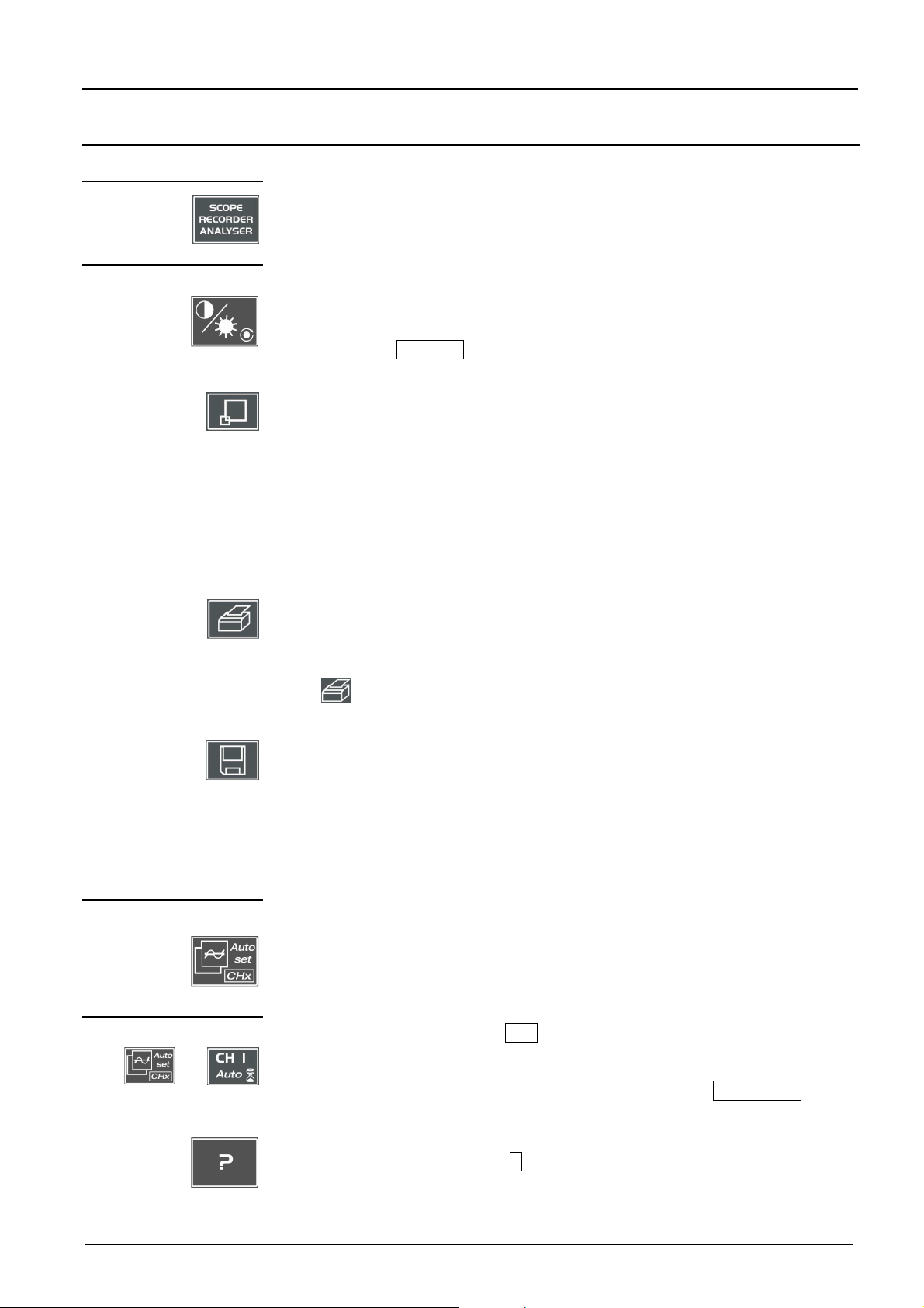
4 «UTILITY» keys
Attention
Pressing this key will configure the instrument in the following modes:
« oscilloscope »,
« harmonic analyser » (option),
« recorder » (option).
used for access to the LCD contrast adjustment using the thumbwheel.
The LED combined with the thumbwheel comes on adjustment is accessible.
The thumbwheel TOGGLE key is used for switching the key assignment from
contrast adjustment to LCD brightness.
Pressing causes switchover from normal display mode to "full screen" display
mode (and vice versa).
The screen is organized in such a way as to leave an optimum trace plotting
surface area: deletion of menu bar,
parameters of traces in time base,
bargraph.
Only permanent adjustments and measurements will remain.
In «SPO Oscilloscope » mode, this key has no action : when pressing this key the
following message is displayed : « Not possible in this mode ».
launches a hardcopy depending on the configuration produced in the « Util » and
« Hardcopy » menus.
A second press before the process end will interrupt current printing.
If printing is impossible, a « Printing error » message will be sent.
Attention
1 «AUTOSET» key
with
1 HELP key
The « » symbol is displayed in front of the display zone of the last selected
element when printing is underway.
The first press will freeze the traces on the screen. They will be displayed in plain
language as a reference to be compared with further acquisition.
A second press will erase them: the latter will then be lost.
• Traces will be saved only in the « Memory Trace Save » menu.
• The reference memory will be accompanied by a reference Nr.
In «SPO Oscilloscope » mode, this key has no action : when pressing this key the
following message is displayed : « Not possible in this mode ».
used on channels to which a signal is applied to obtain optimum automatic
adjustment (General Autoset) of coupling, vertical sensitivity, time base, slope,
framing and trigger.
The lowest frequency signal is used as a triggering source.
If no trace is detected at the inputs, the autoset will be aborted.
Simultaneously pressing with the CHx key (ch1 or ch2) will assign the
corresponding channel as trigger source, initiating an autoset which will take this
selection into consideration.
The CHx channel becomes active for adjustments by means of AC/DC/GND key.
activating or deactivating help on the keys.
Whenever a keyboard key is pressed, on-line help will be displayed for the
depressed key (except for the key ????). The functions associated with the keys will
not be started up.
On-line help can also be deactivated with the mouse (icon at top right).
The keyboard then resumes normal operation.
Two-channel digital oscilloscopes, 60 MHz or 100 MHz III - 13
Page 14
Oscilloscope Mode - Keys
Oscilloscope Mode (cont’d)
2 «ACQUISITION»
keys
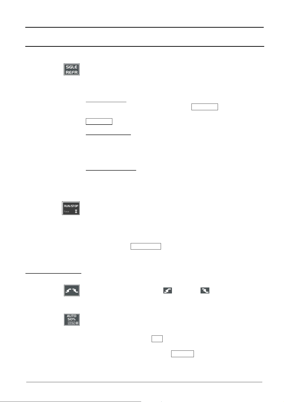
by successive pressing, select one of the following acquisition modes:
Single mode Single
Trigger mode Trig’d
Automatic mode Auto
« SINGLE » mode:
A single acquisition is triggered by pressing the RUN STOP key.
For any further acquisition, the triggering circuit must be reset by pressing the
RUN STOP key.
«TRIGGER » mode:
The screen content is only refreshed in the presence of a triggering event
related to signals appearing at the oscilloscope (ch1, ch2, ch3, ch4 or mains).
If there is no triggering event linked with the signals appearing at the inputs (or
if there is no signal at the inputs), the trace is not refreshed.
«AUTOMATIC » mode:
The screen content is refreshed even if the triggering level is not detected on
the signals appearing at the inputs.
In the presence of a triggering event, screen refreshing is managed as in the
« Triggered » mode.
2 «TRIGGER» keys
• allows starting or stopping of acquisition in « TRIGGER » and
« AUTOMATIC » mode.
• resets the triggering circuit in the «Single» mode.
• A long press forces the trigger (Force TRIG).
Acquisition is initiated according to the conditions defined by the
acquisition mode (SGLE REFR key).
Acquisition status is indicated in the status zone:
RUN = started READY = wait STOP = stopped
PRETRIG = before trigger POSTRIG = after trigger
selects the trigger slope (positive or negative ) by successive
pressing.
The slope is indicated in the status zone.
sets the trigger level to the average value of the signal (50%) without
modifying the trigger coupling.
The thumbwheel is assigned to adjusting the trigger level.
Combined pressing with the CHx key launches the same function, but
previously sets the corresponding channel as triggering source.
No functions are associated with the TOGGLE key of the thumbwheel.
Attention
III - 14 Two-channel digital oscilloscopes, 60 MHz or 100 MHz
In «SPO Oscilloscope » mode, this key has no action : when pressing this key the
following message is displayed : « Not possible in this mode ».
Page 15

Oscilloscope Mode - Keys
Oscilloscope Mode (cont’d)
3 « MEASUREMENT »
keys
activates or deactivates the display of the window for the 19 automatic
measurements of the reference trace.
Combined pressing with the CHx key displays the measurements on the
corresponding channel.
When the automatic measurement window is active, the left mouse button
is used for selecting at most 2 measurements that will appear in the status
zone at the bottom of the screen.
used for selecting (successive pressing) among the displayed traces, the
reference trace for the automatic and manual measurements.
Appears in the « Measurement » Reference menu.
activates or deactivates the cursor displays for manual measurements.
The LED combined with the thumbwheel comes on: the latter allows cursor
1 to be moved horizontally over the screen.
The thumbwheel TOGGLE key is used for moving from the cursor 1 to
cursor 2 horizontal movements and vice versa.
•
The dt measurements made (time difference between the two cursors)
and the dv measurement (voltage deviation between the two cursors) are
reported in the status zone.
•
The selected cursor position is entered into the active adjustment zone.
2 «HORIZONTAL»
keys
adjusts the time base coefficient (T/div.) by thumbwheel or the horizontal
position (H-Pos.) by the thumbwheel TOGGLE key.
The LED associated with the wheel lights up the selected adjustment is
possible with this device.
The H-Pos. adjustment modifies the horizontal (time-related) position of the
trigger point.
activates or deactivates the « Zoom » function.
The LED associated with the wheel lights up: the thumbwheel is assigned to
the horizontal zoom coefficient adjustment.
Pressing the thumbwheel TOGGLE key makes it possible to change from
the horizontal zoom coefficient setting to Z-Pos. horizontal movement in the
zoomed zone.
A zone can be zoomed by tracing a rectangle around the zone to be
enlarged using the left mouse button. The sensitivity, time base and
horizontal and vertical alignment values are recalculated automatically.
If no zones to be zoomed are selected with the mouse, a simple horizontal
zoom by default will be performed with respect to the screen center.
Two-channel digital oscilloscopes, 60 MHz or 100 MHz III - 15
Page 16
Oscilloscope Mode - Keys
Oscilloscope Mode (cont’d)
Definition :
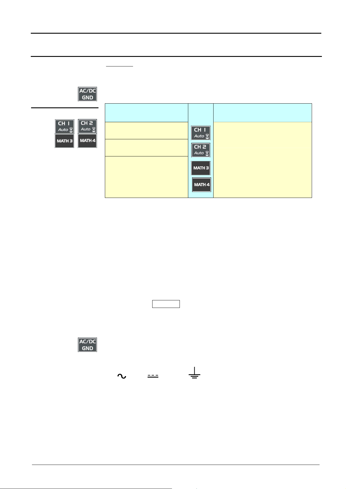
5 «VERTICAL» keys
Validated channel = Display enable (trace displayed after RUN)
Displayed channel = Validated channel and trace on screen
Selected channel = Parameter settings enabled for this channel via the
opposite key.
Before pressing one of the
four keys:
The channel concerned is not
displayed.
The channel concerned is
displayed, but not selected.
The channel concerned is
displayed and selected.
Press
on
After pressing one of the 4
keys:
The channel is displayed and is
selected. The thumbwheel is
assigned to sensitivity adjustment.
Double pressing one of those keys devalidates (erases) the concerned
signal.
In « SPO mode », the math functions are not authorized. In this case, the
MATH {3 , 4} keys validate or devalidate the M {3 , 4} memory channels.
Pressing one of these 2 keys for a long time generates a vertical autoset:
•
This modifies the sensitivity and vertical positioning of the wheel in
question.
•
It optimizes the display on the screen by activating and selecting the
channel.
Each press gives access, through the thumbweel, to the adjustment of the
sensitivity (V/div.) of the last selected channel.
By pressing the TOGGLE, you switch from the sensitivity adjustment to the
vertical position adjustment (V-Pos.).
When the LED of the thumbwheel lights on means that you may adjust with
the thumbwheel.
used for selecting, by successive pressing, input coupling « AC », « DC »
or « GND » for the last channel selected.
Coupling is indicated in the channel parameters zone:
AC : , DC : ground :
III - 16 Two-channel digital oscilloscopes, 60 MHz or 100 MHz
Page 17
Oscilloscope Mode - Display
4. Menu bar
uency of appearance (red corresponds to
Oscilloscope Mode (cont’d)
Display
in oscilloscope
mode
in SPO Persistence
mode
See chapter IV, p. 67.
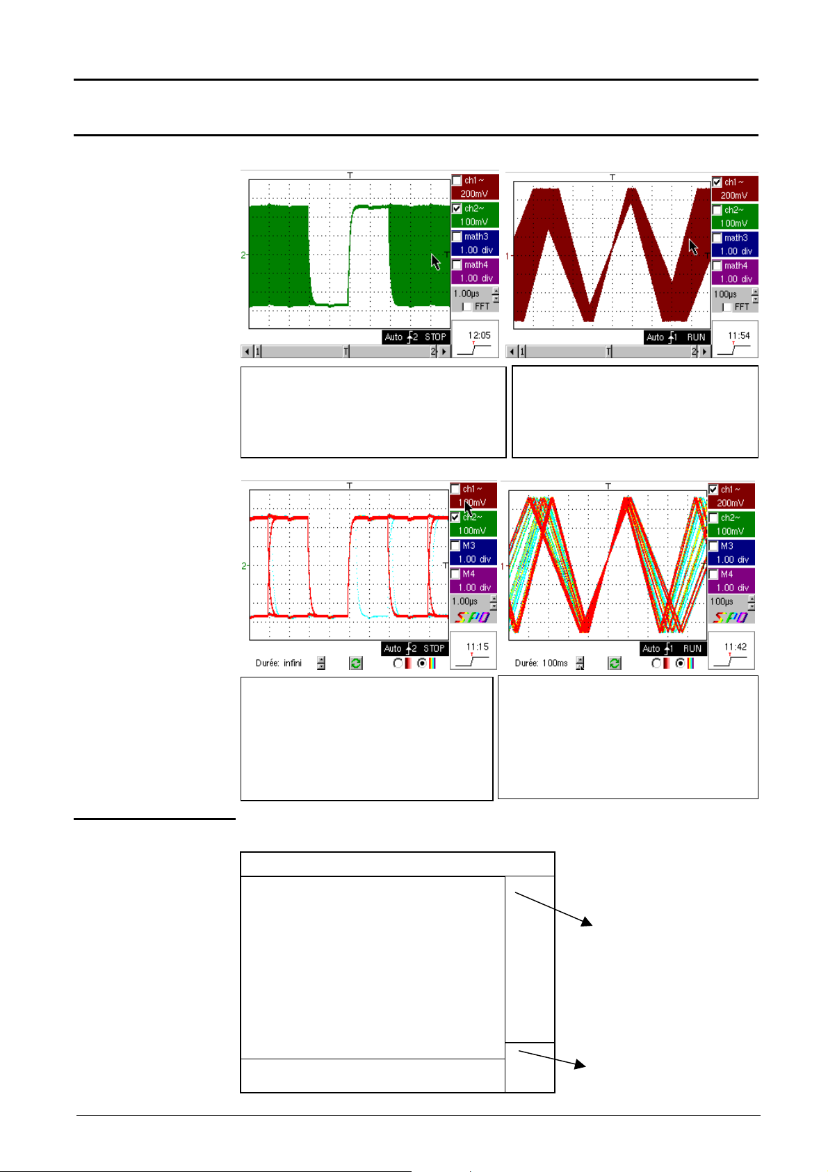
View serial bus Data in envelope mode.
In this mode, the absence of accumulation of
successive acquisitions and multi-colour display
does not show infrequent signals. All points
displayed at the same colour and intensity.
Displays a warbled triangular signal
The modulation amplitude in Envelope
mode may be seen on the screen. All
points displayed at the same colour and
intensity.
Composition
Displays serial bus Data.
In "Persistence SPO" display, successive
acquisitions are accumulated and the multicoloured view visually represents the
frequency with which points (traces) appear,
infrequent signals in "blue", and the more
frequent signals in "red".
In "Persistence SPO" view, a warbled
triangular signal is displayed: the modulation
amplitude can be viewed on the screen. The
colour of traces varies according to their
freq
high appearance frequencies and blue to
low).
The oscilloscope display is divided into 4 functional zones.
3. Display zone
zone
2. Control
Direct access
to current
adjustment
1. Status zone
Display and
adjustment of
current value
Two-channel digital oscilloscopes, 60 MHz or 100 MHz III - 17
Page 18
Oscilloscope Mode - Display
manual cursors
Movement to left of screen in
T
Oscilloscope Mode (cont’d)
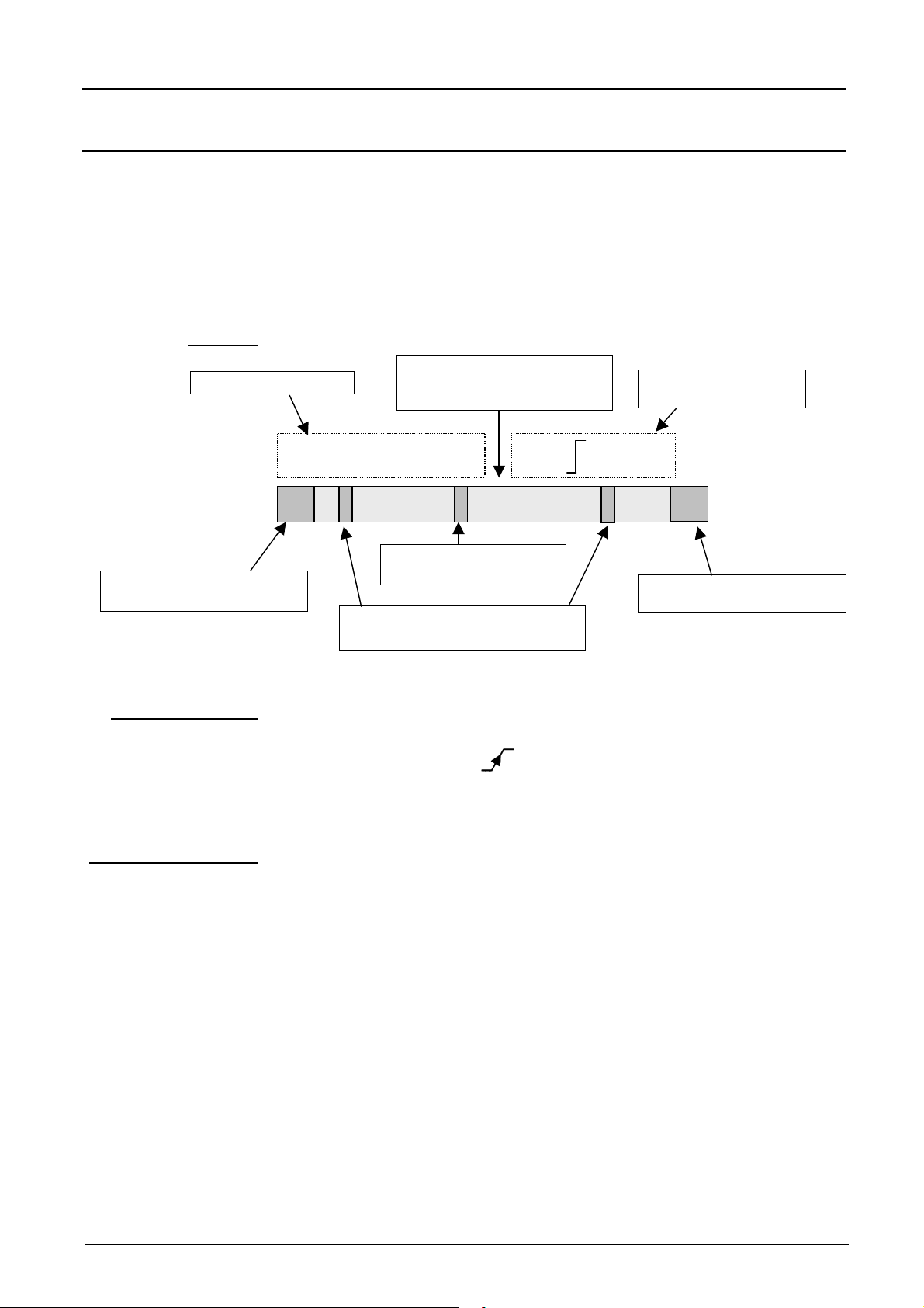
1. Status zone
Bargraph
Cursor Measurements
acquisition memory
Three types of general information appear in this zone:
•
the bargraph represents the screen position, that of the trigger and the
cursors in the acquisition memory
•
permanent instrument settings
•
measurements when the cursors are on the screen or the trigger type
(1)dt = 500µs, dv =-6,400V Trig 1 Pretrig
Each bargraph element can be moved via the mouse left button.
1
Position and movement of
Representation and
movement of screen in
acquisition memory
Position and movement
of time trigger
2
adjustments
Movement of screen to right
in acquisition memory
Permanent
Permanent settings
Cursor measurements
This zone refers to the triggering status (mode, front, source, current
status).
Example : AUTO 1 STOP
When the cursor of the mouse is placed over this information, the right
mouse button will open the "Trigger parameters" menu.
This zone refers either to:
•
horizontal (dt) and vertical (dv) difference between 2 cursors in the
case of manual measurements
(
Example : (1)dt = 500,0 µs, dv = -6,400 V)
•
phase measurement in the case of manual phase measurement (Ph)
(
Example : (1)Ph = 130.0°)
•
automatic measurements selected by the "Automatic measurements"
or "Phase measurement" menu.
(
Example : (1)F = 1.000kHz, Vpp = 15.00 V)
III - 18 Two-channel digital oscilloscopes, 60 MHz or 100 MHz
Page 19
Oscilloscope Mode - Display
Indication and adjustment of last selected
Display of ZOOM mode (Z
)
Display of the parameters
Oscilloscope Mode (cont’d)
2. Control zone
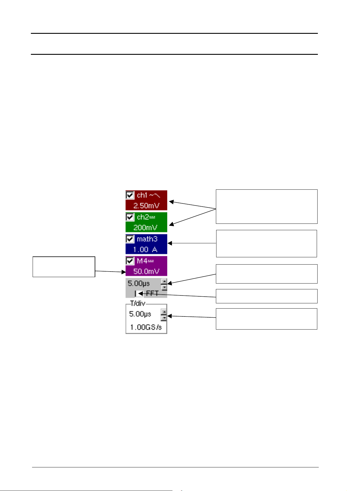
The parameters displayed in this zone are:
•
The parameters of each channel and trace: display,
sensitivity,
coupling,
bandwidth limit,
vertical scale,
function,
zoom.
•
FFT
The time base value and the loading of the signal representation domain
•
The indication and the active adjustment of the last selected element:
- trigger level, trigger type
- trigger time position
- channel offset value
- X & Y position of cursor
- time display, if no setting has been selected
- symbol of current printing ….
Display of trace parameters (in trace
color):
validity, coupling, bandwidth limit,
sensitivity
Display of ZOOM mode (Z)
Display of function parameters (in trace
color):
validity, value of division
of a memory : sensitivity,
coupling, bandwidth limit
Value of time base coefficient (s/div) in
oscilloscope mode or frequency (Hz/div)
in FFT mode
Change of signal representation domain
(FFT selection)
Contrast
25.0 %
element or otherwise time display and
trigger type
•
In SPO mode, the FFT is not available. The SPO logo is displayed.
•
The mouse left key validates the channels and the functions.
•
The «
» symbol indicates whether a channel or function has been
selected, or whether the FFT mode has been selected.
•
The adjustments of the time base (or frequency) and the value of the
active parameter can be made with the UP/DOWN button alongside the
current value display using the mouse key button.
•
After a change to the time base, the corresponding sampling frequency is
entered into the adjustment zone.
•
When the mouse is placed over the parameters of a channel or time base
value, the right mouse button opens the associated menus directly.
- Sensitivity/Coupling and Vertical scale, for channels and functions
- Source, trigger mode and RUN/STOP, for the time base
Two-channel digital oscilloscopes, 60 MHz or 100 MHz III - 19
Page 20

Oscilloscope Mode - Display
Oscilloscope Mode (cont’d)
The « Source » and « Trigger mode » menus are grouped together and
can be opened using the right mouse button by placing the pointer over
the time base zone.
3. Display zone
RUN/STOP is used for starting and stopping acquisition from this menu.
The acquisition status is indicated in the screen status.
•
The symbol « » indicates the source and selected trigger mode
•
The trigger source selectable from this menu is limited to the channels
(ch1 or ch2).
The displayed graphic elements associated with the traces in this zone
are:
•
a trigger time position indicator
•
a trigger level indicator
•
a vertical position indicator for the reference level of each trace
•
cursor position indicators linked with the curve for automatic
measurements
•
cursor position indicators linked or not linked with the curve for manual
measurements
•
the selection of a zoom zone
III - 20 Two-channel digital oscilloscopes, 60 MHz or 100 MHz
Page 21
Oscilloscope Mode - Display
7 9
8
11
10
1
3
4
5
2
1
>
v
ϕϕϕϕ
2
6
6
v
12
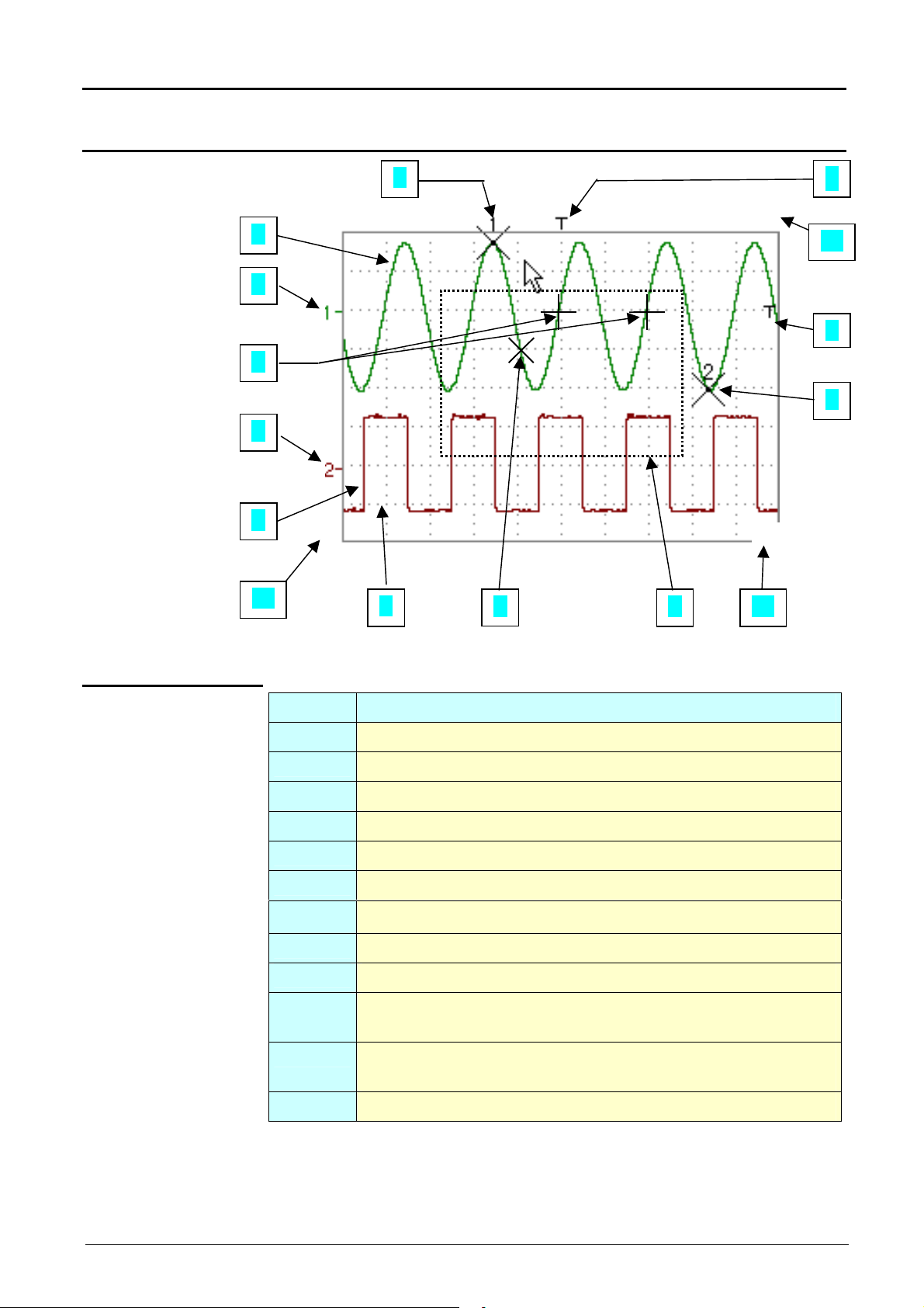
Oscilloscope Mode (cont’d)
Display elements
Definition of
display
Items Elements
1 Trace displayed
2 Indication of displayed trace reference level vertical position
Trace affichée
3 Indication of time-related position of trigger
4 Graticule division
5 Automatic measurement cursor position indicator
6 Manual measurement cursor position indicator
7 Phase measurement cursor position indicator
8 Trigger level position indicator
9 Zoom zone selection (not available in SPO)
10 Time position output indicator of trigger outside displayed
11 Trigger level position output indicator outside displayed
12 Channel level output indicator outside displayed window
window (in SPO the trigger is limited to the view zone)
window.
Two-channel digital oscilloscopes, 60 MHz or 100 MHz III - 21
Page 22

Oscilloscope Mode - Display
Oscilloscope Mode (cont’d)
Menu accessible
from display zone
How to zoom
Attention
When the mouse pointer is placed in the display zone,
the right key gives direct access to a display menu.
The « Full Screen » and « Zoom out » options are directly
accessible (see the Display menu). The same applies to
the selection of the automatic and manual measurement
reference signal (see Measurement menu).
The « » symbol indicates that the display is in the « Full Screen » or
“Full Trace” mode
(if present) and gives the reference trace for automatic and manual
measurements.
Zooming in the display zone is possible using a mouse, holding the left
mouse key down when the zone is selected by the pointer.
The zoom function is not available in SPO.
After zooming in to part of the screen, the sensitivities of the traces and
the time base are recalculated.
•
The « z » symbol appears in the parameter display of the signals and
the time base.
•
The zoomed section is represented in the bargraph.
How to move the
symbols
•
The « Zoom Out » mode (see Display menu) returns to the original
display.
•
The horizontal zoom value is adjusted to assign a calibrated value to
the horizontal scale (zoom factor: x 100 max.)
If the zoom vertical selection is greater than 6 divisions, no vertical zoom
will be performed.
All the symbols appearing in the display zone:
- trigger indicators,
- trace position indicator,
- manual cursor position indicator,
- etc …
can be moved using the left button of the mouse.
The new modified symbol value is entered into the current adjustment
display zone.
III - 22 Two-channel digital oscilloscopes, 60 MHz or 100 MHz
Page 23
Oscilloscope Mode - Display
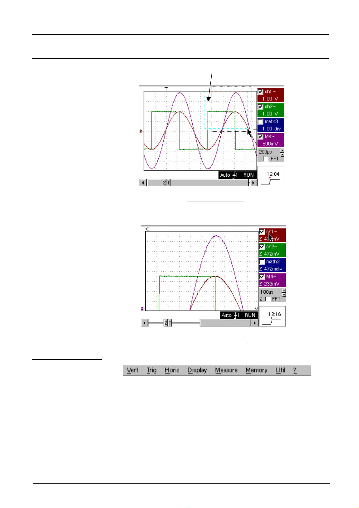
Oscilloscope Mode (Cont’d)
Example of an
expanded area
Expanded area (in blue)
Normal mode screen
Expanded mode screen
4. Menu bar
All the oscilloscope functions can be accessed by the main menus.
Two-channel digital oscilloscopes, 60 MHz or 100 MHz III - 23
Page 24
Oscilloscope Mode - The « Vertical » Menu
Oscilloscope Mode (cont’d)
The « VERT » Menu
15MHz
(∗)
Only available in advanced mode
if the SPO mode is not selected.
See §. Description, page 65.
III - 24 Two-channel digital oscilloscopes, 60 MHz or 100 MHz
Page 25

Oscilloscope Mode - The « Vertical » Menu
Modifies the sensitivity of the channel using the scroll bar and the left mouse
Oscilloscope Mode (cont’d)
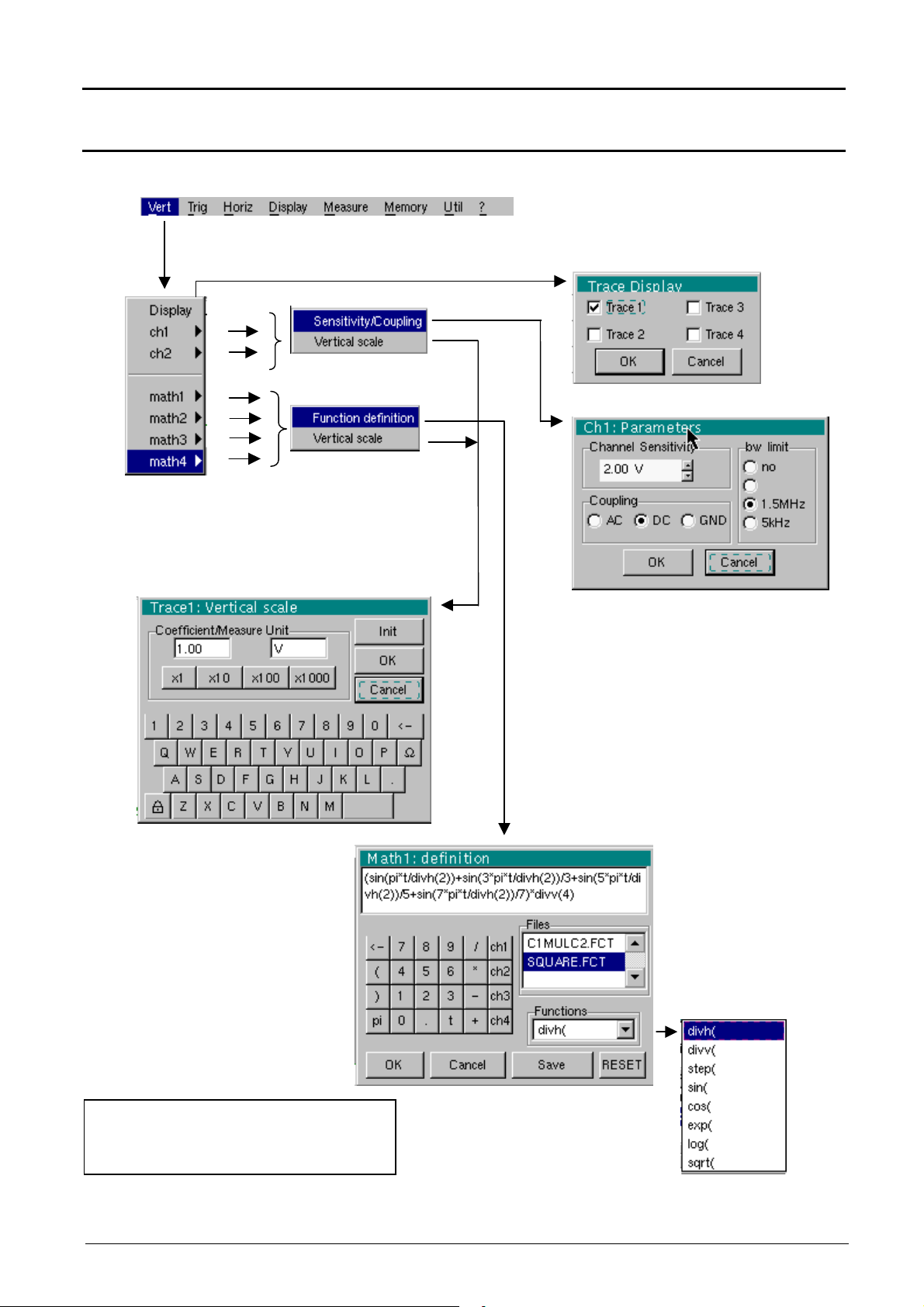
Display
ch1 ch2
Sensitivity/Coupling
Channel Sensitivity
Coupling
opens the « Trace display » menu for validating or devalidating the traces.
Validation of selections by « OK ». Exit from menu without modification by
« Cancel ».
The «
» symbol in front of a trace indicates its validation.
The traces can be validated or devalidated from the command zone using
the left mouse button.
modifies independently the ch1 and ch2 parameters and modifies the
selected trace vertical scale.
modifies the selected channel parameters.
button, adjustable by sequence: from 2.5 mV to 100 V/div.
Sensitivity is entered into the channel parameter display zone. It takes the
« Vertical scale » menu parameters into consideration.
Modification of the AC - DC - GND coupling
AC : blocks the DC component of the input signal and attenuates the signals
lower than 10 Hz.
DC : transmits the DC and AC components of the input signal.
GND : the equipment connects internally the selected channel input to a
0 V reference level.
The « » symbol indicates the selected coupling. Coupling is reported in
the modified channel parameter display zone.
BW limit
This menu can also be called by clicking with the right mouse key in the
Vertical scale
Coefficient assigns a multiplication coefficient to the selected channel sensitivity.
Limits the bandwidth of the channel and its trigger circuit to reduce display
noise and false triggering.
The bandwidth of each channel can be limited to 5 kHz, 1.5 MHz or
15 MHz. The bandwidth limit of a channel is indicated in the control area by
following symbols :
Validation of selections by « OK ». Exit from menu without modification by
« Cancel ».
desired channel parameter display zone.
defines the vertical scale of the channel selected from the current
adjustments. Reading and direct measurements of the analyzed
magnitude and its unit are obtained.
The modification is made using the mouse with the table of usable
numbers, having selected the « Coefficient » zone.
The key deletes the previous value of the cursor in this zone.
15 MHz
1.5 MHz
5 kHz
The predefined values (x1, x10, x100, x1000) correspond to standard
probe coefficients and can be assigned directly.
The sensitivity value indicated in the channel parameter display will be
modified according to this coefficient.
Two-channel digital oscilloscopes, 60 MHz or 100 MHz III - 25
Page 26
Oscilloscope Mode - The « Vertical » Menu
∗)
Oscilloscope Mode (cont’d)
Measure unit
math1 math2
math3 math4
Function definition
modifies the vertical scale unit of the selected channel.
The modification is carried out by the mouse using the table of characters that
can be used after selecting the “measure unit” zone.
The key is used for deleting the character leading the cursor in this zone.
The "Padlock " key can be used to switch between upper-case and lowercase characters.
The vertical scale unit will be entered into the modified channel parameter
display.
re-initializes the multiplication coefficient at 1.00 and returns to a measure unit
Init
in Volt.
Validation of selections by « OK ». Exit from menu without modification by
« Cancel ».
This menu can be called by dialogue with the right mouse button in the display
of the desired channel parameters (ch1 or ch2).
defines for each trace a mathematical function and the vertical scale.
Menus present only in Advanced mode (see menu « Util », p. 61).
defines the mathematical function to be assigned to the selected trace.
The function is defined using the usable characters table, and associating the
ch1 and ch2 traces.
•
The mathematical function can be defined on 2 lines.
•
mathx cannot be used in the definition of a function.
Functions
The key deletes the character preceding the cursor in the window.
8 predefined mathematical functions can be linked to the traces :
divh(
divv(
step(
sin(
(
divh(1) is equivalent to 5000 samples (counts) = 1 horizontal div.
Validation of the selections by "OK". Exit from the menu without modification by
"Cancel".
If … then …
... the dynamic calculation of the
vertical scale is impossible
... the dynamic calculation of the
vertical scale is possible
CHx + CHy Sensitivity and measuring unit used on CHx
CHx - CHy Sensitivity and measuring unit used on CHx
In each cases, the measuring unit can be re-defined and a coefficient can be applied
to the measurement results (refer to §. Vertical scale).
("horizontal division")
("vertical division")
("step") using "t" (∗)
("sine")
t = abscissa of the sample in the 50,000-sample acquisition memory.
Particular cases : Value of the measuring unit
cos(
exp(
log(
sqrt(
(« cosine »)
(« exponential »)
(« logarithmic »)
(« square root »)
... a message indicates that the
measuring unit on this function will
be vertical division (div).
... it takes into account of the
sensitivities of the channel sources.
III - 26 Two-channel digital oscilloscopes, 60 MHz or 100 MHz
Page 27
Oscilloscope Mode - The « Vertical » Menu
Oscilloscope Mode (cont’d)
Examples
Use of predefined
mathematical
functions
• Predefined divv() function used on its own: math3 = divv(3).
The trace is equal to 3 vertical divisions.
divv(3) = 3 x 32000 LSB = 3 vertical divisions
•
Predefined step() function associated with a trace:
- math2 = ch1*step(t-divh(4))
math2 is at 0 vertical divisions as long as t (time is less than four
horizontal divisions).
math2 is equal to ch1 when t (time) becomes greater than four
horizontal divisions.
- math2 = ch1*step(divh(4)-t)
math2 is equal to ch1 as long as t (time) is less than four divisions.
math2 is at 0 vertical divisions when t (time) becomes greater than
four horizontal divisions.
Two-channel digital oscilloscopes, 60 MHz or 100 MHz III - 27
Page 28
Oscilloscope Mode - The « Vertical » Menu
Oscilloscope Mode (cont’d)
Example 1
Appropriate use of the
operators for display
optimisation
Traces ch1 and ch2 are optimised on 6 vertical divisions.
Vhigh ch1 = 3 vertical divisions => 3 x 32000 LSBs = 96000 LSBs
Vhigh ch2 = 3 vertical divisions => 3 x 32000 LSBs = 96000 LSBs
Note : 1 vertical division = 32000 LSBs
Addition of two traces - math3 = ch1+ch2
Vhigh
Sensitivity: Ch1 = Ch2 = 1 V/div
Vpp: Ch1 = Ch2 = 6 V
Vhigh: Ch1 = Ch2 = 3 V
In this case of trace addition, you can observe a high and low
overshoot, division by two is necessary to optimise display of the
result.
Vhigh math3 = 6 vertical divisions = 6 x 32000 LSBs =128000 LSBs
> (4 vertical divisions)
- math3 = (ch1 + ch2) / 2
Vertical scale math3 = 1.00 V
Vpp math3 = 6.00 V
Vhaut math3 = 3.00 V
Division by two adjusts the addition to the dynamics of the screen
Vhigh math3 = 3 vertical divisions = 3 x 32000 LSBs
Note: The results of the automatic Vhigh and Vpp by math 3 must be
multiplied by two to be correct.
III - 28 Two-channel digital oscilloscopes, 60 MHz or 100 MHz
Page 29

Oscilloscope Mode - The « Vertical » Menu
Oscilloscope Mode (cont’d)
For immediate interpretation of the results, configure the "Vertical scale"
menu of mathx (see §. Opening from math1, math2, math3, math4 p. 35).
In our example:
• The sum of ch1 + ch2 is the sum of two values in volts, so the
result is expressed in volts.
• The sum of ch1 + ch2 must be divided by 2, so the coefficient of
math3 can be replaced with 2 to obtain the automatic measurement
results of math3 immediately.
• Then select math3 as the reference for the automatic and manual
measurements (see "MEASUREMENT" menu, p. 53).
• Then display the table of 18 measurements made on the math3 trace
(see "MEASUREMENT" menu, p. 53).
The measurements displayed are the exact result of the addition of the
two traces ch1 + ch2 in the correct unit (Volts).
Vhigh
Vertical scale math3 = 2.00 V
Vpp math3 =12.00 V
Vhigh math3 = 6.00 V
Two-channel digital oscilloscopes, 60 MHz or 100 MHz III - 29
Page 30
Oscilloscope Mode - The « Vertical » Menu
Oscilloscope Mode (cont’d)
Example 2
Sensitivity: Ch1 = Ch2 = 5 V/div
Vpp: Ch1 = Ch2 = 10 V
Vhigh: Ch1 = Ch2 = 5 V
Vhigh ch1 = 1 vertical division => 1 x 32000 LSB = 32000 LSBs
Vhigh ch2 = 1 vertical division => 1 x 32000 LSB = 32000 LSBs
Multiplication of two
traces
- math3 = ch1*ch2
As for the addition of traces, we can observe a much more significant high
and low overshoot.
Vhigh math3 = ch1 x ch2 = 1 vertical division x 1 vertical division
= 32000 LSB x 32000 LSB = 1024 106 LSB
> (4 vertical divisions = 128000 LSBs)
The function divv (vertical division) is necessary to optimise the display.
- math3 = (ch1*ch2)/divv(1)
Divv(1) can be used to divide by 32,000 (1 vertical division = 32,000 LSBs):
the result of the multiplication is translated into divisions on the screen.
Note: If Vpp of ch1 and ch2 had been 8 vertical divisions, the multiplication
would have had to be divided by divv(4).
When mathematical functions associated with traces are used, the
dynamics of the result obtained must be verified.
Correction of the result of the operations by mathematical functions (divv(),
divvh(), / …) is recommended to optimise the screen display.
III - 30 Two-channel digital oscilloscopes, 60 MHz or 100 MHz
Page 31

Oscilloscope Mode - The « Vertical » Menu
Oscilloscope Mode (cont’d)
For immediate interpretation of the results, configure the "Vertical scale"
menu of mathx (see §. Opening from math1, math2, math3, math4 p. 35).
In our example:
• The multiplication of ch1 by ch2 is the multiplication of Volts by
Volts, so the result is in square volts.
• div of the measurement unit of math3 can be replaced by V2 (Volts).
• A vertical division represents 5 V x 5 V = 25 V2 (vertical sensitivity
of ch1 x vertical sensitivity of ch2).
• The coefficient of math3 can be replaced by 25 to obtain the result of
the automatic math3 measurements immediately.
• Then select math3 as the reference for the automatic and manual
measurements (see "MEASUREMENT" menu).
• Then display the table of 19 measurements made on the math3 trace
(see "MEASUREMENT" menu).
The measurements displayed are the result of the multiplication of the two
traces ch1 and ch2 in the correct unit (V2).
Vertical scale math3 = 25 V2
Vpp math3 =25 V2
Two-channel digital oscilloscopes, 60 MHz or 100 MHz III - 31
Page 32

Oscilloscope Mode - The « Vertical » Menu
The period equal to 10,000 samples (2 horizontal divisions) depends on the
Oscilloscope Mode (cont’d)
Example 3
Association
of predefined
functions
- math3 = divv(3)*sin (2*pi*t/10000).
The trace obtained is a sine wave produced using the predefined sin
(sine) function, according to its mathematical definition (2 x π x
Frequency).
The amplitude is 6 divisions (divv(3) x 2 = 3 x 32000 LSBs x 2).
time base.
•
Same trace produced with the predefined divh function:
math3 = divv(3)*sin(2*pi*t/divh(2))
In this example, divh(2) is equivalent to 10,000 samples.
Note: 1 horizontal division = 5,000 samples
The period divh(2) is equal to 10,000 samples (2 horizontal divisions)
depends on the time base.
• Production of a sine wave by the predefined cos (cosinus) function:
math3 = divv(3)*cos(2*pi*t/divh(2))
The trace obtained with the predefined cos() function is offset by 90°.
III - 32 Two-channel digital oscilloscopes, 60 MHz or 100 MHz
Page 33

Oscilloscope Mode - The « Vertical » Menu
Oscilloscope Mode (cont’d)
Production of an
attenuated sine
wave using
predefined
math1 = sin (pi*t/divh(1))*exp(-t/divh(6))*divv(4)
functions
sin (pi*t/divh(1)) can be used to modify the number of periods.
exp (-t/divh(6)) can be used to modify the level of attenuation.
exp (-t) represents:
exp(-5000) when you reach the first horizontal division.
exp(-50,000) when you reach the tenth horizontal division.
Two-channel digital oscilloscopes, 60 MHz or 100 MHz III - 33
Page 34

Oscilloscope Mode - The « Vertical » Menu
Oscilloscope Mode (cont’d)
Files
C1MULC2 .FCT
function
contains the list of the functions (.FCT) saved by the user, along with two
predefined files.
By selecting the name of the function with the left mouse button (function
name in blue), you can transfer the definition of the function into the 2
lines provided for that purpose.
The scroll bar can be used to scroll through the list of memorized
functions.
The function can be modified with the table of usable characters,
associating the ch1 and ch2 traces.
This menu also contains two predefined functions.
C1MULC2.FCT : ch1*ch2/divv(4) is used to calculate the product of 2
traces with rescaling so that the result fits the screen.
The factor divv(4) is used to optimize the display as long as the source
signals have sufficient dynamics (> 5 divisions) and no overshooting.
The MATH functions cannot be accessed in SPO mode.
math3 = ch1*ch2/divv(4) = C1MULC2.FCT
SQUARE.FCT
function
III - 34 Two-channel digital oscilloscopes, 60 MHz or 100 MHz
This is the definition of a square signal using the first 4 harmonics of a
Fourier series development.
math3 = SQUARE.FCT
math3 = (sin(pi*t/divh(2)) + sin(3*pi*t/divh(2))/3 + sin(5*pi*t/divh(2))/5
+ sin(7*pi*t/divh(2))/7)*divv(4)
Page 35

Oscilloscope Mode - The « Vertical » Menu
Oscilloscope Mode (cont’d)
Save
backs up the definition of the function by the “File Copy “ menu. Extension
«.FCT».
Reset
Vertical scale defines the vertical scale of the selected trace.
completely resets the function definition.
After assigning a function to the ch1 (math1) or ch2 (math2) channels,
« mathx » appears in the corresponding channel parameter display zone.
Calling this menu from math1, math2 is identical to calling ch1, ch2 as long
as the functions have not been defined.
Once a function has
been defined on
mathx, opening the
‘vertical scale’ menu
from math
Coefficient
Measure unit
modifies the value of a selected trace division (div).
Modification is by using the mouse with the table of numbers that can be
used after selecting the coefficient zone.
The key deletes the character preceding the cursor in this zone.
Predefined values (x1, x10, x100, x1000) correspond to standard probe
coefficients and can be assigned directly.
The value of a division will be entered into the display of the modified trace
parameters.
modifies the unit of the vertical scale (div) of the selected trace.
Modification is performed by means of the mouse with the table of
characters that can be used after selecting the management unit zone.
The key deletes the value preceding the cursor in this zone.
The "Padlock " key can be used to switch between upper-case and
lower-case characters.
The vertical scale unit will be entered into the modified trace parameter
display (3 characters max).
Init
re-initializes the coefficient at 1,000 (x1) and returns to a unit of measure in
V.
Validation of selections by « OK ». Exit from menu without modification by
« Cancel ».
The « Vertical scale » menu can also be called up by clicking with the right
mouse key in the trace parameter display math3 or math4 as desired.
Two-channel digital oscilloscopes, 60 MHz or 100 MHz III - 35
Page 36

Oscilloscope Mode - The « Trigger » Menu
Oscilloscope Mode (cont’d)
The « TRIG » Menu
III - 36 Two-channel digital oscilloscopes, 60 MHz or 100 MHz
Page 37

Oscilloscope Mode - The « Trigger » Menu
Oscilloscope Mode (cont’d)
Definition
This range of portable oscilloscopes is equipped with "advanced triggers".
•
The "Main" tab can be used to choose and parameterize the main trigger
source.
•
The "Delay" and "Count" trigger modes require parameterization of a
second "auxiliary" trigger source. The auxiliary source may be the same as
the main source.
The trigger choice is validated by exiting from the menu.
If …
… the user exits from the "Main" tab, … "Main" triggering is used.
… the user exits from the"Pulse" tab, … "Pulse" triggering is used.
etc.
•
There is only one Holdoff, although it can be programmed from the "Main",
"Delay", "Count", “TV” and “Line” tabs.
When you use "Delay" or "Count", the Holdoff applies to the auxiliary source,
i.e. the source of the count pulses or delay trigger pulses.
In the other cases, Holdoff applies to the main trigger source.
•
Each trigger source has its own specific attributes: Coupling, Level, Edge,
Noise Reject, Filter.
then …
etc.
Parameters
Main
Source
Selection of the "Trigger Parameters"
Trigger on edge
selects channel as main trigger source
Trigger source : 1, 2, 3, 4 or L (line)
Trigger Source : 1, 2 or S (line)
You can also
choose the
trigger channel
by doublepointing with
the mouse in
the time base
display area.
Two-channel digital oscilloscopes, 60 MHz or 100 MHz III - 37
Page 38

Oscilloscope Mode - The « Trigger » Menu
AC
Oscilloscope Mode (cont’d)
Coupling Selection of the filter for the main trigger source:
AC AC coupling (10 Hz to 200 MHz):
blocks the DC component of the signal
DC DC coupling (0 to 200 MHz):
allows the entire signal through
LF Reject Rejection of source signal frequencies < 10 kHz:
facilitates observation of signals with a DC component or an
unwanted low frequency
Edge
Level
HF Reject Rejection of source signal frequencies > 10 kHz:
facilitates observation of signals with high-frequency noise.
Selection of the trigger gradient:
+ ascending trigger edge
- descending trigger edge
The selected trigger edge is indicated the status area.
454mV Adjustment of the trigger level with the mouse on the scroll bar.
Clicking with right mouse key in this field displays a virtual numeric
keypad which can be used to directly input the value.
The trigger level is entered into the current value display area after
modification. Fine adjustment is possible.
Noise reject
Holdoff
Example
Selection of the main
trigger source
Selection of the
trigger level
No hysteresis ≈ 0.5 div.
Yes introduces a hysteresis of ≈ 1.5 div.
40.0ns allows:
•
disabling of the trigger for a predefined period
•
stabilization of the trigger on pulse trains.
Double-tapping in this field displays a virtual numeric keypad which can be used
to directly input the value.
Clicking with right mouse key in this field displays a virtual numeric
keypad which can be used to directly input the value.
Signal injected on CH1: a train of three 6 VDC pulses at a frequency of 20 kHz
with a 500 mVDC component, separated by 500 µs.
Selection of the
noise rejection
Selection of the
trigger slope
III - 38 Two-channel digital oscilloscopes, 60 MHz or 100 MHz
Selection of the trigger channel
coupling
- DC - Rejet BF - Rejet HF
Selection of the
HOLDOFF value
from 40 ns to 10.5 s
Page 39

Oscilloscope Mode - The « Trigger » Menu
Oscilloscope Mode (cont’d)
The trigger is set with channel 1 as the source and a level of 2.04 V, on an
ascending edge.
The Holdoff stabilizes the signal by disabling the trigger for 108 µs.
The DC coupling of the trigger lets the whole signal through.
In this example, the signal does not include noise, so the noise rejection option is
not necessary.
The DC coupling of ch1 shows the DC component of the signal.
Pulse
Selection of pulse-width trigger. In all cases, the effective trigger occurs on the
pulse trailing edge.
< triggers on a pulse if its width is less than the value set
= triggers on a pulse if its width is equal to the value set
> triggers on a pulse if its width is greater than the value set
Note : The pulse width is defined by the crossing of the signal with the vertical
trigger level.
975 µs Adjustment with the mouse using the time setting scroll bar
Clicking with right mouse key in this field displays a virtual numeric
keypad which can be used to directly input the value.
The choice of the (rising) or (falling) edge in the "Main" tab defines the
limits of the analysis:
• edge defines a positive pulse between or
• edge defines a negative pulse between or
Example
Current main
source recall
Pulse polarity
Pulse width :
< = >
Signal injected on CH1: a train of three 6 VDC pulses at a frequency of 20 kHz
separated by 500 µs
Reference pulse width selection
from 20 ns to 10,5 s
The trigger parameters in the main menu are active (Source, Level, Edge, etc.).
The oscilloscope is triggered when the signal's pulse width is equal to the
specified pulse width (25.0 µs + tolerance).
Positive pulse : the width measurement is triggered on the pulse rising edge and
the trigger is effective on the falling edge, if the pulse width respects the chosen
comparison criterion (= 25.0 µs in that case).
Two-channel digital oscilloscopes, 60 MHz or 100 MHz III - 39
Page 40

Oscilloscope Mode - The « Trigger » Menu
Oscilloscope Mode (cont’d)
Auxiliary source
Delay
Trigger delay
Holdoff
Coupling
Selection of edge trigger with delay
The delay is triggered by the auxiliary source.
Effective triggering occurs after the end of the delay on the next event from the
main source.
12.4µs Adjustment with the mouse using the setting scroll bar to choose the
required delay value.
Clicking with right mouse key in this field displays a virtual numeric
keypad which can be used to directly input the value.
40ns Adjustment with the mouse using the setting scroll bar, allows
disabling of the trigger for a predefined period and, among other
things, stabilization of the trigger on pulse trains.
Clicking with right mouse key in this field displays a virtual numeric
keypad which can be used to directly input the value.
selects the channel as the main trigger source
selects the filter for the auxiliary trigger source:
AC AC coupling (10 Hz to 200 MHz):
blocks the DC component of the signal
Level
Edge
Noise reject
DC DC coupling (0 to 200 MHz):
allows the entire signal through
LF Reject Rejection of source signal frequencies < 10 kHz:
facilitates observation of signals with a DC
component or an unwanted low frequency
HF Reject Rejection of source signal frequencies > 10 kHz:
facilitates observation of signals with high-frequency noise
454mV Adjustment of the trigger level with the mouse on the scroll bar.
Clicking with right mouse key in this field displays a virtual numeric
keypad which can be used to directly input the value.
selects the edge for the auxiliary trigger source:
+ ascending trigger edge
- descending trigger edge
No hysteresis ≈ 0.5 div.
Yes introduces a hysteresis of ≈ 1.5 div.
III - 40 Two-channel digital oscilloscopes, 60 MHz or 100 MHz
Page 41

Oscilloscope Mode - The « Trigger » Menu
Selection of the auxiliary
Oscilloscope Mode (cont’d)
Example
Selection of the trigger
delay applied to the
main source
from 20 ns to 10,5 s
Selection of the
auxiliary source
source trigger level
Selection of the
auxiliary source
noise rejection
Signal injected on CH1: a train of three 6 VDC pulses at a frequency of 20 kHz
separated by 500 µs.
Selection of the auxiliary source coupling
Number of events
Auxiliary source
Count
Holdoff
The trigger is active after the end of the delay (35.2 µs) on the first ascending
edge.
The Holdoff stabilizes the signal by disabling the trigger for 108 µs.
Selects the edge trigger with counting of events.
The count is triggered by the auxiliary source. The main source serves as a
clock for the count.
Effective triggering occurs after the end of the count on the next event from the
main source.
4 Adjustment with the mouse using the setting scroll bar to choose the
Clicking with right mouse key in this field displays a virtual numeric
keypad which can be used to directly input the value.
40.0ns Adjustment with the mouse using the setting scroll bar, disabling of
the trigger for a predefined period and, among other things,
stabilization of the trigger on pulse trains.
Clicking with right mouse key in this field displays a virtual numeric
keypad which can be used to directly input the value.
selects a channel as the main trigger source
number of events required.
Two-channel digital oscilloscopes, 60 MHz or 100 MHz III - 41
Coupling
Selection of the filter for the auxiliary trigger source:
AC AC coupling (10 Hz to 200 MHz):
blocks the DC component of the signal
DC DC coupling (0 to 200 MHz):
allows the entire signal through
LF Reject Rejection of source signal frequencies < 10 kHz
facilitates observation of signals with a DC component
HF Reject Rejection of source signal frequencies > 10 kHz
facilitates observation of signals with high-frequency noise
Page 42

Oscilloscope Mode - The « Trigger » Menu
Oscilloscope Mode (cont’d)
Edge
Level
Noise reject
Example
Selection of the number
of events on the main
source : from 2 to 16,384
Selection of the trigger edge of the auxiliary source
+ trigger on ascending edge
- trigger on descending edge
454mV Adjustment of the trigger level of the auxiliary source with the
mouse on the scroll bar.
Clicking with right mouse key in this field displays a virtual numeric
keypad which can be used to directly input the value.
No: hysteresis ≈ 0.5 div.
Yes: introduces a hysteresis of ≈ 1.5 div.
Signal injected on CH1: a train of five 6 VDC pulses at a frequency of 20 kHz
separated by 500 µs.
The trigger is set on the descending edge.
The first edge activates the trigger. It is not included in the count.
The trigger is triggered on the third descending edge of the pulse train.
The Holdoff stabilizes the signal by disabling the trigger for 232 µs.
III - 42 Two-channel digital oscilloscopes, 60 MHz or 100 MHz
Page 43
Oscilloscope Mode - The « Trigger » Menu
Oscilloscope Mode (cont’d)
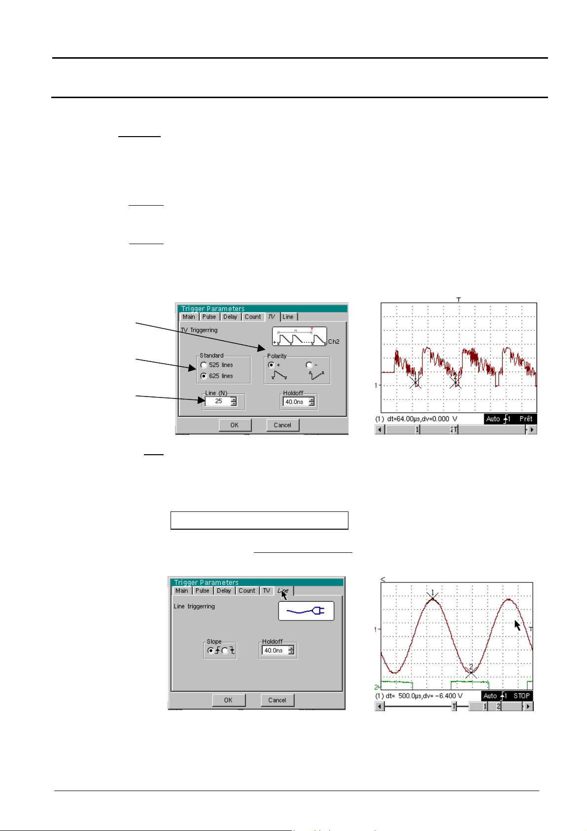
TV Trigger on a TV line
Standard
Polarity
Holdoff
Video polarity
selection
Video standard
selection
Line no.
selection
Trigger on a specific line number. The trigger starts on the front edge of the line
synchronization signal.
•
625 lines (SECAM) or
•
525 lines (PAL)
+ Direct video
- Reverse video
Adjusted by scrolling with the mouse. Triggering impossible for a pre-defined time.
Clicking with right mouse key in this field displays a virtual numeric
keypad which can be used to directly input the value.
Example : Video signal
Line
Line
Adjustment of the no. with the mouse using the scroll bar.
Clicking with right mouse key in this field displays a virtual numeric
keypad which can be used to directly input the value.
The "" symbol indicates the selected parameters.
Validation of the selections by "OK".
Example : Signal injected on CH1 : a picture of the power supply voltage of
the instrument (line voltage : 230 VAC ± 10 %, 50 Hz)
The trigger occurs on the rising front.
The trigger source is displayed at the bottom of the screen in the status zone
(l : line)
Two-channel digital oscilloscopes, 60 MHz or 100 MHz III - 43
Page 44
Oscilloscope Mode - The « Trigger » Menu
Oscilloscope Mode (cont’d)
Triggered mode
Automatic mode
Single mode
The 3 following selections define the trigger mode :
Acquisitions and refreshment of the screen at each trigger event.
Acquisition and automatic refreshing of screen even when there is no trigger
event.
Visible traces, even when there is no trigger event.
Acquisition of signal and refreshing of the screen on the first trigger occurring
after a trigger reset by pressing the key opposite (or via the time base menu).
•
The "
" symbol indicates the selected trigger mode.
•
The selected trigger mode is indicated in the status area
(Trig'd, Auto, Single).
•
The acquisition status is indicated in the status area: PRETRIG, RUN,
STOP, POSTRIG, READY, …
This selection can also be called up by double-clicking on the time base display
area.
A long press on this key forces a trigger even without a signal.
III - 44 Two-channel digital oscilloscopes, 60 MHz or 100 MHz
Page 45

Oscilloscope Mode - The « Horizontal » Menu
)
(∗∗)
Oscilloscope Mode (cont’d)
The « HORIZ » Menu
(∗)
Only available in advanced mode,
if the SPO Persistence mode is
not selected.
See §. Description, page 65.
(∗∗)
The FFT function is not available
in SPO Persistence mode.
(∗
Repetitive Signal
min/max Acquisition
Menu present only in "Advanced" mode (see "Util" menu, p. 65).
The "" symbol indicates that the "Repetitive Signal" option has been
selected.
Activation of this option increases the time definition of a trace (up to
100 GS/s) for a repetitive signal.
For time bases lower than 50 µs/div (without active zoom mode), the
signal displayed is reconstituted canceling the acquisitions.
Example : measurement on a microprocessor bus.
If the signal is not repetitive, do not use this option, as the cumulated
representation could be wrong. The time resolution will then be 10 ns
(or 5 ns if only one channel is active). In this mode, all the displayed
points are refreshed with each acquisition.
allows the signal to be sampled at high frequency (100 MS/s), even for
slow time base speeds. The display does not take extreme value
samples into consideration.
This mode is used for:
•
detecting wrong representation due to under-sampling
•
displaying short-term events (Glitch, ≥ 10 ns).
Whatever time base is being used, the short-term events (Glitch,
≥ 10 ns) will be displayed.
The « » symbol indicates the « min/max Acquisition » mode is active.
Two-channel digital oscilloscopes, 60 MHz or 100 MHz III - 45
Page 46

Oscilloscope Mode - The « Horizontal » Menu
Oscilloscope Mode (cont’d)
Averaging
No averaging
Average rate 2
Average rate 4
Average rate 16
Average rate 64
FFT
(Fast Fourier
Transform)
This menu is used for selecting a coefficient to calculate an average for
the displayed samples. For instance, this is a way of attenuating random
noise observed in a signal.
The averaging coefficient are: no averaging
averaging by 2, 4, 16, 64.
The calculation is made using the following formula:
Pixel N = Sample *1/Average rate + Pixel
with: SampleValue of new sample acquired at abscissa t
Pixel N Ordinate of pixel of abscissa t on screen, at moment N
Pixel N-1 Ordinate of pixel of abscissa t on screen, at moment N-1
The «
This menu is used for selecting calculation of the Fast Fourier
Transformer in « real time » (FFT).
The Fast Fourier Transform (FFT) is used for calculating the discrete
representation of a signal in a frequency domain from its discrete
representation in the time-related domain.
» symbol indicates the selected average rate.
(1-1/Average rate)
N-1
Description
The FFT can be used in the following applications:
• measurement of various harmonics and distortion of signal,
• analysis of pulse type response,
• search for noise source in logic circuits.
The FFT is calculated at 2500 points.
The Fast Fourier Transform is selected by the FFT icon in the command
zone.
When the curve is zoomed, the FFT applies to the zoom part of the
curve.
The Fast Fourier Transform is calculated according to the equation:
N
1
−
2
X (k) =
with: x (n): a sample in the time-related field
X (k): a sample in the frequency-related field
N: resolution of FFT
n: time-related index
k: frequency-related index
The displayed trace represents the amplitude in V or dB of the various
signal frequency components depending on the selected scale.
The signal continuous component is deleted by software.
1 2
N
x n j
* ( )*exp −
∑
N
n
=−
2
nk
π
for k ∈ [0 (N – 1) ]
N
III - 46 Two-channel digital oscilloscopes, 60 MHz or 100 MHz
Page 47

Oscilloscope Mode - The « Horizontal » Menu
Cursor 2
The modification of the
Cursor 2
Oscilloscope Mode (cont’d)
Attention :
sensitivity in FFT
mode applies to the
input signal.
Check that the signal
observed is not
saturated in
Oscilloscope mode.
5 Vpp
Square signal on ch2 of 10 kHz and
FFT with a Hanning window and a
logarithmic scale
∗
∗ FFT units
∗ ∗
Horizontal unit: indicated instead of time base; calculated according to the
scan factor:
Unit (in Hz/div.) =
Vertical unit: two possibilities are offered by sub-menus:
12,5
scan factor
FFT with a rectangular window and a
linear scale
a) Linear scale: by selecting the FFT menu, then the linear scale
• in V/div.=
b) Logarithmic scale: by selecting the FFT menu, then log scale
(logarithmic)
• in dB/div.: by attributing 0 dB to a sinusoidal signal having 1 V
division in time-related representation.
The vertical position indicator of the representation is at -40 dB.
∗
Graphic representation
The FFT representation indicates symmetry compared to the frequency
origin; only positive frequencies are displayed.
•
Two-channel digital oscilloscopes, 60 MHz or 100 MHz III - 47
The «
selected scale.
•
Manual measurements (dt, dv) can be made using cursors for a
frequency representation (see §. Menu « Measurement » p. 53).
•
The choice of scale appears directly on selection of the FFT menu.
signal unit in time-related representation (V/div.)
2
» symbol, appearing before one of the options indicates the
Page 48
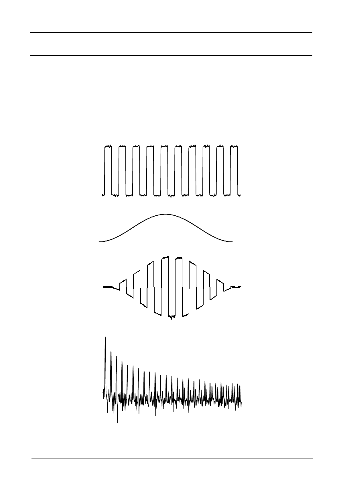
Oscilloscope Mode - The « Horizontal » Menu
Oscilloscope Mode (cont’d)
The sub-menus are used for selecting a type of window.
Rectangular
Hamming
Hanning
Blackman
Before calculating the FFT, the oscilloscope weights the signal to be
analyzed by a window acting as a bandwidth filter. The choice of window
type is essential to distinguish between the various beams of the signal
and to make accurate measurements.
Time-related
representation of
signal to be analyzed
Weighting window
Weighted signal
Frequency
representation of
signal calculated by
FFT
III - 48 Two-channel digital oscilloscopes, 60 MHz or 100 MHz
Page 49

Oscilloscope Mode - The « Horizontal » Menu
Oscilloscope Mode (cont’d)
The final duration of the design interval results in a convolution in the
signal frequency domain with a function sinex/x.
This convolution modifies the graphic representation of the FFT because
of the side lobes characteristic of the sinex/x function (unless the interval
of design contains an integer of periods).
Four types of window selections are available: the menus appear directly
on selection of the FFT menu.
Effects of under-sampling in frequency representation:
Window type
Rectangular window
Hanning window
Hamming window
Blackman window
Main lobe
width
- 13 dB
- 32 dB
- 43 dB
- 94 dB
Max. amplitude of side
lobe (compared to main
lobe)
4 π/N
8 π/N
8 π/N
12 π/N
If the sampling frequency is not correctly adjusted (less than or twice the
maximum frequency of the signal to be measured), the high frequency
components will be under-sampled and appear in the graphic
representation of the FFT by a state of symmetry (reployment).
•
The « Autoset » function is activated. It is a way of avoiding the above
phenomenon and adjusting the horizontal scale: the representation is
more legible.
•
The « Zoom » function is active.
The «
selected function.
»
symbol appears in front of one of the options, indicating the
Two-channel digital oscilloscopes, 60 MHz or 100 MHz III - 49
Page 50

Oscilloscope Mode - The « Display » Menu
Oscilloscope Mode (cont’d)
The « DISPLAY » Menu
(∗)
Only available in advanced mode
if the SPO Persistence mode is
not selected.
See §. Description, p. 65.
LCD adjustment
LCD contrast and brightness adjustment.
This function has the same effect as the following
(∗)
key.
Graticule
Display modes
Envelope
Zoom off
Attention
Vector
Used for displaying grid or not.
There are two available display modes if the SPO Persistence mode has not
been selected :
A vector is traced at the centre of the sample.
The minimum and maximum observed on each horizontal position of the
screen are displayed. This mode is used to display drifting in time or
modulation.
The “
” symbol indicates that the display mode is active.
Initiates return to the original screen size, after zooming in on part of the
screen.
•
•
zoom mode.
This function is inactive if the SPO Persistence mode is activated.
This menu can also be called up by clicking with the mouse right key inside
the trace display zone.
This function is inactive unless the screen is in zoom mode.
The letter Z in the trace parameter and time base zone denotes the
III - 50 Two-channel digital oscilloscopes, 60 MHz or 100 MHz
Page 51

Oscilloscope Mode - The « Display » Menu
.
Mode Oscilloscope (cont’d)
Full screen
Full trace
Attention
causes changeover from the normal display mode to the “full screen” display
mode and vice versa.
This function is inactive if the SPO Persistence mode is activated.
The display is organized so as to leave the biggest surface area possible for
trace plotting: only the permanent settings and the automatic or manual
measurements remain
•
This function has the same effect as the key.
•
The “ ” symbol indicates that the full screen mode is active.
This function can also be called up by clicking with the mouse right button in
the trace display zone.
activates/deactivates the horizontal division of the display area by two.
The « Full Trace » function activated is indicated by :
- the presence of a horizontal continuous feature in the middle of the display area
- a graticule divided vertically into 2 zones of 8 divisions
- traces 1 and 3 assigned to the higher part of display
- traces 2 and 4 assigned to the lower part, so as to remove their superposition
The traces can be then vertically moved in both areas.
Oscilloscope
The following submenus make it possible to change from “oscilloscope” to
“XY” mode.
The “
” symbol indicates the active mode.
This is the basic operating mode.
Each trace is represented by a single colour :
CH1 = red, CH2 = green, Math3 = blue, Math4 = violet.
All the acquired points have the same intensity whatever their occurrence is.
In the example below, all the points appear with the same colour, even those
corresponding to a random signal noise.
Two-channel digital oscilloscopes, 60 MHz or 100 MHz III - 51
Page 52

Oscilloscope Mode - The « Display » Menu
Mode Oscilloscope (cont’d)
XY
(inactive in SPO)
Example
The “XY source” menu is used for assigning the desired traces to the X axes
(horizontal) and Y axes (vertical).
Validation of selections by “OK”. Exit from menu without modification by
“Cancel”.
•
Each axis is graduated into 8 divisions.
•
The selected traces are identified by a figure corresponding to their
axis.
•
The “” symbol indicates the trace selected for each axis.
Two sinusoidal signals assigned to the X and Y axis with an offset of π/2 are
then represented by a circle.
III - 52 Two-channel digital oscilloscopes, 60 MHz or 100 MHz
Page 53

Oscilloscope Mode - The « Measurement » Menu
Trace 4
Only available in advanced mode,
Oscilloscope Mode (cont’d)
The « MEASURE » Menu
(∗)
if the SPO Persistence mode has
not been selected.
See §. Description, page 65.
Attention
Reference
Trace 1
Trace 2
Trace 3
Automatic
measurements
Two-channel digital oscilloscopes, 60 MHz or 100 MHz III - 53
The Automatic Measurements, the Phase Measurement of and the
Unattached Cursors are not available in “Persistence SPO” mode.
used for selecting one of the active traces on which you want to make
automatic or manual measurements.
Only the active traces can be selected. Inactive traces appear lighter.
The «
used for opening the « automatic measurements » menu.
The measurements are made and refreshed on the selected reference
trace. All the measurements that can be made on this trace are
displayed.
(- . - -) is displayed for the measurements that cannot be made.
The window can be closed and validated by clicking on OK with the
mouse left button.
The one or two selected measurements will be displayed in the status
zone.
» symbol indicates the reference trace.
Page 54

Oscilloscope Mode - The « Measurement » Menu
Oscilloscope Mode (cont’d)
Attention
Reference memory
difference
Example
• It is possible to select two permanent measurements.
• The «
into the status zone.
• Activating automatic measurements reveals two cursors (+) on the
curve at the beginning and end of the period. Some measurements
need to be present at least one period on the screen.
• The display order corresponds to the chronological order of the
selection.
Deleting automatic measurements in the status zone is carried out using
this menu, by erasing the selected measurements (no «
the automatic measurements table).
The automatic measurements are not available in SPO Persistence
mode.
The activation of the "Reference memory difference" option is a way of
calculating the deviations for all the automatic measurements between
the selected trace and the memorized reference trace (see §. Memory
Menu p. 58).
Calculation made and displayed on one of the 19 measurements:
Vpp (
For all the measurements, calculation is made in the same way.
» symbol indicates the measurement(s) that will be entered
Reference memory difference
» symbol in
) = Vpp (Trace 1) – Vpp (Trace 1 Ref 1)
19 automatic
Vmin
Vmax
Vpp
Vlow
Vhigh
Vamp
Vrms
Vavg
Over+
Trise
Tfall
W+
W-
P
F
DC
N
Over-
Sum
•
This option is only active if a reference trace is present. It has to
correspond to the trace on which automatic measurements are to be
made ( E.g.: Trace 1 and Trace 1 Ref. 1).
•
Condition: the reference trace must have the same characteristics as
the associated trace (sensitivity and time base).
measurements
minimum peak voltage
maximum peak voltage
peak-to-peak voltage
established low voltage
established high voltage
amplitude
rms. voltage
mean voltage
positive overflow
rise time
fall time
positive pulsewidth (at 50 % of Vamp)
negative pulsewidth (at 50 % of Vamp)
period
frequency
duty cylce
number of pulses
negative overflow
summon of instantaneous values of the signal (Σ elementary areas Vs unit)
III - 54 Two-channel digital oscilloscopes, 60 MHz or 100 MHz
Page 55

Oscilloscope Mode - The « Measurement » Menu
Any change to the signal will lead to an updating of the measurements.
L L
Oscilloscope Mode (cont'd)
Measurement
conditions
Automatic
measurement
presentation
•
The measurements are made on the displayed part of the trace.
•
They are refreshed in step with acquisition.
•
If several signal periods are displayed on the screen, the measurement
will refer to the first.
•
To make automatic measurements on specific portions of the signal,
enclose the desired measurement zone with manual cursors and
markers identifying the zone.
•
Measurement precision is optimum, if two complete signal periods are
displayed
T = 1/F
W+ W-
Vmax
100%
90%
50%
Vavg
>5%T
Vhigh
Vamp Vpp
10%
0%
Trise
t0t1t2 t3t4t5
Tfall
• Positive overflow = [100 * (Vmax – Vhigh)] / Vamp
• Negative overflow = [100 * (Vmin – Vlow)] / Vamp
i n
=
• Vrms =
•
Vavg =
•
Vsum =
1
[ (y y ) ]
∑
n
i 0
i n
=
1
∑
n
i 0
=
=
ni
∑
=
0i
−
i
=
(y y )
−
i
δ×
)(y
t
i
GND
GND
2 1/2
Vlow
Vmin
>5%T
t6
Y
= value of representing zero Volt
GND
Two-channel digital oscilloscopes, 60 MHz or 100 MHz III - 55
Page 56

Oscilloscope Mode - The « Measurement » Menu
Oscilloscope Mode (cont'd)
Phase measurement
Trace1 Phase
Trace2 Phase
Trace3 Phase
Trace4 Phase
Manual
measurements
(dt, dv)
used for making trace phase measurements with respect to a reference
trace (See §. Reference Measurement).
This menu selects the trace on which phase measurements are to be made.
To deactivate phase measurements, de-select it using the same menu for
the selected phase measurement.
•
The «
•
The activation of the phase measurement, if possible, will reveal 3 cursors:
2 automatic measurement cursors on the reference trace,
1 cursor indicating ϕ on the trace, on which the phase measurements
These 3 cursors are fixed; they cannot be moved.
•
The phase measurement (in °) of the selected trace with respect to the
reference trace is indicated in the measurement display status zone
( E.g.: (1)Ph (2) = 180.0°).
•
If the measurement cannot be made, « - . - - » appears.
used for making measurements by cursor.
The measurement cursors (1 and 2) are displayed as soon as the menu is
activated.
The two measurements made are:
dt (time deviation between the two cursors)
dv (voltage deviation between the two cursors).
The measurements made and the displayed cursors are linked with the
selected reference trace (see §. Reference Measurement).
•
The «
active.
•
The measurement cursors can be moved directly with the left mouse
button. They can also be moved using the mouse by selecting the symbol
1 (cursor 1) or the symbol 2 (cursor 2) in the bargraph.
•
If the free cursor option is not active (see §. Measurement « Unattached
cursors »), the cursors will remain linked to the reference trace during
movements. If this option is active, the cursors can be moved anywhere
on the screen.
•
dt and dv measurements with respect to the selected reference are
indicated in the measurement display status zone.
» symbol indicates the selected trace for phase measurement.
are made.
» symbol indicates that the manual measurements (dt, dv) are
E.g. : (1)dt = 500,0 µs, dv = -6,400 V
Manual phase
measurement
III - 56 Two-channel digital oscilloscopes, 60 MHz or 100 MHz
used for making phase measurements with 3 cursors: 2 identified cursors
« 1 and 2 » identical to those of the manual measurements and a 3rd free
cursor with respect to which the phase measurement is made (see
"Unattached cursors" menu for the movement of cursors "1 and 2").
•
The « » symbol indicates that the manual phase measurement is active.
•
When this menu is active, the 3 cursors are present if at least one signal is
active.
•
The cursor identified ϕ can be moved freely even if the "Unattached
cursors" menu is not active.
•
The phase measurement (in °) between these cursors is indicated in the
measurement display status zone.
E.g.: (1)Ph = 130.0 °
Page 57

Oscilloscope Mode - The « Measurement » Menu
Oscilloscope Mode (cont'd)
Unattached cursors
Particular case
used for linking or not linking the manual measurement cursors (1 and 2)
to the reference trace.
When the "Unattached cursors" menu is selected, cursors 1 and 2 can
be moved freely over the screen.
• The «
active.
• To deactivate this menu, de-select it with the mouse.
• For automatic measurements and automatic phase measurements, the
cursors are fixed: they cannot be moved. The "Unattached cursors"
menu will be inactive.
In the case of "Automatic measurements" and manual measurement
activation:
If the manual cursors and automatic markers are displayed together, the
automatic measurements will be made on the portion of the trace defined
by the manual cursors.
If the portion defined by the manual cursors is too restricted to make the
selected automatic measurements [in this case, the fixed markers (+) are
not displayed], the selected automatic measurements will be impossible
and «
»
symbol indicates that the "Unattached cursors" menu is
-.--
» will appear in the measurement display zone.
De-select the automatic measurements to validate the manual
measurements (dt, dv).
Two-channel digital oscilloscopes, 60 MHz or 100 MHz III - 57
Page 58
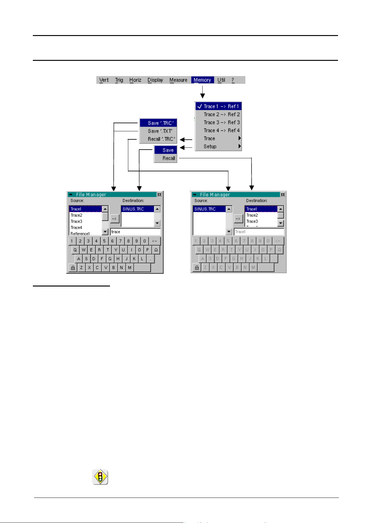
Oscilloscope Mode - The « Memory » Menu
stored in the reference memories. The references (Ref. 1, 2, 3, 4) appear
the corresponding trace has
Oscilloscope Mode (cont'd)
The « MEMORY » Menu
Trace1 Ref. 1
Trace2 Ref. 2
Trace3 Ref. 3
Trace4 Ref. 4
Attention
used for storing the selected trace in its volatile reference memory
( E.g.: Trace 1 in Ref. 1).
The 4 traces have their reference memory.
If the SPO mode is active in the oscilloscope, the traces may not be
greyed.
• For optimum comparison : the reference trace must have the same
characteristics as the associated trace (sensitivity and time base).
• A trace can only be saved to the reference memory if it is present on the
screen.
• The memorized traces appear in plain language, together with their
reference number.
• The « » symbol in the menu indicates that
been saved to the reference memory and must be present on the
screen.
• A reference trace cannot be moved.
• A reference memory can be deactivated by de-selecting it from the
menu.
A reference memory is volatile, it can be lost at the extinction of the
instrument.
III - 58 Two-channel digital oscilloscopes, 60 MHz or 100 MHz
Page 59

Oscilloscope Mode - The « Memory » Menu
Oscilloscope Mode (cont'd)
Trace
Save .TRC
Save.TXT
This menu is used for saving (to the non-volatile memory) or recalling the
trace of a reference memory. Saving can be in two formats: « .TRC » or
« .TXT ».
The « File copy » menu is suited to the type of selected format.
Saving of the files for recalling on the oscilloscope screen
The saving files will take the extension .TRC; they can be recalled in the
« Trace Recall » menu.
saving of files for export to another application
Saving files take the extension .TXT; they cannot be recalled by the « Trace
Recall » menu for screen display. However, they can be exported in a
standard format use in another software (spreadsheet).
( E.g.: Microsoft EXCEL) using the menu « Util Files ».
The selection made opens a « File Copy » menu.
∗
Then in the "Source" pull-down menu, select the trace or the reference
memory which is to be recorded.
The trace or the reference memory to be saved will appear in gray. The
selection will be made using the left mouse key.
•
Only the traces and reference memories on the screen will be entered into
the "Source" menu and therefore be selectable.
•
If all the traces and all the reference memories are present on the screen,
the scrollbar to the right of the menu will allow movement through the list.
∗
A default backup file name is proposed above the keyboard. It can be
modified using the virtual keyboard and the mouse.
The key is used for deleting the displayed letter preceding the cursor in
this zone.
∗
Once the name has been written, the key records it by entering it into the
destination menu and closes the menu. The backup file takes the extension
.TRC (internal format) or .TXT (text format), in accordance with the previous
selection.
Exit from the menu without backup is obtained by clicking with the left mouse
key on the icon at the top right of the window.
•
The file name is limited to a maximum of 15 characters + the extension,
otherwise the following message appears : “File name too long”.
•
As soon as the mouse pointer is dragged over a destination file (without
clicking), the name is accompanied by its recording date and time, and its
size.
•
If the name already exists or is not compatible, an error message will
appear.
Two-channel digital oscilloscopes, 60 MHz or 100 MHz III - 59
Page 60

Oscilloscope Mode - The « Memory » Menu
Oscilloscope Mode (cont'd)
Recall.TRC
Configuration
when selected, opens a « File Copy » menu.
In the pull-down Source menu is the .TRC file list recorded using the
« Trace Recall.TRC » menu.
The file name selected for recalling appears in gray. Selection is made
using the left key of the mouse.
∗ After selecting the file to be recalled, the destination menu indicates the
trace on which it should be restored. The selected destination trace (1 to
4), using the mouse left key to restore the signal, appears in gray. It is
also indicated in the lower zone of the screen.
∗ The trace to be recalled and its destination are selected, then the key
is used for performing the operation and closing the menu.
Exit from the menu without using this recall feature is obtained by clicking
the mouse left key on the icon at the top right.
• If the selected destination trace is already present on the screen, it will
be replaced by the recalled trace.
• When a trace is recalled, Mx appears in the destination trace
parameters. The sensitivity, coupling and bandwidth limit become
those of the restored trace (they cannot be modified).
• In this menu, the virtual keyboard is ineffective.
used for saving or recalling an equipment configuration.
Save when selected, opens the « File copy » menu.
∗ In the Source menu is a file called « Configuration ». It contains the
equipment configuration parameters when this menu is opened.
∗ A save file name is proposed above the virtual keyboard. It is used for
modifying it (left mouse key).
∗ When the source file name has been entered, the key is used for
recording the configuration by transferring it into the destination menu
and closing the menu (save file: extension .CFG).
Exit from the menu without saving is obtained by clicking the icon at the
top right of the window, with the left mouse key.
•
The file name is limited to a maximum of 15 characters + its extension.
As soon as the mouse pointer passes over a source file (without a
click) it is accompanied by its recording date, recording time and size.
•
If the name already exists or is incompatible, an error message will appear.
Recall
when selected, opens the « File copy » menu.
∗ In this pull-down "Source" menu is a list of files (.CFG) recorded using
the "Configuration « Configuration Save » menu.
The file name, selected for recalling, appears in gray. Selection is by
the left mouse key. The scrollbar on the right is used for moving
through the list.
∗ With the source file selected, the key is used for recalling the item.
∗ Exit from the menu without recalling is obtained by clicking with the
left mouse key at the top right of the window.
• In this menu, the virtual keyboard is ineffective.
III - 60 Two-channel digital oscilloscopes, 60 MHz or 100 MHz
• The default config file is used for restoring the works configuration.
Page 61

Oscilloscope Mode - The « Utilities » Menu
Oscilloscope Mode (cont'd)
The « UTIL » Menu
(∗)
(∗) USB : when the USB cord has been detected
1
6
xx/xx/06
xx/xx/07
Two-channel digital oscilloscopes, 60 MHz or 100 MHz III - 61
Page 62

Oscilloscope Mode - The « Utilities » Menu
Oscilloscope Mode (cont'd)
Files
File type
Selection of the "File Management" menu.
It contains the files which have been:
•
recorded since the instrument was first used
•
created since the last startup.
The files will only be saved once and for all when the
instrument is switched off using the ON/STD BY key :
If there is a mains power cut during saving of the configuration, the files in the
file manager will be lost.
The configuration back-up files (.CFG),
for traces in oscilloscope mode (.TRC),
for traces in SPO persistence mode (.PER),
for sampling (.TXT),
for functions (.FCT),
for printing (.PRN, .PCL, .EPS, .BMP, .GIF)
are accompanied by the date and time when they were saved and their size.
The selected file appears in grey. The scrollbar on the right is used for moving
through the list.
Selection of the file type required, using the corresponding filter:
.CFG .TRC .PER .FCT .PRN .PCL .EPS .BMP .GIF .REC .TXT
The mouse is used for selection.
" ∗. ∗ " can be used to select all the file types.
The storage capacity of the file manager is 15 Mbyte.
Open
Erase
Erase*.*
Export
causes restoration of the file selected by the “File Copy” menu.
deletes the selected file.
deletes all the files the extension of which has been selected in “File type”.
transmits the file over the active communication interface (RS232 or
USB/CENTRONICS), network.
You can exit from this menu by pointing with the mouse on the icon in the top
right-hand corner of the window.
III - 62 Two-channel digital oscilloscopes, 60 MHz or 100 MHz
Page 63

Oscilloscope Mode - The « Utilities » Menu
Oscilloscope Mode (cont'd)
I/O port config.
RS 232
Speed
Format
Parity
Stop bits
Protocol
Configuration of the
"Network" menu
Physical address
Selection of the "RS232" or "Network" menus.
This menu can be used to configure the "serial" remote programming interface
or the "network" interface (ETHERNET).
This interface uses the connector (SUBD25) at the back of the instrument.
selects the transmission speed : 300 to 115,200 Baud.
selects the word length: 7 or 8 bits.
selects the type of parity: even, odd or no parity (none).
selects the number of stop bits (1 or 2 stop bits).
selects the serial link management mode.
Hard Hardware: the protocol is provided by the RTS and CTS lines
of the RS232 link.
Soft Software: use of the XON and XOFF characters to synchronize
transmission and reception of the messages (reduced "3-wire" link)
None No protocol checking
•
The "" symbol indicates the selected option.
•
The option can be modified using the stylus.
(Ethernet)
(RJ45 connector)
corresponds to the address of the oscilloscope on the Ethernet network.
This address cannot be modified (it is specific to the instrument)
Example: 00-50-C2-29-10-00
IP address
Printer or LPD server:
IP address
Name
corresponds to the IP address of the oscilloscope on the Ethernet network.
This address can be input automatically or manually with the keyboard, after
selecting the zone to be modified.
An IP address can be assigned automatically by a DHCP server, if the server
is accessible, using the icon "supplied by a DHCP server".
Example: 132.147.200.74
corresponds to the IP address of the printer (or PC) to which the printer is
connected. In this case, the "LPD Server" software needs to be installed.
This address must be input manually with the keyboard, after selecting the
zone to be modified.
Example: 132.147.240.1
Name of the printer as it appears in the printing server (or PC). If the printer is
connected directly to the network, do not enter anything here.
This key is accessible in the "Advanced" mode only.
It gives access to the manual programming of the Subnet Mask and to the
programming of the IP address of the Gateway.
Validation of the selections by "OK". Exit from the menu without modification by
"Cancel".
USB to RS232
Two-channel digital oscilloscopes, 60 MHz or 100 MHz III - 63
Configures itself automatically, as soon as the user connects the
oscilloscope to the PC by means of a cable USB.
When USB to RS232 interface is used, exit SUBD25 is automatically
configured in CENTRONICS.
Page 64

Oscilloscope Mode - The « Utilities » Menu
Oscilloscope Mode (cont'd)
Hardcopy
Configuration
Option
Port
when selected, opens the « Hardcopy » menu.
This menu is used for selecting the print format or the printer type, as well as
the communication port that will be used for making hardcopies.
The printer type or selected format will appear in gray. Selection uses the left
mouse key. The scrollbar on the right is used for moving through the list of
types or the printer languages.
used for choosing color or black/white printing.
used for selecting the interface to be used for print data transfer: Network,
RS232 or USB, CENTRONICS or to file.
•
If the RS232C interface is selected, the parameters (speed, format, parity,
stop bit, protocol) must be configured in the "Config I/O Ports" menu. Check
that the configuration matches the configuration of the peripheral
device connected to the instrument.
•
If the "Network" option is selected, the parameters (IP address, printer) must
be configured in the « Config I/O Ports Network" menu).
•
The "File" option is a way of recording the hardcopy in a file.
".bmp" and ".gif" image formats can be used directly in the Windows
applications (word processing, presentations, etc.). As soon as the printout
is activated, the "File copy" menu opens and you have to enter the name
of the file generated (see "Trace Save" menu).
when selected, opens the « Configuration » menu.
This menu is used for configuring the equipment.
Date/time
Language
Screen saver
Automatic switch
updates the date (day, month, year) and the time (hour, minute, second).
Selection is by the left mouse key using the scrollbars located either side of
the parameters to be set.
The clock starts when the menu is closed.
selects the language in which the menus are written.
5 options are possible: french, english, german, italian, spanish.
used for setting the screen to standby after a defined period of time to
minimize the consumption of the equipment and screen aging.
4 options are possible: 15 min, 30 min, 1 h, none.
The screen is reactivated by pressing any unused key on the front panel or
moving the mouse.
used for setting the equipment to standby after a defined period of use so as
off
to limit the consumption of the unit.
In this case, the equipment configuration is saved before cutoff.
4 options are possible: 30 min, 1 h, 4 h, 24 h.
The equipment is reactivated using the key shown opposite.
•
The « » symbol indicates the selected option.
•
The option can be modified using the left mouse key.
Selection validation by « OK ». Exit from menu without modification by
« Cancel ».
III - 64 Two-channel digital oscilloscopes, 60 MHz or 100 MHz
Page 65

Oscilloscope Mode - The « Utilities » Menu
math1, math2, math3, math4
Oscilloscope Mode (cont'd)
System
Startup sequences
Use duration
Last calibration date
Next calibration date
« Advanced »
Mode
Menus present in
« Advanced » mode
only:
used for sending the user information about the life of the equipment
starting from commissioning.
indicates the number of equipment starts.
indicates the total utilization time in hours.
indicates the date of the last equipment calibration.
indicates the date of the next equipment calibration. Periodic equipment
calibration is necessary to guarantee the unit within the specifications.
For any checks of the equipment, see §. Maintenance, Metrological
checking.
Exit from this menu is by clicking on the icon at the top right with the left
mouse key.
When activated, the « Advanced » mode gives access to all the
equipment functions.
Conversely, when this mode is not active, the advanced equipment
functions no longer appear in the menus.
accessible through the « Vert » menu
repetitive signal averaging
accessible through the « Horiz » menu
XY
unattached cursors
Attention
•
The « » symbol indicates that the "Advanced" mode is active.
•
Modification uses the mouse left key.
•
By default, the "Advanced" mode is not active.
In “Persistence” display, Math {1, 2, 3, 4} functions, Repetitive signal,
Averaging and XY modes are inactive and appear in grey ...
In "non-advanced" mode, the instrument's configuration is not
saved when it is shut down using the ON/STD BY key and the
default factory configuration is loaded at next start-up.
accessible through the « Display » menu
accessible through the « Measurement »
menu
Two-channel digital oscilloscopes, 60 MHz or 100 MHz III - 65
Page 66

Oscilloscope Mode - The « Help » Menu
Oscilloscope Mode (cont'd)
The « ? » Menu
Help
when selected, opens the « Help » menu.
This menu is used for activating on-line help using the equipment keys,
in the same way as the key shown opposite.
MTX3354, VX.XX/XXX
About
Reminder
The keys are used for scrolling through the description of the keys
on the front panel.
Any press on a key of the keyboard causes the display of the on-line
help of the depressed key. The functions associated with the keys are
not launched.
The key name is used above the explanation.
Exit from the menu is obtained by clicking with the left mouse key on the
icon at the top right of the window.
when selected, opens an information file with :
- the name of the instrument
- the software version
- the instrument version
This file refers to the equipment software version and gives its date of
creation.
Exit from the menu is by OK.
By connecting you on the website www.chauvin-arnoux.com you will be
able to record the software, then to download the updates.
By the E-mail address, you will contact a technical hot-line ; a technician
will answer your possible questions.
III - 66
Two-channel digital oscilloscopes, 60 MHz or 100 MHz
Page 67

Oscilloscope Mode with "SPO" - Keys - Display
Parallel
Oscilloscope Mode with "SPO"
Smart Persistence Oscilloscope
The Keys
With "SPO", the keys operate exactly as described for the Oscilloscope
mode without "SPO" (see p. 13).
The message "Impossible in this mode!" is displayed if the key
pressed is not active.
Display
Presentation The "Smart Persistence Oscilloscope" mode (SPO) is activated using the
"Display" menu in Oscilloscope mode (see p. 50).
"SPO" persistence:
•
reveals unstable phenomena, transients and glitches
•
shows the evolution of the signal over time, jitters and modulations
as in analogue oscilloscopy
•
causes persistence of the acquisitions during a preset time for
observation of an accumulation of traces.
The brightness or the colour allocated to the point on the screen will
diminish if it is not renewed in a subsequent acquisition.
3 dimensions are involved in acquisition:
- time
- amplitude
- occurrence, which is a new dimension. See next page.
Acquisition
The "SPO" processing optimizes detection of transient phenomena:
without "SPO"
The acquisition, display and
processing tasks are sequential.
with "SPO"
The acquisition and processing tasks
are in parallel.
The number of acquisitions per
second can be multiplied by 100. The
interval between two acquisitions is
therefore significantly reduced.
1 acquisition = 1 display
Processing
Acquisition
Display
n acquisitions = 1 display
Fast
Acquisition
processing
Screen representation of 500 points
out of 50,000 points acquired.
Display of a segment to link the
points together.
Screen representation of 50,000
points acquired, using a smart
compression system.
Display of a cloud of points which are
not linked together. No interpolation.
Display
Two-channel digital oscilloscopes, 60 MHz or 100 MHz IV - 67
Page 68

Oscilloscope Mode with "SPO" - Keys - Display
4.
Menu bar
1.
Status area
rent
Oscilloscope Mode with "SPO" (cont’d)
Smart Persistence Oscilloscope
Occurrence
Examples
This provides a statistical dimension to the distribution of the samples.
The colour or brightness highlight the irregularities in the signal. They are
also used to differentiate between rare points and frequent points.
It is possible to modify this parameter by adjusting the duration of
persistence (see p. 72, Display menu with "SPO").
•
Monochrome representation in green:
- the dark green points are renewed
frequently,
- the light green points are renewed
less frequently.
•
Multi-colour representation:
- the red points are renewed
frequently,
- the violet points are renewed less
frequently.
Display
Composition
3. Display area
Direct access to
main settings
IV - 68 Two-channel digital oscilloscopes, 60 MHz or 100 MHz
2. Command area
Display and
adjustment of cur
Page 69

Oscilloscope Mode with "SPO" - Keys - Display
representation (see p. 73)
Oscilloscope Mode with "SPO" (cont’d)
Smart Persistence Oscilloscope
1. Status area
Tool bar
Bargraph: see p. 18.
Adjustment:
Permanent
See p. 18.
adjustments
Cursor
See p. 18.
measurements
Automatic
Impossible in this mode.
measurements
Adjustment of persistence
duration (see p. 72)
Refreshing of display:
all the traces displayed on the
screen are erased.
Monochrome
representation (see p. 73)
Multicolour
2. Control area
3. Display area
Notes
The parameters which differ are described below:
No display of ZOOM mode
(Z), option unavailable.
The MATH functions are not
available.
No FFT function,
FFT not available.
Analogue persistence has
been activated!
See p. 21.
This symbol (ref. 5, p. 21) is not visible: automatic measurements are
not available in "SPO" mode.
Two-channel digital oscilloscopes, 60 MHz or 100 MHz IV - 69
The Zoom box (ref. 9, p. 21) is present, but inactive because the
Zoom option is not available in "SPO" mode.
Page 70

Oscilloscope Mode with "SPO" - Keys - Display
Oscilloscope Mode with "SPO" (cont’d)
Smart Persistence Oscilloscope
Menu accessible from
display area
When the mouse pointer is placed in the display zone, a right click gives
direct access to a menu concerning the display.
Note
These options are also accessible via the Display menu in "SPO",
see p. 72.
4. Menu bar
All the oscilloscope functions can be accessed via the main menus.
IV - 70 Two-channel digital oscilloscopes, 60 MHz or 100 MHz
Page 71

Oscilloscope Mode with "SPO" - The "Vertical" menu
Oscilloscope Mode with "SPO" (cont’d)
Smart Persistence Oscilloscope
The "VERT" menu
(∗)
(∗)
(∗)
(∗)
Display See p. 25.
ch1 ch2 ch3 ch4 See p. 25.
The "TRIG" Menu
See p. 36.
These greyed functions
(∗)
are not available.
Special case
The "HORIZ" Menu
Single mode:
The persistence duration is forced to "Inf." (no ageing of the samples).
Every time there is a new acquisition, the traces are cumulated.
To refresh the screen, use the button .
(∗)
(∗)
(∗)
The greyed functions
are not available.
Repetitive Signal
Min/Max Acquisition
Two-channel digital oscilloscopes, 60 MHz or 100 MHz
This greyed function is permanently active. It is ticked by default and
cannot be deselected.
See p. 45.
IV - 71
Page 72

Oscilloscope Mode with "SPO" - The "Display" Menu
Oscilloscope Mode with "SPO" (cont’d)
Smart Persistence Oscilloscope
(∗)
(∗)
(∗)
(∗)
The "DISPLAY" Menu
(∗)
The greyed functions
are not available.
Oscilloscope
SPO Persistence
XY
Adjustment of LCD
Grid
Mode
Zoom off
Full screen
Full trace
Select the "Oscilloscope" mode.
The "" symbol indicates that this mode is active.
Select the "Smart Persistence Oscilloscope" display mode.
The "" symbol indicates that this mode is active.
This display mode is not available with "SPO".
See p. 50.
See p. 50.
This function is not available with "SPO".
This function is not available with "SPO".
This function is not available with "SPO".
See p. 50.
IV - 72 Two-channel digital oscilloscopes, 60 MHz or 100 MHz
Page 73

Oscilloscope Mode with "SPO" - The "Display" Menu
Example
Oscilloscope Mode with "SPO" (cont’d)
Smart Persistence Oscilloscope (SPO)
Persistence
parameters
Instructions
Representation
Monochrome
Duration
opens a dialogue box giving access to all the specific "SPO" settings.
These settings are also available in the settings bar (see p. 69).
selects the display duration (100 ms, 200 ms, 500 ms, 1 s, 2 s, 5 s,
10 s, infinite) for the points acquired.
A point which is not renewed will disappear according to the duration set
for it. On the screen, this point will fade until it disappears.
Ageing only comes into effect in the presence of a trigger.
In "Trigger mode", a trace will not age if the oscilloscope is not triggered.
•
To detect rare phenomena, you must set a duration ≥ 2 s, i.e.: 2 s, 5 s,
10 s or infinite.
•
You are advised to adjust this duration to show the statistical distribution
of the points displayed.
Selects the representation:
- monochrome or
- multi-coloured
This is a unilateral choice: either all the channels are monochrome,
or all the channels are multi-coloured,
The intensity of a point is represented by a single colour, from the darkest
shade to the lightest:
- the darker the colour, the greater the frequency of point renewal
- the lighter the colour, the rarer the point is
Example: Monochrome channel: shading of green for channel 2
Direction of decreasing occurrence of the points
Multicolor
Tool bar Choice of representation in the status area:
The intensity of a point is shown by several colours:
- the warm colours (red, orange, yellow) show the points renewed
frequently,
-
the cold colours (green, blue, violet) show the rarer points.
Example: Multi-colour channel
Direction of decreasing occurrence of the points
- if "Bargraph" is selected, it is displayed (see p. 69),
-
if "Adjustment" is selected, the settings bar is displayed (see p. 69).
Two-channel digital oscilloscopes, 60 MHz and 100 MHz IV - 73
Page 74

Oscilloscope Mode with "SPO" - The "Measurement" Menu
Oscilloscope Mode with "SPO" (cont’d)
Smart Persistence Oscilloscope
The "Measurement" Menu
(∗)
These functions are
not available.
Reference
Trace 1
Trace 2
Trace 3
Trace 4
See p. 52
(∗)
(∗)
This function is ticked
because it is
permanently active
Automatic
measurements
Phase measurement
Phase Trace 1
Phase Trace 2
Phase Trace 3
Phase Trace 4
Manual
measurements
(dt, dv)
Manual phase
measurement
Unattached cursors
Automatic measurements are not available.
This function is not available.
See p. 52.
The function with the cursor attached to the curve is not available.
See p. 52.
The function with the cursor attached to the curve is not available.
See p. 52.
This function is permanently active. It is not possible to deselect it.
IV - 74 Two-channel digital oscilloscopes, 60 MHz or 100 MHz
Page 75
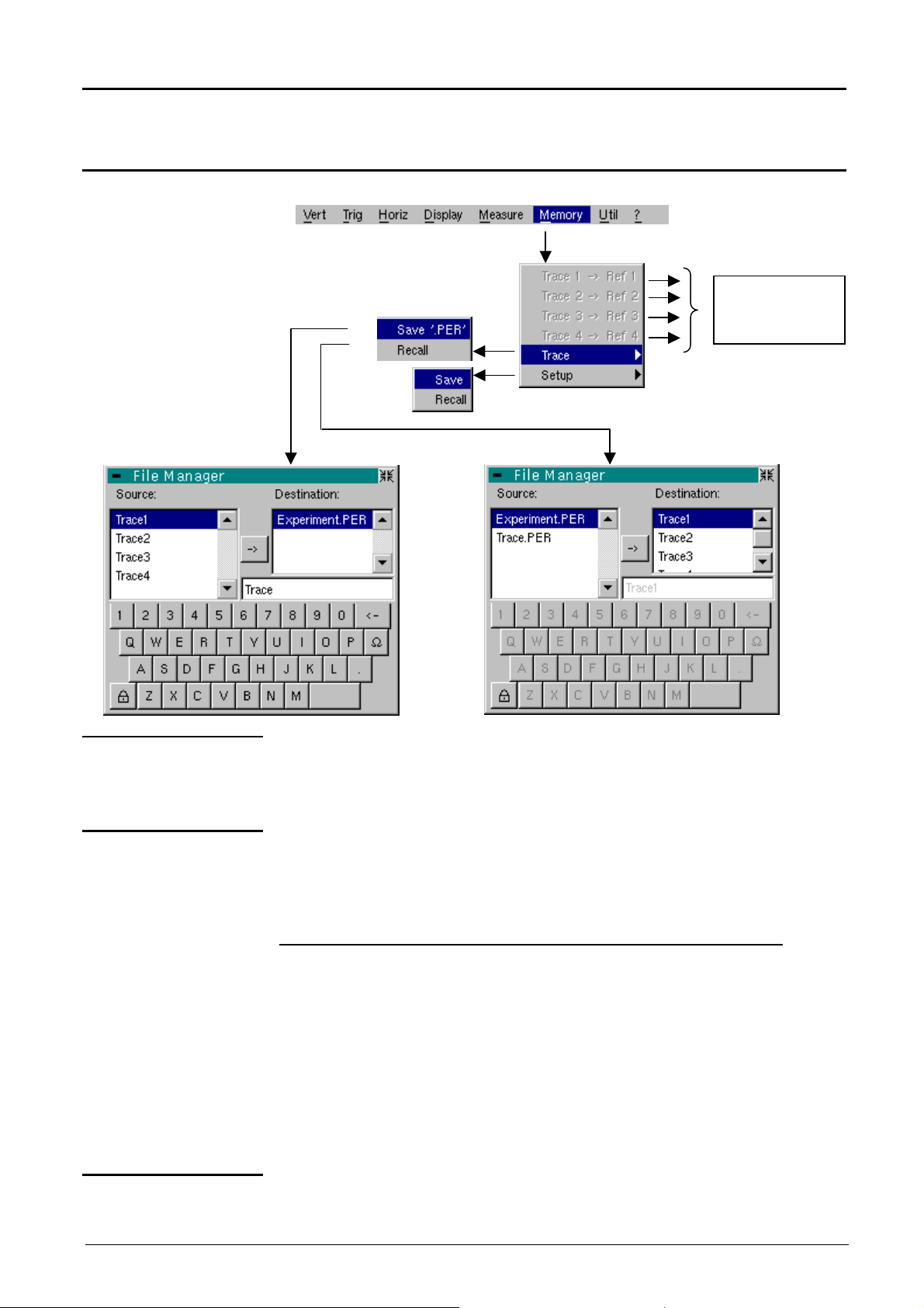
Oscilloscope Mode with "SPO" - The "Memory" Menu
Oscilloscope Mode with "SPO" (cont’d)
Smart Persistence Oscilloscope
The "MEMORY" Menu
These greyed
functions are
not available.
Trace 1 Ref. 1
Trace 2 Ref. 2
Trace 3 Ref. 3
Trace 4 Ref. 4
Trace
Save '.PER’ Saving of the files for subsequent recall on the oscilloscope screen
Recall
These functions are not available.
Saving (in non-volatile memory) or recall of a trace.
It is saved in the format: ‘.PER’.
The "File copy" menu is adapted to the type of format selected.
The back-up files will take the suffix ‘.PER’ ; they can be recalled in the
"Trace Recall" menu.
The back-up procedure for a file is identical to the procedure in
oscilloscope mode (see p. 59). Only the file's suffix changes.
Opens a "File Copy" menu when selected.
The "'Source" list contains a list of the ‘.PER’ files which have been
recorded using the "Trace Save.PER".
The recall procedure for a file is identical to the procedure in oscilloscope
mode (see p. 59). Only the file's suffix changes.
Configuration Saving or recalling of an instrument configuration. The procedure is identical
Two-channel digital oscilloscopes, 60 MHz or 100 MHz
to the procedure in oscilloscope mode (see p. 60).
IV - 75
Page 76

Oscilloscope Mode with "SPO" - The "Utilities" Menu - "Help"
Oscilloscope Mode with “SPO” (cont’d)
Smart Persistence Oscilloscope
The « UTIL » Menu
See p. 61.
The « ? » Menu
See p. 66.
V - 76 Two-channel digital oscilloscopes, 60 MHz and 100 MHz
Page 77

«
Harmonic Analysis » Mode - Display
« Harmonic Analysis » Mode
Installation
The keys
Display
Presentation
The « Harmonic Analysis » mode is an option of the oscilloscope which
must be installed to function.
The instructions of installation are on the diskette (readme.txt file)
delivered with this option.
Same as the ones described in the « Oscilloscope » mode (see p. 13).
If a function is impossible, a corresponding message is displayed on the
screen.
Harmonic analysis displays the fundamental and the 31 harmonics of
the signal present at ch1 or ch2 input.
In this mode, the trigger is automatic and the time base is adaptive, and
not manually adjustable.
This analysis is reserved for signals whose fundamental frequency is
included between 40 Hz and 5 kHz.
The adjustments of the channel parameters remain active (Sensitivity/
Coupling, Vertical scale, Bandwidth limit).
Only the channels (and not the functions) can be the subject of harmonic
analysis.
The harmonic analyses of the two signals can be displayed
simultaneously.
Display
Two-channel digital oscilloscopes, 60 MHz or 100 MHz V - 77
Page 78

adjustments
information
display
harmonic
« Harmonic Analysis » Mode (cont’d)
«
Harmonic Analysis » Mode - Display
Composition
1. Display zone
Trace
Harmonic mode display is divided into 4 functional zones:
4. Menu base
1. Display zone
Direct access
to current
3. Status zone
2. Control area
Selection of
fundamental or
Display of
information about
selected
fundamental or
harmonic
displays the result of harmonic analysis of a single trace (ch1 or ch2) or
the 4 traces simultaneously (ch1 and ch2).
The harmonic analysis of the ch1 and ch2 trace is shown in the same
color as the trace.
The display appears as a bar chart, whose vertical axis is graduated as a
percentage of the fundamental amplitude (from 0% to 100% every 25%).
2. Control zone
The horizontal axis represents the harmonics, i.e.:
•
the fundamental (F) and the first 16 harmonics
•
the even harmonics from 2 to 30
•
the odd harmonics (from 3 to 31) and the fundamental (F)
This breakdown of the harmonics is used for selecting, with the mouse left
key, the fundamental (F) or one of the harmonics, ( E.g.: Ref.
Harmonic 5) for making automatic measurements of the selected element.
•
The « » symbol indicates the selected harmonic.
•
See the "Display" menu for the selection of the harmonics.
Display of trace parameters in trace color:
validity, coupling, bandwidth limit, sensitivity
•
When the mouse is dragged over the parameters of a channel, the
right button is used for directly opening the associated menus
« Sensitivity/Coupling » and « Vertical scale ».
•
The left key of the mouse is used for channel validation.
•
The « » symbol indicates whether the channel is selected.
V - 78 Two-channel digital oscilloscopes, 60 MHz or 100 MHz
Page 79

«
Information display about
traces
harmonic
Harmonic Analysis » Mode - Display
« Harmonic Analysis » Mode (cont’d)
3. Status zone
The « Signal» zone
The
« Fundamental Ref. »
or « Harmonic » zone
The status zone returns the automatic measurements made on the
signals and the selected harmonic.
Signal
Signal
Information display about
fundamental or selected
indicates:
- the active channel(s): ch1 and/or ch2
- the root mean square (RMS) of the signal in V
- the harmonic distortion factor (THD) in %
indicates, for the fundamental or the selected harmonic, (
E.g.: Ref.
Harmonic 3) :
- its value as a % of fundamental
4. Menu toolbar
- its phase in ° with respect to the fundamental
- its frequency in Hz
- its rms. voltage in V
The same menu toolbar is used as in "Oscilloscope" mode; some menus
are adapted to the "Harmonic Analysis" mode and the others are not
active.
Two-channel digital oscilloscopes, 60 MHz or 100 MHz V - 79
Page 80
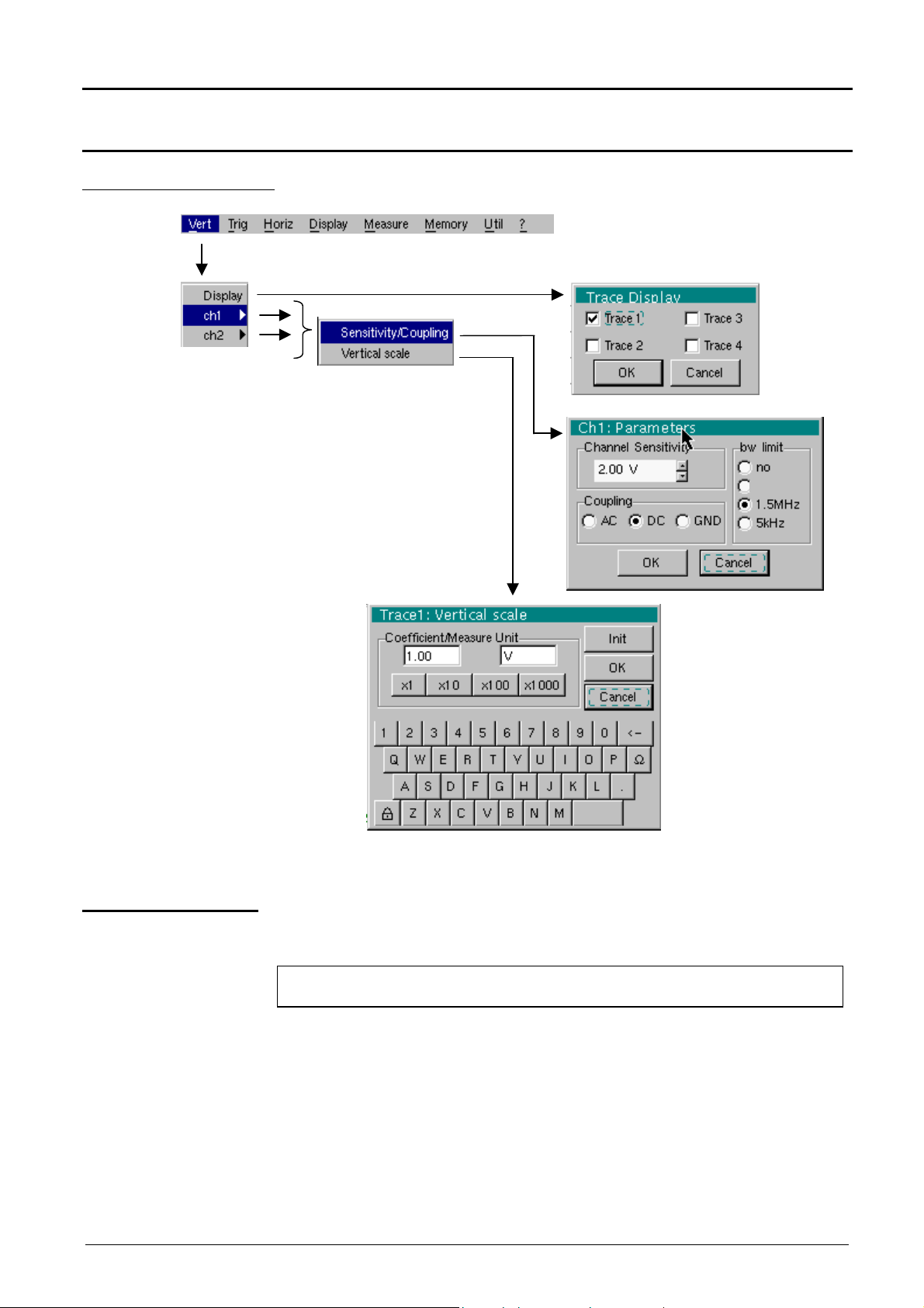
Harmonic Analysis Mode - The « Vertical » Menu
15MHz
Harmonic Analysis Mode (cont'd)
The « VERT » Menu
Display
when selected, opens the "Trace display" menu used for validating or
invalidating the traces.
Validation of selections by « OK ». Exit from menu without modification by
« Cancel ».
• The « » symbol in front of a trace indicates its validation.
• Harmonic analysis of the ch1 and ch2 signal is represented in the
colour of the trace.
• In the "Harmonics" mode, only the channels (and not the functions) are
the subject of harmonic analysis.
V - 80 Two-channel digital oscilloscopes, 60 MHz or 100 MHz
Page 81

Harmonic Analysis Mode - The « Vertical » Menu
Harmonic Analysis Mode (cont'd)
ch1 ch2
Sensitivity/Coupling
Channel Sensitivity
Coupling
Bandwidth limit
modifies independently the ch1 and ch2 channels parameters and the selected
trace vertical scale.
modifies the parameters of the selected channel.
modifies sensitivity of channel by scrollbar with left mouse key: from 2.5 mV to 100
V/div.
The sensitivity is given in the channel parameter display zone. It takes into
consideration the parameters of the "Vertical scale" menu.
Modification of AC - DC - GND coupling
AC : blocks DC component of the input signal and attenuates the signals
lower than 10 Hz.
DC : transmits the DC and AC components of the input signal
GND : the instrument connects intern the selected channel input to the 0 V
reference level.
The « » symbol indicates the selected coupling.
It is entered into the modified channel parameter display zone.
Limits the bandwidth of the channel and its trigger circuit to reduce display noise
and false triggering.
The bandwidth of each channel can be limited to 5 kHz, 1.5 MHz or
15 MHz. The bandwidth limit of a channel is indicated in the control area by
following symbols :
Validation of selections by « OK ». Exit from menu without modification by
« Cancel ».
15 MHz 1.5 MHz
5 kHz
Vertical scale
Coefficient
Measure Unit
Init
This menu can also be called by clicking with the right mouse key in the selected
channel parameter display zone (ch1 ch2).
defines the vertical scale of the selected channel from the current settings.
Assignment of a multiplication factor to the selected channel sensitivity.
Modification is by the mouse using the table of usable numbers after selecting the
"Coefficient" zone.
The key is used for deleting the value preceding the cursor in this zone.
Predefined values (x1, x10, x100, x1000), corresponding to standard probe
coefficients and can be assigned directly.
The sensitivity value indicated in the channel parameter display will be modified
according to this coefficient.
Modification of the selected channel vertical scale unit.
This modification is made using the mouse and the table of usable characters,
after selecting the "Measure Unit" zone.
The key is used for deleting the value preceding the cursor in this zone.
The vertical scale unit will be entered into the modified channel parameter display.
re-initializes the multiplication coefficient at 1.0 and returning a measure unit in V.
Two-channel digital oscilloscopes, 60 MHz and 100 MHz V - 81
This menu can also be opened by clicking with the right mouse key in the selected
channel parameter display (ch1 ch2).
Page 82

Harmonics Mode - The « Horizontal » Menu
Harmonic Analysis Mode (cont'd)
The « HORIZ » Menu
No averaging
Average rate: 2
Average rate: 4
Average rate: 16
Average rate: 64
These menus are used for selecting an average rate to calculate an
average according to the coefficient selected on the displayed
samples.
This selected coefficient attenuates any random noise observed in a
signal.
The selectable average rates are:
no averaging,
average rate: 2,
average rate: 4,
average rate: 16,
average rate: 64.
Calculation is to the following formula:
Pixel N = Sample * 1/Average rate + Pixel N-1 (1-1/ Average rate)
with:
•
Sample: value of new sample acquired at abscissa t
•
Pixel N : ordinate of abscissa pixel t on screen at
instant N
•
Pixel N-1 : ordinate of abscissa pixel t on screen at
instant N-1
The « » symbol indicates the selected average rate.
V - 82 Two-channel digital oscilloscopes, 60 MHz or 100 MHz
Page 83

Harmonic Analysis Mode - The « Display » Menu
Harmonic Analysis Mode (cont'd)
The « DISPLAY » Menu
FundHarmonic 16
Even harmonics
Odd harmonics
These menus allow the display, according to 3 groups, of the harmonic
composition of one or four selected signals.
displays fundamental and first 15 harmonics.
displays fundamental even harmonics from 2 to 30.
displays fundamental and odd harmonics from 3 to 31.
The chosen selection appears under the composition display.
• The « » symbol under fundamental F or one of the 31 harmonics
indicates the one selected.
• The selection is preserved during a change of display.
Two-channel digital oscilloscopes, 60 MHz or 100 MHz V - 83
Page 84

Harmonics Mode - The "Utilities" Menu - The "Help" Menu
Harmonic Analysis Mode (cont'd)
The « MEMORY »
Menu
The « UTIL » Menu
The « ? » Menu
See description in "Oscilloscope" mode, p. 58.
In the "Harmonics" mode, this menu is limited to saving and recalling the
instrument configuration.
See description in « Oscilloscope » mode, p. 61.
See description in « Oscilloscope » mode, p. 66.
V - 84
Two-channel digital oscilloscopes
Page 85

Recorder Mode - Keys
Recorder Mode
Installation
The Keys
4 "UTILITY" keys
The « Recorder » mode is an option of the oscilloscope which must be installed
to function.
The instructions of installation are on the diskette (readme.txt file) delivered with
this option.
Same as the ones described in the « Oscilloscope » mode (see p. 13).
If a function is impossible, a corresponding message is displayed on the screen.
Pressing this key will configure the instrument in the following modes:
« oscilloscope »,
« harmonic analyser » (option),
« recorder » (option).
(or keypad)
LCD contrast and brightness setting (see “Oscilloscope” mode, p. 13).
Full screen display (see “Oscilloscope” mode, p. 13).
1 "AUTOSET" key
Selective
«AUTOSET»
with
1 help key
Take a screen shot (see “Oscilloscope” mode, p. 13).
No action.
(Pressing this key displays the message: “Impossible in this mode!”).
No action.
(Pressing the key displays the message: “Impossible in this mode!”).
No action.
(Pressing the key displays the message: “Impossible in this mode!”).
activating or deactivating help on the keys.
Whenever a keyboard key is pressed, on-line help will be displayed for the
depressed key (except for the key ????).
The functions associated with the keys will not be started up.
On-line help can also be deactivated with the mouse (icon at top right).
The keyboard then resumes normal operation.
Two-channel digital oscilloscopes, 60 MHz or 100 MHz VI - 85
Page 86

Recorder Mode (cont’d)
full screen display of the fault on the left of the screen
The main cursor is positioned over the trigger, on the magnified fault while
Recorder Mode - Keys
2 "ACQUISITION " keys
2 «TRIGGER» keys
3 "MEASURE" keys
No action.
(Pressing the key displays the message: “Impossible in this mode!”).
This key has two functions:
RUN = launches an acquisition
STOP = stops an acquisition
If the recorder is in memory display (see §. Memory Menu Recall “.REC”,
p. 107), the message “Impossible in this mode!” appears when this key is
pressed.
By successive pressing, selection of the different Trigger of the last selected
channel (see §. Trigger Menu, p. 97).
No action.
(Pressing the key displays the message: “Impossible in this mode!”).
The 19 automatic measurements of the reference trace are displayed (see
“Oscilloscope” mode, p. 54).
Particular case
2 "HORIZONTAL" keys
In “fault capture” (or “file capture”) mode, if the screen shows several faults at
once, the “automatic measurement” function is impossible and the message
“Impossible in this mode!” is displayed.
Selection (by succesive presses) from the traces displayed, of the reference
trace for automatic and manual measurements (see “Oscilloscope” mode, p.
53).
No action.
(Pressing the key displays the message: “Impossible in this mode!”).
Setting of " the recording time / sampling " by the encoder wheel.
H-POs. has no action. The message :”Impossible in this mode” is diplayed, if
the thumbwheel TOGGLE key is pressed.
• Action identical to that in “Oscilloscope” mode, when fault capture and file
capture mode are not selected (see p. 15).
• Fault capture or file capture mode is selected:
1st press: “Zoom on”
the auxiliary cursor is on the right of the screen.
Displacement in the list of defects by the encoder wheel.
2nd press: “Zoom off” 10 consecutive faults are displayed on the screen.
The cursors are no longer displayed.
Note : Z-pos is not active.
VI - 86 Two-channel digital oscilloscopes, 60 MHz and 100 MHz
Page 87

Recorder Mode - Keys
Recorder Mode (cont’d)
Definition of terms
used
(id. “Oscilloscope”
mode)
5 "VERTICAL" keys
Validated channel: Display enabled, trace displayed after RUN
Displayed channel: Channel validated, trace present on the screen
Selected channel: enables the modification of the sensitivity (V/div) of
this channel through the thumbwheel. The TOGGLE
key authorizes the vertical displacement of the channel
(V-POs.)
The parameters of this channel can be set using the following key :
Before pressing one of the
next keys :
The signal concerned is not
displayed.
The signal concerned is
displayed but the channel is
not selected.
The signal concerned is
displayed and the channel is
selected.
Stage 1 Stage 2 Stage 3
Press
After pressing one of these
previous keys:
The signal is displayed and
the verical channel is
selected.
The wheel encoder is
assigned to the adjustment of
its sensitivity.
Double pressing of one of those keys devalidates and erases the concerned
signal.
No action.
(Pressing the key displays the message: “Impossible in this mode!”).
In “Recorder” mode, the DC input coupling is constant. The DC symbol
is permanently displayed.
The « Recorder » mode is adapted to very low signals. In « Fault Capture »
mode : if a periodic signal of frequency > 65 Hz is injected at the inputs
(horizontal scale duration of recording = 2 s), there is no trigger.
Two-channel digital oscilloscopes, 60 MHz or 100 MHz VI - 87
Page 88

Recorder Mode - Display
4.
Menu bar
1.
Status area
information loss involving
segmented to allow the
a triggerd acquisition of
Recorder Mode (cont’d)
Display
Normal
mode display
Display in
fault capture and file
capture modes
The user views 500 points
on the screen
(in “MIN/MAX” mode) to
eliminate the risk of
information loss involving
the 50,000 points in the
memory.
The user views 500
The memory is
points on the screen
(“MIN/MAX” mode) to
acquisition of 100
eliminate the risk of
faults.
A fault corresponds to
the 50,000 points in the
memory.
500 samples.
2 modes of
visualization:·
- 10 contiguous faults
- only 1 full-screen fault
Composition
The composition of the “Recorder” mode display is identical to that in
“Oscilloscope” mode.
Reminder: The display is divided into 4 functional zones.
3. Display area
Direct access to
current settings
2. Control area
Display and
setting of current
value
VI - 88 Two-channel digital oscilloscopes, 60 MHz or 100 MHz
Page 89

Recorder Mode - Display
1
Time of acquisition of sample
1
Recorder Mode (cont’d)
1. Status area
configuration
Move to the left in
the acquisition
Standard
Time of acquisition of 1st
sample viewable in the
displayed window
memory
Three pieces of general information appear in this area:
•
The bargraph, representing the screen position and the cursors in the
acquisition memory;
•
Instrument settings (fault capture mode, zoom, etc.);
•
Acquisition times:
of the first sample that can be viewed,
of the sample under the main cursor,
of the sample under the auxiliary cursor.
Time of acquisition of
sample located under
the main cursor
located under the auxiliary
cursor
The curves displayed
10:23:10
13:23:25
17:14:20
2
are stored in the
memory
Configuration if
delayed start-up is
enabled
Screen position in the
acquisition memory
Display in fault capture
mode
Position of main/auxiliary
cursors in the acquisition
memory
Zoom active
Delayed start-up time
10:23:10
2
When the acquisition starts, the display returns to its standard configuration.
Move to the
right in the
acquisition
memory
Two-channel digital oscilloscopes, 60 MHz and 100 MHz VI - 89
Page 90
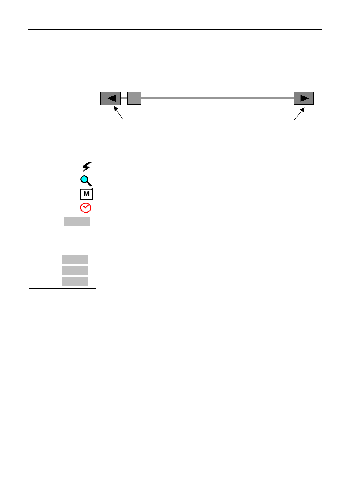
Recorder Mode - Display
magnified screen
Recorder Mode (cont’d)
Bargraph
In fault capture and file capture mode, the bargraph indicates the position of
the screen and cursors in the acquisition memory.
The main cursor is positioned on the displayed fault and the auxiliary cursor on
the right of the screen.
Movement towards the fault
immediately left of the
magnified screen
Movement towards the fault
immediately right of the
Settings
10:23:10
Signification of symbols appearing on the bargraph:
The recorder is in fault capture or file capture mode.
The horizontal zoom is active.
The curves displayed are stored in the memory.
Delayed start-up is activated.
This symbol is displayed only when delayed start-up is active.
It indicates the time at which recording will commence.
Start-up date: see §. Trigger Menu Delayed start-up, p. 98.
Acquisition times
2. Control area
10:23:10
13:23:25
17:14:20
These represent the times of:
- the first sample viewed;
- the sample located under the main cursor;
- the sample located under the auxiliary cursor.
•
Parameters of each channel and trace:
- display
- coupling
- bandwidth limit,
- zoom function,
- vertical measurements of samples under the main and auxiliary cursor.
• Indication and active adjustment of the last selected element:
- trigger level (main and auxiliary),
- horizontal gap between the time position of the auxiliary cursor and that of
the main cursor,
- vertical gap between the measurement of the auxiliary cursor and the main
cursor on the reference trace (see §. Menu Measurement Reference
p. 105),
- number of faults acquired and number of fault viewed,
- duration of recording and acquisition interval.
The time position of the trigger is not displayed as it is fixed (20 % of the
memory). The horizontal scale is not displayed.
VI - 90 Two-channel digital oscilloscopes, 60 MHz or 100 MHz
• The device indicates if the acquisition is in RUN or HOLD mode.
• The other displays (battery, etc.) are identical to “Oscilloscope” mode.
Page 91
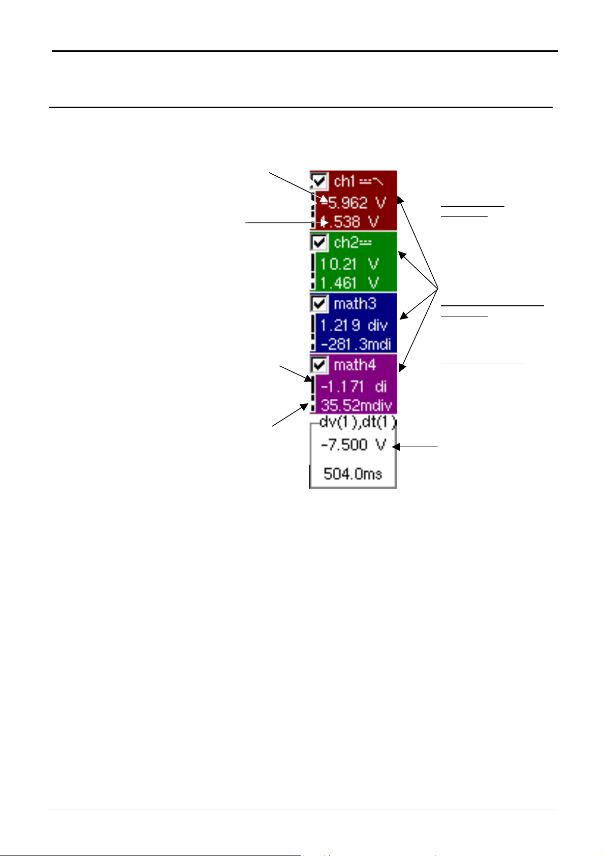
Recorder Mode - Display
the following measurement
the following measurement
Recorder Mode (cont’d)
2. Control area
(cont’d)
Measurement of sample
under auxiliary cursor
Measurement of sample
under main cursor
Symbol is a reminder that
is that of the auxiliary
cursor (solid line)
Symbol is a reminder that
is that of the main cursor
(broken line)
• The use of controls,
• the validation of channels with the mouse,
• the menus relating to the channels and functions
are identical in “Recorder” and “Oscilloscope” mode.
It is not possible to mix memorised curves (Mx) and acquired curves in
real-time Chx on the display (see §. Memory Menu
“.REC” p. 107).
The colour corresponds
to the colour of the trace.
Display of trace
parameters:
- validity
- DC coupling
- bandwidth limitation
- vertical measurement of
sample under cursors
- display of ZOOM mode
OR
Display of maths function
parameters:
- validity
- vertical measurements
OR
Display of memories:
- validity
- vertical measurements
Indication, adjustment and
trigger level (sensitivity) of
last setting selected
(
E.g. vertical and
horizontal gap between
the main and auxiliary
cursor)
Trace
Recall
Two-channel digital oscilloscopes, 60 MHz and 100 MHz VI - 91
Page 92

Recorder Mode - Display
1
1
1
1
1
Recorder Mode (cont’d)
3. Display area
Graphic elements displayed associated with the traces in this area:
•
Vertical position indicator for the reference level of each trace
•
ZOOM area selection.
•
Main cursor (permanent, moved using mouse) located at the left of the
screen by default.
•
Auxiliary cursor (permanent, moved using mouse) located at the right of the
screen by default.
•
Trigger time position indicator (fixed and located 20% across from the left of
the screen).
Its graphical representation is as follows :
Level indicators representing 5 different triggers:
- “Lower trigger” option (of the last channel selected).
- “Upper trigger” option (of the last channel selected).
- “Upper/lower trigger” option (of the last channel
selected).
The level indicator figure represents the channel concerned by this
indicator:
Example
In fault capture and file capture mode, the grid is divided into ten
sections; i.e. one section for each fault.
The cursors are no longer displayed: they reappear when a single fault is
displayed on the screen (horizontal zoom enabled: see help for key shown
here).
- “External window trigger” option (of the last channel
selected).
- No symbol is displayed: no trigger (on the last
channel selected).
- Lower trigger option on channel 1.
There can be trigger conditions on several
channels at the same time: display by selecting
the channel concerned.
VI - 92 Two-channel digital oscilloscopes, 60 MHz or 100 MHz
Page 93

Recorder Mode - Display
1
6
Recorder Mode (cont’d)
Display elements
2
1
2
9
8
Definition of display
3
4
Items Display elements
1
2
Trace displayed
3
4
5
6
7
8
9
10
Trace displayed
Indication of vertical position of reference level of the displayed
trace and identification of trace number
Indicator of trace outside display window
Graticule division
Zoom area selection
Main measuring cursor
Trigger level position outside window indicator
Auxiliary measuring cursor
Trigger level position indicator (here, for example: upper/lower
trigger)
Trigger time position indicator fixed at 20%
5
7
Two-channel digital oscilloscopes, 60 MHz and 100 MHz VI - 93
Page 94
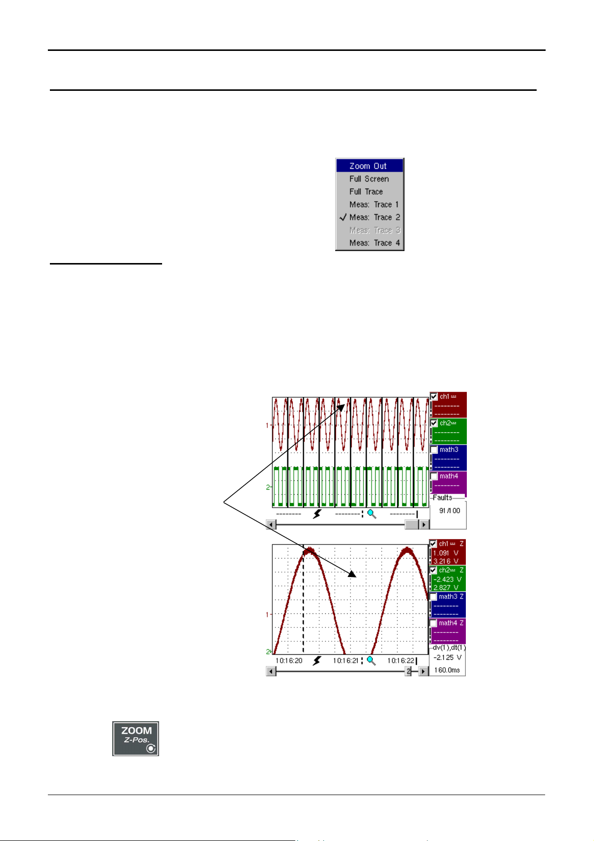
Recorder Mode - Display
Fault 5 is displayed in full screen mode and has
Recorder Mode (cont’d)
Menu accessible
from display area
Zoom creation in
Fault Capture mode
Case 1
Like in “Oscilloscope” mode, the menu concerning the display can be opened
directly by clicking with the right key of the mouse in the display area.
This menu, as well as the functions of the proposed options, are identical to
those in “Oscilloscope” mode.
Draw a rectangle around the part you wish to zoom in on with the left key of
the mouse. The screen displays, with a vertical zoom, the fault on which you
began the rectangle.
been vertically magnified
Fault 5 is
magnified.
To return to a normal display (10 faults displayed on the screen), select
“Disable zoom” in the menu,
Disabling the horizontal zoom with the zoom key allows the user to
return to a screen displaying the ten faults, but the vertical zoom
remains enabled.
VI - 94 Two-channel digital oscilloscopes, 60 MHz or 100 MHz
Page 95

Recorder Mode - Display
A zoom frame is
Recorder Mode (cont’d)
Case 2
The horizontal zoom is enabled, the screen displays the captured fault which
has been selected :
drawn.
On the displayed fault, it is possible to vertically zoom delimitating a zone with
the mouse.
Fault capture mode: the horizontal zoom is enabled.
A single fault is displayed on the screen.
As in the first case, select “disable zoom” in the menu above to disable the
zoom. The screen returns to the initial “10 faults on the screen” display.
Disabling the horizontal zoom with the zoom key allows the user to
return to a screen displaying the ten faults, but the vertical zoom
remains enabled.
A vertical zoom is applied to the area
containing the fault.
Two-channel digital oscilloscopes, 60 MHz and 100 MHz VI - 95
Page 96

Recorder Mode (cont’d)
)
)
)
Recorder Mode - « Vertical » Menu
The "VERT" Menu
(∗
(∗
(∗
(∗)
This menu is identical to that described in “Oscilloscope” mode.
(∗∗)
(∗) Functions only accessible in
"Advanced" mode.
(∗∗) The DC coupling is the only
option in “Recorder” mode.
See §. Description, p. 65.
V - 96 Two-channel digital oscilloscopes, 60 MHz or 100 MHz
Page 97

Recorder Mode - “Trigger” Menu
triggering
division
hysteresis is
applied to prevent
Recorder Mode (cont’d)
The "TRIG" Menu
Triggering
Selection of trigger type and level on each channel. Triggering takes place if a
condition described by a line of the “Trigger” table is verified.
This trigger level must be present in the display area.
Source
Level 1
Level 2
Trigger type
The Pretrig is
monitored for
each type of
trigger.
Indicates the channel number.
The main trigger threshold level can be set using the mouse.
The auxiliary trigger threshold level can be set using the mouse. This tab is
enabled only if external trigger type is selected.
Trigger levels are entered into the current value display area after modification.
Fine adjustment is possible.
This tab indicates each channel’s trigger type. Recorder mode enables several
conditions to be monitored at the same time.
“No trigger”: if all the channels are in this mode, the device records indefinitely.
•
“Lower than”: triggering takes
place when the signal drops
below the threshold.
•
“Lower/higher than”: triggering
takes place when the signal
drops below or rises above the
threshold.
•
“Higher than”: triggering takes
threshold
threshold
higher
triggering
triggering
place when the signal rises
above the threshold.
threshold
triggering
lower
lower
higher
ill-timed triggers.
Two-channel digital oscilloscopes, 60 MHz or 100 MHz VI - 97
A half-
•
“Outside window”: triggering
takes place when the signal goes
outside the window defined by
the two thresholds.
thresholds
triggering:
the signal goes
outside the
window
Page 98

Recorder Mode (cont’d)
Recorder Mode - “Trigger” Menu
Start deferred
Authorised on
Example
- Channel 1 is set with a 1.36V “higher than” trigger.
- Math 3 and 4 do not wait for a trigger.
- Channel 2 is set with an “outside” type trigger.
- Channel 1 and 2 lines are highlighted: they wait for a trigger.
Outside trigger symbol for channel 2
Toggle through the trigger conditions for the different channels
Deferred start offers the possibility of starting up an acquisition at a date and
time chosen by the user.
This option can be related to the previous trigger conditions.
This tab allows the user to validate – or not – delayed triggering.
• If the symbol “” is displayed, delayed triggering has been validated.
• If there is no symbol, delayed triggering has not been validated.
Use the mouse to validate or unvalidate the tab.
• When deferred start has been validated, the user can no longer make an
acquisition in recorder mode. He/she may, however, use the other modes
(oscilloscope, analyser) as desired.
If the user wishes to make an acquisition in recorder mode, he/she must:
- either unvalidate delayed start-up,
- or wait until the delayed start-up acquisition begins.
using the keys shown opposite.
• At the time the acquisition is set to start (deferred start time), the instrument
must be in operation and the user must have enabled recorder mode.
Date/Time
Example
Different scroll boxes allow the user to set the date and time he/she wishes the
acquisition to commence.
Use the mouse to scroll.
Deferred start: the acquisition will commence on 26 January 2005 at 17:44.
The red clock symbol shows the user that delayed start-up is enabled.
Deferred start-up symbol and time
VI - 98 Two-channel digital oscilloscopes, 60 MHz and 100 MHz
Page 99
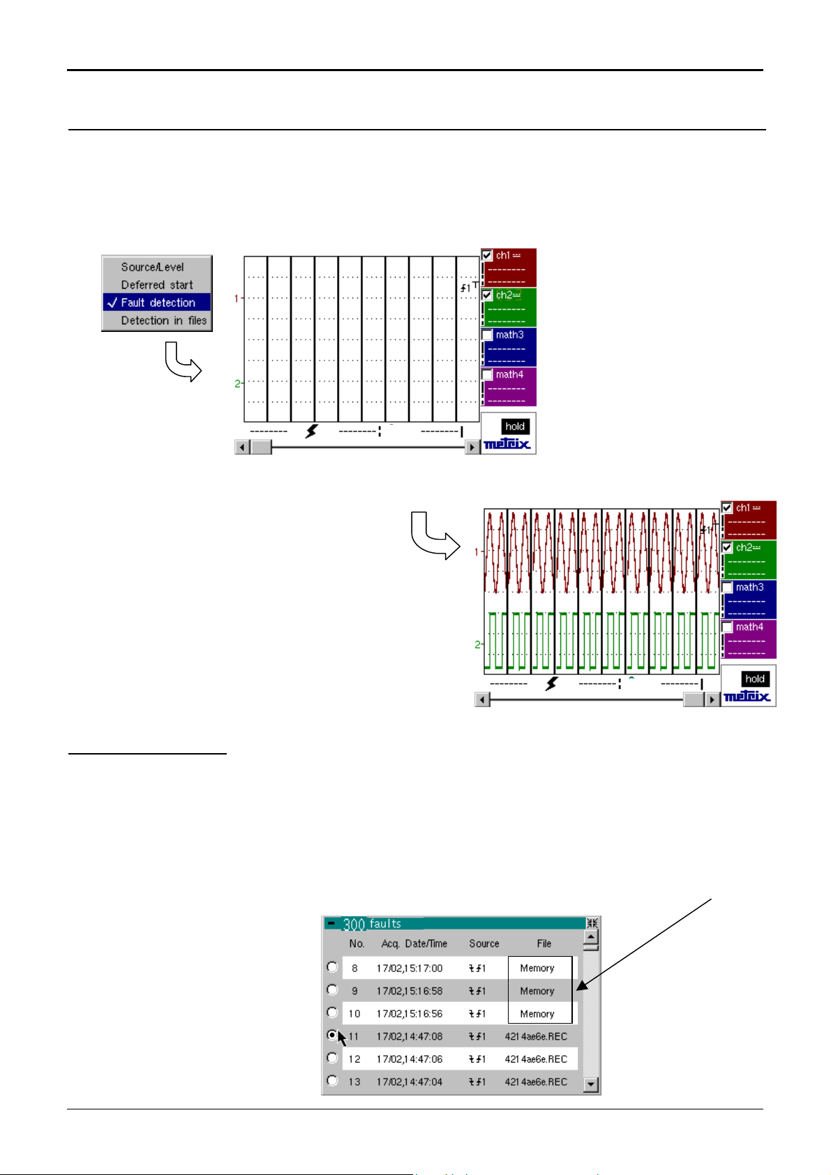
Recorder Mode - “Trigger” Menu
Recorder Mode (cont’d)
Fault capture
Example
The fault capture mode allows 100 recordings of 500 samples to be made
around the trigger point.
These 10 recordings will be displayed on the screen. Each recording is
separated by a solid vertical line. They are recorded in volatile memory.
The fault capture mode is selected:
the screen is divided into 10 sections.
Display after an acquisition in fault
capture mode
File capture
This mode is similar to fault capture mode:
-
It carries out several series of 100 recordings of 500 samples.
-
Each series of 100 recordings is stored in a file in the memory (.REC).
- The number of total recordings that may be made depends on the space
remaining in the memory.
If the memory is empty, it is possible to make up to 300 recordings of 500
samples (200 recordings saved in a file and 100 recordings in volatile memory),
totalling over 100,000 samples.
Two-channel digital oscilloscopes, 60 MHz or 100 MHz VI - 99
Page 100

Recorder Mode (cont’d)
Recorder Mode - “Trigger” Menu
File capture
(cont’d)
Example
•
When the memory is full, the acquisition is stopped and a message appears
on the screen “Write error/Auxiliary storage full!”. The message is
validated by selecting OK with the mouse. The user can then begin to study
the recordings.
•
They are displayed folder by folder. There is a file on the screen. A file
contains 100 recordings. Fault capture option display mode is available.
•
Use the Fault window to move from file to file (see §. Display Menu).
The acquisition can be interrupted at any time by pressing the RUN/STOP key.
The user can then study previously recorded faults.
File capture until the memory is full:
File capture acquisition is launched.
When 100 faults are captured, a file is created
with these 100 recordings.
The memory is full: the
acquisition is stopped
and a message is
displayed.
Final stage:
Message validation.
In order to access all the recorded faults, go to
Display menu Fault.
See Display Menu §. Faults.
VI - 100 Two-channel digital oscilloscopes, 60 MHz and 100 MHz
 Loading...