

Metabo W 7-115, W 7-125, W 7-115 Quick, W 7-125 Quick, W 10-125 Instructions For Use Manual
...Page 1

Made in Germany
Instruções de serviço . . . . . . .página 37
Instrucciones de manejo . . . .página 26
Mode d’emploi . . . . . . . . . . . . . .page 15
Instructions for use . . . . . . . . . .page 5
170 26 7970 - 0207
W 7-115
W 7-125
W 7-115 Quick
W 7-125 Quick
W 10-125
W 10-125 Quick
W 10-150 Quick
WE 9-125 Quick
WE 14-125 Plus
WE 14-125 VS
WE 14-150 Plus
WE 14-150 Quick
WEP 14-125 Quick
WEP 14-150 Quick
WP 7-115 Quick
WP 7-125 Quick
WPS 7-115 Quick
WPS 7-125 Quick
01_Ums_Nafta_7970_0207 18.12.2007 14:47 Uhr Seite 1
Page 2
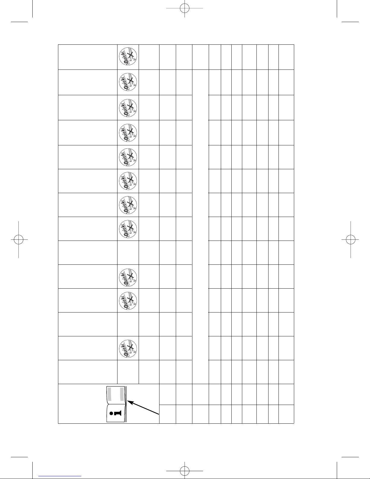
2
–– –
––––––––
D
max
mm 115 115 125 125 125 125 125 150 125 125 125 150 150 125
(in) (4 1/2) (4 1/2) (5) (5) (5) (5) (5) (6) (5) (5) (5) (6) (6) (5)
n /min 10.000 10.000 9.000 10.000 9.000 10.000 10.000 9.000 3.000- 7.000- 3.000- 6.000- 9.000
10.500
10.000 10.500 10.500 9.000
M M 14
5/8"-11 UNC
P
1
W 900 900 900 900 900 1.010 1.010 1.010 900 1.400 1.400 1.400 1.400 1.400
P
2
W
460 460 460 460 460 600 600 600 510 800 800 800 800 800
I
120V
A 8 8 8 8 8 8.5 8.5 8.5 7.5 12 12 12 12 12
a
hw
m/s
2
55555555555555
(ft/s
2
) (15) (15) (15) (15) (15) (15 (15) (15) (15) (15) (15) (15) (15) (15)
L
pA
dB(A) 84 84 84 84 84 86 86 86 84 85 85 85 85 86
L
WA
dB(A) – – – – – 99 99 99 – – – – – 99
m kg 1,8 1,8 1,8 1,8 1,8 1,8 1,8 1,8 1,9 1,9 1,9 1,9 1,9 1,9
(lbs) (4.0) (4.0) (4.0) (4.0) (4.0) (4.0) (4.0) (4.0) (4.2) (4.2) (4.2) (4.2) (4.2) (4.2)
© 2007 Metabowerke GmbH, Postfach 1229, D-72602 Nürtingen
W 7-115
W 7-115 Quick
WP 7-115 Quick
WPS 7-115 Quick
W 7-125
WP 7-125 Quick
WPS 7-125 Quick
W 10-125 Quick
W 10-125
WE 9-125 Quick
WE 14-125 Plus
WE 14-150 Plus
WE 14-150 Quick
WEP 14-150 Quick
WEP 14-125 Quick
W 10-150 Quick
W 7-125 Quick
15
WE 14-125 VS
TC
electronic
VTC
electronic
VTC
electronic
VTC
electronic
VC
electronic
TC
electronic
01_Ums_Nafta_7970_0207 18.12.2007 14:47 Uhr Seite 2
Page 3
3
11
14
10
12 13
5
1
2
3
4
8
9
WP...
WPS...
89
WEP...
6
7
01_Ums_Nafta_7970_0207 18.12.2007 14:47 Uhr Seite 3
Page 4
4
b
a
c
d
e f
f f
h i j
k l
m
g
n
o
5": 55139
6": 55140
See section 9 and 12.5 for proper installation.
Voir les sections 9 et 12.5 pour effectuer l’installation.
Ver puntos 9 y 12.5 para la correcta instalación.
Consultar as secções 9 e 12.5 para uma instalação apropriada.
01_Ums_Nafta_7970_0207 18.12.2007 14:47 Uhr Seite 4
Page 5

Contents
1 Proper Use
2 General Safety Rules
3 Specific Safety Rules
4 Functional Description
5 Special Product Features
6 Assembly, Initial Use
7 Operation, Switching On/Off
8 Operation, Setting Speed
(depending on equipment)
9 Operation, Fitting Tools
9.1 Fitting cutting and grinding discs
9.2 Securing/releasing the Quick
clamping nut (11): For Type 27
grinding wheel use only
9.3 Securing/releasing the
clamping nut (12):
For Type 1 cut-off wheels OR
Type 27 grinding wheels
10 Maintenance
11 Troubleshooting
12 Accessories
12.1 Removing the wheel guard
12.2 Fitting the hand guard
12.3 Fitting the backing pad and sanding
discs
12.4 Fitting the wire brush
12.5 Fitting the cup-grinding wheel with
wheel guard
12.6 Fitting the cutt-off wheel guard
13 Repairs
14 Environmental Protection
15 Technical Specifications
1 Proper Use
Equipped with the appropriate accessories,
Metabo angle grinders are suitable for cutting,
grinding, sanding with a backing pad and
brushing metal, concrete, stone and similar
materials in dry operating conditions.
Saw discs, saw chains or similar parts must not
be used under any circumstances.
The operator bears sole responsibility for any
damage caused by inappropriate use.
The generally recognised accident prevention
regulations and the accompanying Safety
Instructions must be observed.
2 General Safety Rules
1 WARNING! Read and understand all
instructions.
Failure to follow all instructions listed below may
result in electric shock, fire and/or serious
personal injury.
SAVE THESE INSTRUCTIONS.
2 Work Area
2.1 Keep your work area clean and well lit.
Cluttered benches and dark areas invite
accidents.
2.2 Do not operate power tools in explosive
atmospheres, such as in the presence of
flammable liquids, gases, or dust. Power tools
create sparks which may ignite the dust or fumes.
2.3 Keep bystanders, children, and visitors
away while operating a power tool. Distractions
can cause you to lose control.
3 Electrical Safety
3.1 Grounded tools must be plugged into an
outlet properly installed and grounded in
accordance with all codes and ordinances.
Never remove the grounding prong or modify
the plug in any way. Do not use any adapter
plugs. Check with a qualified electrician if you
are in doubt as to whether the outlet is
properly grounded. If the tools should
electrically malfunction or break down, grounding
provides a low-resistance path to carry electricity
away from the user.
Applicable only to Class I (grounded) tools.
3.2 Double insulated tools are equipped with
a polarized plug (one blade is wider than the
other).This plug will fit in a polarized outlet
only one way. If the plug does not fit fully in
the outlet, reverse the plug. If it still does not
fit, contact a qualified electrician to install a
Instruction for use
Dear Customer,
Many thanks for the confidence you have shown in us with the purchase of your new Metabo power tool.
Every Metabo power tool is carefully tested and is subjected to the strict quality controls of the Metabo
Quality Assurance section. However, the service life of any power tool is to a great degree dependent on
yourself as the user. Please read and understand the information contained in these Operating
Instructions and the accompanying documents. The more care you exercise in handling your Metabo
power tool, the longer will be the reliable service it provides for you.
5
ENGLISH
02_ENG_Nafta_7970_0207 18.12.2007 14:49 Uhr Seite 5
Page 6
polarized outlet. Do not change the plug in
any way. Double insulation eliminates the
need for the three-wire grounded power cord and
grounded power supply system.
Applicable only to Class II (double insulated) tools.
3.3 Avoid body contact with grounded
surfaces such as pipes, radiators, ranges and
refrigerators. There is an increased risk of
electric shock if your body is grounded.
3.4 Don’t expose power tools to rain or wet
conditions. Water entering a power tool will
increase the risk of electric shock.
3.5 Do not abuse the cord. Never use the cord
to carry the tools or pull the plug from an
outlet. Keep cord away from heat, oil, sharp
edges or moving parts. Replace damaged
cords immediately. Damaged cords increase the
risk of electric shock.
3.6 When operating a power tool outside, use
an outdoor extension cord marked
"W-A" or "W". These cords are rated for outdoor
use and reduce the risk of electric shock.
4 Personal Safety
4.1 Stay alert, watch what you are doing and
use common sense when operating a power
tool. Do not use tool while tired or under the
influence of drugs, alcohol or medication. A
moment of inattention when operating power tools
may result in serious personal injury.
4.2 Dress properly. Do not wear loose
clothing or jewelry. Contain long hair. Keep
your hair, clothing and gloves away from
moving parts. Loose clothes, jewelry or long hair
can be caught in moving parts.
4.3 Avoid accidental starting. Be sure switch
is off before plugging in. Carrying tools with
your finger on the switch or plugging in tools that
have the switch on invites accidents.
4.4 Remove adjusting keys or wrenches
before turning the tool on. A wrench or a key
that is left attached to a rotating part of the tool
may result in personal injury.
4.5 Do not overreach. Keep proper footing
and balance at all times. Proper footing and
balance enable better control of the tool in
unexpected situations.
4.6 Use safety equipment. Always wear eye
protection. Dust mask, non-skid safety shoes,
hard hat or hearing protection must be used for
appropriate conditions.
5. Tool Use and Care
5.1 Use clamps or other practical way to
secure and support the workpiece to a
stable platform. Holding the work by hand or
against your body is unstable and may lead to
loss of control.
5.2 Do not force tool. Use the correct tool for
your application. The correct tool will do the job
better and safer at the rate for which it is
designed.
5.3 Do not use tool if switch does not turn it
on or off. Any tool that cannot be controlled with
the switch is dangerous and must be repaired.
5.4 Disconnect the plug from the power
source before making any adjustments,
changing accessories, or storing the tool.
Such preventive safety measures reduce the risk
of starting the tool accidentally.
5.5 Store idle tools out of reach of children
and other untrained persons. Tools are
dangerous in the hands of untrained users.
5.6 Maintain tools with care. Keep cutting
tools sharp and clean. Properly maintained tools
with sharp cutting edges are less likely to bind
and are easier to control.
5.7 Check for misalignment or binding of
moving parts, breakage of parts, and any
other condition that may affect the tool's
operation. If damaged, have the tool serviced
before using. Many accidents are caused by
poorly maintained tools.
5.8 Use only accessories that are
recommended by the manufacturer for your
model. Accessories that may be suitable for one
tool may become hazardous when used on
another tool.
6 SERVICE
6.1 Tool service must be performed only by
qualified repair personnel. Service or
maintenance performed by unqualified personnel
could result in a risk of injury.
6.2
When servicing a tool, use only identical
replacement parts. Follow instructions in the
Maintenance section of this manual. Use of
unauthorized parts or failure to follow
Maintenance instructions may create a risk of
electric shock or injury.
3 Specific Safety Rules
Always use proper guard with grinding wheel.
A guard protects operator from broken wheel
fragments.
Accessories must be rated for at least the
speed recommended on the tool warning
label.
Wheels and other accessories running over rated
speed can fly apart and cause injury. Use at least
"max. 80 m/s".
Hold tool by insulated gripping surfaces when
performing an operation where the cutting
tool may contact hidden wiring or its own
cord.
ENGLISH
6
02_ENG_Nafta_7970_0207 18.12.2007 14:49 Uhr Seite 6
Page 7
Contact with a"live" wire will make exposed metal
parts of the tool "live" and shock the operator.
Pay particular attention to the
parts of the text marked with this
symbol for your own safety and
the protection of your power tool.
Always wear eye goggles and hearing protection.
Use other available protective equipment such as
protective gloves, suitable protective work
clothing and helmet.
Before using the angle grinder, install the side
handle (5) and always keep both hands on the
tool at all times during use.
During machining, of metals
in particular, conductive dust
can form deposits inside the
machine. This can lead to the
transfer of electrical energy onto the machine
housing. This can mean a temporary danger of
electric shocks. This is why it is necessary when
the machine is running to blow compressed air
through the rear ventilation slots of the machine
regularly, frequently and thoroughly. Here, the
machine must be held firmly.
It is recommended to use a stationary extraction
system and to place a ground fault circuit
interrupter (GFCI) downstream.
If the angle grinder is deactivated by the GFCI
circuit interrupter, the angle grinder must be
checked and cleaned. Cleaning the motor, see
Maintenance.
The dust generated during operation is often
injurious to health (e.g. when processing oak and
beech woods, stone or paintwork which may
contain lead or other harmful materials). This dust
must not be allowed to penetrate the body. Use
dust-extraction equipment as well as wearing a
suitable dust mask.
Remove any accumulations of dust thoroughly,
using a suitable vacuum cleaner.
Dust can be explosive!
Materials which generate hazardous dusts or
vapours during processing (e.g. asbestos) should
not be used.
Ensure that sparks produced during work do not
constitute a risk to the user or other personnel
and are not able to ignite inflammable
substances. Endangered areas must be protected
with flame-resistant covers. Make sure that firerisk areas are always provided with suitable fire
extinguishers.
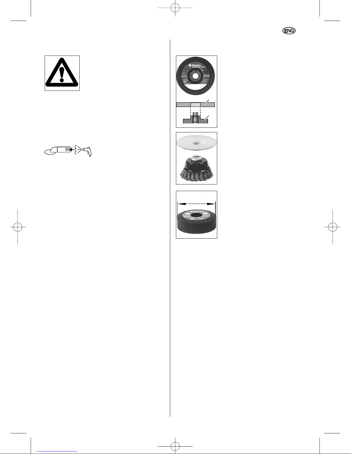
Ensure that the accessories used always fulfil
the following minimum requirements.
Respect the maximum
grinding-disc diameter (please
see Technical Specifications).
The diameter of the central
hole in the grinding disc (3)
must fit the inner flange (10)
without any play. Do not use
any adapters or reducers.
The permitted speed n
max
must
correspond at least to the
no-load speed for the power
tool (please see Technical
Specifications).
Use at least "max. 45 m/s".
Carry out a test run after every tool change,
ensuring that you are holding the angle grinder
firmly with both hands.
Hold the angle grinder away from your body.
Ensure that there is no-one present in the area at
risk. Run the angle grinder for approximately
30 seconds.
The angle grinder runs on for approx. 5 seconds
after switch-off.
Observe the information and instructions provided
by the tool or accessory manufacturer.
Do not contaminate discs with grease or subject
them to impact.
Damaged, eccentric or vibrating tools should not
be used.
Never use cutting discs for grinding purposes.
Cutting discs must not be subjected to any lateral
pressure. During cutting or grinding operation,
always work with the wheel guard (4) fitted.
Use tools in dry operating conditions only.
Do not attempt to touch the moving tool - risk of
injury.
Ensure that no damage is caused to gas or water
pipes, electrical cables and weight-bearing walls
(statics).
max. 80 mm
3
10
7
ENGLISH
02_ENG_Nafta_7970_0207 18.12.2007 14:49 Uhr Seite 7
Page 8

When using the power tool outdoors, an FI safety
switch with a maximum tripping current of 30 mA
must be connected on the incoming line side.
Angle grinder in continuous operation: To avoid
the possibility of unintentional start-up: always
turn off the switch when the plug is removed from
the socket or if an interruption to the power supply
has occurred.
Use elastic cushioning layers, if they are provided
with the coated abrasive and if they are called for.
If using threaded hole discs, ensure that the
thread in the disc is long enough for the
spindle.
Hold the work piece securely in place.
Ensure that ventilation openings are kept clear
when working in dusty conditions. If it should
become necessary to clear dust, first disconnect
the tool from the mains supply (use non metallic
objects) and avoid damaging internal parts.
Abrasive wheels shall be stored and handled with
care in accordance with manufacturer`s
instructions.
If operating the power tool in damp locations is
unavoidable, a Ground Fault Circuit Interrupter
must be used to supply the power to your tool.
Electrician’s rubber gloves and footwear will
further enhance your personal safety.
When using grinding wheel attachments, the
guard must always be attached to the tool and
positioned for maximum safety, so the least
amount of wheel is exposed from the side the tool
is being operated.
Grinding wheels or any other accessory must
have a maximum safe operation speed greater
than the “no load RPM” marked on the tool´s
nameplate.
Always use auxiliary handle for maximum
control over torque reaction or kick-back.
Operation of the grinder without the side handle
could cause loss of control of the grinder,
resulting in possible serious personal injury.
Before using a grinder or installing a new
wheel, inspect the grinding wheel for chips
and cracks. Remove bad wheels immediately.
Run the tool at no load for one minute, holding
the tool in the direction away from people.
Wheels with flaws will normaly break apart during
this time.
Carefully handle both the tool and individual
grinding wheels to avoid chipping or cracking.
Install a new wheel if tool is dropped while
grinding. Do not use a wheel that may be
damaged. Fragments from a wheel that bursts
during operation will fly away at great velocity
possibly striking you or bystanders.
Warning! Some dust created by power sanding,
sawing, grinding, drilling, and other construction
activities contains chemicals known to cause
cancer, birth defects or other reproductive harm.
Some examples of these chemicals are:
– Lead from lead-based paints,
– Crystalline silica from bricks and cement and
other masonry products, and
– Arsenic and cromium from chemically treated
lumber.
Your risk from these exposures varies, depending
on how often you do this type of work. To reduce
your exposure to these chemicals: work in a well
ventilated area, and work with approved safety
equipment, such as dust masks that are specially
designed to filter out microscopic particles.
Read operation instructions
Wear safety goggles
If the safety clutch is tripped, switch the angle
grinder off immediately and remedy the fault.
Do not use this tool with “woodcarving” blades.
Use of “woodcarving” blades can cause kickback
resulting in loss of control and possible serious
injury.
A damaged or cracked side handle must be
replaced. Never operate a machine with a
defective side handle.
Symbols on the tool:
Class II Construction
V volts
A amperes
Hz hertz
.../min revolutions per minute
~ alternating current
n0 no load speed
The „C“ and „US“ indicators adjacent to
the CSA Mark signify that the product
has been evaluated to the applicable
CSA and ANSI/UL Standards, for use
in Canada and the U.S., respectively.
ENGLISH
8
02_ENG_Nafta_7970_0207 18.12.2007 14:49 Uhr Seite 8
Page 9
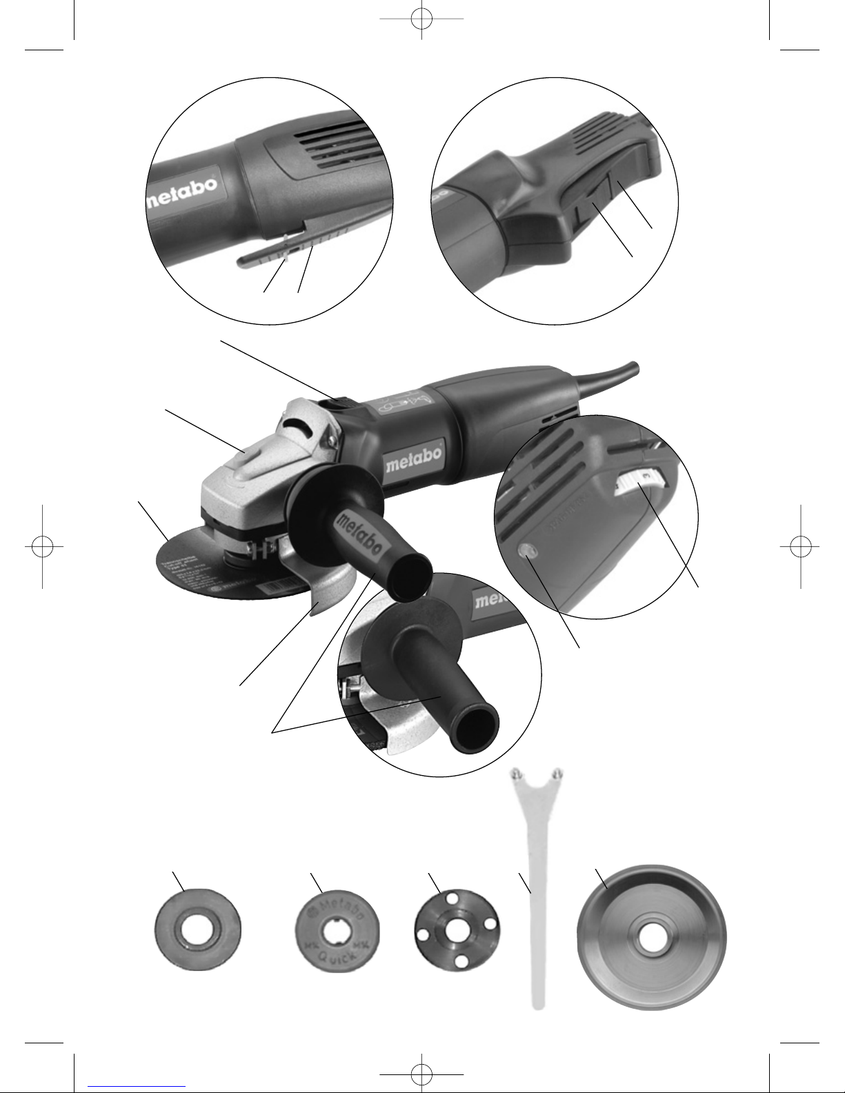
4 Functional Description
Refer to illustrations on page 3
(Please fold out).
1* Slide-switch (locking)
2 Spindle-lock button
3* Grinding disc
4 Wheel guard
5* Side handle / Side handle with vibration
damping
6* Electronic system indicator (VTC, TC only)
7* Knurled wheel for setting speed (VC, VTC)
8 Switch loc
9 Switch trigger
10* Inner flange
11* Quick clamping nut
or alternative
12* Clamping nut with
13* Pin spanner
14* Inner flange (for type 27 wheels 6" diameter)
*depending on equipment
5 Special Product Features
Metabo S-automatic safety clutch
If the tooling jams, the torque
of the machine will be
restricted. As the torque is still
very high always hold the
machine with both hands on
the handles and stand safely,
and concentrate on your work.
Marathon-Motor
The dust-protected Metabo
Marathon-Motor with its
Metabo winding-protection grid
and powder-coated coil
winding ensures up to 50%
longer service life.
Wheel guard
The wheel guard requires no tools for adjustment.
This allows it to be adjusted for a variety of
applications in a matter of seconds.
Auto-stop carbon brushes
When the auto-stop carbon brushes wear down to
a predetermined level the power tool is
automatically switched off, thus ruling out the
possibility of damage to the armature.
Additional side handle with vibration damping
(depending on scope of supply):
For comfortable work in continuous operation.
VC/VTC/TC electronic speed-control system
(depending on equipment)
This electronic control system ensures the correct
grinding speed for the relevant material (VC/VTC)
and maintains close to a constant speed, even
under load (VC/VTC/TC).
The Vario-Tacho-Constamatic (VTC)/ TachoConstamatic (TC) electronic system also features
starting-current limitation, electronicallycontrolled, smooth start-up, coil-temperature
monitoring and an electronic restart safety device.
Refer to the Technical Specifications for the
equipment level for your specific angle grinder.
6 Assembly, Initial Use
Before initial use, check that the mains
voltage and mains frequency stated on
the rating plate match the figures for
your own mains supply.
Fit side-handle
For reasons of safety, always fit the side
handle (5) to the right or left-hand side
of the angle grinder before commencing
work.
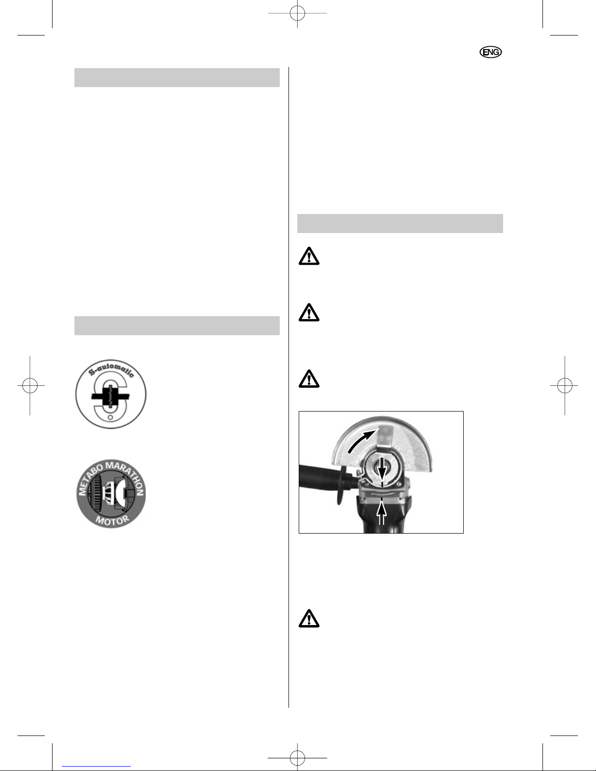
Fit wheel guard
(before working with the grinding disc)
Use correct guard for type of wheel
being used. See sections 12.4 and 12.5
for cup wheel guard and cut-off wheel
guard.
Remove the clamping nut (12) or the Quick
clamping nut (11) and the inner flange (10) from
the spindle. When fitting the wheel guard (4) to
the angle grinder, ensure that the notch on the
wheel guard coincides with the corresponding
marking on the tool itself.
Turn the wheel guard so that the closed
area is towards the operator.
Connect to mains supply.
With VTC, TC electronic system (depending on
equipment):
The red electronic system indicator (6) lights up
briefly when the mains connection is made, thus
indicating standby mode.
9
ENGLISH
02_ENG_Nafta_7970_0207 18.12.2007 14:49 Uhr Seite 9
Page 10
7 Operation, Switching On/Off
Always guide the machine with both
hands!
First switch on, then apply the tool to
the work piece!
It must be avoided that the machine
draws in additional dust and shavings.
When switching the machine on and off,
keep it away from dust deposits.
After switching off the machine, only
place it down when the motor has come
to a standstill.
In the case of VTC, TC electronic control:
the red electronic signal indicator (6) comes on
briefly when the machine is switched on.
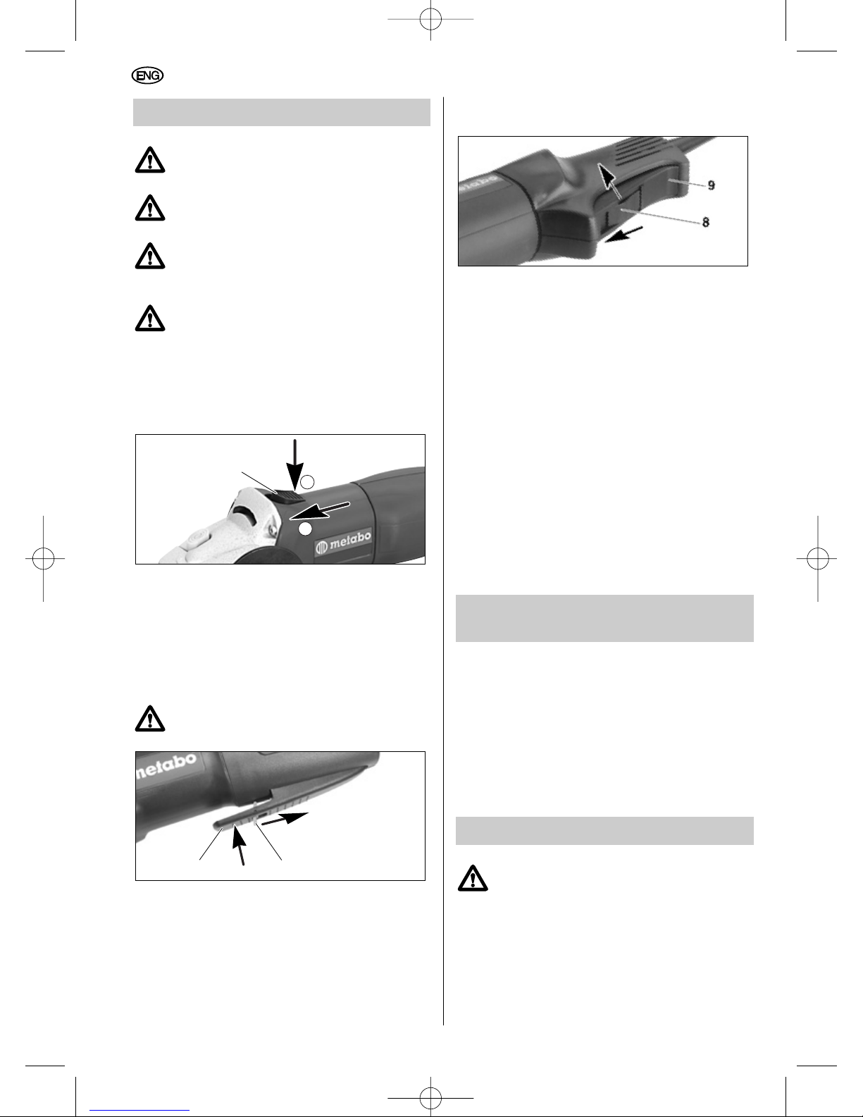
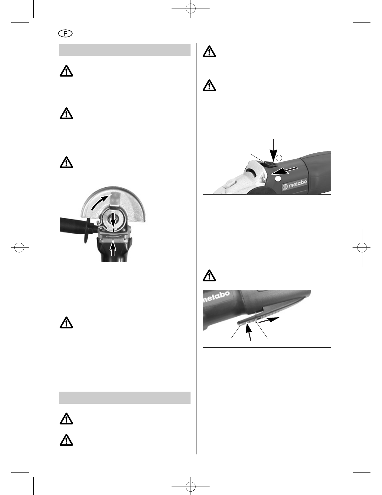
Machines with slide-switch (1):
(Machines with the designation W... or WE...)
Switching on: slide the slide-switch (1) forward
until it engages.
Switching off: press the rear end of the slideswitch.
Machines with switch lock
(Safety switch because it cannot be locked):
(Machines with the designation WEP...)
Do not carry or suspend the machine
by the trigger switch (9).
Switching on: slide the switch lock (8) in the
direction of the arrow and press the switch
trigger (9).
Switching off: Release the switch trigger (9).
Tools with switch trigger (9):
(Machines with the designation WP... or WPS...)
Switching on: slide the switch lock (8) in the
direction of the arrow and press the switch trigger
(9).
Switching off: Release the switch trigger (9).
Continuous operation:
(Machines with the designation WP...)
Switch on the angle grinder and slide the switch
lock (8) forward until it engages.
Switching off continuous operation:
Briefly press the switch trigger (9) and release.
Restart safety device
(only with VTC/TC electronic system):
If the mains connection is made with the angle
grinder still switched on or if the power supply is
restored after an interruption, the angle grinder
will refuse to start. The red electronic system
indicator (6) flashes. Switch angle grinder off and
then on again.
8 Operation, Setting Speed
(depending on equipment)
Set the recommended speed with the knurled
wheel (7).
Grinding disc, cutting disc, cup grinding
wheel: high speed setting
Brush: middle speed setting
Surface dressing discs: low to middle speed
setting
Apply only light pressure to the tool when working
at low speeds.
9 Operation, Fitting Tools
Before any tool changing operation,
always remove the plug from the mains
supply socket and check that the angle
grinder is switched off and that the
spindle has come to a halt.
Locking the spindle
Press in the spindle-lock button (2) and turn the
spindle by hand until the spindle-lock button can
be felt to engage in position.
9 8
1
0
I
ENGLISH
10
02_ENG_Nafta_7970_0207 18.12.2007 14:49 Uhr Seite 10
Page 11

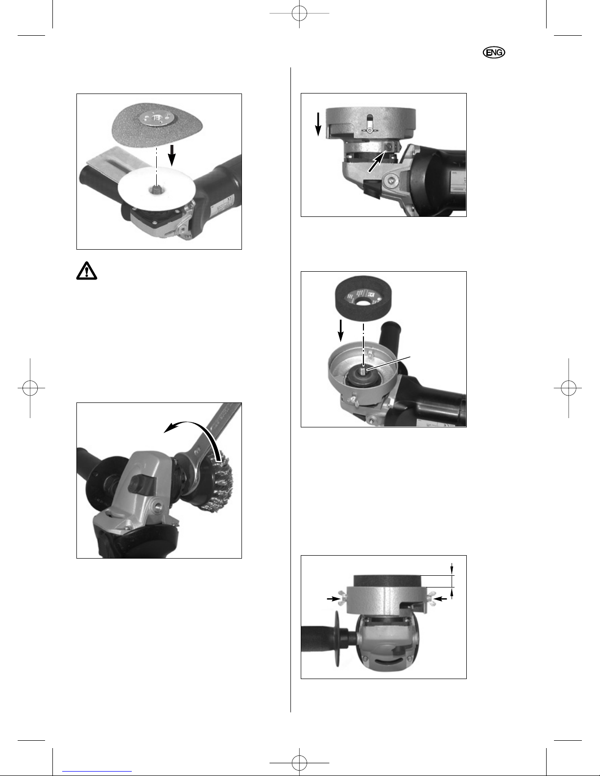
9.1 Fitting cutting and grinding discs
Locate the inner flange (10) for type 1 cutting
discs, (10) for type 27 wheels 5” diameter or
smaller, or (14) for type 27 wheels 6” diameter, as
illustrated, ensuring that the inner flange cannot
turn on the spindle.
Position the cutting disc or the grinding disc on the
inner flange, as illustrated, ensuring that the cutting
disc is supported evenly by the inner flange. When
cutting, the sheet metal flange on the cutter disc
should be resting on the inner flange.
9.2 Securing/releasing the Quick
clamping nut (11): For Type 27
grinding wheel use only
Securing
For tools which are thicker than 8 mm
(5/16”) in the clamping area, use the
clamping nut (12) with the pin spanner
(13) instead of the Quick clamping
nut (11).
Fit the Quick clamping nut (11) in the grooves on
the spindle as illustrated. Lock the spindle in
position. Turn the Quick clamping nut (11)
clockwise by hand until tight. Tighten the Quick
clamping nut by turning the grinding wheel firmly
in a clockwise direction.
Releasing
After switch-off, the angle grinder runs on for
approx. 5 seconds. Press the spindle-lock button
(2) shortly before the grinding tool comes to a
final halt and the Quick clamping nut releases
itself.
Using the spindle-lock button (2) to stop
the spindle is only permitted if the
Quick clamping nut is in use!
Screw the Quick clamping nut off.
9.3 Securing/releasing the
clamping nut (12):
For Type 1 cut-off wheels OR
Type 27 grinding wheels
Securing
For wheels thinner than 3/16" turn clamping nut
(12) onto the spindle with the raised collar away
from the wheel so that the wheel can be clamped
securely. Tighten securely using spanner wrench
(13).
For wheels 3/16" and thicker, turn clamping nut
(12) onto spindle with the raised collar facing the
wheel so that the collar engages the ID of the
wheel. Tighten securely using spanner wrench
(13).
12
12
12
14
11
10
10
14
11
ENGLISH
02_ENG_Nafta_7970_0207 18.12.2007 14:49 Uhr Seite 11
Page 12
Lock the spindle in position. Fit the pin spanner
(13) onto the clamping nut (12) and turn
clockwise to tighten.
Releasing
Lock the spindle in position, slacken off the
clamping nut with the pin spanner (13) and
screw off.
10 Maintenance
Remove the plug from the mains supply socket
before undertaking any maintenance work.
Motor cleaning: blow compressed air through the
rear ventilation slots of the machine regularly,
frequently and thoroughly. Here, the machine
must be held firmly.
The auto-stop carbon brushes must only be
replaced in an accredited workshop. Have checks
and maintenance carried out by Metabo
Authorized Services.
11 Troubleshooting
With VTC, TC electronic system:
electronic system indicator (6) lights up.
The coil temperature is too high. Allow the angle
grinder to run under no-load conditions until the
indicator display is extinguished.
12 Accessories
Use original Metabo accessories only.
Your Metabo dealer will supply you with any
accessories you may require.
To assist in selecting the correct accessories,
make sure that you take a note of the exact
model of your tool for your dealer.
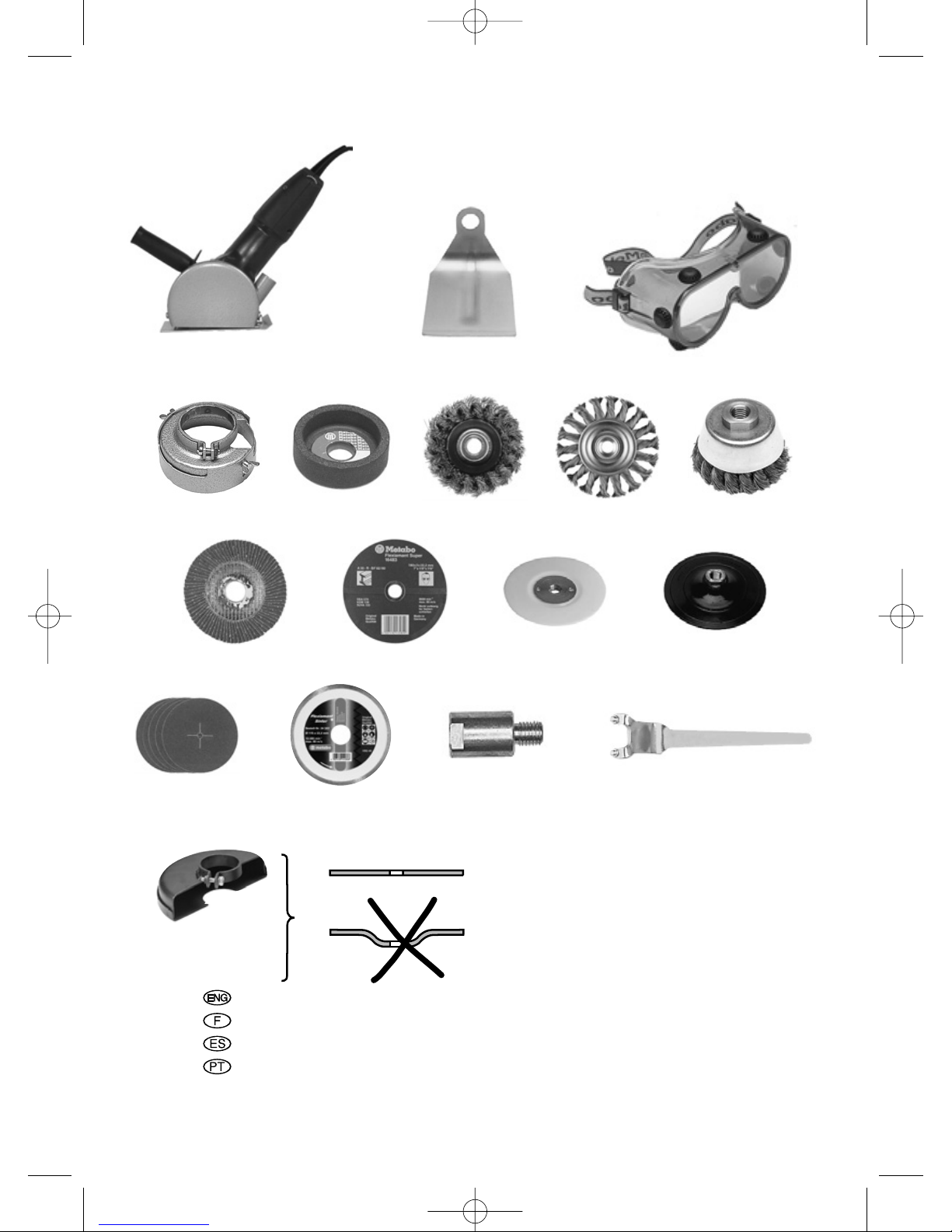
Refer to illustrations on page 4:
a Wheel guard with cutting and chasing guide
for processing stone
b Hand guard
c Safety goggles
d Cup-grinding wheel guard
e Cup-grinding wheel for surface smoothing
f Wire brushes
g Lamellar surface dressing discs
h Cutting and grinding discs
i Backing pads
j Cling-fit backing pads
k Sanding discs
l Diamond cutting blade
m Extension for working with backing pads
n Pin spanner (offset)
o cutt-off wheel guard
12.1 Removing the wheel guard
12.2 Fitting the hand guard
(working with backing pad and sanding
disc or brush)
Remove the tool, wheel guard and side-handle,
as necessary.
Fit the hand guard (b) over the threaded part of
the handle (5). Adjust the hand guard and fit to
the angle grinder along with the side-handle.
b
1
2
3
12
13
ENGLISH
12
02_ENG_Nafta_7970_0207 18.12.2007 14:49 Uhr Seite 12
Page 13
12.3 Fitting the backing pad and sanding
disc
Use only the clamping nut supplied
along with the backing pad.
Locate the backing pad (i) on the spindle, as
illustrated. Mount the sanding disc (k) with the
backing pad clamping nut supplied. Lock the
spindle in position. Tighten the sanding disc and
backing pad by turning clockwise by hand.
Slacken off manually or with the pin spanner (13),
as necessary.
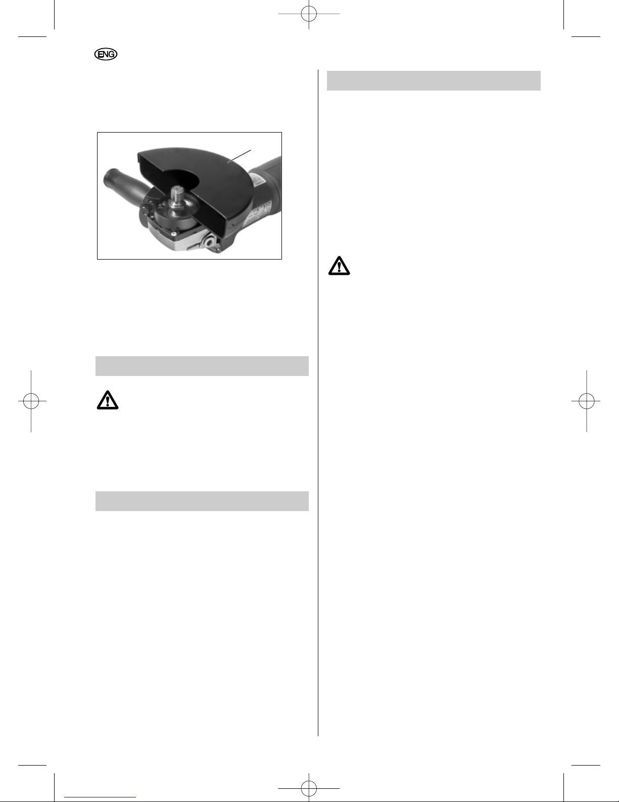
12.4 Fitting the wire brush
Fit the hand guard.
Remove the wheel guard (4). Lock the spindle in
position. Mount the wire brush (f) and tighten with
the 22 mm AF open-ended spanner (7/8").
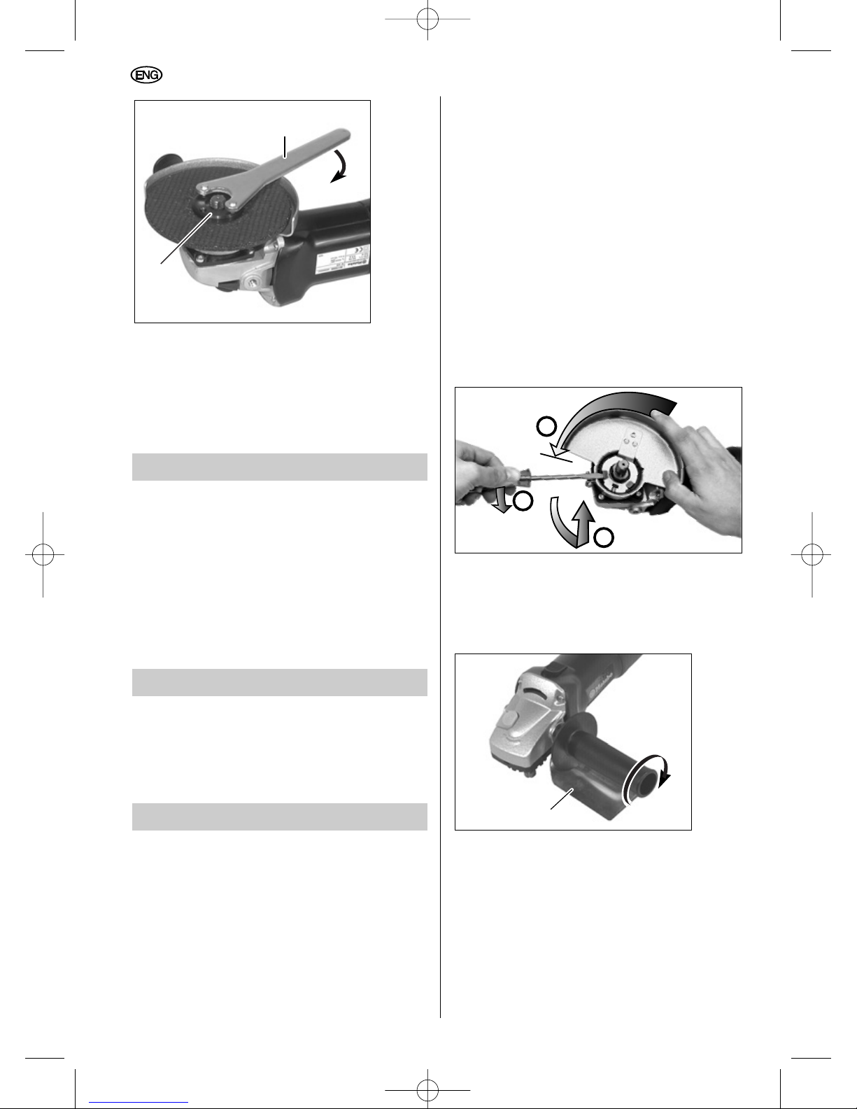
12.5 Fitting the cup-grinding wheel with
wheel guard
Remove the wheel guard (4). Fit the cup-grinding
wheel guard to the angle grinder, turning it on in
the direction indicated by the arrow until fully in
position. Use a screwdriver to tighten the screw.
Locate the inner flange (10) on the spindle,
ensuring that the flange cannot turn on the
spindle. Position the cup-grinding wheel so that it
rests evenly on the inner flange.
Screw the clamping nut (12) or the Quick
clamping nut (11) onto the spindle. Lock the
spindle in position. Secure the cup-grinding wheel
with the clamping nut (12) or the Quick clamping
nut (11).
Use the offset pin spanner (n) if the clamping nut
(12) is being used.
Set the cup-grinding wheel/wheel guard
projection as required (approx. 0.5 - 1 cm/
10
13
ENGLISH
02_ENG_Nafta_7970_0207 18.12.2007 14:49 Uhr Seite 13
Page 14
0.2" - 0.4"). Slacken off the two wing screws and
adjust the wheel guard evenly upwards or down.
Retighten wing screws.
12.6 Fitting the cut-off wheel guard
Remove the wheel guard (4). Fit the cut-off wheel
guard (o) by aligning the 3 raised retention nibs
on the guard with the slots on the flange. Push
the guard on fully, then rotate the guard and
position the guard between the operator and
the wheel. Tighten the clamping screw to secure
the guard in position.
13 Repairs
Repairs to power tools must be carried
out by a qualified electrician only.
Any Metabo power tools in need of repair can be
sent to one of the addresses listed on the secondlast page.
Please send the tool for repair with a brief
description of the fault identified.
14 Environmental Protection
Metabo packaging is 100% suitable for recycling.
Power tools and accessories at the end of their
service life still contain large amounts of valuable
raw materials and plastics which can likewise be
fed back into a recycling process.
As the dust generated during grinding/cutting may
contain harmful materials, do not dispose of it
along with domestic waste but ensure it is taken
to a collection point for special waste for proper
disposal.
These Operating Instructions are printed on paper
produced in a chlorine-free bleaching process.
15 Technical Specifications
Notes on the details on page 2.
We reserve the right to undertake modifications to
reflect technical advances.
D
max
= maximum grinding disc diameter
n = no-load speed
M = spindle thread
P
1
= rated input
P
2
= output power
I
120V
= current at 120 V
a
hw
= typically rated acceleration in the
hand-arm area
Typical A-rated acoustic level:
L
pA
= acoustic pressure level
L
WA
= acoustic power level
Wear ear protectors!
m = weight
Measured values established according to
EN 50144.
The stated technical specifications are subject to
tolerances (as specified in the respective current
standards).
o
ENGLISH
14
02_ENG_Nafta_7970_0207 18.12.2007 14:49 Uhr Seite 14
Page 15

Table des matières
1 Utilisation en conformité
2 Règles de sécurité générales
3 Consignes de sécurité spéciales
4 Vue d'ensemble
5 Caractéristiques spécifiques du produit
6 Mise en service
7 Mise en marche et arrêt
8 Réglage de la vitesse (selon l'équipement)
9 Montage des outils
9.1 Mise en place des meules de
tronçonnage et d'ébarbage
9.2 Fixation/Desserrage de l’écrou de
serrage Quick (11) : à utiliser avec la
meule boisseau de type 27 uniqument
9.3 Fixation/Desserrage de l’écrou de
serrage Quick (12) : à utiliser avec la
meule de tronçonnage de type 1 OU la
meule boisseau de type 27 uniquement
10 Maintenance
11 Dépannage
12 Accessoires
12.1 Déposer le protecteur de sécurité
12.2 Mise en place du protège-main
12.3 Mise en place du plateau à poncer
et du disque abrasif
12.4 Mise en place de la brosse
métallique à fils d'acier
12.5 Mise en place de la meule boisseau
droite et du protecteur de sécurité
12.6 Fixation du protecteur à découpe
13 Réparations
14 Protection de l'environnement
15 Caractéristiques techniques
1 Utilisation en conformité
Equipées des accessoires d'origine Metabo
correspondants, les meuleuses d'angle
conviennent au tronçonnage, au meulage, au
ponçage avec plateau à poncer et au brossage
des métaux, du béton, de la pierre et matériaux
similaires, sans utilisation d'eau.
Ne jamais utiliser de lame de coupe, de chaîne
de coupe ou outil semblabe.
En cas de dommages résultant d'une utilisation
non conforme, seule la responsabilité du
propriétaire est engagée.
Il convient de respecter les prescriptions
généralement reconnues en matière de
prévention des accidents ainsi que les consignes
de sécurité jointes.
2 Règles de sécurité générales
1 AVERTISSEMENT! Vous devez lire et
comprendre toutes les instructions.
Le non-respect, même partiel, des instructions ciaprès entraîne un risque de choc électrique,
d'incendie et/ou de blessures graves.
CONSERVEZ CES INSTRUCTIONS.
2 Aire de travail
2.1 Veillez à ce que l’aire de travail soit propre
et bien éclairée. Le désordre et le manque de
lumière favorisent les accidents.
2.2 N'utilisez pas d’outils électriques dans
une atmosphère explosive, par exemple en
présence de liquides, de gaz ou de poussières
inflammables. Les outils électriques créent des
étincelles qui pourraient enflammer les
poussières ou les vapeurs.
2.3 Tenez à distance les curieux, les enfants
et les visiteurs pendant que vous travaillez
avec un outil électrique. Ils pourraient vous
distraire et vous faire faire une fausse manœuvre.
3 Sécurité électrique
3.1 Les outils mis à la terre doivent être
branchés dans une prise de courant
correctement installée et mise à la terre
conformément à tous les codes et règlements
pertinents. Ne modifiez jamais la fiche de
quelque façon que ce soit, par exemple en
enlevant la broche de mise à terre. N'utilisez
pas d'adaptateur de fiche. Si vous n’êtes pas
certain que la prise de courant est
correctement mise à la terre, adressez-vous à
un électricien qualifié. En cas de défaillance ou
de défectuosité électrique de l'outil, une mise à la
terre offre un trajet de faible résistance à
l'électricité qui autrement risquerait de traverser
l'utilisateur.
Mode d'emploi
Cher client,
Nous vous remercions de la confiance que vous nous avez témoignée par l'achat de votre nouvel
appareillage électrique Metabo. Chaque outillage électrique Metabo est soigneusement testé et subit les
contrôles de qualité particulièrement sévères du programme d'assurance-qualité Metabo. Toutefois, la
longévité d'un outillage électrique dépend grandement de vous. Veuillez donc tenir compte des
informations du présent mode d'emploi ainsi que des documents joints. La longévité et la fiabilité de
votre outillage électrique Metabo seront d'autant plus élevées que vous le traiterez avec soin.
15
FRANÇAIS
03_FR_Nafta_7970_0207 18.12.2007 14:50 Uhr Seite 15
Page 16

S'applique aux outils de classe I (mis à la terre)
seulement.
3.2 Les outils à double isolation sont équipés
d’une fiche polarisée (une des lames est plus
large que l’autre), qui ne peut se brancher que
d’une seule façon dans une prise polarisée. Si
la fiche n’entre pas parfaitement dans la prise,
inversez sa position ; si elle n’entre toujours
pas bien, demandez à un électricien qualifié
d’installer une prise de courant polarisée.
Ne modifiez pas la fiche de l’outil. La double
isolation élimine le besoin d’un cordon
d’alimentation à trois fils avec mise à la terre ainsi
que d’une prise de courant mise à la terre.
S’applique aux outils de classe II seulement.
3.3 Evitez tout contact corporel avec des
surfaces mises à la terre (tuyauterie,
radiateurs, cuisinières, réfrigérateurs, etc.).
Le risque de choc électrique est plus grand si
votre corps est en contact avec la terre.
3.4 N’exposez pas les outils électriques à la
pluie ou à l’eau. La présence d’eau dans un outil
électrique augmente le risque de choc électrique.
Cette consigne est facultative pour les outils
étanches à l’eau ou à l’épreuve de
l'éclaboussement.
3.5 Ne maltraitez pas le cordon. Ne
transportez pas l’outil par son cordon et ne
débranchez pas la fiche en tirant sur le
cordon. N’exposez pas le cordon à la chaleur,
à des huiles, à des arêtes vives ou à des
pièces en mouvement. Remplacez
immédiatement un cordon endommagé. Un
cordon endommagé augmente le risque de choc
électrique.
3.6 Lorsque vous utilisez un outil électrique à
l’extérieur, employez un prolongateur pour
l'extérieur marqué « W-A » ou « W ». Ces
cordons sont faits pour être utilisés à l’extérieur et
réduisent le risque de choc électrique.
4 Sécurité des personnes
4.1 Restez alerte, concentrez-vous sur votre
travail et faites preuve de jugement. N’utilisez
pas un outil électrique si vous êtes fatigué ou
sous l’influence de drogues, d’alcool ou de
médicaments. Un instant d'inattention suffit pour
entraîner des blessures graves.
4.2 Habillez-vous convenablement. Ne portez
ni vêtements flottants ni bijoux. Confinez les
cheveux longs. N’approchez jamais les
cheveux, les vêtements ou les gants des
pièces en mouvement. Des vêtements flottants,
des bijoux ou des cheveux longs risquent d’être
happés par des pièces en mouvement.
4.3 Méfiez-vous d’un démarrage accidentel.
Avant de brancher l’outil, assurez-vous que
son interrupteur est sur ARRÊT. Le fait de
transporter un outil avec le doigt sur la détente ou
de brancher un outil dont l’interrupteur est en
position MARCHE peut mener tout droit à un
accident.
4.4 Enlevez les clés de réglage ou de serrage
avant de démarrer l’outil. Une clé laissée dans
une pièce tournante de l’outil peut provoquer des
blessures.
4.5 Ne vous penchez pas trop en avant.
Maintenez un bon appui et restez en équilibre
en tout temps. Un bonne stabilité vous permet
de mieux réagir à une situation inattendue.
4.6 Utilisez des accessoires de sécurité.
Portez toujours des lunettes ou une visière.
Selon les conditions, portez aussi un masque
antipoussière, des bottes de sécurité
antidérapantes, un casque protecteur et/ou un
appareil antibruit.
5. Utilisation et entretien des outils
5.1 Immobilisez le matériau sur une surface
stable au moyen de brides ou de toute autre
façon adéquate. Le fait de tenir la pièce avec la
main ou contre votre corps offre une stabilité
insuffisante et peut amener un dérapage de l’outil.
5.2 Ne forcez pas l'outil. Utilisez l’outil
approprié à la tâche. L’outil correct fonctionne
mieux et de façon plus sécuritaire. Respectez
aussi la vitesse de travail qui lui est propre.
5.3 N’utilisez pas un outil si son interrupteur
est bloqué. Un outil que vous ne pouvez pas
commander par son interrupteur est dangereux et
doit être réparé.
5.4 Débranchez la fiche de l’outil avant
d’effectuer un réglage, de changer
d’accessoire ou de ranger l’outil. De telles
mesures préventives de sécurité réduisent le
risque de démarrage accidentel de l’outil.
5.5 Rangez les outils hors de la portée des
enfants et d’autres personnes
inexpérimentées. Les outils sont dangereux
dans les mains d’utilisateurs novices.
5.6 Prenez soin de bien entretenir les outils.
Les outils de coupe doivent être toujours bien
affûtés et propres. Des outils bien entretenus,
dont les arêtes sont bien tranchantes, sont moins
susceptibles de coincer et plus faciles à diriger.
5.7 Soyez attentif à tout désalignement ou
coincement des pièces en mouvement, à tout
bris ou à toute autre condition préjudiciable
au bon fonctionnement de l’outil. Si vous
constatez qu’un outil est endommagé, faitesle réparer avant de vous en servir. De
nombreux accidents sont causés par des outils
en mauvais état.
5.8 N’utilisez que des accessoires que le
fabricant recommande pour votre modèle
d’outil. Certains accessoires peuvent convenir à
un outil, mais être dangereux avec un autre.
16
FRANÇAIS
03_FR_Nafta_7970_0207 18.12.2007 14:50 Uhr Seite 16
Page 17

6 RÉPARATION
6.1 La réparation des outils électriques doit
être confiée à un réparateur qualifié. L’entretien
ou la réparation d’un outil électrique par un
amateur peut avoir des conséquences graves.
6.2 Pour la réparation d’un outil, n’employez
que des pièces de rechange d’origine.
Suivez les directives données à la section
« Réparation » de ce manuel. L’emploi de
pièces non autorisées ou le non-respect des
instructions d’entretien peut créer un risque de
choc électrique ou de blessures.
3 Consignes de
sécurité spéciales
Avant d'utiliser l'outillage électrique, lisez
attentivement et intégralement les consignes de
sécurité (cahier rouge) et le présent mode
d'emploi. Conservez tous les documents fournis
avec l'outillage électrique. Si vous prêtez votre
outillage électrique, veillez à toujours joindre
également cette documentation.
Pour votre propre protection et
pour celle de votre outillage
électrique, tenez compte des
passages repérés par ce
symbole !
Munissez-vous toujours de lunettes de protection
et d’une protection auditive. Utilisez également
tout autre équipement de sécurité des personnes,
comme des gants, des vêtements de protection
adéquats et un casque.
Avant l'utilisation de la meuleuse d'angle, adaptez
la poignée (5) et guidez toujours la meuleuse
d'angle avec les deux mains.
En cours de travail, et surtout
s’il s’agit de métaux, il est
possible que des poussières
conductrices s’accumulent
dans la machine. Il se peut alors qu’il y ait un
transfert d’énergie électrique sur le corps de
machine. Ainsi, par moment il pourra y avoir un
risque d’électrocution. Pour cette raison, il est
impératif de nettoyer la machine régulièrement,
fréquemment et soigneusement, en soufflant de
l’air comprimé à travers les fentes d’aération à
l’arrière pendant que la machine tourne. Veiller à
bien maintenir la machine pendant ce temps.
Il est recommandé d’installer un système
d’aspiration fixe et de prévoir un disjoncteur à
courant de défaut (FI).
Lorsque la meuleuse d’angle est arrêtée par son
interrupteur de protection FI, la meuleuse d’angle
doit être vérifiée et nettoyée. Voir nettoyage du
moteur sous maintenance.
La poussière qui se dégage pendant les travaux
est souvent nocive pour la santé (par ex. dans le
cas du chêne et du hêtre ou de couches de
peinture susceptibles de contenir du plomb ou
autres substances toxiques). Cette poussière ne
doit pas être inhalée. Utilisez un dispositif
d'aspiration et portez en supplément un masque
antipoussières approprié !
Eliminez soigneusement la poussière qui se
dépose, par ex. en l'aspirant à l'aide d'un
aspirateur approprié ! La poussière peut
provoquer des risques d'explosion.
Le meulage de matériaux produisant des
poussières ou des vapeurs nocives pour la santé
(p. ex. l'amiante) est formellement interdit.
Veillez à ce que les étincelles produites lors de
l’utilisation ne provoquent aucun risque, par ex.
celui d’atteindre l’utilisateur ou d’autres
personnes, ou d’incendie de substances
inflammables. Toute zone à risque doit être
protégée par des bâches difficilement
inflammables. Tenez un moyen d’extinction
adéquat à votre disposition pour travailler dans
une zone à risque d’incendie.
Utiliser toujours des pièces de rechange
répondant aux exigences minimales
suivantes.
Respecter le diamètre maximal
de meule (voir caractéristiques
techniques). Utiliser des
meules de type "max 80 m/s".
Le diamètre intérieur du disque
abrasif (3) doit s'ajuster sans
jeu sur le flasque d’appui (10).
Ne pas utiliser d'adaptateurs
ou de réducteurs.
La vitesse admissible n
max
doit correspondre au minimum
à la vitesse à vide de
l'outillage électrique (voir
caractéristiques techniques).
Utiliser au minimum des outils
de type "max 45 m/s".
Après chaque changement d'outil, procéder à un
essai de fonctionnement en tenant fermement la
meuleuse d'angle des deux mains.
max. 80 mm
3
10
17
FRANÇAIS
03_FR_Nafta_7970_0207 18.12.2007 14:50 Uhr Seite 17
Page 18

Tenir la meuleuse d'angle éloignée du corps.
Veiller à ce que personne ne se trouve dans la
zone de danger. Faire marcher la meuleuse
d'angle pendant environ 30 secondes.
Après sa mise hors circuit, la meuleuse d'angle
continue à fonctionner pendant encore environ
5 secondes.
Tenir compte des indications du fabricant de l'outil
ou de l'accessoire !
Protéger les meules contre la graisse et les
chocs !
Ne pas utiliser d'outils endommagés, présentant
un défaut de circularité ou générant des
vibrations.
Ne jamais utiliser des meules de tronçonnage
pour des travaux de meulage ! Les meules de
tronçonnage ne doivent en aucun cas être
soumises à une pression latérale. Utiliser
systématiquement le protecteur de sécurité (4)
lors des travaux de tronçonnage ou de
meulage !
Les outils doivent toujours être secs lors de leur
utilisation !
Ne pas toucher l'outil en mouvement, risque de
blessures !
Eviter de provoquer des dommages au niveau de
conduites de gaz ou d'eau, de câbles électriques
et de murs porteurs (pour des questions de
stabilité).
En cas d'utilisation de l'outillage électrique en
plein air, monter en amont un disjoncteur
différentiel avec un courant de déclenchement de
30 mA max !
Mise en service discontinue de la meuleuse
d´angle: Pour éviter tout redémarrage
intempestif : Déverrouiller systématiquement la
gâchette lorsque la fiche est débranchée du
secteur ou en cas de coupure de courant.
Utiliser des intercalaires élastiques s'ils sont mis à
disposition avec le matériau de ponçage et s'ils
sont nécessaires.
En cas d'utilisation de disques taraudés veillez à
ce que le filet dans le disque soit assez long pour
loger la longueur de la broche.
Bien fixer l'outil.
Veuillez faire en sorte que les orifices d'aération
soient dégagés en cas de travaux créant de la
poussière. Si l'enlèvement de la poussière devait
être nécessaire, débranchez en premier l'outil
électrique du réseau d'alimentation électrique
(utiliser des objets non métalliques) et évitez
d'endommager les pièces internes.
Les disques de meuleuse doivent être conservés
et manipulés soigneusement selon les indications
du fabricant.
S’il est inévitable de faire fonctionner l’outil
électrique dans des endroits humides, utilisez un
disjoncteur de fuite à la terre. Pour plus de
sécurité, portez des chaussures et des gants en
caoutchouc d’électricien.
Lors de l’utilisation d’accessoires, le capot doit
toujours être installé et positionné de sorte à
assurer une sécurité maximum, la surface de
meule exposée devant être la plus réduite
possible du côté de l’utilisateur.
Les meules (ou tout autre accessoire) doivent
avoir une vitesse de fonctionnement maximum
(garantissant une sécurité optimale) supérieure
au nombre de tours/minute hors charge indiqué
sur la plaque signalétique.
Utilisez toujours la poignée auxiliaire pour
contrer au maximum le couple de réaction ou
l’effet de recul. Manier la meuleuse sans
poignée peut entraîner une perte de contrôle et
des blessures graves.
Avant d’utiliser la meuleuse ou d’installer une
nouvelle meule, vérifiez l’absence de brèches
et de fissures sur la meule. Changez
immédiatement toute meule défectueuse.
Faites fonctionner l’outil hors charge pendant
une minute, en prenant garde à ce que l’outil
ne soit pas orienté vers les personnes se
trouvant à proximité. Les meules défectueuses
doivent normalement se partager au cours de
cette opération.
Manipulez l’outil et les meules avec
précaution pour éviter les brèches et les
fissures. Si vous faites chuter l’outil en cours
de fonctionnement, installez une nouvelle
meule. N’utilisez jamais de meule
endommagée. Les fragments produits par une
meule se désintégrant en cours de
fonctionnement sont projetés à très grande
vitesse et risquent de vous atteindre ou
d’atteindre les personnes se trouvant à proximité.
Attention ! Les poussières générées par les
travaux de meulage, sciage, affûtage, perçage et
autres travaux de construction contiennent des
substances chimiques pouvant provoquer des
cancers, des malformations à la naissance voire
une infertilité. Voici quelques exemples de ces
substances chimiques :
– le plomb (dans les peintures à base de plomb),
– la silice cristallisée (dans les briques, le ciment
et autres matériaux de maçonnerie),
– l’arsenic et le chrome (dans le bois de
charpente traité chimiquement).
Les risques encourus dépendent de la fréquence
à laquelle vous effectuez tel ou tel type de travail.
Pour réduire votre exposition à ces substances
chimiques, travaillez dans un endroit ventilé et
portez un équipement de sécurité homologué,
comme des masques anti-poussière
spécialement conçus pour filtrer les particules
microscopiques.
18
FRANÇAIS
03_FR_Nafta_7970_0207 18.12.2007 14:50 Uhr Seite 18
Page 19

Lire le mode d'emploi
Porter des lunettes de protection
En cas de déclenchement du débrayage de
sécurité, mettre immédiatement la meuleuse
d'angle hors circuit et remédier au dysfonctionnement.
Ne pas utiliser de lames "à sculpter" avec cet
outil. L'utilisation de lames "à sculpter" peut
générer un effet de recul se traduisant par une
perte de contrôle et pouvant ainsi être à l'origine
de blessures graves.
Une poignée avant endommagée ou craquelée
doit être remplacée. N'utilisez pas la machine si la
poignée avant est défectueuse.
Symboles sur l'outil:
Construction de classe II
V volts
A ampères
Hz hertz
.../min révolutions par minute
~ courant alternatif
n0 vitesse à vide
Les mentions "C" et "US" ajoutées au
label CSA signifient qu'il s'agit d'un
produit conforme aux normes CSA et
ANSI/UL, applicables pour un emploi
du produit respectivement au Canada
et aux Etats-Unis.
4 Vue d'ensemble
Voir page 3 (déplier le document).
1* Curseur de commutation (verrouillable)
2 Bouton de blocage de l'arbre portemeule
3* Meule
4 Protecteur de sécurité
5* Poignée avant / poignée avant avec
amortisseur de vibrations
6* Signaux électroniques lumineux
(uniquement VTC, TC)
7* Molette de réglage de la vitesse (VC, VTC)
8 Dispositif de blocage de la gâchette
9 Gâchette
10* Flasque d'appui
11* Ecrou de serrage Quick
ou
12* Ecrou de serrage avec
13* Clé à ergots
14* Flasque d’appui
(pour les meules de type 27, diamètre 6")
*selon l'équipement
5 Caractéristiques
spécifiques du produit
Débrayage de sécurité Metabo S-automatic
Si l'outil interchangeable reste
coincé ou accroché, la
transmission de la force vers le
moteur est limitée. Comme
dans ce cas, on rencontre des
forces élevées, il faut
systématiquement saisir la
machine des deux mains aux
poignées prévues à cet effet, veiller à bien se
camper sur ses jambes et à se concentrer sur
son travail.
Moteur Marathon
Le moteur Marathon, protégé
contre la poussière, garantit
une longévité jusqu'à 50 %
plus élevée grâce à la grille
Metabo de protection du
bobinage et aux bobines
inductrices époxydées.
Protecteur de sécurité
Le réglage sans outils du protecteur de sécurité
permet une adaptation ultrarapide aux différentes
applications.
Balais autorupteurs
Lorsque les balais autorupteurs sont usés,
l'outillage s'arrête automatiquement, ce qui évite
les risques d'endommagement du collecteur.
Poignée avant supplémentaire avec
amortisseur de vibrations (suivant version) :
Assure le confort pour travaux en continu.
Système électronique VC/VTC/TC
(selon l'équipement)
Le système électronique permet un meulage
adapté au type de matériau (VC/VTC) et une
vitesse pratiquement constante, même en charge
(VC/VTC/TC).
Le système électronique Vario-TachoConstamatic VTC / Tacho-Constamatic TC
dispose en outre d'une limitation du courant de
démarrage, d'un démarrage électronique
progressif, d'une surveillance de la température
du bobinage ainsi que d'une protection
électronique de redémarrage.
Pour connaître l'équipement de votre outillage
électrique, reportez-vous aux caractéristiques
techniques.
19
FRANÇAIS
03_FR_Nafta_7970_0207 18.12.2007 14:50 Uhr Seite 19
Page 20
6 Mise en service
Avant la mise en service, s'assurer que
la tension secteur et la fréquence
indiquées sur la plaquette signalétique
correspondent à celles du courant que
vous utilisez.
Montage de la poignée
Pour des raisons de sécurité, il est
impératif de toujours monter la poignée
(5) du côté droit ou du côté gauche de
la meuleuse d'angle avant de
commencer à travailler.
Montage du protecteur de sécurité
(pour les travaux avec des meules)
Utiliser le protecteur correspondant au
type de meule utilisé. Voir les sections
12.4 et 12.5 pour les protecteurs
circulaires et les protecteurs à découpe.
Retirer l'écrou de serrage (12) ou l'écrou de
serrage Quick (11) et le flasque d'appui (10) de
l'arbre porte-meule.
Lors de la mise en place du protecteur de
sécurité (4) sur la meuleuse d'angle, veiller à ce
que l'encoche sur le protecteur coïncide avec le
repère sur la meuleuse d'angle.
Tourner le protecteur de sécurité de
sorte que la partie fermée soit tournée
vers l'utilisateur !
Brancher la fiche secteur.
Dans le cas du système électronique VTC, TC
(selon l'équipement) :
Le signal électronique lumineux rouge (6)
s'allume brièvement lorsque l'on branche la fiche
secteur dans la prise de courant, indiquant ainsi
que la machine est prête à fonctionner.
7 Mise en marche et arrêt
Toujours tenir la machine par les deux
mains en travaillant !
Toujours mettre sous tension avant de
positionner la machine sur la pièce !
Veiller à éviter que la machine aspire
des poussières et copeaux
supplémentaires. Lors de la mise en
route et de l’arrêt de la machine, la tenir
loin des dépôts de poussière.
Après l’avoir arrêtée, ne poser la
machine qu’une fois que le moteur a
cessé de tourner.
Dans le cas du système électronique VTC,TC :
le signal électronique lumineux rouge (6) s'allume
brièvement lors de la mise en marche.
Machines avec curseur de commutation (1) :
(Machines portant la désignation W... ou WE...)
Mise en marche : pousser le curseur de
commutation (1) vers l'avant jusqu'à ce qu'il
s'enclenche.
Arrêt : appuyer sur l'extrémité arrière du curseur
de commutation.
Outils munis d'une sécurité de transport
(Dispositif de sécurité, la machine ne pouvant
pas être bloquée) :
(Machines portant la désignation WEP…)
Ne pas utiliser pas la gâchette (9) pour
porter ou suspendre l'outil.
Mise en marche : Faire coulisser le dispositif de
blocage de la gâchette (8) dans le sens de la
flèche et enfoncer la gâchette (9).
Arrêt : Relâcher la gâchette (9).
Machines avec gâchette (9) :
(Machines portant la désignation WP... ou WPS...)
9 8
1
0
I
20
FRANÇAIS
03_FR_Nafta_7970_0207 18.12.2007 14:50 Uhr Seite 20
Page 21

Mise en marche : Faire coulisser le dispositif de
blocage de la gâchette (8) dans le sens de la
flèche et enfoncer la gâchette (9).
Arrêt : Relâcher la gâchette (9).
Blocage en position de marche:
(Machines portant la désignation WP...)
Mettre en marche la meuleuse d'angle et faire
coulisser le dispositif de blocage de la gâchette
(8) vers l'avant jusqu'à ce qu'il s'enclenche.
Désactivation du blocage en position de
marche : Enfoncer brièvement la gâchette (9) et
la relâcher.
Protection de remise en marche (uniquement
en cas de système électronique VTC/TC) :
La meuleuse d’angle ne démarre pas lorsque l’on
branche la fiche dans la prise de courant et que la
machine est sur la position "Marche" ou lors du
rétablissement de la tension après une coupure
de courant. Le signal électronique lumineux rouge
(6) clignote. Arrêter et redémarrer la meuleuse
d'angle.
8 Réglage de la vitesse
(selon l'équipement)
Régler la vitesse recommandée à l'aide de la
molette de réglage (7).
Meules de tronçonnage, meules d'ébarbage,
meules boisseau, disques à jante diamantée :
vitesse élevée
Brosses : vitesse moyenne
Plateaux de ponçage : vitesse faible à moyenne
Lors des travaux à faible vitesse, n'exercer qu'une
légère pression sur l'outillage électrique.
9 Montage des outils
Avant chaque opération de
transformation, débrancher la fiche de
la prise et s’assurer que la meuleuse
d’angle est hors circuit.
Blocage de l'arbre porte-meule
Enfoncer le bouton de blocage de l'arbre portemeule (2) jusqu'à ce que le bouton s'enclenche
de manière perceptible.
9.1 Mise en place des meules de
tronçonnage et d'ébarbage
Localisez le flasque d’appui (10) pour les meules
de tronçonnage de type 1, (10) les meules de
type 27 de diamètre 5" ou moins, ou (14) pour les
meules de type 27 de diamètre 6", comme
illustré, en vous assurant que le flasque d’appui
ne peut pas tourner sur la broche.
Poser, comme indiqué sur la figure, la meule de
tronçonnage ou la meule d’ébarbage sur le
flasque d’appui. Veiller à ce que la meule repose
de manière uniforme sur le flasque d’appui. Lors
du tronçonnage, le flasque de tôle de la meule de
tronçonnage doit être appliqué sur le flasque
d’appui.
9.2 Fixation/Desserrage de l’écrou de
serrage Quick (11) : à utiliser avec la
meule boisseau de type 27 uniquement
Serrage
11
10
10
14
21
FRANÇAIS
03_FR_Nafta_7970_0207 18.12.2007 14:50 Uhr Seite 21
Page 22

Pour les outils dont l'épaisseur est
supérieure à 8 mm dans la zone de
serrage, il convient d'utiliser l'écrou de
serrage (12) avec la clé à ergots (13) à la
place de l'écrou de serrage rapide
Quick (11).
Mettre en place l'écrou de serrage Quick (11)
dans les rainures de l'arbre, comme indiqué sur la
figure. Bloquer l'arbre. Serrer à la main l'écrou de
serrage Quick (11) en le tournant dans le sens
inverse des aiguilles d'une montre. Bloquer
l'écrou de serrage Quick en tournant fortement la
meule dans le sens des aiguilles d'une montre.
Desserrage
Après l'arrêt de la meuleuse, la meule continue à
tourner pendant environ 5 secondes. Juste avant
l'arrêt de l'outil de meulage, enfoncer le bouton de
blocage de l'arbre porte-meule (2) - l'écrou de
serrage Quick se débloque.
L'arrêt de la broche au moyen du
bouton de blocage de l'arbre portemeule (2) n'est autorisé qu'en cas
d'utilisation de l'écrou de serrage
Quick !
Dévisser l'écrou de serrage Quick.
9.3 Fixation/Desserrage de l’écrou de
serrage Quick (12) : à utiliser avec la
meule de tronçonnage de type 1
OU la meule boisseau de type 27
uniquement
Fixation
Pour les meules de moins de 3/16", tournez
l’écrou de serrage (12) sur la broche avec le bord
relevé opposé à la meule de manière à pouvoir
serrer la meule en toute sécurité. Serrez à fond à
l’aide d’une clé à fourche (13).
Pour les meules de 3/16" et plus, tournez l’écrou
de serrage (12) sur la broche avec le bord relevé
orienté vers la meule de sorte que le bord pénètre
dans l’ID de la meule. Serrez à fond à l’aide d’une
clé à fourche (13).
Bloquer l'arbre porte-meule. Mettre en place la clé
à ergots (13) sur l'écrou de serrage (12) et le
serrer à fond dans le sens des aiguilles d'une
montre.
Desserrage
Bloquer l'arbre porte-meule. Débloquer l'écrou de
serrage à l'aide de la clé à ergots (13) et le
dévisser.
10 Maintenance
Avant tout travail de maintenance : débrancher la
fiche de la prise de courant !
Nettoyage du moteur : nettoyer la machine
régulièrement, fréquemment et soigneusement,
en soufflant de l’air comprimé à travers les fentes
d’aération à l’arrière. Veiller à bien maintenir la
machine pendant ce temps.
Le remplacement des balais ne peut être effectué
que par l’usine de production ou par un atelier
spécialisé. Faire effectuer les inspections et les
opérations de maintenance par le service aprèsvente Metabo.
11 Dépannage
Avec système électronique VTC,TC :
Le signal électronique lumineux (6) s'allume et
la vitesse en charge diminue.
Température trop élevée du bobinage. Faire
tourner à vide la meuleuse jusqu'à ce que le
signal électronique lumineux s'éteigne.
12 Accessoires
Utilisez exclusivement des accessoires Metabo
d'origine.
12
13
12
12
12
14
22
FRANÇAIS
03_FR_Nafta_7970_0207 18.12.2007 14:50 Uhr Seite 22
Page 23

Pour vous procurer les accessoires voulus,
veuillez vous adresser à votre revendeur.
Afin de pouvoir choisir les accessoires
parfaitement adaptés, veuillez indiquer le type
exact de votre appareillage électrique à votre
revendeur.
Voir page 4 :
a Protecteur de sécurité avec semelle
d'appui pour le tronçonnage de la pierre
b Protège-main
c Lunette protectrice
d Protecteur de sécurité pour meules
boisseau
e Meule boisseau pour le lissage de surfaces
f Brosses métalliques à fils d'acier
g Plateau abrasif à lamelles
h Meules de tronçonnage et d'ébarbage
i Plateau souple à poncer
j Plateau à poncer à agrippage velcro
k Disques abrasifs
l Disque à jante diamantée
m Rallonge pour le travail avec des plateaux à
poncer
n Clé à ergots (coudée)
o protecteur à découpe
12.1 Déposer le protecteur de sécurité
12.2 Mise en place du protège-main
(pour les travaux avec des plateaux à
poncer et des disques abrasifs ou brosses)
Le cas échéant, déposer l'outil, le protecteur de
sécurité et la poignée.
Engager le protège-main (b) sur la partie filetée
au niveau de la poignée (5). Orienter le protègemain et le monter sur la meuleuse d'angle avec la
poignée.
12.3 Mise en place du plateau à poncer et
du disque abrasif
Utiliser exclusivement l'écrou de serrage
fourni avec le plateau à poncer !
Poser le plateau à poncer (i) sur l'arbre portemeule, comme indiqué sur la figure. Visser le
disque abrasif (k) à l'aide de l'écrou de serrage
fourni. Bloquer l'arbre porte-meule. Bloquer à la
main le disque abrasif avec le plateau à poncer
en le tournant dans le sens des aiguilles d'une
montre.
Desserrage à la main ou, le cas échéant, à l'aide
de la clé à ergots (13).
12.4 Mise en place de la brosse métallique
à fils d'acier
Monter le protège-main.
Déposer le protecteur de sécurité (4). Bloquer
l'arbre porte-meule. Visser la brosse métallique à
fils d'acier (f) et la serrer à fond à l'aide d'une clé
plate de 22 mm (7/8").
b
1
2
3
23
FRANÇAIS
03_FR_Nafta_7970_0207 18.12.2007 14:50 Uhr Seite 23
Page 24

12.5 Mise en place de la meule boisseau
droite et du protecteur de sécurité
Déposer le protecteur de sécurité (4). Dans le
sens de la flèche, emmancher le protecteur pour
meule boisseau (d) jusqu'en butée sur la
meuleuse d'angle. Bloquer la vis à l'aide d'un
tournevis.
Poser le flasque d'appui (10) sur la broche. Veiller
à ce que le flasque d'appui ne puisse pas se
tordre sur la broche. Poser la meule boisseau sur
le flasque d'appui.
Visser l'écrou de serrage (12) ou l'écrou de serrage
Quick (11) sur l'arbre porte-meule. Bloquer l'arbre.
Serrer la meule boisseau à l'aide de l'écrou de
serrage (12) ou de l'écrou de serrage Quick (11).
Dans le cas de l'écrou de serrage (12), utiliser la
clé coudée à ergots (n).
Selon les besoins, régler la longueur de la partie
de la meule boisseau dépassant du protecteur de
sécurité (environ 0,5-1 cm). A cet effet, dévisser
les deux vis à ailettes et faire coulisser de
manière régulière le protecteur de sécurité vers le
haut ou vers le bas. Revisser les vis à ailettes.
12.6 Fixation du protecteur à découpe
Retirez le protecteur (4). Posez le protecteur à
découpe (o) en alignant les 3 tenons de retenue
relevés sur le protecteur avec les encoches du
flasque. Enfoncez complètement le protecteur,
puis tournez le protecteur et positionnez-le entre
l’opérateur et la meule. Serrez l’écrou de
serrage pour fixer le protecteur en position.
13 Réparations
Les réparations des outillages
électriques doivent uniquement être
réalisées par des électriciens qualifiés !
Les outillages électriques Metabo à réparer
peuvent être envoyés à l'une des adresses
indiquées à l'avant-dernière page.
Lors de l'envoi à la réparation, veuillez indiquer le
défaut constaté.
14 Protection de
l'environnement
Les emballages Metabo sont recyclables à 100 %.
Les outillages électriques et les accessoires
usagés contiennent d'importantes quantités de
matières premières et de plastiques qui peuvent
également être recyclées.
Etant donné que la poussière de meulage
produite peut contenir des substances polluantes,
il convient donc de ne pas la jeter dans une
poubelle normale, mais de la mettre en décharge
dans un site de collecte de déchets spéciaux.
Le présent mode d'emploi est imprimé sur du
papier blanchi sans chlore.
o
10
24
FRANÇAIS
03_FR_Nafta_7970_0207 18.12.2007 14:50 Uhr Seite 24
Page 25

15 Caractéristiques techniques
Explications des indications de la page 2.
Sous réserve de modifications techniques.
D
max
= Diamètre maximal de meule
n = Vitesse à vide
M = Filetage de la broche
P
1
= Puissance nominale absorbée
P
2
= Puissance utile
I
120V
= Courant sous 120 V
a
hw
= Accélération typique pondérée au
niveau de la main et du bras
Niveau acoustique A standardisé :
L
pA
= Niveau de pression acoustique
L
WA
= Niveau de puissance acoustique
Porter une protection acoustique !
m = Poids
Valeurs de mesure calculées selon EN 50144.
Les caractéristiques indiquées sont soumises à
tolérance (selon les normes en vigueur
correspondantes).
25
FRANÇAIS
03_FR_Nafta_7970_0207 18.12.2007 14:50 Uhr Seite 25
Page 26

Indice
1 Aplicación de acuerdo a la finalidad
2 Normas generales de seguridad
3 Instrucciones especiales de seguridad
4 Vista de conjunto
5 Características especiales del producto
6 Puesta en marcha
7 Conexión y desconexión
8 Ajustar el número de revoluciones
(dependiendo del equipamiento)
9 Colocación de las herramientas
9.1 Colocar los discos de tronzar y
de desbaste
9.2 Apretar / aflojar la tuerca de sujeción
rápida (11): sólo para muelas abrasivas
del tipo 27
9.3 Apretar / aflojar la tuerca de sujeción
(12): para muelas de corte del tipo 1
O muelas abrasivas del tipo 27
10 Mantenimiento
11 Eliminación de anomalías
12 Accesorios
12.1 Desmontar la caperuza protectora
12.2 Colocar la protección para las manos
12.3 Colocar el plato de apoyo y la hoja
de lijar
12.4 Colocar el cepillo de alambre
12.5 Colocar la muela de cazoleta con
caperuza de protección
12.6 Colocar la caperuza de protección de la
muela de corte
13 Reparación
14 Protección ecológica
15 Especificaciones técnicas
1 Aplicación de acuerdo
a la finalidad
Las amoladoras angulares combinadas con los
accesorios originales son aptas para tronzar, lijar
con plato de apoyo y cepillar metal, hormigón,
piedra y otros materiales similares sin aplicar
agua.
No deben utilizarse en ningún caso ni hojas ni
cadenas de sierra o herramientas similares.
El usuario será responsable exclusivo de daños
causados por una utilización en
desacuerdo con la finalidad descrita del presente
aparato. Se debe prestar estricta atención a las
prescripciones generalmente reconocidas para la
prevención de accidentes laborales y a las
instrucciones de seguridad adjuntas.
2 Normas generales de
seguridad
1 ADVERTENCIA! Asegúrese de leer y
comprender todas las instrucciones.
De no seguir todas las instrucciones indicadas a
continuación se corre el riesgo de sufrir una
descarga eléctrica, fuego y/o lesión personal
grave.
GUARDE ESTAS INSTRUCCIONES.
2 Zona de trabajo
2.1 Mantenga su zona de trabajo limpia y bien
iluminada.Los bancos desordenados y los sitios
oscuros pueden ocasionar accidentes.
2.2 No ponga en marcha herramientas
eléctricas en ambientes propensos a
explosiones, como ante la presencia de
líquidos inflamables,de gases o de polvo.
Las herramientas eléctricas generan chispas que
pueden inflamar el polvo o los gases.
2.3 Mantenga alejados a personas
circundantes, niños y visitantes cuando
ponga una herramienta eléctrica en marcha.
Las distracciones le pueden hacer perder el
control.
3 Seguridad eléctrica
3.1 Las herramientas con puesta a tierra
deben ser conectadas a un tomacorriente
instalado correctamente y puesto a tierra
conforme a la legislación vigente. Nunca retire
el terminal de puesta a tierra ni modifique la
clavija bajo ninguna circunstancia. No use
ningún tipo de adaptador de enchufe.
Consulte a un electricista profesional si no
Instrucciones de manejo
Muy estimado Señor Cliente:
Le agradecemos la confianza puesta en nosotros al adquirir su herramienta eléctrica Metabo. Toda
herramienta eléctrica Metabo es comprobada minuciosamente siendo sometida a un estricto control de
calidad por la sección de aseguramiento de calidad de Metabo. No obstante, la vida útil de una
herramienta eléctrica depende esencialmente de Vd. Por esta razón, le rogamos que preste atención a
las informaciones entregadas en el presente manual de instrucciones para el manejo y en los
documentos anexos. Cuanto más cuidadosamente maneje Vd. la herramienta eléctrica Metabo, tanto
mayor será su fiabilidad operativa y su vida útil.
26
ESPAÑOL
04_ES_Nafta_7970_0207 18.12.2007 14:52 Uhr Seite 26
Page 27

está seguro de que el tomacorriente está
puesto a tierra correctamente. Si los
componentes eléctricos de la herramienta no
funcionan bien o si la herramienta eléctrica se
avería, la puesta a tierra proporciona una vía de
baja resistencia para alejar la electricidad del
usuario.
Se debe aplicar sólo para las herramientas de la
Categoría I (con puesta a tierra).
3.2 Las herramientas doblemente aisladas
constan de una clavija polarizada (una
cuchilla es más ancha que la otra). De manera
que esta clavija se acopla únicamente de un
modo a un tomacorriente polarizado. Si la
clavija no se acopla bien en el tomacorriente,
invierta el sentido de la clavija. Si aun asi no
se acopla correctamente contacte con un
electricista profesional para instalar un
tomacorriente polarizado. No modifique la
clavija bajo ninguna circunstancia. El
aislamiento doble elimina la necesidad de un
cable de alimentación trifilar con puesta a tierra, y
asimismo elimina la necesidad de un sistema de
alimentación eléctrica con puesta a tierra.
Se debe aplicar sólo para las herramientas
(doblemente aisladas) de la Categoría II.
3.3 Evite el contacto corporal con las
superficies de puesta a tierra, tales como
tubos, radiadores, cocinas económicas y
frigoríficos. Corre un alto riesgo de sufrir una
descarga eléctrica si su cuerpo está unido a
tierra.
3.4 No exponga las herramientas eléctricas a
la lluvia ni a la humedad. La entrada de agua en
una herramienta eléctrica incrementa el riesgo de
sufrir una descarga eléctrica.
3.5 No someta el cable a esfuerzos. Nunca
use el cable para transportar la herramienta ni
tire del cable para desconectarlo del
tomacorriente. Mantenga el cable alejado del
calor, grasa, bordes afilados y de las partes
móviles. Cambie de inmediato los cables
deteriorados, pues incrementan el riesgo de sufrir
una descarga eléctrica.
3.6 Cuando ponga a funcionar la herramienta
eléctrica en el exterior, use un alargador
marcado con "W-A" o "W". Estos cables son
adecuados para su uso en el exterior y reducen
el riesgo de sufrir una descarga eléctrica.
4 Seguridad personal
4.1 Manténgase alerta, preste atención a lo
que está haciendo y use sentido común
cuando ponga a funcionar una herramienta
eléctrica. No use la herramienta cuando esté
cansado o bajo la influencia de drogas,
alcohol o medicamentos. Un momento de
descuido cuando esté usando una herramienta
eléctrica puede resultar en una lesión personal
grave.
4.2 Use la vestimenta apropiada. No use ropa
holgada ni joyas. Recójase el pelo. Mantenga
el pelo, la ropa y los guantes alejados de las
partes móviles. La ropa holgada, las joyas o el
pelo largo se pueden quedar atrapados en las
partes móviles.
4.3 Evite un arranque accidental. Asegúrese
que el interruptor está apagado antes de
conectar la herramienta. Transportar la
herramienta estando los dedos en el interruptor o
conectar la herramienta cuando el interruptor está
accionado, puede ocasionar un accidente.
4.4 Antes de accionar la herramienta, retire
las llaves y las cuñas. Una llave inglesa u otro
tipo de llave que se ha dejado fija a una parte
móvil puede provocar una lesión corporal.
4.5 No intente alcanzar lo imposible.
Mantenga en todo momento los pies bien
apoyados y el equilibrio, pues esto permite
controlar mejor la herramienta en situaciones
inesperadas.
4.6 Use equipo de seguridad. Siempre lleve
puestas unas gafas de protección. Se
recomienda utilizar máscara contra el polvo,
zapatos antideslizantes de seguridad, un casco
duro y protección para los oídos.
5. Utilización y cuidado de la herramienta
eléctrica
5.1 Use pinzas de sujeción u otros medios
prácticos para fijar y apoyar la pieza de
trabajo en una plataforma estable. Sujetar con
la mano o contra el cuerpo la pieza de trabajo
resulta inestable y puede ocasionar la pérdida del
control.
5.2 No someta la herramienta a un esfuerzo.
Use la herramienta apropiada para el trabajo
que realiza. La herramienta correcta hará el
trabajo mejor y más seguro en la utilización para
la que ha sido concebida.
5.3 No use la herramienta si no es posible
conectar y desconectar el interruptor. Toda
herramienta que no pueda ser controlada por
medio del interruptor resulta peligrosa y debe ser
reparada.
5.4 Desconecte el enchufe de la fuente de
alimentación antes de realizar cualquier tipo
de ajuste, cambiar los accesorios o guardar la
herramienta. Estas medidas preventivas de
seguridad reducen el riesgo de poner la
herramienta en marcha accidentalmente.
5.5 Guarde las herramientas que no esté
usando fuera del alcance de los niños y de las
personas no instruidas sobre su uso. Las
herramientas resultan peligrosas cuando caen en
manos de personas no instruidas sobre su uso.
5.6 Cuide las herramientas eléctricas.
Mantenga las herramientas de corte afiladas y
limpias. Las herramientas bien cuidadas, con los
27
ESPAÑOL
04_ES_Nafta_7970_0207 18.12.2007 14:52 Uhr Seite 27
Page 28

bordes afilados correctamente, son menos
propensas a obstruirse y son más fáciles de
controlar.
5.7 Inspeccione si la herramienta presenta
desajustes u obstrucciones de las partes
móviles, rotura de las partes o cualquier otro
estado que afecte el funcionamiento de la
misma. Si se avería debe de ser reparada
antes de volver a usarla. Muchos accidentes
son provocados por herramientas mal cuidadas.
5.8 Use únicamente los accesorios
recomendados por el fabricante para su
modelo. Los accesorios que son adecuados para
una herramienta pueden ser peligrosos si se
usan con otra herramienta.
6 SERVICIO DE REPARACIÓN
6.1 La reparación de la herramienta debe ser
realizada sólo por personal cualificado, pues
de lo contrario podría producirse un riesgo de
lesión.
6.2 Al reparar la herramienta, se deben usar
únicamente piezas de repuesto idénticas. Siga
las instrucciones contenidas en la sección de
Mantenimiento de este Manual. Si se usan
piezas no autorizadas o no se observan las
instrucciones de mantenimiento, se corre el
riesgo de sufrir una descarga eléctrica o una
lesión.
3 Instrucciones especiales
de seguridad
Antes de utilizar la herramienta eléctrica, léase
completa y detenidamente las instrucciones de
seguridad (cuadernillo rojo) y el manual de
instrucciones para el manejo adjuntos.Guarde
todos los documentos entregados junto con la
herramienta eléctrica y preste la herramienta
eléctrica siempre incluyendo estos documentos.
¡Sírvase prestar especial
atención a las partes del texto
marcadas mediante este
símbolo, con el fin de garantizar
su propia protección personal y
la protección de su herramienta
eléctrica!
Utilice siempre unas gafas protectoras y
protección de oídos. Utilice también otros equipos
de protección personal como guantes, ropa
protectora adecuada y casco.
Antes de utilizar la amoladora angular, coloque la
empuñadura (5) y guie siempre la herramienta
con ambas manos.
Durante el proceso de
mecanizado, especialmente
si se trata de metales, puede
depositarse polvo de gran
conductividad en el interior de la herramienta.
Este polvo puede transmitir la energía eléctrica a
la carcasa de la herramienta. Este hecho puede
ser motivo de una posible descarga eléctrica. Por
eso, es necesario limpiar con frecuencia a fondo
la herramienta estando ésta en marcha a través
de la rejilla de ventilación inferior utilizando aire a
presión. Para ello, fijar bien la herramienta.
Se recomienda el uso de una instalación de
aspiración fija y un interruptor de corriente de
defecto (FI).
Cuando se utilice el interruptor de protección FI
para desconectar la amoladora angular, ésta
debe someterse a una comprobación y limpieza
posterior. Para información acerca de la limpieza
del motor, ver el apartado de Mantenimiento.
A menudo, el polvo que se produce al trabajar
con esta herramienta es perjudicial para la salud
(por ejemplo, al trabajar con madera de encina o
haya, o bien con pinturas que pudieran contener
plomo u otras substancias nocivas). ¡Este polvo
no debe penetrar en el cuerpo humano! ¡Utilizar
siempre un equipo de aspiración de polvo y llevar
adicionalmente una máscara protectora contra el
polvo!
¡Eliminar completamente el polvo depositado,
utilizando, por ejemplo, una aspiradora de polvo
adecuada! El polvo puede ser explosivo
No deben ser tratados los materiales que durante
el tratamiento produzcan polvo y vapores nocivos
para la salud (por ejemplo, amianto).
Cuide que las chispas generadas al utilizar la
pistola no provoquen ningún peligro, p. ej. que no
alcancen al usuario, otras personas o sustancias
inflamables. Las zonas peligrosas se deben
cubrir con mantas de difícil inflamación. Tenga un
extintor adecuado al alcance cuando trabaje
cerca de zonas peligrosas.
Utilice siempre accesorios que satisfagan los
requerimientos mínimos descritos a
continuación.
Observar el diámetro máximo
del disco abrasivo (véanse las
especificaciones técnicas).
Aplicar por lo menos "máx. 80
m/s". El diámetro del taladro
del disco abrasivo (3) debe
estar ajustado a la brida de
apoyo (10) sin holguras. No
utilizar adaptadores o piezas
reductoras.
El número de revoluciones
máx. admisible debe equivaler
por lo menos al número de
revoluciones de marcha en
vacío de la herramienta
eléctrica (véanse las
especificaciones técnicas).
3
10
28
ESPAÑOL
04_ES_Nafta_7970_0207 18.12.2007 14:52 Uhr Seite 28
Page 29

Aplicar por lo menos "máx.
45 m/s".
Después de cada cambio de herramienta deberá
llevarse a cabo una marcha de prueba. Para este
efecto se debe sujetar firmemente la amoladora
angular con ambas manos.
Mantenga la amoladora angular a una distancia
prudencial de Vd. Asegúrese de que nadie se
encuentra en la zona de peligro. Deje funcionar la
amoladora angular durante unos 30 segundos.
Después de apagarse la amoladora angular, ésta
seguirá rotando por inercia unos 5 segundos
más.
¡Observar las especificaciones del fabricante de
las herramientas o piezas de accesorios!
¡Proteger los discos contra grasa y golpes!
No deben ser utilizadas las herramientas
descentradas o que produzcan vibraciones.
¡Nunca utilizar discos de tronzar para efectuar
trabajos de desbaste! Los discos de tronzar no
deben ser sometidos a presiones laterales.
¡Durante los trabajos de tronzado y desbaste la
caperuza de protección (14) debe estar siempre
montada!
¡Utilizar las herramientas siempre secas!
¡Nunca coger la herramienta en marcha, peligro
de lesiones!
Evitar daños en tuberías de gas o agua, en
conductores eléctricos y en paredes de soporte
(estática).
¡Si se trata de trabajos al aire libre, preconectar a
la herramienta eléctrica un interruptor de
corriente diferencial FI con una corriente de
reacción máxima de 30 mA!
Conexión permanente de la esmeriladora
angular: Para evitar una puesta en marcha
inintencional: Desenclavar siempre el interruptor
después de haber desenchufado el cable de
alimentación de la caja de toma de corriente
eléctrica o bien si se ha producido una
interrupción de la corriente eléctrica.
Utilizar capas intermedias elásticas cuando éstas
se faciliten con los abrasivos y siempre que se
requiera.
Si se utilizan discos con agujeros roscados debe
tenerse en cuenta que la rosca en el disco sea lo
suficientemente larga para admitir la longitud del
husillo.
Fijar con seguridad la pieza de trabajo.
Procure que al trabajar en condiciones con
mucho polvo las aberturas de ventilación estén
limpias. En caso de tener que quitar el polvo,
separe primero la herramienta de la red de
suministro de corriente (utilice objetos no
metálicos) y evite causar daños a las piezas
interiores.
Los discos de lijar se deben guardar y manejar
cuidadosamente siguiendo las instrucciones del
fabricante.
Si es necesario utilizar la herramienta eléctrica en
ambientes húmedos, deberá instalarse un
interruptor del circuito de fallos de conexión a
tierra a la alimentación de su herramienta.
Asimismo, guantes y calzado de goma de
electricista contribuyen a una mayor seguridad
personal.
Si se utilizan accesorios de muela abrasiva,
siempre debe colocarse el protector en la
herramienta y posicionarse, para mayor
seguridad, de manera que la muela quede
expuesta lo menos posible por el lado de manejo
de la herramienta.
Las muelas abrasivas o cualquier otro accesorio
deben contar con una velocidad máxima de
manejo seguro mayor que las "rpm sin carga" que
se indican en la placa de identificación de la
herramienta.
Utilizar siempre la empuñadura adicional para
un control máximo en situaciones de par de
giro opuesto o rebote. El manejo de la
amoladora sin la empuñadura lateral puede
provocar la pérdida del control de ésta y
ocasionar lesiones personales graves.
Antes de utilizar la amoladora o instalar una
nueva muela, comprobar si la muela abrasiva
presenta virutas o fisuras. Retirar de
inmediato las muelas que estén en mal
estado. Poner en funcionamiento la
herramienta sin carga durante un minuto,
manteniendo la herramienta alejada de las
personas. Normalmente, este espacio de tiempo
es suficiente para que las muelas defectuosas se
rompan.
Manejar con cuidado la herramienta y las
muelas abrasivas con el fin de evitar la
aparición de virutas o fisuras. Instalar una
nueva muela si la herramienta se cae durante
el proceso de amolado. No utilizar muelas
defectuosas. Al romperse una muela durante el
proceso de amolado, los fragmentos salen
despedidos a gran velocidad, pudiendo ocasionar
daños a usted o a las personas próximas a la
herramienta.
Atención! Algunos polvos originados en los
procesos de lijado, aserrado, amolado,
perforación y otras actividades de construcción
contienen sustancias químicas que pueden
provocar cáncer, defectos de nacimiento u otros
daños relacionados con la reproducción. Algunas
de estas sustancias químicas son:
max. 80 mm
29
ESPAÑOL
04_ES_Nafta_7970_0207 18.12.2007 14:52 Uhr Seite 29
Page 30

– el plomo de las pinturas a base de plomo,
– sílice cristalino de ladrillos y cemento y otros
productos de albañilería, y
– arsénico y cromio en madera de construcción
tratada químicamente.
El riesgo que se corre al exponerse a estas
sustancias varía en función de la frecuencia en la
que se efectúen estos tipos de trabajo. Para
reducir el tiempo de exposición a estas
sustancias químicas: trabajar en espacios bien
aireados con un equipo de seguridad
homologado, como mascarillas antipolvo
diseñadas especialmente para filtrar partículas
microscópicas.
Lea las instrucciones de uso
Lleve gafas de protección
Al reaccionar el embrague de seguridad, apague
inmediatamente la amoladora angular y elimine
la anomalía.
No utilice esta herramienta con hojas de "desbastar madera". La utilización de hojas para
"desbastar madera" puede provocar un contragole, pudiendo derivar en una pérdida del control y
graves lesiones para el usuario.
Es necesario cambiar una empuñadura dañada o
agrietada. No utilizar la herramienta que presente
una empuñadura defectuosa.
Símbolos sobre la herramienta:
Classe II de construcción
V voltios
A amperios
Hz hertzios
.../min revoluciones por minuto
~ corriente alterna
n0 velocidad sin carga
Los indicadores "C" y "US" que se
hallan junto a la marca CSA indican
que el producto ha sido evaluado
conforme a los estándares CSA y
ANSI/UL aplicables para su utilización
en Canadá y los Estados Unidos,
respectivamente.
4 Vista de conjunto
Véase la página 3 (sírvase desplegarla).
1* Conmutador corredizo (enclavable)
2 Botón de retención del husillo
3* Disco abrasivo
4 Caperuza de protección
5* Empuñadura / empuñadura con dispositivo
antivibración
6* Indicación de señal electrónica
(solamente VTC, TC)
7* Ruedecilla de ajuste del número de
revoluciones (VC, VTC)
8 Bloqueo del conmutador
9 Botón conmutador
10* Brida de apoyo
11* Tuerca de sujeción "Quick"
o alternativamente
12* Tuerca de sujeción con
13* Llave para agujeros frontales
14* Brida de apoyo (para muelas de 6" de
diámetro de tipo 27)
*dependiendo del equipamiento
5 Características especiales
del producto
Embrague de seguridad Metabo S-automatic
Si la herramienta de aplicación
se enclava o engancha, se
limita el flujo de potencia hacia
el motor. Debido a las grandes
fuerzas que intervienen,
sujetar siempre la máquina
con ambas manos en las
empuñaduras previstas para
ello, adoptar una postura segura y trabajar con
concentración.
Motor Marathon
El motor Marathon de Metabo,
protegido contra el polvo, tiene
una vida útil hasta un 50%
mayor gracias a la rejilla de
protección del bobinado contra
el polvo y a la bobina del
inductor con revestimiento de
polvo de Metabo.
Caperuza protectora
Gracias a que se puede ajustar la caperuza
protectora sin necesidad de herramientas, es
posible adaptarla en pocos segundos a las
diversas condiciones de trabajo.
Escobillas de carbón autodesconectantes
Una vez que las escobillas de carbón
autodesconectantes se han desgastado, la
herramienta eléctrica se desconecta automáticamente evitándose así daños en el rotor.
30
ESPAÑOL
04_ES_Nafta_7970_0207 18.12.2007 14:52 Uhr Seite 30
Page 31

Empuñadura adicional con dispositivo
antivibración (según la versión):
para un trabajo cómodo en régimen continuo.
Sistema electrónico VC/VTC/TC
(dependiendo del equipamiento)
El sistema electrónico permite un amolado de
acuerdo al material (VC/VTC), manteniendo
prácticamente constante el número de
revoluciones incluso bajo carga (VC/VTC/TC).
El sistema electrónico VTC Vario-TachoConstamatic / TC Tacho-Constamatic dispone
además de un sistema de limitación de la
intensidad de la corriente de arranque, un
sistema electrónico de arranque suave, control de
la temperatura del bobinado así como de un
sistema electrónico de protección contra
rearranque.
El equipamiento de su herramienta eléctrica se
encuentra descrito en el capítulo de las
especificaciones técnicas.
6 Puesta en marcha
Antes de poner en marcha la
herramienta eléctrica, se debe controlar
si la tensión y frecuencia de la red
especificadas en la placa de tipo
coinciden con los datos de la red de
alimentación de corriente eléctrica a
que se desea conectar el aparato.
Colocar la empuñadura
Por razones de seguridad, la
empuñadura (5) deberá ser colocada
siempre antes iniciar el trabajo, en el
lado derecho o izquierdo de la
amoladora angular.
Colocar la caperuza protectora
(para trabajos con discos abrasivos)
Utilizar un dispositivo de protección
adecuado al tipo de muela utilizada.Ver
puntos 12.4 y 12.5 para caperuza de
protección de muela de cazoleta y
caperuza de protección de muela de
corte.
Sacar la tuerca de sujeción (12) o la tuerca de
sujeción "Quick" (11) y desmontar la brida de
apoyo (10) del husillo. Al colocarse la caperuza
protectora (4) en la amoladora angular tener
cuidado de que la muesca en la caperuza
protectora coincida con la marca de la amoladora
angular.
¡Girar la caperuza protectora de tal
modo que la parte cerrada quede
dirigida hacia el usuario!
Enchufar el cable de alimentación a la caja de
toma de red.
Con sistema electrónico VTC, TC (dependiendo
del equipamiento): La indicación de señal
electrónica roja (6) se enciende brevemente al
enchufarse el cable de alimentación a la caja de
toma de red, indicando de este modo que la
máquina está en disposición de servicio.
7 Conexión y desconexión
Sostener la herramienta siempre con
ambas manos.
Conectar primero, y acercar a
continuación la herramienta a la pieza
de trabajo.
Evitar que la herramienta aspire polvo y
virutas en exceso. Antes de conectar y
desconectar la herramienta, retirar el
polvo que se ha depositado en ella.
Una vez se ha desconectado la
herramienta, esperar a depositarla
hasta que el motor esté parado.
Con sistema electrónico VTC, TC: La indicación
de señal electrónica roja (6) se enciende
brevemente al conectar la máquina.
Máquinas con conmutador corredizo (1):
(máquinas con la designación W... o bien WE...)
Conexión: Desplazar el conmutador corredizo (1)
hacia adelante, hasta que se enclave.
Desconexión: Presionar sobre el extremo
trasero del conmutador corredizo.
Máquina con bloqueo de conexión
(interruptor de seguridad, ya que no es
bloqueable):
(máquinas con la designación WEP…)
No llevar ni colgar la herramienta del
interruptor (9).
1
0
I
31
ESPAÑOL
04_ES_Nafta_7970_0207 18.12.2007 14:52 Uhr Seite 31
Page 32

Conexión: Desplazar el bloqueo del conmutador
(8) en la dirección indicada por la flecha y pulsar
el botón conmutador (9).
Desconexión: Soltar el botón conmutador (9).
Máquinas con botón conmutador (9):
(máquinas con la designación WP... o bien WPS...)
Conexión: Desplazar el bloqueo del conmutador
(8) en la dirección indicada por la flecha y pulsar
el botón conmutador (9).
Desconexión: Soltar el botón conmutador (9).
Conexión permanente:
(máquinas con la designación WP...)
Conectar la amoladora angular y desplazar el
bloqueo del conmutador (8) hacia adelante hasta
que se enclave.
Desconectar la conexión permanente:
Pulsar brevemente el botón conmutador (9) y
luego soltarlo.
Protección de rearranque
(solamente con sistema electrónico VTC/TC):
Si el cable de la amoladora angular se enchufa a
la red mientras la máquina está conectada o bien
si después de una interrupción de la corriente se
volviera a establecer la alimentación de corriente,
la amoladora angular no se pone en marcha. La
indicación de señal electrónica roja (6) parpadea.
Desconectar y volver a conectar la amoladora
angular.
8 Ajustar el número de
revoluciones (dependiendo
del equipamiento)
Ajustar el número de revoluciones recomendado
mediante la ruedecilla de ajuste (7).
Disco de tronzar, disco de desbaste, muela de
cazoleta, disco de tronzar de diamante:
número de revoluciones alto
Cepillo: número de revoluciones medio
Plato de lijar: número de revoluciones bajo hasta
medio
Al trabajar a un número de revoluciones bajo, la
herramienta deberá presionarse levemente a la
pieza de trabajo.
9 Colocación de las
herramientas
Antes de iniciar cualquier trabajo de
reequipamiento, desenchufe el cable
alimentación de la caja de toma de red y
cerciórese de que la amoladora angular
está desconectada.
Bloquear el husillo
Presionar el botón de retención del husillo (2) y
girar el husillo a mano hasta que el botón de
retención del husillo se encaje perceptiblemente.
9.1 Colocar los discos de tronzar y de
desbaste
Colocar la brida de apoyo (10) para discos de
corte de tipo 1, (10) para muelas de diámetro de
5" o inferior de tipo 27, o (14) para muelas de 6"
de diámetro de tipo 27, como se indica en la
figura, asegurándose de que la brida de apoyo no
gira en el husillo.
Colocar el disco de tronzar o el disco abrasivo
sobre la brida de apoyo, tal y como muestra la
figura. El disco abrasivo de tronzar deberá quedar
apoyado uniformemente sobre la brida de apoyo.
Durante el tronzado, la brida de chapa del disco de
tronzar deberá apoyarse sobre la brida de apoyo.
10
10
14
9 8
32
ESPAÑOL
04_ES_Nafta_7970_0207 18.12.2007 14:52 Uhr Seite 32
Page 33

9.2 Apretar / aflojar la tuerca de sujeción
rápida (11): sólo para muelas abrasivas
del tipo 27
Apretar
Si se trata de herramientas cuyo grosor
en la zona de sujeción supera los 8 mm,
en vez de utilizarse la tuerca de sujeción
rápida Quick (11), debe utilizarse la
tuerca de sujeción (12) con la llave para
agujeros frontales (13).
Colocar la tuerca de sujeción "Quick" (11) en las
ranuras del husillo, como se muestra en la figura.
Seguidamente bloquear el husillo.
Apretar la tuerca de sujeción "Quick" (11)
manualmente en el sentido de las agujas del
reloj. Apretar la tuerca de sujeción rápida Quick
girando el disco abrasivo fuertemente en el
sentido horario.
Aflojar
Después de desconectarse la amoladora angular,
ésta continúa en marcha por inercia durante unos
5 segundos. Poco antes de que se detenga la
herramienta de amolar presionar el botón de
retención del husillo (2) - de este modo se afloja
la tuerca de sujeción "Quick".
¡La detención del husillo mediante el
botón de retención (2) está permitida
únicamente si se está empleando la
tuerca de sujeción "Quick"!
Destornillar la tuerca de sujeción "Quick".
9.3 Apretar / aflojar la tuerca de sujeción
(12): para muelas de corte del tipo 1
O muelas abrasivas del tipo 27
Apretar
Para muelas de grosor inferior a 3/16", girar la
tuerca de sujeción (12) en el husillo con el
saliente en sentido opuesto a la muela de manera
que ésta quede bien sujeta. Apretar bien
mediante llave inglesa para tuercas (13).
Para muelas de grosor superior a 3/16", girar la
tuerca de sujeción (12) en el husillo con el
saliente en el sentido de la muela de manera que
éste se acople con el diámetro interno de la
muela. Apretar bien mediante llave inglesa para
tuercas (13).
Bloquear el husillo. Colocar la llave para agujeros
frontales (13) en la tuerca de sujeción (12) y
apretarla en el sentido de las agujas del reloj.
Aflojar
Bloquear el husillo, aflojar y destornillar la tuerca
de sujeción mediante la llave para agujeros
frontales (13).
12
13
12
12
12
14
11
33
ESPAÑOL
04_ES_Nafta_7970_0207 18.12.2007 14:52 Uhr Seite 33
Page 34
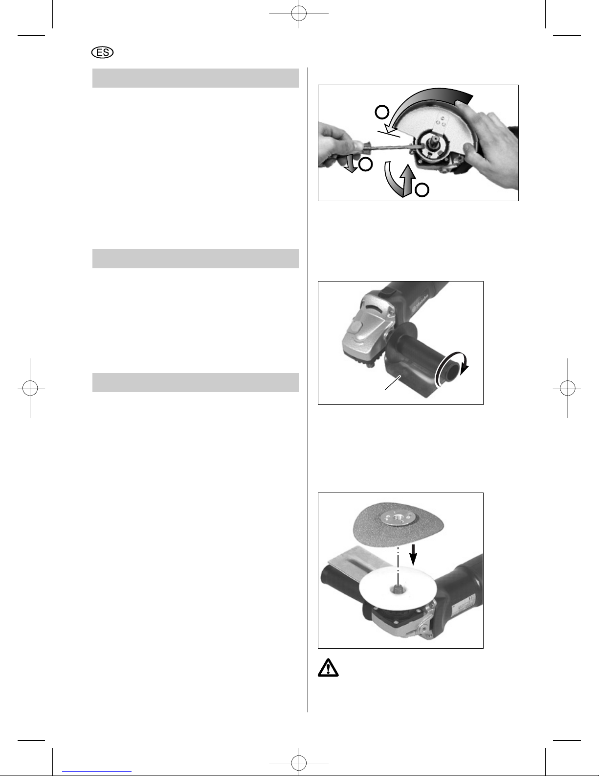
10 Mantenimiento
Antes de iniciar cualquier trabajo de
mantenimiento: ¡Desenchufe el cable de
alimentación de la caja de toma de red!
Limpieza del motor: limpiar con frecuencia a
fondo la herramienta a través de la rejilla de
ventilación inferior utilizando aire a presión. Para
ello, fijar bien la herramienta.
Sólo se deberá cambiar las escobillas de carbón
en los talleres del fabricante o en talleres
especializados. Encomiende todo trabajo de
control o de mantenimiento (requiriendo el
certificado correspondiente) al Servicio Postventa
de Metabo.
11 Eliminación de anomalías
Con sistema electrónico VTC, TC:
La indicación de señal electrónica (6) se
enciende, y el número de revoluciones bajo
carga se reduce.
La temperatura del bobinado es demasiado alta.
Dejar funcionar la amoladora angular en marcha
en vacío, hasta que la indicación de señal
electrónica se apague.
12 Accesorios
Utilizar exclusivamente accesorios originales de
Metabo.
Para adquirir accesorios, dirigirse al proveedor.
Para seleccionar los accesorios correctos se
debe indicar al proveedor el tipo exacto de la
herramienta eléctrica.
Página 4:
a Caperuza protectora del disco de tronzar con
carro guía para trabajar en piedra
b Protección para las manos
c Gafas de protección de visión panorámica
d Caperuza protectora de la muela de cazoleta
e Muela de cazoleta para alisar superficies
f Cepillos de alambre
g Platos de lijar láminas
h Discos de tronzar y desbaste
i Platos de apoyo elásticos
j Platos de apoyo con enganche velcro
k Discos de lijar
l Disco de tronzar de diamante
m Pieza de prolongación para trabajar con
platos de apoyo
n Llave para agujeros frontales (acodada)
o caperuza de protección de la muela de corte
12.1 Desmontar la caperuza protectora
12.2 Colocar la protección para las manos
(para trabajos con el plato de apoyo y
disco de lijar o cepillo)
Dado el caso, desmontar la herramienta, la
caperuza protectora y la empuñadura de
sujeción.
Enchufar la protección para las manos (b) sobre
la pieza roscada en la empuñadura (5). Alinear la
protección para las manos y montarla con la
empuñadura a la amoladora angular.
12.3 Colocar el plato de apoyo y la hoja
de lijar
¡Utilizar para este efecto únicamente la
tuerca de sujeción entregada con el
plato de apoyo!
b
1
2
3
34
ESPAÑOL
04_ES_Nafta_7970_0207 18.12.2007 14:52 Uhr Seite 34
Page 35

Colocar el plato de apoyo (i) en el husillo, como
se muestra en la figura. Atornillar el disco de lijar
(k) con la tuerca adjunta de sujeción del plato de
apoyo. Bloquear el husillo. Apretar manualmente
el disco de lijar con el plato de apoyo en el
sentido de las agujas del reloj.
Aflojar manualmente o bien, dado el caso,
mediante la llave para agujeros frontales (13).
12.4 Colocar el cepillo de alambre
Colocar la protección para las manos.
Desmontar la caperuza protectora (4). Bloquear
el husillo. Atornillar el cepillo de alambre (f) y
apretarlo con la llave de boca de entrecara
22 mm (7/8").
12.5 Colocar la muela de cazoleta con
caperuza de protección
Desmontar la caperuza protectora (4). Colocar la
caperuza protectora de la muela de cazoleta (d)
en la amoladora angular moviéndola hasta el
tope en la dirección indicada por la flecha.
Apretar el tornillo con un destornillador.
Colocar la brida de apoyo (10) en el husillo, con
cuidado de que no se pueda girar la brida de
apoyo en el husillo. Colocar la muela de cazoleta
sobre la brida de apoyo, asegurándose de que la
muela de cazoleta se apoye uniformemente
sobre la brida de apoyo.
Atornillar en el husillo la tuerca de sujeción (12) o
la tuerca de sujeción "Quick" (11). Bloquear el
husillo. Fijar la muela de cazoleta con la tuerca
de sujeción (12) o la tuerca de sujeción "Quick"
(11). Si se aplica la tuerca de sujeción (12),
utilizar la llave acodada para agujeros frontales (n).
Ajustar el saliente de la muela de cazoleta
respecto a la caperuza de protección según
necesidad (aproximadamente 0,5-1 cm). Para
este efecto, aflojar ambos tornillos de mariposa
y desplazar la caperuza de protección
uniformemente hacia arriba o hacia abajo.
Apretar nuevamente los tornillos de mariposa.
10
35
ESPAÑOL
04_ES_Nafta_7970_0207 18.12.2007 14:52 Uhr Seite 35
Page 36

12.6 Colocar la caperuza de protección de la
muela de corte
Retirar la caperuza de protección (4). Colocar la
caperuza de protección de la muela de corte (o)
alineando los tres puntos de retención del
dispositivo de protección con las ranuras de la
brida. Presionar la caperuza de protección, girarla
y colocarla entre el usuario y la muela. Fijar el
tornillo de sujeción para asegurar la caperuza de
protección.
13 Reparación
¡Los trabajos de reparación en
herramientas eléctricas deben ser
llevados a cabo exclusivamente por
electricistas especializados!
Las herramientas eléctricas de Metabo que
necesiten reparación pueden ser enviadas a la
dirección indicada en la penúltima página.
Sírvase incluir a la máquina enviada para su
reparación una descripción de la anomalía
determinada.
14 Protección ecológica
El material de embalaje utilizado por Metabo es
reciclable en un 100%. Las herramientas
eléctricas y sus accesorios fuera de uso
contienen grandes cantidades de materia prima y
plásticos que también pueden ser reciclados.
Debido a que el polvo de amolado puede
contener substancias tóxicas, no debe echarse a
la basura doméstica sino que debe eliminarse
correctamente en un puesto de recolección de
basura especial.
Este manual de instrucciones para el manejo está
impreso en papel blanqueado exento de cloro.
15 Especificaciones técnicas
Explicaciones sobre las especificaciones en la
página 2.
Reservados los derechos a modificaciones
relacionadas con el avance técnico.
D
max
= Diámetro máximo del disco abrasivo
n = N° de revol. de marcha en vacío
M = Rosca del husillo
P
1
= Potencia nominal absorbida
P
2
= Potencia suministrada
I
120V
= Intensidad de corriente a 120 V
a
hw
= Aceleración evaluada típicamente
en la zona mano/brazo
Niveles acústicos típicos en evaluación A:
L
pA
= Nivel de intensidad acústica
L
WA
= Nivel de potencia acústica
¡Llevar cascos de protección auditiva!
m = Peso
Valores de medición establecidos de acuerdo con
EN 50144.
Las especificaciones técnicas aquí indicadas se
entienden dentro de determinadas tolerancias
(conformes a las normas que rigen actualmente).
o
36
ESPAÑOL
04_ES_Nafta_7970_0207 18.12.2007 14:52 Uhr Seite 36
Page 37

Índice
1 Utilização correcta
2 Regulamentos gerais de segurança
3 Indicações especiais de segurança
4 Generalidades
5 Características especiais do produto
6 Colocação em funcionamento
7 Ligar e desligar
8 Ajustar as rotações
(dependente do equipamento)
9 Colocação das ferramentas
9.1 Colocar discos de corte e discos
rebarbadores
9.2 Fixar e soltar a porca de sujeição
"Quick" (11): apenas para utilização do
disco de rebarbar do tipo 27
9.3 Fixar e soltar a porca de sujeição (12):
para discos de corte do tipo 1
OU discos de rebarbar do tipo 27
10 Manutenção
11 Eliminação de perturbações
12 Acessórios
12.1 Retirar o protector
12.2 Colocar protecção das mãos
12.3 Colocar o prato de apoio e a folha
de lixar
12.4 Colocar a escova de arame
12.5 Colocar o rebolo em forma de taça
com protector
12.6 Ajustar o resguardo do disco de
corte
13 Reparação
14 Protecção do meio ambiente
15 Dados técnicos
1 Utilização correcta
As rebarbadoras angulares, com acessórios
originais Metabo, são indicadas para corte,
rebarba com discos de apoio e escovagem de
metal, betão, pedra e materiais semelhantes sem
utilização de água.
Em nenhum caso devem ser utilizadas folhas de
serra, correntes de serrar ou semelhantes.
O utilizador será o único responsável pelos danos
decorrentes de uma utilização incorrecta. As
normas gerais de prevenção de acidentes e as
indicações de segurança em anexo devem ser
respeitadas.
2 Regulamentos gerais de
segurança
1 ADVERTÊNCIA! Ler e entender todas
instruções.
A não-observação destas instruções listadas
abaixo pode causar choque eléctrico, incêndio
e/ou ferimentos graves.
GUARDAR ESTAS INSTRUÇÕES COM
CUIDADO.
2 Área de trabalho
2.1 Manter a área de trabalho limpa e bem
iluminada. Bancadas obstruídas e áreas mal-
iluminadas propiciam acidentes.
2.2 Não operar ferramentas eléctricas em
atmosferas com risco de explosão, bem como
na presença de líquidos inflamáveis, gases ou
pó. Ferramentas eléctricas gerar faíscas que
podem causar a ignição no pó ou fumo.
2.3 Manter espectadores, crianças e
visitantes à distância ao trabalhar com
ferramentas eléctricas. Distracções podem
causar a perda do controle da máquina.
3 Segurança eléctrica
3.1 Ferramentas com aterramento devem ter
sua ficha conectada a uma tomada eléctrica
apropriadamente instalada e ligada ao terra de
acordo com todos os regulamentos e
prescrições válidos. Nunca remover o terminal
de aterramento ou modificar a ficha de
maneira alguma. Nunca utilizar fichas com
adaptadores. Mandar um electricista
especializado controlar a tomada no caso de
surgirem dúvidas sobre se a mesma está com
o fio terra correctamente ligado. Se a
ferramenta apresentar defeito na parte eléctrica
ou parada, providenciar uma via de baixa
resistência para conduzir a electricidade para
longe do operador.
Instruções de serviço
Estimado cliente,
muito obrigado pela confiança demonstrada ao comprar a nova ferramenta eléctrica da Metabo. Cada
ferramenta eléctrica da Metabo é cuidadosamente testada e submetida aos rigorosos controlos de
qualidade especificados na garantia de qualidade da Metabo. No entanto, a duração da ferramenta
eléctrica depende muito de si. Por favor, tenha em atenção as informações constantes nestas
instruções de serviço e nos documentos em anexo. Quanto mais cuidadosamente tratar a ferramenta
eléctrica da Metabo, mais tempo ela irá realizar o seu serviço com fiabilidade.
PORTUGUÊS
37
05_PT_Nafta_7970_0207 18.12.2007 14:52 Uhr Seite 37
Page 38

Referente apenas a ferramentas da Classe I
(com aterramento).
3.2 Ferramentas com duplo isolamento são
equipadas com uma ficha polarizada (um dos
pinos da ficha é mais largo do que o outro).
Esta ficha só pode ser conectada em uma
tomada polarizada em uma única direcção.
Caso a ficha não conectar de forma
apropriada na tomada, inverter a ficha na
tomada. Caso a mesma ainda não encaixar
correctamente na tomada, entrar em contacto
com um electricista especializado para que o
mesmo instale uma tomada polarizada. Nunca
modificar a ficha. O duplo isolamento elimina
a necessidade de cabo com aterramento trifásico
e fonte de alimentação aterrada.
Aplicável apenas a ferramentas da Classe II
(duplo isolamento).
3.3 Evitar contacto com o corpo em
superfícies aterradas tais como tubulações,
radiadores e frigoríficos. O risco de choque
eléctrico aumentará se o corpo do operador está
ligado ao terra.
3.4 Não expor ferramentas eléctricas a chuva
ou intempéries. A entrada de água na
ferramenta eléctrica aumenta o risco de choque
eléctrico.
3.5 Não maltratar o cabo eléctrico. Nunca
utilizar o cabo eléctrico para carregar a
ferramenta ou para puxar a ficha da tomada.
Manter o cabo eléctrico afastado de calor,
óleo, cantos afiados ou partes móveis.
Substituir imediatamente cabos danificados.
Cabos danificados aumentam o risco de choque
eléctrico.
3.6 Ao operar ferramentas eléctricas no
exterior, utilizar um cabo eléctrico para
exteriores, denominado “W-A” ou “W”. Estes
cabos são apropriados para utilização no exterior
e reduzem o risco de choque eléctrico.
4 Segurança Pessoal
4.1 Permanecer atento, prestar atenção no
que se está a fazer e utilizar bom senso
quando operar uma ferramenta eléctrica. Não
utilizar a ferramenta quando estiver cansado
ou sob influência de drogas, álcool ou
medicamentos. Um momento de falta de
atenção ao se operar ferramentas eléctricas pode
causar ferimentos pessoais graves.
4.2 Utilizar trajes apropriados. Nunca usar
roupas soltas ou portar acessórios. Prender
cabelos compridos. Manter seu cabelo, trajes
e luvas afastados de partes móveis. Roupas
soltas, acessórios pessoais ou cabelos longos
podem ser apanhados pelas peças em
movimento.
4.3 Evitar acidentes ao arrancar. Assegurar-se
de desligar a máquina antes de encaixar a
ficha na tomada. Carregar a ferramenta com o
dedo no interruptor ou ligar ferramentas com o
interruptor ligado aumenta o risco de acidentes.
4.4 Remover chaves de ajuste ou extractores
antes de ligar a ferramenta. Um extractor ou
chave que continue conectada a parte rotativa da
ferramenta pode resultar em ferimento pessoal
grave.
4.5 Não se inclinar em excesso. Manter uma
posição dos pés e equilíbrio apropriados todo
tempo. Posição dos pés e equilíbrio apropriados
permitem um melhor controle da ferramenta no
caso de situações inesperadas.
4.6 Utilizar equipamento de segurança.
Sempre utilizar protecção para os olhos.
Máscara respiratória anti-pó, sapatos de
segurança anti-escorregão, capacete protector e
protector auditivo devem ser usados para
condições apropriadas.
5. Utilização e cuidados para com a
ferramenta
5.1 Utilizar fixadores ou outro meio
apropriado para segurar e prender a peça em
trabalho em uma plataforma fixa. Segurar a
peça em trabalho com as mãos ou contra o corpo
causa instabilidade e pode levar a perda de
controle.
5.2 Não forçar a ferramenta. Usar a
ferramenta correcta para o seu uso
apropriado. A ferramenta correcta irá executar o
trabalho de forma apropriada e de forma mais
segura conforme a mesma foi concebida.
5.3 Não utilizar a ferramenta caso o
interruptor não desligue/ligue a mesma.
Qualquer ferramenta que não possa ser
comandada pelo seu interruptor apresenta risco
e deve ser reparada.
5.4 Desconectar a ficha da fonte de
alimentação antes de efectuar qualquer
ajuste, trocar acessórios ou guardar a
ferramenta. Tomar medidas preventivas de
segurança reduz o risco de arrancar a ferramenta
acidentalmente.
5.5 Armazenar as ferramentas fora do alcance
de crianças ou outras pessoas não-treinadas.
Ferramentas são perigosas nas mãos de
pessoas não-treinadas.
5.6 Efectuar a manutenção das ferramentas
com cuidado. Manter as ferramentas de corte
limpas e amoladas. Ferramentas com lâminas
afiadas que sofrem manutenção apropriada são
mais fáceis de montar e de controlar.
5.7 Controlar em relação a mau-alinhamento
ou peças móveis presas, quebra de peças ou
qualquer outra condição que possa afectar a
operação da ferramenta. Caso a mesma esteja
danificada, mandar reparar a ferramenta antes
de sua utilização. Muitos acidentes são
causados por ferramentas com manutenção
deficiente.
38
PORTUGUÊS
05_PT_Nafta_7970_0207 18.12.2007 14:52 Uhr Seite 38
Page 39

5.8 Utilizar apenas acessórios recomendados
pelo fabricante para seu modelo. Acessórios
apropriados para uma ferramenta podem se
tornar perigosos quando utilizados com outra
ferramenta.
6 ASSISTÊNCIA PÓS-VENDAS
6.1 A assistência pós-vendas da ferramenta
deverá ser efectuada apenas por pessoal
qualificado. Assistência pós-vendas ou
manutenção efectuadas por pessoal nãoqualificado pode resultar em risco de ferimentos.
6.2 Ao efectuar a manutenção de uma
ferramenta, devem ser utilizadas
exclusivamente peças sobressalentes
idênticas. Seguir as instruções de
manutenção na secção correspondente deste
manual. O uso de peças não-autorizadas ou não-
observação das instruções de manutenção pode
criar o risco de choque eléctrico ou ferimento.
3 Indicações especiais
de segurança
Antes de utilizar a ferramenta eléctrica, leia
atenta e integralmente as indicações de
segurança (caderno vermelho) em anexo e as
instruções de serviço. Guarde todos os
documentos que acompanham a ferramenta
eléctrica. Se a entregar a outra pessoa,
disponibilize também a documentação.
Para a sua segurança e para a
segurança da sua ferramenta
eléctrica, tenha atenção às
partes de texto identificadas com
este símbolo!
Use sempre óculos de protecção e protecção
auditiva. Use também outros equipamentos de
protecção individual, como por exemplo, luvas,
vestuário de trabalho e capacete.
Antes da utilização da rebarbadora angular,
deverá colocar o punho (5) e conduzir a máquina
sempre com ambas as mãos.
Pó condutivo pode depositarse no interior da máquina,
particularmente durante a
maquinação de metais. O
que pode causar a passagem de energia
eléctrica para a carcaça da máquina. Isto poderá
fundamentar o perigo temporário de um choque
eléctrico. Por isso é necessário limpar regular e
frequentemente a máquina soprando ar
comprimido através das ranhuras de ventilação
traseiras, com ela a trabalhar. Deve segurar-se
bem a máquina.
Recomenda-se a aplicação de um sistema de
aspiração estacionário e a intercalação de um
disjuntor de corrente de avaria (FI).
A formação de pó durante o trabalho é muitas
vezes prejudicial à saúde (p. ex. ao trabalhar
madeira de carvalho e de faia ou ao decapar tinta
que possa conter chumbo ou outras substâncias
nocivas). Este pó não deve ser absorvido pelo
organismo. Utilize um dispositivo de aspiração de
pó e, adicionalmente, utilize uma máscara de
protecção contra o pó adequada! Retire
cuidadosamente o pó acumulado através, p.ex.
da aspiração, utilizando para isso um aspirador
de pó adequado!
O pó pode ser explosivo.
Materiais que, ao serem processados, produzam
poeiras e vapores nocivos para a saúde (p. ex.,
amianto) não podem ser trabalhados
Certifique-se de que as faíscas produzidas
durante a utilização não originam nenhum perigo,
p. ex. atingir o utilizador ou outras pessoas ou
incendiar substâncias inflamáveis. As áreas
expostas ao perigo de incêndio devem ser
protegidas com coberturas ignífugas. Tenha
sempre um extintor pronto a ser utilizado nas
áreas expostas ao perigo de incêndio.
Utilize sempre acessórios que obedeçam às
seguintes exigências mínimas.
Tomar atenção ao diâmetro
máximo do disco de esmerilar
(consultar Dados Técnicos).
Utilizar, no mínimo,
"máx 80 m/s".
O diâmetro da furação do
disco de rectificar (3) deve
ajustar-se sem folga à flange
de apoio (10). Não utilizar
quaisquer adaptadores ou
peças redutoras.
O número de rotações nmax
permitido deve corresponder,
no mínimo, ao número de
rotações em vazio da
ferramenta eléctrica (consultar
Dados Técnicos).
Utilizar, no mínimo,
"máx 45 m/s".
Após cada substituição de ferramenta, deverá
efectuar um funcionamento experimental. Para o
efeito, deve segurar bem a máquina com ambas
as mãos.
max. 80 mm
3
10
39
PORTUGUÊS
05_PT_Nafta_7970_0207 18.12.2007 14:52 Uhr Seite 39
Page 40

Afastar a rebarbadora angular do próprio corpo.
Verificar que ninguém se encontra na área de
perigo. Deixar funcionar a rebarbadora angular
durante cerca de 30 segundos.
A rebarbadora funcionará ainda durante cerca de
5 segundos por inércia após ter sido desligada.
Observar as indicações do fabricante da
ferramenta ou do acessório!
Proteger o disco de gorduras e pancadas!
Ferramentas danificadas, descentradas e
vibrantes não podem ser utilizadas.
Nunca utilizar discos de corte para rebarbar! Os
discos de corte nunca devem ser expostos a
qualquer pressão lateral. Ao utilizar discos de
corte e de rebarbar, trabalhar sempre com o
protector (14) colocado!.
Utilizar apenas ferramentas a seco!
Não agarrar na ferramenta em funcionamento.
Perigo de lesões!
Evitar danos em condutas de gás e de água,
condutores eléctricos e paredes suportantes
(estática).
Ao utilizar a ferramenta eléctrica ao ar livre,
intercalar um disjuntor FI com corrente de
activação máxima (30 mA)!
Ligamento permanente da rebarbadora: A fim de
evitar um arranque involuntário: desbloquear
sempre o interruptor quando a ficha for puxada
da tomada ou caso haja uma interrupção de
corrente.
Utilizar peças distanciadoras flexíveis, quando
estas foram colocadas à disposição juntamente
com o produto abrasivo e quando são exigidas.
Ao empregar discos com orifícios roscados,
observar se a rosca no disco é suficientemente
longa para absorver o comprimento do veio.
Fixar seguramente a peça.
Certifique-se de que as aberturas de ventilação
estão livres durante os trabalhos sob condições
de pó. Caso seja necessário remover o pó,
desconecte primeiramente a ferramenta eléctrica
da rede de alimentação de corrente (use objetos
não metálicos) e evite danificar as peças
internas.
Os discos de rebarba devem ser manejados e
guardados cuidadosamente e de acordo com as
instruções do fabricante.
Se não for possível evitar a utilização da
ferramenta eléctrica em locais húmidos, deve ser
utilizado um Circuito para Protecção Contra Falta
de Terra para fornecer a alimentação à sua
ferramenta. Luvas de borracha e calçado de
electricista aumentarão ainda mais a sua
segurança pessoal.
Sempre que utilizar discos de lixar, o resguardo
deve estar fixo à ferramenta e posicionado para
máxima segurança, de forma a que só uma
fracção mínima do disco está exposta do lado
que se utiliza a ferramenta.
Discos de lixar ou qualquer outro acessório
devem ter uma velocidade máxima de utilização
segura superior às "rotações em vazio" indicadas
na placa de características da ferramenta.
Utilize sempre a pega auxiliar para um
controlo máximo sobre a reacção de binário
ou ricochete. A utilização da lixadeira sem a
pega lateral poderá causar a perda de controlo
da mesma, resultando em eventuais lesões
pessoais graves.
Antes de utilizar uma lixadeira ou colocar um
novo disco, examine o disco de lixar quanto a
lascas e fissuras. Retire imediatamente discos
danificados. Deixe funcionar a ferramenta sem
carga durante um minuto, segurando-a num
direcção afastada das pessoas. Discos com
defeitos quebrarão normalmente durante este
intervalo de tempo.
Manuseie com cuidado tanto a ferramenta
como discos de lixar individuais para evitar
que lasquem ou fissurem. Coloque um disco
novo se deixar cair a ferramenta durante o
trabalho. Não utilize um disco que possa estar
danificado. Fragmentos de um disco que se
desintegre durante o funcionamento serão
projectados a alta velocidade, batendo
possivelmente em si ou em espectadores.
Advertência! Algum pó produzido durante a
lixagem, serragem, rebarbagem, perfuração, e
outras actividades de construção com
ferramentas contém produtos químicos que se
sabe poderem causar o cancro, malformações
congénitas ou outros danos no sistema
reprodutivo. Alguns exemplos destes produtos
químicos:
– chumbo de tintas à base de chumbo,
– sílica cristalina de tijolos e cimento e outros
produtos de alvenaria, e
– arsénico e crómio de madeira tratada
quimicamente.
O risco pessoal destas exposições varia em
função da frequência com a qual executa este
tipo de trabalho. Para reduzir a sua exposição a
estes produtos químicos, trabalhe em áreas bem
ventiladas e com equipamento de segurança
aprovado, tais como máscaras de protecção
contra pó especificamente concebidas para
filtrarem partículas microscópicas.
Ler as instruções de operação
Usar óculos de protecção
40
PORTUGUÊS
05_PT_Nafta_7970_0207 18.12.2007 14:52 Uhr Seite 40
Page 41

Caso a embraiagem automática actue, desligue
imediatamente a rebarbadora angular e elimine a
causa.
Não utilize esta ferramenta com lâminas “para
talhar madeira”. A utilização de lâminas “para talhar madeira” pode originar contra-golpes, podendo perder-se o controlo sobre a ferramenta e
ferir-se gravemente.
O punho danificado ou rachado deve ser
substituído. Não operar a máquina com o punho
defeituoso.
Símbolos na Ferramenta:
Construção da Classe II
V volts
A amperes
Hz hertz
.../min rotações por minuto
~ corrente alternada
n0 velocidade sem carga
As indicações „C“ e „US“ do lado da
marca CSA significam que o produto
foi avaliado e aprovado conforme os
padrões CSA e ANSI/UL, para a
respectiva utilização no Canadá
e nos EUA.
4 Generalidades
Ver página 3 (por favor, desdobre).
1* Interruptor de corrediça (de engatar)
2 Botão de bloqueis do fuso
3 * Disco de rectificar
4 Protector
5 * Punho / Punho com amortecedor de
vibrações
6 * Indicador do sinal electrónico
(só VTC, TC)
7 * Roda de ajuste para o ajuste das
rotações (VC, VTC)
8 Bloqueio do interruptor
9 Gatilho do interruptor
10 * Flange de apoio
11 * Porca de fixação "Quick"
ou, como alternativa,
12 * Porca de fixação com
13 * Chave de dois pinos
14 * Flange interior (para discos do tipo 27
com 6" de diâmetro)
*dependente do equipamento
5 Características especiais
do produto
Embraiagem de segurança Metabo
S-automatic
Se a ferramenta utilizada
emperra ou prende, o fluxo de
força ao motor é limitado. Por
causa da alta força que surge
nisto, segure a máquina
sempre com ambas as mãos
nos punhos laterais previstos,
ocupe uma posição segura e
trabalhe com atenção dobrada.
Motor Marathon
O motor Marathon protegido
contra o pó, da Metabo,
providencia uma duração até
50% mais longa através da
grelha de protecção do
enrolamento e da bobina
excitadora revestida com
pintura a pó, da Metabo.
Protector
O ajuste do protector sem a necessidade de
utilizar ferramentas possibilita a adequação em
segundos a diferentes utilizações.
Escovas de carvão Autostop
No caso de escovas de carvão gastas, a
ferramenta eléctrica desliga automaticamente,
evitando danificações do induzido.
Punho adicional com amortecedor de
vibrações (dependendo do equipamento):
para trabalho confortável no funcionamento
contínuo.
Electrónica VC/VTC/TC
(dependente do equipamento)
A electrónica possibilita o esmerilamento de
acordo com o material (VC/VTC) e uma rotação
quase constante, mesmo em carga (VC/VTC/TC).
A electrónica Vario-Tacho-Constamatic VTC /
Tacho-Constamatic TC dispõe ainda de um
delimitador de corrente de arranque, de um
arranque electrónico suave, controlo da
temperatura da bobina, assim como de protecção
de rearranque electrónica.
Poderá obter informações sobre o equipamento
da sua ferramenta eléctrica nos Dados Técnicos.
41
PORTUGUÊS
05_PT_Nafta_7970_0207 18.12.2007 14:52 Uhr Seite 41
Page 42
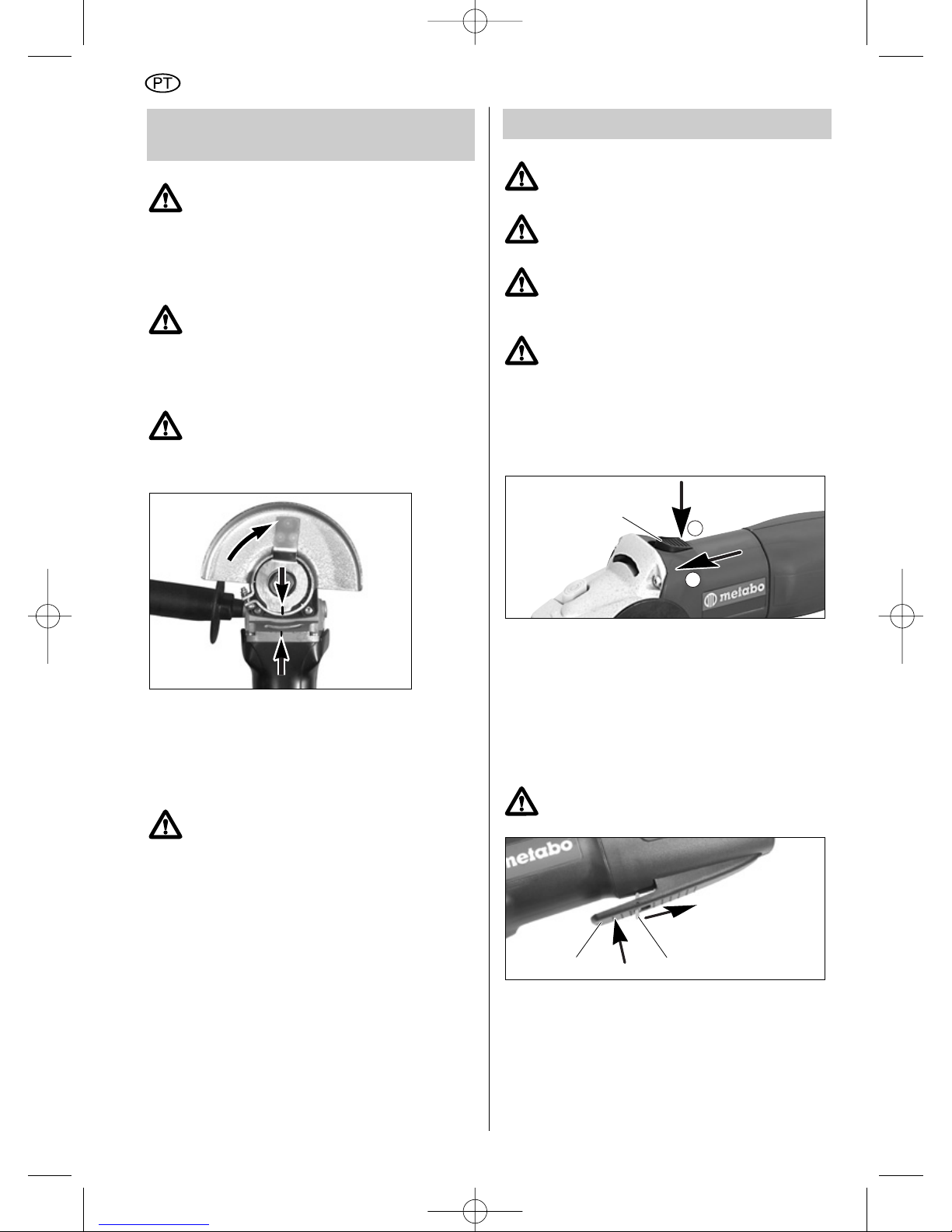
6 Colocação em
funcionamento
Antes da colocação em funcionamento,
compare a tensão e a frequência de
rede indicadas na placa de
características com os dados da sua
rede de alimentação. Veja se estas
coincidem.
Colocar o punho
Antes do início do trabalho, e por
questões de segurança, deverá colocar
sempre o punho (5) no lado direito ou
esquerdo da rebarbadora angular.
Colocar o protector
(para trabalhos com discos de rectificar)
Utilize o protector correcto para o tipo
de disco a ser utilizado. Consultar as
secções 12.4 e 12.5 para o protector do
rebolo em forma de taça e do disco de
corte.
Retirar a porca de fixação (12) ou a porca de
fixação "Quick" (11) e a flange de apoio (10) do
fuso. Ao colocar o protector (4) na rebarbadora
angular, ter em atenção que a ranhura no
protector deve coincidir com a marcação na
rebarbadora angular.
Rodar o protector de modo a que a área
fechada aponte para o utilizador!
Ligar a ficha à tomada de corrente.
No caso de electrónica VTC, TC (dependente do
equipamento):
O indicador de sinal electrónico vermelho (6)
acende por breves instantes ao ligar a ficha à
tomada de corrente, indicando que a ferramenta
está pronta a funcionar.
7 Ligar e desligar
Conduzir a máquina sempre com as
duas mãos!
Ligar primeiro. Depois aproximar a
ferramenta à peça a trabalhar!
Deve evitar-se que a máquina aspire
poeira e limalhas. Ao ligar e desligar a
máquina, afastá-la da poeira que se
tenha depositado.
Pousar a máquina depois de desligada
apenas quando o motor tiver parado.
Com electrónica VTC, TC: o mostrador vermelho
de sinal electrónico (6) acende brevemente ao
ligar.
Máquinas com trinco de ligação (1):
(máquinas com a designação W... ou WE...)
Ligar: empurrar o trinco de ligação (1) para a
frente até que engate.
Desligar: pressionar no extremo traseiro do
trinco de ligação.
Máquina com bloqueio de ligação
(Interruptor de segurança devido à
impossibilidade de retenção):
(máquinas com a designação WEP…)
Jamais carregar ou pendurar a máquina
pelo interruptor integrado no punho (9).
Ligar: empurrar o bloqueio do interruptor (8) na
direcção da seta e carregar no gatilho do
interruptor (9).
Desligar: soltar o gatilho do interruptor (9).
Máquinas com gatilho do interruptor (9):
(máquinas com a designação WP... ou WPS...)
9 8
1
0
I
42
PORTUGUÊS
05_PT_Nafta_7970_0207 18.12.2007 14:52 Uhr Seite 42
Page 43

Ligar: empurrar o bloqueio do interruptor (8) na
direcção da seta e carregar no gatilho do
interruptor (9).
Desligar: soltar o gatilho do interruptor (9).
Ligação contínua:
(máquinas com a designação WP...)
Ligar a rebarbadora angular e empurrar o
bloqueio do interruptor (8) para a frente até que
engate.
Desligar a ligação contínua:
Pressionar brevemente o gatilho do interruptor (9)
e soltar.
Protecção de rearranque
(apenas com electrónica VTC/TC):
Caso seja introduzida a ficha de tomada de
corrente ou seja religada a corrente com o
interruptor de corrediça ligado, a rebarbadora
angular não arrancará. O indicador de sinal
electrónico vermelho (6) pisca. Desligue a
rebarbadora angular e volte a ligá-la.
8 Ajustar as rotações
(dependente do equipamento)
Ajustar as rotações recomendadas com a roda de
ajuste (7).
Disco de corte, disco rebarbador, rebolo em
forma de taça, disco de corte de diamante:
rotação elevada
Escova: Rotação média
Prato de lixar: Rotação baixa até média
Ao trabalhar com rotação baixa, encostar a
ferramenta eléctrica apenas levemente.
9 Colocação
das ferramentas
Antes de qualquer trabalho de
substituição, deverá retirar a ficha da
tomada de corrente e assegurar-se de
que a rebarbadora angular se encontra
desligada.
Bloquear o fuso
Premir o botão de bloqueio do fuso (2) e rodar o
fuso à mão até que o botão de bloqueio do fuso
engate audivelmente.
9.1 Colocar discos de corte e discos
rebarbadores
Localize a flange interior (10) para discos de
corte do tipo 1, (10) para discos do tipo 27 com 5"
de diâmetro ou menores, ou (14) para discos do
tipo 27 com 6" de diâmetro, de acordo com a
imagem, assegurando-se de que a flange interior
não pode rodar no fuso.
Colocar o disco de corte ou o disco rebarbador
na flange de apoio, de acordo com a figura. Ter
atenção para que o disco apoie uniformemente
na flange de apoio. Ao utilizar o disco de corte, a
flange de chapa deverá estar colocada sobre a
flange de apoio.
9.2 Fixar e soltar a porca de sujeição
"Quick" (11): apenas para utilização do
disco de rebarbar do tipo 27
Fixar
11
10
10
14
43
PORTUGUÊS
05_PT_Nafta_7970_0207 18.12.2007 14:52 Uhr Seite 43
Page 44

Em ferramentas com uma espessura
superior a 8 mm na zona de aperto, em
vez da porca de sujeição Quick (11),
utilize a porca de sujeição (12) com
chave de pinos (13).
Colocar a porca de fixação "Quick" (11) nas
ranhuras do fuso, de acordo com a figura.
Bloquear o fuso. Apertar a porca de fixação
"Quick" (11) à mão, no sentido dos ponteiros do
relógio. Aperte a porca de sujeição Quick
rodando vigorosamente o disco de corte no
sentido dos ponteiros do relógio.
Soltar
Após desligar a rebarbadora angular, ela funciona
por inércia durante cerca de 5 segundos. Pouco
antes de a ferramenta de rebarbar parar, premir o
botão de bloqueio do fuso (2) – a porca de
fixação "Quick" solta-se.
A paragem do fuso com o botão de
bloqueio do fuso (2) só é permitida com
a utilização da porca de fixação
"Quick"!
Desaparafusar a porca de fixação "Quick".
9.3 Fixar e soltar a porca de sujeição (12):
para discos de corte do tipo 1
OU discos de rebarbar do tipo 27
Fixar
Para discos mais finos do que 3/16", rode a porca
de sujeição (12) sobre o fuso com o colar para
cima, de forma a que o disco possa ser bem
esticado. Aperte bem utilizando a chave de dois
pinos (13).
Para discos de 3/16" ou mais espessos, rode a
porca de sujeição (12) sobre o fuso com o colar
para baixo, de forma a que o colar cubra o ID do
disco. Aperte bem utilizando a chave de dois
pinos (13).
Bloquear o fuso. Colocar a chave de dois pinos
(13) na porca de fixação (12) e apertar no sentido
dos ponteiros do relógio.
Soltar
Bloquear o fuso, soltar a porca de fixação com
a chave de dois pinos (13) e desaparafusar.
10 Manutenção
Deverá retirar a ficha da tomada de corrente
antes de executar quaisquer trabalhos de
manutenção!
Limpeza do motor: limpar regular e
frequentemente a máquina soprando ar
comprimido através das ranhuras de ventilação
traseiras. Deve segurar-se bem a máquina.
As escovas de carvão só deverão ser
substituídas pelo fabricante ou numa oficina
autorizada para o efeito. Verificações e
manutenções (com a respectiva documentação)
deverão ser executadas por um serviço de
assistência pós-venda da Metabo.
11 Eliminação de perturbações
Com electrónica VTC, TC:
O indicador de sinal electrónico (6) acende e a
rotação em carga diminui.
A temperatura da bobina é demasiado elevada.
Deixar a rebarbadora angular funcionar em vazio
até que o indicador de sinal electrónico se
apague.
12 Acessórios
Utilize apenas acessórios originais da Metabo.
Se necessitar de acessórios, dirija-se, por favor,
ao seu vendedor.
Para a escolha do acessório correcto, informe o
seu vendedor sobre o modelo exacto da sua
ferramenta eléctricar.
12
13
12
12
12
14
44
PORTUGUÊS
05_PT_Nafta_7970_0207 18.12.2007 14:52 Uhr Seite 44
Page 45
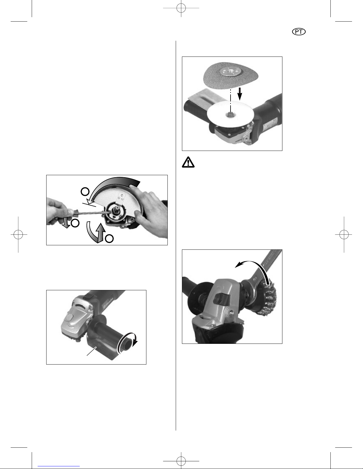
Consultar a página 4:
a Protector do disco de corte com cursor de
guia para trabalhar pedra
b Protecção das mãos
c Óculos de protecção de visão integral
d Protector do rebolo em forma de taça
e Rebolo em forma de taça para alisar
superfícies
f Escovas de arame
g Prato lamelar de lixagem
h Discos de corte e discos rebarbadores
i Prato de apoio elástico
j Prato de apoio com velcro aderente
k Folhas circulares de lixar
l Disco de corte de diamante
m Peça de prolongamento para trabalhos com
pratos de apoio
n Chave de dois pinos (acotovelada)
o resguardo do disco de corte
12.1 Retirar o protector
12.2 Colocar protecção das mãos
(para trabalhos com prato de apoio e
folha de lixar ou escova)
Eventualmente, retirar a ferramenta, o protector e
a pega.
Colocar a protecção para mãos (b) sobre a peça
roscada no punho (5). Ajustar a protecção para
mãos e colocá-la com o punho na rebarbadora.
12.3 Colocar o prato de apoio e a folha de
lixar
Utilizar apenas a porca de fixação
fornecida com o prato de apoio!
Colocar o prato de apoio (i) no fuso, de acordo
com a figura. Aparafusar a folha de lixar (k) com a
porca de fixação do prato de apoio fornecida.
Bloquear o fuso. Apertar à mão a folha de lixar
com o prato de apoio, no sentido dos ponteiros
do relógio.
Soltar à mão ou, eventualmente, com a chave de
dois pinos (13).
12.4 Colocar a escova de arame
Colocar a protecção para mãos.
Retirar o protector (4). Bloquear o fuso.
Aparafusar a escova de arame (f) e apertar com
chave de bocas de 22 mm (7/8").
b
1
2
3
45
PORTUGUÊS
05_PT_Nafta_7970_0207 18.12.2007 14:52 Uhr Seite 45
Page 46

12.5 Colocar o rebolo em forma de taça
com protector
Retirar o protector (4). Colocar na rebarbadora
angular o protector do rebolo em forma de taça
(d) na direcção da seta, até ao batente. Apertar
os parafusos com chave de fendas.
Colocar a flange de apoio (10) no fuso. Observar
para que a flange de apoio não rode no fuso.
Colocar o rebolo em forma de taça na flange de
apoio.
Apertar a porca de fixação (12) ou a porca de
fixação "Quick" (11) no fuso. Bloquear o fuso.
Fixar o rebolo em forma de taça com a porca de
fixação (12) ou com a porca de fixação "Quick"
(11).
Ao utilizar a porca de fixação (12), utilizar chave
acotovelada de dois pinos (n).
Se necessário, ajuste a saliência do rebolo em
forma de taça em relação à distância à cobertura
de protecção (cerca de 0,5 - 1 cm). Para o efeito,
solte os dois parafusos de orelhas e ajuste
uniformemente a cobertura de protecção para
cima ou para baixo. Aperte novamente os
parafusos de orelhas.
12.6 Ajustar o resguardo do disco de corte
Retire o resguardo do disco (4). Ajuste o
resguardo do disco de corte (o), alinhando as 3
nervuras de retenção salientes no resguardo com
as ranhuras na flange. Pressione o resguardo
completamente sobre a flange, depois rode-o e
posicione-o entre o utilizador e o disco. Aperte
o parafuse de sujeição para fixar o resguardo na
sua posição.
13 Reparação
As reparações das ferramentas
eléctricas só devem ser efectuadas por
electricistas especializados!
As ferramentas eléctricas da Metabo que
necessitem de reparação podem ser enviadas
para os endereços indicados na penúltima
página. No envio para reparação descreva, por
favor, o defeito verificado.
14 Protecção do meio
ambiente
As embalagens da Metabo são 100% recicláveis.
As ferramentas eléctricas e os acessórios usados
contêm uma grande quantidade de matéria prima
e material sintético útil, que também podem ser
submetidos a um processo de reciclagem. Dado
que o pó resultante da lixagem pode conter
produtos nocivos, não o deve remover
juntamente com o lixo doméstico, mas sim
entregá-lo numa estação de recolha de lixo
especial apropriada.
Estas instruções de serviço estão impressas em
papel branqueado sem cloro.
o
10
46
PORTUGUÊS
05_PT_Nafta_7970_0207 18.12.2007 14:52 Uhr Seite 46
Page 47

15 Dados técnicos
Esclarecimentos em relação às informações da
página 2.
Reservado o direito a proceder a modificações no
sentido do desenvolvimento técnico.
D
max
= Diâmetro máximo do disco
de rebarbar/rectificar
n = Rotação em vazio
M = Rosca do fuso
P
1
= Consumo nominal
P
2
= Potência debitada
I
120V
= Corrente a 120 V
a
hw
= Aceleração típica avaliada na zona
da mão e do braço
Nível acústico A típico calculado:
L
pA
= Nível da pressão acústica
L
WA
= Nível de potência acústica
Utilizar protecção acústica!
m = Peso
Valores medidos de acordo com a norma
EN 50144. Os dados técnicos indicados são
tolerantes (de acordo com os padrões válidos
individuais).
47
PORTUGUÊS
05_PT_Nafta_7970_0207 18.12.2007 14:52 Uhr Seite 47
Page 48

Metabowerke GmbH,
72622 Nürtingen, Germany
www.metabo.com
01_Ums_Nafta_7970_0207 18.12.2007 14:48 Uhr Seite 48
 Loading...