

Merrychef MicroaireRMC1003 Service Manual

Page 1 Microaire Ovens 32Z3311e Issue 5
CAUTION MICROWAVE EMISSIONS
DO NOT BECOME EXPOSED TO EMISSIONS FROM THE MICROWAVE
GENERATOR OR PARTS CONDUCTING MICROWAVE ENERGY
SERVICE MANUAL
Microaire
SERVICE MANUAL
For all Microaire models manufactured from January 2001
Part No. 32Z3311e Issue No. 6

Page 2 Microaire Ovens 32Z3311e Issue 5
Table of Contents
Safety Code ........................................................................... 3
Product Specifications ........................................................... 4
Principles of Operation .......................................................... 5
Installation Instructions .......................................................... 6
Error Codes and Diagnostics ................................................ 7
Main Features ........................................................................ 8
Electronic Controls ................................................................9
Manual Controls ..................................................................10
A – Power Output Testing to EN 60335-2-90:1996 ............. 11
B - Power Output Testing ....................................................12
C - Power Transformer Test ................................................ 12
D - High Voltage Capacitor Test .......................................... 13
E - High Voltage Rectifier Test ............................................ 13
Diagram - Casework ............................................................ 14
Diagram - Door Mechanism ................................................15
Oven Cavity Components & Hot Air System .......................16
Oven Door Assembly ........................................................... 17
Magnetron & Door Interlock Components ...........................18
F - Interlock Operation ......................................................... 19
Error Light Operation .......................................................... 19
Major Electrical Components .............................................. 20
Input Filters and Fuses ...................................................20-21
Input Wiring Details ........................................................22-23
HT Components ..................................................................24
Electronic Control Panel Assembly .....................................25
Manual Controls Panel Assembly ........................................ 26
Membrane Panel Circuit ...................................................... 27
Complete Spare Part Listing ..........................................28-29
Electrical Diagram - RMC1003xxEE5 / XE5 ........................30
Electrical Diagram - RMC1003RS RF / HST ....................... 31
Merrychef Limited,
Station Road West,
Ash Vale, Aldershot
Hampshire GU12 5XA
United Kingdom
Tel: +44 (0)1252 371000 Fax: +44 (0)1252 371007
Internet address: http://www.merrychef.co.uk
E-mail: sales@merrychef.co.uk
or
service@merrychef.co.uk

Page 3 Microaire Ovens 32Z3311e Issue 5
This manual is designed to assist engineers who have been on a recognised product familiarisation
and training course run by Merrychef Limited. It has been prepared to off er tec hnical guidance f or the
Merrychef Microaire Series 5 range of Combination Microwave Ovens.
Please remember that it is wiser
not
to attempt a service task if you are unsure of being able to
complete it competently, quickly, and above all
safely
.
To avoid injury to yourself, and to protect the appliance from possible damage, please follow this
Safety Code when servicing these ovens.
Before attempting to repair the oven, check it for microwave leakage.
Check that the oven is not emitting microwaves, even when supposedly not in operation.
Check that the oven is not operating continuously, whether the display indicates cooking or
not.
Always discharge the HT capacitors before working on the oven using a suitably insulated 10
MΩ Resistor
Before removing the rear cover from the oven, do all of the following:
•
Switch off the mains supply and remove the plug from the wall socket.
or
•
If the oven is hard wired, ensure that the power is turned off at the isolator switch.
Note:
the On/Off switch on the oven is
not
adequate protection against electric shock, as it does not
isolate all of the internal wiring from the mains.
Upon completion of a service on a Microaire Series 5 oven, or before reconnecting the applianc e to
the mains supply for testing, check all of the following points:
•
All internal electrical connections are correct.
•
All wiring insulation is correct and is not touching a sharp edge.
•
All Earth connections are electrically and mechanically secure.
•
All four door safety interlocks are secure and mechanically sound.
•
The door operation is smooth, and the arms run freely in the slots.
•
The door activates all four of the door interlock switches
in the correct order
.
•
All fuse-holder safety covers are correctly fitted.
•
The temperature sensor is correctly connected to the Power PCB.
Before finishing the service call, recheck the following points:
•
All of the electronics are functioning correctly, and all of the touch pads are working.
•
The turntable is rotating freely.
•
The power output of the oven is correct (see pages 11 & 12 ).
•
Microwave emission is below permissible limit - 5 mW/cm² (see BS EN 60335-2-90:1998).
•
Oven has correct 50mm air gap all round and 150mm above. Air flow should not be restricted.
SAFETY CODE
Page 4 Microaire Ovens 32Z3311e Issue 5
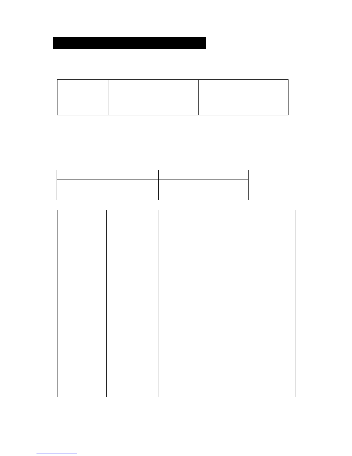
Power
Requirements
RMC100345EE5/CD2
RMC100325EE5/CD2
RMC100345XE5/XD2
RMC1003RSRF
RMC1003RSHST
230-240V ac 50 Hz 13.0A Single Phase 2 Wire + Earth.
220-230V ac 50 Hz 14.2A Single Phase 2 Wire + Earth.
230-240V ac 50 Hz 19.2A Single Phase 2 Wire + Earth.
2 x Single Phase + Earth. See rating plate for full details.
2 x Single Phase + Earth. See rating plate for full details.
Power Output Microwave 100%
Convection
Combination
700W (IEC 705)
3000W
700W + 1500W (EE)
700W + 3000W (XE, RS RF, RS HST)
External
Dimensions
Height
Width
Depth
530 mm (Plus 150 mm minimum clearance above)
550 mm (Plus 50 mm minimum clearance each side)
575 mm (Plus 50 mm clearance behind)
Internal
Dimensions
Height
Width
Depth
Turntable
Capacity
315 mm
330 mm
330 mm
300 mm Diameter
34.3 litres (1.21 ft³)
Weight Nett
Gross packed
45 kg
58 kg
Construction Cavity
Casework
Vitreous Enamel Coated Steel
304 Stainless Steel
Anodised Aluminium Extrusions
Settings Microwave
Temperature
Timer
100%,75%,50%,25%, Convection only
Off, 175°, 200°, 225°, 250°, 275°
Up to 30 minutes
Up to 3 cooking stages of up to 30 minutes each
(Programmed)
Model Number: RMC1003 + Voltage + Frequency + Current + Controls + Extras
PRODUCT SPECIFICATIONS
Model prefix Voltage Frequency Current Control Type
2 = 220-230V a.c.
4 = 230-240V a.c
5 = 50 Hz
6 = 60 Hz
EE=Reduced Cur-
rent
XE = Full
Current
5 = Series 5
controls
RMC1003
ELECTRONIC CONTROLS
Model Number: RMC1003 + Voltage + Frequency + Current
Model prefix Voltage Frequency Current
RMC1003
2 = 220-230V a.c.
4 = 230-240V a.c.
5 = 50 Hz
6 = 60 Hz
CD2 = 13amp
XD2 = 30amp
MANUAL CONTROLS
Rail spec: RMC1003 + RS + Carriage Type RF/HST
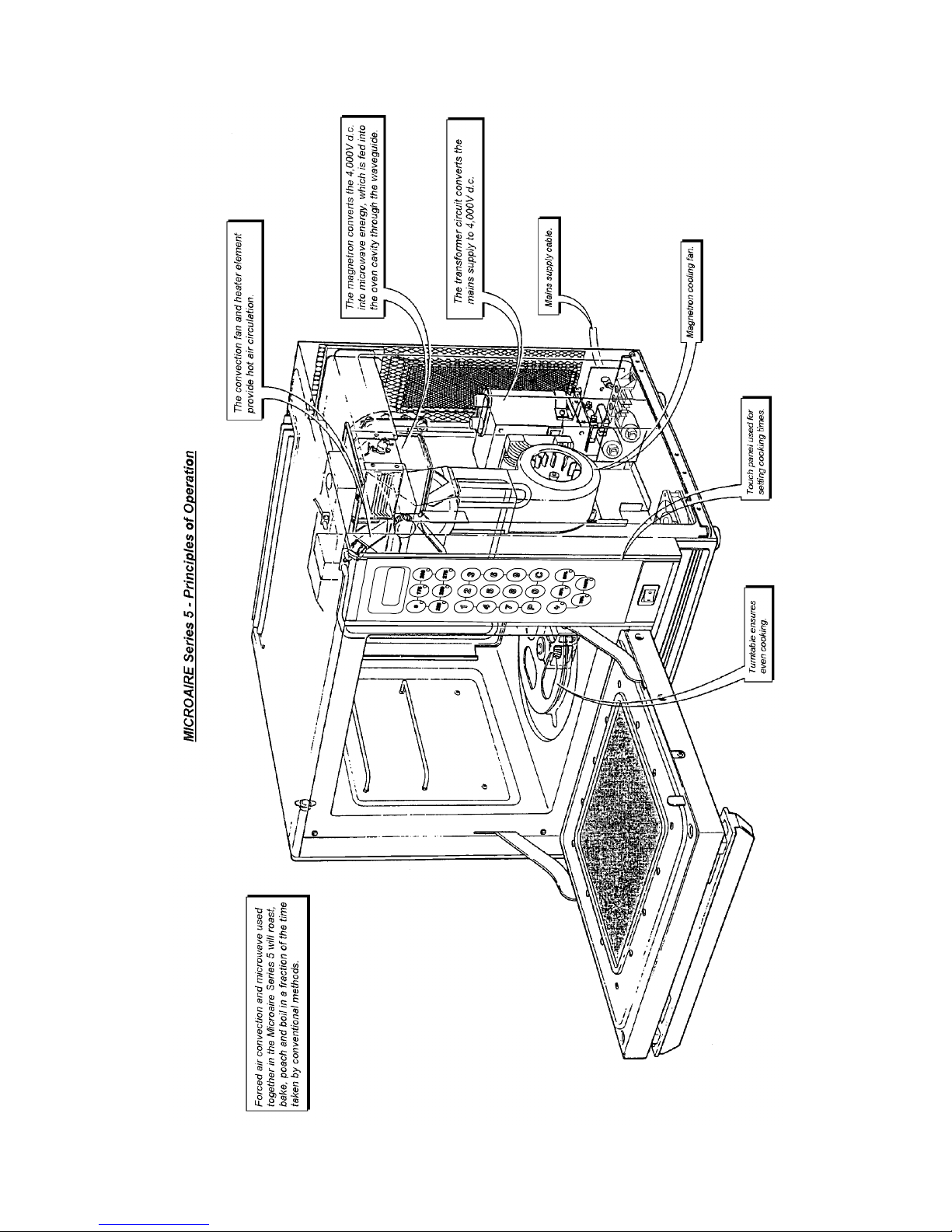
Page 5 Microaire Ovens 32Z3311e Issue 5

Page 6 Microaire Ovens 32Z3311e Issue 5
INSTALLATION INSTRUCTIONS
Positioning the Oven
In order to maintain adequate ventilation for air intake and exhaust, and to allow access for
cleaning filters, you must allow a minim um of 50 mm clearance at the sides and rear of the
oven, and at least 150 mm above. Air intake temperature should not exceed 35°C.
Excessive temperature will lead to reduced operating duty cycle or premature ageing of internal
components.
Power Supply Requirements
The
Microaire Series
should be connected to a suitable electricity supply, which can cope with
the switching-on surge that occurs with certain types of catering equipment, such as
microwaves. Because of this requirement, we strongly recommend that a separate, suitably
rated supply is installed for the oven.
The supply for the oven should be fitted with a
Type "C"
circuit breaker, rated at:
20 Amp for Microaire 13A/ CD² or 30 Amp for Microaire 30A/ XD²
If the oven is hard-wired to the supply, a double-pole isolator switch with a contact gap of at
least 3 mm should be fitted.
Custom ovens for Railway Use only
Microaire Series 5 RS RF and RS HST Power Supply Requirements
These versions of the oven are custom Rail Specification designs for use on two separate
phases of a mains supply, with isolated neutrals and a common earth connection.The full
power supply and circuit breaker requirements for these ovens is listed on the label aff ixed to
the rear of the oven casing.
These ovens are NOT suitable for connection to a standard
mains supply.
NEVER
Install an oven above fryers, grills, griddles or any other major heat source.
NEVER
Stack machines on top of each other - always use a double stand.
ALWAYS
Place containers in the cavity carefully - impact damage may chip the
vitreous enamel coating.
Page 7 Microaire Ovens 32Z3311e Issue 5
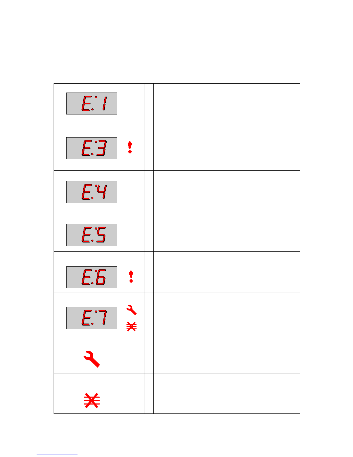
Error Codes and Diagnostics
The Microaire Series 5 will identify some of the most common problems by flashing an error
message code in the time display window.
These are the error messages, and suggestions for repairing them.
1
2
Door not fully shut.
Possible electrical fault
Close door fully.
Door switch inoperative.
1
2
3
No time has been set.
Invalid time has been set.
Invalid program has been
set.
Set a time.
Set a valid time.
Use call-back to check program.
1
2
Oven not heating up.
Possible Heater fault.
Possible Sensor fault.
Check heater fuse.
Confirm operation of heater cir-
cuit.
(RS units) Check slave heater
relay and second supply.
1
Oven Cavity overheating.
Confirm heater relay is operating.
(RS units) Check slave heater
relay .
1
Oven is not at correct
temperature to start program.
Remove food.
Allow oven to reach correct tem perature.
Operator Error !!
1 Magnetron overheating. Check air filters.
Check location, air inlet temperature and air filters.
Note : this will lead to condition
shown below.
1
2
Magnetron has overheated but has now recovered.
Internal diagnostic fault.
Check that magnetron cooling
fan and turntable are working
correctly.
Check installation, air inlet temperature and air filters.
1
Oven control area is
overheating.
Check air filters.
Check axial fan.
Check installation for hot air intake.
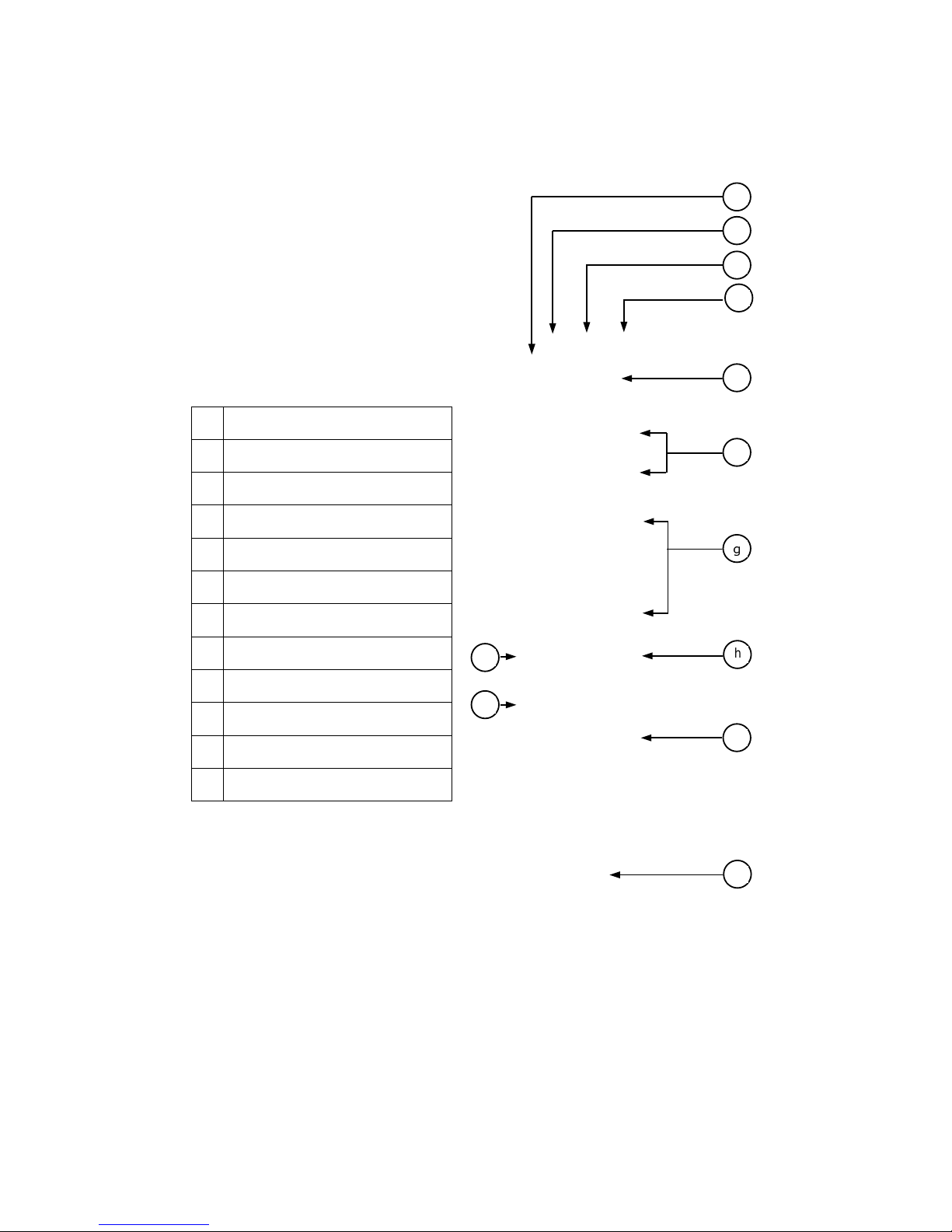
Page 8 Microaire Ovens 32Z3311e Issue 5
a STEAM OUTLET
Allows steam and excess pressure to escape
from the oven cavity. It must be kept clear.
b AIR OUTLET
Hot air is vented here. It must be kept clear.
c TRAY HANDLE RESTS
There is one on each side of the oven for
convenient storage of the tray handle.
d BAFFLE PLATE
Forms the inside rear of the oven and covers
the hot air circulation fan. Removable for
cleaning by unscrewing the four wing nuts
which hold it in place. This must be cleaned on
a regular basis, and kept free of debris.
e RUNNERS
These mounted on each side of the oven
cavity to support the rectangular racks or oven
trays, and are for use in
Convection mode
only
.
f HOT AIR FAN
Situated behind the baffle plate, and circulates
the hot air through the baffle plate, over the
heating element, and around the edge of the
baffle plate back into the cavity.
g OVEN CAVITY
The oven cavity is mainly constructed form
vitreous enamelled steel panels. It must be
kept clean.
h TURNTABLE TRAY
The vitreous enamelled turntable tray fits onto
the turntable disc in the bottom of the oven
cavity, and rotates during cooking to ensure an
even distribution of microwave energy.
i AIR INLETS
Additional air inlets are situated along the lower
edge of the left-hand side panel, and must not
be obstructed.
j RATING PLATE
The rating plate is situated on the rear of the
oven, and states the Model, Serial Number,
Electrical Ratings and Manufacturers tel no.
k DOOR
The door consists of a thermally insulated inner
section, and an additional air gap provided by a
twin skinned door front to lower the surface
temperature.
l ON/OFF SWITCH
This is used to turn the oven On or Off.
IT
DOES NOT ISOLATE INTERNAL WIRING
FROM THE ELECTRICAL SUPPLY
.
m FEET
These feet are fitted to ensure adequate airflow
under the oven. They must not be removed. On
RS units, these are also the means of anchoring
the oven to the work surface.
n ELECTRICAL SUPPLY LEAD
o AIR FILTER (REF 27)
Main intake for cooling air for internal
components. Must be clear of obstructions.
Main Features
a
b
c
d
e
f
g
h
i
j
k
L
m
o
n
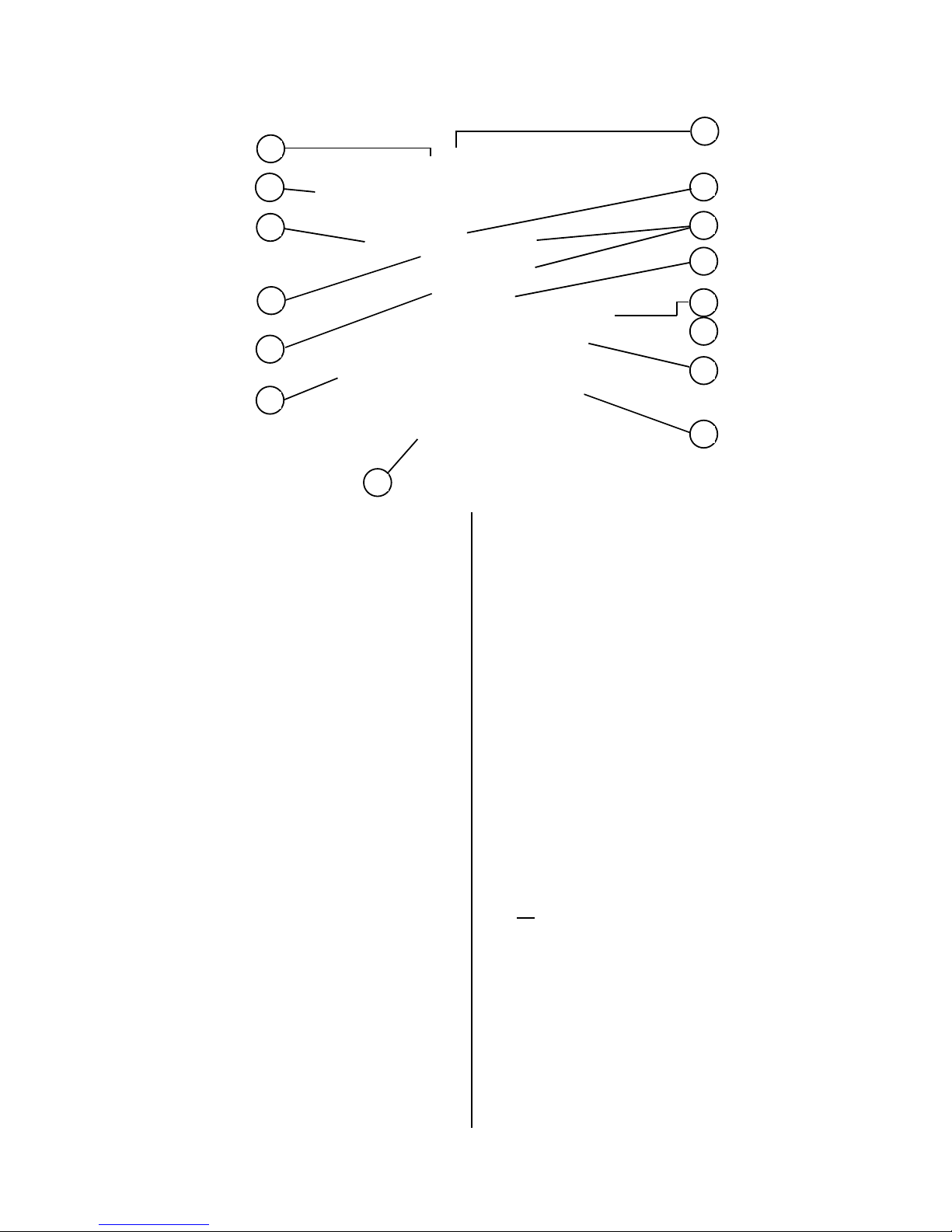
Page 9 Microaire Ovens 32Z3311e Issue 5
a Stage LED's
b Service Indicator
c Air Filter Block Indicator
d Operator error indicator
e Program Display
f Temperature Set Pads
g Time / Precept Pads
h Cancel/ Callback Pad
i Program Pad
j Convection Pad
k Microwave power Pads
L On/Off switch (Ref. No. 97)
a
b
c
e
f
J
h
i
j
k
L
Electronic controls: Microaire Series 5
d
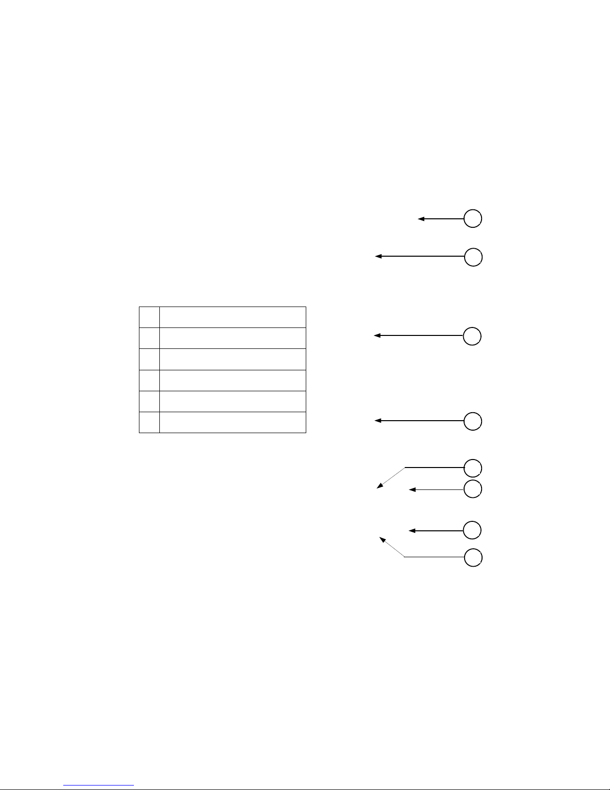
Page 10 Microaire Ovens 32Z3311e Issue 5
a Timer Amber Neon
b Control Knob
c Start Pushbutton
d Cook cycle Red Neon
e Power Amber Neon
f On/Off switch
a
b
e
Manual controls: Model No.s CD2, XD2
b
d
b
c
f
 Loading...