

Page 1

i
© 2006 Mercury Marine SC1000 System Tach/Speedometer and Smart Tow Tachometer
898283002 706
Page 2

ii
Page 3

TABLE OF CONTENTS
iii
Basic Operation and Features
Basic Operation and Features ....................................................1
Master Reset...............................................................................1
Auto Detection Engine Function..................................................2
Display Screens...........................................................................3
Warning System
Alarm Warnings...........................................................................4
Warning Display Screens............................................................5
Warning System with Descriptive Text
Alarm Warnings with Descriptive Text.........................................9
System Speedometer Display Screens
System Speedometer Display Screens.....................................11
System Tachometer Display Screens
System Tachometer Display Screens........................................ 13
Smart Tow Tachometer Display Screens
Cruise Control Operation...........................................................15
Launch Control Operation..........................................................17
Troll Control
Troll Control Operation..............................................................19
Page 4

TABLE OF CONTENTS
iv
Speedometer Calibration
Speedometer Quick CAL Calibration.........................................22
Speedometer CAL 1 Calibration................................................22
Speedometer CAL 2 Calibration ...............................................24
Tachometer Calibration
Tachometer Quick CAL Calibration...........................................26
Tachometer CAL 1 Calibration..................................................26
Tachometer CAL 2 Calibration..................................................30
Page 5
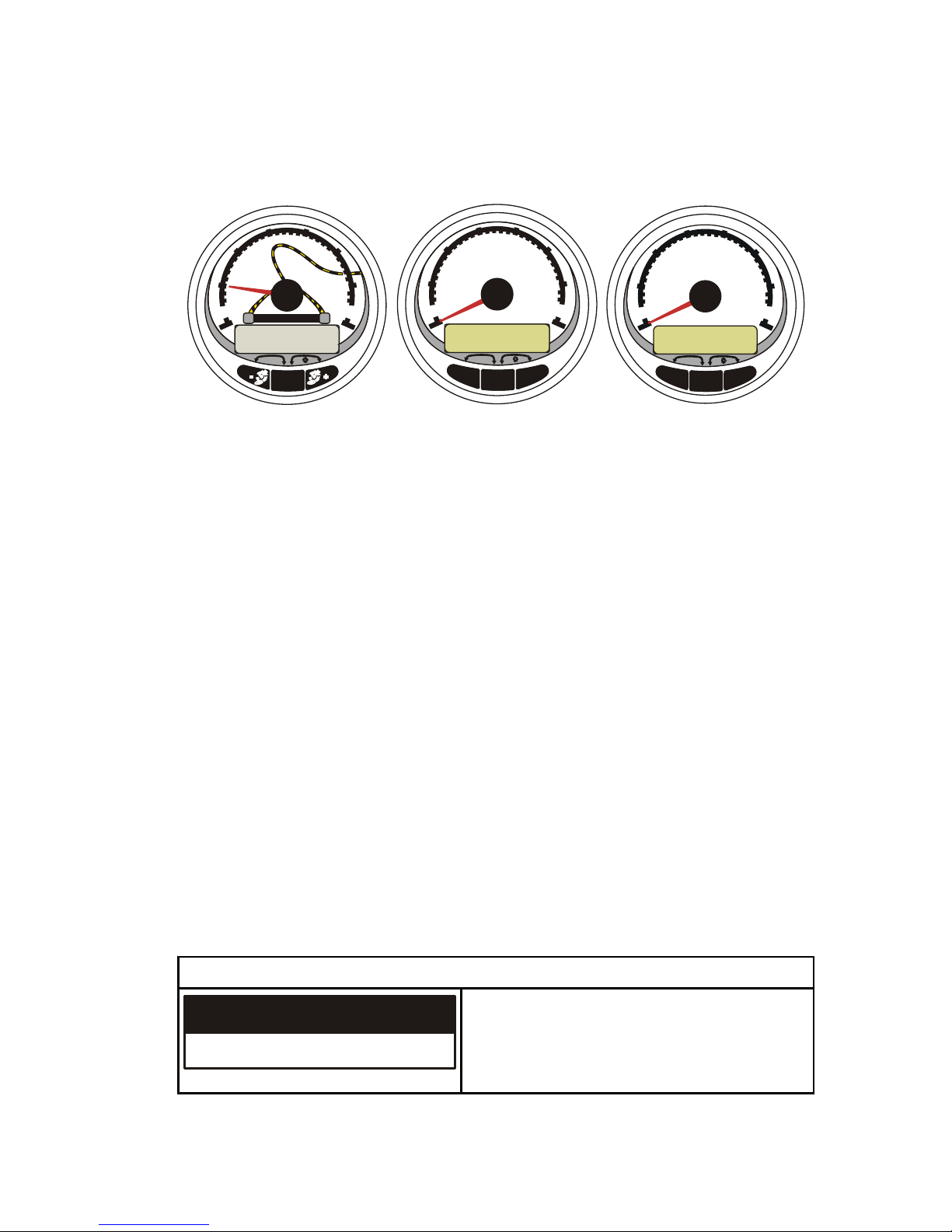
BASIC OPERATION AND FEATURES
1
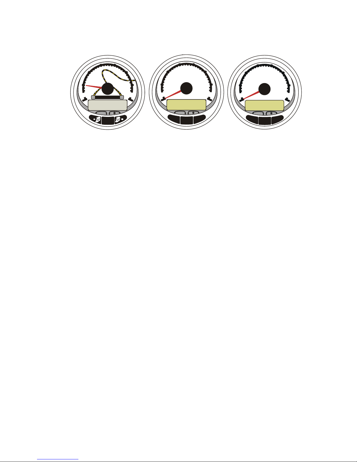
Basic Operation and Features
22642
MODE
RPM x 1000
0
2
3
4
5
6
7
1
RESET
TROLL
+
TROLL
-
SPEED
0
20
30
40
50
60
70
10
RESET
TROLL
-
MODE
+
TROLL
SELECT
0
2
3
4
5
6
7
1
RESET
RPM x 1000
SMART TOW
Smart Tow
Tachometer
System Tachometer System
Speedometer
Power up: Each gauge will power up when the ignition is turned
on. The gauges will stay on as long as the ignition is on.
Lights: Adjusts the brightness and contrast of the gauge.
Buttons: The "MODE/SELECT" button is used for selecting
information screens. The "+" and "-" buttons are used for setting
engine speed during troll, cruise control, and setting gauge
calibrations.
Troll Control: Sets and controls the idle speed of the engine for
trolling without using the throttle. (System Tachometer and
Speedometer).
Cruise Control: Sets and controls the speed of the engine for
cruising. (Smart Tow Tachometer only).
Launch Control: Sets and controls the speed of acceleration from
idle to set cruise speed. (Smart Tow Tachometer only).
Engine Guardian System: Monitors the critical sensors on the
engine for any early indications of problems. The system will
respond to a problem by reducing engine speed and alert the
operator to a potentially damaging situation.
Warning System: The system sounds the warning horn and
displays the warning message.
Master Reset
Returns the gauge to the factory defaults through the Master Reset
command.
Page 6
BASIC OPERATION AND FEATURES
2
IMPORTANT: Performing a master reset will reset the unit to the
factory defaults, thus eliminating any installation and calibrations
performed during set up of product.
Press the "-" and "+" buttons simultaneously for approximately 10
seconds (until the graphic bars collide) to restore the unit to factory
default settings. Press the "MODE/SELECT" button to confirm.
22660
MASTERRESET
MASTERRESET
ERASE CALIBRATION !
PRESS MODE/SELECT TO CONFIRM
Auto Detection Engine Function
The System Tachometer/Speedometer and Smart Tow
Tachometer come standard with an Engine Auto-detection feature.
This feature lets the gauge, on the initial power up, automatically
detect which engine type is used and configure the gauge to match
that engine type.
On first time power up of the gauge or after a Master Reset, the
gauge will display "AUTODETECT". Upon pressing the "MODE/
SELECT" button, the gauge will automatically determine engine
type. This will preset the data monitoring screens accordingly. The
intention is to make initial setup easier. Press the "MODE/
SELECT" button to start the Auto Detection Engine function.
AUTODETECT
ENGINE SMARTSCREEN
PRESS MODE/SELECT TO START
24298
If the gauge shows a warning of "NO STARBOARD ENGINE" or
"MULTIPLE STARBOARD ENGINES", the engine location must
be properly selected (Port and Starboard) at the engine using a
Mercury Computer Diagnostic System tool (CDS). Perform the
Master Reset and Auto Detect functions again. (Refer to Master
Reset).
Page 7
BASIC OPERATION AND FEATURES
3
Computer Diagnostic System (CDS) Order through SPX
4520
Monitors all electrical systems for
proper function, diagnostics, and
calibration purposes. For
additional information, pricing, or
to order the Computer Diagnostic
System contact:
SPX Corporation
28635 Mound Rd.
Warren, MI 48092
or call:
USA - 1-800-345-2233
Canada - 800-345-2233
Europe - 49 6182 959 149
Australia - (03) 9544-6222
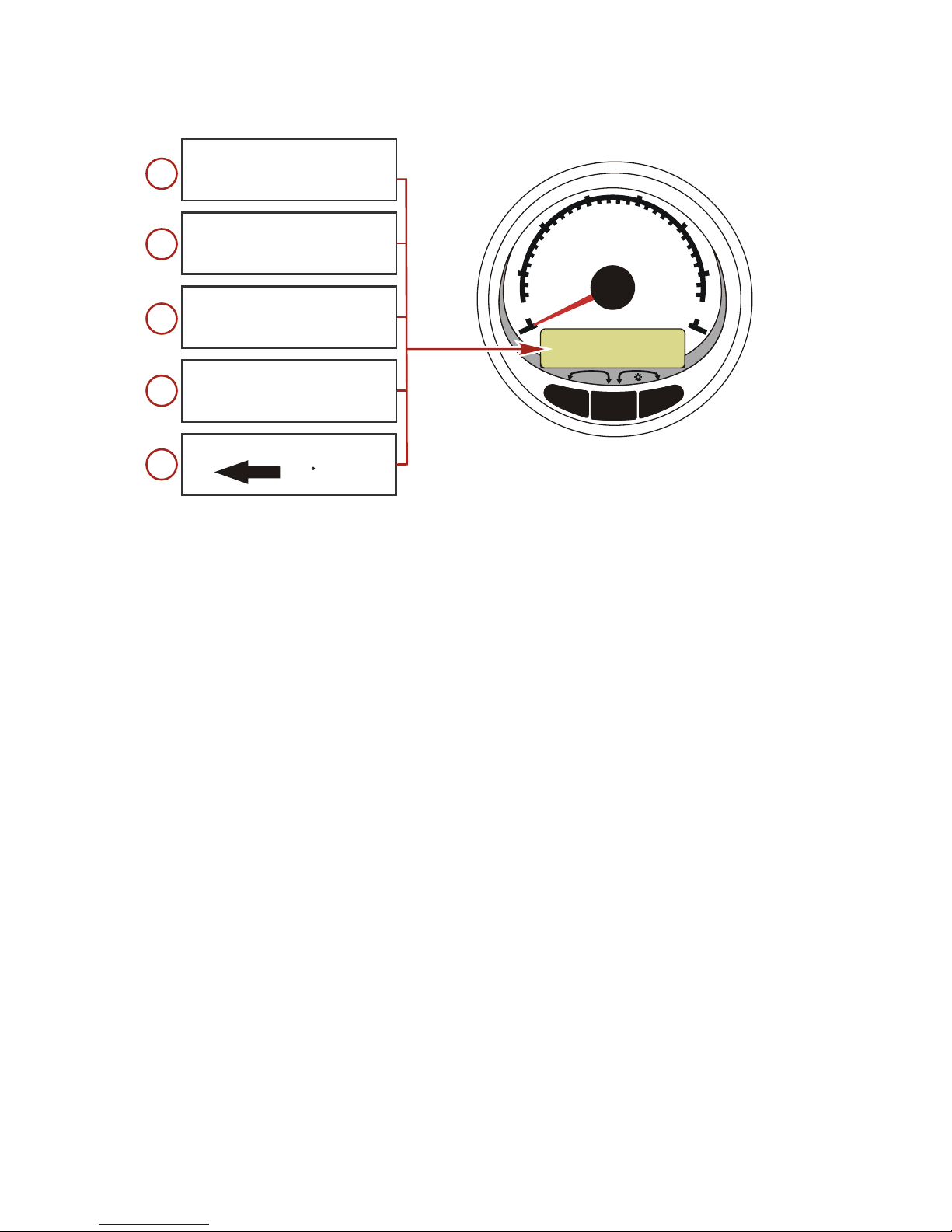
Display Screens
Tachometer Display Screen Speedometer Display Screen
Engine Break-in Speed
Engine Temperature Fuel Used
Oil PSI Cog/Sog - If there is a GPS input
Oil Pressure Distance and fuel to Waypoint
Trim and Water Pressure Clock - Air/Sea Temp
Water Pressure Inst. and Avg. Fuel Economy
Battery Voltage and Engine Hours Trip Odometer
Fuel Flow and Fuel Used Fuel Tank Levels
% Fuel Remaining (Fuel Tank 1) Oil Tank Levels
RPM Fresh Water Levels
Depth Waste Water levels
Speed/Sea Temperature
Dual Engine
Trim and RPM Synchronizer
Fuel Range
Fuel Flow
Trip Odometer
Steering Angle
Page 8
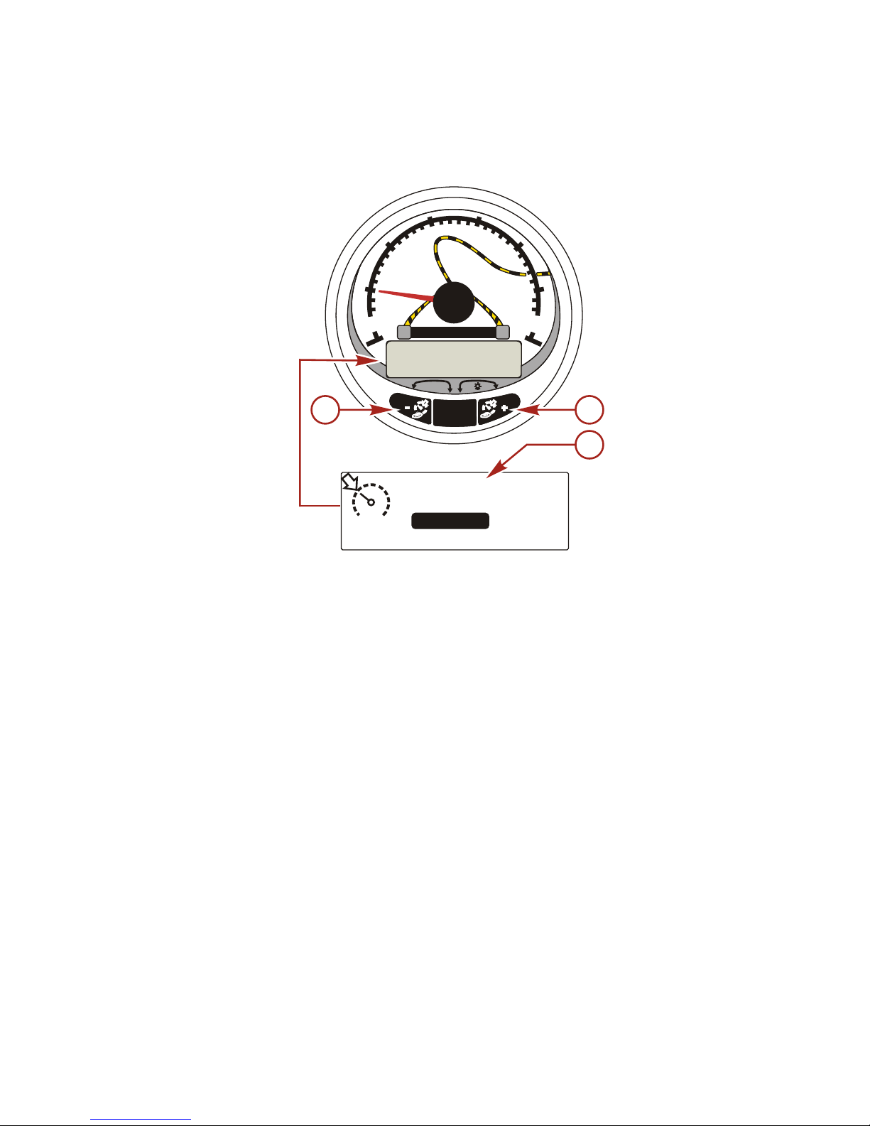
WARNING SYSTEM
4
Alarm Warnings
NOTE: Alarm warnings are displayed as shown when used with
engines prior to Gen I (2007).
3200
RPM
AL
b
c
22663
MODE
RPM x 1000
0
2
3
4
5
6
7
1
RESET
TROLL
+
TROLL
-
MODE
SPEED
0
20
30
40
50
60
70
10
RESET
TROLL
+
TROLL
-
a
REDUCE
THROTTLE
a - Display screen
b - Engine Guardian System
c - Alarm signal
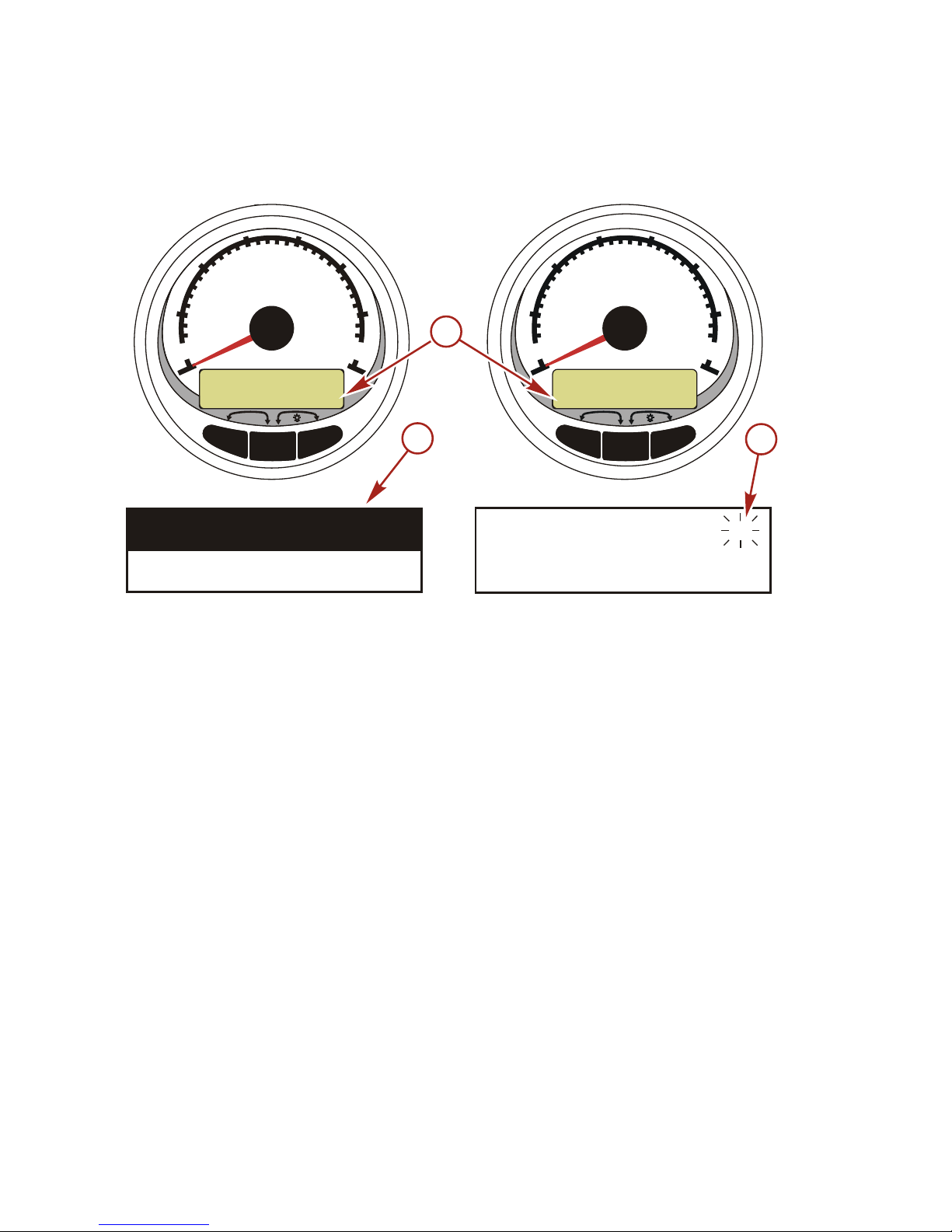
When a problem is detected, the name of the offending alarm
appears on the display.
If problem can cause immediate engine damage, the Engine
Guardian System will respond to the problem by limiting engine
power. Immediately reduce the throttle speed and refer to the
warning messages on the following pages. Refer to the Engine
Operation, Maintenance, and Warranty Manual for further
explanation of the problem and the correct action to take.
The alarm message will stay displayed until the "MODE" button is
pressed. If there are multiple alarms, these will cycle on the display
at five-second intervals.
If the "MODE" button is pressed to display a different screen, the
flashing alarm signal "AL" will appear in the upper right corner to
indicate there still is a problem.
Page 9
WARNING SYSTEM
5
Warning Display Screens
When a problem is detected with the engine, the warning display
screens will alert the operator to the potential problem. Refer to the
Engine Operation, Maintenance, and Warranty Manual for
explanation of the problem and the correct action to take.
PROBLEM TACHOMETER DISPLAY SPEEDOMETER DISPLAY
BATTERY ×
ENGINE DATA BUS ×
FAULT- HORN ×
FAULT- IGNITION ×
FAULT- INJECTOR ×
FAULT- OIL PUMP ×
FAULT- SENSOR ×
FAULT- WATER
TEMP
×
LOW FUEL ×
LOW OIL ×
OIL TEMP ×
OIL PSI ×
OVERHEAT ×
OVER SPEED ×
PRESSURE ×
RESERVE OIL ×
WATER IN FUEL ×
MAP ×
MAT ×
TPS ×
Page 10
WARNING SYSTEM
6
NOTE: Not all screens may apply to your engine type.
MODE
RPM x 1000
0
2
3
4
5
6
7
1
RESET
TROLL
+
TROLL
-
OVERHEAT
PRESSURE
OVERSPEED
WATER
FAULT
RESERVE
FAULT
FAULT
7500
RPM
IN FUEL
HORN
90% REMAINING
OIL PUMP
INJECTOR
22763
1234567
8
IMPORTANT: Refer to the Engine Operation, Maintenance, and
Warranty Manual for further explanation of the problem and the
correct action to take. Contact your dealer if the problem persists.
1. OVERHEAT: The engine has overheated.
2. PRESSURE: There is insufficient water pressure in the
cooling system.
3. OVERSPEED: Engine speed exceeded the maximum
allowable RPM.
4. WATER IN FUEL: Water in the water separating fuel filter
reached the full level.
5. FAULT - HORN: The warning horn is not functioning correctly.
6. RESERVE OIL LOW - 2-STROKE OUTBOARD ONLY: Oil
level is critically low in the engine mounted oil reservoir tank.
7. FAULT - OIL PUMP: The oil pump has stopped functioning
electrically. No lubricating oil is being supplied to the engine.
8. FAULT - INJECTOR: One or more of the fuel injectors have
stopped functioning electronically.
Page 11
WARNING SYSTEM
7
NOTE: Not all screens may apply to your engine type.
MODE
RPM x 1000
0
2
3
4
5
6
7
1
RESET
TROLL
+
TROLL
-
FAULT
BATTERY
FAULT
FAULT
FAULT
FAULT
FAULT
SENSOR
WATER TEMP
OIL TEMP
22892
ENGINE
DATA BUS
IGNITION
NO STARBOARD
ENGINE
MULTIPLE STARBOARD
ENGINE
8V 18V
91011
12
13
14
15
16
9. FAULT - IGNITION: A problem has developed in the ignition
system.
10.BATTERY: The electrical system is not charging or the battery
charge is low.
11.ENGINE DATA BUS: The data communication link between
the tachometer and engine is not connected.
12.FAULT - SENSOR: One of the sensors is not functioning
correctly.
13.FAULT - WATER TEMP: The sensor for measuring outside
lake/sea water temperature is not functioning correctly.
14.NO STARBOARD ENGINE: The instrument does not detect
the starboard engine computer. This usually indicates that no
data is being transferred from the engine's computer to the
gauge. Check the wiring. Make sure both terminator resistors
are installed in the bus. Make sure both ECMs are not
configured for the port location using a DDT or Quicksilver
Diagnostic Tool.
15.MULTIPLE STARBOARD ENGINE: SmartCraft gauges are
recognizing multiple engines as starboard.
NOTE: In multiple engine applications, each engine must first be
assigned a position (starboard, port, starboard2 or port2) with a
Computer Diagnostic Tool (CDS) before the system will function
properly.
16.OIL TEMPERATURE: The engine oil is overheating.
Page 12
WARNING SYSTEM
8
NOTE: Not all screens may apply to your engine type.
MODE
RPM x 1000
0
2
3
4
5
6
7
1
RESET
TROLL
+
TROLL
-
FAULT
LOW FUEL
LOW OIL
FAULT
FAULT
FAULT
MAP
MAT
TPS
OIL PRESSURE
E F
E
F
22897
1718192122
20
17.OIL PRESSURE: There is insufficient oil pressure.
18.LOW FUEL LEVEL The fuel level in the fuel tank is critically
low. Stop for fuel immediately to avoid running out.
19.LOW OIL LEVEL - OUTBOARD 2-STROKE ONLY: The oil
level in the remote oil tank is low. Stop and refill the oil tank
immediately to avoid running out.
20.FAULT - MAP: Engine problem occurred. Have the engine
checked by your dealer.
21.FAULT - MAT: Engine problem occurred. Have the engine
checked by your dealer.
22.FAULT - TPS: Engine problem occurred. Have the engine
checked by your dealer.
Page 13
WARNING SYSTEM WITH DESCRIPTIVE TEXT
9
Alarm Warnings with Descriptive Text
NOTE: Descriptive text alarm warning screens are displayed with
Gen I (2007) engines and newer.
22642
MODE
RPM x 1000
0
2
3
4
5
6
7
1
RESET
TROLL
+
TROLL
-
SPEED
0
20
30
40
50
60
70
10
RESET
TROLL
-
MODE
+
TROLL
SELECT
0
2
3
4
5
6
7
1
RESET
RPM x 1000
SMART TOW
When a problem is detected, the "SYS FAULT" alarm appears on
the display. Press the "+" button to show the faulty component. The
upper bar in this screen displays the system where the fault is
located. The faulty component is described in the scrolling text.
Press the "+" button for more information. This screen gives a
detailed description of the fault in the scrolling text. Press the "+"
button to view the required corrective action.
The alarm message will stay displayed until the "-" button is
pressed. If there are multiple alarms, press the "MODE/SELECT"
button to display.
If problem can cause immediate engine damage, the Engine
Guardian System will respond to the problem by limiting engine
power. Immediately reduce the throttle speed to idle and refer to
the warning messages on the following pages. Refer to the
appropriate service manual for further explanation of the problem
and the correct action to take.
If the "MODE/SELECT" button is pressed to display a different
screen, the flashing alarm signal "AL" will appear in the upper right
corner to indicate there still is a problem.
Alarm Warning with Descriptive Text
[ SHOW ]
SYS FAULT
24184
The "SYS FAULT" bar indicates there is a
problem in the system. "SHOW" displays
the faulty component.
Page 14

WARNING SYSTEM WITH DESCRIPTIVE TEXT
10
Alarm Warning with Descriptive Text
[ MORE ]
[ NEXT ][ EXIT ]
STBD SYSTEM FAULT
<FAULTY COMPONENT>
24186
STBD SYSTEM FAULT
The top bar indicates the system with the
faulty component. The scrolling text
displays the faulty component. "NEXT"
displays the next fault. "MORE" displays a
detailed description of the fault.
[ ACTION ]
[ NEXT ][ EXIT ]
STBD SYSTEM FAULT
<FAULT DESCRIPTION>
24187
The scrolling text explains in detail the
description of the fault. "ACTION" displays
the course of action required by the
operator.
[ BACK ]
[ NEXT ][ EXIT ]
STBD SYSTEM FAULT
<CORRECTIVE ACTION>
24189
The scrolling text displays the course of
action required by the operator.
Page 15

SYSTEM SPEEDOMETER DISPLAY SCREENS
11
System Speedometer Display Screens
NOTE: Not all screens may apply to your engine type.
SPEED
0
20
30
40
50
60
70
10
RESET
TROLL
-
MODE
+
TROLL
5:30 PM
70
60
F
AIR
F
SEA
FUEL
E
F
GALLONS60
OIL
E
F
GALLONS0.6
RPM SYNCH
TRIM SYNCH
STBD
23462
PORT
STBD
PORT
12345
When the ignition is turned on, the speedometer will show the last
screen that was displayed before the ignition was turned off.
Press "MODE" to change display screens. You can revert back to
the previous screen by pressing and holding "MODE" for 2
seconds.
NOTE: Readings can be displayed in English (U.S.) or Metric.
Refer to Speedometer Calibrations.
NOTE: Descriptions are not necessarily in order on the gauge.
Order changes depending on engine type.
1. Clock - Temp: Clock, air temperature and water temperature.
The air and water temperature sensors will have to be
connected to obtain display readings.
2. Fuel Level: Displays the amount of fuel remaining.
3. Oil Level: Displays the amount of engine oil remaining
(Outboard 2-Stroke only), or water/waste tank level (if
attached).
4. RPM Synchronizer: Dual Engines Only - Monitors the
revolutions of both engines.
5. Trim Synchronizer: Dual Engines Only - Displays the trim
position of both engines. Simplifies keeping trim levels equal.
Page 16
SYSTEM SPEEDOMETER DISPLAY SCREENS
12
NOTE: Not all screens may apply to your engine type.
SPEED
0
20
30
40
50
60
70
10
RESET
TROLL
-
MODE
+
TROLL
300
INST M/G AVG
1.5 3.2
23477
ESTIMATED RANGE
MILES
TRIP
25
MILES
42.3
MPH
STEERING ANGLE
52 PORT
678910
6. Range: The estimated range is based on boat speed, fuel
consumption and fuel remaining in the tank. The numbers
displayed indicates an estimate of the distance you can travel
with the remaining fuel. Speed input required (Paddle Wheel,
Pitot Pressure or GPS).
7. Fuel Economy: Displays the average "AVG" fuel
consumption as well as Instantaneous "INST" fuel economy.
The numbers displayed indicate miles per gallon "MPG" or
kilometers per liter "KM/L". Fuel Reset: To reset, select the
display screen and press "MODE" and "-" simultaneously.
8. Trip Odometer: Displays the distance traveled since the
gauge was last reset to zero. Trip Reset: To reset, select the
display screen and press "MODE" and "-" simultaneously
9. Digital Speedometer: Displays the boat speed in miles per
hour, kilometer per hour, or nautical miles per hour. The
speedometer will use the paddle wheel for its low speed
readings but will switch to the speedo or GPS (if connected)
for high speed readings. (Transition point setting is described
in Cal2).
10.Steering Angle: Displays the relative position of the steering
system. Available on Mercury MerCruiser models only. A
steering angle sensor must be installed on the engine.
Page 17

SYSTEM TACHOMETER DISPLAY SCREENS
13
System Tachometer Display Screens
MODE
RPM x 1000
0
2
3
4
5
6
7
1
RESET
TROLL
+
TROLL
-
23495
BREAK-IN TIME
MIN
LEFT
65
OK OK OK
BAT TMP PSI
TRIM WATER PSI
12.51.5
12.5
H20
PSI
F
125
12345
6
TRIM
1.5
When the ignition is turned on, the tachometer will display the last
screen that was displayed before the ignition was turned off.
Press "MODE" to change display screens. You can revert back to
the previous screen by pressing and holding "MODE" for 2
seconds.
NOTE: Readings can be displayed in English (U.S.) or Metric.
Refer to Tachometer Calibration.
1. Engine Break-In: Displays the time remaining on the break-in
period of a new engine. This screen will automatically
disappear after the break-in period is complete.
2. Quick Reference Screen: Indicates that the battery, engine
temperature and pressures are operating properly.
3. Temperature: Displays the engine coolant temperature.
4. Power Trim Angle: Displays the trim angle of the outboard or
sterndrive up to the maximum trim angle and then displays the
trailer angle. 0 = down, 10 = maximum trim, and 25 = full trailer.
5. Power Trim Angle/Water Pressure: Displays the trim angle
of the engine and cooling system water pressure.
6. Water Pressure: Displays the cooling system water pressure
at the engine.
Page 18

SYSTEM TACHOMETER DISPLAY SCREENS
14
NOTE: Not all screens may apply to your engine type.
MODE
RPM x 1000
0
2
3
4
5
6
7
1
RESET
TROLL
+
TROLL
-
23511
OIL
PSI
12.5
VOLTS HOURS
12.2
1.5
RPM
3500
GPH USED
12.5
4.5
FUEL
SPEED SEA TEMP
MPH
45 45
F
7891011
12
35
FT
7. Oil Pressure: Displays the engine oil pressure in "PSI" or
"BAR".
8. Battery Voltage: Displays the voltage level (condition) of the
battery. Also records the running time of the engine.
9. Fuel Flow: Displays the engine fuel use in gallons per hour or
liters per hour.
10.Digital Tachometer: Displays the engine speed in revolutions
per minute (RPM).
11.Water Depth: Displays the depth of water under the
transducer if connected. The water depth screen can be
turned on or off in CAL 1 Calibration. You can set an alarm to
trigger whenever the boat moves into water shallower than the
alarm level. Refer to CAL 2 Calibration for water depth alarm
and offset settings.
NOTE: A depth transducer (purchased separately) must be
connected to the system in order for this screen to operate.
12.Speed/Temp:Displays a split screen of water temperature
and vessel speed.
NOTE: A speed input sensor must be installed (purchased
separately).
Page 19
SMART TOW TACHOMETER DISPLAY SCREENS
15
Cruise Control Operation
NOTE: Cruise control is only available with Gen I (2007) and newer
engines.
SELECT
0
2
3
4
5
6
7
1
RESET
RPM x 1000
SMART TOW
b
a
SMART
TOW ON
1000
CRUISE
LAUNCH
+ / - TO DISENGAGE
RPM SET
c
23186
a - Increase set cruise speed
b - Decrease set cruise speed
c - Set cruise speed
NOTE: Cruise control min/max range may change depending on
engine type.
Set the cruise control speed in RPM by using the Smart Tow
tachometer.
The cruise control can be shut off at anytime by pushing the "+"
and "-" buttons simultaneously.
When the cruise control is engaged and the the throttle is moved
below the set cruise speed, engine RPM will decrease with throttle
movement. When the throttle is moved above the set cruise speed,
the cruise control will actively control the engine speed to the set
cruise speed.
When the cruise control is disengaged it will remember the set
speed. It will return to that speed when the cruise control is
re-engaged and the throttle is positioned beyond the set cruise
speed.
Page 20

SMART TOW TACHOMETER DISPLAY SCREENS
16
Press "SELECT" twice to exit the cruise control screen.
TURNING THE SYSTEM ON/OFF
SELECT
0
2
3
4
5
6
7
1
RESET
RPM x 1000
SMART TOW
b
a
SMART
TOW ON
1000
CRUISE
LAUNCH
+ / - TO DISENGAGE
RPM SET
c
24183
SMART
TOW OFF
1000
CRUISE
LAUNCH
+ / - TO DISENGAGE
RPM SET
d
a - Increase set cruise speed
b - Decrease set cruise speed
c - Set cruise speed
d - Cruise control off
SETTING CRUISE CONTROL
To set the cruise control speed:
1. Push either the "+" or "-" button to bring up the cruise control
display screen.
2. Set desired cruise RPM. When the throttle is in the wide open
position the set RPM will be the maximum speed.
3. Push "+" and "-" button simultaneously to engage the cruise
control.
CANCELING CRUISE CONTROL
To cancel the cruise control: press the "+" and "-" buttons
simultaneously.
Page 21

SMART TOW TACHOMETER DISPLAY SCREENS
17
Launch Control Operation
NOTE: Launch control is only available with Gen I (2007) and
newer engines.
SMART
TOW ON
1000 2
+ / - TO DISENGAGE
RPM
SET LAUNCH
23712
SELECT
0
2
3
4
5
6
7
1
RESET
RPM x 1000
SMART TOW
b
a
d
c
a - Raise launch control setting
b - Lower launch control setting
c - Set cruise RPM
d - Launch control setting
BASIC OPERATION
Launch control determines how fast the engine accelerates to a
set cruise speed.
Set the launch control by using the Smart Tow tachometer. The
settings are 1 through 5, with 1 being the most gradual acceleration
and 5 being the most aggressive. Press "+" to increase launch
control setting and "-" to decrease launch control setting. The
launch control setting will remain until changed.
Page 22

SMART TOW TACHOMETER DISPLAY SCREENS
18
SETTING LAUNCH CONTROL
23481
1. Press "+" or "-" to bring up the cruise control display screen.
2. Push the "SELECT" button to highlight "SET LAUNCH".
3. Push "+" to raise the setting and push "-" to lower the setting.
4. Launch control will automatically turn on with the cruise
control.
If the cruise control is engaged and none of the numerical launch
control settings are selected, ("CRUISE" is displayed) launch
acceleration is controlled by the throttle up to the RPM set point.
The display screen will revert back to the "RPM SET" screen after
5 seconds of inactivity. Push the "+" or "-" buttons to reactivate the
cruise control display screen.
CANCELING LAUNCH CONTROL
The launch control will turn off when the cruise control is turned off.
Page 23
TROLL CONTROL
19
Troll Control Operation
NOTE: The troll control feature is only available on the System
Tach/Speedometer.
MODE
SPEED
0
20
30
40
50
60
70
10
RESET
MODE
RPM x 1000
0
2
3
4
5
6
7
1
RESET
a
a
Troll Speed On
10.5
ACT
MPH
12.0
PUSH SELECT TO DISENGAGE
SET
MPH
f
e
Troll Speed On
1000
ACT
RPM
1500
PUSH SELECT TO DISENGAGE
SET
RPM
d
c
23062
F
AIR
F
SEA70 62
10:35
TR
b
b
a - Increase troll speed
b - Decrease troll speed
c - Actual RPM
d - Set RPM
e - Actual MPH
f - Set MPH
NOTE: Troll control may not be available on all engine models.
NOTE: Troll control min/max range may change depending on
engine type.
Set the troll control by using either the System Tach/Speedometer.
(The Smart Tow Tachometer controls cruise only.) The
speedometer will set the speed in MPH, KPH, or KN while the
tachometer will set the speed in RPM.
The troll control can be shut off at anytime by adjusting the throttle
or by pushing the "MODE" button when in the troll display screen.
When the troll control is shut off, the system will remember the set
speed. When the troll control is re-engaged, it will return to the set
speed.
Page 24

TROLL CONTROL
20
The display screen will revert back to the previous screen after 5
seconds of inactivity. Push the "+" or "-" button to reactivate the
troll control display screen.
When the troll control is engaged and not in the troll control display
screen, a flashing "TR" signal will appear in the upper left corner
of the screen to indicate the troll control is still active.
SETTING TROLL CONTROL
MODE
RPM x 1000
0
2
3
4
5
6
7
1
RESET
TROLL
+
TROLL
-
SPEED
0
20
30
40
50
60
70
10
RESET
TROLL
-
MODE
+
TROLL
600
575
PUSH SELECT TO DISENGAGE
TROLL SPEED ON OFF
ACT
RPM
SET
RPM
TROLL SPEED ON OFF
PUSH SELECT TO DISENGAGE
3.0
2.5
ACT
MPH
SET
MPH
SET
MPH
TROLL SPEED TOO FAST
REDUCE TROLL SPEED
7.5
4.5
ACT
MPH
SET
MPH
TROLL SPEED TOO SLOW
INCREASE TROLL SPEED
3.0
2.5
ACT
MPH
c
d
23035
a
a
f
e
b
b
a - Increase troll set speed
b - Decrease troll set speed
c - Setting is too fast, reduce set troll speed
d - Setting is too slow, increase set troll speed
1. With the engine running, shift the engine into gear. Set the
engine speed at idle.
2. Push in either the "+" or "-" buttons to bring up the troll control
display screen.
3. Press "MODE" to engage the troll control.
Page 25

TROLL CONTROL
21
4. Use the "+" and "-" buttons to set the desired speed. Use "+"
to increase the set speed and use "-" to decrease the set
speed.
5. If the troll speed is set to a higher speed than the troll control
can maintain, the "TROLL SPEED TOO FAST" display will
appear. Reduce the set troll speed.
6. If the troll speed is set to a slower speed than the troll control
can maintain, the "TROLL SPEED TOO SLOW" display will
appear. Increase the set troll speed.
CANCELING TROLL CONTROL
There are three ways to cancel the troll control:
• Press the "MODE" button when in the troll display screen.
• Move the throttle to a different speed.
• Shift the engine into neutral.
Page 26

SPEEDOMETER CALIBRATION
22
Speedometer Quick CAL Calibration
SPEED
0
20
30
40
50
60
70
10
RESET
TROLL
-
MODE
+
TROLL
24159
SC1000 System Speedometer
This calibration is for setting the lighting and contrast.
1. Press the "MODE" and "+" buttons simultaneously for two
seconds to bring up the Quick Cal display screen.
2. Press the "-" or "+" button to select the option choice displayed
in the [ ] brackets on the screen.
3. Press "MODE" ["SAVE"] to save the setting and advance
through the calibration selections.
Quick CAL
LIGHT
(DOWN)
(SAVE) ( UP )
23517
Adjusts the brightness of the gauge lighting.
CONTRAST
(DOWN)
(SAVE) ( UP )
23519
Adjusts the contrast of the display screen.
Speedometer CAL 1 Calibration
This calibration allows you to turn on and off the system display
screens.
NOTE: Screens may vary depending on your engine type.
1. Press the "MODE" and "+" buttons simultaneously for
approximately six seconds to bring up the Cal 1 display
screen.
Page 27

SPEEDOMETER CALIBRATION
23
2. Press the "-" or "+" button to select the option choice displayed
in the [ ] brackets on the screen.
3. Press "MODE" ["SAVE"] to save the setting and advance
through the calibration selections.
REMOTE LIGHTING AND CONTRAST
[ NO ]
[SAVE] [YES ]
23532
REMOTE LCD LIGHT ?
Adjusts the lighting levels on all gauges
simultaneously from this gauge.
[ NO ]
[SAVE] [YES ]
23533
REMOTE LCD CONTRAST ?
Adjusts the contrast of another System Tach/
Speed simultaneously from this gauge.
TIME
( NO )
( SKIP ) ( EDIT )
23534
CALIBRATION 1
TIME
Sets the time. Select "EDIT" to format the time
or "SKIP" to advance to the next screen.
(DOWN)
(SAVE) ( UP )
23535
CALIBRATION 1
TIME FORMAT
12H - M, D, Y
Formats the time as either 12 hour month-dayyear or as 24 hour day-month-year. Select
"DOWN" or "UP" to change the format.
(DOWN)
(SAVE) ( UP )
23536
CALIBRATION HOUR
1:42
PM
Adjusts the hours to match your local time.
Select "DOWN" or "UP" to change the hour
setting.
(DOWN)
(SAVE) ( UP )
23538
CALIBRATION MINUTE
1:42
PM
Adjusts the minutes to match your local time.
Select "DOWN" or "UP" to change the minute
setting.
DISPLAY UNITS
[DOWN]
[SAVE]
[ UP ]
23539
DISPLAY UNITS
ENGLISH
Changes units of measurement between
English (standard) or Metric. Select "DOWN" or
"UP" to change between English or Metric units.
23540
SPEED UNITS
MPH
[DOWN]
[SAVE]
[ UP ]
Changes the units in which speed is displayed.
Choose from: MPH (Miles Per Hour), KN
(Knots), or KMH (Kilometers Per Hour).
Page 28
SPEEDOMETER CALIBRATION
24
DISPLAY SCREENS
[ NO ]
[SAVE] [ YES ]
23542
STEERING ANG. SCREEN ?
YES
The steering angle is displayed ("YES") or off
("NO"). The steering angle sensor must be set
to "YES" in the tachometer "CAL 2" external
sensors calibration.
23543
TEMP/CLOCK SCREEN ?
YES
[ NO ]
[SAVE] [ YES ]
The split screen showing air temperature and
time is displayed ("YES") or off ("NO").
( NO )
(SAVE)
( YES )
23544
FUEL USED SCREEN ?
YES
The fuel used screen is displayed ("YES") or off
("NO").
( NO )
(SAVE)
( YES )
23545
TRIP SCREEN
YES
The trip screen is displayed ("YES") or off
("NO").
( NO )
(SAVE)
( YES )
23546
FUEL MGMNT SCREEN
YES
The fuel management screen is displayed
("YES") or off ("NO").
SIMULATOR MODE
[ NO ]
[SAVE] [ YES ]
23547
SIMULATOR MODE
NO
Enables the simulation mode. (Used for
demonstration purposes only).
EXIT
[ NO ]
[ YES ] [CAL 2]
23549
SIMULATOR MODE
EXIT ?
Press "MODE" to exit. Press "-" to go to the start
of CAL 1. Press "+" to continue to CAL 2.
Speedometer CAL 2 Calibration
This calibration lets you configure the system sensor inputs.
NOTE: Screens may vary depending upon the version of the gauge
and your engine type.
1. Press and hold the "MODE" and "+" buttons simultaneously
for approximately nine seconds until the "CAL 2" display
screen appears.
Page 29

SPEEDOMETER CALIBRATION
25
2. Press the "-" or "+" button to select the option choice displayed
in the [ ] brackets on the screen.
3. Press "MODE" ["SAVE"] to save the setting and advance
through the calibration selections.
EXTERNAL SENSORS
(SKIP) (EDIT)
23569
CALIBRATION 2
EXTERNAL SENSORS
Selects and calibrates external sensors that are
installed in the system. Select [SKIP] for to
proceed to the next selection. Select [EDIT] to
proceed to external sensor selection.
(SAVE) ( YES )
23574
CALIBRATION 2
EXTERNAL SENSORS
( NO )
AIRTEMP ?
YES
Is an air temperature sensor installed? Press "-"
to select no or "+" to select yes.
(SAVE) ( YES )
23582
CALIBRATION 2
EXTERNAL SENSORS
( NO )
GPS ?
YES
Is a GPS sensor installed? Press "-" to select no
or "+" to select yes.
(SAVE) ( YES )
23596
CALIBRATION 2
EXTERNAL SENSORS
( NO )
USE GPS SPEED ? YES
Use the GPS input to drive the speed display?
Press "-" to select no or "+" to select yes.
(SAVE) ( UP )
23592
CALIBRATION 2
SEA TEMP
(DOWN)
OFFSET = 0 F
Adjust the water temperature sensor to correct
display readings that are too high/low. Press "-"
or "+" to calibrate the temperature display down
or up.
(SAVE) ( YES )
23617
CALIBRATION 2
TROLL CONTROL ?
( NO )
ENABLED
To enable troll control select "YES" to disable
select "NO".
(SAVE) ( YES )
23618
CALIBRATION 2
( NO )
EXIT ?
Press "MODE" to exit. Press "-" to go to the start
of CAL 2. Press "+" to continue to CAL 1.
Page 30

TACHOMETER CALIBRATION
26
Tachometer Quick CAL Calibration
SELECT
0
2
3
4
5
6
7
1
RESET
RPM x 1000
SMART TOW
MODE
RPM x 1000
0
2
3
4
5
6
7
1
RESET
TROLL
+
TROLL
-
24157
SC1000 Smart Tow
Tachometer
SC1000 System Tachometer
This calibration is for setting lighting and contrast.
1. Press the "MODE/SELECT" and "+" buttons simultaneously
for approximately two seconds or until the "QUICK CAL"
screen appears.
2. Press the "-" or "+" button to select the option choice displayed
in the [ ] brackets on the screen.
3. Press "MODE/SELECT" ["SAVE"] to save the setting and
advance through the calibration screens.
Quick CAL
LIGHT
(DOWN)
(SAVE) ( UP )
23517
Adjusts the brightness of the gauge lighting.
CONTRAST
(DOWN)
(SAVE) ( UP )
23519
Adjusts the contrast of the display screen.
Tachometer CAL 1 Calibration
This calibration lets you turn the system screens on and off.
NOTE: The screens may vary depending upon the version of the
gauge.
Page 31

TACHOMETER CALIBRATION
27
1. Press and hold the "MODE/SELECT" and "+" buttons for
approximately seven seconds until the "CAL 1" screen
appears.
2. Press the "-" or "+" button to select the option choice displayed
in the [ ] brackets on the screen.
3. Press "MODE/SELECT" ["SAVE"] to save the setting and
advance through the calibration screens.
Tachometer CAL 1 Calibration - Remote Light and Contrast
[SAVE] [ YES ]
23620
REMOTE SCREENS ?
[ NO ]
If "YES" is selected, then screen changes made
on this tachometer will effect all tachometers in
the system. All tachometers need the screen set
to "YES" for this function to work.
[ NO ]
[SAVE] [YES ]
23532
REMOTE LCD LIGHT ?
Adjusts the lighting levels on all gauges
simultaneously from this gauge. If "YES" is
selected, then lighting levels changes made on
this tachometer will effect all tachometers in the
system. All tachometers need the screen set to
"YES" for this function to work.
[ NO ]
[SAVE] [YES ]
23533
REMOTE LCD CONTRAST ?
Adjusts the contrast of another System/Smart
Tow Tachometer simultaneously from this
gauge. If "YES" is selected, then contrast level
changes made on this tachometer will effect all
tachometers in the system. All tachometers
need the screen set to "YES" for this function to
work.
Tachometer CAL 1 Calibration - Trim
[SAVE] [ YES ]
23621
HIGH RESOLUTION TRIM ?
[ NO ]
Enables the trim angle to be displayed in 0.1°
increments if "YES" is selected.
[SAVE] [ YES ]
23641
TRIM POPUP ?
[ NO ]
The trim display screen pops up when the trim
setting is changed if "YES" is selected.
TRIM CALIBRATION
CALIBRATION 1
[SKIP] [EDIT]
23910
Select "EDIT" to calibrate the gauge to the
standard 0 - 10° unit trim and 11 - 25° trailer
position scale. Select "SKIP" to advance to the
next selection.
Page 32

TACHOMETER CALIBRATION
28
Tachometer CAL 1 Calibration - Trim
TRIM FULL DOWN
CALIBRATION 1
THEN PRESS PLUS BUTTON
[DFLT]
[SKIP] [SAVE]
23911
Trim the system to the full down position then
press the "+" button to save the setting.
TRIM FULL UP
CALIBRATION 1
THEN PRESS PLUS BUTTON
[DFLT]
[SKIP] [SAVE]
23912
Trim the system to the up position then press
the "+" button to save the setting.
TRIM TO TRAILER POINT
CALIBRATION 1
THEN PRESS PLUS BUTTON
[DFLT]
[SKIP] [SAVE]
23919
Trim the system to the trailer point then press
the "+" button to save the setting.
Tachometer CAL 1 Calibration - Display Units
[DOWN]
[SAVE]
[ UP ]
23539
DISPLAY UNITS
ENGLISH
Changes units of measure between English
(standard) or Metric. Select "DOWN" or "UP" to
change between "ENGLISH" or "METRIC" units
of measure.
23540
SPEED UNITS
MPH
[DOWN]
[SAVE]
[ UP ]
Changes the units in which speed is displayed.
Choose from: MPH (Miles Per Hour), KN
(Knots), or KMH (Kilometers Per Hour).
Tachometer CAL 1 Calibration - Display Screens
QUICK REF SCREEN ?
[ NO ]
[SAVE] [ YES ]
23978
The quick reference screen is displayed ("YES")
or off ("NO").
ENGINE TEMP SCREEN ?
[ NO ]
[SAVE] [ YES ]
23783
The engine temperature screen is displayed
("YES") or off ("NO").
OIL TEMP SCREEN ?
[ NO ]
[SAVE] [ YES ]
23786
The oil temperature screen is displayed ("YES")
or off ("NO").
OIL PRESS SCREEN ?
[ NO ]
[SAVE] [ YES ]
23787
The oil pressure screen is displayed ("YES") or
off ("NO").
Page 33
TACHOMETER CALIBRATION
29
Tachometer CAL 1 Calibration - Display Screens
TRIM AND PSI SCREEN ?
[ NO ]
[SAVE] [ YES ]
23788
The split screen showing trim angle and water
pressure is displayed ("YES") or off ("NO").
WATER PSI SCREEN ?
[ NO ]
[SAVE] [ YES ]
23789
The water pressure screen is displayed ("YES")
or off ("NO").
TRIM AND RPM SCREEN ?
[ NO ]
[SAVE] [ YES ]
23979
The split screen showing trim angle and engine
RPM is displayed ("YES") or off ("NO").
RPM SCREEN ?
[ NO ]
[SAVE] [ YES ]
23980
The engine RPM screen is displayed ("YES") or
off ("NO").
FUEL USED SCREEN ?
[ NO ]
[SAVE] [ YES ]
23981
The fuel used screen is displayed ("YES") or off
("NO").
VOLT / HOUR SCREEN ?
[ NO ]
[SAVE] [ YES ]
23982
The split screen showing volts and engine hours
is displayed ("YES") or off ("NO").
SPEED / SEA SCREEN ?
[ NO ]
[SAVE] [ YES ]
23983
The split screen showing speed and sea
temperature is displayed ("YES") or off ("NO").
DEPTH SCREEN ?
[ NO ]
[SAVE] [ YES ]
23984
The depth screen is displayed ("YES") or off
("NO").
[ NO ]
[SAVE] [ YES ]
23547
SIMULATOR MODE
NO
Enables the simulation mode. (Used for
demonstration purposes only).
[ NO ]
[ YES ] [CAL 2]
23549
SIMULATOR MODE
EXIT ?
Press "MODE/SELECT" to exit. Press "-" to go
to the start of CAL 1. Press "+" to continue to
CAL 2.
Page 34

TACHOMETER CALIBRATION
30
Tachometer CAL 2 Calibration
This calibration configures the system sensor inputs.
NOTE: The screens may vary depending upon the version of the
gauge.
1. Press and hold the "MODE/SELECT" and "+" buttons for
approximately ten seconds until the "CAL 2" screen appears.
2. Press the "-" or "+" button to select the option choice displayed
in the [ ] brackets on the screen.
3. Press "MODE/SELECT" ["SAVE"] to save the setting and
advance through the calibration screens.
FUEL TANK CALIBRATION
There are three methods for calibrating the fuel tank level
monitoring feature:
1. Do nothing. The linear readout is based on raw sensor values.
This mode does not factor in irregular tank shapes.
2. By performing the following tank calibration procedure, but
without actually adding fuel. The System Tachometer/Smart
Tow Tachometer will supply an estimated range value based
on linear interpolation of the sensor range values. This mode
does not factor in irregular tank shapes.
3. By performing the following tank calibration procedure
completely, which means adding fuel at each calibration point.
The System Tachometer/Smart Tow Tachometer will display
an estimated range value that factors in the tank shape.
CAL2 Tachometer Calibration - Tank 1 and 2 Level Calibration
FUEL TANK 1 CAPACITY
CALIBRATION 2
CAPACITY = 26.2 G
[DOWN]
[SAVE] [ UP ]
23992
Enter the capacity of the tank. Select "DOWN"
or "UP" to set the tank capacity. Then press
"SAVE". This option is the same for tank 1 as it
is for tank 2.
FUEL TANK 1
CALIBRATION 2
[SKIP] [EDIT]
23993
Select "EDIT" to enter the calibration mode of
the fuel tank. The calibration procedure is the
same for tank 1 as it is for tank 2. Select "EDIT"
to begin tank level calibration.
DEFAULT CALIBRATION,
TANK CALIBRATION :
OR ADD FUEL ?
[DFLT]
[ADD ]
23994
Select "DFLT" to let SmartCraft calibrate the
tank levels. Select "ADD" to calibrate the tank
levels by adding fluid to the tank.
Page 35

TACHOMETER CALIBRATION
31
CAL2 Tachometer Calibration - Tank 1 and 2 Level Calibration
EMPTY TANK
CALIBRATING :
THEN PRESS PLUS BUTTON
[SKIP]
[SAVE]
23995
Empty the tank. Select "SAVE" to calibrate the
tank level to empty.
FILL TO 1/4
CALIBRATING :
THEN PRESS PLUS BUTTON
[SKIP]
[SAVE]
24002
Fill the tank to 1/4 full. Select "SAVE" to calibrate
the tank level to 1/4 full.
FILL TO ½
CALIBRATING :
THEN PRESS PLUS BUTTON
[SKIP]
[SAVE]
24003
Fill the tank to 1/2 full. Select "SAVE" to calibrate
the tank level to 1/2 full.
FILL TO 3/4
CALIBRATING :
THEN PRESS PLUS BUTTON
[SKIP]
[SAVE]
24004
Fill the tank to 3/4 full. Select "SAVE" to calibrate
the tank level to 3/4 full.
FILL TO FULL
CALIBRATING :
THEN PRESS PLUS BUTTON
[SKIP]
[SAVE]
24005
Fill the tank to full. Select "SAVE" to calibrate
the tank level to full.
TANK 2 INPUT
OIL TANK
CALIBRATION 2
[SAVE][DOWN]
[ UP ]
24148
Select tank 2 input: oil tank, fuel tank 2, water
tank, waste tank, or not installed.
EXTERNAL SENSORS
CAL2 Tachometer Calibration - External Sensors
EXTERNAL SENSORS ?
CALIBRATION 2
[SKIP]
[EDIT]
24006
Selects and calibrates external sensors that are
installed in the system. Select [SKIP] to proceed
to the speed options. Select [EDIT] to proceed
to external sensor selection.
EXTERNAL SENSORS
CALIBRATION 2
PITOT SENSOR ? YES
[ NO ]
[SAVE] [YES ]
24007
Is the boat equipped with a pitot sensor to
measure boat speed? Press "-" to select no or
"+" to select yes.
EXTERNAL SENSORS
CALIBRATION 2
PADDLE SENSOR ? YES
[ NO ]
[SAVE] [YES ]
24008
Is the boat equipped with a paddle wheel to
measure boat speed? Press "-" to select no or
"+" to select yes.
Page 36
TACHOMETER CALIBRATION
32
CAL2 Tachometer Calibration - External Sensors
EXTERNAL SENSORS
CALIBRATION 2
TRIM SENSOR ? YES
[ NO ]
[SAVE] [YES ]
24009
Is the boat equipped with a trim sensor? Press
"-" to select no or "+" to select yes.
EXTERNAL SENSORS
CALIBRATION 2
SEA TEMP ?
[ NO ]
[SAVE] [YES ]
24010
YES
Is the boat equipped with a water temperature
sensor? Press "-" to select no or "+" to select
yes.
EXTERNAL SENSORS
CALIBRATION 2
STEERING SENSOR ?
[ NO ]
[SAVE] [YES ]
24011
YES
Is the boat equipped with a steering sensor?
Press "-" to select no or "+" to select yes.
SPEED OPTION
CALIBRATION 2
[SKIP] [EDIT]
24012
This section configures the following speed
sensors. Select "EDIT" to calibrate the sensors.
Select "SKIP" to proceed to the depth sensor
screen.
PITOT SENSOR
100 PSI TYPE
CALIBRATION 2
[ NO ]
[SAVE] [YES ]
24014
Select pitot transducer type. Choose between
100 or 200 psi. (100 psi is the most common)
PITOT SENSOR
CALIBRATION 2
[DOWN]
[SAVE] [ UP ]
24018
MULTIPLIER = 1.00
Adjust the pitot pressure sensor to correct
display readings that are too high/low. Press "-"
or "+" to calibrate the pitot sensor multiplier
down or up.
PADDLE SENSOR
CALIBRATION 2
[DOWN]
[SAVE] [ UP ]
24021
PULSEFACTOR = 3.0
Adjust paddle wheel frequency to correct
display readings that are too high/low. Press "-"
or "+" to calibrate the paddle sensor pulse factor
down or up.
TRANSITION SPEED
CALIBRATION 2
[DOWN]
[SAVE] [ UP ]
24022
TRANSITION = 30 MPH
Set the speed at which the gauge stops reading
the paddle wheel and starts using pitot sensor
to measure boat speed. Press "-" or "+" to
calibrate the transition speed down or up.
DEPTH SENSOR
CALIBRATION 2
[DOWN]
[SAVE] [ UP ]
24023
OFFSET = 3 FEET
Electronically configure a depth offset. Entering
a negative number gives you a water line offset.
A positive number gives you a keel offset. Press
"-" or "+" to calibrate the depth sensor offset
down or up.
Page 37

TACHOMETER CALIBRATION
33
CAL2 Tachometer Calibration - External Sensors
DEPTH ALARM
CALIBRATION 2
[DOWN]
[SAVE] [ UP ]
24024
LEVEL = 2.5 FEET
Enter a depth value. When the depth transducer
reads that value or below, the shallow water
alarm will sound. Press "-" or "+" to calibrate the
depth alarm level down or up.
[ NO ]
[ YES ] [CAL 1]
24025
CALIBRATION 2
EXIT ?
Press "MODE/SELECT" to exit. Press "-" to go
to the start of CAL 2. Press "+" to continue to
CAL 1.
 Loading...