

Page 1

Contents
Before driving
Introduction 2
Instrumentation 4
Controls and features 13
Seating and safety restraints 48
Starting and driving
Starting 76
Driving 81
Roadside emergencies 96
Servicing
Maintenance and care 114
Capacities and specifications 151
Reporting safety defects 162
Index 163
1
Page 2

Introduction
ICONS
Indicates a warning.
Read the following
section on Warnings
for a full explanation of
them.
Indicates that vehicle
information related to
recycling and other
environmental
concerns will follow.
We must all play our part in protecting the
environment. Correct vehicle usage and the
authorized disposal of waste cleaning and lubrication
materials are significant steps towards this aim.
WARNINGS
How can you reduce the risk of personal injury and
prevent possible damage to others, your vehicle and
its equipment?
In this owner’s guide, answers to such questions are
contained in comments highlighted by the warning
triangle symbol.
BREAKING-IN YOUR VEHICLE
There are no particular breaking-in rules for your
vehicle. Simply avoid driving too briskly during the
first 1,600 km (1,000 miles) of driving. Vary speeds
frequently. This is necessary to give the moving
parts a chance to break in.
If possible, you should avoid full use of the brakes
for the first 1,600 km (1,000 miles).
From 1,600 km (1,000 miles) onwards you can
gradually increase the performance of your vehicle
up to the permitted maximum speeds.
2
Page 3

Introduction
INFORMATION ABOUT THIS GUIDE
The information found in this guide was in effect at
the time of printing. Ford may change the contents
without notice and without incurring obligation.
3
Page 4
BASS
TREB
BAL
FADE
REW
FF
EJECT
1
2
3
4
5
6
w
TAPE SIDE
TAPE
R-DEF
TUNE
SEEK
SCAN
AM
FM
MH
LO
HI
OFF
A/C
MAX
A/C
VENT
VOL
PUSH-ON
w
ST
FM 12
AMC
BL RF
E
F
C
H
FUEL DOOR>
SERVICE
ENGINE
SOON
LOW
COOLANT
THEFT
10
20
30
40
50
60
70
80
90
100
120
20
60
100
140
180
P R N D 2 1
MPH km/h
0
0
000
00000
P!
BRAKE
+—
110
CRUISE
RPMx1000
ABS
O/D
OFF
REAR
LAMP
OUT
PREMIUM UNLEADED
FUEL RECOMMENDED
0
1
2
345
6
7
8
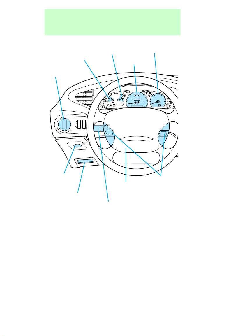
Instrumentation
Fuel gauge
(pg. 12)
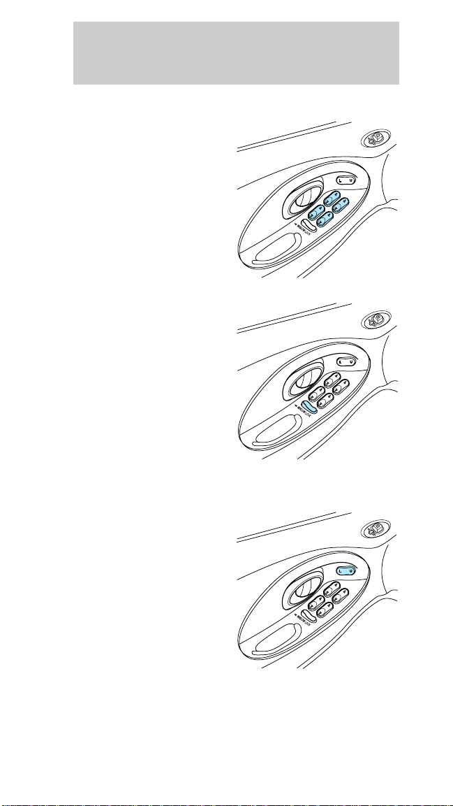
Headlamp control
(pg. 13)
Remote
trunk release*
(pg. 34)
Parking brake
release
(pg. 82)
Engine coolant
temperature gauge
(pg. 11)
Speedometer
Tachometer
(pg. 11)
(pg. 10)
Cruise
Driver
air bag
control*
(pg. 22)
(pg. 60)
Turn signal/wiper
washer control
(pg. 25)
4
Page 5
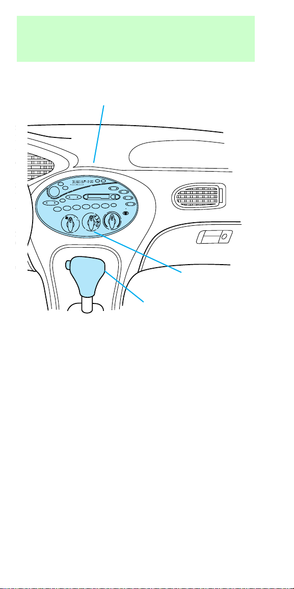
Instrumentation
Electronic sound system;
refer to Audio Guide
(pg. 21)
ST
FM 12
AMC
AM
BL RF
FM
VOL
PUSH-ON
SEEK
SCAN
TUNE
2
1
LO
MH
w
BASS
EJECT
4
3
OFF
VENT
A/C
MAX
A/C
HI
TREB
REW
FF
BAL
FADE
TAPE SIDE
TAPE
w
6
5
R-DEF
Climate
control
(pg. 14)
Gearshift
(floor-mounted shown)
(pg. 83)
* if equipped
5
Page 6
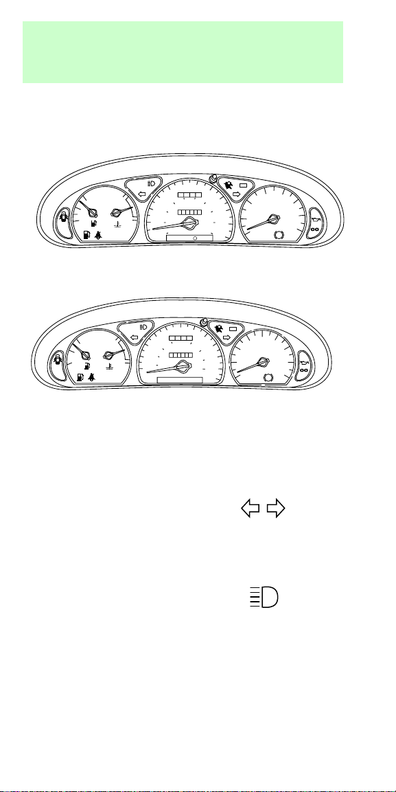
Instrumentation
WARNING LIGHTS AND GAUGES
Standard instrument cluster
50 60
40
122
20
10
0
30
60
40
20
0
MPH km/h
P R N D D 1
0
0
80
00013
100
H
F
FUEL DOOR>
E
SERVICE
ENGINE
SOON
C
LOW
THEFT
COOLANT
Optional instrument cluster
60
70
50
000
0
H
FUEL DOOR>
F
E
SERVICE
ENGINE
SOON
LOW
THEFT
COOLANT
40
100
30
60
0
00000
20
C
20
10
MPH km/h
P R N D 2 1
Turn signal
Illuminates when the
left or right turn signal
or the hazard lights are
turned on.
High beams
Illuminates when the
headlamp high beams
are on.
+–
70
80
120
90
140
160
100
180
110
80
90
140
100
110
180
120
34
5
2
RPMx1000
UNLEADED FUEL ONLY
OFF
6
7
P!
BRAKE
CRUISE
ABS
6
7
P!
BRAKE
8
CRUISE
ABS
1
0
O/D
+–
345
2
RPMx1000
1
PREMIUM UNLEADED
FUEL RECOMMENDED
0
O/D
OFF
6
Page 7

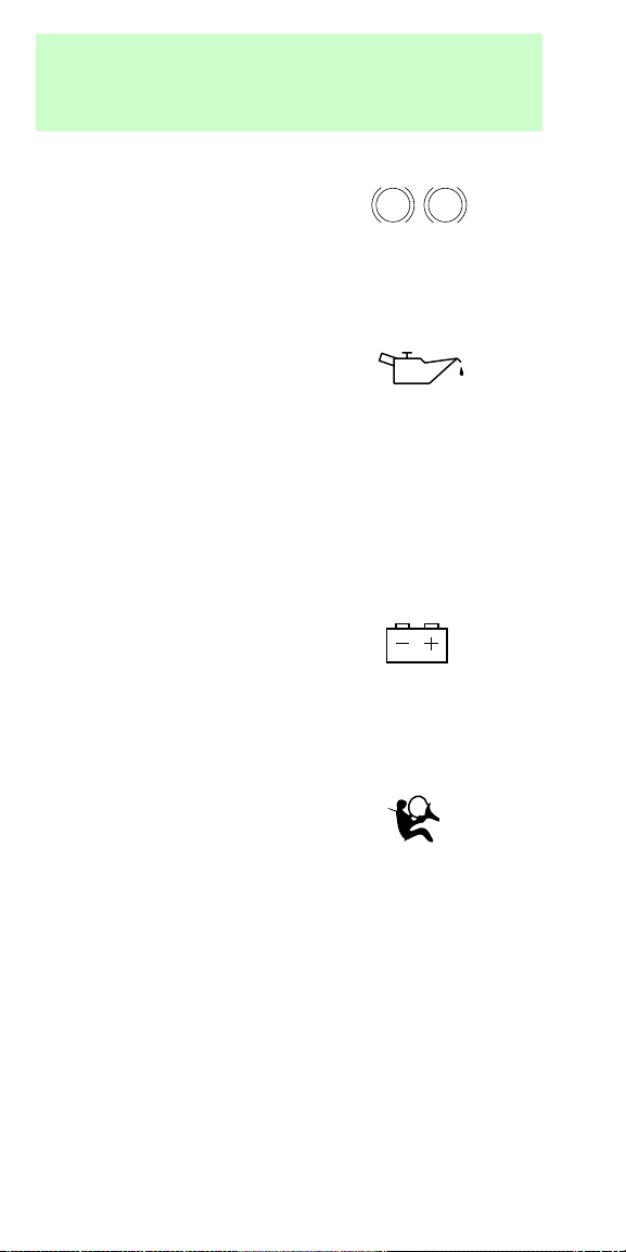
Instrumentation
Safety belt
Illuminates when the
ignition is switched on
to remind you to fasten
your safety belts. For
more information, refer to Using the safety
restraints properly in the Seating and safety
restraints chapter.
Door ajar
Illuminates when the
ignition switch is in the
ON or START position
and any door is open.
Service engine soon
This light illuminates
when the engine’s
Emission Control
System requires
service. It will also
illuminate when the ignition key is in the ON
position and the engine is off.
Low fuel
If the fuel gauge
reaches approximately
1/16th of a tank, this
lamp will illuminate.
The ignition must be turned on for this lamp to
illuminate.
SERVICE
ENGINE
SOON
Low coolant (if equipped)
This lamp will
illuminate when the
engine coolant inside
the reservoir is low.
This lamp will come on
when the ignition is first turned on, but then should
turn off. If the lamp stays on and a chime sounds,
LOW
COOLANT
7
Page 8

Instrumentation
you should check the coolant level inside the
reservoir. For instructions on adding coolant, see
Engine coolant in the index.
Anti-theft alarm light (if equipped)
This light is used when
you set the anti-theft
alarm system. See
Anti-theft system in
the index.
O/D off (if equipped)
Illuminates when the
transaxle control
switch (TCS) has been
pushed. When the light
is on, the transaxle does not shift into overdrive. If
the light does not come on when the TCS is
depressed or if the light flashes when you are
driving, have your vehicle serviced.
Anti-lock brake system (ABS) (if equipped)
Momentarily illuminates
when the ignition is
turned on and the
engine is off. If the
light stays on or continues to flash, the ABS needs
to be serviced.
THEFT
O/D
OFF
ABS
Cruise control (if equipped)
This light comes on
when the cruise control
ON button is pressed.
It turns off when the
cruise control OFF
button is pressed or when the ignition is turned to
the OFF position.
8
CRUISE
Page 9
Instrumentation
Brake system warning
Extinguishes when the
parking brake is
released. Illumination
after releasing the
parking brake indicates low brake fluid level.
Engine oil pressure
When the oil pressure
is below the normal
operating range, this
lamp will illuminate.
The engine oil level being too high or too low could
cause this lamp to illuminate. This lamp will come
on when the ignition is first turned on but then
should turn off. If the lamp stays on, continued
operation will cause severe engine damage.
Charging system
Briefly illuminates
when the ignition is
turned on and the
engine is off. The light
also illuminates when the battery is not charging
properly, requiring electrical system service.
BRAKE
P!
Air bag readiness
Briefly illuminates
when the ignition is
turned on and the
engine is off. If the
light fails to illuminate, continue to flash or remains
on, have the system serviced immediately.
Headlamps on warning chime
Sounds when the headlamps are on, the ignition is
off (and the key is not in the ignition) and the
driver’s door is opened.
9
Page 10
Instrumentation
Key-in-ignition warning chime
Sounds when the key is left in the ignition in the
OFF/LOCK or ACC position and the driver’s door is
opened.
Low coolant chime
Sounds when the engine coolant in the coolant
reservoir is low.
Safety belt warning chime
For information on the safety belt warning chime,
refer to the Seating and safety restraints chapter.
Supplemental restraint system (SRS) warning
chime
For information on the SRS warning chime, refer to
the Seating and safety restraints chapter.
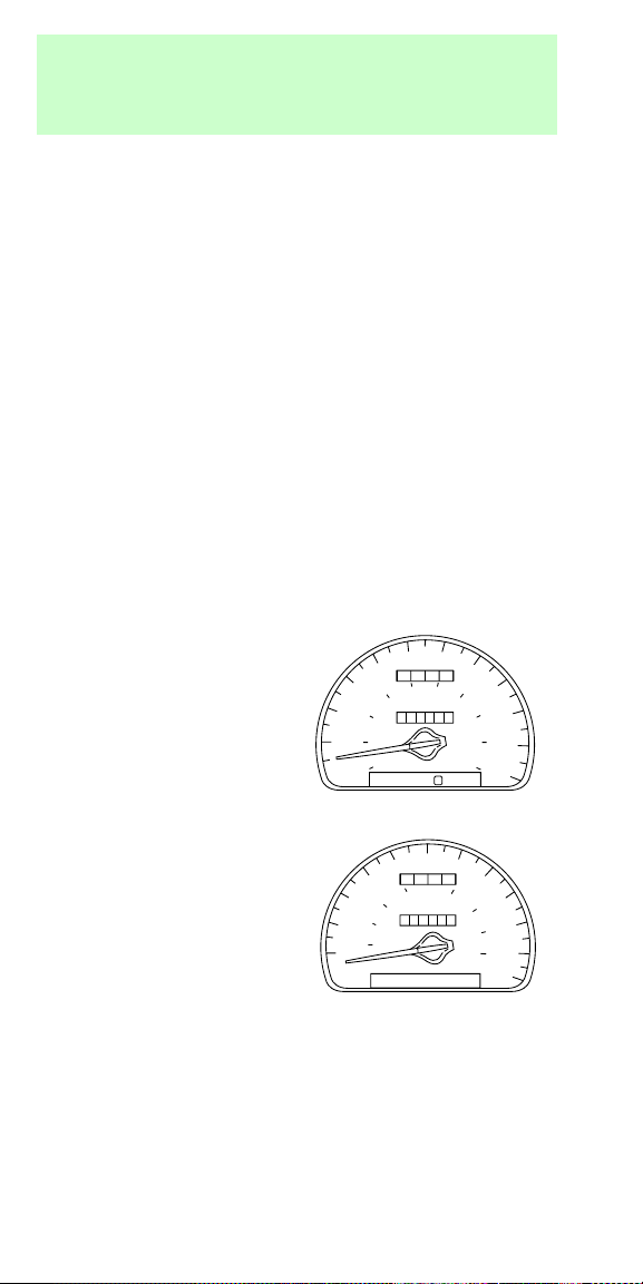
Speedometer
Indicates the current
vehicle speed.
10
30
20
0
50 60
40
000
0
100
80
60
0
00000
40
20
0
MPH km/h
P R N D D 1
70
80
120
90
140
160
100
180
110
10
30
20
10
60
50
000
0
40
100
60
0
00000
20
MPH km/h
P R N D 2 1
70
80
90
140
100
110
180
120
Page 11
Instrumentation
Tachometer
Indicates the engine
speed in revolutions
per minute.
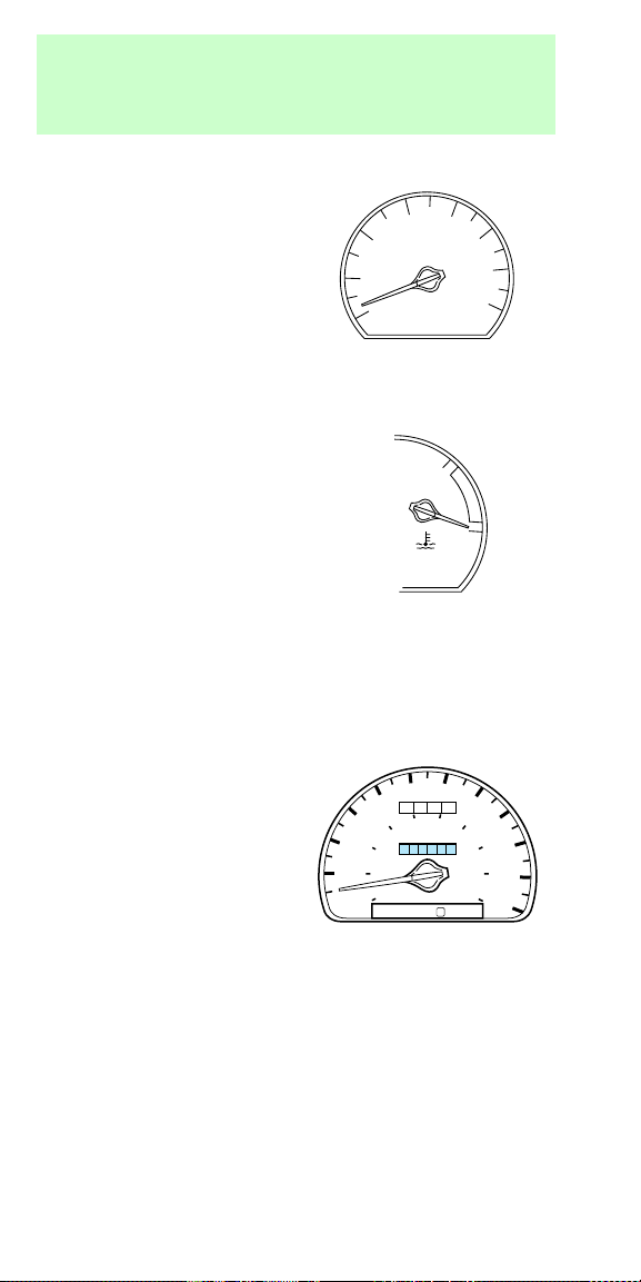
Engine coolant temperature gauge
Indicates the
temperature of the
engine coolant. At
normal operating
temperature, the
needle remains within
the normal area. If it
enters the red section,
the engine is
overheating. Switch off the ignition and let it cool.
Refer to Checking and adding engine coolant in
the Maintenance and care chapter.
Odometer
Registers the total
kilometers (mileage) of
the vehicle.
20
10
1
0
30
20
0
34
2
RPMx1000
UNLEADED FUEL ONLY
50 60
40
000
0
100
80
60
0
00000
40
0
MPH km/h
P R N D D 1
5
6
7
H
C
70
80
120
90
140
160
100
180
110
11
Page 12
Instrumentation
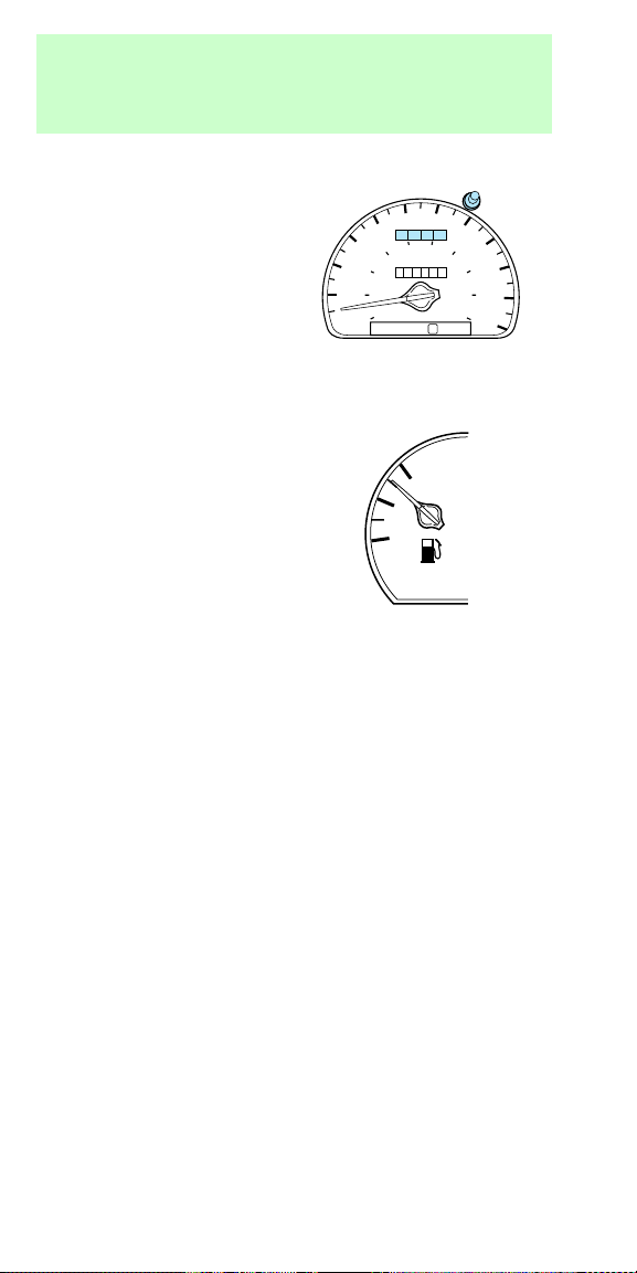
Trip odometer
Can register the
kilometers (mileage) of
individual journeys. To
reset, depress the
control.
Fuel gauge
Displays approximately
how much fuel is in
the fuel tank (when
the key is in the ON
position). The fuel
gauge may vary slightly
when the vehicle is in
motion. The ignition
should be in the OFF
position while the vehicle is being refueled.
20
10
0
40
30
60
40
20
0
MPH km/h
P R N D 1
E
50 60
122
0
80
0
00013
F
100
D
70
80
120
90
140
160
100
180
110
12
Page 13
Controls and features
TURNING ON THE INTERIOR AND EXTERIOR
LAMPS
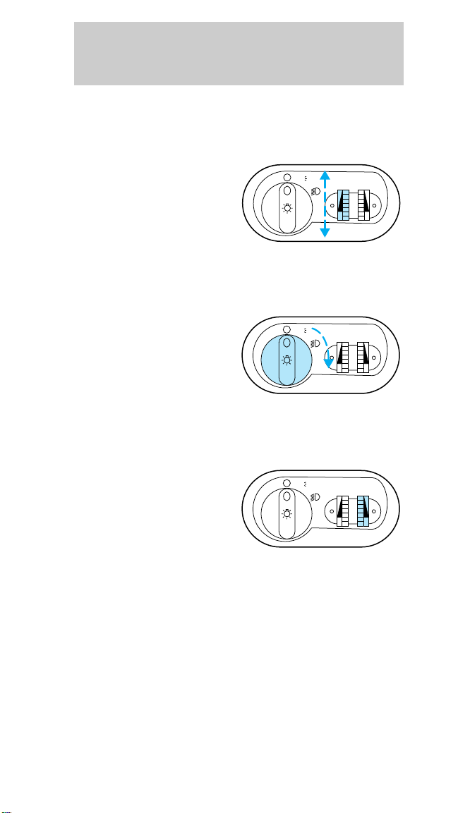
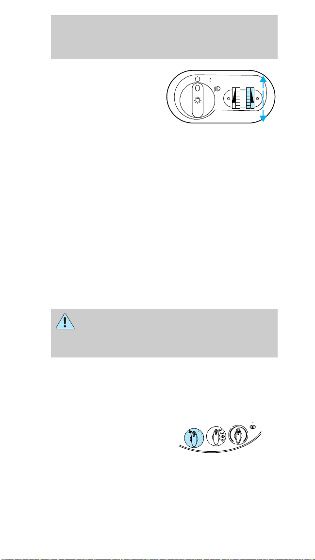
Panel dimmer control
Instrument panel
illumination, interior
lamps and cargo lamp
brightness can be
adjusted with this
control. Move the
thumbwheel up to brighten the lamps or down to
dim the lamps.
Headlamp control
Turn the headlamp
control one turn to
turn on the parking
lamps. Turn it all the
way to turn on the
headlamps.
Autolamp delay system (if equipped)
The autolamp system
sets the headlamps to
turn on and off
automatically. You can
use the autolamps to:
• Turn on the lamps
automatically at
night.
• Turn off the lamps automatically in daylight.
• Keep the lamps on for up to three minutes after
the ignition is turned off.
Setting autolamp
1. Make sure headlamp control is in the OFF
position, then turn the key to ON or start the
vehicle.
PANEL
DIM
PANEL
DIM
PANEL
DIM
AUTO
LAMP
AUTO
LAMP
AUTO
LAMP
P
P
P
13
Page 14
Controls and features
2. Locate autolamp
thumbwheel and turn
PANEL
DIM
AUTO
LAMP
P
thumbwheel to
beginning of MAX
position. The indicator
light will come on if it
is dark enough to
activate the light sensor. The closer the thumbwheel
is to the MAX mark, the longer the lamps will stay
on after leaving the vehicle.
The autolamps will now automatically turn the
headlamps on and off for you. To turn the autolamps
off, move thumbwheel back to the OFF position.
Daytime running lights (Canadian vehicles only)
The daytime running light system turns the
headlamps on, with a reduced light output, when:
• the engine is running
• the parking brake is released
• the headlamp system is in the OFF position.
The Daytime Running Light (DRL) system
will not illuminate the tail lamps and parking
lamps. Turn on your headlamps at dusk. Failure to
do so may result in a collision.
CLIMATE CONTROL SYSTEM
Manual heating and air conditioning system
Fan speed control
Controls the volume of
air circulated in the
OFF
LO
VENT
A/C
MAX
A/C
HI
vehicle.
14
R-DEF
Page 15
Controls and features
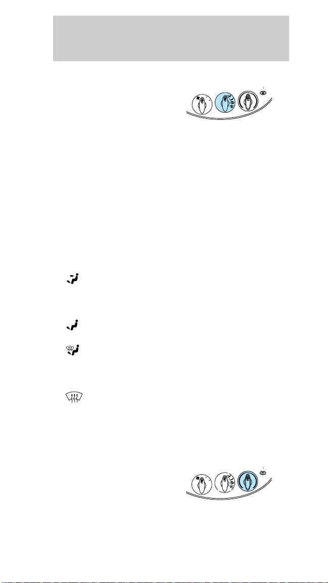
Mode selector control
Controls the direction
of the airflow to the
OFF
LO
VENT
A/C
MAX
A/C
HI
inside of the vehicle.
• MAX A/C - Uses recirculated air to cool the
vehicle. It allows for faster cooling but is noisier
than A/C. The air conditioning compressor will
operate in this mode.
• A/C - Uses outside air to cool the vehicle. It is
quieter than MAX A/C but not as economical. The
air conditioning compressor will operate in this
mode.
• VENT - Distributes outside air through the
instrument panel registers.
• OFF - Outside air is shut out and the fan will not
operate.
•
(Panel and floor) - Distributes outside air
through the instrument panel registers and the
front and rear floor ducts. The air conditioning
compressor will operate in this mode.
•
(Floor) - Allows for maximum heating. The
airflow is from the front and rear floor ducts.
• (Floor and defrost) - Distributes outside air
through the floor ducts and the windshield
defroster ducts. The air conditioning compressor
will operate in this mode.
•
(Front defrost) - Distributes outside air
through the windshield defroster ducts. It can be
used to clear ice or fog from the windshield. The
air conditioning compressor will operate in this
mode.
Temperature control knob
Turn the dial to the
desired mix of warm
OFF
LO
VENT
A/C
MAX
A/C
HI
(red) and cool (blue)
air.
R-DEF
R-DEF
15
Page 16
Controls and features
Operating tips
• In humid weather, select before driving. This
will prevent your windshield from fogging. After a
few minutes, select any desired position.
• To prevent humidity buildup inside the vehicle,
don’t drive with the climate control system in the
OFF position.
• Don’t put objects under the front seat that will
interfere with the airflow to the back seats.
• Remove any snow, ice or leaves from the air
intake area (at the bottom of the windshield
under the hood) on the passenger side of your
vehicle.
• If the air conditioner works well in MAX A/C but
not in A/C, this may indicate that the passenger
compartment air filter (if equipped) needs to be
replaced.
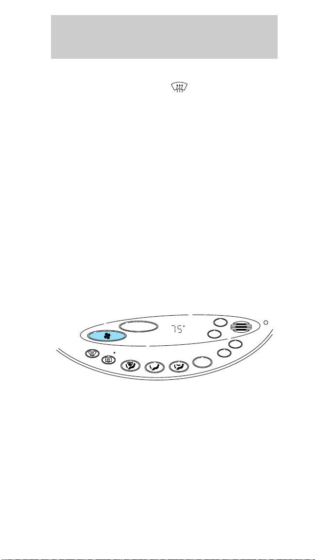
Electronic Automatic Temperature Control
(EATC) system (if equipped)
VENT
OFF
MAX
AUTO
A/C
TEMP
OUT
SIDE
—+
F-DEF
R-DEF
—+
TEMP
AUTO
F
The EATC system will maintain a selected
temperature and automatically control airflow. You
can override automatic operation with any of the six
override controls at the bottom of the control panel.
16
Page 17
Controls and features
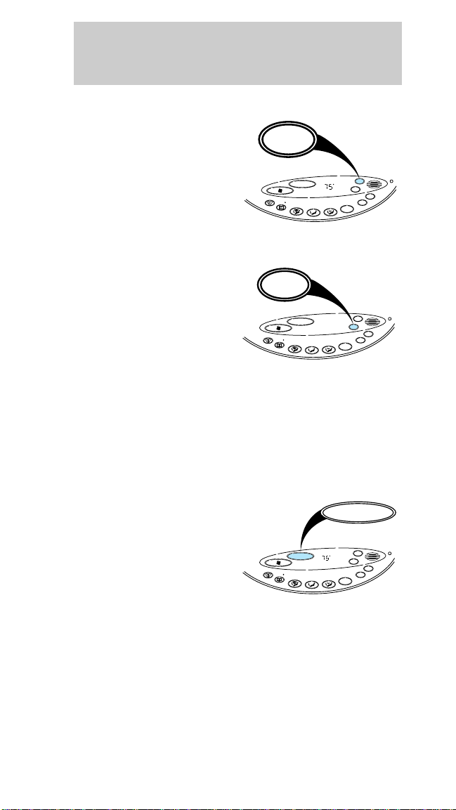
To turn on the EATC
Press AUTO or any of
the six manual override
buttons along the
bottom of the control.
The control will
operate only when the
ignition is turned to the
ON position.
To turn off the EATC
Press OFF. When the
system is off, the
display window will be
blank (dark).
Automatic operation
Press AUTO and select the desired temperature.
The system will automatically determine fan speed
and airflow location. Fan speed remains automatic
unless you press FAN. The selected temperature will
be shown on the display.
Temperature selection
TEMP will increase or
decrease the set
temperature. Pressing
TEMP will change the
temperature one
degree in either
direction. Pressing and
holding TEMP will
rapidly change the temperature (in one degree
increments) in either direction until either 18°C
(65°F) or 29°C (85°F). The temperature will then
jump –15°C (5°F) and stop at either 16°C (60°F)
which is maximum cooling or 32°C (90°F) which is
maximum heating.
AUTO
—+
F-DEF
R-DEF
OFF
—+
—+
F-DEF
R-DEF
—+
—+
F-DEF
R-DEF
—+
TEMP
TEMP
TEMP
AUTO
F
VENT
MAX
VENT
—
TEMP
AUTO
F
OFF
MAX
VENT
AUTO
OFF
TEMP
MAX
A/C
AUTO
OFF
TEMP
A/C
AUTO
TEMP
A/C
OUT
SIDE
OUT
SIDE
+
OUT
SIDE
17
Page 18

Controls and features
Changing modes (Temperature conversion)
Press MAX A/C and
the
F-DEF button
at the same time to
switch between
Fahrenheit and Celsius.
If the battery is
—+
F-DEF
R-DEF
disconnected, the
display will revert to
Fahrenheit.
(fan speed)
Once AUTO is pressed, fan speed is adjusted
automatically for existing conditions.
You can override
automatic fan speed (at
any time) by pressing
FAN. The display
window will show FAN
and a series of dots
—+
F-DEF
R-DEF
indicating fan speed. To
return to automatic fan
control, press AUTO.
Manual override controls
—+
TEMP
—+
TEMP
AUTO
AUTO
A/C
AUTO
F
OFF
MAX
A/C
VENT
—+
AUTO
F
OFF
MAX
VENT
OUT
SIDE
TEMP
OUT
SIDE
TEMP
A/C
VENT
OFF
MAX
AUTO
A/C
TEMP
OUT
SIDE
—+
F-DEF
R-DEF
—+
TEMP
AUTO
F
The override controls are located on the bottom of
the EATC and allow you to determine where airflow
is directed. To return to full automatic control, press
AUTO.
• MAX A/C - Uses recirculated air to cool the
vehicle. The temperature will display 16°C
18
Page 19

Controls and features
(60°F).To exit, press AUTO or any of the other
override controls. MAX A/C is noisier but more
economical than A/C. The airflow will be from the
instrument panel registers. The air conditioning
compressor will operate in this mode.
• VENT - Distributes outside air through the
instrument panel registers. However, the air will
not be cooled below the outside temperature.
•
•
• (Floor and defrost) - Distributes outside air
•
• OFF - Outside air is shut out and the fan will not
Displaying outside temperature
• OUTSIDE TEMP - Outside air temperature will be
(Panel and floor) - Distributes outside air
through the instrument panel registers and the
front and rear seat floor ducts. The air will be
heated or cooled based on temperature selection.
The air conditioning compressor will operate in
this mode.
(Floor) - Allows for maximum heating
through the front and rear seat floor ducts.
through the floor ducts and the windshield
defroster ducts. If the outside temperature is
about 10°C (50°F) or higher, the air conditioner
will dehumidify the air to prevent fogging. The air
conditioning compressor will operate in this mode.
F-DEF (Defrost) - Distributes outside air
through the windshield defroster ducts. It can be
used to clear ice or fog from the windshield. If the
outside temperature is about 10°C (50°F) or
higher, the air conditioner will dehumidify the air
to prevent fogging. The air conditioning
compressor will operate in this mode.
operate.
displayed. If the EATC is off, the display will go
blank after four seconds. If the EATC is on, the
display will show the outside temperature until
the button is pressed again.
19
Page 20

Controls and features
The outside temperature reading is most accurate
when the vehicle is moving. Higher readings may be
obtained when the vehicle is not moving. The
readings that you get may not agree with
temperatures given on the radio due to differences
in vehicle and station locations.
Operating tips
• In humid weather, select F-DEF before
driving. This will prevent your windshield from
fogging. After a few minutes, select any desired
position.
• To prevent humidity buildup inside the vehicle,
don’t drive with the climate control system in the
OFF position.
• Don’t put objects under the front seat that will
interfere with the air circulation to the back seats.
• Remove any snow, ice or leaves from the air
intake area (at the bottom of the windshield
under the hood) on the passenger side of your
vehicle.
• If the air conditioner works well in MAX A/C but
not in A/C, this may indicate that the passenger
compartment air filter (if equipped) needs to be
replaced.
Rear window defroster and heated outside rear
view mirrors
The defroster clears
away fog, frost and
thin ice from the rear
window and outside
rear view mirrors.
Clear away snow from rear window and mirrors. The
defroster operates for 10 minutes then shuts off. If
more defrosting is required, press the control again.
20
R-DEF
Page 21
Controls and features
Liftgate wiper and washer (wagon only)
The liftgate
wiper/washer control is
located under the
headlamp controls.
Press the wiper control
to activate the rear
wiper. Press control
again to turn off the
wiper.
Press the washer
control to activate rear
washer. The wiper will
come on when the
washer control is
pressed, if not already
on.
AUDIO SYSTEM
Refer to the Audio Guide for instructions on how to
operate the audio system.
FUEL PUMP SHUT-OFF SWITCH
Refer to the Roadside emergencies chapter for
instructions on how to operate the fuel pump
shut-off switch.
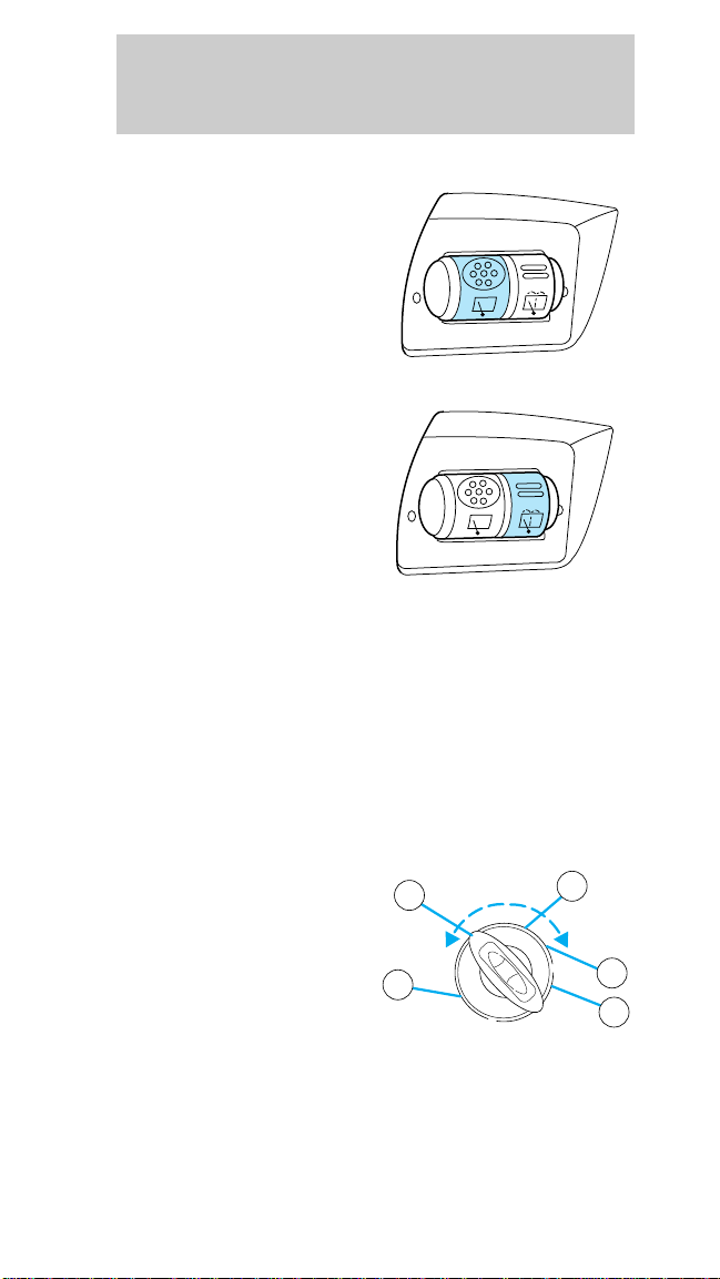
POSITIONS OF THE IGNITION
1. ACCESSORY allows
the electrical
2
3
accessories such as the
radio and
wipers/washer to
operate while the
1
engine is not running.
2. LOCK locks the
steering wheel and gearshift lever and allows key
removal.
4
5
21
Page 22
Controls and features
3. OFF shuts off the ignition and accessories and
allows the gearshift and steering wheel to move.
4. ON tests the warning lights. The key must remain
here when the engine is running.
5. START cranks the engine. The key must return to
ON when running.
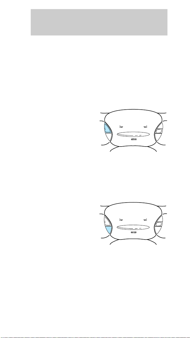
CRUISE CONTROL
To turn cruise control on
Press ON.
Vehicle speed cannot
be controlled until the
vehicle is travelling at
or above 48 km/h (30
mph).
Do not use the cruise control in heavy traffic or
winding, slippery or unpaved roads.
Do not shift into N (Neutral) while the cruise
control is on.
To turn cruise control off
Press OFF or turn off
the vehicle ignition.
ON
OFF
ON
OFF
RESUME
SET
ACCEL
COAST
RESUME
SET
ACCEL
COAST
Once cruise control is switched off, the previously
programmed set speed will be erased.
22
Page 23
Controls and features
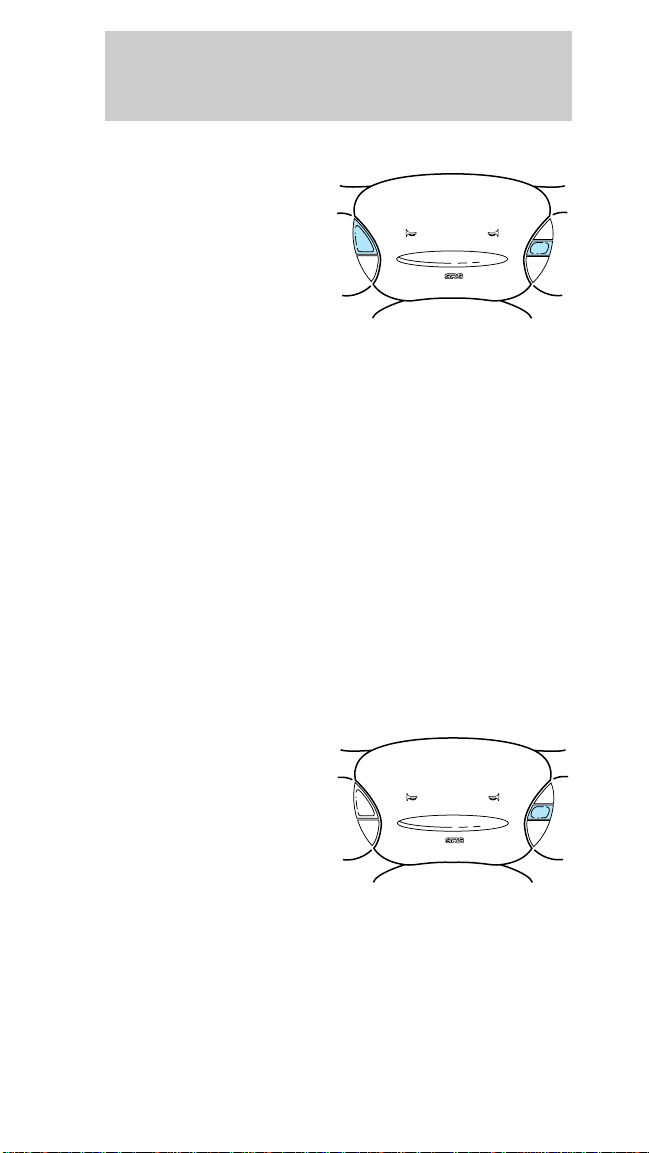
To set a speed
Press SET ACCEL. For
cruise control to
operate, the cruise
control must be ON
and the vehicle speed
must be greater than
48 km/h (30 mph).
If you drive up or down a steep hill, your vehicle
speed may vary momentarily slower or faster than
the set speed. This is normal.
Cruise control cannot reduce the vehicle speed if it
increases above the set speed on a downhill. If your
vehicle speed is faster than the set speed while
driving on a downhill in Overdrive, you may want to
shift to the next lower gear to reduce your vehicle
speed.
If your vehicle slows down more than 16 km/h (10
mph) below your set speed on an uphill, your cruise
control will disengage. This is normal. Pressing
RESUME will re-engage it.
Do not use your cruise control in heavy traffic or
roads that are winding, slippery or unpaved.
ON
OFF
RESUME
SET
ACCEL
COAST
To set a higher set speed
• Press and hold SET
ACCEL. Release the
control when the
desired vehicle
speed is reached or
ON
OFF
RESUME
SET
ACCEL
COAST
• Press and release
SET ACCEL. Each
press will increase
the set speed by 1.6 km/h (1 mph) or
• Accelerate with your accelerator pedal, then press
and release SET ACCEL.
23
Page 24
Controls and features
You can accelerate with the accelerator pedal at any
time during cruise control usage. Releasing the
accelerator pedal will return your vehicle to the
previously programmed set speed.
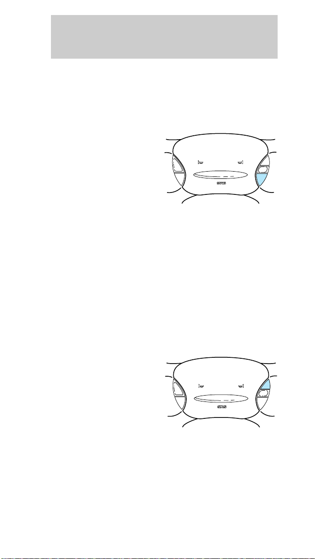
To set a lower set speed
• Press and hold
COAST. Release the
control when the
desired speed is
reached or
• Press and release
COAST. Each press
will decrease the set
speed by 1.6 km/h (1 mph) or
• Depress the brake pedal. When the desired
vehicle speed is reached, press SET ACCEL.
To disengage cruise control
• Depress the brake pedal.
Disengaging the cruise control will not erase the
previously programmed set speed.
Pressing OFF will erase the previously programmed
set speed.
ON
OFF
RESUME
SET
ACCEL
COAST
To return to a set speed
• Press RESUME. For
RESUME to operate,
the vehicle speed
must be faster than
48 km/h (30 mph).
24
ON
OFF
RESUME
SET
ACCEL
COAST
Page 25
Controls and features
Indicator light
Lights when the cruise
control is turned on
and remains lit until
either the cruise
control or the ignition
is turned off.
TURN SIGNAL CONTROL
Turn signals
Push the control down
to activate the left turn
signal. Push control up
to activate the right
turn signal.
High beams
Push the control
forward to activate the
high beams.
CRUISE
25
Page 26
Controls and features
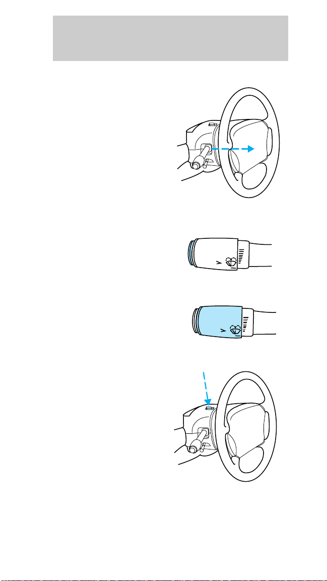
Flash-to-pass
Pull the control toward
you to activate the
flash-to-pass function.
WINDSHIELD WIPERS AND WASHER
Push the control on
the end of the turn
signal control to
activate washer. Push
the control once for a single wipe. Push and hold for
a longer wash cycle.
Turn the dial at end of
the turn signal control
to adjust wiper interval
and speed.
HI
LO
F
S
OFF
HI
LO
F
S
OFF
HAZARD FLASHER
Push the control
located on top of the
steering column to
activate four-way
flashers. Push control
again to turn flashers
off.
26
Page 27
Controls and features
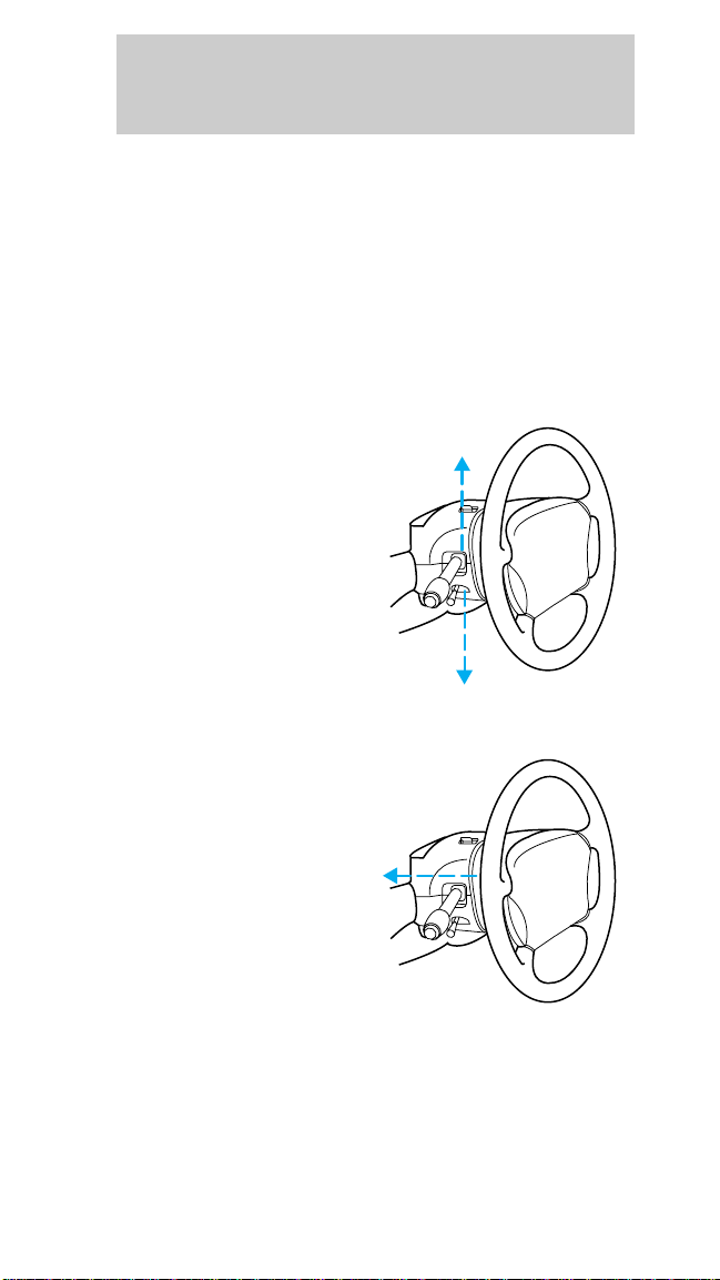
TILT STEERING
Pull the tilt steering
control toward you to
move the steering
wheel up or down.
Hold the control while
adjusting the wheel to
the desired position,
then release the
control.
Never adjust the steering wheel when the
vehicle is moving.
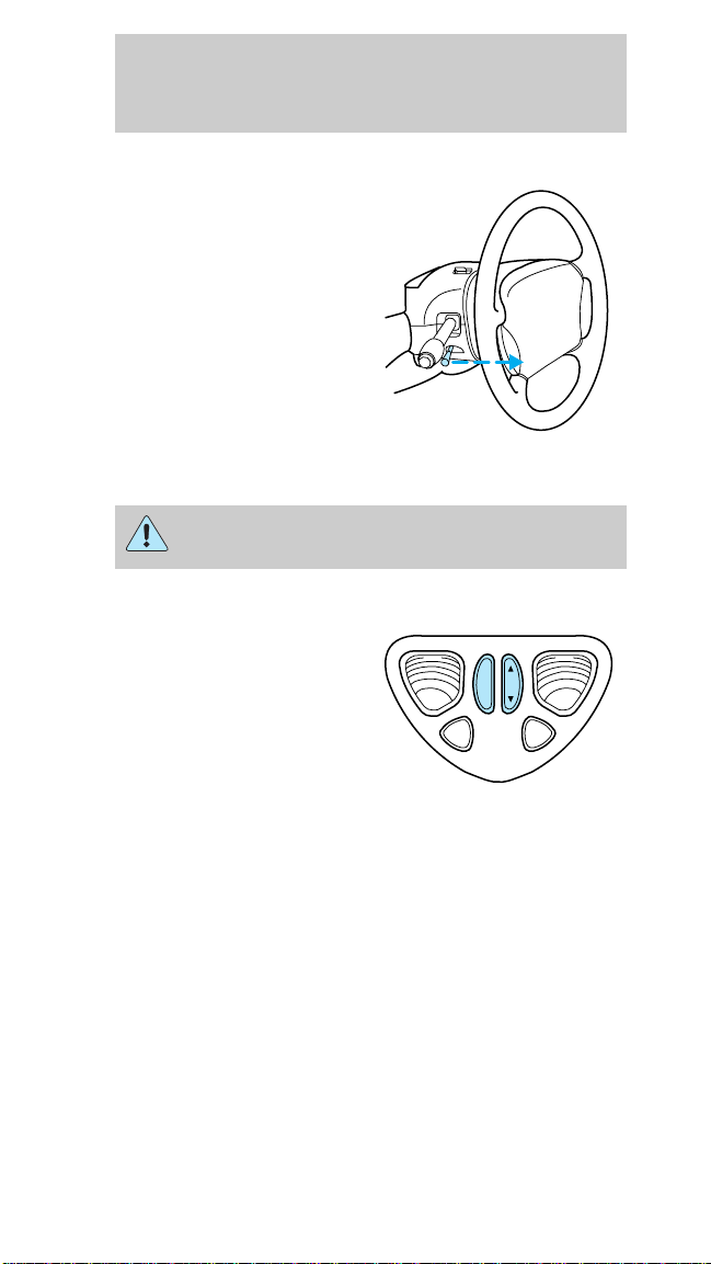
MOON ROOF (IF EQUIPPED)
Press SLIDE to open
and close moon roof.
Press AUTO and
release to open
completely with one
touch.
Press UP or DN on the
TILT control to tilt
moon roof when closed.
LIGHT
SLIDE
TILT
UP
AUTO
DN
LIGHT
Sliding shade
The moon roof has a sliding shade that you can
open or close when the moon roof is closed.
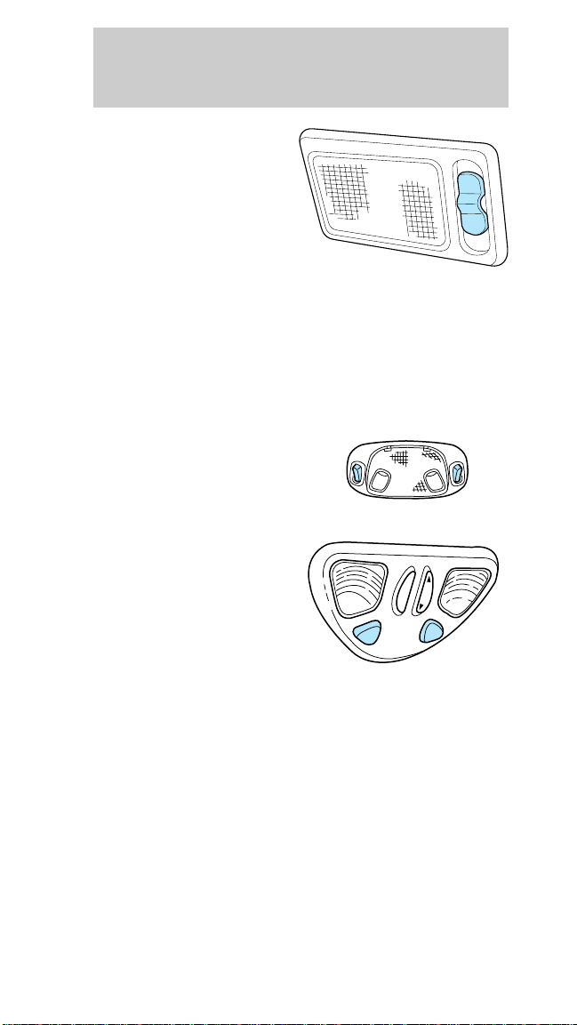
DOME LAMPS AND MAP LAMPS
The front dome lamp is located overhead between
the driver and passenger seats. If the vehicle is
equipped with a moon roof, the dome lamp is
located behind the moon roof.
27
Page 28
Controls and features
The dome lamp will
stay on if the control is
moved to the ON
position. When the
control is in the DOOR
position, the lamp will
only come on when a
door is opened. If the
control is moved to the
OFF position, the lamp will not come on at all.
The dome lamp will illuminate whenever a front
door is opened. If either front door has been opened
from the outside, the lamp will remain on for 25
seconds after the door is shut. If any other door has
been opened from the inside, the lamp will shut off
immediately after the door is closed.
The map lamps and
controls are located on
the dome lamp. Press
the controls on either
side of each map lamp to activate the lamps.
If equipped with a
moon roof, the map
lamps are located on
the moon roof control
panel. Press LIGHT to
LIGHT
illuminate the map
lamp.
TILT
OFF DOOR ON
SLIDE
LIGHT
28
Page 29
Controls and features
POWER WINDOWS
Press and hold the
rocker switches to
open and close
windows. When AUTO
is pressed and released
quickly, the driver’s
window will open
completely without
holding the switch
down. Each passenger
has window controls.
The window lock
feature allows only the
driver to operate the
power windows.
POWER DOOR LOCKS (IF EQUIPPED)
Press U to unlock all
doors and L to lock all
doors.
29
Page 30
Controls and features
Central locking/Two step unlocking
When unlocking the driver or front passenger door
with the key, turn it once toward the front of the
vehicle to unlock that door only. Turn the key a
second time to unlock all doors. When locking, turn
the key toward the back of the vehicle to lock all
doors.
Liftgate (wagon only)
The power liftgate lock
is located on the right
inside trim panel in the
cargo area. When this
lock is pressed, all
doors and the liftgate
will lock.
POWER SIDE VIEW MIRRORS
To change mirror
position, first select a
mirror by moving the
selector control left
) or right ( ),
(
then moving the
control to set the
desired position.
Power heated side view mirrors (if equipped)
The heated mirrors will melt frost, thin ice or
remove fog when the rear window defroster is
activated.
30
Page 31

Controls and features
CHILDPROOF DOOR LOCKS
When these locks are set, the rear doors cannot be
opened from the inside. The rear doors can be
opened from the outside when the doors are
unlocked.
Move lock control up
to engage the lock.
Move control down to
disengage childproof
locks.
CONSOLE
If your vehicle is
equipped with a floor
mounted gearshift, it
will have a full console
with the following
features:
• cup holders (push to
open)
31
Page 32

Controls and features
• coin holder and
utility bin
• cassette/CD storage
• cellular phone (if
equipped)
• ashtray (push to
open)
The release for the utility compartment is on the
front of the console, just below the armrest. Press
and release at the ridges to open.
32
Page 33

Controls and features
If your vehicle is
equipped with a
cellular phone, press
the latch release
located on the driver’s
side edge of the
console lid to access
the phone.
If your vehicle is
equipped with the
column shift, it has a
center console in the
center front seating
position.
The center console has the same features as the full
console. To open the storage compartment, raise the
armrest and pull the strap on the seat up and
toward the front of the vehicle. The cupholders in
the center console can be removed for cleaning.
Cellular phone
Refer to the cellular phone user’s manual for
instruction on operation.
POSITIVE RETENTION FLOOR MAT (IF
EQUIPPED)
Position the floor mat so that the eyelet is over the
pointed end of the retention post and rotate forward
to lock in. Make sure the mat does not interfere with
the operation of the accelerator and brake pedal. To
remove the floor mat, reverse the installation
procedure.
33
Page 34

Controls and features
OPENING THE TRUNK WITH REMOTE
CONTROL (IF EQUIPPED)
Press the remote
release control on the
instrument panel to the
left of the steering
wheel.
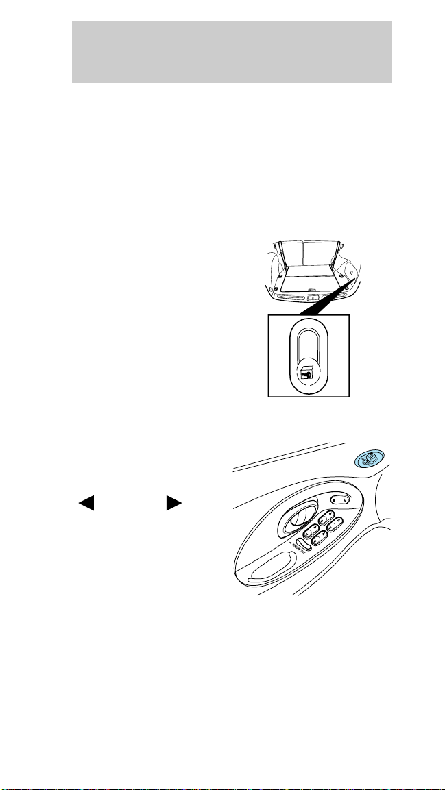
LIFTGATE (WAGON ONLY)
You can open the
entire liftgate or just
the liftgate window. To
open the entire liftgate,
press the release
button hidden under
the exterior trim panel
just above the license
plate.
You must lock the liftgate with the key or power
lock control; it does not lock automatically.
The window locks when the liftgate is locked. To
open the window, make sure the liftgate and window
are unlocked, then press the outside lock cylinder.
The window can only be opened from the outside.
To prevent any damage to the liftgate and window,
close them completely before driving.
34
Page 35

Controls and features
STORAGE COMPARTMENT (WAGON ONLY)
Your vehicle comes
equipped with a
storage compartment
in the floor of the
cargo area. An
additional
compartment is in the
rear trim panel on the
right. Always put the
load you are carrying as far forward as possible.
CARGO NET (IF EQUIPPED)
The cargo net secures
lightweight objects in
the cargo area. Attach
the net to the anchors
provided. Do not put
more than 22 kg (50
lbs.) in the net. This
net is not designed to
restrain objects during
a collision.
CARGO COVER (WAGON - IF EQUIPPED)
You can cover the rear
compartment by
fastening the cover
into the pockets in the
trim panel (make sure
the cover is right side
up so it unrolls from
the top), then pulling
and hooking the cover
into the pockets into the trim panel.
REWINDING THE SLIDING SHADE
If the shade is damaged or loses its spring tension
from excessive use, manual rewinding of the shade
may be necessary. The following procedure is a
two-person operation:
35
Page 36

Controls and features
1. Remove the shade from the mounting brackets by
detaching the safety clip and pressure fit plastic
knobs from either side of the shade.
2.Wrap the vinyl around the tube twice by twisting
the tube away from you. Tuck the edged of the vinyl
end cap with each wrap.
3. Fold the vinyl toward the center, making sure the
edges clear the end cap slots. Use tape or a rubber
band to hold the vinyl on the left side of the tube..
4. Push in the right end cap (marked R) about 6 mm
(1/4 inch) to disengage the clutch and hold in while
turning the tube toward you fourteen times.
5. Let go of the right end cap and unfold the vinyl.
Place the vinyl into the end cap slots.
6. Place the shade back into the vehicle.
The cover may cause injury in a sudden stop
or accident if it is not securely installed.
LUGGAGE RACK (WAGON ONLY)
The rear crossbar can be adjusted to fit the item
being carried. The front crossbar does not move. No
more than 44 kg (100 lbs.) can be loaded on the
luggage rack.
To adjust the luggage
rack, loosen the
adjusting levers by
pushing them toward
the front of the
vehicle, then slide the
crossbar forward and
lock the adjusting
levers by pulling them
toward the back of the vehicle.
36
Page 37

Controls and features
KEYLESS ENTRY SYSTEM (IF EQUIPPED)
You can lock or unlock
the vehicle doors
without using a key.
See also Remote entry system (if equipped) in this
chapter.
The computer code that operates the keyless system
is located on your owner’s wallet card found in the
glove compartment.
Illuminated entry system:
• turns on the interior lights for approximately 25
seconds and
• lights up the keypad controls for five seconds.
Do not push the control keypad with any hard object
that could damage the controls.
Programming your own entry code
This code does not replace the permanent code from
the dealership.
To program your own code:
1. Select five digits for your personal code.
2. Enter the permanent code that the dealership
gave you.
3. Within five seconds,
press 1/2.
1 234567890
1234567890
4. Within five seconds of pressing 1/2, enter your
personal code, pressing each digit within five
seconds of the previous digit.
You can now use either code. The system
remembers only one personal code at a time.
To erase your personal code:
1. Enter the original permanent code.
37
Page 38

Controls and features
2. Press 1/2 within five
seconds of step one.
3. Wait six seconds.
For maximum security, do not set a code that
presents the numbers in sequential order or uses the
same button five times.
Unlocking the doors with the keyless entry
system
The driver’s door must be unlocked before any
other. If more than five seconds pass between
pressing numbers, enter the code again. The system
has shut down if the keypad light is out. If the
keyless entry system does not work, use the key or
remote entry transmitter(s).
1. To unlock the driver’s door, enter one of the two
codes. After pressing the fifth number, the driver’s
door unlocks.
2. To unlock the
passenger’s door(s) and
liftgate (wagon), press
the 3/4 button within
five seconds of unlocking the driver’s door.
3. To unlock the trunk
or liftgate (wagon),
enter the five-digit
factory code, then
press the 5/6 button within five seconds.
1 234567890
1234567890
1234567890
Locking the doors with the keyless entry
system
To lock all the doors,
press 7/8 and 9/0 at the
same time. It is not
1234567890
necessary to first enter
the keypad code.
38
Page 39

Controls and features
Operating your perimeter anti-theft system (if
equipped) from the keyless entry pad
The keyless entry
system arms by
pressing 7/8 and 9/0.
To disarm or reset a triggered anti-theft alarm, enter
the five digit code.
All doors must be fully closed for the anti-theft
system to arm. Refer to the Anti-theft system
section, if equipped, in this chapter for more details.
Autolock
The autolock feature is part of your remote keyless
entry system which locks all of the doors when:
• all vehicle doors are closed
• the ignition key is turned to the ON position
• the brake pedal is pressed
• you shift through R (reverse)
• one second has elapsed after the brake pedal is
released.
The autolock feature repeats when:
• a door is opened and then all doors are closed
• the brake pedal is released.
The doors may not lock automatically if the driver:
• shifts through gears without pressing the brake
• shifts through gears quickly after starting the
vehicle
• releases their foot from the brake while someone
has stepped out of the vehicle for a moment.
Deactivating the system by using the controls for the
keyless entry system:
1. Enter your permanent five-digit entry code (not
the user code you may have set).
2. Within five seconds, press and hold 7/8.
1 234567890
39
Page 40

Controls and features
3. Within five more
seconds, press and
release 3/4.
4. Release 7/8.
To reactivate the system, repeat the system
deactivating instructions.
You can also deactivate or reactivate the autolock
feature by this method:
1. Make sure the anti-theft system is not armed or
triggered, ignition is off and all doors are closed.
2. Turn the ignition key from OFF to ON.
3. Press the door power unlock switch three times.
4. Turn the ignition key from ON to OFF.
5. Press the door power unlock switch three times.
6. Turn the ignition key back to ON within 30
seconds of step two.
7. The horn should chirp once. If not, wait 30
seconds and repeat steps one through six.
8. Press the door power unlock switch.
9. Press the door power lock switch.
10. The horn will chirp once if the autolock feature
was deactivated, twice (one short chirp followed by
a long chirp) if the autolock feature was activated.
11. Turn the ignition key to OFF.
12. The horn will chirp once to confirm you
activated or deactivated the autolock feature.
1 234567890
40
Page 41

Controls and features
REMOTE ENTRY SYSTEM (IF EQUIPPED)
The remote entry
system allows you to
lock or unlock all
vehicle doors without a
key.
It also arms and
disarms the anti-theft
system. (For more
information on the anti-theft system, refer to
Anti-theft system in this chapter.) The remote entry
features only operate with the ignition in the OFF
position.
Unlocking the doors
Press UNLOCK once to
unlock the driver and
illuminate the interior
lamps.
Press UNLOCK a
second time, within
five seconds, to unlock
all doors and liftgate
(wagon).
PANIC
LOCK
UN
LOCK
PANIC
TRUNK
LOCK
UN
LOCK
TRUNK
Using the trunk button
Press once to open the
trunk (sedan) or
unlock the liftgate
(wagon).
PANIC
LOCK
UN
LOCK
TRUNK
41
Page 42

Controls and features
Locking the doors
Press LOCK to lock all
doors and liftgate
(wagon).
To confirm all doors
are closed and locked,
press LOCK a second
time. The doors will
lock again, the horn
will chirp and the lamps will flash.
This process will arm your anti-theft system. For
more information on arming the anti-theft system,
refer to Anti-theft system in this chapter.
Sounding the PANIC alarm
Press PANIC to
activate the alarm.
To deactivate the
alarm, press PANIC
again or turn the
ignition to ACC or ON.
This device complies
with part 15 of the
FCC rules. Operation is subject to the following two
conditions: (1) This device may not cause harmful
interference, and (2) This device must accept any
interference received, including interference that
may cause undesired operation.
PANIC
PANIC
LOCK
UN
LOCK
TRUNK
LOCK
UN
LOCK
TRUNK
Arming and disarming the alarm system
Your remote entry system will:
• automatically arm the factory installed anti-theft
system when the doors are locked.
• reset the triggered anti-theft alarm (when the
driver’s door is unlocked or when PANIC is
pressed on a programmed remote entry
transmitter).
42
Page 43

Controls and features
Replacing the batteries
The transmitter is powered by two coin type
three-volt lithium batteries. A decrease in operating
range can be caused by:
• battery failure
• weather conditions
• structures around the vehicle
To replace the batteries:
1. Twist a thin coin between the two halves of the
transmitter. DO NOT TAKE THE FRONT PART OF
THE TRANSMITTER APART.
2. Place the positive (+) side of new batteries down.
3. Snap the two halves back together.
Replacing lost transmitters
Take all your vehicle’s transmitters to your dealer for
programming if:
• a transmitter is lost or
• you want to purchase additional transmitters (up
to four)
ILLUMINATED ENTRY SYSTEM
The interior lamps
illuminate when:
• the remote entry
system is used to
unlock the door or
sound the personal
alarm.
The system
automatically turns off after 25 seconds or when the
ignition is turned to the START or ACC position.
The inside lights will not turn off if:
• they have been turned on with the dimmer
control or
LOCK
UN
LOCK
PANIC
43
Page 44

Controls and features
• any door is open.
PERIMETER ANTI-THEFT SYSTEM (IF
EQUIPPED)
When armed, this system will protect your vehicle
from unauthorized entry. When unauthorized entry
occurs, the system will flash the headlamps, parking
lamps and the theft indicator lamp and will chirp the
horn.
Arming the system
The system is ready to arm whenever the ignition is
turned off. Any of the following actions will prearm
the alarm system:
• Pressing LOCK on
the remote
transmitter (doors
opened or closed).
• Pressing 7/8 and 9/0
on the keyless entry
pad at the same time
to lock the doors
(doors opened or closed).
• Opening a door and pressing the power door lock
button to lock the doors.
• Using the door key to lock the doors (doors
opened or closed).
If a door or the liftgate
(wagon) is open, the
system is prearmed
and is waiting for the
door to close or liftgate
to close. The THEFT indicator in the instrument
cluster will be lit continuously when the system is
prearmed.
LOCK
PANIC
1 234567890
THEFT
TRUNK
UN
LOCK
44
Page 45

Controls and features
Once the doors and
liftgate (wagon) are
THEFT
closed, the system will
arm in 30 seconds.
When the system is armed the THEFT indicator will
flash.
When you press the
LOCK button twice
within 5 seconds on
PANIC
LOCK
UN
LOCK
TRUNK
your remote entry
transmitter, the horn
will chirp once to let
you know that the
system is armed.
If the doors or liftgate (wagon) are not closed and
you press the remote entry transmitter twice to
confirm the doors are locked, the horn will chirp
twice to warn you that the system is not arming.
Disarming the system
You can disarm the system by any of the following
actions:
• Unlock the doors by
using your remote
entry transmitter.
PANIC
LOCK
UN
LOCK
TRUNK
• Unlock the doors by
using your keyless
entry pad.
1 234567890
• Unlock the doors or liftgate with a key. Turn the
key full travel (toward the front of the vehicle) to
make sure the alarm disarms.
• Turn ignition to ACC or ON.
45
Page 46

Controls and features
• Press PANIC on
remote entry
transmitter. This will
PANIC
LOCK
UN
LOCK
TRUNK
disarm the system
when alarm is
triggered or
sounding.
CODED-KEY ANTI-THEFT SYSTEM (IF
EQUIPPED)
Your vehicle is equipped with a coded-key anti-theft
system. Only the correct key will be able to start
your vehicle. If your keys are lost or stolen, you
must take your vehicle to a Ford dealership for
re-programming.
Programming additional keys
If you need additional keys electronically coded for
your vehicle, spares can be purchased (total of 16
keys). To program a new key, perform the following
procedure:
1. With the coded key in the ignition, turn the
ignition from ON to OFF.
2. Within 15 seconds of
THEFT
turning ignition off,
insert new electronic
key into the ignition
and turn it from OFF
to ON or START. If successful, the anti-theft
indicator will illuminate for two seconds. Repeat
procedure for all new keys.
If key coding fails, the
anti-theft indicator will
THEFT
flash.
Coding failure can be caused by any of the following:
• The new key was not inserted into the ignition
within 15 seconds.
46
Page 47

Controls and features
• 16 keys have already been programmed.
• The new key does not have an electronic code.
47
Page 48

Seating and safety restraints
SEATING
Head restraints
The head restraints can
be moved up and
down.
Front seats
Adjusting the manual seats
Lift bar to move seat
forward or backward.
Pull lever up to adjust
seatback.
48
Never adjust the driver’s seat or seatback
when the vehicle is moving.
Page 49

Seating and safety restraints
Adjusting the power seats (if equipped)
Press to move front or
rear of seat up and
down.
Press in the direction
to raise or lower the
seat, or to move the
seat forward or
backward.
Push to increase or
decrease lumbar
support.
Pull lever up to adjust
seatback.
Never adjust the driver’s seat or seatback
when the vehicle is moving.
49
Page 50

Seating and safety restraints
2nd seat/Split-folding rear seat
One or both rear seatbacks can be folded down to
provide additional cargo space.
To lower the
seatback(s) from inside
the vehicle, lift
seatback release
handle, pull tab, then
fold seatback down.
In the sedan, the
seatbacks can also be
folded down from
OPEN
inside the trunk. Move
the release lever on
the back of the rear
seatback to the OPEN
position and fold the
seatback down.
When raising the seatback(s), make sure you hear
the seat latch into place.
3rd seat (wagon only)
The third seat faces the rear of the vehicle. For
height and weight limits, see the label on the seat
cushion. When the seat is down, the back of your
wagon has a flat surface for carrying cargo.
To open up the seat:
OPEN
50
Page 51

Seating and safety restraints
1. Unlock the floor
panel with the key,
then use the handle to
fold the floor panel
toward the front of the
car.
2. Remove the cargo cover. The cargo cover must be
removed or the seatback will not latch in the upright
position.
3. Lift the remote latch
release on the left side
of the compartment
and fold the remaining
floor panel until it
latches. Make sure the
seatback is locked in
the upright position.
To close the seat, make sure the safety belts are in
their correct notches, then lift the remote latch
release and push the seat down until it latches. Pull
up on the handle and push the floor panel into
place.
51
Page 52

Seating and safety restraints
SAFETY RESTRAINTS
Safety restraints precautions
Always drive and ride with your seatback
upright and the lap belt snug and low across
the hips.
To prevent the risk of injury, make sure
children sit where they can be properly
restrained.
It is extremely dangerous to ride in a cargo
area, inside or outside of a vehicle. In a
collision, people riding in these areas are more
likely to be seriously injured or killed. Do not allow
people to ride in any area of your vehicle that is
not equipped with seats and safety belts. Be sure
everyone in your vehicle is in a seat and using a
safety belt properly.
Combination lap and shoulder belts
1. To fasten, insert the
tongue into the slot in
the buckle.
2. To unfasten, push
the red release button
and remove the tongue
from the buckle.
The outboard safety restraints in the vehicle are
combination lap and shoulder belts. The front and
rear seat passenger outboard safety belts have two
types of locking modes described below:
52
Page 53

Seating and safety restraints
To test the vehicle
sensitive (emergency)
locking mode, pull the
shoulder belt quickly to
lock.
The vehicle sensitive mode is the normal retractor
mode, adjusting shoulder belt tightness in response
to vehicle movement. For example, if the driver
brakes suddenly or turns a corner sharply or the
vehicle receives an impact of 8 km/h (5 mph) or
more, the combination safety belts would lock to
help reduce forward movement of the driver and
passengers.
Automatic locking mode
In this mode, the shoulder belt is locked in a certain
position by the occupant and does not adjust
tightness during vehicle movement.
The automatic locking mode is not available on the
driver belt.
When to use the automatic locking mode
• When a tight lap/shoulder fit is desired.
• Any time a child safety seat is installed in the
vehicle. Refer to Children and infant or Child
safety seats later in this chapter.
53
Page 54

Seating and safety restraints
How to use the automatic locking mode
• Buckle the
combination lap and
shoulder belt.
• Grasp the shoulder
portion and pull
downward until the
entire belt is
extracted.
• Allow the belt to retract. As the belt retracts, you
will hear a clicking sound. This indicates the
safety belt is now in the automatic locking mode.
How to cancel the automatic locking mode
Disconnect the combination lap/shoulder belt and
allow it to retract completely to cancel the automatic
locking mode and activate the vehicle sensitive
(emergency) locking mode.
Safety belts for front outboard passenger and
rear outboard seating positions (except wagon
rear-facing position)
Your vehicle is equipped with a dual locking mode
retractor on the shoulder belt portion of the
combination lap/shoulder safety belt at these
positions.
54
Page 55

Seating and safety restraints
Front safety belt height adjustment
Your vehicle has safety belt height adjustments for
the driver and front passenger. Adjust the height of
the shoulder belt so the belt rests across the middle
of your shoulder.
To lower the shoulder
belt height, push the
button and slide the
height control down.
To raise the height of
the shoulder belt, slide
the height adjuster up.
Pull down on the
height adjustment
assembly to make sure
it is locked in place.
Center rear lap belt (sedan)
The safety belt in the center rear seating position
has a detachable shoulder belt.
55
Page 56

Seating and safety restraints
To attach the shoulder
belt to the lap belt, pull
the shoulder belt out
from the retractor in
the seatback and insert
into the lap belt
connecting pin into the
wide end of the key
slot on the shoulder
belt. Pull the
connecting pin into the
narrow end of the key
slot until you hear a
snap and feel it latch.
Make sure the shoulder
belt is securely
fastened to the lap belt
by pulling up on the shoulder belt.
Lap belts
The lap belts in the center front seating position (if
equipped) and center rear seating position (wagon)
do not adjust automatically. You must adjust them to
fit snugly and low as possible around your hips. Do
not wear the lap belt around your waist.
Make sure you insert the tongue into the correct
buckle. If you need to lengthen the belt, turn the
tongue at a right angle to the belt and pull across
your lap until it reaches the buckle. If you need to
tighten the belt, pull the loose end of the belt
through the tongue until it is snugly across the hips.
Shorten and fasten the belt when not in use.
LAP BELTS
The lap belt in the center rear seating position
(wagon) does not adjust automatically. You must
adjust it to fit snugly and low as possible around
your hips. Do not wear the lap belt around your
waist.
56
Page 57

Seating and safety restraints
Make sure you insert the tongue into the correct
buckle. If you need to lengthen the belt, turn the
tongue at a right angle to the belt and pull across
your lap until it reaches the buckle. If you need to
tighten the belt, pull the loose end of the belt
through the tongue until it is snugly across the hips.
Shorten and fasten the belt when not in use.
Safety belts for rear-facing occupants (wagon
only)
Never use child safety seats in the third seat
of a wagon.
Your vehicle is equipped with safety belts containing
an adjust tongue at the rear-facing seating positions.
When the adjust tongue of the lap/shoulder
combination seat belt is latched into the buckle, the
tongue will allow the lap portion to become shorter,
but locks the webbing in place to restrict it from
becoming longer.
Before you reach and latch a combination lap and
shoulder belt having an adjust tongue into the
buckle. you may have to lengthen the lap belt
portion of it. To lengthen the lap belt, pull some
webbing out of the shoulder belt retractor. While
holding the webbing below the tongue, grasp the
tongue so that it is parallel to the webbing and slide
the tongue upward. provide enough length so that
the tongue can reach the buckle.
To fasten the belt, pull the combination lap and
shoulder belt from the retractor so that the shoulder
belt portion of the safety belt crosses your shoulder
and chest. Be sure the belt is not twisted. If the belt
is twisted, remove the twist. Insert the tongue into
the proper buckle for your seating position until you
hear a snap and fell it latch. Make sure the tongue is
securely fastened to the buckle by pulling on the
tongue.
57
Page 58

Seating and safety restraints
The lap belts should fit snugly and as low as
possible around the hips, not around the
waist.
Front and rear seat occupants, including
pregnant women, should wear safety belts
for optimum protection in an accident.
Each seating position in your vehicle has a
specific safety belt assembly which is made
up of one buckle and one tongue that are designed
to be used as a pair. 1) Use the shoulder belt on
the outside shoulder only. Never wear the shoulder
belt under the arm. 2) Never swing it around your
neck over the inside shoulder. 3) Never use a
single belt for more than one person.
Due to folding rear seats, sometimes the buckles and
tongues toward the center of the vehicle may be
hidden by the rear edge of the seat cushion. Pull
them out so they will be accessible.
While you are fastened in the seat belt, the shoulder
belt adjusts to your movement. However, if you
brake hard, turn hard or your vehicle receives an
impact of 8 km/h (5 mph) or more, the safety belt
will become locked and help reduce your forward
movement.
To unfasten the belt, push the red release button on
the end of the buckle. This allows the tongue to
unlatch from the buckle. While the belt retracts,
guide the tongue to its original position to prevent it
from striking you or the vehicle.
Safety belt extension assembly
If the safety belt assembly is too short, even when
fully extended, eight inches can be added to the
58
Page 59

Seating and safety restraints
safety belt assembly by adding a safety belt
extension assembly (part number 611C22). Safety
belt extension assemblies can be obtained from your
dealer at no cost. This assembly is not for use in the
wagon’s rear-facing seat.
Use only extensions manufactured by the same
supplier as the safety belt. Manufacturer
identification is located at the end of the webbing on
the label. Also, use the safety belt extension only if
the safety belt is too short for you when fully
extended. Do not use extensions to change the fit of
the shoulder belt across the torso.
Safety belt warning light and indicator chime
The seat belt warning light illuminates in the
instrument cluster and a chime sounds to remind
the occupants to fasten their safety belts.
Conditions of operation
If... Then...
The driver’s safety
belt is not buckled
before the ignition
key is turned to ON...
The driver’s side
safety belt is buckled
while the indicator
light is illuminated
and the warning
chime is sounding...
The driver’s safety
belt is buckled before
the ignition key is
turned to ON...
The safety belt indicator
illuminates for one to two
minutes and the warning
chime sounds for four to
eight seconds.
The safety belt indicator
light and warning chime
turn off.
The safety belt warning
light and indicator chime
remain off.
59
Page 60

Seating and safety restraints
Safety belt maintenance
Check the safety belt systems periodically to make
sure they work properly and are not damaged.
Check the safety belts to make sure there are no
nicks, wears or cuts. All safety belt assemblies,
including retractors, buckles, front seat belt buckle
assemblies (slide bar)(if equipped), shoulder belt
height adjusters (if equipped), child safety seat
tether bracket assemblies (if equipped), and
attaching hardware, should be inspected after a
collision. Ford recommends that all safety belt
assemblies used in vehicles involved in a collision be
replaced. However, if the collision was minor and a
qualified technician finds that the belts do not show
damage and continue to operate properly, they do
not need to be replaced. Safety belt assemblies not
in use during a collision should also be inspected
and replaced if either damage or improper operation
is noted.
Refer to Cleaning and maintaining the safety
belts in the Maintenance and Care section.
IMPORTANT SUPPLEMENTAL RESTRAINT
SYSTEM (SRS) PRECAUTIONS
The supplemental
restraint system is
designed to:
• work with the safety
belt to protect the
driver and right front passenger
• reduce certain upper body injuries
+–
60
70
50
000
0
40
80
345
H
100
30
FUEL DOOR>
90
6
60
2
140
RPMx1000
0
00000
20
100
1
7
EFC
20
10
PREMIUM UNLEADED
110
180
FUEL RECOMMENDED
P!
SERVICE
ENGINE
8
0
BRAKE
MPH km/h
SOON
LOW
O/D
REAR
THEFT
CRUISE
ABS
120
COOLANT
OFF
LAMP
OUT
PR N D 2 1
ST
MH
FM 12
AMC
w
AM
BL RF
FM
BASS
TREB
VOL
EJECT
REW
FF
SEEK
BAL
PUSH-ON
SCAN
TUNE
FADE
TAPE SIDE
TAPE
w
6
4
5
3
2
1
R-DEF
OFF
LO
VENT
A/C
MAX
A/C
HI
Failure to follow these instructions will
affect the performance of the safety belts
and increase the risk of personal injury.
60
Page 61

Seating and safety restraints
The right front passenger air bag is not
designed to restrain occupants in the front
seating position.
Do not place objects or mount equipment on
or near the air bag covers that may come
into contact with an inflating air bag.
Do not attempt to service, repair, or modify
the Air Bag Supplemental Restraint System
or its fuses. See your Ford or Lincoln-Mercury
dealer.
CHILDREN AND AIR BAGS
For additional important safety information, read all
information on safety restraints in this guide.
Children should always wear their safety belts.
Failure to follow these instructions may increase the
risk of injury in a collision.
Rear-facing
child seats or
infant carriers should
never be placed in
the front seats.
61
Page 62

Seating and safety restraints
HOW DOES THE AIR BAG SUPPLEMENTAL
RESTRAINT SYSTEM WORK?
The SRS is designed to
activate when the
vehicle sustains
sufficient longitudinal
deceleration, similar to
hitting a fixed barrier
head on at 12–24 km/h
(8–14 mph).
The fact that the air
bags did not inflate in
a collision does not
mean that something is
wrong with the system. Rather, it means the forces
were not of the type sufficient to cause activation.
The air bags inflate and
deflate rapidly upon
activation.
After air bag
deployment, it is
normal to notice a
smoke-like, powdery
residue or smell the
burnt propellant. This
may consist of
cornstarch, talcum
powder (to lubricate
the bag) or sodium compounds (e.g., baking soda)
that result from the combustion process that inflates
the air bag. Small amounts of sodium hydroxide may
be present which may irritate the skin and eyes, but
none of the residue is toxic.
inflation.
62
Several air bag system components get hot
after inflation. Do not touch them after
Page 63

Seating and safety restraints
If the air bag is inflated, the air bag will
not function again and must be replaced
immediately. If the air bag is not replaced, the
unrepaired area will increase the risk of injury in a
collision.
The SRS consists of:
• driver and passenger air bag modules (which
include the inflators and air bags),
• one or more impact and safing sensors,
• a readiness light and tone
• and the electrical wiring which connects the
components.
The diagnostic module monitors its own internal
circuits and the supplemental air bag electrical
system readiness (including the impact sensors), the
system wiring, the air bag system readiness light, the
air bag back up power and the air bag ignitors.
DETERMINING IF THE SYSTEM IS
OPERATIONAL
The SRS uses a readiness light in the instrument
cluster or a tone to indicate the condition of the
system. Refer to the Air bag readiness section in
the Instrumentation chapter. Routine maintenance
of the air bag is not required.
A difficulty with the system is indicated by one or
more of the following:
• The readiness light
will either flash or
stay lit.
• The readiness light
will not illuminate immediately after ignition is
turned on.
• A group of five beeps will be heard. The tone
pattern will repeat periodically until the problem
and light are repaired.
63
Page 64

Seating and safety restraints
If any of these things happen, even intermittently,
have the SRS serviced at your dealership or by a
qualified technician immediately. Unless serviced,
the system may not function properly in the event of
a collision.
DISPOSAL OF AIR BAGS AND AIR BAG
EQUIPPED VEHICLES
For disposal of air bags or air bag equipped vehicles,
see your local dealership or qualified technician. Air
bags MUST BE disposed of by qualified personnel.
IMPORTANT CHILD RESTRAINT PRECAUTIONS
You are required by law to use safety restraints for
children in the U.S. and Canada. If small children
ride in your vehicle (generally children who are four
years old or younger and who weigh 18 kg [40 lbs]
or less), you must put them in safety seats made
especially for children. Check your local and state or
provincial laws for specific requirements regarding
the safety of children in your vehicle.
Never let a passenger hold a child on his or
her lap while the vehicle is moving. The
passenger cannot protect the child from injury in a
collision.
Always follow the instructions and warnings that
come with any infant or child restraint you might
use.
When possible, place children in the rear seat of
your vehicle. Accident statistics suggest that
children are safer when properly restrained in the
rear seating positions than in the front seating
position.
64
Page 65

Seating and safety restraints
CHILDREN AND SAFETY BELTS
Children who are too large for child safety seats (as
specified by your child safety seat manufacturer)
should always wear safety belts.
Follow all the important safety restraint and air bag
precautions that apply to adult passengers in your
vehicle.
If the shoulder belt portion of a combination lap and
shoulder belt can be positioned so it does not cross
or rest in front of the child’s face or neck, the child
should wear the lap and shoulder belt. Moving the
child closer to the center of the vehicle may help
provide a good shoulder belt fit.
If the shoulder belt cannot be properly positioned:
• move the child to one of the seats with a lap belt
only (if equipped)
OR
• if the child is the proper size, restrain the child in
a safety seat.
Do not leave children, unreliable adults, or
pets unattended in your vehicle.
To improve the fit of lap and shoulder belts on
children who have outgrown child safety seats, Ford
recommends use of a belt-positioning booster seat
that is labelled as conforming to all Federal motor
vehicle safety standards. Belt-positioning booster
seats raise the child and provide a shorter, firmer
seating cushion that encourages safer seating
posture and better fit of lap and shoulder belts on
the child. A belt-positioning booster should be used
if the shoulder belt rests in front of the child’s face
or neck, or if the lap belt does not fit snugly on both
thighs, or if the thighs are too short to let the child
sit all the way back on the seat cushion when the
lower legs hang over the edge of the seat cushion.
65
Page 66

Seating and safety restraints
You may wish to discuss the special needs of your
child with your pediatrician.
SAFETY SEATS FOR CHILDREN
Child and infant or child safety seats
Use a safety seat that is recommended for the size
and weight of the child. Carefully follow all of the
manufacturer’s instructions with the cafety seat you
put in your vehicle. If you do not install and use the
safety seat properly, the child may be injured in a
sudden stop or collision.
When installing a child safety seat:
• Use the correct
safety belt buckle
for that seating
position.
• Make sure the
tongue is securely
fastened in the
buckle.
• Keep the buckle release button pointing up and
away from the safety seat, with the tongue
between the child seat and the release button, to
prevent accidental unbuckling.
• Place seatback in upright position.
• Put the safety belt in the automatic locking mode.
Refer to Using the automatic locking mode.
Ford recommends the use of a child safety seat
having a top tether strap. Install the child safety seat
in a seating position which is capable of providing a
tether anchorage. For more information on top
tether straps, refer to Attaching safety seats with
tether straps.
66
Page 67

Seating and safety restraints
Carefully follow all of the manufacturer’s
instructions included with the safety seat
you put in your vehicle. If you do not install and
use the safety seat properly, the child may be
injured in a sudden stop or collision.
Installing child safety seats in combination lap
and shoulder belt seating positions
1. Position the child
safety seat in a seat
with a combination lap
and shoulder belt.
If you choose to install a child safety seat in the
front passenger seat, move the seat as far back as
possible.
Rear-facing child seats or infant carriers
should never be placed in the front seats.
2. Pull down on the
shoulder belt and then
grasp the shoulder belt
and lap belt together.
67
Page 68

Seating and safety restraints
3. While holding the
shoulder and lap belt
portions together, route
the tongue through the
child seat according to
the child seat
manufacturers’
instructions. Be sure
the belt webbing is not
twisted.
4. Insert the belt
tongue into the proper
buckle for that seating
position until you hear
and feel the latch
engage. Make sure the
tongue is latched
securely by pulling on
it.
5. To put the retractor
in the automatic
locking mode, grasp
the shoulder portion of
the belt and pull
downward until all of
the belt is extracted
and a click is heard.
6. Allow the belt to retract. The belt will click as it
retracts to indicate it is in the automatic locking
mode.
7. Pull the lap belt
portion across the child
seat toward the buckle
and pull up on the
shoulder belt while
pushing down with
knee on the child seat.
PRESS
68
Page 69

Seating and safety restraints
8. Allow the safety belt
to retract to remove
any slack in the belt.
9. Before placing the
child in the seat,
forcibly tilt the seat
forward and back to
make sure the seat is
securely held in place.
10. Try to pull the belt out of the retractor to make
sure the retractor is in the automatic locking mode
(you should not be able to pull more belt out). If the
retractor is not locked, unbuckle the belt and repeat
steps two through nine.
Check to make sure the child seat is properly
secured before each use.
Attaching safety seats with tether straps
Some manufacturers make safety seats that include
a tether strap that goes over the back of the vehicle
seat and attaches to an anchoring point. Other
manufacturers offer the tether strap as an accessory.
Contact the manufacturer of your child safety seat
for information about ordering a tether strap.
Front seats
To install a tether from a child safety seat in the
front seat:
1. Buckle the lap/shoulder belt (in the seat behind
the front passenger seat in which the child safety
seat will be installed).
2. Pull all the stored belt out of the rear seat
retractor to switch the retractor to automatic locking
mode.
3. Let the retractor wind up the slack from the
lap/shoulder belt.
4. Install the child safety seat in the front seat. Refer
to Installing child safety seats in combination lap
and shoulder belt seating positions. Hook the
69
Page 70

Seating and safety restraints
tether strap hook around the webbing near the
center of the shoulder portion of the locked
lap/shoulder belt.
5. Tighten the tether strap.
Rear seats
If you must use a tethered safety seat on one of the
rear seats, you can anchor the strap to the
appropriate tether anchor directly behind that seat
position.
Tether anchorage hardware
Attachment holes (at each rear outboard seating
position) have been provided in your vehicle to
attach anchor hardware, if required. Tether
anchorage hardware kits (part number 613D74)
including instructions, may be obtained at no charge
from any Ford or Lincoln-Mercury dealer. All
vehicles built for sale in Canada include a tether
anchor hardware kit.
Be sure to follow the child safety seat
manufacturer’s instructions.
Tighten the anchor according to
specifications. Otherwise, the safety seat
may not be properly secured and the child may be
injured in a sudden stop or collision.
If you have a station wagon, tether anchors are
already installed for each of the second row seating
positions.
1. Behind the second
seat, find the plastic
snap-on covers for the
floor anchors.
70
Page 71

Seating and safety restraints
2. Use a screwdriver or
coin to snap the covers
off the anchor in a
rearward and upward
direction. Remove the
covers completely.
3. Snap the tether strap hook onto the U-shaped
tether anchor.
BUILT-IN CHILD SEATS
Built-in child safety seat (wagon - if equipped)
The second row bench seat may include a built-in
child seat. This child seat conforms to all Federal
and local motor vehicle safety standards. Read the
labels located on the child seat cushion and shoulder
belt for information on the built-in child seat.
Use the built-in child seat only if the child is at least
one year old, weighs 10–27 kg (22–60 lbs.) and the
child’s shoulders fit below the shoulder harness slots
on the built-in child seat.
Children not meeting these requirements should be
secured in an approved aftermarket seat. Refer to
Children and infant or child safety seats in this
chapter.
Built-in child seat retractors
The belts on built-in child seats are equipped with a
retractor that locks when both tongues are latched
into the crotch safety belt buckle. The retractor will
automatically snug the belts around the child. If the
belts do not remain snug, take the vehicle to the
dealer for child seat repair. The belts will not snug
during a collision.
71
Page 72

Seating and safety restraints
Placing your child in the built-in child seat
Failure to follow all of the instructions on
the use of this child restraint system can
result in your child striking the vehicle’s interior
during a sudden stop or crash.
Never use the Built-In Child Seat as a
booster cushion with the adult safety belts.
A child using the adult belts could slide forward
and out from under the safety belts.
The rear seatback must be fully locked
before operating the child restraint system.
1. Grasp the child seat
at the top of the
seatback and pull the
top forward to release
the latch.
72
Page 73

Seating and safety restraints
2. Continue to unfold
the child seat until it
rests on the seat.
3. Read all information
and warnings on the
child seat cushion and
shoulder safety belt.
Make sure the child is
not too large for the
child seat.
4. If connected, squeeze the top and the bottom of
the right half of the chest clip and pull to separate
both halves.
5. Place the child on the child seat and position the
shoulder belts over each shoulder.
6. Insert either the left
or the right safety belt
tongue into the single
opening of the crotch
safety belt buckle (it
doesn’t matter which
tongue is inserted
first). Insert other
tongue. The color
green must appear in the indicator window on the
73
Page 74

Seating and safety restraints
crotch safety belt buckle when buckled. Allow belts
to retract and fit snugly.
7. Fasten both halves
of the chest clip below
the child’s shoulders
and adjust it to
comfortably hold the shoulder belts in place on the
child’s chest. The color green must appear in the
indicator window when fastened.
8. Pull the shoulder belts toward you to make sure
the crotch safety belt buckle is properly fastened
and the retractor is locked.
9. If the belts become too tight, unbuckle the crotch
safety belt buckle to unlock the retractors, then
reinsert both belt tongues.
Removing your child from the built-in child seat
1. Squeeze the tabs on the top and the bottom of
the chest clip and pull the halves apart to open the
chest clip.
2. Press the release button on the crotch safety belt
buckle.
3. Slide the shoulder belts off the child’s shoulders
and remove the child.
To stow the built-in child seat
Return the child seat
cushion to the upright
position, then press
firmly in the center and
top of the child seat.
74
Page 75

Seating and safety restraints
Inspecting the built-in child seat after a collision
All built-in child restraints, including seats, buckles,
retractors, seat latches. Interlocks and attaching
hardware should be inspected by a qualified
technician after any collision. If the child seat was in
use during a collision, Ford recommends replacing it.
Built-in child restraints not in use during a collision
should be inspected and replaced if either damage
or improper operation is noted.
75
Page 76

Starting
PREPARING TO START THE VEHICLE
Engine starting is controlled by the spark ignition
system. This system meets all Canadian
Interference-Causing Equipment standard
requirements regulating the impulse electrical field
strength of radio noise.
When starting a fuel-injected engine, avoid pressing
the accelerator before or during starting. Only use
the accelerator when you have difficulty starting the
engine. For more information on starting the vehicle,
refer to Starting the vehicle in this chapter.
Before starting the vehicle:
1. Make sure all vehicle occupants have buckled
their safety belts. For more information on safety
belts and their proper usage, refer to the Seating
and safety restraints chapter.
2. Make sure the
headlamps and vehicle
accessories are off.
P
• Make sure the
parking brake is set.
• Make sure the
gearshift is in P
(Park).
P R N D 2 1
3. Turn the key to the ON position (without turning
the key to START.)
76
Page 77

Starting
50 60
40
0
20
10
0
30
20
10
30
60
0
40
20
0
MPH km/h
P R N D D 1
50
0
40
60
0
00000
20
MPH km/h
P R N D 2 1
122
80
00013
60
000
100
100
120
70
140
H
F
FUEL DOOR>
E
SERVICE
ENGINE
SOON
F
E
SERVICE
ENGINE
SOON
FUEL DOOR>
C
LOW
THEFT
COOLANT
H
C
LOW
THEFT
COOLANT
+–
70
80
90
140
160
100
180
110
80
90
100
110
180
120
34
5
2
RPMx1000
UNLEADED FUEL ONLY
O/D
OFF
345
PREMIUM UNLEADED
FUEL RECOMMENDED
O/D
OFF
REAR
LAMP
OUT
RPMx1000
REAR
LAMP
OUT
6
7
P!
BRAKE
CRUISE
ABS
6
7
P!
BRAKE
8
CRUISE
ABS
1
0
+–
2
1
0
Make sure the corresponding lights illuminate
briefly. If a light fails to illuminate, have the vehicle
serviced.
• If the driver’s safety belt is fastened, the
light
does not illuminate.
Important safety precautions
A computer system controls the engine’s idle
revolutions per minute (RPM). When the engine
starts, the idle RPM runs faster to warm the engine.
If the engine idle speed does not slow down
automatically, have the vehicle checked. Do not
allow the vehicle to idle for more than ten minutes.
Extended idling at high engine speeds can
produce very high temperatures in the
engine and exhaust system, creating the risk of
fire or other damage.
77
Page 78

Starting
Do not park, idle, or drive your vehicle in
dry grass or other dry ground cover. The
emission system heats up the engine compartment
and exhaust system, which can start a fire.
Do not start your vehicle in a closed garage
or in other enclosed areas. Exhaust fumes
can be toxic. Always open the garage door before
you start the engine. See Guarding against
exhaust fumes in this chapter for more
instructions.
If you smell exhaust fumes inside your
vehicle, have your dealer inspect your
vehicle immediately. Do not drive if you smell
exhaust fumes.
STARTING THE ENGINE
1. Turn the key to 5
(Start) without
pressing the
accelerator. The key
will return to 4 (On).
2
1
3
4
5
2. If the engine does not start within five seconds,
wait ten seconds and try again.
3. If the engine does not start in two attempts OR
the temperature is below —12°C (10°F), depress
accelerator and start the engine while holding the
accelerator down. Release accelerator when engine
starts.
78
Page 79

Starting
4. After idling for a few seconds, apply the brake
and release the parking brake.
Using the engine block heater (if equipped)
An engine block heater warms the engine coolant,
which improves starting, warms up the engine faster
and allows the heater-defroster system to respond
quickly. They are strongly recommended if you live
in a region where temperatures reach —23°C
(–10°F) or below.
For best results, plug the heater in at least three
hours before starting the vehicle. Using the heater
for longer than three hours will not harm the engine,
so the heater can be plugged in the night before
starting the vehicle.
To prevent electrical shock, do not use your
heater with ungrounded electrical systems
or two-pronged (cheater) adapters.
Guarding against exhaust fumes
Although odorless and colorless, carbon monoxide is
present in exhaust fumes. Take precautions to avoid
its dangerous effects.
If you ever smell exhaust fumes of any kind
inside your vehicle, have your dealer inspect
and fix your vehicle immediately. Do not drive if
you smell exhaust fumes. These fumes are harmful
and could kill you.
Have the exhaust and body ventilation systems
checked whenever:
• the vehicle is raised for service
• the sound of the exhaust system changes
• the vehicle has been damaged in a collision
79
Page 80

Starting
Important ventilating information
If the engine is idling
while the vehicle is
stopped in an open
area for long periods of
time, open the
windows at least 2.5
cm (one inch).
Adjust the heating or air conditioning (if equipped)
to bring in fresh air.
Improve vehicle
ventilation by keeping
all air inlet vents clear
of snow, leaves and
other debris.
80
Page 81

Driving
BRAKES
Your brakes are self-adjusting. Refer to the “Service
Guide” for maintenance scheduling.
Anti-lock brake system (ABS) (if equipped)
The ABS operates by
detecting the onset
of wheel lock up
during brake
applications and
compensating for this
tendency. The front
wheels are prevented
from locking even
when the brakes are firmly applied. The
accompanying illustration depicts the advantage of
an ABS equipped vehicle (on bottom) to a non-ABS
equipped vehicle (on top) during hard braking.
ABS warning lamp
The ABS warning lamp
in the instrument
cluster illuminates if an
ABS fault is detected.
Have your vehicle serviced as soon as possible.
Normal braking
operation is still
effective unless the
BRAKE warning lamp
is also illuminated.
ABS
ABS
P!
BRAKE
Using ABS
• In an emergency, apply full force on the brake.
The ABS will be activated immediately, thus
allowing you to retain full steering control of your
vehicle and, providing there is sufficient space,
will enable you to avoid obstacles and bring the
vehicle to a quiet stop.
81
Page 82

Driving
• We recommend that you familiarize yourself with
this braking technique. However, avoid taking any
unnecessary risks.
Parking brake
The parking brake
should be used
whenever the vehicle is
parked. Push pedal
downward to set the
parking brake.
The BRAKE warning
lamp in the instrument
cluster illuminates and
remains illuminated
(when the ignition is turned ON) until the parking
brake is released.
Always set the parking brake fully and make
sure the gearshift is latched in P (Park).
Turn off the ignition whenever you leave your
vehicle.
The parking brake is not designed to stop a moving
vehicle. However, if the normal brakes fail, the
parking brake can be used to stop your vehicle in an
emergency. Since the parking brake applies only the
rear brakes, the vehicle’s stopping distance will
increase greatly and the handling of your vehicle will
be adversely affected.
82
P!
BRAKE
Page 83

Driving
Pull release handle
toward you to release
parking brake. Driving
with the parking brake
on will cause the
brakes to wear out
quickly and reduce fuel
economy.
TRANSAXLE
Brake-shift interlock
This vehicle is equipped with a brake-shift interlock
feature that prevents the gearshift from being moved
from P (Park) unless the brake pedal is pressed.
If you cannot move the gearshift out of P (Park)
with the brake pedal depressed:
1. Apply the parking brake, turn ignition key to
LOCK, then remove the key.
2. Insert the key and turn it to OFF. Apply the brake
pedal and shift to N (Neutral).
3. Start the vehicle.
If it is necessary to use the above procedure to
move the gearshift, it is possible that a fuse has
blown and the vehicle’s brake lamps may not be
operating properly. Refer to Fuses and relays in the
Roadside emergencies chapter.
Do not drive your vehicle until you verify
that the brakelamps are working.
If your vehicle gets stuck in mud or snow it may be
rocked out by shifting from forward and reverse
gears in a steady pattern. Press lightly on the
83
Page 84

Driving
accelerator in each gear. Do not rock the vehicle for
more than a few minutes, because it could damage
the vehicle.
Always set the parking brake fully and make
sure the gearshift is latched in P (Park).
Turn off the ignition whenever you leave your
vehicle.
Driving with an automatic overdrive transaxle
(column gearshift without O/D off switch)
Your automatic overdrive transaxle provides fully
automatic operation in either
(Drive). Driving with the shift selector in
the best fuel economy for normal driving conditions.
For manual control start in 1 (First) and then shift
manually.
To put your vehicle in gear, start the engine, depress
the brake pedal, then move gearshift out of P
(Park).
Hold the brake pedal down while you move
the gearshift lever from position to position.
If you do not hold the brake pedal down, your
vehicle may move unexpectedly and injure
someone.
(Overdrive) or D
gives
84
Page 85

Driving
Driving with an automatic overdrive transaxle
(column or console gearshift with O/D off
switch)
Your automatic
overdrive transaxle
provides fully
automatic operation in
either D (Overdrive) or
with the O/D OFF
switch depressed.
Driving with the shift
selector in D
(Overdrive) gives the
best fuel economy for
normal driving
conditions. For manual
control start in 1
(First) and then shift
manually.
If your vehicle is
equipped with a
console mounted
gearshift, you must
press the thumb button
on the side of the
gearshift to move the
gearshift from P
(Park).
85
Page 86

Driving
Understanding gearshift positions
P (Park)
Always come to a
complete stop before
shifting into P (Park).
Make sure the gearshift
is securely latched in P
(Park). This locks the
transaxle and prevent
the front wheels from
rotating.
R (Reverse)
With the gearshift in R
(Reverse), the vehicle
will move backward.
You should always
come to a complete
stop before shifting
into and out of R
(Reverse).
PRNDD1
P RND21
PRNDD1
P RND21
86
Page 87

Driving
N (Neutral)
With the gearshift in
the N (Neutral)
position, the vehicle
can be started and is
free to roll. Hold the
brake pedal down while
in this position.
(Overdrive — column shift without O/D OFF
switch) or D (Overdrive — column or console
mounted gearshift with O/D off switch)
The overdrive position
is the normal driving
position for an
automatic overdrive
transaxle. It works the
same way as D (Drive)
or D (Overdrive —
with the O/D OFF
switch not depressed)
works, but shifts to a
fourth gear — an
overdrive gear — when
your vehicle cruises at
a constant speed for any length of time. This fourth
gear will increase your fuel economy when you
travel at cruising speeds.
Overdrive may not be appropriate for certain
terrains. If the transaxle shifts back and forth
between third and fourth gears while you are driving
hilly roads or if your vehicle requires additional
power for climbing hills, shift into D (Drive) or press
the O/D OFF switch (if equipped).
PRNDD1
P RND21
PRNDD1
P RND21
87
Page 88

Driving
If the O/D OFF indicator light (if equipped) is
flashing on and off when the vehicle is started or
does not come on when the O/D OFF switch is
pressed, it means there is a malfunction in your
transaxle’s electronic system. Contact your dealer as
soon as possible or damage to the transaxle may
occur.
When to use D (Drive) or press the O/D OFF
switch (if equipped)
D (Drive) eliminates
the needless shifting
back and forth between
third and fourth gears
that your vehicle may
do when driving on
hilly terrain. It also
gives more engine
braking than overdrive
to slow your vehicle on
downgrades.
2 (Second - if equipped)
Use 2 (Second) for
start-up on slippery
roads or to give you
more engine braking to
slow your vehicle on
downgrades.
PRNDD1
P RND21
P RND21
88
Page 89

Driving
1 (First)
Use 1 (First) for when
added engine braking is
desired when
descending steep hills.
The automatic
transaxle will shift to
the proper gear to
ascend any grade
without any need to
shift to 1 (First).
Do not go faster than 61 km/h (38 mph) when in
this gear. You can upshift from 1 (First) to overdrive
at any time.
When parking, do not use the gearshift in
place of the parking brake. Always set the
parking brake fully and make sure that the
gearshift is securely latched in Park (P). Turn off
the ignition whenever you leave your vehicle.
Never leave your vehicle unattended while it is
running. If you do not take these precautions, your
vehicle may move unexpectedly and injure
someone.
PRNDD1
P RND21
VEHICLE LOADING
Before loading a vehicle, familiarize yourself with the
following terms:
• Base Curb Weight: Weight of the vehicle
including any standard equipment, fluids,
lubricants, etc. It does not include passengers or
aftermarket equipment.
• Payload: Combined maximum allowable weight of
cargo, passengers and optional equipment. The
payload equals the gross vehicle weight rating
minus base curb weight.
89
Page 90

Driving
• GVW (Gross Vehicle Weight): Base curb weight
plus payload and weight. The GVW is not a limit
or a specification.
• GVWR (Gross Vehicle Weight Rating):
Maximum total weight of the base vehicle,
passengers, optional equipment and cargo. The
GVWR is specific to each vehicle and is listed on
the Safety Compliance Label on the driver’s door
pillar.
• GAWR (Gross Axle Weight Rating): Carrying
capacity for each axle system. The GAWR is
specific to each vehicle and is listed on the Safety
Compliance Label on the driver’s door pillar.
• GCWR (Gross Combined Weight Rating):
Maximum combined weight of towing vehicle
(including passengers and cargo) and the trailer.
The GCWR indicates the maximum loaded weight
that the vehicle is allowed to tow.
• Maximum Trailer Weight Rating: Maximum
weight of a trailer the vehicle is permitted to tow.
The maximum trailer weight rating equals the
vehicle curb weight for each engine/transaxle
combination, any required option weight for
trailer towing and the weight of the driver from
the GCWR for the towing vehicle.
• Maximum Trailer Weight: maximum weight of a
trailer the loaded vehicle (including passengers
and cargo) is permitted to tow. It is determined
by subtracting the weight of the loaded trailer
towing vehicle from the GCWR for the towing
vehicle.
• Trailer Weight Range: Specified weight range
that the trailer must fall within that ranges from
zero to the maximum trailer weight rating
Remember to figure in the tongue load of your
loaded trailer when figuring the total weight.
90
Page 91

Driving
Do not exceed the GVWR or the GAWR
specified on the Safety Compliance
Certification Label.
Do not use replacement tires with lower weight
capacities than the originals because they may lower
the vehicle’s GVWR and GAWR limitations.
Replacement tires with a higher weight limit than
the originals do not increase the GVWR and GAWR
limitations.
TRAILER TOWING
Your vehicle is classified as a light duty towing
vehicle. The amount of weight you can safely tow
depends on the type of engine you have in your
vehicle. Your vehicle does not come from the factory
fully equipped to tow. No towing packages are
available through Ford or Mercury/Lincoln dealers.
Do not tow a trailer until your vehicle has been
driven at least 800 km (500 miles). If towing with a
station wagon, inflate the rear tires to 35 psi.
Towing a trailer places an additional load on your
vehicle’s engine, transaxle, brakes, tires and
suspension. Inspect these components carefully after
towing.
The amount of weight that you can tow depends on
the type of engine in your vehicle. See the following
charts:
3.0L 2-Valve Vulcan Engine
Model Passenger
Load #/kg
(lbs.)
Sedan 5/340 (750) 0 365 (800)
4/270 (600) 70 (150) 365 (800)
2/135 (300) 70 (150) 500 (1100)
2/135 (300) 0 565 (1250)
Luggage
Load kg
(lbs.)
Max Trailer
Wt. kg
(lbs.)
91
Page 92

Driving
3.0L 2-Valve Vulcan Engine
Station
Wagon
The above chart is based on the specified vehicle at
a maximum GCW (Vehicle weight + Trailer weight)
equal to 2245 kg (4950 lbs.).
Model Passenger
Sedan 5/340 (750) 0 590 (1300)
Station
Wagon
The above chart is based on the specified vehicle at
a maximum GCW (Vehicle weight + Trailer weight)
equal to 2270 kg (5450 lbs.).
4/270 (600) 0 365 (800)
2/135 (300) 70 (150) 430 (950)
2/135 (300) 0 500 (1100)
3.0L 4-Valve Duratec Engine
Luggage
Load #/kg
(lbs.)
2/135 (300) 70 (150) 725 (1600)
2/135 (300) 0 795 (1750)
5/340 (750) 70 (150) 455 (1000)
2/135 (300) 70 (150) 660 (1450)
2/135 (300) 0 725 (1600)
Load kg
(lbs.)
Max Trailer
Wt. kg
(lbs.)
Do not exceed the GVWR or the GAWR
specified on the Safety Compliance
Certification Label.
Towing trailers beyond the maximum
recommended gross trailer weight exceeds
the limit of the vehicle and could result in engine
damage, transaxle damage, structural damage, loss
of control, and personal injury.
92
Page 93

Driving
Preparing to tow
Use the proper equipment for towing a trailer, and
make sure it is properly attached to your vehicle.
See your dealer or a reliable trailer dealer if you
require assistance.
Hitches
Your vehicle has a load carrying hitch. This type of
hitch places the tongue load of a trailer on the rear
wheels of your vehicle. You must distribute the load
in your trailer so that 10–15% of the total weight of
the trailer is on the tongue.
Safety chains
Always connect the trailer’s safety chains to the
vehicle. To connect the trailer’s safety chains, cross
the chains under the trailer tongue and allow slack
for turning corners.
If your use a rental trailer, follow the instructions
that the rental agency gives to you.
Trailer brakes
Electric brakes and manual, automatic or surge-type
brakes are safe if installed properly and adjust them
to the manufacturer’s specifications. The trailer
brakes must meet local and Federal regulations.
Do not connect a trailer’s hydraulic brake
system directly to your vehicle’s brake
system. Your vehicle may not have enough braking
power and your chances of having a collision
greatly increase.
Trailer lamps
Trailer lamps are required on most towed vehicles.
Make sure your trailer lamps conform to local and
Federal regulations. See your dealer or trailer rental
agency for proper instructions and equipment for
hooking up trailer lamps.
93
Page 94

Driving
Driving while you tow
Do not drive faster than 72 km/h (45 mph) with any
weight on the trailer while towing on a hot day or in
hilly country.
Cruise control may shut off if you are towing on
long, steep grades.
When towing a trailer:
• Use 2 (Second) (if equipped) or 1 (First) when
towing up or down steep hills. This will eliminate
excessive downshifting and upshifting for
optimum fuel economy and transaxle cooling.
• Anticipate stops and brake gradually.
Servicing after towing
If you tow a trailer for long distances, your vehicle
will require more frequent service intervals. Refer to
the Service Guide for more information.
Trailer towing tips
• Practice turning, stopping and backing up in an
area before starting on a trip to get the feel of the
vehicle trailer combination. When turning, drive
slightly beyond the normal turning point so the
trailer wheels will clear curbs and other obstacles.
• Allow more room for stopping with a trailer
attached.
• The trailer tongue weight should be 10–15% of
the loaded trailer weight.
• After you have traveled 80 km (50 miles),
thoroughly check your hitch, electrical
connections and trailer wheel lug nuts.
• When stopped in traffic for long periods of time in
hot weather, place the gearshift in P (Park) and
increase idle speed. This aids engine cooling and
air conditioner efficiency.
• Vehicles with trailers should not be parked on a
grade. If you must park on a grade, place wheel
chocks under the trailer’s wheels.
94
Page 95

Driving
FUEL CONSUMPTION
Fuel economy can be improved by avoiding:
• lack of regular, scheduled maintenance
• excessive speed
• rapid acceleration
95
Page 96

Roadside emergencies
HAZARD LIGHTS CONTROL
Use only in an
emergency to warn
traffic of vehicle
breakdown,
approaching danger,
etc. Depress to activate
all indicators
simultaneously.
Depress again to switch
off. The warning lights
can be operated when
the ignition is off.
FUEL PUMP SHUT-OFF SWITCH
If the engine cranks but does not start after a
collision, the fuel pump shut-off switch may have
been activated. The shut-off switch is a device
intended to stop the electric fuel pump when your
vehicle has been involved in a substantial jolt.
1. Turn the ignition switch to the OFF position.
2. Check the fuel system for leaks.
3. If no fuel leak is apparent, reset the fuel pump
shut-off switch by pushing in the button on the
switch.
4. Turn the ignition switch to the ON position. Pause
for a few seconds and return the key to the OFF
position.
5. Make a further check for leaks in the fuel system.
96
Page 97

Roadside emergencies
If you have a sedan,
the fuel pump shut-off
switch is located on
the right side of the
trunk behind the trunk
liner.
If you have a wagon,
the switch is located
behind the service
panel on the right side
of the cargo area.
FUSES AND RELAYS
Fuses
If electrical
components in the
vehicle are not
working, a fuse may
have blown. Blown fuses are identified by a broken
wire. Check the appropriate fuses before replacing
any electrical components.
15
Always replace a fuse with one that has the
specified amperage rating. Using a fuse with
a higher amperage rating can cause severe wire
damage and could start a fire.
97
Page 98

Roadside emergencies
Standard fuse amperage rating and color
Fuse rating Color
10 amp Red
15 amp Blue
20 amp Yellow
30 amp Light Green
30 amp fuse link Pink
40 amp Amber
Passenger compartment fuse panel
The fuse panel is
located below and to
the left of the steering
wheel by the brake
pedal. Pull the panel
cover outward to
access the fuses.
To remove a fuse, use the fuse puller tool provided
on the fuse panel cover.
The fuses are coded as follows:
98
Page 99

Roadside emergencies
Fuse/Relay
Location
1 - Not used
2 5A Instrument
3 10A Left low beam
4 10A Right low beam
5 5A Brake shift
6 15A MLPS switch,
7 10A MLPS switch,
8 5A Power antenna,
9 10A ABS, central
10 20A EEEC relay,
11 5A Air bag
Fuse Amp
Rating
Description
Illumination
headlamp
headlamp
interlock , rear
defroster
backup lamps,
speed control,
climate control
starter relay
radio control
unit, GEM
temperature
monitor
ignition coil,
PATS, radio
indicator,
instrument
cluster
99
Page 100

Roadside emergencies
Fuse/Relay
Location
12 5A Instrument
13 5A Air bag, blower
14 5A Lamp outage
15 10A Turn signals
16 - Not used
17 30A Wiper system
18 5A Headlamp
19 15A Wiper system
20 5A Integrated
21 20A Cigar lighter
22 5A Power mirrors,
Fuse Amp
Rating
Description
cluster,
autolamps,
transaxle
control switch,
integrated
control panel,
GEM
motor,
electronic
automatic
temperature
control module
indication
(front)
switch
(rear)
control panel,
remote entry,
cellular phone,
cigar lighter
power antenna,
autolamps,
decklid lamps
100
 Loading...