

Page 1
Page 2

Page 3

Table of Contents
Introductory Information ............................... 1
Safety Restraints .............................................. 9
Starting Your Sable ....................................... 61
Warning Lights and Gauges ....................... 73
Instrument Panel Controls .......................... 91
Steering Column Controls ........................ 115
Features .......................................................... 125
Electronic Sound Systems ......................... 169
Driving Your Sable ..................................... 191
Roadside Emergencies ................................ 217
Customer Assistance ................................... 235
Reporting Safety Defects ...................... 243
Accessories .................................................... 247
Servicing Your Sable .................................. 255
Quick Index .................................................. 335
Index ............................................................... 347
Service Station Information ...................... 364
Page 4

Introductory Information
At Ford Motor Company, excellence is the
continuous commitment to achieve the best
result possible. It is dedication to learning what
you want, determination to develop the right
concept, and execution of that concept with care,
precision, and attention to detail. In short,
excellence means being the standard by which
others are judged.
Our Guiding Principles
Quality comes first. For your satisfaction, the
❑
quality of our products and services must be
our number one priority.
You are the focus of everything we do. Our
❑
work must be done with you in mind,
providing better products and services than
our competition.
Continuous improvement is essential to our
❑
success. We must strive for excellence in
everything we do: in our products — in their
safety and value — and in our services, our
human relations, our competitiveness, and
our profitability.
Employee involvement is our way of life.
❑
We are a team. We must treat one another
with trust and respect.
1
Page 5

Dealers and suppliers are our partners. We
❑
must maintain mutually beneficial
relationships with dealers, suppliers, and our
other business associates.
Integrity is never compromised. Our conduct
❑
worldwide must be pursued in a manner that
is socially responsible and commands respect
for its integrity and for its positive
contributions to society.
This Guide
Congratulations on the purchase of your new
vehicle. This guide has information about the
equipment and the options for your new vehicle.
You may not have bought all of the options
available to you. If you do not know which
information applies to your vehicle, talk to your
dealer.
This guide describes equipment and gives
specifications for equipment that was in effect
when this guide was approved for printing. Ford
may discontinue models or change specifications
or design without any notice and without
incurring obligation.
As you read through your owner guide,
carefully read all Warnings because they tell you
how to avoid endangering yourself, your
passengers, and other people.
2
Page 6

Finding Information in This Guide
After you have read this guide once, you will
probably return to it when you have a specific
question or need additional information. To help
you find specific information quickly, you can
use the Quick Index or the Index.
The Quick Index at the end of the book
provides a page number following each item
which indicates where detailed information can
be found.
To use the Index, turn to the back of the book
and search in the alphabetical listing for the
word that best describes the information you
need. If the word you chose is not listed, think
of other related words and look them up. We
have designed the Index so that you can find
information under a technical term.
Canadian Owners — French Version
French Owner Guides can be obtained from your
dealer or by writing to Ford Motor Company of
Canada, Limited, Service Publications, P.O. Box
1580, Station B, Mississauga, Ontario L4Y 4G3.
3
Page 7

Record Booklet
The Maintenance Schedule and Record booklet lists
the services that are most important for keeping
your vehicle in good condition. A record log is
also provided to help you keep track of all
services performed.
Your vehicle is covered by three types of
warranties: Basic Vehicle Warranty, Extended
Warranties on certain parts, and Emissions
Warranties.
Read your Warranty Information Booklet carefully
to find out about your vehicle’s warranties and
your basic rights and responsibilities.
If you lose your Warranty Information Booklet, you
can get a new one free of charge. Contact any
Ford or Lincoln-Mercury dealer, or refer to the
addresses and phone numbers on the first page
of this owner guide.
4
Page 8

Buying a Ford Extended Service Plan
If you bought your vehicle in the U.S., you can
buy a Ford Extended Service Plan for your
vehicle. This optional contract provides service
protection for a longer period of time than the
basic warranty that comes with your vehicle.
You do not have to buy this option when you
buy your vehicle. However, your option to
purchase the Ford Extended Service Plan runs
out after 18 months or 18,000 miles. See your
dealer for more details about the Ford Extended
Service Plan.
If you purchased a Canadian vehicle and did not
take advantage of the Ford Extended Service
Plan at the time of purchase, you may still be
eligible. See your dealer for the details.
Your new vehicle goes through an adjustment or
break-in period during the first 1,000 miles
(1,600 km) that you drive it. During the break-in
period, you need to pay careful attention to how
you drive your vehicle.
Avoid sudden stops. Because your vehicle
❑
has new brake linings, you should take these
steps:
— Watch traffic carefully so that you can
anticipate when to stop.
— Begin braking well in advance.
— Apply the brakes gradually.
The break-in period for new brake linings
lasts for 100 miles (160 km) of city driving or
1,000 miles (1,600 km) of highway driving.
5
Page 9

Use only the type of engine oil that Ford
❑
recommends. See Engine oil recommendations
in the Index. Do not use special “break-in”
oils.
Safety Labels
There are labels, decals and tags on your vehicle
to alert you about possible hazards. The signal
word on the label tells you the degree of hazard
and is used in the following ways:
DANGER: Used to indicate the presence of a
❑
hazard which will cause severe personal
injury or death if the warning is ignored.
WARNING: Used to indicate the presence of
❑
a hazard which can cause severe personal
injury or death if the warning is ignored.
CAUTION: Used to indicate the presence of a
❑
hazard which will or can cause minor
personal injury or property damage if the
warning is ignored.
6
Page 10

Vehicle
Pollen, bird droppings and tree sap can damage
the paint, especially in hot weather. Wash your
vehicle as often as necessary to keep it clean.
Take similar precautions if your vehicle is
exposed to chemical industrial fallout.
Paint damage resulting from fallout is not
related to a defect in paint materials or
workmanship and therefore is not covered by
warranty. Ford, however, believes that continual
improvement in customer satisfaction is a high
priority. For this reason, Ford has authorized its
dealers to repair, at no charge to the owner, the
surfaces of new vehicles damaged by
environmental fallout within 12 months or 12,000
miles (20,000 km) of purchase, whichever comes
first. Customers may be required to bring their
vehicle in for inspection by a Ford
representative.
Washing and Polishing Your Vehicle
Wash the outside of your vehicle, including the
underside, with a cleaner made for washing cars.
If your vehicle has clear-coat, make sure that the
cleaner is recommended for clear-coat.
DO NOT:
Wash your vehicle with hot water
❑
Wash your vehicle while it sits in direct
❑
sunlight
Wash your vehicle while the body is hot
❑
Polish your vehicle to remove harmful deposits
and protect the finish.
7
Page 11

Cleaning Chrome and Aluminum Parts
Wash chrome and aluminum parts with a mild
detergent. Do not use steel wool, abrasive
cleaners, fuel or strong detergents.
Cleaning Plastic Parts
Some of your vehicle’s exterior trim parts are
plastic. Clean with a tar and road oil remover if
necessary. Use a vinyl cleaner for routine
cleaning.
Do not clean plastic parts with thinners, solvents
or petroleum-based cleaners.
If you have your vehicle rustproofed, remove
oversprayed rustproofing with a tar and road oil
remover. If rustproofing is not removed from
plastic and rubber parts, it can cause
deterioration.
8
Page 12

Safety Restraints
The use of safety belts helps to restrain you and
your passengers in case of a collision. In most
states and in Canada the law requires their use.
Safety belts provide best restraint when:
the seatback is upright
❑
the occupant is sitting upright (not slouched)
❑
the lap belt is snug and low on the hips
❑
the shoulder belt is snug against the chest
❑
the knees are straight forward
❑
To help you remember to fasten your safety belt,
a warning light may come on and a chime may
sound. See Safety Belt Warning Light and Chime in
the Warning Lights and Gauges chapter.
See the following sections in this chapter for
directions on how to properly use these safety
belts. Also see Safety Restraints for Children in this
chapter for special instructions about using
safety belts for children.
9
Page 13
RWARNING
Make sure that you and your
passengers, including pregnant
women, wear safety belts. Always
drive and ride with your seatback
upright and the lap belt portion of
your safety belt snug and low across
the hips. This will reduce the risk of
serious injury to the abdomen or
neck that could be caused by sliding
under the safety belts in a collision.
If safety belts are not used properly,
the risk of you or your passengers
being injured in a collision greatly
increases.
RWARNING
Never wear the shoulder belt under
the arm. Never swing it around the
neck over the inside shoulder. Never
use a single belt for more than one
person or across more than one
seating position. Each seating
position in your vehicle has a
specific safety belt assembly which is
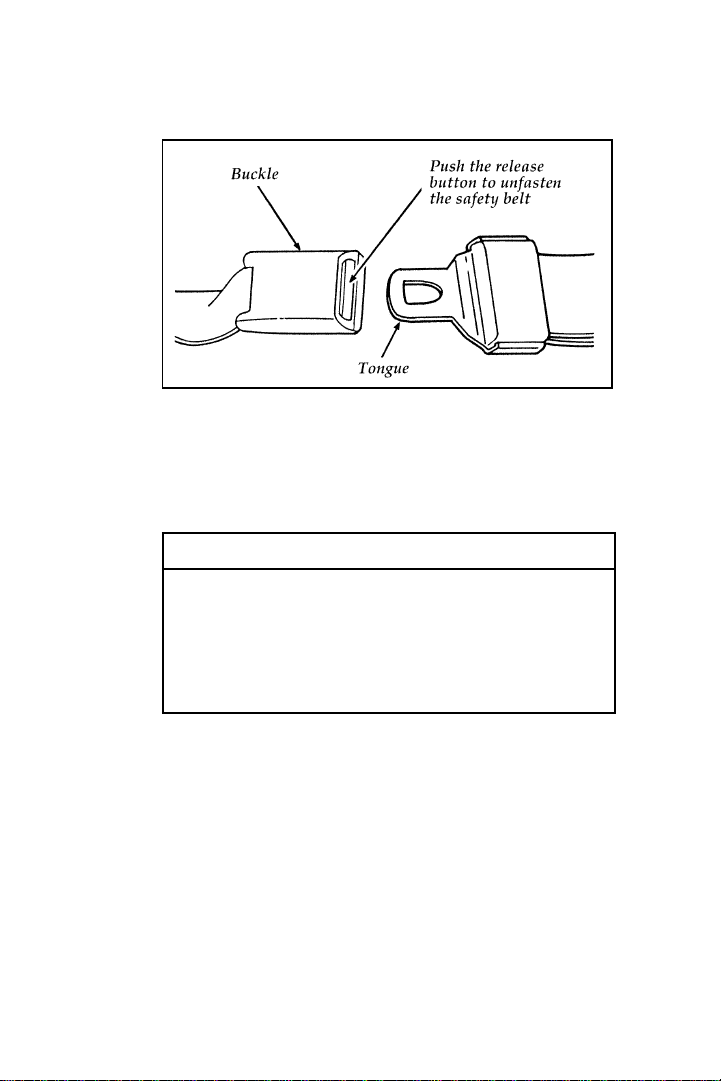
made up of one buckle and one
tongue that are designed to be used
as a pair. Failure to follow these
precautions could increase the risk
and/or severity of injury in a
collision.
10
Page 14
RWARNING
Never drive or ride with a twisted or
jammed safety belt. If you cannot
untwist or unjam the safety belt, see
the nearest qualified technician
immediately.
RWARNING
Children should always ride with the
seatback in the fully upright
position. When the seatback is not
fully upright, there is a greater risk
that the child will slide under the
safety belt and be seriously injured
in a collision.
RWARNING
Never let a passenger hold a child on
his or her lap while the vehicle is
moving. The passenger cannot protect
the child from injury in a collision.
Lock the doors of your vehicle before driving to
lessen the risk of the door coming open in a
collision.
Combination Lap and Shoulder
Belts
While your vehicle is in motion, the combination
lap and shoulder belt adjusts to your movement.
However, if you brake hard, turn hard, or if
your vehicle receives an impact of 5 mph
(8 km/h) or more, the lap and shoulder belt
locks and helps reduce your forward movement.
11
Page 15
After you get into your vehicle, close the door
and lock it. Then adjust the seat to the position
that suits you best.
Pull the combination lap/shoulder belt from the
retractor so that the shoulder portion of the belt
crosses your shoulder and chest. Be sure the belt
is not twisted. If it is, remove the twist. Insert
the belt tongue into the proper buckle until you
hear a snap and feel it latch. Make sure the
tongue is securely fastened to the buckle by
pulling on tongue.
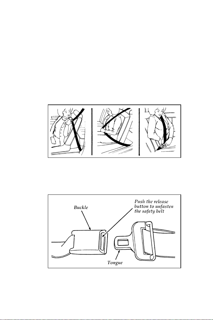
Fastening the front seat combination lap and shoulder belt
NOTE: Be sure to read and understand
Important Safety Belt Information at
the beginning of this chapter.
Unfastening the combination lap and shoulder belts —
front and rear outboard seating positions
12
Page 16

While the belt retracts, guide the tongue to its
original position to prevent it from striking you
or the vehicle.
Safety Belts for Front Outboard Passenger
and Rear Outboard Seating Positions
(Except Wagon Rear-Facing Seat)
Your vehicle is equipped with a dual locking
mode retractor on the shoulder belt portion of
the combination lap/shoulder safety belt for the
front seat outboard passenger and rear outboard
passengers.
Dual locking mode retractors operate in two
ways:
Vehicle Sensitive (Emergency) Locking Mode
In this operating mode, the shoulder belt
retractor will allow the occupant freedom of
movement, locking tight only on hard braking,
hard cornering or impacts of approximately
5 mph (8 km/h) or more. The retractor can also
be made to lock by pulling on the belt.
Automatic locking mode
In this operating mode, the shoulder belt
retractor will be automatically locked and will
remain locked when the combination
lap/shoulder safety belt is buckled, and does not
allow the occupant freedom of movement. This
mode provides the following:
A tight lap/shoulder belt on the occupant.
❑
Child safety seat installation.
❑
RWARNING
Rear-facing infant seats should never
be placed in the front seats.
13
Page 17

This mode must be used when installing a child
safety seat on the front passenger seat and rear
outboard seats where dual locking retractors are
provided.
To switch the retractor from the emergency
locking mode to the automatic locking mode,
perform the following steps:
1. Buckle the lap/shoulder combination belt.
2. Grasp the shoulder portion of the belt and
pull downward until all of the belt is
extracted, and when allowed to retract, a
clicking sound will be heard. At this time,
the belt retractor is in the automatic locking
mode (child restraint mode).
3. A clicking sound will continue to be heard
as the belt is allowed to retract. This
indicates that the retractor is in the
automatic locking mode.
NOTE: When the combination lap/shoulder
belt is unbuckled and allowed to
retract completely, the retractor will
switch to the vehicle sensitive
(emergency) locking mode. See the
detailed instructions under Safety Seats
for Children in this chapter.
Shoulder Belt Height Adjustment
Driver and right front passenger
You can adjust the shoulder belt height to one of
five (5) positions.
To adjust the belt down, pinch the release
button. To adjust the belt up, slide the adjuster
up. (You do not have to pinch the release
button.)
14
Page 18
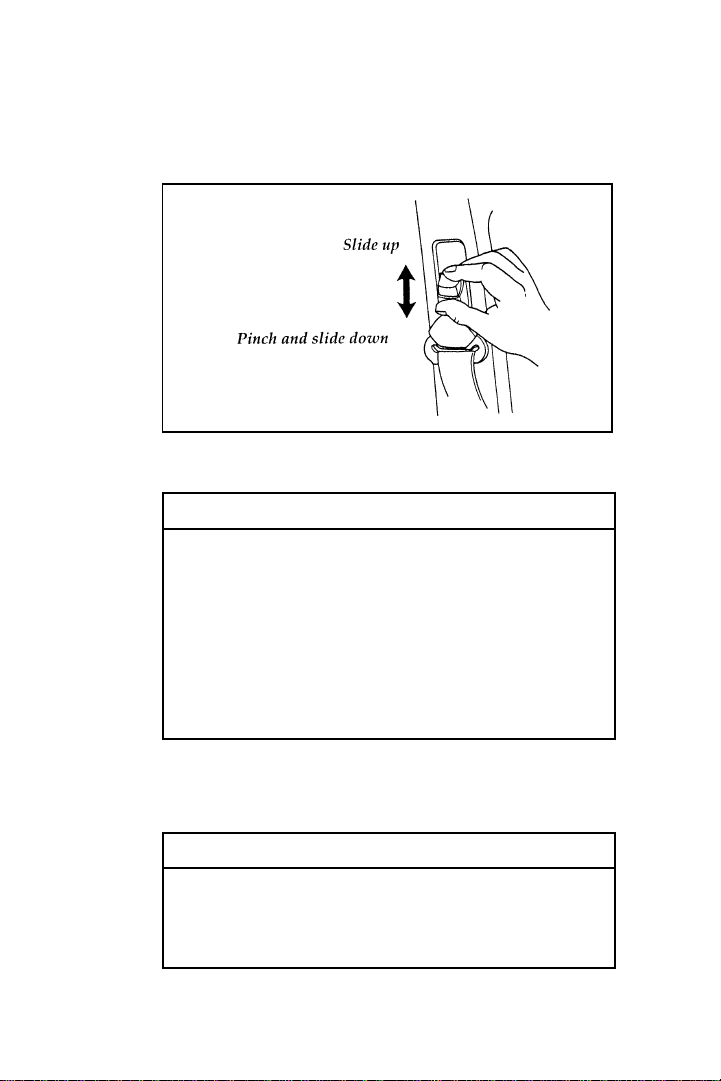
Make sure the adjuster is firmly in one of the
five positions. The belt should be adjusted up or
down until the belt rests on your shoulder near
your neck.
The shoulder belt height adjuster
RWARNING
Position the shoulder belt height
adjuster so that the belt rests across
the middle of your shoulder. Be sure
the shoulder belt is properly
positioned on your shoulder each
time you use the belt. If the shoulder
belt is off your shoulder, on your
upper arm or neck, there is a greater
risk of severe injury in a collision.
Safety Belts for Rear-Facing Occupants
(Wagon)
RWARNING
If you have a wagon, never use child
safety seats in the third seat. Safety
seats for children are not intended
for use in rear facing seats.
15
Page 19

Your vehicle is equipped with safety seat belts
containing a cinch tongue at the rear-facing
seating positions.
The locking cinch tongue will slide up and
down the belt webbing when the belt is in the
stowed position or while putting seat belts on.
When the locking cinch tongue of the
lap/shoulder combination seat belt is latched
into the buckle, the cinch tongue will allow the
lap portion to become shorter, but locks the
webbing in place to restrict it from becoming
longer.
Before you can reach and latch a combination
lap and shoulder belt having a cinch tongue into
the buckle, you may have to lengthen the lap
belt portion of it. To lengthen the lap belt, pull
some webbing out of the shoulder belt retractor.
While holding the webbing below the tongue,
grasp the tip (metal portion) of the tongue so
that it is parallel to the webbing and slide the
tongue upward. Provide enough lap belt length
so that the tongue can reach the buckle.
NOTE: If you grasp the tongue by the tongue
cover to lengthen the belt, the tongue
cover will grab the webbing, making it
difficult to slide.
To fasten a cinch tongue, pull the combination
lap and shoulder belt from the retractor so that
the shoulder belt portion of the safety belt
crosses your shoulder and chest. Be sure the belt
is not twisted. If the belt is twisted remove the
twist. Insert the belt tongue into the proper
buckle for your seating position until you hear a
snap and feel it latch. Make sure the tongue is
securely fastened to the buckle by pulling of the
tongue.
16
Page 20
RWARNING
Make sure that the lap belt is as low
around your hips as possible. Do not
wear the lap belt around your waist.
If you do not use the lap belts
properly, the risk of being injured in
a collision greatly increases.
RWARNING
All front and rear seat outboard
occupants (including pregnant
women) should wear lap and
shoulder belts, for optimum
protection in a collision.
RWARNING
Use the shoulder belt on the outside
shoulder only. Never wear the
shoulder belt under the arm. Never
swing it around your neck over the
inside shoulder. Never use a single
belt for more than one person.
Failure to follow these precautions
could increase the risk and/or
severity of injury in a collision.
Due to folding rear seats, sometimes the buckles
and tongues toward the center of the vehicle
may be hidden by the rear edge of the seat
cushion. Pull them out so they will be accessible.
While you are fastened in the seat belt, the
combination lap/shoulder belt with a cinch
tongue adjusts to your movement. However, if
you brake hard, turn hard, or if your vehicle
receives an impact of 5 mph (8 km/h) or more,
17
Page 21
the safety belt will become locked and help
reduce your forward movement.
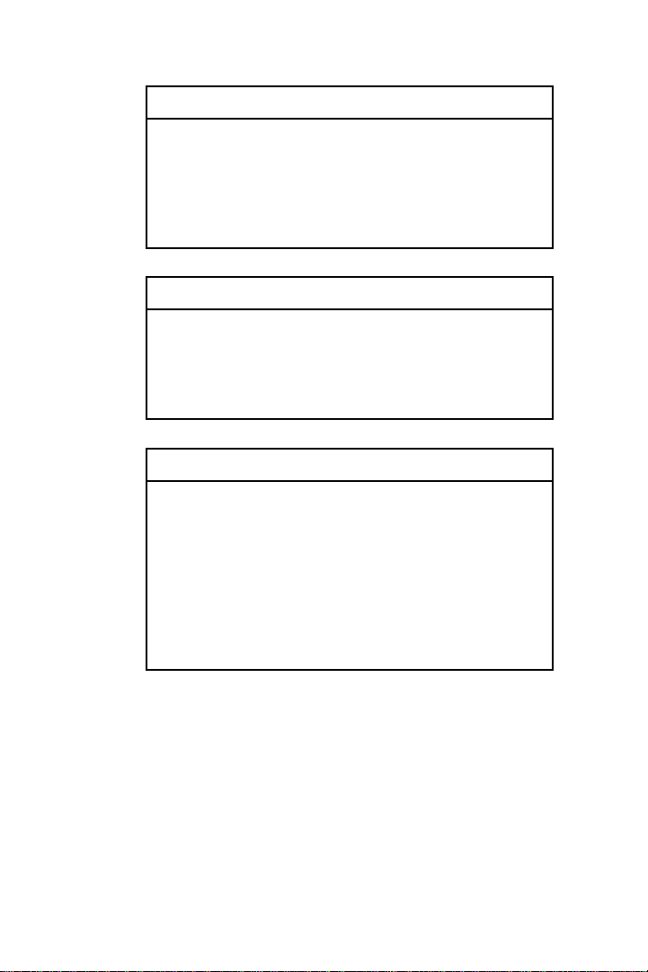
To unfasten the belt, push the red release button
on the end of the buckle. This allows the tongue
to unlatch from the buckle. While the belt
retracts, guide the tongue to its original position
to prevent it from striking you or the vehicle.
Unfastening the combination lap and shoulder belts for the
rear-facing third seat (wagon)
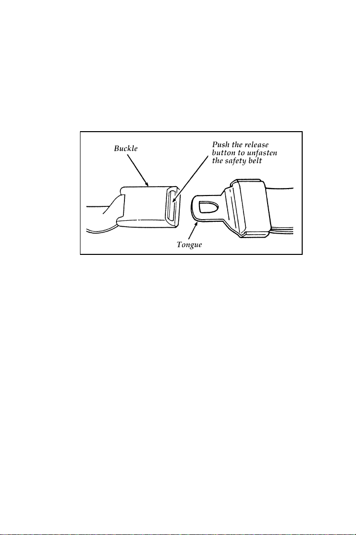
Center Occupant Rear Safety Belt (Sedan)
The safety belt in the center rear seating position
has a detachable shoulder belt.
To attach the shoulder belt to the lap belt, pull
the shoulder belt out from the retractor in the
seatback and insert the lap belt connecting pin
into the wide end of the key-slot on the
shoulder belt as shown in Figure 1. Pull the
connecting pin into the narrow end of the
key-slot until you hear a snap and feel it latch.
See Figure 2. Make sure the shoulder belt is
securely fastened to the lap belt by pulling up
on the shoulder belt.
18
Page 22
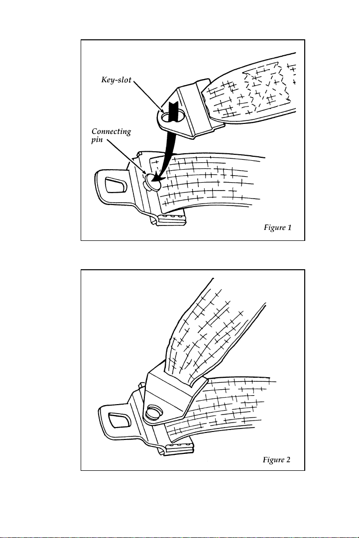
The reverse side of the lap belt and the detachable
shoulder belt
The reverse side of the shoulder belt attached to the lap belt
19
Page 23

RWARNING
The rear center lap belt must be
tightened separately from the
shoulder strap. The lap belt must fit
snugly, and as low as possible
around the hips. Do not wear around
your waist. For information about
adjusting the belt, see “LAP BELTS”
in this chapter.
Detach the shoulder belt before folding down
the passenger side rear seat. To detach the
shoulder belt, slide the connecting pin to the
wide end of the key-slot and lift the shoulder
belt off the connecting pin. As the shoulder belt
retracts, guide the belt so that it does not strike
you or the vehicle.
The lap belts in the center front seating position
(if equipped) and center rear seat (wagon) do
not adjust automatically. You must adjust them
to fit snugly and as low as possible around your
hips. Do not wear the lap belt around your
waist.
The front center seat belt buckle and tongue are
stowed in a pocket between the seat cushion and
seatback. Remove them from the stowage pocket
before fastening.
Pull the belt across your hips and insert the
tongue into the correct buckle on your seat
until you hear a snap and feel it lock. Make sure
the buckle is securely fastened.
If you need to lengthen the belt, unfasten it and
tip the belt tongue at a right angle to the belt.
Pull the belt tongue over your lap until it
reaches the buckle.
20
Page 24
If you need to shorten the belt, pull on the loose
end of the webbing until the belt fits snugly.
Unfastening the lap belts for the center front and center
rear seating positions
To unfasten the belt, push the release button on
the end of the buckle. This allows the tongue to
unlatch from the buckle.
RWARNING
Make sure that the lap belt is as low
around your hips as possible. Do not
wear the lap belt around your waist.
If you do not use the lap belts
properly, the risk of being injured in
a collision greatly increases.
Safety Belt Extension Assembly
For some people, the safety belt may be too
short even when it is fully extended. You can
add about eight inches (20 cm) to the belt length
with a safety belt extension assembly (part
number 611C22). Safety belt extensions are
available at no cost from your dealer.
This assembly is not for use in the wagon
rear-facing seat.
21
Page 25
RWARNING
The use of the safety belt extension
assembly, in the wagon rear-facing
seat will affect the performance of
the safety belts and increase the risk
of personal injury.
RWARNING
Use only extensions manufactured by
the same supplier as the safety belt.
Manufacturer identification is located
at the end of the webbing on the
label. Also, use the safety belt
extension only if the safety belt is
too short for you when fully
extended. Do not use extension to
change the fit of the shoulder belt
across the torso. Failure to follow
these instructions will affect the
performance of the safety belts and
increase the risk of personal injury.
Safety Belt Maintenance
Check the safety belt systems periodically to
make sure that they work properly and are not
damaged.
All safety belt assemblies, including retractors,
buckles, front seat belt buckle support assemblies
(slide bar) (if equipped), child safety seat tether
bracket assemblies (if equipped), and attaching
hardware, should be inspected after any
collision. Ford recommends that all safety belt
assemblies used in vehicles involved in a
collision be replaced. However, if the collision
22
Page 26
was minor and a qualified technician finds that
the belts do not show damage and continue to
operate properly, they do not need to be
replaced. Safety belt assemblies not in use
during a collision should also be inspected and
replaced if either damage or improper operation
is noted.
Cleaning the Safety Belts
Clean the safety belts with any mild soap
solution that is recommended for cleaning
upholstery or carpets. Do not bleach or dye the
belt webbing because this may weaken it.
System (SRS)
The driver and right front passenger air bags are
Supplemental Restraint Systems (SRS), provided
at these seating positions in addition to the
lap/shoulder belt, and are designed to
supplement the protection provided to properly
belted occupants in moderate to severe frontal
collisions. The supplemental air bag system does
not provide restraint to the lower body.
The Importance of Wearing Safety Belts
RWARNING
ALWAYS WEAR YOUR SAFETY
BELT!
23
Page 27

RWARNING
All occupants of the vehicle,
including the driver, should always
wear their safety belts, whether or
not an air bag Supplemental
Restraint System is also provided at
their seating position. Failure to do
so may increase the risk of severe
injury or death in the event of a
collision.
There are four very important reasons to use
safety belts even with an air bag system. Use
your safety belts to:
help keep you in the proper position (away
❑
from the air bag) when it inflates
reduce the risk of harm in rollover, side or
❑
rear impact collisions, because an air bag is
not designed to inflate in such situations
reduce the risk of harm in frontal collisions
❑
that are not severe enough to activate the
supplemental air bag
reduce the risk of being thrown from your
❑
vehicle
The Importance of Being Properly Seated
In a collision, the air bag must inflate extremely
fast to help provide additional protection for
you. In order to do this, the air bag must inflate
with considerable force. If you are not seated in
a normal riding position with your back against
the seatback, the air bag may not protect you
properly and could possibly hurt you as it
inflates.
24
Page 28

RWARNING
If a passenger is not properly seated
and restrained, an inflating air bag
could cause serious injury.
RWARNING
Rear-facing infant seats should never
be placed in the front seat.
In rear-facing infant seats, the infant’s head is
closer to the air bag. The force of the rapidly
inflating air bag could push the top of the
rear-facing seat against the vehicle seatback or
center armrests (if so equipped), or center
console (if so equipped). REAR-FACING
INFANT CARRIERS MUST ALWAYS BE
SECURED IN THE REAR SEAT, and other child
safety seats and infant seats should be secured in
the rear seat whenever possible.
25
Page 29
RWARNING
Your vehicle is equipped with a right
front passenger air bag. Front
passengers, especially children and
small adults, should never sit on the
edge of the seat, stand near the glove
compartment of the instrument panel,
or lean over with their faces near the
glove compartment when the vehicle
is moving. All occupants should sit
with their backs against the seatback
and use the safety belts. Children
weighing less than 40 lbs. (18 kg)
should use child or infant seats.
Forward-facing child seats must have
the passenger seat moved as far back
from the instrument panel as
possible. REAR-FACING INFANT
SEATS SHOULD NEVER BE USED
IN THE FRONT SEAT, BECAUSE
THE FORCE OF THE RAPIDLY
INFLATING PASSENGER AIR BAG
COULD PUSH THE TOP OF THE
REAR-FACING SEAT AGAINST
THE VEHICLE SEATBACK, CENTER
ARMRESTS OR CONSOLE (IF SO
EQUIPPED). REAR-FACING
INFANT SEATS MUST ALWAYS BE
PLACED IN THE REAR SEAT.
26
Page 30

RWARNING
Do not place objects or mount
equipment on or near the air bag
module covers (identified by the
letters “SRS”) on the steering wheel
and instrument panel, or in front seat
areas that may come in contact with a
deploying air bag, because any such
objects could cause harm if the
vehicle is in a collision severe
enough to cause the air bag to
inflate. Failure to follow this
instruction may increase the risk of
personal injury in the event of a
collision.
For further information about the proper
mounting of equipment in the front seat of this
vehicle, please refer to Ford’s brochure entitled
Some Important Information About Air Bag
Supplemental Restraint System which can be
obtained by calling Helm Inc. at 1-800-782-4356.
Ask for brochure FPS-8602.
For additional important safety information on
the proper use of seat belts, child seats, and
infant seats, please read the other sections of this
part of the Owner Guide, especially sections
entitled Safety Belts for Children and Safety Seats
for Children.
27
Page 31

How the Air Bag Supplemental Restraint
System Operates
The Air Bag Supplemental Restraint System
consists of the Driver and Passenger air bags,
impact sensors, a system diagnostic module, a
readiness light and tone, and the electrical
wiring which connects the components.
The driver air bag is in the center of the steering
wheel. The front passenger seat air bag is
located in the center of the instrument panel
ledge above the glove compartment. Both air
bags are designed to stay out of sight until they
are activated.
The location of air bags and warning labels
If a collision occurs, the sensors sense the
severity of the impact and activate the air bags if
necessary. The air bag system is designed to
deploy in frontal and front-angled collisions
more severe than hitting a parked vehicle (of
28
Page 32

similar size and weight) head-on at about
28 mph (45 km/h). Because the system senses
the crash severity rather than vehicle speed,
some frontal collisions at speeds above 28 mph
(45 km/h) will not inflate the air bag.
When the sensors activate the system, the air
bags inflate rapidly, filling with non-toxic gas
mixture in a fraction of a second. Immediately
after inflation, the air bags deflate by releasing
the gas mixture through vent holes. The whole
process takes place in a matter of seconds.
RWARNING
Several air bag system components
get hot after inflation. Do not try to
touch them after inflation.
Inflated driver-side air bag
29
Page 33

Inflated passenger-side air bag
RWARNING
The air bag will inflate only once.
The system is designed to function
on a one-time-only basis. If the air
bag is inflated, THE AIR BAG WILL
NOT FUNCTION AGAIN AND
MUST BE REPLACED
IMMEDIATELY. If the air bag is not
replaced, the unrepaired area will
increase the risk of injury in a
collision.
To ensure that the air bag system will operate as
intended in a crash, the system is equipped with
a diagnostic module. The diagnostic module
monitors its own circuits, the air bag electrical
system, the air bag readiness light, the air bag
power, and the air bag inflators.
30
Page 34

The air bag system uses a readiness light on the
instrument cluster and a tone to indicate the
condition of the system. When you turn the
ignition key to the ON position, this light will
illuminate for approximately six (6) seconds and
then turn off. This indicates that the system is
operating normally. NOTE: Maintenance of the
air bag system is not required.
A problem with the system is indicated by one
or more of the following:
the readiness light will either flash or stay lit,
❑
or it will not light immediately after ignition
❑
is turned on,
or a group of five beeps will be heard. The
❑
tone pattern will repeat periodically until the
problem and light are repaired.
If any of these things happen, have the air bag
system serviced at your Ford or Lincoln-Mercury
dealer immediately. Unless serviced, the Air Bag
Supplemental Restraint System may not function
properly in the event of a collision.
RWARNING
Do not attempt to service, repair, or
modify the Air Bag Supplemental
Restraint System; tampering could
cause activation of the system and
increase the risk of personal injury.
DO NOT REPLACE OR
OTHERWISE TAMPER WITH THE
AIR BAG FUSES. For servicing of
the Air Bag Supplemental Restraint
System, see your Ford or
Lincoln-Mercury dealer.
31
Page 35

Disposal of air bags or air bag equipped
vehicles
For disposal of air bags or air bag equipped
vehicles, see your local Ford or Lincoln-Mercury
dealer. Air bags MUST be disposed of by
qualified personnel.
In the U.S. and Canada, you are required by law
to use safety restraints for children. If small
children ride in your vehicle — this generally
includes children who are four years old or
younger and who weigh 40 pounds (18 kg) or
less — you must put them in safety seats that
are made specially for children. Safety belts
alone do not provide maximum protection for
these children. Check your local and state laws
for specific requirements.
RWARNING
Never let a passenger hold a child on
his or her lap while the vehicle is
moving. The passenger cannot protect
the child from injury in a collision.
Make sure children sit where they
can be properly restrained. If they
are not restrained, the risk of their
being injured in a collision greatly
increases.
RWARNING
Never let children or adults ride in
the cargo area of your vehicle. Make
sure that they sit where they can be
properly restrained. If they are not
restrained, the risk of their being
injured in a collision greatly
increases.
32
Page 36

RWARNING
When possible, put children in the
rear seat of your vehicle. Accident
statistics suggest that children are
safer when properly restrained in the
rear seating positions than in the
front seating positions.
RWARNING
When using any infant or child
restraint system, it is important that
you follow the instructions and
warnings provided by the
manufacturer concerning its
installation and use. Failure to follow
each of the restraint manufacturer’s
instructions could increase the risk or
severity of an injury in the event of
a collision or sudden stop.
Safety belts and seats can become hot
in a vehicle that has been closed up
in sunny weather; they could burn a
small child. Check seat covers and
buckles before you place a child
anywhere near them.
RWARNING
Never leave a child unattended in
your vehicle. Always remove the key
from the ignition and take it with
you.
33
Page 37

Safety Seats for Children
Use a safety seat that is recommended for the
size and weight of the child. Always follow the
safety seat manufacturer’s instructions when
installing and using the safety seat.
Ford recommends the use of a child safety seat
having a top tether strap. Install the child safety
seat in a seating position which is capable of
providing a tether anchorage. For more
information on top tether straps see Attaching
Safety Seats With Tether Straps in this chapter.
When installing a child safety seat, be sure to
use the correct safety belt buckle for that seating
position, and make sure the tongue is securely
fastened in the buckle.
RWARNING
Your vehicle is equipped with a right
front passenger air bag.
REAR-FACING INFANT SEATS
SHOULD NEVER BE USED IN THE
FRONT SEAT, BECAUSE THE
FORCE OF THE RAPIDLY
INFLATING PASSENGER AIR BAG
COULD PUSH THE TOP OF THE
REAR-FACING SEAT AGAINST THE
VEHICLE SEATBACK, OR CENTER
CONSOLE (IF SO EQUIPPED), OR
CENTER ARMRESTS (IF SO
EQUIPPED). ALWAYS PLACE
REAR-FACING INFANT SEATS IN
THE REAR SEAT. When using
forward-facing child seats in the front
seat, always move the passenger seat
as far back from the instrument panel
as possible. Failure to follow these
warnings could result in injury to the
child.
34
Page 38

RWARNING
All child restraint systems are
designed to be secured in vehicle
seats by lap belts or by the lap
portion of a lap-shoulder belt. If you
do not properly secure the safety seat
to the vehicle, the risk is greater that
a child, occupying the seat during a
collision or sudden stop, will be
injured. An unsecured safety seat
could also injure other passengers in
the vehicle.
RWARNING
Carefully follow all of the
manufacturer’s instructions that come
with the safety seat that you put in
your vehicle. Make sure that the
shoulder belt (if provided at the
seating position where the safety seat
is being used) does not cross or rest
in front of the child’s face or neck. If
you do not install and use the safety
seat properly, the child may be
injured in a sudden stop or collision.
RWARNING
If you have a wagon, never use child
safety seats in the third seat. Safety
seats for children are not intended
for use in rear facing seats.
35
Page 39

RWARNING
Always keep the buckle release
button pointing upward and away
from the child seat, with the tongue
between the child seat and the
release button as shown in the
following illustration. Failure to
follow these instructions could result
in accidental unbuckling of the safety
belt if the child safety seat hits the
release button. Release of the safety
belt could result in serious injuries.
Safety belt buckle placement for child seats
36
Page 40

Installing Child Safety Seats in the Front
Passenger Seat and Outer Rear Seating
Positions
Your vehicle is equipped with a dual locking
mode retractor on the shoulder belt portion of
the combination lap/shoulder safety belt for the
front passenger seat and rear outer seats. The
automatic locking mode must be used when
installing a child seat or infant carrier in the
front passenger seat or rear outer seats.
RWARNING
Never install a rear-facing child seat
or infant carrier in the right front
passenger seat.
If you choose to install a child safety seat in the
front seating position, move vehicle seat as far
back as possible.
1. Position the child seat on the passenger seat
of the vehicle.
37
Page 41

2. Pull down on shoulder belt, then grasp
shoulder belt and lap belt together. Figure 1.
38
Page 42

3. While holding the shoulder and lap belt
portions together, route the tongue through
the child seat according to the child seat
manufacturer’s instructions. See Figure 2. Be
sure that the belt webbing is not twisted.
Routing the lap/shoulder belt
39
Page 43

Buckling the belt
40
Page 44

4. Grasp the shoulder portion of the belt and
pull downward until all of the belt is
extracted and a click is heard. At this time,
the retractor is in the automatic locking
mode (child seat restraint mode). Figure 4.
Setting the retractor to automatic locking mode
41
Page 45

5. Allow the belt to retract. Pull up on the
shoulder webbing. A clicking sound will be
heard as the belt retracts. This indicates the
retractor is in the automatic locking mode.
Push down on the child seat while you pull
up on the belt to remove any slack in the
belt. Figures 5 and 6.
42
Page 46

43
Page 47

6. Before placing the child in the child seat,
forcibly tilt the seat from side to side, and
tug it forward to make sure that the seat is
securely held in place, Figure 7.
Checking that the seat is secure
44
Page 48

7. Double check that the retractor is in the
automatic locking mode. Try to pull more
belt out of the retractor. If you cannot, the
belt is in the automatic locking mode,
Figure 8.
Checking the retractor
8. Check to make sure that the child seat is
properly secured prior to each use. If the
retractor is not locked, repeat steps 4
through 7.
NOTE: To remove the retractor from automatic
lock mode, allow seat belt to retract
fully to its stowed position and the
retractor will automatically switch back
to the vehicle sensitive locking mode
for normal adult usage.
45
Page 49

RWARNING
When using any infant or child
restraint system, it is important that
you follow the instructions and
warnings provided by the
manufacturer concerning its
installation and use. Failure to follow
each of the restraint manufacturer’s
instructions could increase the risk or
severity of an injury in the event of
a collision or sudden stop.
Attaching Safety Seats With Tether Straps
Some manufacturers make safety seats that
include a tether strap that goes over the back of
the vehicle seat and attaches to an anchoring
point. Other manufacturers offer the tether strap
as an accessory. Contact the manufacturer of
your child safety seat for information about
ordering a tether strap.
Front Seats
To install a tether from a child safety seat in the
front seat:
1. Buckle the lap/shoulder belt (in the seat
directly behind the front passenger seat in
which the child safety seat will be installed).
2. Pull all the stored belt out of the rear seat
retractor to switch the retractor to automatic
locking mode.
3. Let the retractor wind up the slack from the
lap/shoulder belt.
46
Page 50

4. Install the child safety seat in the front seat.
Refer to the previous section on Installing
Safety Seats. Hook the tether strap hook
around the webbing near the center of the
shoulder portion of the locked lap/shoulder
belt.
5. Tighten the tether strap.
Rear Seats
If you use a tethered safety seat on one of the
rear seats, you can anchor the strap to the
appropriate tether anchor directly behind that
seat position.
Tether anchorage hardware
Attachment holes (at each rear outboard seating
position) have been provided in your vehicle to
attach anchor hardware, if required. Kits can be
obtained at no charge from any Ford or
Lincoln-Mercury dealer.
Be sure to follow the child safety seat
manufacturer’s instructions.
RWARNING
Tighten the anchor according to
specifications. Otherwise, the safety
seat may not be properly secured and
the child may be injured in a sudden
stop or collision.
In a station wagon, you simply attach the tether
strap to one of the anchors that are already
installed for you.
47
Page 51

Tether anchorage hardware
All wagons have a tether anchor installed for
each of the second row seating positions.
Finding the tether anchors in the wagon
1. Behind the second seat, find the plastic
snap-on covers for the floor anchors.
2. Use a screwdriver or coin to snap the covers
off the anchor in a rearward and upward
direction. Remove the covers completely.
3. Snap the tether strap hook onto the
U-shaped tether anchor.
48
Page 52

Built-In Child Seat (Wagon — If equipped)
The second row seat may include an optional
built-in child safety seat on the passenger side.
The child restraint is to be used only by children
who are at least one year old, weigh between 9
and 27 kilograms (20 and 60 pounds) and whose
shoulders (top) are below the shoulder harness
slots in the seatback.
If your child is less than one year old or weighs
less than 9 kilograms (20 pounds), always use a
rear facing infant or convertible seat because a
child of that size is not sufficiently developed to
withstand crash forces in a front facing position.
Follow the specific manufacturer’s instructions
for weight and height restrictions.
Children must be properly buckled before riding
in the vehicle. It is the law in every state and
province. This child seat conforms to all
Federal/Canadian motor vehicle safety
standards.
Built-in child seat belt retractors
The belts on the built-in child seat are equipped
with a retractor that locks when both belt
tongues are latched into the crotch safety belt
buckled.
The retractor will automatically snug the belts
around the child. Frequently check the child
seat’s lap and shoulder harness belts for correct
placement and tightness. Use the child seat only
if the harness belts will stay snug with a child
buckled in the seat. If belts do not remain snug,
take the vehicle to the dealer for child seat
repair.
49
Page 53

RWARNING
Always adjust the lap and shoulder
harness belts provided with this
child seat snugly around your child.
Never leave your child unattended in
the vehicle.
The child seat’s metal and plastic
parts can become very hot when left
in the sun. These can cause burns to
unprotected skin.
Failure to follow all of the
instructions on the use of this child
restraint system can result in your
child striking the vehicle’s interior
during a sudden stop or crash.
How to use the Built-In Child Seat
Read the following procedures and all of the
labels on the Built-In Child Seat before using the
seat.
RWARNING
Never use the Built-In Child Seat as
a booster cushion with the adult
safety belts. A child using the adult
belts could slide forward off the
front edge of the child seat cushion
and out from under the adult safety
belts.
50
Page 54

1. Pull and release flap from top of seatback.
See Figure 1.
Figure 1: Releasing the flap
2. Grasp the child seat at the top of the
seatback and pull the top forward to release
the latch. See Figure 2.
NOTE: The child seat cannot be opened unless
the seatback is latched in the upright
position.
Figure 2: Releasing the latch
3. Continue to unfold the child seat until it
rests on the seat as shown in Figure 3.
51
Page 55

Figure 3: Opening the built-in child seat
4. Read the information and warnings on the
child seat cushion and shoulder safety belt.
Refer to Figure 4. Check the child’s size,
weight and age to be sure the child is not
too small or too large for the child seat.
Figure 4: Child seat information and warnings
5. If connected, squeeze the top and the bottom
of the right half of the chest clip and pull to
separate both halves.
6. Place the child on the child seat and position
the shoulder belts over each shoulder. Refer
to Figure 5.
52
Page 56

Figure 5: Shoulder safety belt placement on the child
NOTE: Read the following steps carefully to
become familiar with the indicator
windows located on each safety belt
tongue and the chest clip. When either
of the tongues or the chest clip is
unbuckled, the color red appears in the
window. When the tongues or chest
clip are securely buckled, the color
green appears.
7. Insert either the left or right safety belt
tongue into the single opening of the crotch
safety belt buckle as shown in Figure 6. (It
does not matter which tongue is inserted
first.) Then insert the other tongue. Allow
belts to retract and fit snugly.
NOTE: The indicator window on each tongue
must appear green when buckled.
NOTE: If a belt locks during extraction, allow
belts to retract FULLY and repeat
procedure.
RWARNING
If both tongues do not latch in the
buckle, do not use the child seat. See
your dealer for repairs.
53
Page 57

Figure 6: Fastening the crotch safety belt buckle
54
Page 58

8. Fasten both halves of the chest clip below
the child’s shoulders and adjust it to
comfortably hold the shoulder belts in place
on the child’s chest. The color green must
appear in the indicator window when
fastened. (The purpose of this clip is to
position the shoulder belts correctly on the
child’s shoulders. The clip can be easily
pulled apart and is designed to pull apart
during a collision. The clip helps keep the
belts on the shoulders of a sleeping or
squirming child.) Refer to Figure 7.
55
Page 59

Figure 7: Securing the chest clip
56
Page 60

9. Pull the shoulder belts out to ensure that the
crotch safety belt buckle is securely fastened
and the retractor is locked. Refer to Figure 8.
Figure 8: Checking for securely latched buckle and locked
retractor
10. If the belts become too tight, unbuckle the
crotch safety belt buckle allow belts to
retract, then reinsert both belt tongues.
To remove the child from the built-in child
seat:
1. Squeeze the tabs on the top and bottom of
the chest clip and pull the halves apart to
open the chest clip. Refer back to Figure 7.
2. Press the release button on the crotch safety
belt buckle.
3. Slide the shoulder belts off the child’s
shoulders and remove the child. Refer back
to Figure 5.
57
Page 61

To stow the built-in child seat:
1. Return the child seat cushion to the upright
position.
2. Press firmly in the center and top of the
child seat to place it in the stowed position.
3. Reattach the flap on the child seat to the top
of the seatback.
The seat can now be used by an adult or the
seatback can be folded down.
NOTE: The seatback cannot be folded down
unless the child seat is fully stowed.
Inspection after a collision
RWARNING
All built-in child restraints, including
seats, buckles, retractors, seat latches,
interlocks, and attaching hardware
should be inspected by a qualified
Dealer technician after any collision.
If the child seat was in use during a
collision, Ford recommends replacing
it. However, if the collision was
minor and a qualified technician
finds that the child restraints do not
show damage and continue to
operate properly, they do not need to
be replaced. Built-in child seats not
in use during a collision should also
be inspected and replaced if either
damage or improper operation is
noted.
Built-in child seat maintenance
Regularly inspect the lap and shoulder belts
system of your child seat. See your Ford dealer
if the shoulder belt webbing is frayed, or if the
58
Page 62

buckle and tongue are damaged and/or do not
function properly.
Cleaning
Your built-in child seat may be cleaned with
mild soap and water. Do not use household
cleaners as they may weaken the webbing or
damage the plastic parts. For your convenience,
the liner is removable and can be
machine-washed and air-dried.
Safety Belts for Children
Children who are too large for child safety seats
should always wear safety belts. (See instructions
with your child seat, or contact its manufacturer,
to determine maximum size of child that will
safely fit in the seat.)
RWARNING
If safety belts are not properly worn
and adjusted as described, the risk of
serious injury to the child in a
collision will be much greater.
RWARNING
If the shoulder belt portion of one of
the lap and shoulder belts can be
positioned so that it does not cross or
rest in front of the child’s face or
neck, the child should wear the lap
and shoulder belt. Moving the child
closer to the center of the vehicle
may help provide a good shoulder
belt fit.
59
Page 63

To improve the fit of lap and shoulder belts on
children who have outgrown child safety seats,
Ford recommends use of a belt-positioning
booster seat that is labelled as conforming to all
Federal motor vehicle safety standards.
Belt-positioning booster seats raise the child and
provide a shorter, firmer seating cushion that
encourages safer seating posture and better fit of
lap and shoulder belts on the child. A
belt-positioning booster should be used if the
shoulder belt rests in front of the child’s face or
neck, or if the lap belt does not fit snugly on
both thighs, or if the thighs are too short to let
the child sit all the way back on the seat cushion
when the lower legs hang over the edge of the
seat cushion. You may wish to discuss the
specific needs of your child with your
pediatrician.
RWARNING
Do not use a belt-positioning booster
with a lap-only belt.
RWARNING
Lap belts and the lap belt portion of
lap and shoulder belts should always
be worn snugly and below the hips,
touching the child’s thighs.
RWARNING
Children should always ride with the
seatback in the fully upright
position. When the seatback is not
fully upright, there is a greater risk
that the child will slide under the
safety belt and be seriously injured
in a collision.
60
Page 64

Starting Your Sable
Understanding the Positions of the Ignition
The positions of the key in the ignition
ACCESSORY allows some of your vehicle’s
electrical accessories such as the radio and the
windshield wipers to operate while the engine is
not running.
LOCK locks the steering wheel. It also locks the
gearshift for all vehicles with an automatic
transaxle.
The automatic transaxle gearshift must be in P
(Park) to move the key to the LOCK position.
61
Page 65

LOCK is the only position that allows you to
remove the key. The LOCK feature helps to
protect your vehicle from theft.
If the key is stuck in the LOCK position, move
your steering wheel left or right until the key
turns freely.
OFF allows you to shut off the engine and all
accessories without locking the steering wheel or
the automatic transaxle gearshift lever.
ON allows you to test your vehicle’s warning
lights (except the brake system warning light) to
make sure they work before you start the
engine. The key returns to the ON position once
the engine is started and remains in this position
while the engine runs.
START cranks the engine. Release the key once
the engine starts so that you do not damage the
starter. The key should return to ON when you
release it. The START position also allows you
to test the brake warning light.
Removing the Key From the Ignition
Procedures for removing the key from the
ignition will be the same for both the columnand console-mounted gearshifts.
1. Put the gearshift in P (Park).
2. Set the parking brake fully.
3. Turn the ignition to the LOCK position.
4. Remove the key.
If you have difficulty in turning the key, rotate
the steering wheel slightly because it may be
binding.
If the driver’s door is open while the key is still
in the ignition, a warning chime sounds.
62
Page 66

RWARNING
Before you leave the driver’s seat,
make sure that the gearshift is
latched in P (Park). Set the parking
brake fully and shut off the engine.
Do not park your vehicle in N
(Neutral). If you do not take these
precautions, your vehicle may move
suddenly and injure someone.
Do not leave children, unreliable
adults, or pets alone in your vehicle.
They could accidentally injure
themselves or others through
inadvertent operation of the vehicle.
Further, on hot, sunny days
temperatures in a closed vehicle
could quickly become high enough
to cause severe and possibly fatal
injuries to people as well as animals.
63
Page 67

Preparing to Start Your Vehicle
RWARNING
Do not start your vehicle in a closed
garage or other enclosed area.
Exhaust fumes are toxic. Always open
the garage door before you start the
engine. See Guarding Against Exhaust
Fumes in this chapter for more
instructions.
Before you start your vehicle, do the following:
1. Make sure you and all your passengers
buckle your safety belts. See Safety Restraints
in the Index for more details.
2. Make sure your headlamps and other
accessories are turned off and the parking
brake is set.
3. Make sure that the gearshift is in P (Park)
before you turn the key.
Before you start your vehicle, you should test
the warning lights on the instrument panel to
make sure that they work. Refer to the Warning
Lights and Gauges chapter.
Starting Your Engine
To start your engine:
1. Follow the steps under Preparing to Start
Your Vehicle at the beginning of this section.
2. Turn the ignition key to the ON position.
3. DO NOT depress the accelerator pedal when
starting your engine. DO NOT use the
accelerator while the vehicle is parked.
64
Page 68

4. Turn the key to the START position
(cranking) until the engine starts. Allow the
key to return to the ON position after the
engine has started.
rotate the steering wheel slightly because it
may be binding.
For a cold engine:
At temperatures 10˚F (-12˚C) and below: If
❑
the engine does not start in fifteen (15)
seconds on the first try, turn the key to OFF,
wait approximately ten (10) seconds so you
do not flood the engine, then try again.
At temperatures above 10˚F (-12˚C): If the
❑
engine does not start in five (5) seconds on
the first try, turn the key to OFF, wait
approximately ten (10) seconds so you do not
flood the engine, then try again.
For a warm engine:
Do not hold the key in the START position
❑
for more than five (5) seconds at a time. If
the engine does not start within five (5)
seconds on the first try, turn the key to the
OFF position. Wait a few seconds after the
starter stops, then try again.
Whenever you start your vehicle, release the key
as soon as the engine starts. Excessive cranking
could damage the starter or flood the engine.
After you start the engine, let it idle for a few
seconds. Keep your foot on the brake pedal and
put the gearshift lever in gear. Release the
parking brake. Slowly release the brake pedal
and drive away in the normal manner.
65
Page 69

NOTE: Your vehicle is equipped with an
automatic transaxle and has an
interlock that prevents you from
shifting out of P (Park) unless your
foot is on the brake pedal.
If the engine does not start after two attempts:
1. Turn the ignition key to the OFF position.
2. Press the accelerator all the way to the floor
and hold it.
3. Turn the ignition key to the START position.
4. Release the ignition key when the engine
starts.
5. Release the accelerator gradually as the
engine speeds up. Then drive away in the
normal manner.
If the engine still does not start, the fuel pump
shut-off switch may have been triggered. For
directions on how to reset the switch see Fuel
Pump Shut-Off Switch later in this chapter.
A computer system controls the engine’s idle
speed. When you start your vehicle, the engine’s
idle speed normally runs high. These faster
engine speeds will make your vehicle move
slightly faster than its normal idle speed. It
should, however, slow down after a short time.
If it does not, have the idle speed checked.
66
Page 70

RWARNING
If the engine idle speed does not
slow down automatically, do not
allow your vehicle to idle for more
than 10 minutes. Have the vehicle
checked. Extended idling at high
engine speeds can produce very high
temperatures in the engine and
exhaust system, creating the risk of
fire or other damage to the vehicle
and may possibly result in personal
injury.
RWARNING
Do not park, idle, or operate your
vehicle in tall, dry grass, or other dry
ground areas. The high heat
generated by engine and emissions
components could start a ground fire.
If you consistently start your vehicle in subzero
temperatures, use an engine block heater (if
your vehicle has this option).
Engine Block Heater (If equipped)
(Standard in Canada)
Engine block heaters are strongly recommended
if you live in a region where temperatures reach
-10˚F (-23˚C) or below. An engine block heater
warms the engine coolant, which improves
starting, warms up the engine faster, and allows
the heater-defrost system to respond quickly.
To turn the heater on, simply plug it into a
grounded 110-volt outlet. Ford recommends that
you use a 110-volt circuit that is protected by a
ground fault circuit interrupter.
67
Page 71

For best results, plug the heater in at least three
hours before you start your vehicle. Using the
heater for longer than three hours will not
damage the engine, so you can plug it in at
night to start your vehicle the following
morning.
RWARNING
Do not use your heater with
ungrounded electrical systems or
two-pronged (cheater) adapters. You
can be injured by an electrical shock
if you use an ungrounded
connection.
Not Start or Does Not Start After
a Collision
Fuel Pump Shut-off Switch
If the engine cranks but does not start or does
not start after a collision, the fuel pump shut-off
switch may have been triggered. The shut-off
switch is a device intended to stop the fuel
pump when your vehicle has been involved in a
substantial jolt.
Once the shut-off switch is triggered, you must
reset the switch by hand before you can start
your vehicle. If you have a sedan, the switch is
on the right side of the trunk behind the trunk
liner. If you have a wagon, it is behind the
service panel on the right side of the cargo area.
68
Page 72

The right side of the trunk in the sedan
Inside the right side service panel in the wagon
69
Page 73

RWARNING
If you see or smell fuel, do not reset
the switch or try to start your vehicle.
You could injure yourself or others.
Have all the passengers get out of
the vehicle and call the local fire
department or a towing service.
If your engine cranks but does not start after a
collision or substantial jolt:
1. Turn the ignition key to the OFF position.
2. Check under the vehicle for leaking fuel.
3. If you do not see or smell fuel, push the red
reset button on the fuel pump shut-off
switch down.
4. Turn the ignition key to the ON position for
a few seconds, then turn it to the OFF
position.
5. Check under the vehicle again for leaking
fuel. If you see or smell fuel, do not start
your vehicle again. If you do not see or
smell fuel, you can try to start your vehicle
again.
6. Check all vehicle warning lights before
driving the vehicle.
Vehicles with automatic transaxles cannot be
started by pushing. Follow the directions under
If Your Vehicle Needs a Jump-Start in the Roadside
Emergencies Chapter.
70
Page 74

Carbon monoxide, although colorless and
odorless, is present in exhaust fumes. Take
precautions to avoid its dangerous effects.
RWARNING
Never idle the engine in closed areas.
Never sit in a parked or stopped
vehicle for more than a short period
of time with the engine running.
Exhaust fumes, particularly carbon
monoxide, may build up. These
fumes are harmful and could kill
you.
RWARNING
If you ever smell exhaust fumes of
any kind inside your vehicle, have
your dealer inspect and fix your
vehicle immediately. Do not drive if
you smell exhaust fumes. These
fumes are harmful and could kill
you.
Have the exhaust and body ventilation systems
checked whenever:
your vehicle is raised for service
❑
the sound of the exhaust system changes
❑
your vehicle has been damaged in a collision
❑
Improve your ventilation by keeping all air inlet
vents clear of snow, leaves, and other debris.
71
Page 75

If the engine is idling while you are stopped in
an open area for long periods of time, open the
windows at least one inch (2.5 cm). Also, adjust
the heating or air conditioning to bring in
outside air.
If you use the heater, set the fan speed on
❑
either medium or HI with the select knob on
either R (floor) or VENT.
If you use the air conditioner, set the fan
❑
speed on either medium or HI with the select
knob on A/C. (Do not use MAX A/C.)
If you use the automatic temperature control,
❑
set the fan speed on medium or high and
press the S (panel and floor) or R (floor)
manual override button. (Do not use AUTO
or MAX A/C.)
72
Page 76

Instrument Panel Controls
The main controls for the climate control system,
clock, and radio are in the oval Integrated
Control Panel on the instrument panel.
The controls for the lights and climate control air
registers are also on the instrument panel.
Clean the instrument panel lens and woodtone
trim with a soft cloth and a glass cleaner. Do
not use paper towel or any abrasive cleaner to
clean either the lens or the woodtone trim as
these may cause scratches.
NOTE: Any cleaner or polish that increases the
gloss (shine) of the upper part of the
instrument panel should be avoided.
The dull finish in this area is to help
protect the driver from undesirable
windshield reflection.
91
Page 77

Instrument panel
92
Page 78

Your vehicle has one of the following climate
control systems:
Manual Heating and Air Conditioning System
❑
Electronic Automatic Temperature Control
❑
(EATC) System
If you are not sure which system your vehicle
has, see the diagrams on the following pages.
Manual Heating and Air Conditioning
System
The knobs that control the manual heating and air
conditioning system
Fan speed knob
The fan speed knob controls the volume of air
circulated in the vehicle. There are four fan
speeds: LO, medium/low (first dot),
medium/high (second dot), and HI.
93
Page 79

Function selector knob
The function selector knob controls airflow to
the inside of the vehicle.
MAX A/C
MAX A/C uses recirculated air to cool the
vehicle. It allows for faster cooling but is noisier
than A/C. The airflow will be from the
instrument panel registers.
A/C
A/C uses outside air to cool the vehicle. It is
quieter that MAX A/C, but not as economical.
The airflow will be from the instrument panel
registers.
VENT
VENT brings in outside air through the
instrument panel registers. It can be used for
heating or ventilating.
OFF
In OFF, outside air is shut out and the fan will
not operate.
S (Panel and floor)
This brings in outside air through the instrument
panel registers and the front and rear floor
ducts. It can be used for heating or ventilating.
R (Floor)
This allows for maximum heating. The airflow is
from the front and rear floor ducts.
94
Page 80

P (Floor and defrost)
This brings in outside air through the floor ducts
and the windshield defroster ducts. It can be
used for heating or ventilation.
V (Defrost)
This brings in outside air through the
windshield defroster ducts. It can be used to
clear ice or fog from the windshield.
Temperature control knob
The temperature control knob may be adjusted
from cool (blue range) to warm (red range).
Electronic Automatic Temperature Control
System
The control for your Electronic Automatic
Temperature Control (EATC) is located at the
center of the instrument panel in the Integrated
Control Panel and will operate only when the
ignition is turned on to the ON position.
The EATC feature will maintain the temperature
you select and automatically control the airflow
for your comfort. It also allows you to override
the automatic operation with manual override
buttons.
95
Page 81

The Electronic Automatic Temperature Control System
96
Page 82

To turn your EATC on, press the AUTO button
or any of the six manual override buttons along
the bottom of the control.
To turn your EATC off, press the OFF button.
When the system is off, the Display window will
be blank (dark).
If you select AUTO, the system will
automatically determine fan speed and airflow
location. If a manual override button is selected,
your selection determines airflow location only.
Fan speed remains automatic unless you
override it by pressing either side of the FAN
speed button located at the extreme left of the
control panel.
To change the temperature, select any
temperature between 65˚F (18˚C) and 85˚F (29˚C)
by pressing theaorbside of the TEMP
button. The EATC will display the selected
temperature.
To change the temperature display from
Farenheit to Celsius, depress the MAX A/C and
V F-DEF at the same time and hold them
down for about a second. To change back to the
original setting, repeat the process. If the battery
is disconnected, the display will revert to
Fahrenheit and must be reset to Celsius.
If you want continuous maximum cooling, press
thebside of the TEMP button until 60˚F (16˚C)
is shown in the display window. Your EATC
will cool at maximum and disregard the 60˚F
(16˚C) setting until you select a warmer
temperature with theaside of the TEMP
button. If you want continuous maximum
heating, press theaside of the TEMP button
until 90˚F (32˚C) is shown in the display
window. Your EATC will provide maximum
heat regardless of the 90˚F (32˚C) setting until
you select a cooler temperature with thebside
of the TEMP button.
97
Page 83

The display window
The display window will indicate the selected
temperature and the operating function you
have chosen: AUTO or one of the six manual
overrides. It will also indicate manual control of
the fan speed with the word FAN,H, and dots.
The display window with all possible displays
and their positions are shown here. Normally
not all are shown at the same time but are
included here to familiarize you with the names
and symbols.
Automatic operation
Press the AUTO button and select the desired
temperature. The selected temperature and
AUTO will be shown in the Display window.
The EATC will automatically heat or cool to
achieve the set temperature. Under normal
conditions, your EATC will need no additional
attention.
The AUTO temperature display
98
Page 84

When in AUTO and weather conditions require
heat, air will be sent to the floor. But a feature is
included in your EATC to prevent blowing cold
air to the floor if the engine coolant is not warm
enough to allow heating. The EATC will direct
the airflow to the windshield at low fan speed.
In 3-1/2 minutes or less, the fan speed will start
to increase and the airflow will change to the
floor area.
When in AUTO and weather conditions require
cooling, the EATC will use outside air or
recirculated air, depending on the temperature
that is selected.
If unusual conditions exist (i.e., window fogging,
etc.), the six manual override buttons allow you
to select special air discharge locations. The fan
speed button allows you to adjust the fan speed
to suit your needs.
Temperature selection
The TEMP button at the upper left of the
Control is for temperature selection. Theaside
of the TEMP button will increase the set
temperature and thebside of the TEMP button
will lower the set temperature. Pressing the
button and releasing it will change the set
temperature one degree. Holding either side of
the button in will rapidly change the
temperature setting in one degree increments to
either 65˚F (18˚C) or 85˚F (29˚C). Then, the set
temperature will jump 5˚F (3˚C) and stop at
either 60˚F (16˚C) which is maximum cooling or
90˚F (32˚C) which is maximum heating.
The average temperature range used is between
68˚F (20˚C) and 78˚F (26˚C). Changing the
temperature setting by several degrees outside
this range or overriding to 60˚ or 90˚F (16˚ or
32˚C) as described above will not speed up the
heating or cooling process.
99
Page 85

Fan speed button
Your EATC automatically adjusts the fan speed
to the existing conditions. You must press AUTO
for automatic fan speed operation. To control the
fan speed yourself, use the button which will
cancel the automatic fan speed control. The
button is located at the left side of the EATC
control panel. It is markedH. Press the (-) side
for lower speeds. Press the (+) side for higher
speeds.
When you press the fan speed button, the fan
speed will go to manual control. The display
window will show the word FAN,Hand a
series of dots along with the selected
temperature and operating function.
The fan display
You can override the fan speed at any time. If
you use the button to control the fan speed, the
EATC will continue to control the temperature
but you control the fan speed. To return to auto
fan control, press the AUTO button. If you are
operating in one of the override functions (S,
MAX A/C, etc.), automatic fan control will
continue unless you press the fan speed button.
To return to automatic fan control, press the
AUTO button. The EATC will return to
automatic operation. If you want to return to
any override function, press the button for that
function. The fan speed will continue to be
automatically controlled.
100
Page 86

Manual override buttons
Your EATC has six buttons which allow you to
make special selections. The buttons are located
along the bottom edge of the EATC and allow
you to determine where the air will be
discharged. Pressing any override button
changes the air discharge location only. It does
not affect the ability of the system to control
temperature or the fan speed. Return to fully
automatic operation by pushing the AUTO
button.
MAX A/C button
The MAX A/C feature allows for faster cooling
because air is drawn from inside the vehicle.
Using inside air causes the fan to sound louder
which is normal for this selection. The display
window will change to indicate MAX A/C and
the airflow will be from the instrument panel
registers. To exit, push AUTO or any of the
other five manual override buttons.
VENT button
Press this button to select outside air through
the instrument panel registers. The display
window will show the set temperature and
VENT to the lower right of the temperature.
Your EATC will heat the air if the temperature
you have selected is warmer than the outside air
coming into the vehicle. However, the air will
NOT be cooled regardless of the temperature
setting. Airflow will be from the instrument
panel registers.
101
Page 87

S (Panel and floor) button
Push this button to get air from the floor and
instrument panel registers at the same time. The
display will show the set temperature and S.
Depending on the selected temperature, the air
will be automatically heated or cooled.
R (Floor)
Airflow will be to the floor when the R (floor)
button is pressed. The display window will
show the set temperature and R (floor) to the
right of the temperature. Fan speed will be
automatic unless manually controlled. If you
override the fan speed and wish to return to
automatic fan control, press AUTO. Then, again
select R (floor) for airflow to the floor.
P (Floor and defrost)
Press this button to get air to the floor and
windshield defrosters at the same time. The
display will show the set temperature and P.If
the outside temperature is about 50˚F (10˚C) and
above, the air will be dehumidified to remove
moisture. This will help to prevent fogging in
humid weather.
V F-DEF (Front defrost)
Press the V F-DEF (front defrost) button to
obtain maximum airflow to the windshield.
Adjust the temperature setting as required for
defrosting. The Display window will show the
temperature setting with V to the right of the
temperature. When the outside temperature is
about 50˚F (10˚C) and above, the air will be
dehumidified to remove moisture. This will help
prevent fogging in humid weather.
102
Page 88

OUTSIDE TEMP button
When this button is pressed, the temperature of
the air outside of the vehicle will show in the
display window. If the EATC is off, the display
will go blank after 4 seconds. If the EATC is on,
the outside temperature will be shown until the
OUTSIDE Temp button is pressed a second time
or another override button is pressed.
NOTE: The outside temperature reading is
most accurate when the vehicle is
moving. Higher readings may be
obtained when the vehicle is not
moving. The readings that you get may
not agree with temperatures given on
the radio due to differences in vehicle
and station locations.
Service
If your EATC is not operating as described here,
take it to your dealer to have it checked. System
diagnostics are built in which will allow your
dealer to readily identify problems that might
occur.
Operating tips
The following tips will help you to get the most
satisfaction from your climate control system.
In humid weather, select V F-DEF (front
❑
defrost) before driving. This will help to
prevent windshield fogging. After a few
minutes of operation, switch to any desired
selection.
103
Page 89

Do not put objects under the front seats that
❑
interfere with the flow of air to the back seat
area.
Remove any snow, ice, or leaves from the air
❑
intake area of your climate control system
which could block the air intake. The intake
area is located at the bottom of the
windshield, under the hood at the passenger
side rear corner.
If the air conditioner performs well in MAX
❑
A/C but not in A/C, this may indicate that
the MicronAirH filter (if equipped) needs to
be replaced.
MicronAirH Air Filter (If equipped)
Your vehicle may have an air filter that removes
pollen and road dust from outside air before it
is directed to the interior of the vehicle. For
maintenance of this filter, see Servicing Your
Sable.
Rear Window Defroster and Heated Side
View Mirrors
The defroster for the rear window clears frost,
fog, or thin ice from both the inside and outside
of the rear window and activates the heated side
view mirrors.
The button for the rear defroster and heated side
view mirrors is on the instrument panel.
The button that controls the rear window defroster and
heated side view mirrors
104
Page 90

Clear away any snow that is on the rear
window and side view mirrors before using the
defroster. With the engine running, push the
defrost button. After 10 minutes, the defroster
will turn off. If the window and mirrors are still
not clear, push the defroster button again. The
defroster will turn off when the ignition key is
turned to the OFF position.
NOTE: Never use sharp instruments or
window cleaners with abrasives to
clean the inside of your rear window.
If you do, you may damage the heating
elements that are bonded to the inside
of the rear window and cause damage
to the rear window defroster.
Liftgate Window Wiper and Washer (If
equipped)
The liftgate window wiper and washer switches
To turn on the liftgate window wiper, press the
b switch. To turn the liftgate window wiper
off, press the switch again.
To turn on the liftgate window washer, press the
d switch. When the d switch is pressed, it also
turns on the liftgate wiper.
105
Page 91

Turning On the Exterior Lights
To turn on your headlamps, parking lamps, side
markers, and tail lamps, use the knob that is to
the left of the steering wheel.
The knob for the headlamps, parking lamps, and tail lamps
To turn on the parking lamps, side markers, and
tail lamps, turn the knob to “P” or the first
position.
To turn on the headlamps, parking lamps, side
markers, and tail lamps, turn the knob to the
second position.
Turning on the high beams
106
Page 92

To change your headlamps from low to high
beam, push the turn signal lever away from you.
To change them back to low beam, pull the
lever toward you.
For more information about how the high beam
headlamps work, see Steering column controls in
the Index.
Daytime Running Light System
(Canadian and fleet vehicles only)
The Daytime Running Light (DRL) system is
designed to turn the high beam headlamps on,
with a reduced light output and without
illuminating the high beam indicator lamp in the
instrument panel. The DRL system operates
when all of the following conditions are met:
The vehicle is “running.”
❑
The vehicle has a fully released parking
❑
brake.
The headlamp system is in the OFF position.
❑
NOTE: If you have a vehicle with an
automatic lighting system, the DRL
system is active until the automatic
system turns on the headlamps.
NOTE: The high beam indicator will not turn
on in the flash-to-pass mode during
nighttime driving.
You may notice that the lights flicker when the
vehicle is turned on or off. This is a normal
condition.
107
Page 93

RWARNING
When the Daytime Running Light
(DRL) system is active the tail lamps,
parking lamps and side markers on
your vehicle will not be illuminated.
It is necessary to turn on your
headlamps at dusk. Failure to do so
may result in a collision, possibly
injuring yourself and others.
Cleaning the Exterior Lamps
Do not use dry paper towel, chemical solvents
or abrasive cleaners to clean the lamps, as these
may cause scratches or crack the lamps.
Setting the Autolamp Delay System
(If equipped)
The autolamp sets the headlamps to turn on and
off automatically. You can use the autolamp to:
turn on the lamps automatically at night
❑
turn off the lamps automatically during
❑
daylight
keep the lamps on for up to three minutes
❑
after you turn the ignition to the OFF
position.
108
Page 94

The autolamp system on the left side of the instrument
panel
To set the autolamp:
1. Make sure the headlamp knob is in the OFF
position. If the switch for the headlamps is
ON, you cancel the autolamp.
2. Turn the ignition key to ON or start your
vehicle.
3. Find the autolamp thumbwheel to the left of
the steering wheel on the instrument panel.
4. Turn the autolamp thumbwheel past the stop
to the beginning of the MAX position. The
indicator light will come on.
5. The autolamp automatically turns the lamps
on and off for you.
Do not put any articles on top of the photocell
that is located in the top right corner of the
instrument panel. This photocell controls the
autolamp. If you cover it, the photocell reacts as
if it is nighttime, and the lamps turn on.
To turn the autolamp off, move the thumbwheel
back to OFF.
109
Page 95

You can set the autolamp so the headlamps stay
on for up to three minutes after you turn your
vehicle off.
To keep the lamps on after you leave your
vehicle:
Turn the thumbwheel as far into the MAX
❑
range as you want.
The further you move the thumbwheel into
❑
the DELAY area (toward the MAX position),
the longer the lamps will stay on after you
leave your vehicle. Similarly, if you move the
thumbwheel only slightly into the DELAY
area, your lamps will stay on only for a
moment after you turn your vehicle off.
Lighting Up the Interior and Instrument
Panel
With the light knob in the parking lamps or the
headlamps position, you can brighten or dim the
lights in the instrument panel. To do this, use
the thumbwheel to the left of the steering wheel.
This wheel also turns on the interior lights with
the light switch on or off.
The thumbwheel that controls the light on the instrument
panel
110
Page 96

To dim the instrument panel lights, rotate the
thumbwheel down. To turn on the interior
lights, turn the thumbwheel all the way up. The
interior lights also come on when any side door
or the liftgate is opened.
Dome Lamps
The front dome lamp is located overhead
between the driver and front passenger seats.
However, if your vehicle is equipped with a
power moon roof, the dome lamp is located
behind the moon roof.
In the wagon, the rear dome lamp is located
overhead near the rear seating positions.
The dome/map lamp
Turn the map lamps on and off with the
switches on the lamp. The dome lamp
illuminates when any door is opened. If either
the driver’s or passenger’s front door is opened
using the outside door handle, the light will
remain on for 25 seconds after the door has been
shut. If any other door is opened or if either of
the front doors is opened using the inside
handle, the lamp will immediately turn off when
the door is closed.
111
Page 97

The dome lamp
The dome lamp will stay illuminated if the
switch is pushed to the ON position. The dome
lamp will stay off if the switch is pushed to the
OFF position. When the switch is positioned to
the door/middle position, the dome lamp will
come on when either of the front doors or the
liftgate (wagon) is opened.
The rear dome lamp also illuminates when the
liftgate is opened and goes off when it is closed.
The map lamps on the moon roof console
Turn each map lamp on the moon roof console
on and off with the switch near that lamp.
112
Page 98

Cleaning the Interior Lamps
Your interior dome lamps and map lamps are
plastic and should be cleaned with a mild
detergent diluted in water. Rinse them with clear
water.
Battery Saver
When the ignition is turned off, the vehicle will
turn off battery voltage to the interior lights
after 40 minutes.
This will prevent draining of the battery if those
lights have been left on inadvertently or if a
door is not completely closed. Battery voltage to
these lamps will be restored when the outside
front door handles are lifted, the keyless entry
keypad is used, the remote entry transmitter is
used, any door is opened, the trunk is opened,
or the ignition key is turned to the ON position.
113
Page 99

The digital clock
1. To set the hour, press and hold the hour
button. When the desired hour appears,
release the button.
2. To set the minutes, press and hold the
minute button. When the desired minute
appears, release the button.
114
Page 100

Warning Lights and Gauges
In your vehicle, the warning lights and gauges
are grouped together on the instrument panel.
We call this grouping a cluster. Your vehicle has
one of the following clusters:
Standard cluster
❑
Optional cluster
❑
If you are not sure which cluster your vehicle
has, check the diagrams on the following pages.
The Standard Cluster
The following warning lights and gauges are on
the standard cluster. All of the warning lights
and gauges alert you to possible problems with
your vehicle. Some of the lights listed are
optional. The following sections detail what each
of these indicators means.
73
 Loading...