

Page 1

Section 3B – Direct Fuel Injection
Table of Contents
DIRECT FUEL INJECTION
FUEL SYSTEM
Specifications 3B-2. . . . . . . . . . . . . . . . . . . . . . . . . . .
Special Tools 3B-3. . . . . . . . . . . . . . . . . . . . . . . . . . .
Notes: 3B-5. . . . . . . . . . . . . . . . . . . . . . . . . . . . . . . . .
Air Handler 3B-6. . . . . . . . . . . . . . . . . . . . . . . . . . . . .
Air Handler Components 3B-8. . . . . . . . . . . . . . . . .
Air Handler Components 3B-10. . . . . . . . . . . . . . . . .
Vapor Separator Components 3B-12. . . . . . . . . . . . .
Fuel Rails 3B-14. . . . . . . . . . . . . . . . . . . . . . . . . . . . . .
Air Compressor Components 3B-16. . . . . . . . . . . . .
DFI Operation 3B-18. . . . . . . . . . . . . . . . . . . . . . . . . .
Air Induction Through Crankcase 3B-18. . . . . . .
Air Compressor System 3B-18. . . . . . . . . . . . . . .
Fuel 3B-18. . . . . . . . . . . . . . . . . . . . . . . . . . . . . . . .
Oil 3B-19. . . . . . . . . . . . . . . . . . . . . . . . . . . . . . . . . .
Electrical 3B-19. . . . . . . . . . . . . . . . . . . . . . . . . . . .
Operation 3B-19. . . . . . . . . . . . . . . . . . . . . . . . . . .
Testing Electric Fuel Pump Pressure Output 3B-20
Low Pressure Electric Fuel Pump 3B-20. . . . . . .
High Pressure Electric Fuel Pump 3B-21. . . . . .
Fuel Management Assembly Removal 3B-22. . . . .
Reed Block Assembly Removal 3B-25. . . . . . . .
Reed Block Assembly Installation 3B-25. . . . . . .
Air Temperature Sensor Removal 3B-26. . . . . .
Air Temperature Sensor Installation 3B-26. . . . .
Throttle Plate Assembly Removal 3B-26. . . . . . .
Throttle Plate Assembly Installation 3B-26. . . . .
Vapor Separator Disassembly 3B-27. . . . . . . . . .
Vapor Separator Reassembly 3B-29. . . . . . . . . .
Air Plenum Installation 3B-30. . . . . . . . . . . . . . . .
Low Pressure Electric Fuel Pump Installation . . .
3B-30
Vapor Separator Installation 3B-33. . . . . . . . . . .
Fuel Rail Removal 3B-35. . . . . . . . . . . . . . . . . . . .
Fuel Pressure Regulator 3B-40. . . . . . . . . . . . . .
Air Pressure Regulator 3B-43. . . . . . . . . . . . . . . .
Air Regulator Troubleshooting 3B-43. . . . . . . . . .
3B-44. . . . . . . . . . . . . . . . . . . . . . . . . . . . . . . . . . . . .
Tracker Valve 3B-46. . . . . . . . . . . . . . . . . . . . . . . .
Fuel Rail Cleaning 3B-49. . . . . . . . . . . . . . . . . . . .
Direct Injector Removal 3B-49. . . . . . . . . . . . . . .
Direct Injector Leak Test 3B-50. . . . . . . . . . . . . . .
Fuel Rail and Direct Injector Installation 3B-51.
Air Compressor 3B-52. . . . . . . . . . . . . . . . . . . . . .
Air Compressor Disassembly/Reassembly 3B-55
Air Compressor End Cap/Crankshaft Removal and
Reassembly 3B-56. . . . . . . . . . . . . . . . . . . . . . . . .
Air Compressor Flow Diagram 3B-59. . . . . . . . .
Air Compressor Pressure Test 3B-60. . . . . . . . .
3
B
90-888438 JUNE 2002
Page 3B-1
Page 2
DIRECT FUEL INJECTION
Specifications
Fuel System Specifications
Fuel Pressure 90 ± 2 psi (613.5 ± 13.8 kPa)
Air Pressure 80 ± 2 psi (544.0 ± 13.8 kPa)
Fuel/Air Differential 10 psi (68.5 kPa)
High Pressure Electric Fuel Pump Amperage
6-9 Amps
Draw
Low Pressure Electric Fuel Pump Amperage
1-2 Amps
Draw
Low Pressure Electric Fuel Pump Output 6-10 psi (41.37 kPa - 68.95 kPa)
Fuel Injector Ohm Resistance 1.8 ± 0.1Ω
Direct Injector Ohm Resistance 1.3 ± 0.3Ω
Fuel Lift Electric Fuel Pump
1-10 psi (68.5 kPa)
Output
Air Compressor Specifications
Air Compressor Type
Reciprocating Piston
(1 to 1 ratio with engine RPM)
Compressor Output
@ Idle – 80 psi
@ W.O.T. – 110 psi
Cylinder Block Displacement 7.07 cu. in. (116 cc)
Cylinder Bore Diameter (Standard)
2.5591 in. (65.0 mm)
Taper/Out-of-Round/Wear Maximum
Bore Type
0.001 in. (0.025 mm)
Cast Iron
Stroke Length 1.374 in. (34.9 mm)
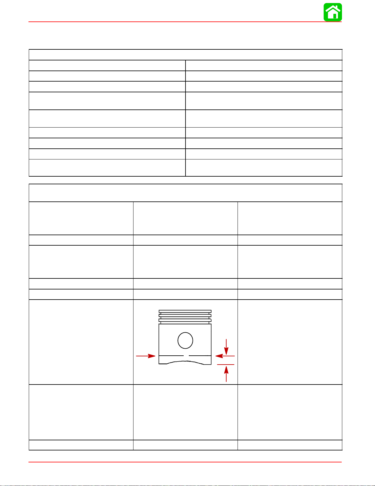
Piston Piston Type Aluminum
Piston Diameter
2.5578 ± .0004 in.
(64.97 ± 0.010 mm)
Dimension “A”
at Right
Angle
(90
°) to
Piston Pin
0.500 in.
Piston Ring End Gap
Top Ring
0.0059 - 0.0098 in.
(0.15 - 0.25 mm)
Middle Ring
0.0059 - 0.0098 in.
(0.15 - 0.25 mm)
Bottom Ring
0.0039 - 0.014 in.
(0.10 - 0.35 mm)
Reeds Reed Stand Open 0.010 in. (0.25 mm)
Page 3B-2
90-888438 JUNE 2002
Page 3
Special Tools
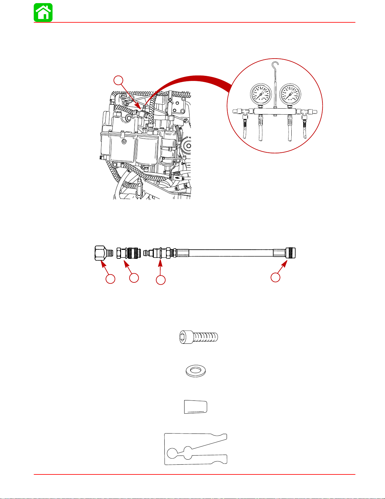
1. Duel Fuel/Air Pressure Gauge 160 psi – 91-852087A1/A2/A3
DIRECT FUEL INJECTION
a
57818
a-Schrader Valve “Tee” (22-849606)
2. Adaptors to convert pressure gauge 91-852087A1/A2 to an A23
NOTE: 2 Adaptors 91-803804A2 are required to convert a pressure gauge set.
a
b
c
d
a-1/2 in. to 1/4 in. Adapter (if required)
b-Female Quick Disconnect
c-Male Quick Disconnect
d-Screw on Schrader
3. Screw (5 mm x 25 mm) (2 each) – 10-40073-25
4. Flat Washer (2 each) – 12-30164
5. Seal/Teflon Ring Installation Tool – 91-851980
90-888438 JUNE 2002
56015
6. Seal/Teflon Ring Sizing Tool – 91-851980-1
56014
Page 3B-3
Page 4
DIRECT FUEL INJECTION
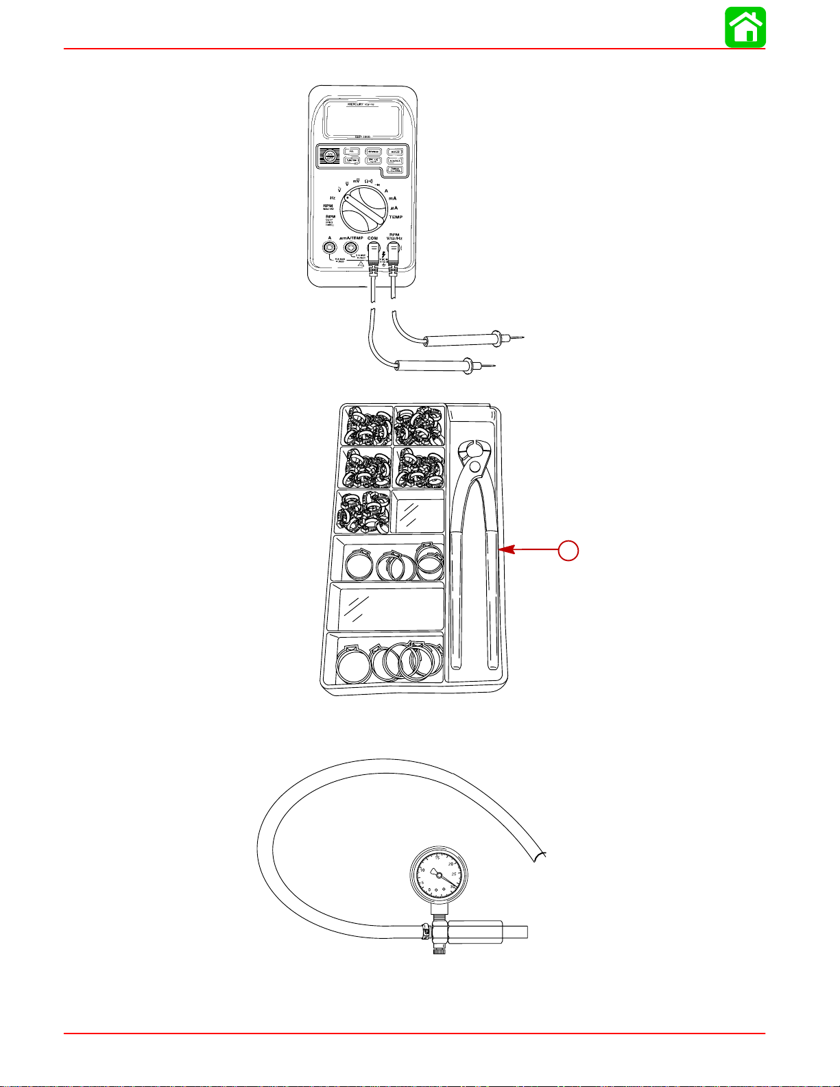
7. DMT 2000 Digital Tachometer Multi-meter P/N 91-854009A1
8. Clamp Tool Kit 91-803146A2
a-Clamp Tool 91-803146T
9. Gearcase Leakage Tester (FT-8950)
a
57316
57714
Page 3B-4
90-888438 JUNE 2002
Page 5

Notes:
DIRECT FUEL INJECTION
90-888438 JUNE 2002
Page 3B-5
Page 6
DIRECT FUEL INJECTION
Air Handler
Page 3B-6
25
25
Liquid Neoprene
90-888438 JUNE 2002
Page 7
DIRECT FUEL INJECTION
REF
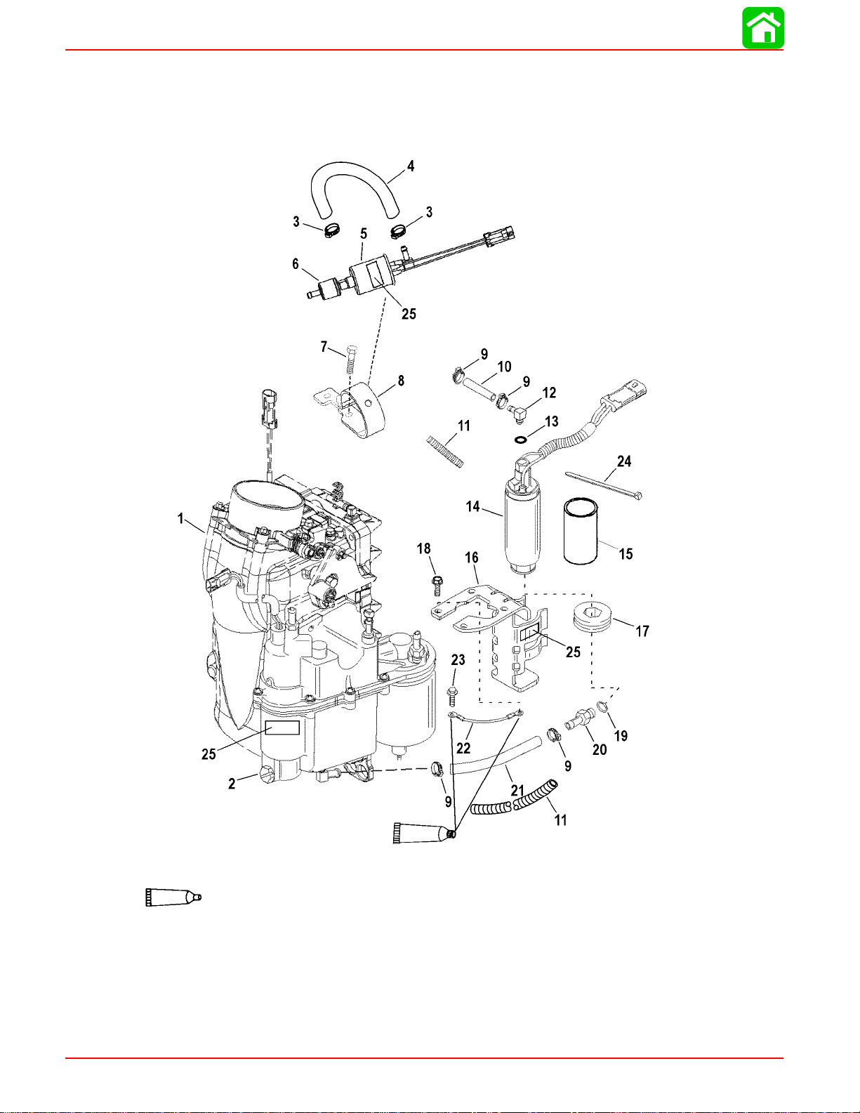
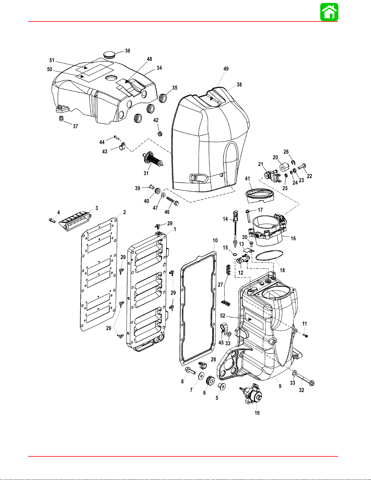
Air Handler
.
QTY. DESCRIPTION lb-in lb-ft Nm.
NO.
1 1 AIR HANDLER ASSEMBLY
2 1 VAPOR SEPARATOR ASSEMBLY
3 2 CLAMP (18.3)
4 AR HOSE (22 IN. Bulk)
5 1 FUEL PUMP ASSEMBLY
6 1 FILTER-Fuel Pump
7 1 SCREW (M6 x 35) 100 11.3
8 1 BRACKET-Fuel Pump Mount
9 4 CLAMP (18.3)
10 1 HOSE
11 AR INSULATING SLEEVE
12 1 ELBOW
13 1 O RING
14 1 FUEL PUMP ASSEMBLY
15 1 SLEEVE-Gray
16 1 BRACKET KIT
17 1 GROMMET
18 3 SCREW (M6 x 16) 100 11.3
19 1 O RING
20 1 FITTING 45 5.1
21 1 HOSE
22 1 WIRE ASSEMBLY-Ground
23 1 SCREW (M6 x 10) 40 4.5
24 1 CABLE TIE (14 IN.)
25 3 DECAL-Info
TORQUE
NOTE: THE EPA LABEL HAS IMPORTANT INFORMATION ON EPA EMISSION REGULATIONS. REPLACE ANY
MISSING OR UNREADABLE EPA LABEL.
90-888438 JUNE 2002
Page 3B-7
Page 8
DIRECT FUEL INJECTION
Air Handler Components
Page 3B-8
90-888438 JUNE 2002
Page 9
DIRECT FUEL INJECTION
REF
Air Handler Components
.
QTY. DESCRIPTION lb-in lb-ft Nm.
NO.
– 1 AIR HANDLER
1 1 ADAPTOR PLATE
2 1 GASKET
3 6 REED BLOCK
4 12 SCREW (M6 x 1) 90 10.2
5 3 BUSHING
6 3 GROMMET
7 3 WASHER
8 3 SCREW (M8 x 30) 150 17
9 1 AIR PLENUM KIT
10 1 GASKET
11 2 SCREW (M4 x 16) 22 2.5
12 1 SENSOR–MAP
13 1 BRACKET
14 1 TEMPERATURE SENSOR
15 1 O RING
16 1 THROTTLE BODY KIT
17 4 SCREW (M6 x 40) 65 7.3
18 1 O RING
19 1 OIL PUMP
20 1 ROLLER
21 1 THROTTLE ROLLER
22 1 SCREW 22 2.5
23 1 WASHER-Cupped
24 1 WASHER-Spool
25 1 LOCKWASHER (#10 External)
26 1 RETAINING RING
27 2 RETAINER-Hose Support
28 1 CLAMP
29 6 CHECK VALVE 40 4.5
30 1 SCREW (M6 x 16) 38 4.3
31 1 FILTER ASSEMBLY-Air
32 12 SCREW (M6 x 40) 120 13.6
33 2 WASHER
34 1 COVER ASSEMBLY-Flywheel
35 3 GROMMET
36 1 PLUG
37 2 GROMMET
38 1 ATTENUATOR ASSEMBLY-Air
39 1 BUSHING
40 1 GROMMET
TORQUE
90-888438 JUNE 2002
Page 3B-9
Page 10

DIRECT FUEL INJECTION
Air Handler Components
Page 3B-10
90-888438 JUNE 2002
Page 11
DIRECT FUEL INJECTION
REF
Air Handler Components
.
QTY. DESCRIPTION lb-in lb-ft Nm.
NO.
41 1 SEAL
42 1 GROMMET
43 1 CLIP
44 1 SCREW (#10-16 X .750)
45 1 CLAMP
46 1 SCREW (M6 X 25) 90 10.2
47 1 WASHER
48 1 DECAL-Logo (M2 Jet Drive)
49 1 DECAL-Logo (3.0l V6)
50 1 DECAL-Logo (Mercury Optimax 250)
51 1 DECAL-EPA Label Info
TORQUE
90-888438 JUNE 2002
Page 3B-11
Page 12
DIRECT FUEL INJECTION
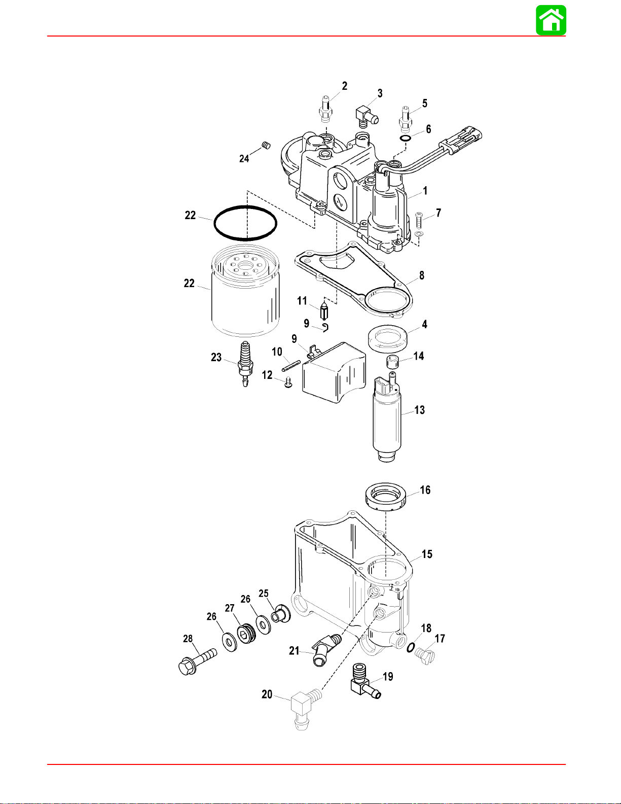
Vapor Separator Components
Page 3B-12
90-888438 JUNE 2002
Page 13
DIRECT FUEL INJECTION
REF
Vapor Separator Components
.
QTY. DESCRIPTION lb. in. lb. ft. N·m
NO.
1 1 COVER KIT
2 1 FITTING-Straight 65 7.3
3 1 FITTING-Elbow 50 5.7
4 1 SEAL
5 1 FITTING KIT-Pump Outlet 75 8.5
6 1 O RING
7 7 SCREW (#8-32 x .750) 22 2.5
8 1 GASKET
9 1 FLOAT KIT
10 1 SHAFT-Float
11 1 NEEDLE VALVE
12 1 SCREW (#6-32 x .187) 10 1.0
13 1 FUEL PUMP ASSEMBLY
14 1 SLEEVE
15 1 BOWL KIT
16 1 SEAL
17 1 PLUG KIT
18 1 O-RING
19 1 FITTING-Elbow 65 7.3
20 1 FITTING-Elbow 65 7.3
21 1 FITTING-Elbow 65 7.3
22 1 FUEL FILTER KIT
23 1 PROBE-Water Sensing 22 2.5
24 1 PLUG (.125-27)
25 3 BUSHING
26 6 WASHER
27 3 GROMMET
28 3 SCREW (M8 X 35)
TORQUE
90-888438 JUNE 2002
Page 3B-13
Page 14
DIRECT FUEL INJECTION
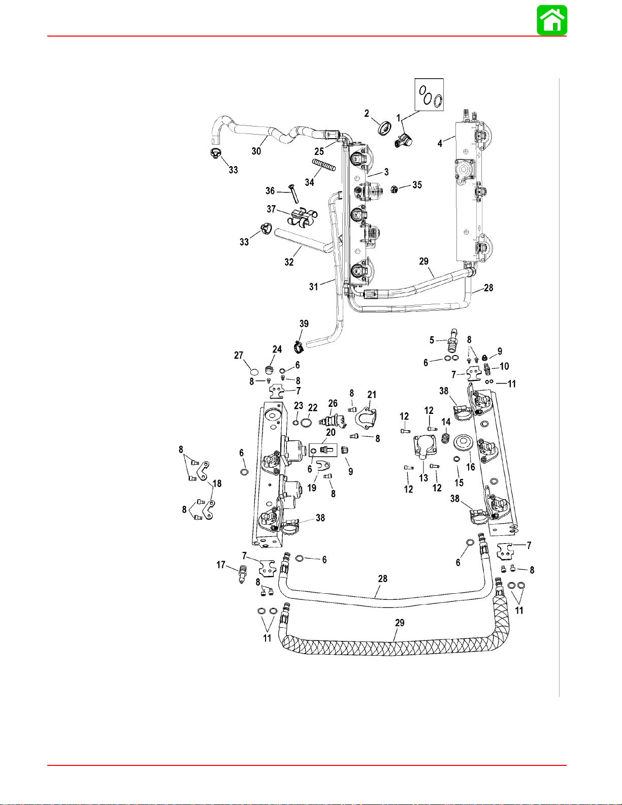
Fuel Rails
Page 3B-14
90-888438 JUNE 2002
Page 15
DIRECT FUEL INJECTION
REF
Fuel Rails
.
QTY. DESCRIPTION lb-in lb-ft Nm.
NO.
1 6 AIR INJECTOR KIT
2 6 WASHER ASSEMBLY-Cupped
3 1 FUEL RAIL (PORT)
4 1 FUEL RAIL (STARBOARD)
5 1 FITTING
6 1 O-RING KIT
7 4 CLAMP
8 15 SCREW (M5 x 8) 70 8
9 2 CAP
10 1 FUEL VALVE KIT
11 1 O-RING KIT
12 4 SCREW (M5 x 16) 70 8
13 1 COVER
14 1 SPRING
15 1 O-RING
16 1 DIAPHRAGM
17 1 FITTING
18 2 CLAMP
19 1 CLAMP
20 1 AIR VALVE ASSEMBLY
21 4 CLAMP
22 1 O-RING KIT
23 1 O-RING KIT
24 1 AIR PLUG
25 1 ELBOW
26 6 FUEL INJECTOR
27 1 SEAL
28 1 HOSE ASSEMBLY-Air Balance
29 1 HOSE ASSEMBLY-Fuel Balance
30 1 HOSE ASSEMBLY-Fuel Supply
31 1 HOSE ASSEMBLY-Air By Pass
32 1 HOSE ASSEMBLY-Fuel By Pass
33 2 CLAMP (18.3)
34 4 STUD (M10 x 91)
35 4 NUT (M10)
36 1 SCREW (M5 x 35)
37 1 CLAMP-Hose Support
38 4 CLIP-Conduit Support
39 1 CLAMP-Worm Gear
TORQUE
90-888438 JUNE 2002
Page 3B-15
Page 16
DIRECT FUEL INJECTION
Air Compressor Components
Page 3B-16
7
Loctite 271
90-888438 JUNE 2002
Page 17
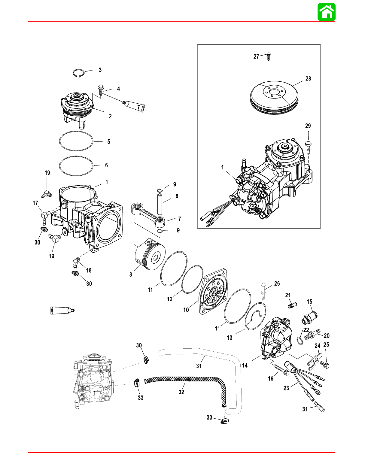
DIRECT FUEL INJECTION
REF
Air Compressor Components
.
QTY. DESCRIPTION lb-in lb-ft Nm.
NO.
1 1 AIR COMPRESSOR
2 1 END CAP
3 1 RING-Retaining
4 4 SCREW (M6 X 20) 100 11.3
5 1 O RING
6 1 O RING
7 1 CONNECTING ROD
8 1 PISTON ASSEMBLY
9 2 LOCK RING
10 1 REED PLATE ASSEMBLY
11 2 O RING
12 1 O RING
13 1 SEAL
14 1 COMPRESSOR HEAD KIT
15 1 FITTING 25 33.9
16 4 SCREW (M8 x 35) See Note
17 1 ELBOW
18 1 ELBOW
19 2 CHECK VALVE
20 1 FITTING 25 33.9
21 1 FITTING
22 1 O RING
23 1 TEMPERATURE SENSOR
24 1 RETAINER
25 1 SCREW (M8 x 14) 150 17
26 1 PIN 45 5.1
27 6 SCREW (M6 x 12) 14-15 19-
28 1 PULLEY
29 4 SCREW (M8 x 50) 20 27.1
30 4 CABLE TIE (8 IN.)
31 1 HOSE
32 1 HOSE ASSEMBLY
33 2 CLAMP (15.3)
TORQUE
20.3
NOTE: Item #16 - Torque screws to 27.1 Nm (240 lb-in.), plus 90 degree turn
90-888438 JUNE 2002
Page 3B-17
Page 18

DIRECT FUEL INJECTION
DFI Operation
Air Induction Through Crankcase
Once inside the enclosure the air enters the plenum through the throttle shutter which is
located in the plenum assembly . The air then continues through the reed valves and into
the crankcase. The throttle shutter is actuated by the throttle shaft. Mounted on a separate
shaft is a throttle position sensor (TPS). This sensor tells the engine control unit (ECM)
the position of the throttle.
If the TPS should fail, the warning horn will sound. Engine speed will be reduced.
Air Compressor System
Air from inside the engine enclosure is drawn into the compressor through the air attenuator. This attenuator acts like a muffler to quiet compressor noise and contains a filter to
prevent the ingestion of debris into the compressor. The compressor is driven by a belt
from a pulley mounted on the flywheel and is automatically self adjusted using a single
idler pulley . This air compressor is a single cylinder unit containing a connecting rod, piston, rings, bearings, reed valves, and a crankshaft. The compressor is water cooled to
lower the temperature of the air charge and is lubricated by oil from the engine oil pump
assembly. As the compressor piston moves downward inside the cylinder, air is pulled
through the filter, reed valves and into the cylinder. After the compressor piston changes
direction, the intake reeds close and the exhaust reeds open allowing compressed air into
the hose leading to the air/fuel rails.
Fuel
The air/fuel rails contain two passages; one for fuel, the second is the air passage. The
air passage is common between all the cylinders included in the rail. A hose connects the
starboard rail air passage to the air compressor . Another hose connects the starboard air
rail passage to the port air rail passage. An air pressure regulator will limit the amount of
pressure developed inside the air passages to approximately 10 psi below the pressure
of the fuel inside the fuel passages (i.e. 80 psi air vs 90 psi fuel). Air exiting the pressure
regulator is discharged through the adaptor plate.
Fuel for the engine is stored in a typical fuel tank. A fuel lift pump draws fuel through the
fuel line and fuel filter, then pushes the fuel through a water separating fuel filter. This filter
removes any contaminates and water before the fuel reaches the vapor separator. Fuel
vapors are vented through a hose to the fuel tank. The electric fuel pump in the VST is
different than the fuel pump that is utilized on the standard EFI engine (non DFI), and is
capable of developing fuel pressures in excess of 90 psi. Fuel inside the rail must remain
pressurized at exactly 10 psi over the air rail pressure or the ECM (map) calibrations will
be incorrect. Fuel from the vapor separator is supplied to the top of the port fuel rail. A fuel
line connects the bottom of the first rail to the opposite fuel rail. Fuel is stored inside the
rail until an injector opens. A fuel pressure regulator controls pressure in the fuel rails, and
allows excess fuel to return into the vapor separator . The fuel regulator not only regulates
fuel pressure but also regulates it at approximately 10 p.s.i. higher than whatever the air
rail pressure is. The fuel regulator diaphragm is held closed with a spring that requires 10
p.s.i. to force the diaphragm off the diaphragm seat. The back side of the diaphragm is
exposed to air rail pressure. As the air rail pressure increases, the fuel pressure needed
to open the regulator will equally increase. Example: If there is 50 p.s.i. of air pressure on
the air rail side of the diaphragm, 60 p.s.i. of fuel pressure will be required to open the
regulator. The port fuel rail is water cooled.
Page 3B-18
90-888438 JUNE 2002
Page 19

Oil
Electrical
DIRECT FUEL INJECTION
To equalize the pulses developed by the pumps (both air and fuel) a tracker diaphragm
is installed in the starboard rail. The tracker diaphragm is positioned between the fuel and
air passages. The tracker diaphragm is a rubber diaphragm which expands and retracts
depending upon which side of the diaphragm senses the pressure increase (pulse).
Oil in this engine is not mixed with the fuel before entering the combustion chamber. Oil
is stored inside a standard remote oil reservoir. Crankcase pressure will force oil from the
remote oil tank into the oil reservoir on the side of the powerhead. Oil will flow from the
oil reservoir into the oil pump. The oil pump is a solenoid design. It is activated by the ECM
and includes 7 pistons with corresponding discharge ports. The oil pump is mounted directly onto the powerhead. Each cylinder is lubricated by one of the discharge ports. The
oil is discharged into the crankcase. Bleed hoses carry excess oil from the crankcase to
the transfer ports. The seventh passage connects to the hose that leads to the air compressor for lubrication. Excess oil from the compressor provides lubrication for the upper
and lower crank bearing.
The ECM will change the discharge rate of the oil pump, depending upon engine demand.
The ECM will also pulse the pump on initial start up to fill the oil passages eliminating the
need to bleed the oil system. The ECM provides additional oil for break in, as determined
by its internal clock. The oil ratio varies with engine rpm and load.
Operation
The electrical system consists of the ECM, crank position sensor (flywheel speed & crankshaft position), throttle position sensor (TPS), MAP sensor, engine temperature sensor,
ignition coils and injectors (fuel & direct). The engine requires a battery to start (i.e. the
ignition and injection will not occur if the battery is dead). The system will run off of the
alternator.
The operation of the system happens in milliseconds (ms); exact timing is critical for engine performance. As the crankshaft rotates, air is drawn into the crankcase through the
throttle shutter, into the plenum and through the reed valves. As the piston nears bottomdead-center, air from the crankcase is forced through the transfer system into the cylinder.
As the crankshaft continues to rotate the exhaust and intake ports close. With these ports
closed, fuel can be injected into the cylinder. The ECM will receive a signal from the
throttle position sensor (TPS), engine temperature sensor (TS) and the crank position
sensor (flywheel speed and position sensor). With this information the ECM refers to the
fuel calibration (maps) to determine when to activate (open and close) the injectors and
fire the ignition coils. With the piston in the correct position, the ECM opens the fuel injector, 90 psi fuel is discharged into a machined cavity inside the air chamber of the air/fuel
rail. This mixes the fuel with the air charge. Next the direct injector will open, discharging
the air/fuel mixture into the combustion chamber. The direct injector directs the mixture
at the bowl located in top of the piston. The piston’s bowl directs the air/fuel mixture into
the center of the combustion chamber. This air fuel mixture is then ignited by the spark
plug.
90-888438 JUNE 2002
Compressor Notes: To aid in starting when the air rail pressure is low and before the
compressor has time to build pressure, some direct injectors are held open by the ECM.
This allows the compression from inside the cylinders to pressurize the air rail faster (1
°
or 2 strokes, or 60
of crankshaft rotation).
Page 3B-19
Page 20

DIRECT FUEL INJECTION
Testing Electric Fuel Pump Pressure Output
Low Pressure Electric Fuel Pump
IMPORT ANT: Af t e r completing fuel pressure tests, reconnect and secure fuel outlet
hose to fuel pump with full circle stainless clamps in Clamp Tool Kit 91-803146A1.
1. Remove outlet fuel hose from low pressure pump. Install a short piece of hose (obtain
locally) onto pump outlet fitting. Install Schrader Valve t-fitting (22-849606) between
outlet fuel hose (removed from pump) and new fuel hose (installed on pump). Secure
hose connections with sta-straps. Due to the low pressure output of this pump, it is
recommended that the air gauge of the Dual Fuel/Air Pressure Gauge
(91-852087A1/A2/A3) be connected to the Schrader Valve. Gauge should indicate
6-9 psi (41.37 - 62.04 kPa).
a
c
b
d
57818
a-Outlet Fuel Hose
b-Low Pressure Electric Fuel Pump
c-Fuel Hose (obtain locally)
d-Schrader Valve (22-849606)
57416
Page 3B-20
90-888438 JUNE 2002
Page 21

High Pressure Electric Fuel Pump
1. Install Pressure Gauge Assembly (91-852087A1/A2/A3) to starboard fuel rail pressure test valve.
NOTE: If low air or low fuel pressure is indicated, swap hoses between air and fuel test
ports. If low reading moves, gauge accuracy should be checked.
NOTE: After 15 seconds of cranking engine with starter motor, fuel pressure gauge
±
should indicate 90
2 psi (620.5 ±13.8 kPa).
DIRECT FUEL INJECTION
a
b
00149
a-Fuel Pressure Gauge [Should Indicate 90 ± 2 psi (620.5 ± 13.8 kPa)]
b-Fuel Pressure Test Valve
90-888438 JUNE 2002
Page 3B-21
Page 22

DIRECT FUEL INJECTION
Fuel Management Assembly Removal
CAUTION
Fuel system must be bled off prior to removal of fuel system components.
WARNING
Drain fuel from vapor separator tank (VST) into a suitable container. Even though
VST has been drained, fuel may still remain in fuel rails and hoses. Normal precautionary procedures should be adhered to while working with the fuel system.
Avoid sparks, smoking and open flame while in the presence of liquid fuel or fuel
vapors.
NOTE: Use Fuel/Air Pressure Gauge 91-16850--1 or 91-852087A1/A2/A3 to de-pressur-
ize air hose first and then fuel hose.
1. Remove flywheel cover.
2. Remove air attenuator mounting screw and air attenuator.
3. De-pressurize fuel system.
b
a
d
c
00150
a-Port fuel rail
b-Air pressure test valve
4. Place suitable container underneath vapor separator drain plug and remove plug.
5. Disconnect water separator sensor lead.
6. Disconnect electric fuel pump harness connectors.
c-Fuel pressure test valve
d-Starboard fuel rail
Page 3B-22
a-Drain Plug
b-Sensor Lead
c
a
b
c-Harness Connectors
90-888438 JUNE 2002
Page 23

DIRECT FUEL INJECTION
NOTE: Lower fuel hose is excess fuel return from fuel rails. Upper fuel hose is fuel inlet
from electric circulating pump beside fuel/water separator.
7. Remove vapor separator vent hose.
8. Remove the fuel outlet hose and fuel return hose from fuel rails.
9. Remove vapor separator ground lead.
10. Remove 3 mounting bolts and remove separator.
c
d
59409
e
b
a
e
a-Fuel Inlet Hose to Fuel
Lift Pump
b-Vapor Separator Vent
Hose
c-Fuel Hose Low Pres-
sure Pump to High
Pressure Pump
d-Fuel Rail Return Hose
e-Mounting Bolts (3)
90-888438 JUNE 2002
Page 3B-23
Page 24

DIRECT FUEL INJECTION
11. Disconnect throttle cam link rod and the Throttle Position Sensor link rod.
12. Disconnect MAP sensor and temperature sensor from air management assembly.
c
b
a
d
a-Throttle Cam Link Rod
b-Throttle Position Sensor Link Rod
c-MAP Sensor
d-Temperature Sensor
13. Disconnect oil outlet hoses from oil pump.
14. Remove and plug oil inlet hose to oil pump.
15. Remove 12 bolts securing air management assembly to crankcase and remove assembly.
b
Page 3B-24
a
a-Oil Outlet Hoses
b-Oil Inlet Hose
c-Air Plenum
d-Bolts (12 each)
d
c
59409
90-888438 JUNE 2002
Page 25

Reed Block Assembly Removal
1. Remove 12 screws securing air plenum to crankcase cover.
a-Screws (12 each) M6x40
Reed Block Assembly Installation
1. Secure oil pump to air plenum with 3 bolts. Torque bolts to 140 lb. in. (16 Nm).
DIRECT FUEL INJECTION
a
2. Secure air plenum/reed block assembly to crankcase cover with 12 screws. Torque
screws in appropriate torque sequence to 120 lb.in. (13.5 Nm).
10
6
2
3
7
9
5
1
4
8
a
90-888438 JUNE 2002
a-Oil Pump
11
12
57997
Page 3B-25
Page 26

DIRECT FUEL INJECTION
Air Temperature Sensor Removal
Disconnect sensor harness and unscrew sensor.
a
b
a-Air Temperature Sensor Harness Connector
b-Air Temperature Sensor
Air Temperature Sensor Installation
Screw sensor into air plenum. Reconnect sensor harness.
Throttle Plate Assembly Removal
NOTE: The throttle plate assembly is calibrated and preset for proper running character-
istics and emissions at the factory. Other than complete assembly removal from the air
plenum, no further disassembly should be made.
Remove 4 bolts securing throttle plate assembly to air plenum and remove assembly.
b
57793
a
a-Bolts
b-Throttle Plate Assembly
Throttle Plate Assembly Installation
Secure throttle plate assembly to air plenum with 4 bolts. Torque bolts to 65 lb. in. (7.3
Nm).
Page 3B-26
a
57793
90-888438 JUNE 2002
Page 27

Vapor Separator Disassembly
1. Remove 7 screws securing separator cover and remove cover.
2. Inspect seal in fuel pump chamber of separator tank for cuts and abraisions. Replace
seal if necessary. If seal is serviceable, apply 2-4-C with Teflon to seal lips.
DIRECT FUEL INJECTION
a
a
a
a
b
a
a
3. Fuel pump may be removed from cover by wiggling slightly while pulling outward.
IMPORTANT: DO NOT twist pump during removal as wire harness may be damaged.
4. Disconnect harness from pump to separate pump from cover. Inspect filter screen for
debris. Screen may be pried out of pump and cleaned as required.
5. Inspect seal above fuel pump for cuts or abraisions. Replace seal if necessary. Apply
2-4-C with Teflon to seal lips.
a
a-Screws (7 each)
b-Seal
57955
57342
b
b
a-Filter Screen
b-Harness Connector
c-Pump
d-Seal (Seal shoulder faces OUT)
c
c
a
56057
d
56058
90-888438 JUNE 2002
Page 3B-27
Page 28

DIRECT FUEL INJECTION
b
b
6. Loosen screw securing float assembly and remove float. Inspect float for deterioration
or fuel retention. Replace float as required.
7. Remove phenolic sealing plate and inspect imbedded neoprene seal on both sides
of plate for cuts or abraisions. Replace plate/seal assembly as required.
a
c
d
a
a
56059
56058
a-Screw
b-Float
c-Plate
d-Seal
Page 3B-28
90-888438 JUNE 2002
Page 29

Vapor Separator Reassembly
1. Reinstall phenolic sealing plate onto vapor separator cover.
2. Secure float, needle and pivot pin assembly to separator cover with screw. Torque
screw to 10 lb. in. (1.0 Nm).
3. Apply 2-4-C with Teflon to lips of seal in separator cover.
4. Connect electrical harness to fuel pump. Inspect fuel pump filter screen for debris. Remove screen and clean as required.
5. Seat fuel pump and harness into separator cover being careful not to pinch harness.
a
a
f
b
b
e
e
a-Sealing Plate
b-Float
c-Needle
d-Pivot Pin
e-Screw [Torque to 10 lb. in.
(1.0 N·m)
DIRECT FUEL INJECTION
c
c
d
d
g
56058
a
c
i
f-Seal (Seal shoulder faces OUT)
g-Harness
h-Filter
i-Fuel Pump
h
56057
6. Apply 2-4-C with Teflon to lips of seal in separator tank.
7. Install separator cover with pump onto separator tank.
8. Secure cover to tank with 7 screws. Torque screws to 30 lb. in. (3.5 Nm).
a
b
b
b
b
b
b
b
57342
a-Seal
b-Screws [Torque to 30 lb. in. (3.5 Nm)]
90-888438 JUNE 2002
Page 3B-29
Page 30

DIRECT FUEL INJECTION
Air Plenum Installation
Secure plenum to crankcase with 12 bolts. Torque bolts to 100 lb. in. (11.5 Nm). in sequence shown.
b
10
a
6
2
3
7
11
a-Air Plenum
b-Bolts [Torque to 100 lb. in. (11.5 Nm)]
Low Pressure Electric Fuel Pump Installation
NOTE: If pump does not have a sleeve or grommet, refer to Service Bulletin 98-8.
9
5
1
4
8
12
57915
1. Seat electric fuel pump with sleeve against grommet in pump bracket. Secure pump
to bracket with sta-strap.
a
d
b
c
a-Low Pressure Electric
Fuel Pump
b-Sleeve
c-Grommet
d-Bracket
Page 3B-30
90-888438 JUNE 2002
Page 31

DIRECT FUEL INJECTION
2. Secure bracket assembly to vapor separator with 2 screws. Torque screws to 100 lb.
in. (11.5 Nm).
c
a
a
b
57964
a-Screws – Torque to 100 lb. in. (11.5 Nm)
b-Sta-strap securing pump to bracket
c-Ground lead – attach to air plenum
IMPORTANT: Only use tool 91-803146T (or Snap-On equivalent YA3080) to crimp
full circle clamps. Using a different tool could result in a crimp that is too loose, or
too tight. Do not use screw type metal hose clamp as it may damage hose.
90-888438 JUNE 2002
3. Connect fuel hose from bottom of low pressure fuel pump to 90° elbow in bottom of
vapor separator . Secure hose with 18.3 mm full circle clamp (54-880141) using crimping tool 91-803146T.
a
a
57965
a-Secure Fuel Hose with 18.3 mm Full Circle Clamp (54-880141)
Page 3B-31
Page 32

DIRECT FUEL INJECTION
4. Connect fuel hose from top of low pressure fuel pump to 90° elbow on back side of
vapor separator . Secure hose with 18.3 mm full circle clamp (54-880141) using crimping tool 91-803146T.
a
a
57966
a-Secure Fuel Hose with 18.3 mm Full Circle Clamp (54-880141)
Page 3B-32
90-888438 JUNE 2002
Page 33

Vapor Separator Installation
1. Secure vapor separator to air plenum with 3 bolts. Torque bolts to 140 lb. in. (16.0 Nm).
2. Connect fuel inlet hose to fuel lift pump.
3. Connect vent hose to vapor separator.
4. Connect fuel outlet hose and fuel return hose to vapor separator.
5. Connect water separator sensor lead to water separator.
6. Connect electric fuel pump harnesses.
h
DIRECT FUEL INJECTION
d
e
59409
a-Mounting Bolts [Torque
to 140 lb. in. (16.0 Nm)
b-Fuel Inlet Hose
c-Vent Hose
d-Fuel Outlet Hose (90
psi)
e-Fuel Return Hose from
rail
a
c
b
i
g
a
f
f-Water Separator Sensor Lead
g-Electrical Harness
h-Fuel Outlet from Low Pressure Pump
i-5 AMP. Fuse Electric Fuel Pump
90-888438 JUNE 2002
Page 3B-33
Page 34

DIRECT FUEL INJECTION
7. If fuel hoses were removed, secure hoses with proper full circle clamp using tool
91-803146T (or Snap-On equivalent Y A3080) to crimp clamps. Use stainless screw
clamp on vapor separator vent hose and inlet fuel hose to fuel lift pump.
a
a
a
b
59409
a-Full Circle Clamp
b-Stainless Screw Clamp
a
59415
Page 3B-34
90-888438 JUNE 2002
Page 35

Fuel Rail Removal
NOTE: To provide improved access to the fuel rails, it is recommended that the expansion
chamber be removed as follows:
1. Remove coolant hose between air compressor and expansion chamber, and rail and
expansion chamber.
2. Remove 6 nuts securing expansion chamber and lay chamber off to one side.
DIRECT FUEL INJECTION
a
a
b
b
59414
a
59412
a-Coolant Hose b-Nuts (6)
CAUTION
Fuel system must be bled off prior to removal of fuel system components.
NOTE: Use Fuel/Air Pressure Gauge 91-16850--1 or 91-852087A1/A2 to de-pressurize
air hose first and then fuel hose.
1. De-pressurize fuel system.
2. Remove fuel injector harness from each injector by compressing spring clip with flat
tip screw driver while pulling on connector.
a
e
c
d
90-888438 JUNE 2002
b
a-Fuel Pressure Port
b-Air Pressure Port
c-Fuel Injector
d-Harness Connector
e-Spring Clip
NOTE: Always remove fuel/air hose and fitting together by removing fitting retainer rather
cutting clamps.
00151
Page 3B-35
Page 36

DIRECT FUEL INJECTION
3. Remove fuel, water and air hoses from fuel rail.
d
a
c
f
e
b
00136
Port Top Fuel Rail Connections Starboard Top Fuel Rail Connections
a-Water Inlet Hose to Compressor
b-Retainer
c-Allen Screws (remove)
c
d-Air Hose
e-Retainer
f-Allen Screws (remove)
f
00137
g
d
00138
a
b
e
00139
Port Bottom Fuel Rail Connections Starboard Bottom Fuel Rail Connections
a-Water Inlet Hose to Fuel Rail
b-Air Hose
c-Allen Screws (remove)
e-Air Hose
f-Allen Screws
g-Fuel Hose
d-Fuel Hose
NOTE: It is recommended that direct injectors remain in the cylinder head (if they are not
to be replaced) while removing the fuel rail. The direct injectors have a teflon seal which
may expand if the injector is removed from the head. This expansion may cause reinstallation difficulty or require the replacement of the seal.
4. Remove 2 nuts securing fuel rail.
Page 3B-36
90-888438 JUNE 2002
Page 37

DIRECT FUEL INJECTION
5. As fuel rail is removed, use a flat tip screw driver to hold direct injectors in cylinder
head.
b
b
b
b
56121
a
a
a-Fuel Rail b-Direct Injectors
The starboard fuel rail contains 3 fuel injectors and a tracker valve.
The port fuel rail contains 3 fuel injectors, 1 fuel regulator, and 1 air regulator.
http://motorka.org
NOTE: Each fuel/air inlet or outlet hose adaptor has 2 o-ring seals. These o-rings should
be inspected for cuts or abraisions and replaced as required when fuel rail is disassembled for cleaning.
e
a
a
d
a
c
a
b
a
a
i
h
f
g
57971
j
a-Fuel Injector
b-Fuel Regulator
c-Air Regulator
d-Tracker Valve
e-Coolant Inlet to Expan-
sion Chamber
f-Return Fuel to VST
g-Water Inlet for Cooling
Fuel Rail
h-Excess Air to Adaptor
Plate
i-90 psi (616 kPa) Fuel
j-80 psi (547.8 kPa) Air
90-888438 JUNE 2002
Page 3B-37
Page 38

DIRECT FUEL INJECTION
FUEL INJECTOR REMOVAL
1. Remove 2 screws securing injector.
NOTE: Use a cotter pin extractor tool in pry holes to remove injectors.
2. Gently pry up on injector to loosen o-ring adhesion and remove injector.
b
a
57970
57967
a-Screws
b-Pry Holes
3. Inspect fuel injector orifices for foreign debris; o-rings for cuts or abraisions and plastic
components for heat damage. Replace components as required.
4. An ohm test of the fuel injector may be made by connecting test leads to injector terminals. Ohm reading should be 1.8 ± 0.1 ohm.
a
a
c
c
Page 3B-38
b
b
56124
a-Fuel Injector
b-Fuel Nozzle
c-O-Rings
56002
90-888438 JUNE 2002
Page 39

FUEL INJECTOR INSTALLATION
NOTE: Apply anti-seize grease (obtain locally) or 2-4-C with Teflon to fuel injector attach-
ing screw threads.
1. Insert fuel injector into fuel rail with connector pins facing (inwards) towards center of
engine.
NOTE: Turn injector back-and-forth slightly to seat injector o-rings in fuel rail while securing injector with retainer and 2 screws. Torque screws to 70 lb. in. (8.0 Nm).
DIRECT FUEL INJECTION
c
a
a-Injector
b-Retainer
c-Screws [Torque to 70 lb. in. (8.0 Nm)]
b
57970
90-888438 JUNE 2002
Page 3B-39
Page 40

DIRECT FUEL INJECTION
Fuel Pressure Regulator
The fuel regulator is located on the port fuel rail.
57980
The fuel pump is capable of delivering more fuel than the engine can consume. Excess
fuel flows through the fuel pressure regulator, interconnecting passages/hoses, fuel cooler, and back to the vapor separator tank. This constant flow of fuel means that the fuel
system is always supplied with cool fuel, thereby preventing the formation of fuel vapor
bubbles and minimizing the chances of vapor lock.
The fuel pressure regulator is calibrated to raise the fuel pressure to 10 psi above the air
pressure.
The fuel regulator is mounted on the port fuel rail, near the bottom. This regulator relies
on both air and spring pressure to control the fuel pressure. Inside the regulator assembly
is a 1 0 lb. spring, this spring holds the diaphragm against the diaphragm seat. The contact
between the diaphragm and diaphragm seat closes the passage between the incoming
fuel (from the electric fuel pump) and the fuel return passage.
When the engine is not running (no air pressure on the spring side of the diaphragm) the
fuel pressure required to move the diaphragm is 10 psi.
When the engine is running, air pressure from the air compressor (80 psi) is routed
through the air passages, to the spring side of the fuel pressure regulator diaphragm.
The air pressure (80 psi) and spring pressure (10 psi) combine to regulate system fuel
pressure to 90 psi - or 10 psi higher than the air pressure in the DFI system fuel/air rails.
Page 3B-40
90-888438 JUNE 2002
Page 41

DIRECT FUEL INJECTION
Regulator Closed Regulator Open
11
11
12
12
1
1
13
13
10
10
1
1
2
2
3
3
4
4
5
5
6
6
7
7
11
11
8
8
9
9
12
13
10
10
9
9
2
2
3
3
4
4
5
5
6
6
7
7
8
8
1-Top Cover
2-Expansion Plug
3-O-ring
4-Spring Retainer
5-Spring
6-O-ring
7-Diaphragm Seat
8-Air Rail
9-Air Passage (from Air Compressor)
10 - Fuel Return Passage (to Vapor Separator)
11 - Fuel Inlet Passage (from Electric Fuel Pump)
12 - Diaphragm Assembly
13 - Calibration Screw (Do Not Turn)
90-888438 JUNE 2002
Page 3B-41
Page 42

DIRECT FUEL INJECTION
FUEL REGULATOR REMOVAL
1. Remove 4 screws securing regulator and remove regulator.
2. Inspect regulator diaphragm for cuts or tears.
3. Inspect regulator housing o-ring for cuts and abraisions. Replace components as required.
a
b
a-Screws
b-Fuel Regulator
c-Diaphragm
FUEL REGULATOR INSTALLATION
NOTE: Apply a light coat of 2-4-C with Teflon to diaphragm surface and o-ring to aid in
the retention of diaphragm and o-ring on fuel rail during reassembly.
1. Position diaphragm on fuel rail.
2. Position o-ring on fuel rail.
3. Position spring and cup onto diaphragm.
NOTE: Apply anti-seize grease (obtain locally) or 2-4-C with Teflon to regulator attaching
screw threads.
e
d
f
c
a
57968 57969
d-Spring
e-Cup
f-O-Ring
4. Place cover over spring/cup/diaphragm assembly and secure with 4 screws. Torque
screws to 70 lb. in. (8.0 Nm).
a
b
e
c
d
57975
a-Diaphragm
b-O-Ring
c-Spring
d-Cup
e-Screws [Torque to 70 lb. in. (8.0 Nm)]
e
57968
Page 3B-42
90-888438 JUNE 2002
Page 43

Air Pressure Regulator
The air pressure regulator is located on the port fuel rail.
The air pressure regulator is designed to limit the air pressure inside the rails to approximately 80 psi.
DIRECT FUEL INJECTION
57980
The air regulator uses a spring (pressure) to control the air pressure. This spring (80 psi)
holds the diaphragm against the diaphragm seat. The contact area blocks (closes) the
air inlet passage from the excess air, return passage. As the air pressure rises (below the
diaphragm), it must reach a pressure equal to or greater than the spring pressure holding
the diaphragm closed. Once this pressure is achieved, the spring compresses, allowing
the diaphragm to move. The diaphragm moves away from the diaphragm seat, allowing
air to exit through the diaphragm seat, into the excess air passage leading to the air plenum.
Air Regulator Troubleshooting
Air pressure should be measured at the air schrader valve located near the middle of the
port fuel rail assembly.
Is air pressure within 78 to 82 psi range at neutral idle psoition?
No
Less than 78 psi? Greater than 82 psi?
Remove air regulator and clamp.
Inspect air regulator o-ring.
Air regulator o-ring OK and
air pressure is less than 78 psi?
Remove air bypass hose from
exhaust adaptor and measure
air pressure at neutral idle condition.
Air pressure normal – 78 to 82 psi?
Yes
Air regulator is OK
Air pressure greater
than 82 psi?
Air exiting air bypass?
Yes?
Failed air regulator.
90-888438 JUNE 2002
No?
Plugged bypass circuit in adaptor plate.
Obstruction at compressor inlet
or outlet or failed compressor
Failed air regulator.
Page 3B-43
Page 44

DIRECT FUEL INJECTION
Regulator Closed Regulator Open
1 2
1
1
2
1
2
2
10
10
12
12
11
11
3
3
4
4
5
5
6
6
10
10
7
7
9
9
8
8
12
12
11
11
9
9
8
8
3
3
4
4
5
5
6
6
7
7
1-Top Cover
2-Expansion Plug
3-Spring Retainer
4-Vent
5-Spring
6-Diaphragm Seat
7-Air Rail
8-Air Passage (from Air Compressor)
9-Excess Air Passage (to Exhaust Adaptor)
10 - Fuel Inlet Passage (from Electric Fuel Pump)
11 - Diaphragm Assembly
12 - Calibration Screw (Do Not Turn)
Page 3B-44
90-888438 JUNE 2002
Page 45

AIR REGULATOR REMOVAL
1. Remove 4 screws securing regulator and remove regulator.
2. Inspect regulator diaphragm for cuts or tears. Replace as required.
b
DIRECT FUEL INJECTION
c
a a
a-Screws
b-Air Regulator
c-Diaphragm
AIR REGULATOR INSTALLATION
NOTE: Apply a light coat of 2-4-C with Teflon to diaphragm surface to aid in the retention
of diaphragm on fuel rail during reassembly.
1. Position diaphragm, spring and cup onto fuel rail with fuel rail in horizontal position.
NOTE: Apply anti-seize grease (obtain locally) or 2-4-C with Teflon to regulator attaching
screw threads.
NOTE: Due to the stiffness of the regulator spring, it is recommended that 2 longer screws
(5mm x 25mm long) (10-40073 25) and 2 flat washers (12-30164) be installed through
cover first to begin compression. This will allow 2 shorter screws (5mm x 15mm long) to
be installed. Remove 2 long screws with flat washers and install remaining 2 short screws
(5mm x 15mm). Torque screws to 70 lb. in. (8.0 Nm).
57968
d
e
57974
d-Spring
e-Cup
a
c
c
90-888438 JUNE 2002
a-Cup
b-Spring
c-Diaphragm
d
e
f
e
f
b
57973
d-Cover
e-Screws
f-Flat Washers
Page 3B-45
Page 46

DIRECT FUEL INJECTION
Tracker Valve
The tracker valve is located on the starboard fuel/air rail assembly.
57979
The DFI system must maintain a constant 10 psi pressure difference between the fuel
pressure and air pressure in the rails, at all times. The tracker is designed to maintain the
10 psi differential when the air or fuel pressure suddenly raises (i.e. pulses generated by
the compressor’s piston or by the fuel injectors opening and closing). The tracker contains
a spring on the air side of the diaphragm. This spring positions the diaphragm against the
diaphragm’s seat (when the engine is not running).
After the engine starts, and the fuel and air pressure reach normal operating range, the
fuel pressure will compress the spring and the diaphragm will move slightly away from the
seat (to a neutral position). At this point the pressure on both sides of the tracker diaphragm is equal (10 psi spring pressure + 80 psi air pressure = 90 psi fuel pressure).
Any air or fuel pressure “spikes” on one side of the diaphragm will transfer this pressure
rise to the other system (air or fuel) on the other side of the diaphragm. Both systems will
have a momentary increase in pressure so that the 10 psi difference between air and fuel
system pressures can be maintained.
NOTE: To prevent excessive wear in the seat, the tracker is calibrated to allow the diaphragm to be slightly away from the seat during normal operation.
Page 3B-46
90-888438 JUNE 2002
Page 47

DIRECT FUEL INJECTION
Engine Off (No Pressure) Engine at Operating Pressures
1
1
2
2 3
3
9
4
9
9
4
5
5
9
1
1
2
2
3
3
4
4
5
5
8
8
7
7
1-Top Cover
2-Spring Retainer (not shown)
3-Spring
4-O-ring
5-Diaphragm (at rest) Seat
6
6
8
8
7
6-Air Rail
7-Air Passage (from Air Compressor)
8-Fuel Inlet Passage (from Electric
Fuel Pump)
9-Diaphragm Assembly
6
6
90-888438 JUNE 2002
Page 3B-47
Page 48

DIRECT FUEL INJECTION
TRACKER VALVE REMOVAL
1. Remove 4 screws securing tracker valve and remove tracker assembly.
2. Inspect tracker diaphragm for cuts and tears.
3. Inspect tracker cover o-ring for cuts and abraisions. Replace components as required.
a
a
a-Screws
b-Diaphragm
c-Spring
d-O-Ring
TRACKER VALVE INSTALLATION
NOTE: Apply a light coat of 2-4-C with Teflon to tracker diaphragm and cover o-ring to
aid in their retention on fuel rail while reinstalling tracker valve to fuel rail.
NOTE: Apply anti-seize grease (obtain locally) or 2-4-C with Teflon to tracker valve at-
taching screw threads.
1. Position diaphragm, spring and o-ring onto fuel rail.
2. Place cover over diaphragm/spring/o-ring assembly and secure with 4 screws.
Torque screws to 70 lb. in. (8.0 Nm).
57802
b
d
c
58009
Page 3B-48
b
b
c
a
a
57919
a-Diaphragm
b-Spring
c-O-Ring
d-Cover
e-Screws [Torque to 70 lb. in. (8.0 Nm)]
e
b
d
e
57802
90-888438 JUNE 2002
Page 49

Fuel Rail Cleaning
After all fuel injectors, air regulator, tracker valve, fuel regulator, inlet hoses and outlet
hoses have been removed, the fuel rails may be flushed out with a suitable parts cleaning
solvent. Use compressed air to remove any remaining solvent.
Direct Injector Removal
1. Remove harness connectors from direct injectors.
2. Remove direct injector from cylinder head
DIRECT FUEL INJECTION
b
a-Direct Injector (3 each cylinder head)
b-Harness Connector
3. Inspect injector teflon sealing ring (white) for signs of combustion blowby (teflon ring
will be streaked brownish black). If blowby is present, replace teflon sealing ring. If
blowby is not present, sealing ring may be reused.
4. Inspect o-rings and teflon ring for cuts or abraisions. Replace components as required.
5. If teflon seal requires replacement, use teflon ring installation tool 91-851980 to slide
new seal onto injector. Following installation of teflon ring, the teflon ring sizing tool
(91-851980-1) can be used to compress the teflon seal to aid in the installation of the
injector into the cylinder head.
a
57985
90-888438 JUNE 2002
57983
a-Teflon Sealing Ring
b-O-Ring
c-Teflon Seal
c
b
a
d
e
e
f
91-851980-1
d-Seal Installation Tool (91-851980)
e-O-Ring
f-Teflon Ring Sizing Tool (91-851980-1)
Page 3B-49
Page 50

DIRECT FUEL INJECTION
6. An ohm test of the direct injector may be made by connecting test leads to injector
terminals. Ohm reading should be 1.3 ± 0.3 ohm.
7. An ohm test to determine if direct injector windings are shorted to ground can be made
by connecting one ohm lead to either injector pin while touching the other ohm lead
to the injector metal case. There should be no continuity. If there is continuity, the internal windings are shorted and the injector must be replaced.
30
20
40
OHMS
VOLTS
DC AMPS
15
60
100
200
10
5
0
0
2
0
20
10
46
10
5
0
30
15
40
20
8
10
OHMS
VOLTS
DC AMPS
30
20
40
15
60
100
200
10
5
0
0
2
0
20
10
46
10
5
0
30
15
40
20
8
10
a-Direct Injector Ohm Test (1.3 ± 0.3 ohm)
b-Direct Injector Short to Ground Ohm Test (no continuity)
Direct Injector Leak Test
DCV ACV
DVA
a
X1
56003
DCV ACV
DVA
X1
b
58456
Page 3B-50
1. Attach Gearcase Leakage Tool (FT-8950) to discharge side of injector.
b
a
57714
a-Gearcase Leakage Tool (FT-8950)
b-Direct Injector
2. Pump up leakage tool to indicate 25 - 30 psi (172.4 - 206.8 kPa).
3. Direct injector should not leak down more than 1/2 psi (3.5 kPa) in 1 minute.
4. If injector does not meet the above specifications, replace injector.
90-888438 JUNE 2002
Page 51

DIRECT FUEL INJECTION
NOTE: If cylinder head is going to be replaced, remove cup washers from each direct in-
jector port by prying out with a flat tip screwdriver. Reinstall washers with retainers into
new cylinder head. Washers provide tension between direct injectors, cylinder head and
fuel rails.
a
b
57984
a-Cup Washer
b-Retainer
Fuel Rail and Direct Injector Installation
1. Use Teflon Ring Sizing Tool (91-851980-1) to compress new teflon sealing rings prior
to installation of injector into cylinder head.
2. Carefully slide fuel rail over mounting studs and onto direct injectors.
IMPORTANT: ALL fuel and air hoses attached to the fuel rails MUST be secured with
stainless steel hose clamps.
3. Secure each fuel rail with 2 nuts. Torque nuts to 33 lb. ft. (44 Nm).
4. Reinstall direct injector harness connectors.
a
http://motorka.org
a
90-888438 JUNE 2002
b
00029
a-Nuts [Torque to 33 lb.ft. (44 Nm)]
b-Direct Injector Harness Connectors (6) (3 each fuel rail)
Page 3B-51
Page 52

DIRECT FUEL INJECTION
Air Compressor
Air compressor is a single cylinder, water cooled and lubricated by the outboard oil pump.
Air Compressor Specifications
Air Compressor Type
Reciprocating Piston
(1 to 1 ratio with engine RPM)
Compressor Output
@ Idle – 80 psi
@ W.O.T. – 110 psi
Cylinder Block Displacement 7.07 cu. in. (116 cc)
Cylinder Bore Diameter (Standard)
2.5591 in. (65.0 mm)
Taper/Out-of-Round/Wear Maximum
Bore Type
0.001 in. (0.025 mm)
Cast Iron
Stroke Length 1.374 in. (34.9 mm)
Piston Piston Type Aluminum
Piston Diameter
2.5578 ± .0004 in.
(64.97 ± 0.010 mm)
Dimension “A”
at Right
Angle
°) to
(90
Piston
Pin
0.500 in.
Piston Ring End Gap
Top Ring
0.0059 - 0.0098 in.
(0.15 - 0.25 mm)
Middle Ring
0.0059 - 0.0098 in.
(0.15 - 0.25 mm)
Bottom Ring
0.0039 - 0.014 in.
(0.10 - 0.35 mm)
Reeds Reed Stand Open 0.010 in. (0.25 mm)
Page 3B-52
90-888438 JUNE 2002
Page 53

COMPRESSOR REMOVAL
1. Disconnect battery cables from battery terminals.
2. Remove flywheel cover.
3. Use 3/8 inch (9.5 mm) drive on belt tensioner arm to relieve belt tension. Remove belt.
b
DIRECT FUEL INJECTION
a
a-Belt Tensioner
b-3/8 in. (9.5 mm) drive
57806
90-888438 JUNE 2002
Page 3B-53
Page 54

DIRECT FUEL INJECTION
CAUTION
If engine has been recently run, air pressure outlet hose fittings may be extremely
hot. Allow components to cool off before beginning disassembly.
NOTE: Remove 2 screws securing retainer plate to remove air pressure outlet hose. In-
spect o-rings on air pressure hose fitting for cuts or abraisions. Replace o-rings as required.
4. Remove air pressure outlet hose.
5. Remove air compressor inlet hose.
6. Disconnect compressor water inlet hose.
c
b
d
a
a-Air Pressure Outlet Hose
b-Compressor Water Inlet Hose
c-Compressor Temperature Sensor
d-Air compressor inlet hose
7. Disconnect air compressor oil inlet hose.
8. Disconnect water outlet hose to expansion chamber.
9. Disconnect excess oil return hoses.
a
d
00135
a-Air Compressor Oil Inlet Hose
b-Water Outlet Hose Expansion Chamber
c-Water Inlet Hose
d-Excess Oil Return Hoses
10. Remove pulley (6 bolts).
b
c
Page 3B-54
90-888438 JUNE 2002
Page 55

Air Compressor Disassembly/Reassembly
IMPORTANT: If an internal failure of the air compressor has occurred, i.e. broken
reed, scuffed piston, bearing failure, etc. – all air hoses, fuel rails and injectors
should be disassembled and inspected for metal debris. Failure to remove all metal
debris will result in poor performance and/or powerhead failure.
NOTE: If cylinder bore is scored, air compressor must be replaced as an assembly.
NOTE: The piston and rings are not sold separately . They must be replaced as an assem-
bly. The connecting rod and bearings are not sold separately. They must be replaced as
an assembly.
DIRECT FUEL INJECTION
7
a
c
d
e
14
14
9
b
g
9
14
9
14
9
f
7
6
9
14
Loctite 271
Dielectric Grease
Loctite PST Pipe Sealant
2 Cycle Outboard Oil
h
i
6
9
k
j
13
NOTE: End cap bearing and seal are not sold separately. End cap must be replaced as an assembly
NOTE: Piston Installation – use a metal hose clamp for piston ring compressor. Stagger piston ring openings.
a-Bolt (6 each) (GOLD Pulley) – Torque to 190
lb. in. (21.5 Nm)
(BLACK Pulley) – Torque to 170 lb. in. (19
Nm)
b-Bolt (4 each) [Torque to 20 lb. ft. (27 Nm)]
c-Bolt (4 each) [Torque to 100 lb. in. (11.5 Nm)]
d-End Cap Assembly (Inspect bearing for
roughness)
f-Reed Plate (Inspect for broken or chipped
reeds/stops) Maximum Reed Stand-Open –
0.010 in. (0.254 mm)
g-O-Rings (Inspect for cuts or abraisions)
h-Cylinder Head
i-Bolt (Torque to 20 lb. ft. [27 Nm])
j-Temperature Sensor
k-Bolt (Torque to 20 lb. ft. [27 Nm])
e-O-Rings (Inspect for cuts or abraisions)
90-888438 JUNE 2002
Page 3B-55
Page 56

DIRECT FUEL INJECTION
Air Compressor End Cap/Crankshaft Removal and Reassembly
DISASSEMBLY
1. Remove flywheel cover.
2. Use 3/8-inch (9.5 mm) drive on belt tensioner arm to relieve belt tension, and remove
belt.
3. Remove the 6 bolts that retain the pulley to the pulley flange.
b
a
c
Page 3B-56
57784
a-Pulley retaining bolts (6)
b-Tensioner
c-3/8 (9.5 mm) square drive
90-888438 JUNE 2002
Page 57

DIRECT FUEL INJECTION
4. Remove the 4 bolts that retain the end cap to the compressor body.
a
57809
a-End cap retaining bolts (4)
5. While rotating the pulley flange alternately clockwise and counterclockwise about 1/8
to 1/4 turn, pull outward on the pulley flange. Continue rotating until the end cap assembly has been removed from the compressor body.
90-888438 JUNE 2002
Page 3B-57
Page 58

DIRECT FUEL INJECTION
REASSEMBLY
1. Lubricate end cap O-ring and O-ring contact area in compressor body with two cycle
oil.
2. Slide the new end cap assembly into the compressor body, keeping the connecting
rod journal lined up with the open end of the connecting rod, until the crankshaft just
enters the open end of the connecting rod.
b
a
a-Connecting rod open end
b-Crankshaft connecting rod Journal
3. While rotating the pulley flange clockwise and counterclockwise, push the end cap
into the compressor. Continue rotating the flange until the end cap is all the way down
against the compressor body.
4. To confirm that the connecting rod journal has properly engaged with the connecting
rod, rotate the flange until you feel resistance from the piston trying to compress air
in the cylinder.
5. Apply Loctite 271 to the threads of the end cap retaining bolts and torque to 100 lb.
in. (11.5 Nm).
Page 3B-58
6. Apply Loctite 271 to the pulley retaining bolts. Torque to 170 lb. in. (19 Nm).
7. Install compressor/alternator belt.
8. Run engine to confirm that compressor is functioning correctly.
90-888438 JUNE 2002
Page 59

Air Compressor Flow Diagram
a
j
DIRECT FUEL INJECTION
w
b
c
d
p
v
r
s
q
t
a-Air Filter
b-Compressor Air Inlet
c-Air [80 ± 2 psi (551.6 ± 13.8 kPa)]
d-Fuel System Pressure Test Valve
e-#1 Fuel Injector
f-Tracker Valve
g-#3 Fuel Injector
h-Starboard Fuel Rail
i-#5 Fuel Injector
j-High Pressure Fuel [90 ± 2 psi (620.5 ± 13.8
kPa)]
k-#6 Fuel Injector
o
e
n
f
m
g
h
l
k
i
c
j
u
l-Fuel Regulator [90 ± 2 psi (620.5 ± 13.8
kPa)]
m-#4 Fuel Injector
n-Air Regulator [80 ± 2 psi (551.6 ± 13.8 kPa)]
o-#2 Fuel Injector
p-Rail Water to Expansion Chamber
q-Port Fuel Rail
r-Air Pressure Test Valve
s-Excess Air Return to Adapter Plate
t-Excess Fuel Return to VST
u-Water Inlet to Fuel Rail
v-Water Inlet to Compressor
w-Compressor Water to Expansion Chamber
00027
90-888438 JUNE 2002
Page 3B-59
Page 60

DIRECT FUEL INJECTION
Air Compressor Pressure Test
Install Pressure Gauge Assembly 91-852087A1/A2/A3 to fuel rail pressure test valves.
Starboard rail has fuel pressure test valve. Port fuel rail has air pressure test valve.
NOTE: After 15 seconds of cranking engine with starter motor, air pressure gauge should
±
indicate 80
(620.5
2 psi (551.6 ± 13.8 kPa) and fuel pressure gauge should indicate 90 ±2 psi
±
13.8 kPa).
a
b
c
d
Page 3B-60
00148
a-Air Pressure Gauge (Should Indicate 80 ± 2 psi (551.6 ± 13.8 kPa)
b-Fuel Pressure Gauge (Should Indicate 90 ± 2 psi (620.5 ± 13.8 kPa)
c-Fuel Pressure Test Valve
d-Air Pressure Test Valve
90-888438 JUNE 2002
Page 61

DIRECT FUEL INJECTION
FUEL PRESSURE AND AIR PRESSURE TROUBLESHOOTING CHART
PROBLEM CORRECTIVE ACTION
Fuel Pressure and Air Pressure are Both Low 1. Inspect air compressor air intake (air filter in fly-
wheel cover) for blockage.
2. Remove air compressor cylinder head and inspect for scuffing of cylinder wall. Inspect for broken reeds and/or reed stops.
3. Tracker Valve – Remove and inspect diaphragm
for cuts or tears and seat damage on diaphragm
and rail.
4. Air Regulator – Remove and inspect diaphragm
for cuts or tears on diaphragm and rail.
Fuel Pressure Low or Fuel Pressure Drops while
Running (Air Pressure Remains Normal)
1. Each time key is turned to the RUN position, both
electric pumps should operate for 2 seconds. If
it they do not run, check 20 ampere fuse and wire
connections. Check 5 AMP. fuse if electric fuel lift
pump does not run.
2. If pumps run but have no fuel output, check vapor separator (remove drain plug) for fuel.
3. If no fuel present in vapor separator, check fuel/
water separator for debris.
4. Check high pressure pump amperage draw.
Normal draw is 6 - 9 amperes; if draw is below 2
amperes, check fuel pump filter (base of pump)
for debris. If filter is clean, replace pump. If amperage is above 9 amperes, pump is defective –
replace pump.
Check low pressure output – 6-9 psi.
Check low pressure electric fuel pump amperage draw. Normal draw is 1 - 2 amperes; if draw
is below 1 ampere, check for blockage between
pump inlet fitting and vapor separator tank. If ampere draw is above 2 amperes, replace pump.
5. Check electric lift pump.
6. Fuel Regulator – Remove and inspect diaphragm for cuts or tears.
Fuel Pressure High and Air Pressure is Normal 1. Debris blocking fuel regulator hole.
2. Faulty pressure gauge
Fuel and Air Pressure Higher than Normal 1. Debris blocking air regulator passage.
2. Air dump hose (rail to air plenum) blocked/
plugged.
90-888438 JUNE 2002
Page 3B-61
 Loading...