

Page 1
115/135/150/175
OptiMax
Direct Fuel Injection
Starting Model Year 2000
Starting Serial Number OG960500
Starting Model Year 2000
Starting S/N OG960500
115/135/150/175 OptiMax
Page 2
Notice
Throughout this publication, “Dangers”, “Warnings” and “Cautions” (accompanied by the International HAZARD Symbol
cerning a particular service or operation that may be hazardous if performed incorrectly or
carelessly. OBSERVE THEM CAREFULLY!
These “Safe t y A l e rts” alone cannot eliminate the hazards that they signal. Strict compliance
to these special instructions when performing the service, plus “Common Sense” operation,
are major accident prevention measures.
) are used to alert the mechanic to special instructions con-
DANGER
DANGER - Immediate hazards which WILL result in severe personal injury or death.
WARNING
WARNING - Hazards or unsafe practices which COULD result in severe personal injury or death.
CAUTION
Hazards or unsafe practices which could result in minor personal injury or product
or property damage.
Notice to Users of This Manual
This service manual has been written and published by the Service Department of Mercury
Marine to aid our dealers’ mechanics and company service personnel when servicing the
products described herein.
It is assumed that these personnel are familiar with the servicing procedures of these products, or like or similar products manufactured and marketed by Mercury Marine, that they
have been trained in the recommended servicing procedures of these products which includes the use of mechanics’ common hand tools and the special Mercury Marine or recommended tools from other suppliers.
We could not possibly know of and advise the service trade of all conceivable procedures
by which a service might be performed and of the possible hazards and/or results of each
method. We have not undertaken any such wide evaluation. Therefore, anyone who uses
a service procedure and/or tool, which is not recommended by the manufacturer, first must
completely satisfy himself that neither his nor the products safety will be endangered by the
service procedure selected.
All information, illustrations and specifications contained in this manual are based on the
latest product information available at the time of publication. As required, revisions to this
manual will be sent to all dealers contracted by us to sell and/or service these products.
It should be kept in mind, while working on the product, that the electrical system and ignition
system are capable of violent and damaging short circuits or severe electrical shocks. When
performing any work where electrical terminals could possibly be grounded or touched by
the mechanic, the battery cables should be disconnected at the battery.
Any time the intake or exhaust openings are exposed during service they should be covered
to protect against accidental entrance of foreign material which could enter the cylinders and
cause extensive internal damage when the engine is started.
90-859494R1 JUNE 2000 Page i
Page 3
It is important to note, during any maintenance procedure replacement fasteners must have
the same measurements and strength as those removed. Numbers on the heads of the metric bolts and on the surfaces of metric nuts indicate their strength. American bolts use radial
lines for this purpose, while most American nuts do not have strength markings. Mismatched or incorrect fasteners can result in damage or malfunction, or possibly personal
injury. Therefore, fasteners removed should be saved for reuse in the same locations whenever possible. Where the fasteners are not satisfactory for re-use, care should be taken to
select a replacement that matches the original.
Cleanliness and Care of Outboard Motor
A marine power product is a combination of many machined, honed, polished and lapped
surfaces with tolerances that are measured in the ten thousands of an inch/mm. When any
product component is serviced, care and cleanliness are important. Throughout this manual, it should be understood that proper cleaning, and protection of machined surfaces and
friction areas is a part of the repair procedure. This is considered standard shop practice
even if not specifically stated.
Whenever components are removed for service, they should be retained in order. At the
time of installation, they should be installed in the same locations and with the same mating
surfaces as when removed.
Personnel should not work on or under an outboard which is suspended. Outboards should
be attached to work stands, or lowered to ground as soon as possible.
We reserve the right to make changes to this manual without prior notification.
Refer to dealer service bulletins for other pertinent information concerning the products de-
scribed in this manual.
Page Numbering
Two number groups appear at the bottom of each page. The example below is self-explanatory.
90-859494 R1 MAY 2000
EXAMPLE:
LOWER UNIT - 6A-7
Revision No. 1
Month of Printing
Year of Printing
Page ii 90-859494R1 JUNE 2000
Section Description
Section Number
Part of Section Letter
Page Number
Page 4

Service Manual Outline
Section 1 - General Information & Specifications
A - Specifications
B - Maintenance
C - General Information
D - Outboard Installation
Section 2 - Electrical
A - Ignition
B - Charging & Starting System
C - Timing, Synchronizing & Adjusting
D - Wiring Diagrams
Section 3 - Fuel System
A - Fuel Pump
B - Direct Fuel Injection
C - Oil Injection
D - Emissions
Section 4 - Powerhead
A - Powerhead
B - Cooling
Section 5 - Mid-Section
A - Clamp/Swivel Brackets & Drive Shaft Housing
B - Power Trim – Design I (Showa)
C - Power Trim – Design II (Oildyne)
Section 6 - Gear Housing
A - Right Hand (Standard) Rotation Non-Ratcheting
B - Left Hand (Counter) Rotattion Non-Ratcheting
Section 7 - Attachments/Control Linkage
Section 8 - Color Diagrams
General Information
& Specifications
Ignition System
Fuel System
Powerhead
Mid-Section
Gear Housing
Attachment/Control Linkage
Color Diagrams
1
2
3
4
5
6
7
8
90-859494R1 JUNE 2000 Page iii
Page 5
SPECIFICATIONS
IMPORTANT INFORMATION
Section 1A - Specifications
Table of Contents
Master Specifications 1A-1. . . . . . . . . . . . . . . . . . . . . . . . .
Master Specifications
Model 135/150 DFI
HORSEPOWER
(KW)
OUTBOARD
WEIGHT
Model 135
Model 150
Full Throttle RPM (135/150)
Idle RPM (In Gear) (135/150)
RPM Limiter
1998 Model 135/150
1999 Model 135
1999 Model 150
Model 135/150
– 20 in. (50.8cm) Shaft
– 25 in. (63.5cm) Shaft
1
A
135 (100.7 kw)
150 (111.8 kw)
5000 - 5600
550 ± 25
5750
5750
5950
440.0 lbs. (200.0 kg)
452.0 lbs. (206.0 kg)
CYLINDER
BLOCK
STROKE Length (All Models) 2.65 in. (67.3 mm)
CYLINDER
BORE
CRANKSHAFT Maximum Runout 0.006 in. (0.152 mm)
PISTON Piston Type
PISTON
DIAMETER
Type
Displacement
Diameter (Std)
Diameter 0.015 in. Oversize
Taper/Out of Round/Wear Maximum
Bore Type
Diameter Standard
Diameter 0.015 in. Oversize
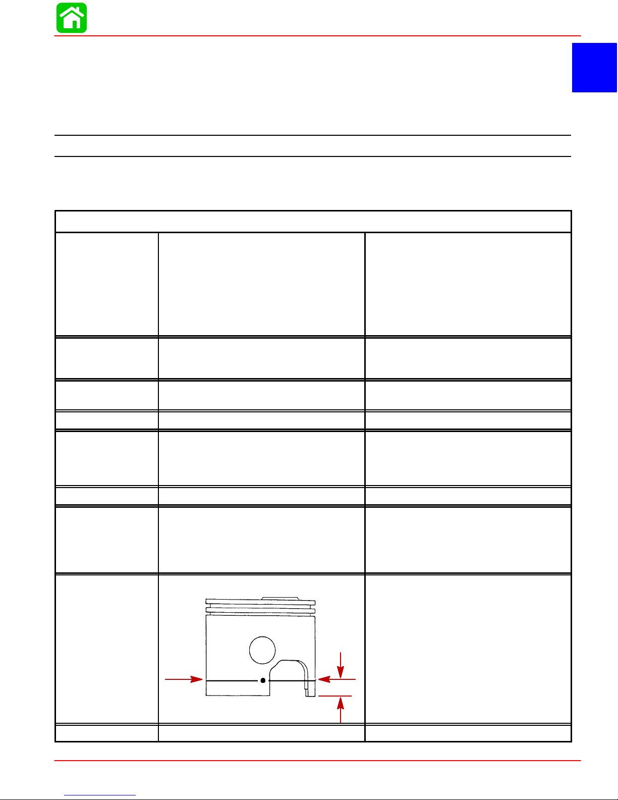
Dimension
“A” at Right
Angle (90
to Piston
Pin
°)
.700
17.78mm
V-6 Cylinder, Two Cycle, Direct Injected
153 cu. in. (2508 cc) 60° Vee
3.501 in. (88.925 mm)
3.516 in. (89.306 mm)
0.003 in. (0.076 mm)
Cast Iron
Aluminum
3.4925 in. ± .0005 in. (88.7095 mm ±
0.0127 mm)
3.5075 in. ± 0.0005 in.
(89.0905 mm ± 0.0127 mm)
3.4925 in. ± .0005 in.
(88.7095 mm ± .0127 mm)
Using a micrometer, measure dimension
“A” at location shown. Dimension “A”
should be 3.4925 in. ± .0005 for a STAN-
DARD size piston (new) Dimension “A”
will be 0.001 – 0.0015 less if coating is
worn off piston (used)
REEDS Reed Stand 0pen (Max.) 0.020 in. (0.50 mm)
90-855347R1 JANUARY 1999 Page 1A-1
Page 6

SPECIFICATIONS
Model 135/150 DFI
MID
SECTION
GEAR
HOUSING
Power Trim (Total Tilt Range)
Power Trim (Tilt Range)
Steering Pivot Range
Tilt Pin Adjustment Positions
Allowable Transom Thickness
Gear Ratio
Standard Ratio – 135
Standard Ratio – 150
Optional High Altitude Ratio
– 135
– 150
Gearcase Capacity
Pinion Height
Forward Gear Backlash
– 1.87:1
– 2.00:1
– 2.30:1
Reverse Gear Backlash
– Standard/Counter Rotation
Water Pressure @ RPM
73°
19°
60°
4
2-3/8 in. (6.03 cm)
2.00:1 12/24 Teeth
1.87:1 15/28 Teeth
2.30:1 13/30 Teeth
2.00:1 12/24 Teeth
22.5 fl. oz. (665.4 ml)
0.025 in. (0.635 mm)
.
0.017 in. – 0.028 in.
(0.431 mm – 0.711 mm)
0.015 in. – 0.022 in.
(0.381 mm – 0.558 mm)
0.018 in. – 0.023 in.
(0.460 mm – 0.584 mm)
0.030 in. to 0.050 in.
(0.076 mm to 0.127 mm)
12 PSI Minimum @ 5500 RPM
DIRECT
INJECTION
Injectors
– Quantity
– Injectors are Crank Angle Driven
by ECM
– #2 Cylinder
– #4 Cylinder
– #6 Cylinder
– #1 Cylinder
– #3 Cylinder
– #5 Cylinder
Fuel Line Pressure @ Injectors
Air Pressure
High Pressure Electric Fuel Pump
Amperage Draw
Low Pressure Electric Fuel Pump
Amperage Draw
Low Pressure Electric Fuel Pump
Output
Fuel Injector Ohm Resistance
Direct Injector Ohm Resistance
Fuel/Air Differential
6
WHT/RED + RED/WHT Leads
WHT/YEL + YEL/WHT Leads
WHT/PPL + PPL/WHT Leads
WHT/BRN + BRN/WHT Leads
WHT/ORG + ORG/WHT Leads
WHT/DRK BLU + DRK BLU/WHT
Leads
89 ± 2 psi (613.5 ± 13.8 kPa)
79 ± 2 psi (544.0 ± 13.8 kPa)
5 – 9 Amperes
1 – 2 Amperes
6 – 9 psi (41.37 – 62.04 kPa)
1.8 ± 0.1 Ω
1.3 ± 0.3 Ω
10 psi (68.5 kPa)
Page 1A-2 90-855347R1 JANUARY 1999
Page 7

Master Specifications
SPECIFICATIONS
Model 135/150 DFI
FUEL
SYSTEM
STARTING
SYSTEM
IGNITION
SYSTEM
Fuel
Recommended Gasoline
Recommended Oil
Gasoline/Oil Ratio
– @ Idle
– @ WOT
Fuel Pressure
Crankcase Pump
– @ Idle
– @ WOT
Electric Start – All Models
Starter Draw (Under Load)
Starter Draw (No Load)
Minimum Brush Length
Battery Rating
Type
Spark Plug Type
Spark Plug Gap
Maximum Timing
Idle Timing
Throttle Position Sensor 1 (Inner
TPS)
@ Idle
@ W.O.T
Throttle Position Sensor 2 (Outer
TPS)
@ Idle
@ W.O.T
Crank Position Sensor
Air Gap
Gasoline w/Oil Injection
Unleaded 87 Octane Minimum
Quicksilver TC-W3 Premium Plus 2
Cycle Outboard Oil
300 – 400:1
60:1
2 psi (13.8 kPa)
8 psi (55.2 kPa)
165 Amperes
30 Amperes
0.25 in. (65.4 mm)
1000 (Minimum) Marine Cranking Amps
(MCA)
750 (Minimum) Cold Cranking Amps
(CCA)
Digital Inductive
NGK PZFR5F-11
NGK ZFR5F-11 or
Champion RC12MC4
0.040 in. (1.0 mm)
Not Adjustable; Controlled by ECM
Not Adjustable; Controlled by ECM
3.70 – 4.90 VDC
0.30 – 1.80 VDC
0.10 – 1.50 VDC
3.20 – 4.90 VDC
0.025 in. – 0.040 in.
(0.635 mm – 1.01 mm)
CHARGING
SYSTEM
*Amperage listed is when battery is in a discharged state. If battery is fully charged, amperage readings will
be less.
90-855347R1 JANUARY 1999 Page 1A-3
Alternator Output (Regulated)
Brush Length
Voltage Output
Regulator Current Draw
32 - 38 Amperes @ 2000 RPM
@ Battery*
52 - 60 Amperes @ 2000 RPM
@ Alternator
Std Exposed Length:
0.413 in. (10.5 mm)
Min. Exposed Length:
0.059 in. (1.5 mm)
13.5 to 15.1 Volts
0.15 mA (Ign. Switch Off)
30.0 mA (Ign. Switch On)
Page 8

MAINTENANCE
IMPORTANT INFORMATION
Section 1B - Maintenance
Table of Contents
Specifications 1B-1. . . . . . . . . . . . . . . . . . . . . . . . . . . . . . . .
Gear Case Lubricant Capacity 1B-1. . . . . . . . . . . . . .
Special Tools 1B-2. . . . . . . . . . . . . . . . . . . . . . . . . . . . . . . .
Quicksilver Lubricant/Sealant 1B-2. . . . . . . . . . . . . . . . . .
Inspection and Maintenance Schedule 1B-4. . . . . . . . . .
Before Each Use 1B-4. . . . . . . . . . . . . . . . . . . . . . . . . .
After Each Use 1B-4. . . . . . . . . . . . . . . . . . . . . . . . . . . .
Every 100 Hours of Use or Once yearly,
Whichever occurs first 1B-4. . . . . . . . . . . . . . . . . . . . .
Flushing Engine 1B-5. . . . . . . . . . . . . . . . . . . . . . . . . . . . . .
Flushing Cooling System – Using Cowl
Flush Plug 1B-5. . . . . . . . . . . . . . . . . . . . . . . . . . . . . . . .
Flushing Cooling System – Using Flushing
Attachment 44357A2 1B-5. . . . . . . . . . . . . . . . . . . . . .
Specifications
1
B
Fuel System 1B-6. . . . . . . . . . . . . . . . . . . . . . . . . . . . . . . . .
Fuel Line Inspection 1B-6. . . . . . . . . . . . . . . . . . . . . . .
Water Separating Fuel Filter 1B-6. . . . . . . . . . . . . . . .
Corrosion Control Anode 1B-7. . . . . . . . . . . . . . . . . . . . . .
Spark Plug Inspection 1B-7. . . . . . . . . . . . . . . . . . . . . . . . .
Battery Inspection 1B-8. . . . . . . . . . . . . . . . . . . . . . . . . . . .
Fuse Replacement 1B-8. . . . . . . . . . . . . . . . . . . . . . . . . . .
Compressor Air intake Filter 1B-9. . . . . . . . . . . . . . . . . . .
Removal 1B-9. . . . . . . . . . . . . . . . . . . . . . . . . . . . . . . . .
Installation 1B-9. . . . . . . . . . . . . . . . . . . . . . . . . . . . . . . .
Lubrication Points 1B-9. . . . . . . . . . . . . . . . . . . . . . . . . . . .
Checking Power Trim Fluid 1B-11. . . . . . . . . . . . . . . . . . .
Gear Case Lubrication 1B-12. . . . . . . . . . . . . . . . . . . . . . .
Storage Preparation 1B-13. . . . . . . . . . . . . . . . . . . . . . . . .
Gear Case Lubricant Capacity
Gear Case Ratio Capacity
1.87:1
2.00:1
2.30:1
22.5 fl. oz. (665ml)
22.5 fl. oz. (665ml)
22.5 fl. oz. (665ml)
90-855347R1 JANUARY 1999 Page 1B-1
Page 9
MAINTENANCE
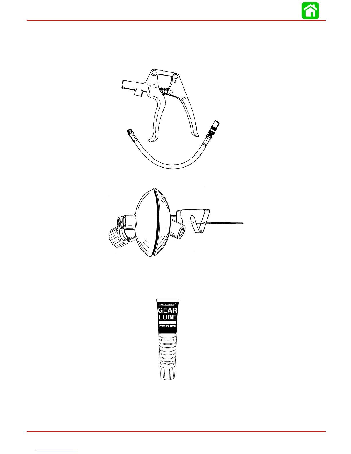
Special Tools
1. Grease Gun 91-37299A1
2. Flushing Attachment 44357A2
Quicksilver Lubricant/Sealant
1. Gear Lubricant - Premium Blend 92-19007A24
Page 1B-2 90-855347R1 JANUARY 1999
Page 10
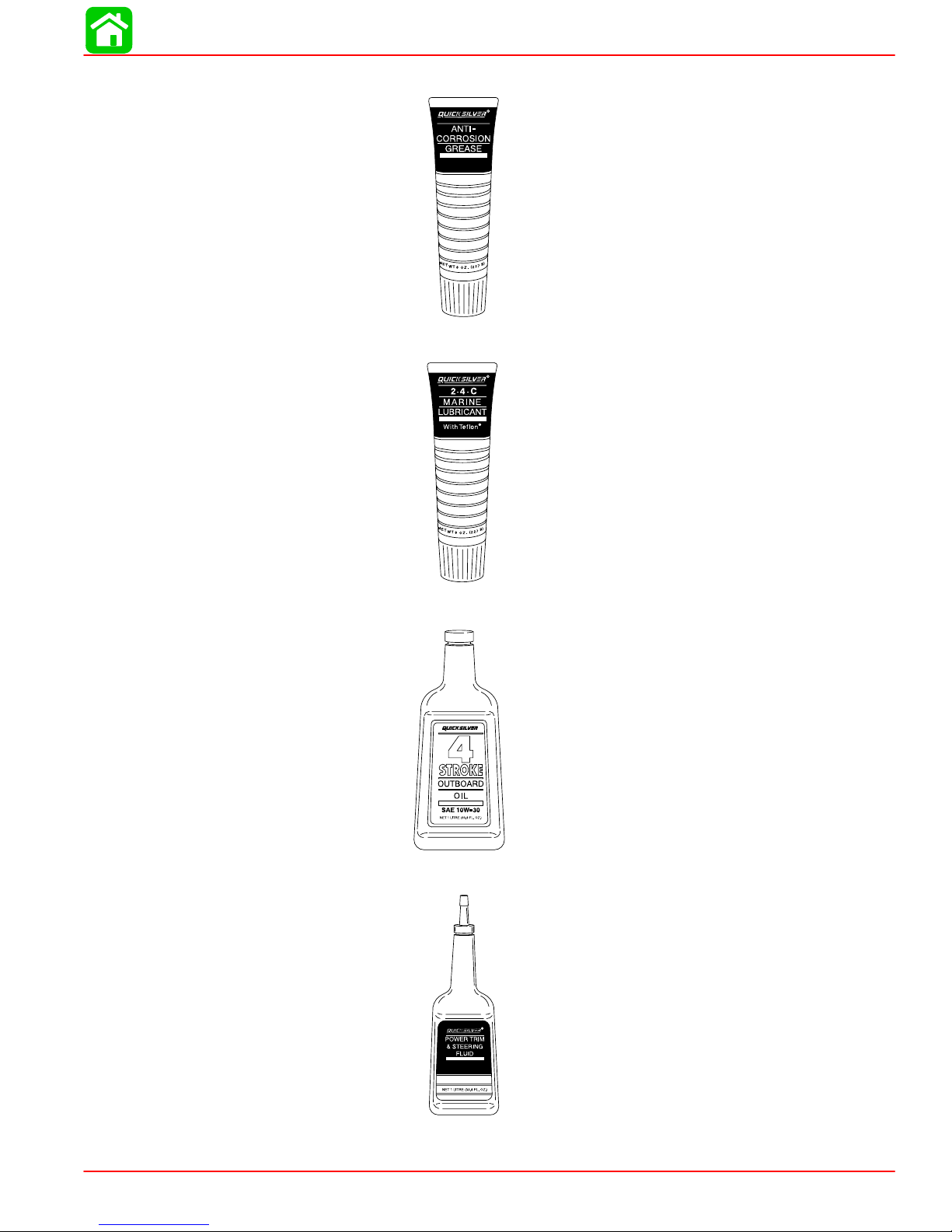
2. Anti-Corrosion Grease 92-78376A6
3. 2-4-C Marine Lubricant with Teflon 92-825407A12
MAINTENANCE
4. SAE 30W Motor Oil (Obtain Locally)
5. Quicksilver Power Trim and Steering Fluid 91-90100A12)
90-855347R1 JANUARY 1999 Page 1B-3
Page 11

MAINTENANCE
Inspection and Maintenance Schedule
Before Each Use
1. Check that lanyard stop switch stops the engine.
2. Visually inspect the fuel system for deterioration or leaks.
3. Check outboard for tightness on transom.
4. Check steering system for binding or loose components.
5. Visually check steering link rod fasteners for proper tightness.
6. Check propeller blades for damage.
After Each Use
1. Flush out the outboard cooling system if operating in salt or polluted water.
2. Wash off all salt deposits and flush out the exhaust outlet of the propeller and gear
case with fresh water if operating in salt water.
Every 100 Hours of Use or Once yearly, Whichever occurs first
1. Lubricate all lubrication points. Lubricate more frequently when used in salt water.
2. Inspect and clean spark plugs.
3. Replace water separating fuel filter
4. Replace compressor air intake filter.
5. Check corrosion control anodes. Check more frequently when used in salt water.
6. Drain and replace gear case lubricant.
7. Lubricate splines on the drive shaft.
8. Check power trim fluid.
9. Inspect battery.
10. Check control cable adjustments.
11. Remove engine deposits with Quicksilver Power Tune Engine Cleaner.
12. Check tightness of bolts, nuts, and other fasteners.
13. Replace water pump impeller (more often if overheating occurs or reduced water
pressure is noted).
These items should be serviced by an authorized dealer.
∗
∗
∗
∗
Page 1B-4 90-855347R1 JANUARY 1999
Page 12
Flushing Engine
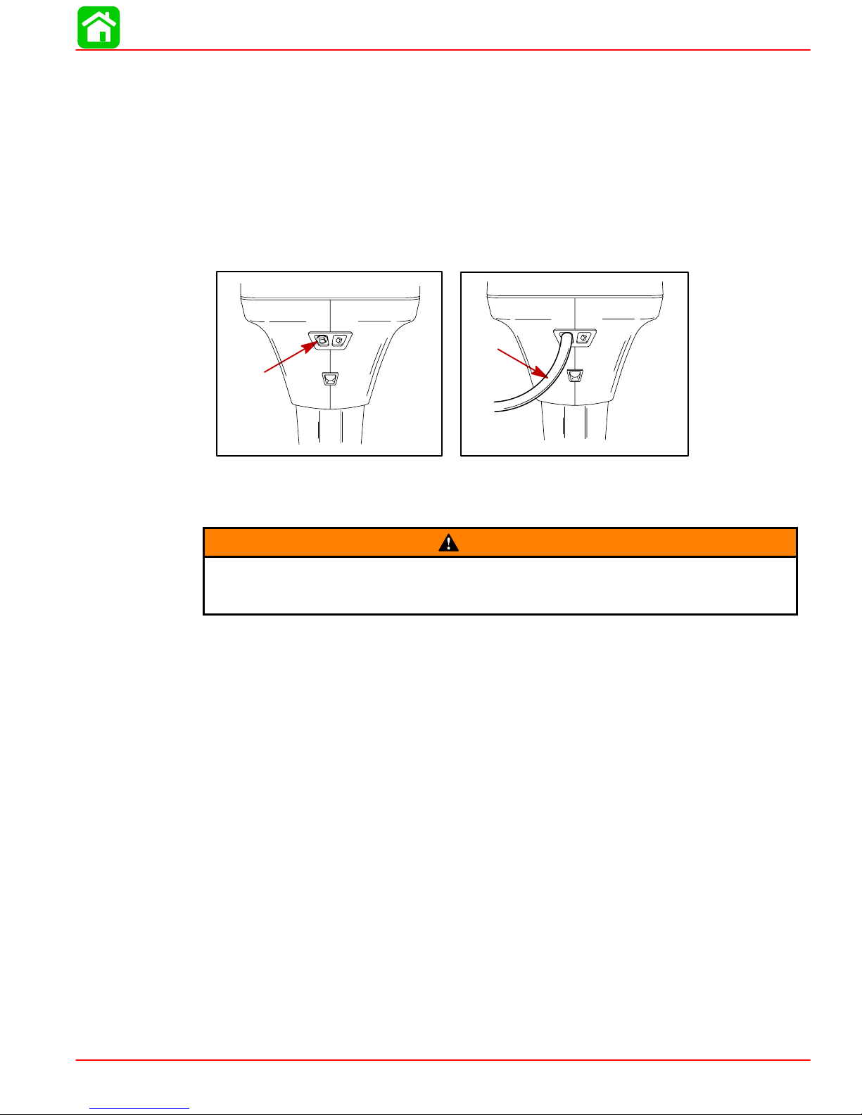
Flushing Cooling System – Using Cowl Flush Plug
Flush the internal water passages of the outboard with fresh water after each use in salt,
polluted or muddy water. This will help prevent a buildup of deposits from clogging the
internal water passages.
NOTE: Engine can be stopped or running at idle speed when flushing the cooling system.
Do not flush engine using a water system that exceeds 45 psi.
1. Remove the plug from fitting in the bottom cowl.
MAINTENANCE
2. Attach a water hose to the fitting. Turn water on and flush for 3 to 5 minutes.
Flushing Cooling System – Using Flushing Attachment 44357A2
WARNING
When flushing, verify that area in vicinity of propeller is clear and that no person
is standing nearby – to avoid possible injury . It is recommended to remove propeller as a precautionary measure.
1. Install Quicksilver Flushing Attachment 44357A2 (or equivalent tool) on the gear
housing from the FRONT side, positioning the rubber cups over the water intake
openings.
2. Connect hose [1/2 in. (12.7mm) I.D. or larger] between flushing attachment and water
tap.
IMPORTANT: To prevent water pump damage, do not start or run engine unless
cooling water is flowing.
3. With the outboard in the normal operating position (vertical), partially open water tap
(IT IS NOT NECESSARY to use full water pressure) and adjust water flow so that
there is a significant water loss around the rubber cups.
4. Start engine and idle in NEUTRAL. Increase engine speed, not to exceed 2500 RPM.
5. Flush or service engine as required. Verify adequate cooling water is provided.
a. Water must be discharged thru “tell tale.”
IMPORT ANT: Prevent engine overheating. If water flow is insufficient, stop engine
and determine cause before continuing.
b. Flush until discharge water is clear. In salt-water areas, run outboard 3 to 5 min-
utes.
c. Stop engine before turning off water.
6. Stop engine, turn water off and remove flushing attachment from gear housing.
90-855347R1 JANUARY 1999 Page 1B-5
Page 13
MAINTENANCE
IMPORTANT: While and after flushing, keep outboard in upright position until all
water has drained from drive shaft housing to prevent water from entering the powerhead via drive shaft housing and exhaust ports.
Fuel System
Avoid serious injury or death from gasoline fire or explosion. Carefully follow all
fuel system service instructions. Always stop the engine and DO NOT smoke or
allow open flames or sparks in the area while servicing any part of the fuel system.
Before servicing any part of the fuel system, stop engine and disconnect the battery . Drain
the fuel system completely . Use an approved container to collect and store fuel. Wipe up
any spillage immediately . Material used to contain spillage must be disposed of in an approved receptacle. Any fuel system service must be performed in a well ventilated area.
Inspect any completed service work for sign of fuel leakage.
Fuel Line Inspection
Visually inspect the fuel line and primer bulb for cracks, swelling, leaks, hardness, or other
signs of deterioration or damage. If any of these conditions is found, the fuel line or primer
bulb must be replaced.
WARNING
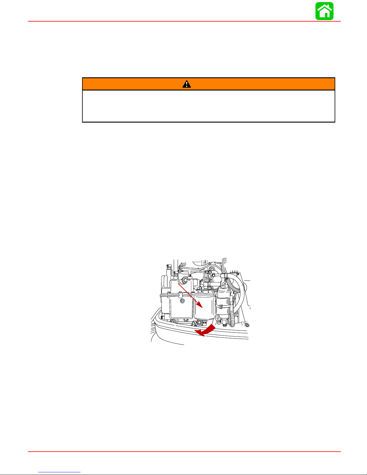
Water Separating Fuel Filter
NOTE: The warning system will turn on when water in the fuel filter reaches the full level.
1. This filter removes moisture and also debris from the fuel. If the filter becomes filled
with water, the water can be removed. If the filter becomes plugged with debris, the
filter must be replaced with a new filter.
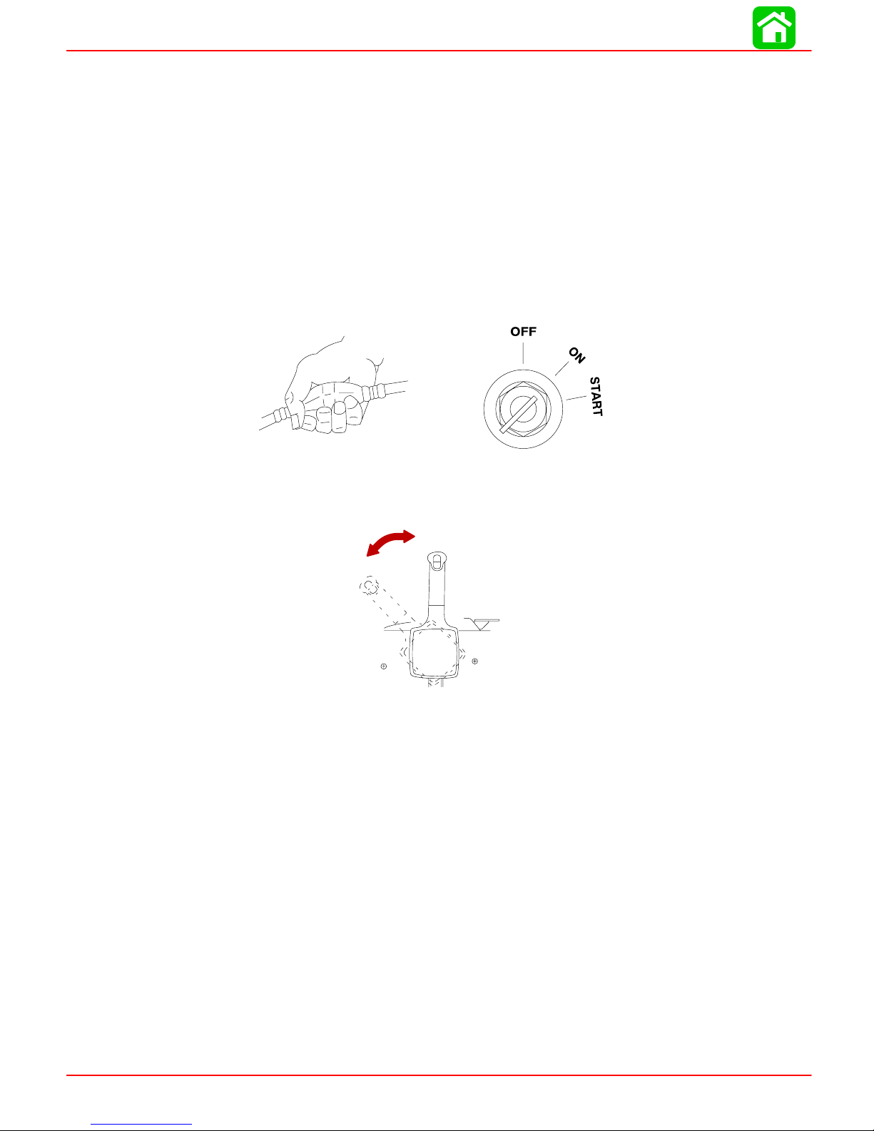
Remove and replace filter as follows:
a. Turn ignition key switch to OFF position.
b. Disconnect wire at bottom of filter.
c. Remove filter by turning the filter in the direction of the arrow (clockwise). Tip the
filter to drain fluid in a suitable container.
d. Lubricate the sealing ring on the filter with oil. Thread on the filter and tighten se-
curely by hand. Reconnect the wire to the filter.
IMPORT ANT : Visually inspect for fuel leakage from the filter by squeezing the primer bulb until firm, forcing fuel into the filter.
Page 1B-6 90-855347R1 JANUARY 1999
Page 14
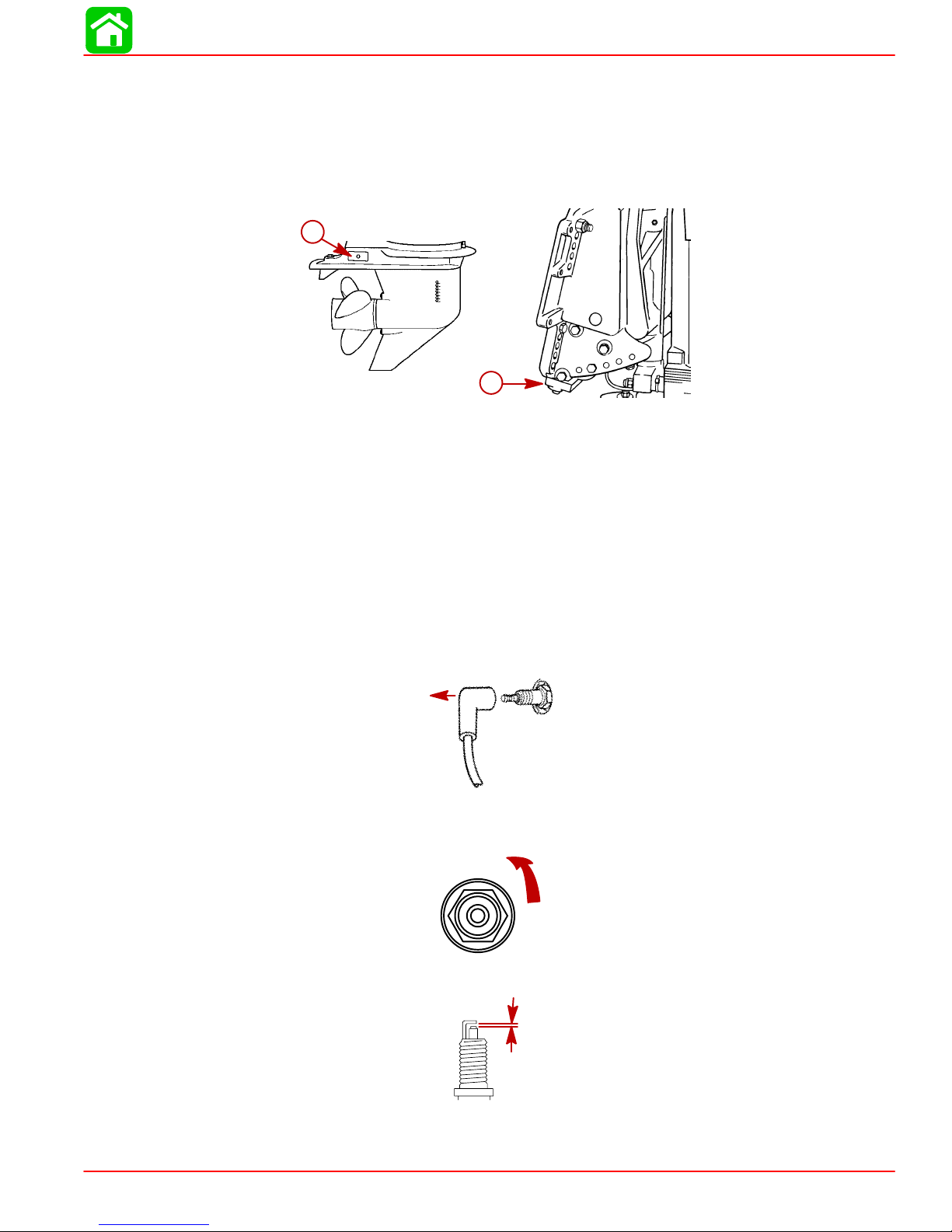
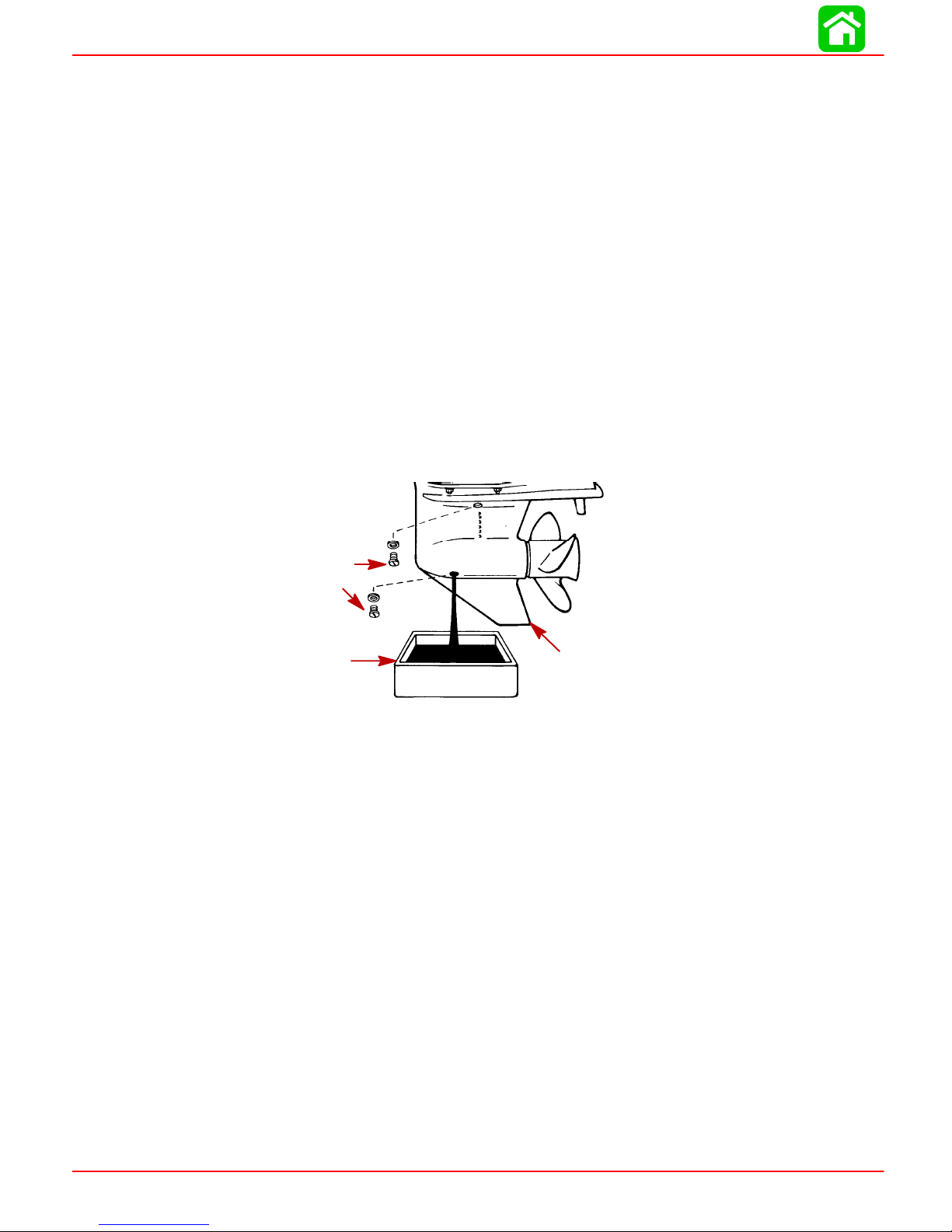
Corrosion Control Anode
The gear case has two corrosion control anodes (a). Another anode (b) is installed on the
bottom of the transom bracket assembly. An anode helps protect the outboard against
galvanic corrosion by sacrificing its metal to be slowly eroded instead of the outboard
metals.
a
Each anode requires periodic inspection especially in salt water which will accelerate the
erosion. T o maintain this corrosion protection, always replace the anode before it is completely eroded. Never paint or apply a protective coating on the anode as this will reduce
effectiveness of the anode.
MAINTENANCE
b
Spark Plug Inspection
Inspect spark plugs at the recommended intervals.
1. Remove the spark plug leads by twisting the rubber boots slightly and pull off. Inspect
spark plug boots and replace if cracked.
2. Remove the spark plugs to inspect and clean. Replace spark plug if electrode is worn
or the insulator is rough, cracked, broken, blistered or fouled.
3. Set the spark plug gap. See Specification Chart in General Information Section.
4. Before reinstalling spark plugs, clean away dirt on the spark plug seats. Install plugs
finger tight, and tighten 1/4 turn or torque to 20 lb. ft. (27 N·m).
90-855347R1 JANUARY 1999 Page 1B-7
Page 15
MAINTENANCE
Battery Inspection
The battery should be inspected at periodic intervals to ensure proper engine starting
capability.
IMPORTANT: Read the safety and maintenance instructions which accompany
your battery.
1. Turn off the engine before servicing the battery.
2. Add water as necessary to keep the battery full.
3. Make sure the battery is secure against movement.
4. Battery cable terminals should be clean, tight, and correctly installed. Positive to positive and negative to negative.
5. Make sure the battery is equipped with a nonconductive shield to prevent accidental
shorting of battery terminals.
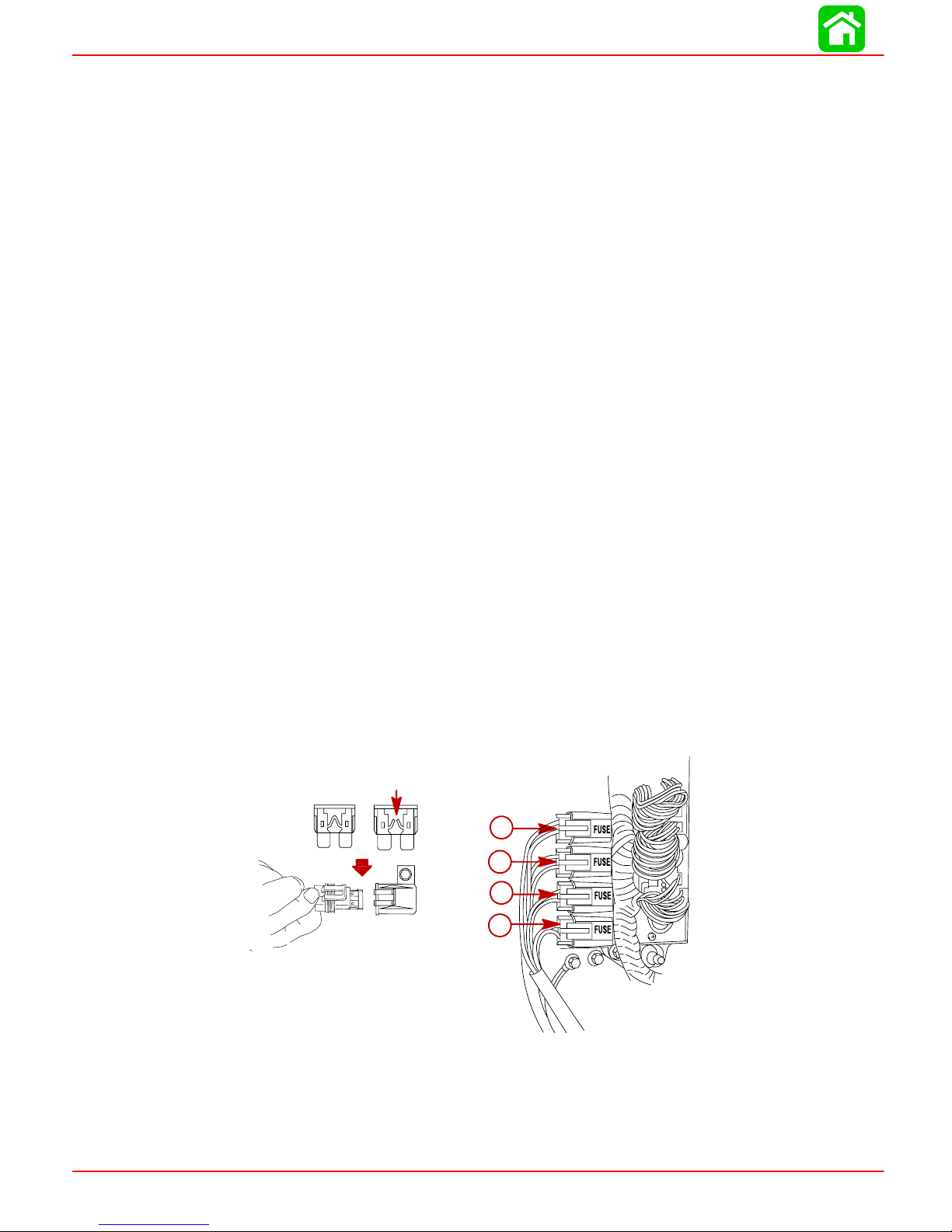
Fuse Replacement
IMPORTANT: Always carry spare SFE 20 AMP fuses.
The electrical wiring circuits on the outboard are protected from overload by fuses in the
wiring. If a fuse is blown, try to locate and correct the cause of the overload. If the cause
is not found, the fuse may blow again.
1. Open the fuse holder and look at the silver colored band inside the fuse. If band is
broken, replace the fuse. Replace fuse with a new fuse with the same rating.
2. The fuses and circuits are identified as follows:
a. Electric Fuel Pump Circuit – SFE 20 AMP Fuse.
b. Fuel/Air Injector Circuits – SFE 20 AMP Fuse.
c. Starting Circuit – SFE 20 AMP Fuse.
d. Ignition Coil/Oil Pump Circuit – SFE 20 AMP Fuse.
a
b
c
d
Page 1B-8 90-855347R1 JANUARY 1999
Page 16
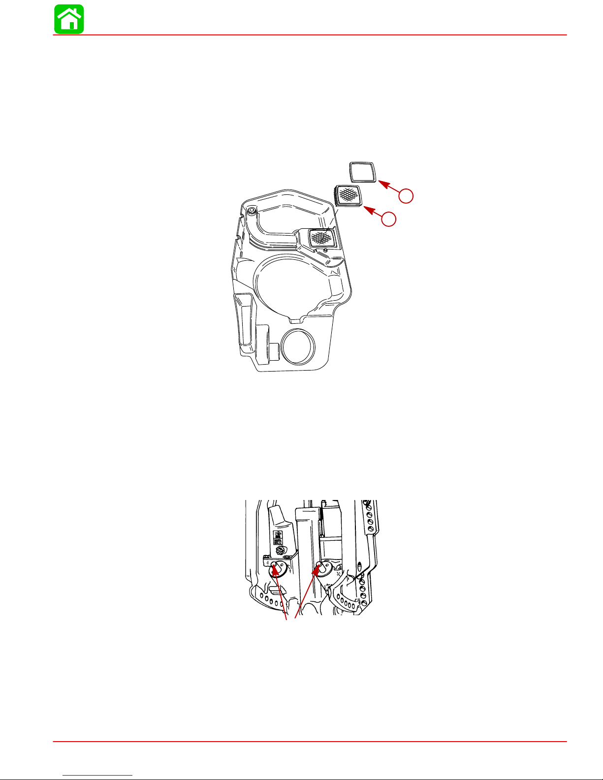
Compressor Air intake Filter
The filter should be changed every 100 hours of operation, or once a season. Never run
the engine without the air filter.
Removal
1. Remove flywheel cover from the engine. Snap out the retainer (a) and remove filter
(b).
MAINTENANCE
a
b
Installation
Install filter (b) into the cover. Secure filter into cover with retainer (a).
Lubrication Points
Lubricate Point 1 with Quicksilver Special Lubricant 101.
1. Trim Rod Ball Ends – Turn the ball ends to work the lubricant into the ball sockets.
1
90-855347R1 JANUARY 1999 Page 1B-9
Page 17

MAINTENANCE
Lubricate Point 2 with Quicksilver Anti-Corrosion Grease or 2-4-C Marine Lubricant with Teflon.
2. Propeller Shaft – Refer to Propeller Replacement for removal and installation of the
propeller. Coat the entire propeller shaft with lubricant to prevent the propeller hub
from corroding and seizing to the shaft.
2
Lubricate Points 3 thru 6 with Quicksilver 2-4-C Marine Lubricant with Teflon or Special
Lubricate 101.
3. Swivel Bracket – Lubricate through fitting.
4. Tilt Support Lever – Lubricate through fitting.
5. Tilt Tube – Lubricate through fitting.
5
3
4
Page 1B-10 90-855347R1 JANUARY 1999
Page 18
6. Steering Cable Grease Fitting (If Equipped) – Rotate steering wheel to fully retract the
steering cable end (a) into the outboard tilt tube. Lubricate through fitting (b).
The end of the steering cable must be fully retracted into the outboard tilt tube
before adding lubricant. Adding lubricant to steering cable when fully extended
could cause steering cable to become hydraulically locked. An hydraulically
locked steering cable will cause loss of steering control, possibly resulting in serious injury or death.
Lubricate Points 7 With Light Weight Oil.
7. Steering Link Rod Pivot Points – Lubricate pivot points.
MAINTENANCE
WARNING
6-b
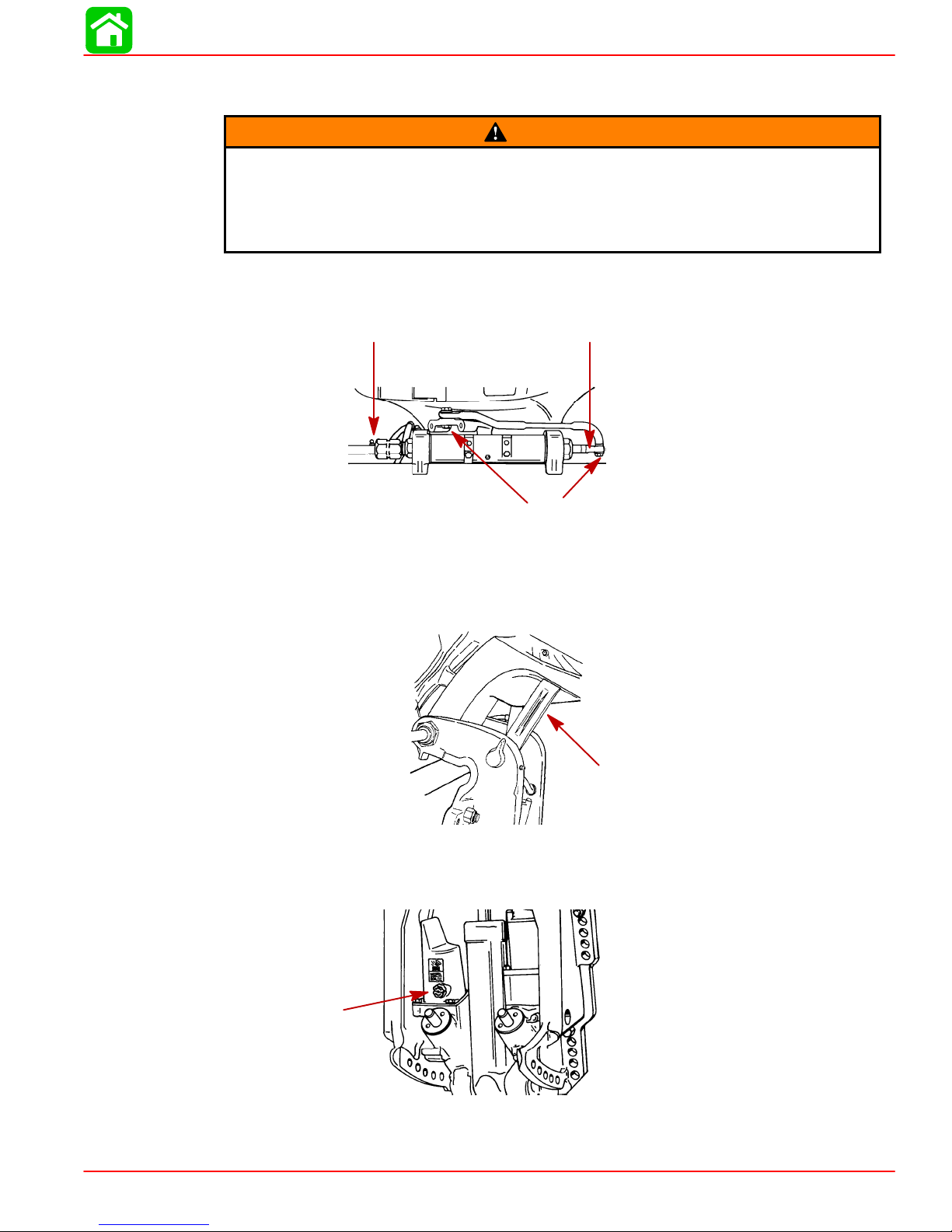
Checking Power Trim Fluid
8. Tilt outboard to the full up position and engage the tilt support lock.
6-a
7
8
9. Remove fill cap and check fluid level. The fluid level should be even with the bottom
of the fill hole. Add Quicksilver Power Trim & Steering Fluid. If not available, use automotive (ATF) automatic transmission fluid.
90-855347R1 JANUARY 1999 Page 1B-1 1
9
Page 19
MAINTENANCE
Gear Case Lubrication
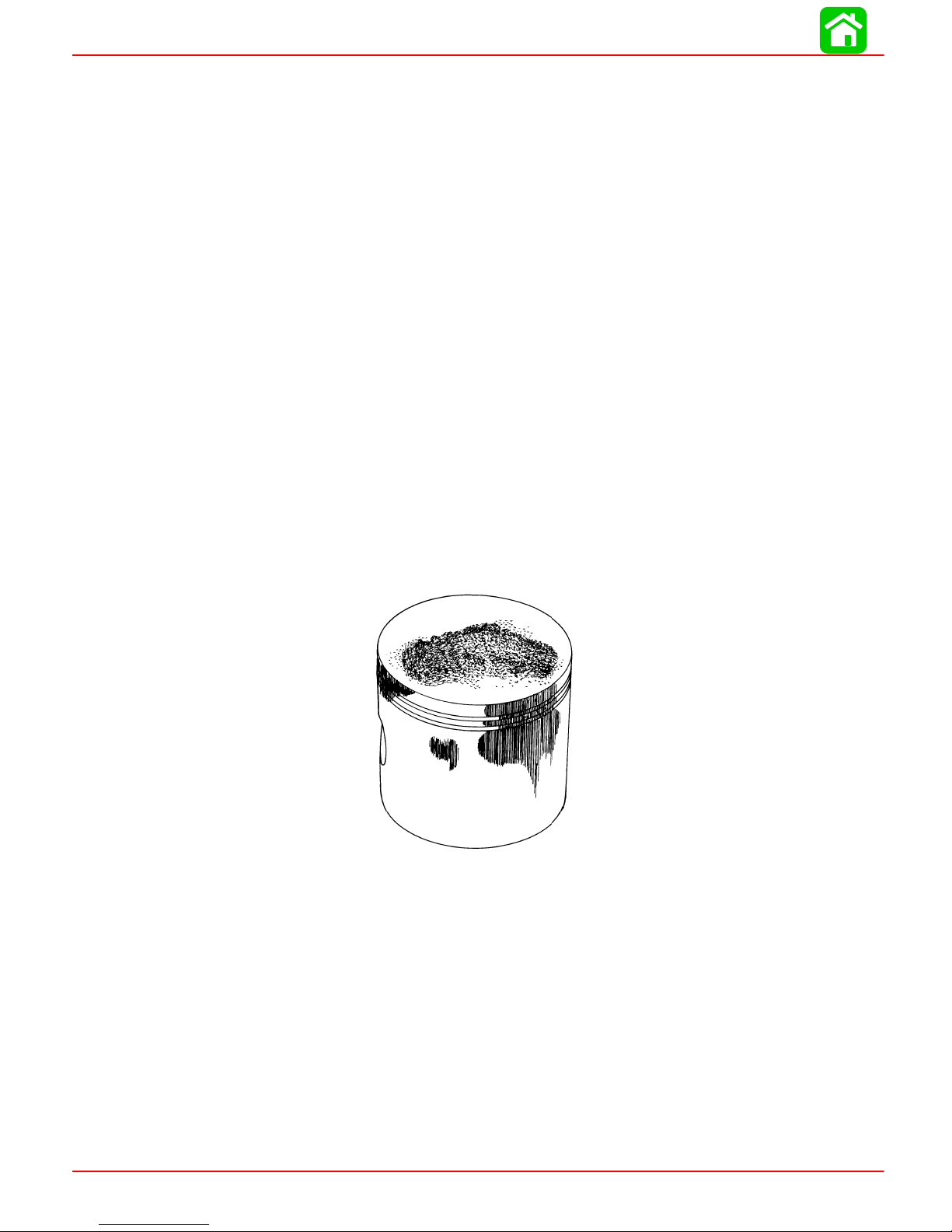
When adding or changing gear case lubricant, visually check for the presence of water
in the lubricant. If water is present, it may have settled to the bottom and will drain out prior
to the lubricant, or it may be mixed with the lubricant, giving it a milky colored appearance.
If water is noticed, have the gear case checked by your dealer.W ater in the lubricant may
result in premature bearing failure or, in freezing temperatures, will turn to ice and damage
the gear case.
Whenever you remove the fill/drain plug, examine the magnetic end for metal particles.
A small amount of metal filings or fine metal particles indicates normal gear wear. An excessive amount of metal filings or larger particles (chips) may indicate abnormal gear
wear and should be checked by an authorized dealer.
DRAINING GEAR CASE
NOTE: Some models may have the vent and fill/drain plugs on the opposite side.
1. Place outboard in a vertical operating position.
2. Place drain pan below outboard.
3. Remove vent plug and fill/drain plug and drain lubricant.
3
2
GEAR CASE LUBRICANT CAPACITY
Gear case lubricant capacity is approximately 22.5 fl. oz. (666 ml).
1
Page 1B-12 90-855347R1 JANUARY 1999
Page 20
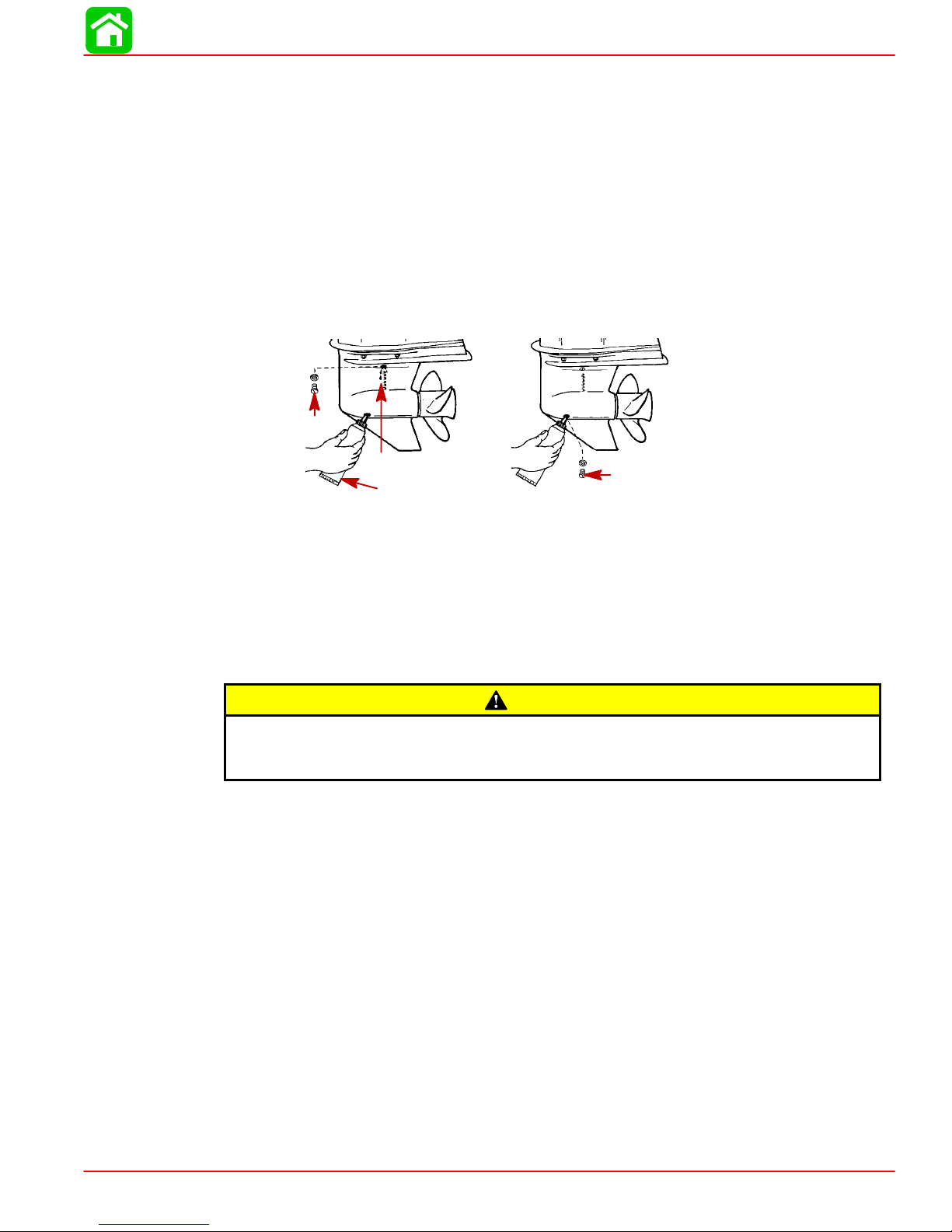
CHECKING GEAR CASE LUBRICANT LEVEL AND REFILLING GEAR CASE
NOTE: Some models may have the vent and fill/drain plugs on the opposite side.
1. Place outboard in a vertical operating position.
2. Remove vent plug (a).
3. Place lubricant tube (b) into the fill hole and add lubricant until it appears at the vent
hole (c).
IMPORTANT: Replace sealing washers if damaged.
4. Stop adding lubricant. Install the vent plug and sealing washer (a) before removing
the lubricant tube.
5. Remove lubricant tube and reinstall cleaned fill/drain plug and sealing washer (d).
a
MAINTENANCE
c
1-5
b
STORAGE PREPARATION
The major consideration in preparing your outboard for storage is to protect it from rust,
corrosion, and damage caused by freezing of trapped water.
The following storage procedures should be followed to prepare your outboard for out of
season storage or prolonged storage (two months or longer).
Never start or run your outboard (even momentarily) without water circulating
through all the cooling water intake holes in the gear case to prevent damage to
the water pump (running dry) or overheating of the engine.
FUEL SYSTEM
IMPORTANT: Gasoline containing alcohol (ethanol or methanol) can cause a formation of acid during storage and can damage the fuel system. If the gasoline being used contains alcohol, it is advisable to drain as much of the remaining gasoline as possible from the fuel tank, remote fuel line, and engine fuel system.
d
CAUTION
Fill the fuel system (tank, hoses, fuel pumps, and fuel injection systems) with treated (stabilized) fuel to help prevent formation of varnish and gum. Proceed with following instructions.
1. Portable Fuel T ank – Pour the required amount of Quicksilver Gasoline Stabilizer (follow instructions on container) into fuel tank. Tip fuel tank back and forth to mix stabilizer with the fuel.
2. Permanently Installed Fuel Tank – Pour the required amount of Quicksilver Gasoline
Stabilizer (follow instructions on container) into a separate container and mix with approximately one quart (one liter) of gasoline. Pour this mixture into fuel tank.
90-855347R1 JANUARY 1999 Page 1B-13
Page 21

MAINTENANCE
3. Place the outboard in water or connect flushing attachment for circulating cooling
water. Run the engine at 2000 rpm for 25 minutes to allow treated fuel to fill the fuel
system.
PROTECTING INTERNAL ENGINE COMPONENTS
NOTE: Make sure the fuel system has been prepared for storage.
1. Remove the spark plugs and add approximately one ounce (30ml) of engine oil into
each spark plug hole. Rotate the flywheel manually several times to distribute the oil
in the cylinders. Reinstall spark plugs.
2. Remove the water separating fuel filter and empty contents into a suitable container.
Refer to Maintenance Section for removal and installation of filter. Replace fuel filter
annually , or every 100 Hours of operation, or if large amount of fuel contamination is
present.
PROTECTING EXTERNAL OUTBOARD COMPONENTS
1. Lubricate all outboard components listed in the Inspection and Maintenance
Schedule.
2. Touch up any paint nicks. See your dealer for touch-up paint.
3. Spray Quicksilver Corrosion Guard on external metal surfaces (except corrosion control anodes).
GEAR CASE
Drain and refill the gear case lubricant (refer to maintenance procedure).
POSITIONING OUTBOARD FOR STORAGE
Store outboard in an upright (vertical) position to allow water to drain out of outboard.
If outboard is stored tilted up in freezing temperature, trapped cooling water or
rain water that may have entered the propeller exhaust outlet in the gear case
could freeze and cause damage to the outboard.
BATTERY STORAGE
1. Follow the battery manufacturers instructions for storage and recharging.
2. Remove the battery from the boat and check water level. Recharge if necessary.
3. Store the battery in a cool, dry place.
4. Periodically check the water level and recharge the battery during storage.
CAUTION
Page 1B-14 90-855347R1 JANUARY 1999
Page 22
GENERAL INFORMATION
IMPORTANT INFORMATION
Section 1C - General Information
Table of Contents
Serial Number Location 1C-1. . . . . . . . . . . . . . . . . . . . . . .
Conditions Affecting Performance 1C-2. . . . . . . . . . . . . .
Weather 1C-2. . . . . . . . . . . . . . . . . . . . . . . . . . . . . . . . . .
Boat 1C-3. . . . . . . . . . . . . . . . . . . . . . . . . . . . . . . . . . . . .
Trim 1C-4. . . . . . . . . . . . . . . . . . . . . . . . . . . . . . . . . . . . .
Engine 1C-6. . . . . . . . . . . . . . . . . . . . . . . . . . . . . . . . . . .
Engine Compression 1C-6. . . . . . . . . . . . . . . . . . . . . . .
Following Complete Submersion 1C-7. . . . . . . . . . . . . . .
Salt Water Submersion 1C-7. . . . . . . . . . . . . . . . . . . . .
Submerged While Running 1C-7. . . . . . . . . . . . . . . . .
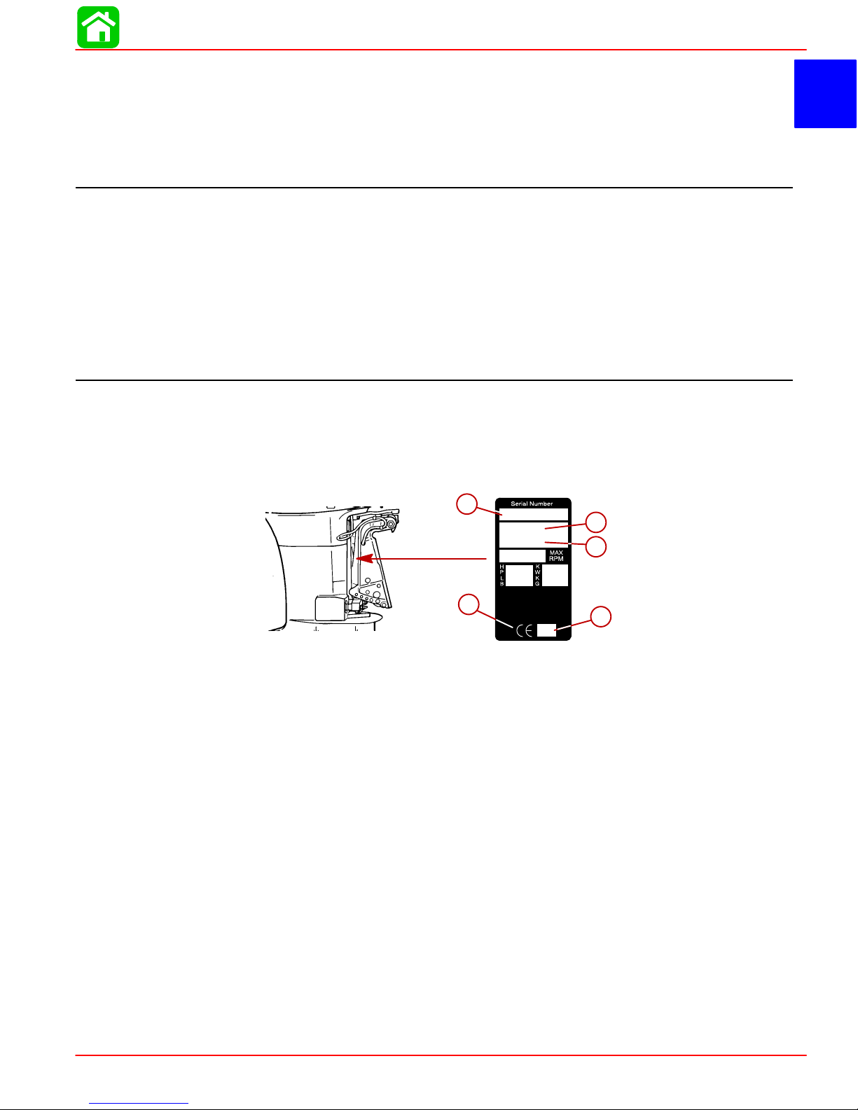
Serial Number Location
The engine serial number is located on the lower starboard side of the engine block. A
serial number is also located on the starboard side of the swivel bracket.
1
C
Model 135/150 DFI Powerhead Front View 1C-9. . . . . .
Model 135/150 DFI Powerhead Starboard View 1C-10
Model 135/150 DFI Powerhead Port View 1C-11. . . . . .
Model 135/150 DFI Powerhead Top View 1C-12. . . . . .
Model 135/150 DFI Powerhead Aft View 1C-13. . . . . .
Painting Procedures 1C-14. . . . . . . . . . . . . . . . . . . . . . . .
Cleaning & Painting Aluminum Propellers & Gear
Housings 1C-14. . . . . . . . . . . . . . . . . . . . . . . . . . . . . . .
Decal Application 1C-15. . . . . . . . . . . . . . . . . . . . . . . . . . .
Decal Removal 1C-15. . . . . . . . . . . . . . . . . . . . . . . . . .
Instructions for “Wet” Application 1C-15. . . . . . . . . .
a-Serial Number
b-Model Year
c-Model Description
d-Year Manufactured
e-Certified Europe Insignia
a
OGXXXXXX
19XX
XXXX
b
c
e
XX
d
90-855347R1 JANUARY 1999 Page 1C-1
Page 23
GENERAL INFORMATION
Conditions Affecting Performance
Weather
Weather conditions exert a profound effect on power output of internal combustion engines. Established horsepower ratings refer to the power that the engine will produce at
its rated RPM under a specific combination of weather conditions.
Corporations internationally have settled on adoption of I.S.O. (International Standards
Organization) engine test standards, as set forth in I.S.O. 3046 standardizing the computation of horsepower from data obtained on the dynamometer, correcting all values to the
power that the engine will produce at sea level, at 30% relative humidity at 77° F (25°C)
temperature and a barometric pressure of 29.61 inches of mercury.
Summer conditions of high temperature, low barometric pressure and high humidity all
combine to reduce engine power. This is reflected in decreased boat speeds – as much
as 2 or 3 mph. Nothing will regain this speed for the boater but the coming of cool, dry
weather.
In pointing out the consequences of weather effects, an engine – running on a hot, humid
summer day – may lose as much as 14% of the horsepower it would produce on a dry,
brisk spring or fall day. The horsepower that any internal combustion engine produces
depends upon the density of the air that it consumes and this density is dependent upon
the temperature of the air, its barometric pressure and water vapor (or humidity) content.
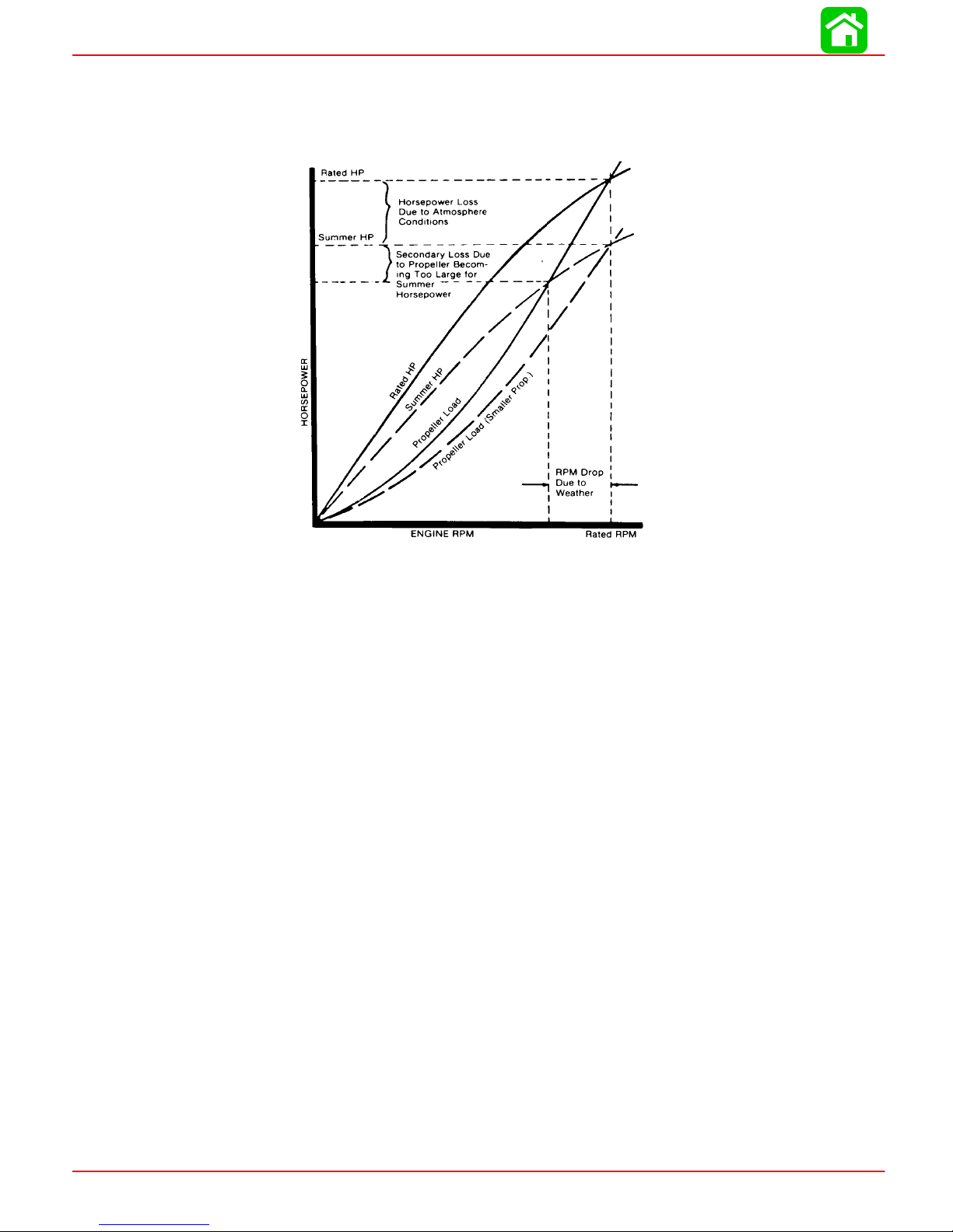
Accompanying this weather-inspired loss of power is a second but more subtle loss. At
rigging time in early spring, the engine was equipped with a propeller that allowed the
engine to run within its recommended RPM range at full throttle. With the coming of the
summer weather and the consequent drop in available horsepower, this propeller will, in
effect, become too large. Consequently, the engine operates at less than its recommended RPM.
Due to the horsepower/RPM characteristics of an engine, this will result in further loss of
horsepower at the propeller with another decrease in boat speed. This secondary loss
can be regained by switching to a smaller pitch propeller that allows the engine to run
again at recommended RPM.
Page 1C-2 90-855347R1 JANUARY 1999
Page 24

To obtain optimum engine performance under changing weather conditions, the engine
MUST be propped to allow it to operate at or near the top end of the recommended maximum RPM range at wide-open-throttle with a normal boat load.
This will allow the engine to develop full power while operating in an RPM range that discourages damaging detonation.
Boat
WEIGHT DISTRIBUTION
1. Proper positioning of the weight inside the boat (persons and gear) has a significant
effect on the boat’s performance, for example:
a. Shifting weight to the rear (stern)
b. Shifting weight to the front (bow)
GENERAL INFORMATION
(1.)Generally increases top speed.
(2.)If in excess, can cause the boat to porpoise.
(3.)Can make the bow bounce excessively in choppy water.
(4.)Will increase the danger of the following wave splashing into the boat when
coming off plane.
(1.)Improves ease of planing off.
BOTTOM
(2.)Generally improves rough water ride.
(3.)If excessive, can make the boat veer back-and-forth (bow steer).
1. Boat Bottom: For maximum speed, a boat bottom should be nearly a flat plane where
it contacts the water and particularly straight and smooth in fore-and-aft direction.
a. Hook: Exists when bottom is concave in fore-and -aft direction when viewed from
the side. When boat is planing, “hook” causes more lift on bottom near transom
and allows bow to drop, thus greatly increasing wetted surface and reducing boat
speed. “Hook” frequently is caused by supporting boat too far ahead of transom
while hauling on a trailer or during storage.
b. Rocker: The reverse of hook and much less common. “Rocker” exists if bottom
is convex in fore-and-aft direction when viewed from the side, and boat has strong
tendency to porpoise.
c. Surface Roughness: Moss, barnacles, etc., on boat or corrosion of motor’s gear
housing increase skin friction and cause speed loss. Clean surfaces when necessary .
d. Gear Housing: If unit is left in the water, marine vegetation may accumulate over
a period of time. This growth MUST be removed from unit before operation, as it
may clog the water inlet holes in the gear housing and cause the engine to overheat.
90-855347R1 JANUARY 1999 Page 1C-3
Page 25

GENERAL INFORMATION
Trim
TRIMMING OUTBOARD “OUT” (“UP”)
Excessive trim “out” also may reduce the stability of some high speed hulls. T o
correct instability at high speed, reduce the power GRADUALL Y and trim the outboard “in” slightly before resuming high speed operation. (Rapid reduction in
power will cause a sudden change of steering torque and may cause additional
momentary boat instability.)
1. Will lift bow of boat, generally increasing top speed.
2. Transfers steering torque harder to left on single outboard installations below 23 in.
(584mm) transom height.
3. Increases clearance over submerged objects.
4. In excess, can cause porpoising and/or ventilation.
5. If trimmed out beyond the water pickup, reduced water supply can cause overheating
resulting in engine damage.
WARNING
Page 1C-4 90-855347R1 JANUARY 1999
Page 26

TRIMMING OUTBOARD “IN” (“DOWN”) CHARACTERISTICS
WARNING
Excessive speed at minimum trim “in” may cause undesirable and/or unsafe
steering conditions. Each boat should be tested for handling characteristics after
any adjustment is made to the angle (trim adjustment bolt relocation.)
1. Will help planing off, particularly with a heavy load.
2. Usually improves ride in choppy water.
3. In excess, can cause boat to veer to the left or right (bow steer).
4. Transfers steering torque harder to right (or less to the left) on single outboard installations.
5. Improves planing speed acceleration (by moving trim adjustment bolt one hole closer
to transom).
WATER ABSORPTION
It is imperative that all through hull fasteners be coated with a quality marine sealer at time
of installation. Water intrusion into the transom core and/or inner hull will result in additional boat weight (reduced boat performance), hull decay and eventual structural failure.
CAVITATION
GENERAL INFORMATION
VENTILATION
Cavitation is caused by water vapor bubbles forming either from a sharp edge or angle
on the gear case or from an irregularity in the propeller blade itself. These vapor bubbles
flow back and collapse when striking the surface of the propeller blade resulting in the erosion of the propeller blade surface. If allowed to continue, eventual blade failure (breakage) will occur.
Ventilation occurs when air is drawn from the water’s surface (excessive trim out angle)
or from the engine exhaust flow (wrong propeller/propeller hardware installed or gear
case labyrinth seal worn) into the propeller blades. These air bubbles strike the propeller
blade surface and cause erosion of the blade surface. If allowed to continue, eventual
blade failure (breakage) will occur.
90-855347R1 JANUARY 1999 Page 1C-5
Page 27
GENERAL INFORMATION
Engine
DETONATION
Detonation in a 2-cycle engine resembles the “pinging” heard in an automobile engine.
It can be otherwise described as a tin-like “rattling” or “plinking” sound.
Detonation is an explosion of an unburned portion of the fuel/air charge after the spark
plug has fired. Detonation creates severe shock waves in the engine, and these shock
waves often find or create a weakness: The dome of a piston, cylinder head/gasket, piston
rings or piston ring lands, piston pin and roller bearings.
A few of the most common causes of detonation in a marine 2-cycle application are as
follows:
• Over-advanced ignition timing.
• Use of low octane gasoline.
• Propeller pitch too high (engine RPM below recommended maximum range).
• Lean fuel mixture at or near wide-open-throttle.
• Spark plugs (heat range too hot – incorrect reach – cross-firing).
• Inadequate engine cooling (deteriorated cooling system).
Detonation usually can be prevented if:
1. The engine is correctly set up.
2. Diligent maintenance is applied to combat the detonation causes.
Engine Compression
Engine compression should be checked with engine block warm, throttle shutter wide
open, all spark plugs removed and using a fully charged battery . Normal compression for
all cylinders should be 1 10 to 130 psi (758.5 to 896.4 kPa). Cylinders should not vary more
than 15 psi (103.4 kPa) between one another. A variance of more than 15 psi would indicate the need for a power head inspection/disassembly.
51115
Page 1C-6 90-855347R1 JANUARY 1999
Page 28

Following Complete Submersion
Salt Water Submersion
Due to the corrosive effect of salt water on internal engine components, complete disassembly is necessary before any attempt is made to start the engine.
Submerged While Running
When an engine is submerged while running, the possibility of internal engine damage
is greatly increased. If, after engine is recovered and with spark plugs removed, engine
fails to turn over freely when turning flywheel, the possibility of internal damage (bent connecting rod and/or bent crankshaft) exists. If this is the case, the powerhead must be disassembled.
SUBMERGED ENGINE (FRESH WATER)
IMPORT ANT: Engine should be run within 2 hours after recovery, or serious internal damage may occur. If unable to start engine in this period, disassemble engine
and clean all parts. Apply oil as soon as possible.
NOTE: If sand has entered the air intake on the engine, do not attempt to the start the
engine. Sand will cause internal engine damage. disassembly is required to clean all internal engine components of sand.
GENERAL INFORMATION
1. Recover engine from water as quickly as possible.
2. Remove cowling.
3. Clean the exterior of the outboard with fresh water.
4. Dry all wiring and electrical components using compressed air.
5. Drain water from fuel system as follows:
a. Disconnect remote fuel hose from engine.
b. Remove drain plug from vapor separator and drain fuel/water. Reinstall plug after
draining.
c. Remove the fuel hose from bottom of port side fuel rail and drain fuel/water. Rein-
stall hose.
d. Remove the water separating fuel filter and empty contents.
6. Drain water from air compressor system as follows:
a. Dry or replace the air filter for the compressor.
b. Remove air outlet hose for the air compressor and drain water from compressor
and hose. Reinstall hose.
c. Remove the air hose from bottom of port side fuel rail and drain water. Reinstall
hose.
7. Drain water from engine as follows:
a. Remove air sensor from front of the air plenum. Tilt up the outboard and drain wa-
ter out of the air plenum through the air sensor mounting hole. Reinstall Sensor.
b. Remove spark plugs from engine.
c. Rotate flywheel manually to blow out any water from the cylinders.
d. Add approximately one ounce (30ml) of engine oil into each spark plug hole. Ro-
tate the flywheel manually several times to distribute the oil in the cylinders. Rein-
stall spark plugs.
90-855347R1 JANUARY 1999 Page 1C-7
Page 29
GENERAL INFORMATION
8. Drain water from the oil injection system as follows:
a. Remove remote oil hose (black without blue stripe) from pulse fitting on starboard
side of engine.
b. Drain any water from hose and reconnect.
c. If water was present in hose, check for water in the remote oil tank. Drain tank if
water is present.
9. Disassemble the engine starter motor and dry components.
10. Prime the oil injection pump as follows:
a. Fill the engine fuel system with fuel. Connect fuel hose and squeeze primer bulb
until it feels firm.
b. Turn the ignition key switch to the “ON” position.
c. Within the first 10 seconds after the key switch has been turned on, move the re-
mote control handle from neutral into forward gear 3 to 5 times. This will automatically start the priming process.
N
F
NOTE: Audible click from the oil pump will tell you the pump is priming. It may take a few
minutes for the pump to complete the priming process.
1 1. Attempt to start engine, using a fresh fuel source.If engine starts, it should be run for
at least one hour to eliminate any water in engine.
12. If engine fails to start, determine cause (fuel, electrical or mechanical).
Page 1C-8 90-855347R1 JANUARY 1999
Page 30
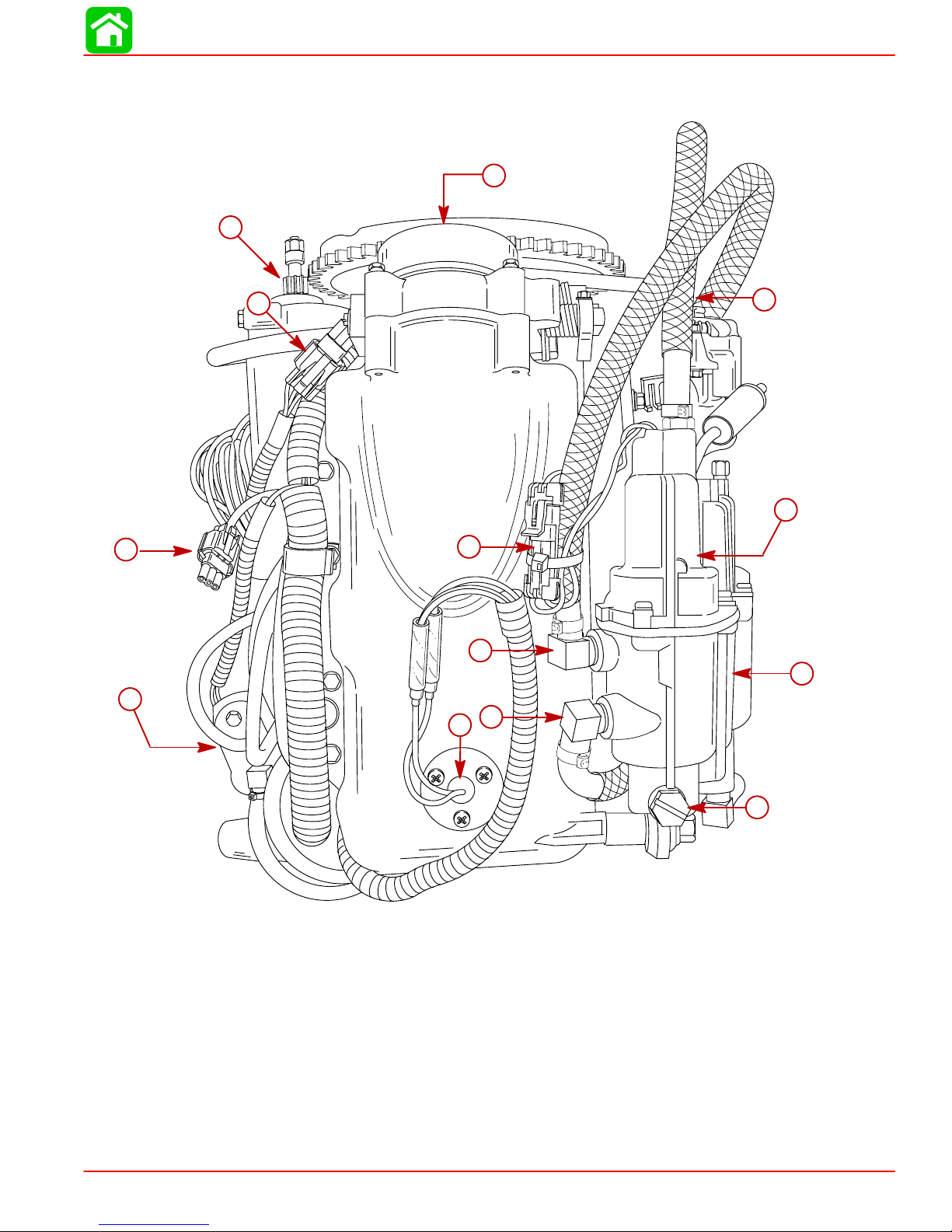
Model 135/150 DFI Powerhead Front View
12
11
GENERAL INFORMATION
10
13
1
9
7
6
2
8
5
4
1-High Pressure Electric Fuel Pump (Inside Vapor Separator)
2-Vapor Separator
3-Vapor Separator Drain Plug
4-Air Temperature Sensor
5-Fuel Hose Outlet from Low Pressure Electric Fuel Pump
6-Fuel Return Hose from Fuel Cooler
7-Electric Fuel Pump Harness Connection
8-Electric Oil Pump (Hidden)
9-Digital Diagnostic Terminal Harness Connection
10 - Crank Position Sensor Harness Connection
11 - Starter Motor
12 - Throttle Plate Assembly
13 - Fuel Hose Out to Fuel Rails (High Pressure)
90-855347R1 JANUARY 1999 Page 1C-9
3
57314
Page 31

GENERAL INFORMATION
Model 135/150 DFI Powerhead Starboard View
24
23
25
2
4
1
11
3
12
18
17
13
16
15
5
20
14
6
22
19
21
10
1-Fuel Pressure Test Valve
2-Air Compressor Oil Return Line
3-Crank Position Sensor
4-Throttle Plate/Air Plenum Assembly
5-Digital Diagnostic Terminal Connector
6-Oil Hose from Oil Reservoir to Oil Pump
7-Oil Pump
8-Main Power Relay(1998 Model)*
9-Trim DOWN Relay
10 - Trim UP Relay (1998 Model)*
11 - Temperature Sensor
12 - Electronic Control Module
13 - Starter Motor
NOTE: *The location for 1999 Model Main Power Relay and T rim UP Relay are reversed.
7
8
9
57317
14 - Starter Solenoid
15 - Oil Pump Fuse
16 - Harness Fuse (20 Ampere)
17 - ECM Fuse (20 Ampere)
18 - Electric Fuel Pump Fuse (20 Ampere)
19 - Air Hose
20 - Starboard Fuel Rail
21 - Fuel Hose
22 - #5 Fuel Injector
23 - #3 Fuel Injector
24 - #1 Fuel Injector
25 - Air Hose from Air Compressor
Page 1C-10 90-855347R1 JANUARY 1999
Page 32

Model 135/150 DFI Powerhead Port View
GENERAL INFORMATION
4
2
3
31
18
6
5
7
8
23
24
19
9
10
31
1
29
26
25
21
20
13
15
11
17
32
30
27
28
22
1-High Pressure Electric Fuel Pump
2-Fuel Out (90 psi)
3-Crank Position Sensor
4-Fuel Return from Fuel Cooler
5-Water Out (tell-tale) from Air Compressor
6-Air Restrictor/Air Inlet to Air Compressor
7-Air Compressor
8-Air Pressure Out from Air Compressor
9-Temperature Sensor (Air Compressor)
10 - #2 Fuel Injector
11 - #4 Fuel Injector
12 - #6 Fuel Injector
13 - Excess Air to Adaptor Plate
14 - Water Inlet to Fuel Cooler from Adaptor Plate
15 - Port Fuel Rail
16 - Water Out to Poppet Valve
12
14
16
57312
17 - Excess Fuel Return to Fuel Cooler
18 - Air Pressure Test Port
19 - 40 psi Check Valve
20 - Fuel Cooler
21 - Oil Reservoir
22 - Neutral Shift Interrupt Switch
23 - 60 Ampere Alternator
24 - Throttle Position Sensor (2 each)
25 - Low Pressure Electric Fuel Pump
26 - Fuel/Water Separator
27 - Fuel/Water Sensor
28 - Low Pressure Fuel Pump Inlet Hose
29 - Vapor Separator
30 - Vapor Separator Drain Plug
31 - Vent Canister
32 - Idle Stop Screw
90-855347R1 JANUARY 1999 Page 1C-11
Page 33

GENERAL INFORMATION
Model 135/150 DFI Powerhead Top View
20
18
19
1
2
13
14
17
12
15
16
11
21
23
7
3
5
6
8
22
4
1-Air Compressor Inlet Nozzle
2-Water Outlet (Tell-Tale) Hose
3-Thermostat Outlet Hose to Adaptor Plate
4-Fuel (90 PSI) to Fuel Rails
5-40 psi Check Valve
6-Fuel Return to Vapor Separator
7-Belt Tensioner
8-60 Ampere Alternator
9-Electric Fuel Pump
10 - Throttle Plate Assembly
11 - Crank Position Sensor
Page 1C-12 90-855347R1 JANUARY 1999
9
10
57313
12 - MAP Sensor Hose
13 - Oil Return Hose from Air Compressor
14 - Starter Motor
15 - Oil Hose from Oil Pump to Air Compressor
16 - Serial Number Plug
17 - Fuel Pressure Test Valve
18 - Air Hose (80 PSI) to Fuel Rail
19 - Check Valve
20 - Air Compressor
21 - Starboard to Port Thermostat Hose
22 - Vent Canister
23 - Throttle Plate Adjustment Screw
Page 34

Model 135/150 DFI Powerhead Aft View
GENERAL INFORMATION
26
25
28
2
4
1
5
3
6
7
18
9
8
19
27
21
17
20
11
10
24
16
23
22
14
1-Air Compressor Restrictor/Air Inlet
2-Water Out (tell-tale) from Air Compressor
3-Air Compressor Oil Inlet from Oil Pump
4-Air Compressor
5-Air Pressure Out (80 psi)
6-Fuel Pressure Test Valve
7-Check Valve
8-Excess Oil Return from Air Compressor
9-#1 Fuel Injector
10 - Starboard Fuel Rail
11 - #3 Fuel Injector
12 - #5 Fuel Injector
13 - Tell-Tale Outlet
14 - Flush Plug
15
13
15 - #5 Ignition Coil
16 - #3 Ignition Coil
17 - #1 Ignition Coil
18 - Water Inlet to Air Compressor
19 - #2 Ignition Coil
20 - MAP Sensor
21 - #4 Ignition Coil
22 - #6 Ignition Coil
23 - #6 Fuel Injector
24 - Air Regulator
25 - Port Fuel Rail
26 - #4 Fuel Injector
27 - Fuel Regulator
28 - #2 Fuel Injector
12
57315
90-855347R1 JANUARY 1999 Page 1C-13
Page 35

GENERAL INFORMATION
Painting Procedures
Cleaning & Painting Aluminum Propellers & Gear Housings
WARNING
Avoid serious injury from flying debris. Avoid serious injury from airborne particles. Use eye and breathing protection with proper ventilation.
PROPELLERS
1. Sand the entire area to be painted with 3M 120 Regalite Polycut or coarse ScotchBrite, disc or belts.
2. Feather edges of all broken paint edges. Try not to sand through the primer.
3. Clean the surface to be painted using PPG Industries DX330 Wax and Grease Remover or equivalent (Xylene or M.E.K.).
4. If bare metal has been exposed, use Quicksilver’s Light Gray Primer.
5. Allow a minimum of 1 hour dry time and no more than 1 week before applying the finish
coat.
6. Apply the finish coat using Quicksilver’s EDP Propeller Black.
GEAR HOUSINGS
The following procedures should be used in refinishing gear housings. This procedure will
provide the most durable paint system available in the field. The materials recommended
are of high quality and approximate marine requirements. The following procedure will
provide a repaint job that compares with a properly applied factory paint finish. It is recommended that the listed materials be purchased from a local Ditzler Automotive Finish Supply Outlet. The minimum package quantity of each material shown following is sufficient
to refinish several gear housings.
Procedure:
1. Wash gear housing with a muriatic acid base cleaner to remove any type of marine
growth, and rinse with water, if necessary.
2. Wash gear housing with soap and water, then rinse.
3. Sand blistered area with 3M 180 grit sandpaper or P180 Gold Film Disc to remove
paint blisters only. Feather edge all broken paint edges.
4. Clean gear housing thoroughly with (DX-330) wax and grease remover.
5. Spot repair surfaces where bare metal is exposed with (DX-503) alodine treatment.
IMPORT ANT : Do not use any type of aerosol spray paints as the paint will not properly adhere to the surface nor will the coating be sufficiently thick to resist future
paint blistering.
6. Mix epoxy chromate primer (DP-40) with equal part catalyst (DP-401) per manufacturers instructions, allowing proper induction period for permeation of the epoxy primer and catalyst.
7. Allow a minimum of one hour drying time and no more than one week before top coating assemblies.
8. Use Ditzler Urethane DU9000 for Mercury Black, DU34334 for Mariner Grey, and
DU35466 for Force Charcoal, and DU33414M for Sea Ray White. Catalyze all four
colors with Ditzler DU5 catalyst mixed 1:1 ratio. Reduce with solvents per Ditzler label.
Page 1C-14 90-855347R1 JANUARY 1999
Page 36

Be sure to comply with instructions on the label for ventilation and respirators.
Using a spray gun, apply one half to one mil even film thickness. Let dry , flash off
for five minutes and apply another even coat of one half to one mil film thickness.
This urethane paint will dry to the touch in a matter of hours, but will remain sensitive to scratches and abrasions for a few days.
9. The type of spray gun used will determine the proper reduction ratio of the paint.
IMPORTANT: Do not paint sacrificial zinc trim tab or zinc anode.
10. Cut out a cardboard “plug” for trim tab pocket to keep paint off of mating surface to
maintain good continuity circuitry between trim tab and gear housing.
Decal Application
Decal Removal
1. Mark decal location before removal to assure proper alignment of new decal.
2. Carefully soften decal and decal adhesive with a heat gun or heat blower while removing old decal.
GENERAL INFORMATION
CAUTION
3. Clean decal contact area with a 1:1 mixture of isopropyl alcohol and water.
4. Thoroughly dry decal contact area and check for a completely cleaned surface.
Instructions for “Wet” Application
NOTE: The following decal installation instructions are provided for a “Wet” installation.
All decals should be applied wet.
TOOLS REQUIRED
1. Plastic Squeegee*
2. Stick Pin
3. Dish Washing Liquid/Detergent without ammonia** “Joy” and “Drift” are known to
be compatible for this process.
** Automotive Body Filler Squeegee
** Do not use a soap that contains petroleum based solvents.
SERVICE TIP: Placement of decals using the “Wet” application will allow time to
position decal. Read entire installation instructions on this technique before proceeding.
TEMPERATURE
IMPORTANT: Installation of vinyl decals should not be attempted while in direct
sunlight. Air and surface temperature should be between 60°F (15°C) and 100°F
(38°C) for best application.
SURFACE PREPARATION
IMPORT ANT: Do not use a soap or any petroleum based solvents to clean application surface.
Clean entire application surface with mild dish washing liquid and water. Rinse surface
thoroughly with clean water.
90-855347R1 JANUARY 1999 Page 1C-15
Page 37

GENERAL INFORMATION
DECAL APPLICATION
1. Mix
NOTE: Leave protective masking, if present, on the face of decal until final steps of decal
installation. This will ensure that the vinyl decal keeps it’s shape during installation.
2. Place the decal face down on a clean work surface and remove the paper backing
3. Using a spray bottle, flood the entire “adhesive side” of the decal with the pre-mixed
4. Flood area where the decal will be positioned with wetting solution.
5. Position pre-wetted decal on wetted surface and slide into position.
6. Starting at the center of the decal, “lightly” squeegee out the air bubbles and wetting
7. Wipe decal surface with soft paper towel or cloth.
8. Wait 10 - 15 minutes.
9. Starting at one corner, “carefully and slowly” pull the masking of f the decal surface at
1
/2 ounce (16 ml) of dish washing liquid in one gallon (4 l) of cool water to use as
wetting solution.
from “adhesive side” of decal.
wetting solution.
solution with overlapping strokes to the outer edge of the decal. Continue going over
the decal surface until all wrinkles are gone and adhesive bonds to the cowl surface.
a 180° angle.
NOTE: T o remove any remaining bubbles, pierce the decal at one end of the bubble with
stick pin and press out the entrapped air or wetting solution with your thumb (moving toward the puncture).
Page 1C-16 90-855347R1 JANUARY 1999
Page 38
OUTBOARD MOTOR INSTALLATION
IMPORTANT INFORMATION
Section 1D - Outboard Motor Installation
Table of Contents
Installation Specifications 1D-1. . . . . . . . . . . . . . . . . . . . . .
Lifting Outboard 1D-1. . . . . . . . . . . . . . . . . . . . . . . . . . . . . .
Installing Outboard to Boat Transom 1D-2. . . . . . . . . . . .
Determining Recommended Outboard Mounting
Height 1D-2. . . . . . . . . . . . . . . . . . . . . . . . . . . . . . . . . . .
Installing Outboard 1D-3. . . . . . . . . . . . . . . . . . . . . . . . . . .
Drilling Outboard Mounting Holes 1D-3. . . . . . . . . . . .
Securing Outboard To Boat Transom 1D-4. . . . . . . . .
Steering Cable 1D-4. . . . . . . . . . . . . . . . . . . . . . . . . . . . . . .
Steering Link Rod 1D-5. . . . . . . . . . . . . . . . . . . . . . . . . . . .
Electrical, Hoses and Control Cables 1D-6. . . . . . . . . . .
Installation Note 1D-6. . . . . . . . . . . . . . . . . . . . . . . . . . .
Remote Wiring Harness 1D-6. . . . . . . . . . . . . . . . . . . .
Warning Gauge Harness 1D-7. . . . . . . . . . . . . . . . . . .
Battery Cables 1D-8. . . . . . . . . . . . . . . . . . . . . . . . . . . . . . .
Single Outboard 1D-8. . . . . . . . . . . . . . . . . . . . . . . . . . .
1
D
Dual Outboard 1D-8. . . . . . . . . . . . . . . . . . . . . . . . . . . .
Shift Cable 1D-9. . . . . . . . . . . . . . . . . . . . . . . . . . . . . . . . . .
Counter Rotation Outboards 1D-9. . . . . . . . . . . . . . . .
Installation 1D-10. . . . . . . . . . . . . . . . . . . . . . . . . . . . . .
Throttle Cable 1D-12. . . . . . . . . . . . . . . . . . . . . . . . . . . . .
Installation 1D-12. . . . . . . . . . . . . . . . . . . . . . . . . . . . . .
Front Clamp Reassembly 1D-13. . . . . . . . . . . . . . . . .
Filling Fuel System 1D-14. . . . . . . . . . . . . . . . . . . . . . . . .
Oil Injection Set-Up 1D-14. . . . . . . . . . . . . . . . . . . . . . . . .
Filling 1D-14. . . . . . . . . . . . . . . . . . . . . . . . . . . . . . . . . .
Priming the Oil Injection Pump 1D-15. . . . . . . . . . . .
Purging Air From the Engine Oil Tank 1D-16. . . . . .
Trim “In” Angle Adjustment 1D-16. . . . . . . . . . . . . . . . . .
Trim Tab Adjustment 1D-17. . . . . . . . . . . . . . . . . . . . . . . .
Models Without Power Steering 1D-17. . . . . . . . . . .
Models With Power Steering 1D-17. . . . . . . . . . . . . .
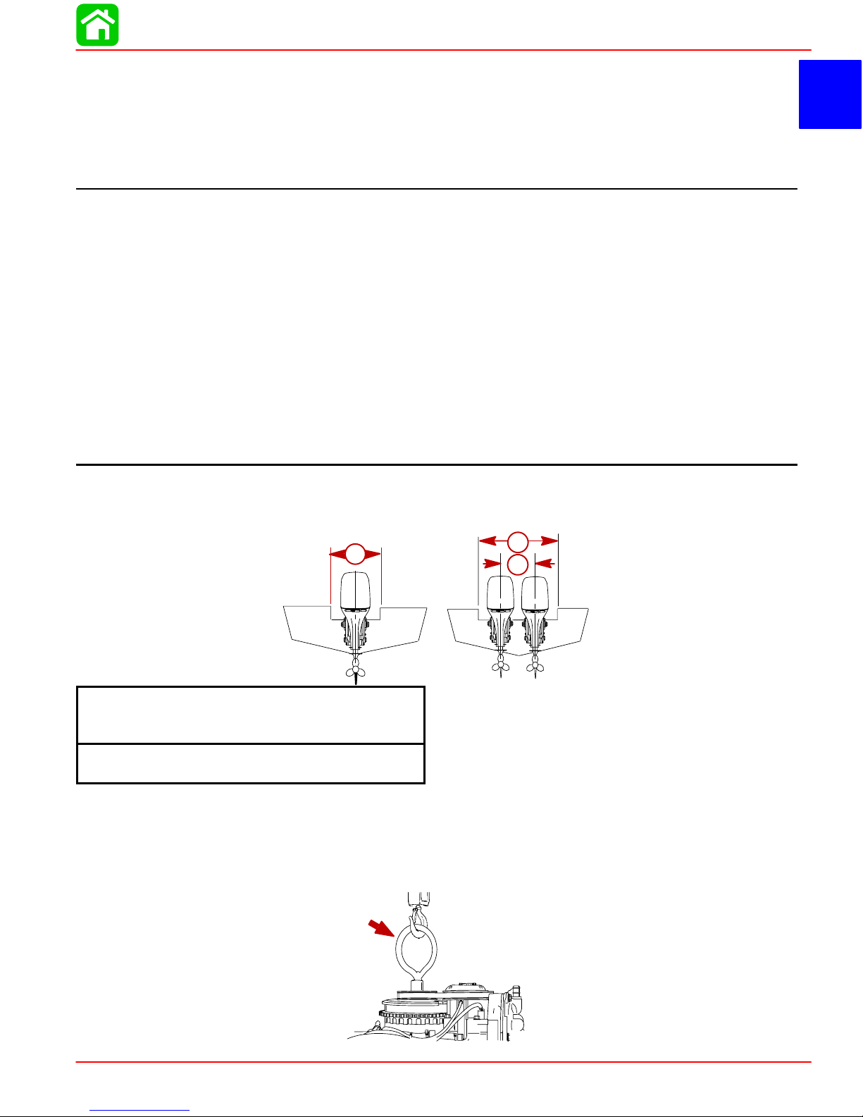
Installation Specifications
a
a
a – Transom Opening – Minimum
Single Engine – 33-3/8 in. (848 mm)
Dual Engines – 59-3/4 in. (1518 mm)
b – Engine Center Line For Dual Engine
26 in. (660mm) Minimum
Lifting Outboard
Electric Start Models – Remove plastic cap from flywheel hub. Thread lifting ring into
flywheel a minimum of 5 turns. Replace plastic cap after installation.
a
a
b
90-855347R1 JANUARY 1999 Page 1D-1
Page 39

OUTBOARD MOTOR INSTALLATION
Installing Outboard to Boat Transom
Determining Recommended Outboard Mounting Height
26 in.
(660mm)
(635mm)
(609mm)
e
Outboard
Mounting
Height (See
NOTE Below)
(584mm)
(560mm)
e
(533mm)
(508mm)
(482mm)
NOTE: Add 5 in. (127mm) for XL models and 10 in. (254mm) for XXL models
to listed outboard mounting height.
25 in.
24 in.
23 in.
22 in.
21 in.
20 in.
19 in.
10
b
c
b
a
d
20 30 40 50 60 70 80
Maximum Boat Speed Anticipated
NOTICE TO INSTALLER:
1. The outboard should be mounted high enough on the transom so that the exhaust
relief hole will stay at least 1 in. (25.4 mm) above the water line when the engine is
running at idle speed. This will prevent exhaust restriction.
2. The mounting height (e) of the outboard must not exceed 25 in. (635 mm) for L models, 30 in. (762 mm) for XL models and 35 in. (889 mm) for XXL models. Mounting the
outboard higher may cause damage to the gear case components.
a. This solid line is recommended to determine the outboard mounting height. In-
creasing the height of outboard generally will provide the following: 1) Less steering torque, 2) more top speed, 3) greater boat stability , but, 4) will cause more prop
“break loose” which may be particularly noticeable when planing off or with heavy
load.
b. These broken lines represent the extremes of known successful outboard mount-
ing height dimensions.
c. This line may be preferred to determine outboard mounting height dimension, if
maximum speed is the only objective.
d. This line may be preferred to determine outboard mounting height dimension for
dual outboard installation.
e. Outboard mounting height (height of outboard transom brackets from bottom of
boat transom). For heights over 22 in. (560mm), a propeller, that is designed for
surfacing operation is usually preferred.
Page 1D-2 90-855347R1 JANUARY 1999
Page 40

Installing Outboard
Drilling Outboard Mounting Holes
1. Attach (tape) engine mounting template (located with the installation manual) to boat
transom.
IMPORTANT: If using “Transom Drilling Fixture” (part number 91-98234A2), use
drill guide holes marked “A” when drilling outboard mounting holes.
OUTBOARD MOTOR INSTALLATION
b
a
a-Centerline of Transom
b-Transom Drilling Fixture (91-98234A2)
2. Mark and drill four 17/32 in. (13.5mm) mounting holes.
90-855347R1 JANUARY 1999 Page 1D-3
Page 41

OUTBOARD MOTOR INSTALLATION
Securing Outboard To Boat Transom
1. Refer to “Determining Recommended Outboard Motor Mounting Height”, preceding
and Install outboard to the nearest recommended mounting height.
2. Fasten outboard with provided mounting hardware shown.
a
a-1/2 In. Diameter Bolts (4)
b-Flat Washers (4)
c-Locknuts (4)
d-Marine Sealer - Apply to Shanks of Bolts, Not Threads
Steering Cable
STARBOARD SIDE ROUTED CABLE
1. Lubricate O-ring seal and entire cable end.
b
c
b
c
a
d
95
95
Page 1D-4 90-855347R1 JANUARY 1999
2-4-C With Teflon (92-825407A12)
Page 42

2. Insert steering cable into tilt tube.
3. Torque nut to 35 lb. ft. (47.5 N·m).
OUTBOARD MOTOR INSTALLATION
Steering Link Rod
1. Install steering link rod per illustration.
a-Special Bolt (10-90041) Torque to 20 lb-ft (27 N·m)
b-Nylon Insert Locknut (11-34863) Torque to 20 lb-ft (27 N·m)
c-Flat Washer (2)
d-Nylon Insert Locknut (11-34863) Tighten Locknut Until it Seats, Then Back
Nut Off 1/4 Turn
IMPORTANT: The steering link rod that connects the steering cable to the engine
must be fastened using special washer head bolt (“a” – Part Number 10-14000) and
self locking nuts (“b” & “c” – Part Number 11-34863). These locknuts must never
be replaced with common nuts (non locking) as they will work loose and vibrate
off freeing the link rod to disengage.
a
c
d
b
Disengagement of a steering link rod can result in the boat taking a full, sudden,
sharp turn. This potentially violent action can cause occupants to be thrown
overboard exposing them to serious injury or death.
90-855347R1 JANUARY 1999 Page 1D-5
WARNING
Page 43

OUTBOARD MOTOR INSTALLATION
Electrical, Hoses and Control Cables
IMPORTANT: Warning Horn Requirement – The remote control or key switch assembly must be wired with a warning horn. This warning horn is used with the engine warning system.
Installation Note
Open the front clamp assembly.
Remote Wiring Harness
1. Connect wiring. Place harness into the holder.
BLU/WHT
GRN/WHT
TAN
BRN/WHT
BLU/WHT
GRN/WHT
a
a-Power Trim Connections
Page 1D-6 90-855347R1 JANUARY 1999
Page 44
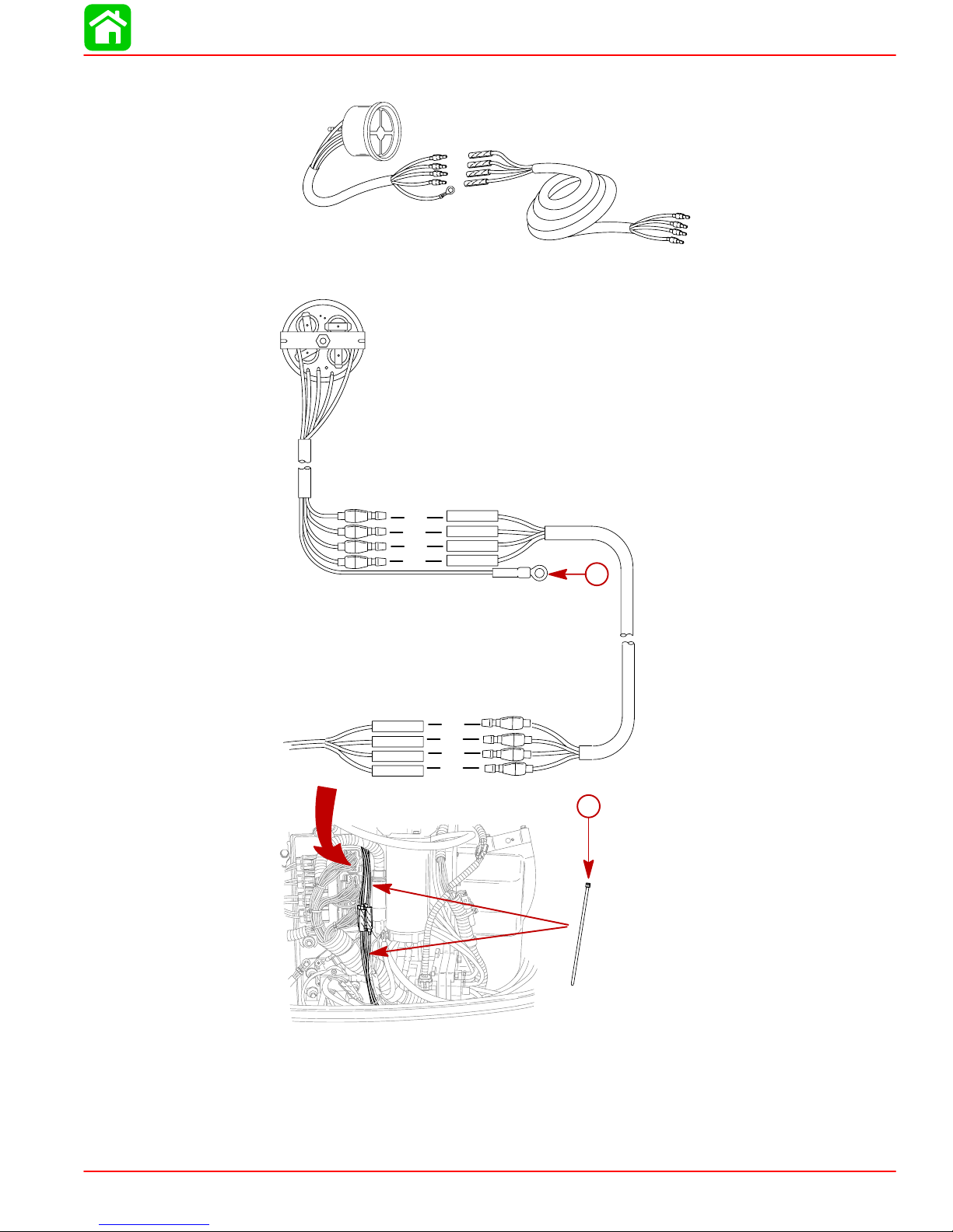
Warning Gauge Harness
Connect the harness extension to gauge and engine.
OUTBOARD MOTOR INSTALLATION
1
6
4
3
2
5
a
b
c
d
e
a
b
c
d
a-TAN/BLACK
b-TAN/WHITE
c-PINK/LT. BLUE to PINK/LT. BLUE
d-ORANGE
e-Connect PURPLE to 12 Volt Source or Adjacent Gauge
f-Sta-Straps – Fasten Wiring to Prevent Catching on Cowl
90-855347R1 JANUARY 1999 Page 1D-7
f
Page 45
OUTBOARD MOTOR INSTALLATION
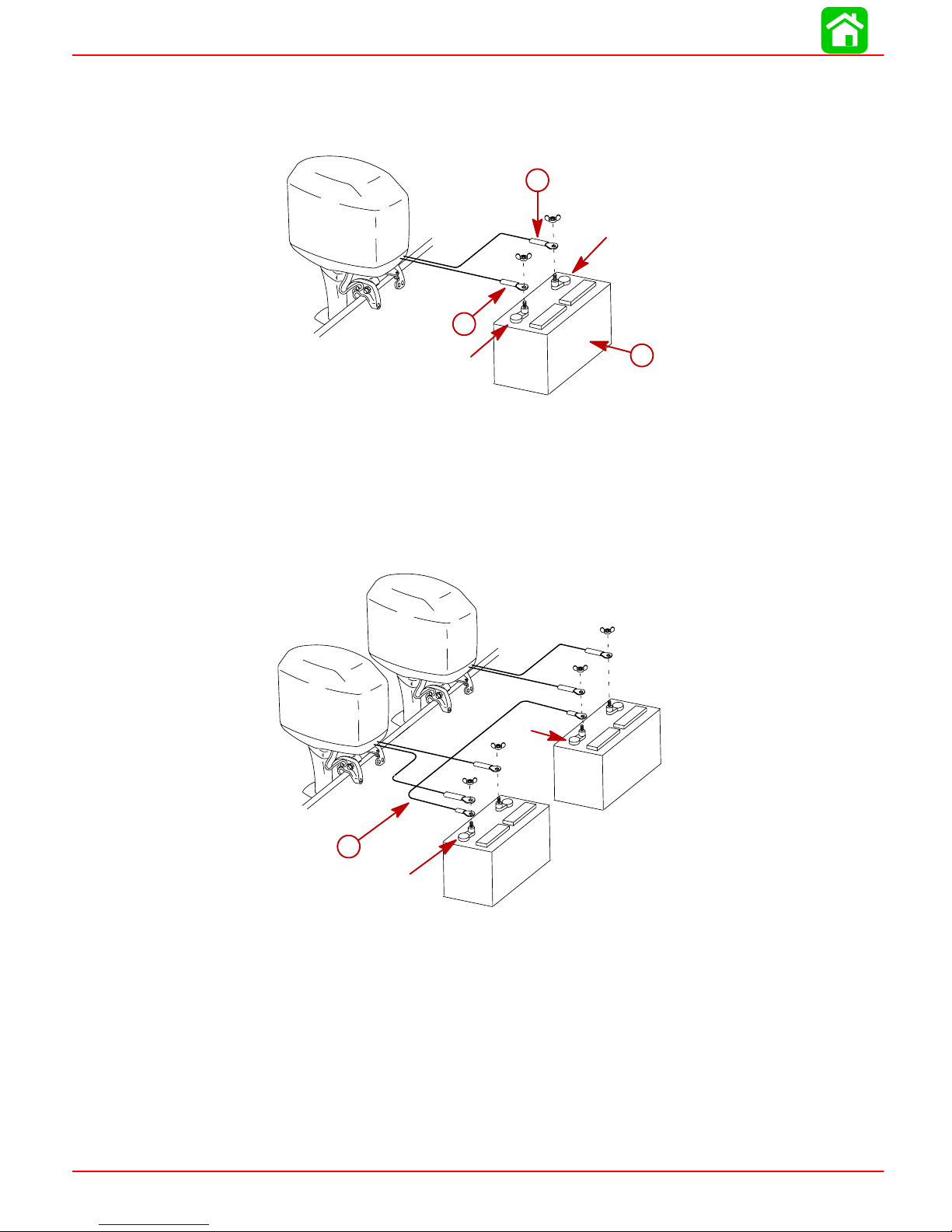
Battery Cables
Single Outboard
a
(+)
b
Dual Outboard
(–)
a-RED Sleeve (Positive)
b-BLACK Sleeve (Negative)
c-Starting Battery
Connect a common ground cable (wire size same as engine battery cables) between
NEGATIVE (–) terminals on starting batteries.
c
(–)
d-Common Ground Cable
Page 1D-8 90-855347R1 JANUARY 1999
d
(–)
Page 46
Shift Cable
Install cables into the remote control following the instructions provided with the remote
control.
NOTE: Install the shift cable to the engine first. The shift cable is the first cable to move
when the remote control handle is moved out of neutral.
COUNTER ROTATION OUTBOARDS
Counter rotating (left hand) gear cases can be identified by a “L” stamped into the end of
the propeller shaft.
The Quicksilver Dual Engine Console Mount Control, P/N 88688A22 or 88688A52, is required to shift the counter rotation outboard. The installation instructions shipped with the
control explain the procedure required to connect this control to a counter rotation outboard.
IMPORTANT: If the counter rotation outboard is rigged similar to a standard rotation outboard OR if a standard rotation outboard is rigged similar to a counter rotation outboard, the reverse gear and bearing in the gear case must function as forward gear. THE REVERSE GEAR/BEARING ARE NOT DESIGNED TO CARRY THE
SUST AINED LOADS THAT ARE GENERA TED WHEN RUNNING UNDER CONST ANT
HIGH RPM AND THRUST CONDITIONS.
OUTBOARD MOTOR INSTALLATION
OUTBOARD SHIFTING DIRECTION
On counter rotation outboards, the shift linkage moves in the opposite direction compared
to a standard rotation outboard.
STANDARD ROTATION GEAR OUTBOARDS
Forward Gear
COUNTER ROTATION OUTBOARDS
Reverse Gear
Reverse Gear
Forward Gear
90-855347R1 JANUARY 1999 Page 1D-9
Page 47
OUTBOARD MOTOR INSTALLATION
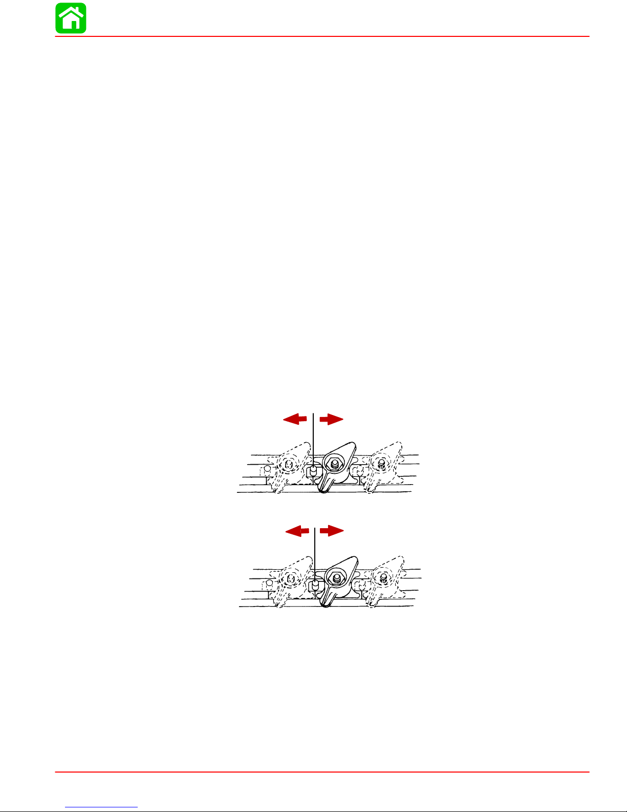
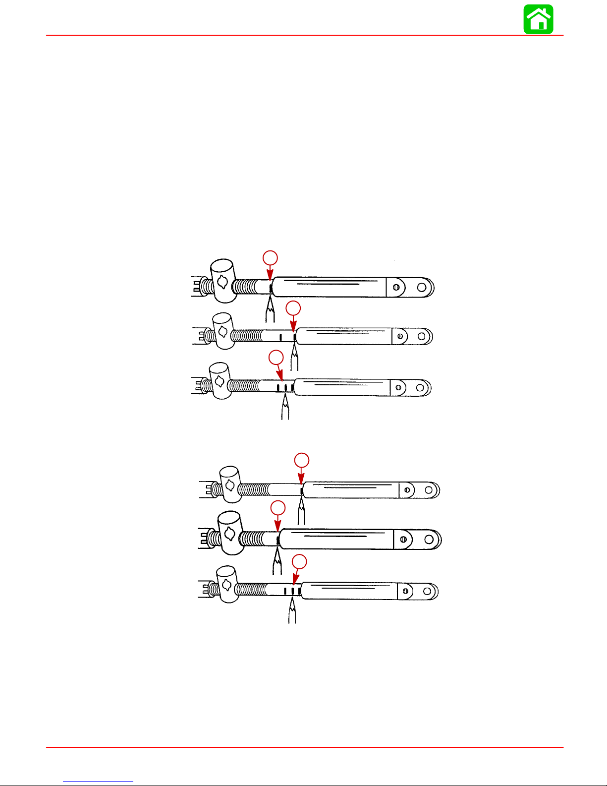
Installation
IMPORTANT: Step 1 must be followed for proper adjustment of the shift cable.
1. Locate the center point of the slack or lost motion that exists in the shift cable as follows:
a. Move the remote control handle from neutral into forward and advance the handle
to full speed position. Slowly return the handle back to the neutral. Place a mark
(a) on the cable against the cable end guide.
b. Move the remote control handle from neutral into reverse and advance the handle
to full speed position. Slowly return the handle back to the neutral. Place a mark
(b) on the cable against the cable end guide.
c. Make a center mark (c), midway between marks (“a” and “b”). Align the cable end
guide against this center mark when installing cable to the engine.
STANDARD ROTATION OUTBOARDS
a
b
COUNTER ROTATION OUTBOARDS
c
a
b
c
Page 1D-10 90-855347R1 JANUARY 1999
Page 48

OUTBOARD MOTOR INSTALLATION
2. Position remote control and outboard into neutral.
N
3. Slide the shift cable retainer forward until resistance is felt, then slide cable anchor
toward rear until resistance is felt. Center the anchor pin between resistance points.
a
b
a-Shift Cable Retainer
b-Anchor Pin
4. Align the shift cable end guide with the center mark as instructed in Step 1.
5. Place shift cable on anchor pin. Adjust cable barrel so it slips freely into the barrel
holder.
6. Secure shift cable with shift cable retainer.
b
a
a-Cable Barrel
b-Shift Cable Retainer
7. Check shift cable adjustments as follows:
a. With remote control in forward, the propshaft should lock solidly in gear. If it does
not, adjust cable barrel closer to cable end guide.
b. Shift remote control into neutral. The propshaft should turn freely without drag. If
not, adjust barrel away from cable end guide. Repeat steps a and b.
c. Shift remote control into reverse while turning propeller. The propshaft should lock
solidly in gear. If not, adjust barrel away from cable end guide. Repeat steps a thru
c.
90-855347R1 JANUARY 1999 Page 1D-11
Page 49
OUTBOARD MOTOR INSTALLATION
d. Return remote control handle to neutral. The propeller should turn freely without
drag. If not, adjust barrel closer to cable end guide. Repeat steps a thru d.
Throttle Cable
INSTALLATION
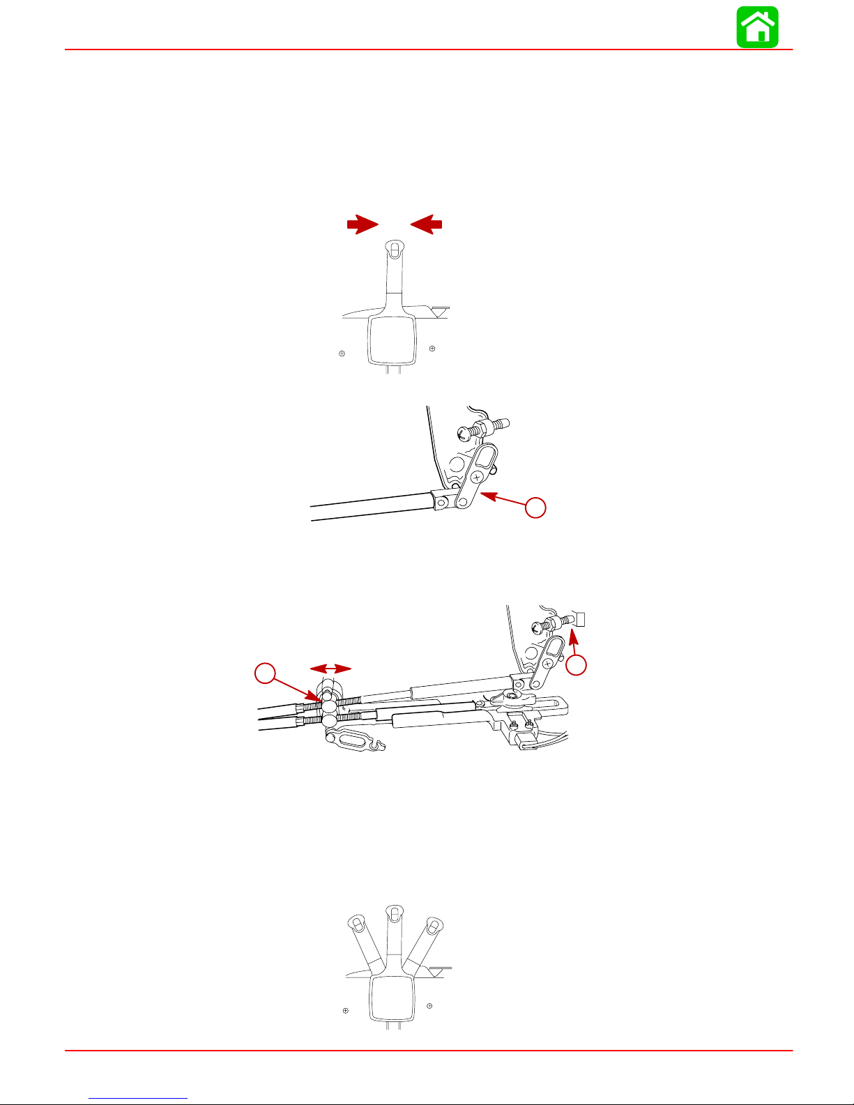
1. Position remote control into neutral.
2. Attach throttle cable to the throttle lever. Secure with latch.
N
a
a-Latch
3. Adjust the cable barrel so that the installed throttle cable will hold the idle stop screw
against the stop.
a
a-Cable Barrel – Adjust To Hold Idle Stop Screw Against Stop
b-Idle Stop Screw
4. Check throttle cable adjustment as follows:
a. Shift outboard into gear a few times to activate the throttle linkage. Make sure to
rotate the propeller shaft while shifting into reverse.
F
N
R
b
Page 1D-12 90-855347R1 JANUARY 1999
Page 50
OUTBOARD MOTOR INSTALLATION
b. Return remote control to neutral. Place a thin piece of paper between idle adjust-
ment screw and idle stop. Adjustment is correct when the paper can be removed
without tearing, but has some drag on it. Readjust cable barrel if necessary.
IMPORTANT: The idle stop screw must be touching the stop.
a-Idle Stop Screw
b-Idle Stop
5. Lock the barrel holder in place with the cable latch.
Front Clamp Reassembly
IMPORT ANT: Sufficient slack must exist in engine wiring harness, battery cables,
fuel hose, and oil hoses routed between clamp and engine attachment point, to relieve stress and prevent hoses from being kinked or pinched.
a
b
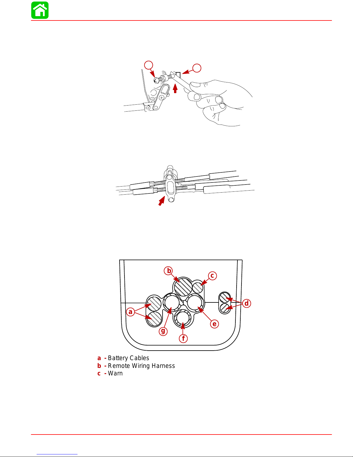
1. Place the clamp over the wiring, hoses, and control cables as shown.
b
c
d
a
e
g
f
a-Battery Cables
b-Remote Wiring Harness
c-Warning Gauge Wiring Harness
d-Control Cables
e-Oil Hose with Blue Stripe
f-Fuel Hose
g-Oil Hose
90-855347R1 JANUARY 1999 Page 1D-13
Page 51
OUTBOARD MOTOR INSTALLATION
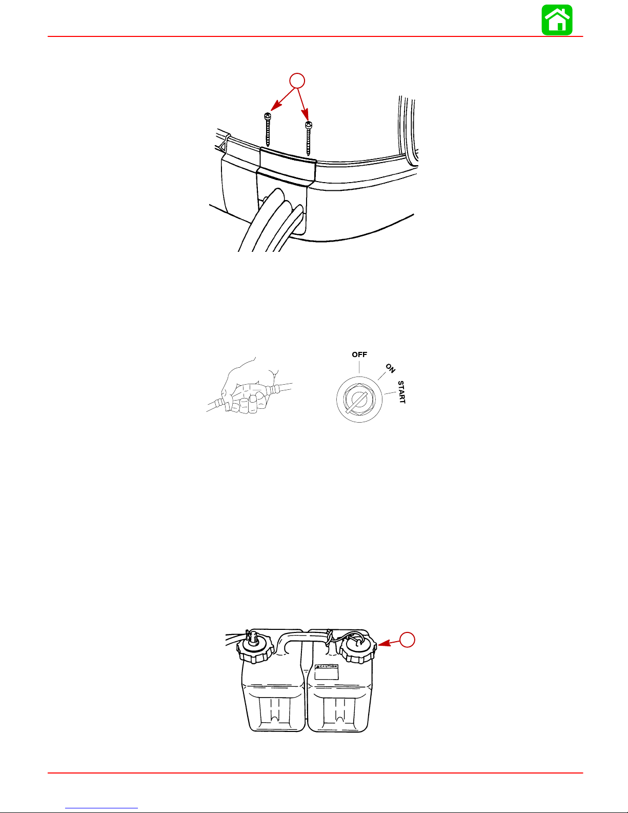
2. Fasten clamp together with two screws.
a-Screws
Filling Fuel System
NOTE: For initial start of a new engine or for an engine that ran out of fuel, or was drained
of fuel, the fuel system should to be filled as follows:
a
•
Squeeze the fuel line primer bulb until it feels firm.
•
Turn the ignition key switch to the ON position for three seconds. This operates the
electric fuel pump.
•
Turn the ignition key switch back to the OFF position, and squeeze the primer bulb
again until it feels firm. T urn the ignition key switch to the “ON” position again for three
seconds. Continue this procedure until the fuel line primer bulb stays firm.
Oil Injection Set-Up
Filling
1. Fill remote oil tank with the recommended oil listed in the Operation and Maintenance
Manual. Tighten fill cap.
a
a-Fill Cap
Page 1D-14 90-855347R1 JANUARY 1999
Page 52

2. Remove cap and fill engine oil tank with oil. Reinstall the fill cap.
a-Engine Oil Tank
b-Fill Cap
Priming the Oil Injection Pump
Before starting engine for the first time, prime the oil injection pump. Priming will re-
move any air that may be in the pump, oil supply hose, or internal passages.
a
OUTBOARD MOTOR INSTALLATION
b
a
b
a-Oil Injection Pump
b-Oil Supply Hose
CAUTION
T o prevent damage to the fuel pumps, fill the engine fuel system with fuel. Otherwise the fuel pumps will run without fuel during the priming process.
Prime the oil injection pump as follows:
1. Fill the engine fuel system with fuel. Connect fuel hose and squeeze primer bulb until
it fells firm.
2. Turn the ignition key switch to the “ON” position.
3. Within the first 10 seconds after the key switch has been turned on, move the remote
control handle from neutral into forward gear 3 to 5 times. This will automatically start
the priming process.
90-855347R1 JANUARY 1999 Page 1D-15
N
F
Page 53

OUTBOARD MOTOR INSTALLATION
NOTE: It may take a few minutes for the pump to complete the priming process.
Purging Air From the Engine Oil Tank
1. Loosen the fill cap on the engine oil tank.
2. Start the engine. Run the engine until the all the air has been vented out of the tank
and oil starts to flow out of the tank. Re-tighten fill cap.
a-Fill Cap
Trim “In” Angle Adjustment
Some outboard boats, particularly some bass boats, are built with a greater than normal
transom angle which will allow the outboard to be trimmed further “in” or “under”. This
greater trim “under” capability is desirable to improve acceleration, reduce the angle and
time spend in a bow high boat attitude during planing off, and in some cases, may be necessary to plane off a boat with aft live wells, given the variety of available propellers and
height range of engine installations.
a
However, once on plane, the engine should be trimmed to a more intermediate position
to a avoid a bow-down planing condition called “plowing”. Plowing can cause “bow steering” or “over steering” and inefficiently consumes horsepower . In this condition, if attempting a turn or encountering a diagonal, moderate wake, a more abrupt turn than intended
may result.
In rare circumstances, the owner may decide to limit the trim under. This can be accomplished by purchasing a stainless steel tilt pin (P/N 17-49930A1) and inserting it through
whatever pin hole is desired. The non-stainless steel shipping bolt should not be used in
this application other than on a temporary basis.
WARNING
Avoid possible serious injury or death. Adjust outboard to an intermediate trim
position as soon as boat is on plane to avoid possible ejection due to boat spinout. Do not attempt to turn boat when engine is trimmed extremely under or in.
a
Page 1D-16 90-855347R1 JANUARY 1999
Page 54
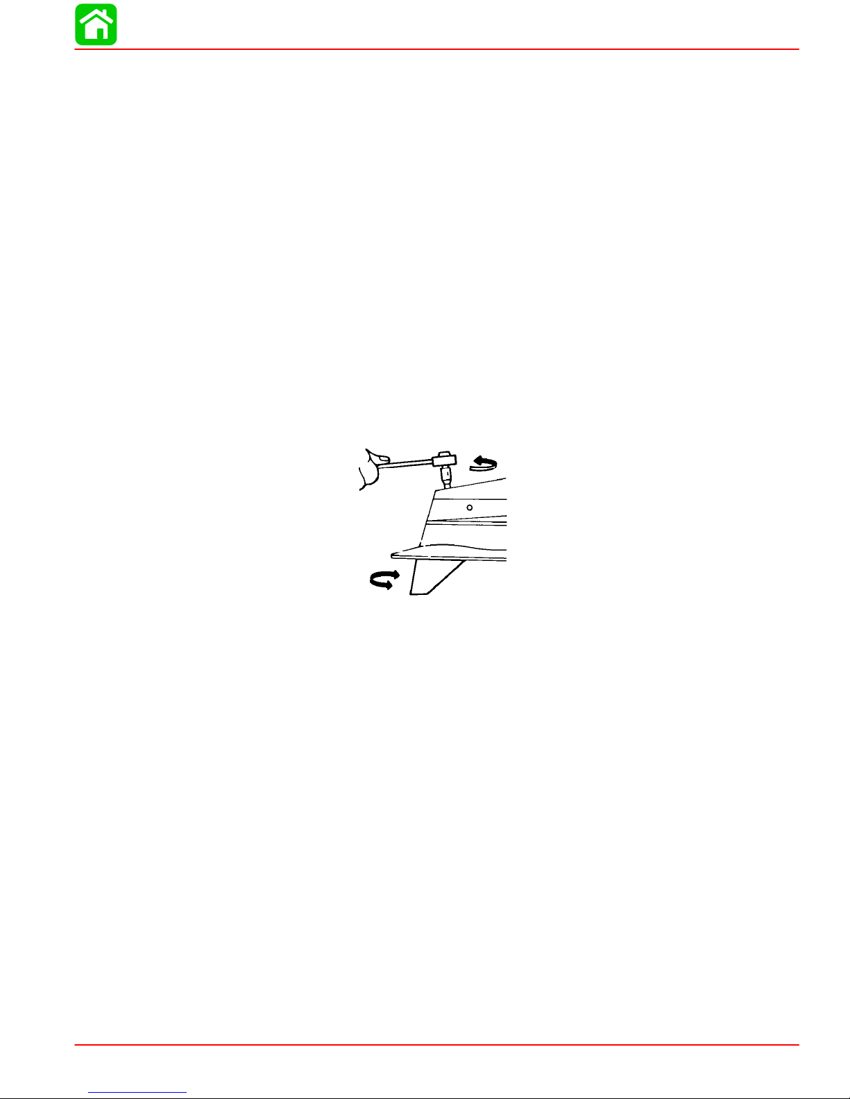
Trim Tab Adjustment
Propeller steering torque may cause your boat to pull in one direction. This steering torque
results from your outboard not being trimmed so the propeller shaft is parallel to the water
surface. The trim tab can help compensate for this steering torque and can be adjusted
within limits to reduce any unequal steering effort.
Models Without Power Steering
Operate your boat at normal cruising speed, trimmed to desired position. Turn your boat
left and right and note the direction the boat turns more easily.
If adjustment is necessary, loosen trim tab bolt until trim tab moves freely (does not rub
against locking ridges). DO NOT strike tab to make adjustments. Make small adjustments
at a time. If the boat turns more easily to the left, move the trailing edge of trim tab to the
left. If the boat turns more easily to the right move the trailing edge of trim tab to the right.
Position trim tab in one of the locating grooves BEFORE tightening bolt to prevent damage to holding mechanism. Torque bolt to 40 lb-ft (54 Nm) and retest.
Models With Power Steering
Trim tab adjustment is not required. The trailing edge of the trim tab should be set straight
back.
OUTBOARD MOTOR INSTALLATION
90-855347R1 JANUARY 1999 Page 1D-17
Page 55

Table of Contents
IGNITION
ELECTRICAL
Section 2A – Ignition
Specifications 2A-1. . . . . . . . . . . . . . . . . . . . . . . . . . . . . . . .
Special Tools 2A-2. . . . . . . . . . . . . . . . . . . . . . . . . . . . . . . .
Electrical Components 2A-4. . . . . . . . . . . . . . . . . . . . . . . .
Theory of Operation 2A-6. . . . . . . . . . . . . . . . . . . . . . . . . .
Ignition Component Description 2A-6. . . . . . . . . . . . . . . .
Electronic Control Module (ECM) 2A-6. . . . . . . . . . . .
Flywheel 2A-7. . . . . . . . . . . . . . . . . . . . . . . . . . . . . . . . .
Ignition Coils 2A-7. . . . . . . . . . . . . . . . . . . . . . . . . . . . . .
Crank Position Sensor 2A-7. . . . . . . . . . . . . . . . . . . . .
Throttle Position Sensor (TPS) 2A-7. . . . . . . . . . . . . .
Charging System Alternator 2A-7. . . . . . . . . . . . . . . . .
Temperature Sensor 2A-8. . . . . . . . . . . . . . . . . . . . . . .
Manifold Absolute Pressure (MAP) Sensor 2A-9. . .
Air Temperature Sensor 2A-9. . . . . . . . . . . . . . . . . . . .
Direct Injectors 2A-9. . . . . . . . . . . . . . . . . . . . . . . . . . . .
Fuel Injectors 2A-9. . . . . . . . . . . . . . . . . . . . . . . . . . . . .
Specifications
Ignition Coil Ohm Test
Connect meter leads between primary terminal (GRN/Striped)
and ground (BLACK) terminal pin.
Connect meter leads between spark plug wire/high voltage
tower and ground terminal pin.
Disconnecting Harness Connectors from
Ignition Coils and/or Injectors 2A-9. . . . . . . . . . . . . . .
Troubleshooting 2A-9. . . . . . . . . . . . . . . . . . . . . . . . . . .
Troubleshooting Without Digital Diagnostic
Terminal 2A-10. . . . . . . . . . . . . . . . . . . . . . . . . . . . . . . . . . .
Troubleshooting With the Digital Diagnostic
Terminal 2A-11. . . . . . . . . . . . . . . . . . . . . . . . . . . . . . . . . . .
Notes 2A-12. . . . . . . . . . . . . . . . . . . . . . . . . . . . . . . . . . . . . .
DDT Functions 2A-13. . . . . . . . . . . . . . . . . . . . . . . . . . . . . .
DFI Troubleshooting Guide 2A-15. . . . . . . . . . . . . . . . . . .
Ignition Components Removal and Installation 2A-18. .
Flywheel Cover Removal and Installation 2A-18. . . .
Electronic Control Module (ECM) 2A-19. . . . . . . . . . .
Ignition Module (Coil) 2A-20. . . . . . . . . . . . . . . . . . . . .
Crank Position Sensor 2A-21. . . . . . . . . . . . . . . . . . . .
Throttle Position Sensors (TPS) 2A-21. . . . . . . . . . . .
0.38 - 0.78
8.1 - 8.9 k
2
A
Temperature Sensor Test (Refer to Chart page 2A-8)
Temperature Sensor(s)
Between Black and each TAN/BLK wire. No Continuity
Between each lead and ground No Continuity
Direct Injector Test
Direct Injector Ohm Test (Injector Lead Disconnected)
Connect meter leads between each injector terminal pin.
Fuel Injector Test
1 - 1.6
Fuel Injector Ohm Test (Injector Lead Disconnected)
Connect meter leads between each injector terminal pin.
1.7 - 1.9
90-855347R1 JANUARY 1999 Page 2A-1
Page 56
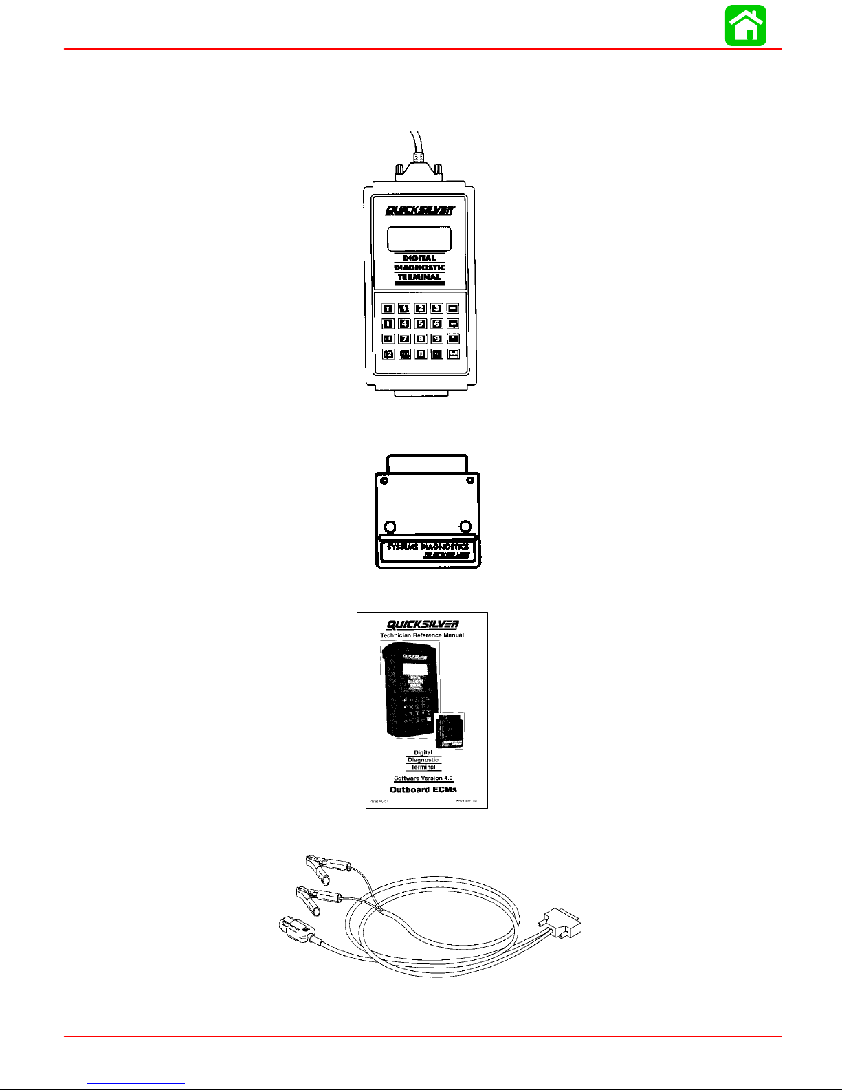
IGNITION
Special Tools
1. Digital Diagnostic Terminal (DDT) 91-823686A2
2. Software Cartridge 91-822608--5
3. DDT Reference Manual 90-825159-3
4. Adaptor Harness 84-822560A5
Page 2A-2 90-855347R1 JANUARY 1999
Page 57
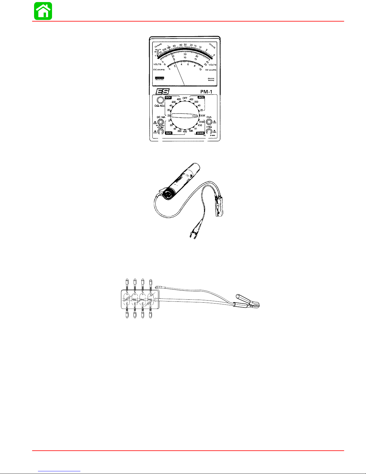
5. Multi-Meter/DVA Tester (91-99750A1)
6. Inductive Timing Light 91-99379
IGNITION
7. Spark Gap Tester 91-850439T
55117
90-855347R1 JANUARY 1999 Page 2A-3
Page 58

IGNITION
Electrical Components
10
8
9
11
12
6 Dielectric Grease (92-823506--1)
25
Liquid Neoprene (92-25711--2)
13
7
6
5
14
15
16
3
2
37
36
36
40
41
17
35
32
30
1
4
23
38
21
26
22
18
20
19
34
25
29
48
49
46
44
39
47
43
42
45
28
31
52
51
55
27
50
53
54
NOTE: COAT ALL EYELET WIRING TERMINALS WITH #25 GACO N700 (LIQUID NEOPRENE 92-25711-2)
NOTE: COA T ALL MUL TI-PIN ELECTRICAL CONNECTIONS (EXCEPT POWER TRIM RELAY CONNECT ORS)
WITH #6 DC-4 (DIELECTRIC GREASE 92-823506--1)
Page 2A-4 90-855347R1 JANUARY 1999
Page 59

IGNITION
REF
Electrical Components
.
QTY. DESCRIPTION lb-in lb-ft Nm.
NO.
1
2
3
4
5
6
7
8
9
10
11
12
13
14
15
16
17
18
19
20
21
22
23
24
25
26
27
28
29
30
31
32
33
34
35
36
37
38
39
40
41
42
43
44
45
46
47
48
49
50
51
52
53
54
55
1 ELECTRICAL MOUNTING PLATE
6 IGNITION COIL
1 HI-TENSION CABLE
6 SPARK PLUG (HEAVY DUTY) 240 20 27
6 SPACER
6 SCREW (1/4-20 x 3-1/4 IN.)
1 MAP SENSOR
2 SCREW (M6 x 14) 35 4
1 TUBING (31 IN.)
4 SCREW (.312-18 x 1-1/4 IN.) 235 19.6 26.5
4 WASHER
4 GROMMET
4 BUSHING
2 SCREW-engine harness ground (M6 x 14) 35 4
6 WASHER
6 NUT
1 TRIM HARNESS
3 RELAY
3 DECAL-Trim Relay
3 BRACKET
3 BUSHING
3 GROMMET
2 SCREW (M6 x 25) 35 4
1 SCREW (M6 x 35) 35 4
1 BUSHING
2 ST A STRAP
1 ENGINE HARNESS
1 HARNESS (SERVICE ITEM)
4 FUSE
1 BRACKET-Fuse Holder
2 SCREW (M4 x 8)
1 ECU (135)
1 ECU (150)
1 PAD
3 SCREW (M6 x 25) 70 8
6 BUSHING
3 GROMMET
2 SCREW (M6 x 14) 100 11.5
1 CLIP
1 CLAMP
2 SCREW (10-16 x 3/8 IN.)
1 SOLENOID MOUNTING PLA TE
3 SCREW (M6 x 12) 150 17
2 SCREW (M6 x 14) 35 4
1 ST AR TER SOLENOID
2 GROMMET
2 SCREW (M6 x 25) 35 4
1 CABLE (BLACK)
2 BUSHING
1 BATTERY CABLE (POSITIVE)
2 LOCKWASHER
2 NUT (5/16-18) 50 5.5
2 NUT (10-32) 8 0.9
1 CABLE
1 CAP NUT
TORQUE
90-855347R1 JANUARY 1999 Page 2A-5
Page 60

IGNITION
Theory of Operation
When the ignition key is turned to the RUN position, battery voltage is applied to the main
relay through the PURPLE wire. When the Electronic Control Module (ECM) receives a
signal from the Crank Position Sensor, the main relay ground circuit is completed through
the ECM. The main relay is then closed and D.C. current from the battery or charging system is transferred through the main relay 20 Amp fuse to the positive terminal of all 6 ignition coil primary windings. The negative terminal of the coil primary is connected to engine
ground through the Electronic Control Module (ECM). When this circuit is closed, a magnetic field is allowed to be built up in the ignition coil. The Crank Position Sensor senses
the location of the 24 teeth on the flywheel and supplies a trigger signal to the ECM. When
the ECM receives this signal, the ECM will then open the ground circuit of the coil primary .
The magnetic field in the ignition coil primary will then collapse cutting across the coil secondary winding creating a high voltage charge (50,000 volts) that is sent to the spark plug.
Ignition Component Description
Electronic Control Module (ECM)
The ECM requires 8 VDC minimum to operate. If the ECM should fail, the engine will stop
running.
The inputs to the ECM can be monitored and tested by the Digital Diagnostic Terminal
91-823686A2 using adaptor harness 84-822560A5.
The ECM performs the following functions:
• Calculates the precise fuel and ignition timing requirements based on engine speed,
throttle position, manifold pressure and coolant temperature.
• Controls fuel injectors for each cylinder, direct injectors for each cylinder and ignition
for each cylinder.
• Controls all alarm horn and warning lamp functions.
• Supplies tachometer signal to gauge.
• Controls RPM limit function.
• Monitors shift interrupt switch.
• Records engine running information.
Page 2A-6 90-855347R1 JANUARY 1999
Page 61

Flywheel
Ignition Coils
IGNITION
24 teeth under the flywheel ring gear provide engine rpm and crankshaft position information to the ECM through the crank position sensor.
Inductive type ignition coils are used on the DFI engines.
Ignition Coil Ohm Test
Connect meter leads between primary terminal (GRN/Striped)
and ground (Black) terminal pin.
Connect meter leads between spark plug wire/high voltage
tower and ground terminal pin.
Crank Position Sensor
Senses 24 teeth located on flywheel under ring gear. Supplies the ECM with crank position information and engine speed. If sensor should fail, the engine will stop running.
Throttle Position Sensor (TPS)
Two (2) Throttle Position Sensors are used in conjunction with one another . If one sensor
should fail, the dash mounted CHECK ENGINE light will light and the warning horn will
sound. RPM will be limited to 3000 rpm. If both TPS’s should fail, rpm will be reduced to
idle by the ECM. TPS settings are not adjustable. TPS settings can be monitored with the
Digital Diagnostic Terminal through the ECM.
Charging System Alternator
Battery charging system is contained within the belt driven alternator, including the regulator. At cranking speeds, electrical power for the engine is provided by the boat battery
– minimum recommended size is 750 CCA, or 1,000 MCA, cold cranking amperes. Above
550 RPM, all electrical power is provided by the alternator. Should engine rpm drop below
550 RPM, the alternator is not capable of providing sufficient output and the battery becomes the primary source of electrical power.
Alternator output (when hot) to the battery @ 2000 RPM is approximately 33 - 38 amperes.
0.38 - 0.78
8.1 - 8.9 k
90-855347R1 JANUARY 1999 Page 2A-7
Page 62

IGNITION
Temperature Sensor
Two (2) temperature sensors are used to provide cylinder head temperature information
to the ECM. One sensor is mounted in the starboard cylinder head and one in the air compressor cylinder head. The ECM uses this information to increase injector pulse width for
cold starts and to retard timing in the event of an over-heat condition.
An ohms test of the temperature sensor would be as follows:
Insert digital or analog ohmmeter test leads into both T AN/BLACK sensor leads. With en-
gine at temperature (F) indicated, ohm readings should be as indicated ±10%.
270
255
240
225
210
195
180
165
150
135
120
105
90
75
Temperature (F)
60
45
30
15
0
0 0.2 0.4 0.6 0.8 1.0 1.2 1.4 1.6 1.8 2.0 2.2 2.4 2.6 2.8 3.0 3.2
Temperature Sensor
Resistance (k)
Temperature Sensor(s)
Between Black and each TAN/BLK wire. No Continuity
Between each lead and ground No Continuity
Page 2A-8 90-855347R1 JANUARY 1999
Page 63

Manifold Absolute Pressure (MAP) Sensor
The MAP sensor is mounted between the cylinder heads. A vacuum hose connects the
map sensor to the intake manifold. The ECM regulates fuel flow, in part, based on manifold absolute pressure. Drawing a vacuum on the MAP sensor hose will create a lean fuel
condition.
Air Temperature Sensor
The air temperature sensor is mounted on the intake manifold. The ECM regulates fuel
flow, in part, based on manifold air temperature. As air temperature increases, the ECM
decreases fuel flow.
Direct Injectors
6 direct injectors (1 per cylinder) are used to inject a fuel/air mix into cylinders. Injectors
are mounted between fuel rails and cylinder heads.
Direct Injector Ohm Test (Injector Lead Disconnected)
IGNITION
Connect meter leads between each injector terminal pin.
1 - 1.6
Fuel Injectors
6 fuel injectors (1 per cylinder) are used to provide fuel from the fuel rail to the direct injectors. The fuel injectors are mounted in the fuel rail.
Fuel Injector Ohm Test (Injector Lead Disconnected)
Connect meter leads between each injector terminal pin.
1.7 - 1.9
Disconnecting Harness Connectors from Ignition Coils and/or Injectors
a
a-Wire Clip (push center down to remove)
Troubleshooting
The ECM is designed such that if a sensor fails, the ECM will compensate so that the engine does not go into an over-rich condition.
Disconnecting a sensor for troubleshooting purposes may have no noticeable effect.
90-855347R1 JANUARY 1999 Page 2A-9
54871
Page 64

IGNITION
Troubleshooting Without Digital Diagnostic Terminal
Troubleshooting without the DDT is limited to checking resistance on some of the sensors.
Typical failures usually do not involve the ECM. Connectors, set-up, and mechanical wear
are most likely at fault.
• Verify spark plug wires are securely installed (pushed in) into the coil tower.
• The engine may not run or may not run above idle with the wrong spark plugs installed.
• Swap ignition coils to see if the problem follows the coil or stays with the particular
cylinder.
NOTE: ECMs are capable of performing a cylinder misfire test to isolate problem cylinders. Once a suspect cylinder is located, an output load test on the ignition coil, fuel injector and direct injector may be initiated through use of the DDT.
• Any sensor or connection can be disconnected and reconnected while the engine is
operating without damaging the ECM. Disconnecting the crank position sensor will
stop the engine.
IMPORTANT: Any sensor that is disconnected while the engine is running will be
recorded as a Fault in the ECM Fault History . Use the DDT to view and clear the fault
history when troubleshooting/repair is completed.
• If all cylinders exhibit similar symptoms, the problem is with a sensor or harness input
to the ECM.
• If problem is speed related or intermittent, it is probably connector or contact related.
Inspect connectors for corrosion, loose wires or loose pins. Secure connector seating;
use dielectric compound 92-823506-1.
• Inspect the harness for obvious damage: pinched wires, chaffing.
• Secure grounds and all connections involving ring terminals (coat with Liquid Neo-
prene 92-25711--3).
• Check fuel pump terminals.
• Check fuel pump pressure.
• Check air compressor pressure.
Page 2A-10 90-855347R1 JANUARY 1999
Page 65

Troubleshooting with the Digital Diagnostic Terminal
a
IGNITION
b
a-Digital Diagnostic Terminal (91-823686A2)
b-Software Cartridge (91-822608--4 or --5)
c-DDT Reference Manual (90-825159-3)
d-Adapter Harness (84-822560A5)
The Quicksilver Digital Diagnostic Terminal (DDT) has been developed specifically to
help technicians diagnose and repair Mercury Marine 2 and 4 cycle engines.
Attach the diagnostic cable to the ECM diagnostic connector and plug in the software cartridge. Y ou will be able to monitor sensors and ECM data values including status switches.
The ECM program can help diagnose intermittent engine problems. It will record the state
of the engine sensors and switches for a period of time and then can be played back to
review the recorded information.
c
d
Refer to the Digital Diagnostic T erminal Reference Manual for complete diagnostic procedures.
90-855347R1 JANUARY 1999 Page 2A-1 1
Page 66

IGNITION
Notes:
Page 2A-12 90-855347R1 JANUARY 1999
Page 67

IGNITION
Page 2A-13
90-855347R1 JANUARY 1999
DDT Functions – Optimax Models
Software Version 4.0 and 4.1
Select Status:
1 - IGNITION
2 - INJECTOR
3 - PUMP
4 - SENSORS
5 - SWITCHES
6 - MISCELLANEOUS
7 - RPM LIMIT
8 - BREAK-IN
MARINE DIAGNOSTICS
1 - Mariner/Mercury
2 - MerCruiser
3 - Injector Test
4 - Tool Setup
SELECT ECM
1 - 3.0L Ignition ECM
2 - 3.0L Fuel ECM
3 - 824003 Fuel ECM
4 - 2.5L Hi Perf ECM
5 - DFI ECM
6 - 4 Stroke ECM
Select Function:
1 - AUTO SELF TEST
2 - MANUAL TEST
Select Function:
1 - DATA MONITOR
2 - STATUS SWITCHES
3 - SYSTEM INFO
4 - HISTORY
5 - SPECIAL FUNCTIONS
Select Auto Test:
1 - STATIC TEST
2 - RUNNING TEST
ENGINE RPM
TPI 1 VOLTS
TPI 2 VOLTS
BATTERY VOLTS
PWR 1 VOLTS
PWR 2 VOLTS
COOL TMP STB °F
COOL TMP PRT °F
MAP PSI
AIR TMP °
TRIGGER ERR
TIME TO OIL
OIL INJ CNT
TPI %
AIR COM TMP °F
BLOCK PSI
Select Function:
1 - FAULT HISTORY
2 - RUN HISTORY
3 - CLEAR FAULT HIST
4 - CLEAR RUN HIST
Select Function:
1 - OIL PUMP PRIME
2 - CYLINDER MISFIRE
3 - OUTPUT LOAD TEST
4 - RESET BREAK-IN OIL
98 DI
ECM #
CODE
IGN PRI .38-.78 ohm
SEC 8.1-8.9 Kohm
DINJ 1.0-1.6 ohm
FINJ 1.7-1.9 ohm
TPI1 3.7-4.9v IDLE
0.3-1.8v WOT
TPI2 0.1-1.5v IDLE
3.2-4.9v WOT
TPI1 LtBlu/Red IN
TPI2 LtBlu/Wht OUT
TGAP 0.025-.04in
PWR RLY 81-99 ohm
CTS max 220F
ACT max 150-220F
30-8000 ohm 1K@77F
AIR TMP .540-44
BATV 12.6-15.0
MAP 7-15 psi
FUEL 88-90 psi
AIR 77-81 psi
Text Book Data
(specs)
Monitors Engine Functions
While Engine is Running
SWITCH ACTIVE HIST
SHIFT SW ON NA
H2O FUEL NO NO
L OIL NO NO
PUMP ACTIVE HIST
OIL PMP PASS PASS
LIMIT ACTIVE HIST
CTS LIM OFF ON
CTP LIM OFF OFF
ACT LIM OFF OFF
TP1 LIM OFF OFF
TP2 LIM OFF OFF
RPM LIM OFF OFF
OIL LIM OFF ON
BAT LIM OFF OFF
BLK LIM OFF OFF
PWR LIM OFF OFF
STATUS BREAK-IN ENGINE IS IN
BREAK-IN MODE. xxx MINUTES
TO COMPLETION.
STATUS BREAK-IN ENGINE HAS
COMPLETED A FACTORY SCHEDULED BREAK-IN.
or
MISC. ACTIVE HIST
BATTERY PASS PASS
PWR RLY PASS PASS
PWR 1 V PASS PASS
PWR 2 V PASS PASS
HORN PASS PASS
LAMP PASS PASS
SENSOR ACTIVE HIST
COOL STB PASS PASS
COOL PRT PASS PASS
MAP PASS PASS
AIR TMP PASS PASS
TPI 1 PASS PASS
TPI 2 PASS PASS
TRIG SIG PASS PASS
COMP TMP PASS PASS
BLOCK PSI PASS PASS
INJECTOR ACTIVE HIST
INJ 1 PASS PASS
INJ 2 PASS PASS
INJ 3 PASS PASS
INJ 4 PASS PASS
INJ 5 PASS PASS
INJ 6 PASS PASS
IGN ACTIVE HIST
IGN 1 PASS PASS
IGN 2 PASS PASS
IGN 3 PASS PASS
IGN 4 PASS PASS
IGN 5 PASS PASS
IGN 6 PASS PASS
Engine Not Running During Test
Engine Running During Test
Select Fault Hist:
1-IGNITION
2-INJECTOR
3-PUMP
4-SENSORS
5-SWITCHES
6-MISCELLANEOUS
RPM 3000-3999 xx
RPM 4000-4999 xx
RPM 5000-5999 xx
RPM 6000+ xx
BREAK IN Min xx
OVER TMP Sec x
RPM LIMIT CNT x
RPM LIMIT SEC x
ACT TEMP SEC x
BLOCK PSI Sec x
CTS TMP Sec x
CTP TMP Sec x
OIL PMP Sec x
ECM RUN TIME xx
RPM 0000-0999 xx
RPM 1000-1499 xx
RPM 1500-2999 xx
1
2
3
4
5
6
7
8
Any fault in Select Status functions 1 thru 7 will turn
on the matching panel light.
*Illuminated panel light 8 Indicates engine is in Break-in.
*Key switch has to be ON for all Tests.
*Engine has to be running for Tests 1,2,3, and 7.
NOTE:Test data is lost when Key Switch is turned off.
Any existing faults from Tests 1 thru 6 are transferred
to Fault History.
1 or 2
1
5
Select Load Test:
1 - IGNITION
2 - FUEL INJECTOR
3 - DIRECT INJECTOR
4 - OIL PUMP
5 - FUEL PUMP
6 - HORN
7 - LAMPS
8 - TACHOMETER
9 - MAIN POWER RELAY
Page 68

DFI Troubleshooting Guide
Symptom Cause Action
IGNITION
1. Engine cranks but won’t
start
1.0 Lanyard stop switch in wrong
Reset lanyard stop switch.
position.
1.1 Weak battery or bad starter
motor, battery voltage drops
below 8 volts while cranking
(ECM cuts out below 8 volts)
Replace/charge battery.
Inspect condition of starter motor.
Check condition of battery terminals and cables.
(Fuel pump requires 9 Volts).
1.2 Low air pressure in rail (less
than 70 psi at cranking
Inspect air system for leaks.
Inspect air filter for plugging (air
pressure measured on port rail).
Inspect air compressor reed valves
if necessary.
1.3 No fuel Check that primer bulb is firm.
Key-on engine to verify that fuel
pump runs for 2 seconds and then
turn off. Measure fuel pressure
(valve on starboard rail). Fuel pressure should be 10 ± 1 psi greater
than the air pressure.
1.4 Low fuel pressure Check fuel pressure from low pres-
sure electric fuel pump (6–10 psi).
Check for fuel leaks. If fuel pressure leaks down faster than air
pressure, seals on fuel pump may
be leaking. Check air system pressure, see 1.2.
1.5 Sheared Flywheel Key Remove flywheel and inspect key.
1.6 Blown fuse Replace fuse. Inspect engine har-
ness and electrical components.
1.7 Main Power Relay not
functioning
Listen for relay to “click” when the
key switch is turned on.
1.8 Spark Plugs Remove fuel pump fuse.
Unplug all direct injector connectors.
Remove spark plugs from each
cylinder.
Connect spark plug leads to Spark
Gap Tester 91-830230T.
Crank engine or use DDT output
load test for each ignition coil and
observe spark. If no spark is present, replace appropriate ignition
coil. If spark is present, replace
spark plugs.
90-855347R1 JANUARY 1999 Page 2A-15
Page 69

IGNITION
DFI Troubleshooting Guide (continued)
Symptom Cause Action
1. Engine cranks but will not
start (continued)
1.9 ECM not functioning Injection System:
Listen for injector “ticking” when
cranking or connect spare injector
to each respective harness. Ticking should start after 2 cranking
revolutions.
Ignition System:
– Check for proper operation by
using Inductive Timing Light
91-99379.
– Check battery voltage
(RED/YEL Lead) @ ignition
coils.
– Check for blown fuse (C15).
– Check battery voltage to fuse
from main power relay
(PURPLE Lead).
– Check for shorted stop wire
(BLK/YEL).
– Check crank position sensor
setting [0.015 in. – 0.040 in.
(0.38mm – 1.01mm)] from
flywheel or for defective crank
position sensor.
– Defective ECM.
2. Engine cranks, starts and
stalls
Power Supply:
Clean and inspect remote control
male and female harness connectors.
2.0 Low air pressure in rail See 1.2
2.1 Low fuel pressure in rail See 1.2 and 1.3
2.2 Abnormally high friction in
engine
Check for scuffed piston or other
sources of high friction.
2.3 Air in fuel system/lines See 1.3 Crank and start engine
several times to purge.
2.4 TPS malfunction Check motion of throttle arm. Stop
nuts should contact block at idle
and WOT. Check TPS set-up. Must
connect DDT with adapter harness
(84-822560A5) to ECM.
2.5 Remote control to engine
harness connection is poor
Clean and inspect male and female connectors.
Page 2A-16 90-855347R1 JANUARY 1999
Page 70

DFI Troubleshooting Guide (continued)
Symptom Cause Action
IGNITION
3. Engine idle is rough 3.1 Low air pressure in rail (less
than 79 ± 2 psi while running)
3.2 Fouled spark plug Replace spark plug:
3.3 Failed direct injector Refer to specifications for ohm
3.4 Failed fuel injector Refer to specifications for ohm
3.5 Bad coil/weak spark Refer to specifications for ohm
3.6 Flywheel key sheared Remove flywheel and inspect key.
4. Engine idles fast (RPM
>700) or surges
4.1 Broken fuel pressure regulator
or tracker diaphragm
4.2 Fuel leak Check for fuel entering induction
See 1.2
–If carbon bridges electrode gap
or if it is completely black.
–If it is not firing and is wet with
fuel.
Note: If spark plug is grey or completely black with aluminum specs,
this indicates a scuffed piston.
test.
test.
test.
Measure fuel pressure. Remove
and inspect diaphragms (a special
tool is required for assembly).
manifold or air compressor inlet.
Fuel pump diaphragm leaking and/
or Vapor Separator flooding over.
5. Engine runs rough below
3000 rpm
6. Engine runs rough above
3000 rpm
4.3 Tracker Valve spring missing Inspect tracker valve for proper as-
sembly.
4.4 Improper set-up Check throttle cable & cam roller
adjustment.
5.1 Fouled spark plug See 3.2
5.2 Low air pressure in rail See 1.2
5.3 Throttle misadjusted Check throttle cam setup on induc-
tion manifold. Inspect linkage and
roller.
If throttle plate stop screws have
been tampered with, contact Mercury Marine Service Department
for correct adjustment procedures.
5.4 Bad coil/weak spark See 3.5
5.5 TPS malfunction See 2.4
6.1 Fouled spark plug See 3.2
6.2 Speed Reduction See 7
6.3 Low air pressure in rails See 1.2
90-855347R1 JANUARY 1999 Page 2A-17
6.4 TPS malfunction See 2.4
Page 71
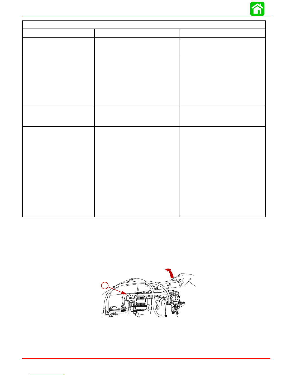
IGNITION
DFI Troubleshooting Guide (continued)
Symptom Cause Action
7. Speed Reduction (RPM
reduced or limited to 3000)
8. Engine RPM reduced to
idle only
9. Loss of spark on 1 cylinder
7.1 Low battery voltage
ECM requires 8 volts minimum
Fuel Pump requires 9 volts
7.2 Overheat condition (engine
and/or air compressor)
7.3 Oil pump electrical failure Check electrical connection.
7.4 TPS failure
If one (1) TPS fails rpm is
reduced to 3,000. If both TPSs
fail, rpm is reduced to idle
8.1 Both TPSs failed
8.2 Battery voltage below 9.5 volts
9.1 Loose wire or pin in connectors
between ECM and coil primary.
9.2 Faulty ignition coil.
9.3 Faulty spark plug.
9.4 Faulty spark plug wire
Note: Due to the long spark dura-
tion of this ignition system, the
DDT may indicate the incorrect cylinder as having an ignition fault.
Example: If the DDT indicates an
ignition fault on cylinder #4, the
problem may be on the prior cylinder in the firing order – I.E. cylinder
number #3.
Check battery and/or alternator.
Check electrical connections.
Check water pump impeller/cooling
system.
Check electrical connections.
See 2.4
Use DDT or volt meter to check
battery voltage
Check connectors.
Replace coil.
Replace spark plug.
Replace spark plug wire.
Ignition Components Removal and Installation
Flywheel Cover Removal and Installation
REMOVAL
Remove flywheel cover by lifting off. Disconnect the vent hose.
a
a-Vent Hose
INSTALLATION
Install flywheel cover as follows:
a. Place cover onto the front flange.
Page 2A-18 90-855347R1 JANUARY 1999
Page 72

b. Push rear of the cover down onto the rear pin and air intake tube for the air com-
pressor.
c. Connect vent hose onto fitting.
d. Position hoses into holder.
c
a
a-Front Flange
b-Air Intake Tube
c-Fitting
d-Holder
Electronic Control Module (ECM)
REMOVAL
IGNITION
d
b
1. Disconnect ECM harness connectors.
2. Remove 3 bolts securing ECM.
d
d
a-Electronic Control Module
b-Bracket – Fuse Holder
c-Rubber Pad
d-Bolt (2) – Torque to 80 lb-in (9 N·m).
e-Bolt (3) – Torque to 80 lb-in (9 N·m)
f-Bushing
g-Rubber Grommet
f
f
f
e
e
c
c
b
b
f
g
g
a
a
INSTALLATION
1. Secure ECM to powerhead with 3 bolts.
2. Install rubber pad and bracket for the fuse holder.
3. Reconnect harness connectors.
90-855347R1 JANUARY 1999 Page 2A-19
Page 73
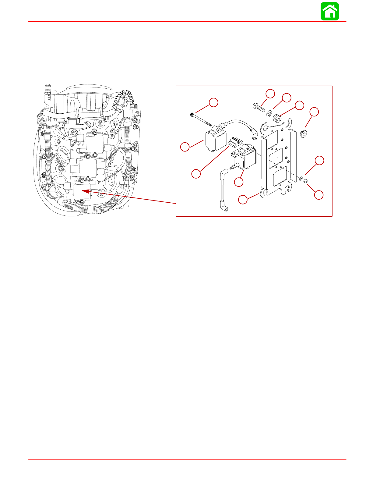
IGNITION
Ignition Module (Coil)
REMOVAL
1. Disconnect coil harness and spark plug lead.
2. Loosen the electrical mounting plate to gain access to the rear locknuts.
3. Remove module attaching bolts.
e
e
f
a
a
b
b
c
c
b
b
f
g
g
h
h
i
i
INSTALLATION
56141
a-Bolts (6) –Torque to 80 lb-in (9 Nm).
b-Ignition Coils (6)
c-Spacer – Place on Bolts between coils
d-Electrical Mounting Plate
e-Bolts (4) – Torque to 235 lb-in (27 Nm).
f-Washer
g-Rubber Grommet
h-Bushing
i-Washer
j-Locknut (6)
1. Fasten coils to electrical mounting plate as shown.
2. Reinstall electrical mounting plate.
3. Reconnect spark plug lead and coil harness.
j
d
d
j
Page 2A-20 90-855347R1 JANUARY 1999
Page 74

Crank Position Sensor
REMOVAL
1. Disconnect harness.
2. Remove bolt securing sensor to bracket.
a-Shim (0.010 or 0.020 in.) (0.254 mm 0.508 mm)
b-Crank Position Sensor
c-Washer
d-Bolt – Torque to 50 lb-in (5.5 Nm)
INSTALLATION
1. Fasten sensor to bracket with bolt.
IGNITION
a
b
c
d
56069
2. Set air gap @ 0.025 in. – 0.040 in. (0.635 mm – 1.01 mm)
3. Reconnect sensor harness.
Throttle Position Sensors (TPS)
REMOVAL
1. Disconnect wiring harness.
2. Remove screws securing sensors to bracket.
e
e
d
d
c
c
b
b
a
a
a-Throttle Sensor – Inside
b-Spacer
c-TPS Lever
d-Throttle Sensor – Outside
e-Screw (3) – Torque to 20 lb-in (2.5 Nm).
INSTALLATION
1. Fasten sensors to bracket as shown.
2. Reconnect wiring harness.
90-855347R1 JANUARY 1999 Page 2A-21
Page 75

Section 2B – Charging & Starting System
Table of Contents
CHARGING & STARTING SYSTEM
ELECTRICAL
Specifications 2B-1. . . . . . . . . . . . . . . . . . . . . . . . . . . . . . . .
Battery Cable Size 2B-2. . . . . . . . . . . . . . . . . . . . . . . . . . .
Replacement Parts 2B-2. . . . . . . . . . . . . . . . . . . . . . . . . . .
Recommended Battery 2B-2. . . . . . . . . . . . . . . . . . . . . . . .
Special Tools 2B-3. . . . . . . . . . . . . . . . . . . . . . . . . . . . . . . .
Battery 2B-3. . . . . . . . . . . . . . . . . . . . . . . . . . . . . . . . . . . . . .
Precautions 2B-3. . . . . . . . . . . . . . . . . . . . . . . . . . . . . . .
Charging a Discharged Battery 2B-4. . . . . . . . . . . . . . . . .
Winter Storage of Batteries 2B-4. . . . . . . . . . . . . . . . . . . .
Flywheel Removal and Installation 2B-5. . . . . . . . . . . . . .
Removal 2B-5. . . . . . . . . . . . . . . . . . . . . . . . . . . . . . . . .
Installation 2B-6. . . . . . . . . . . . . . . . . . . . . . . . . . . . . . . .
Flywheel/Alternator 2B-8. . . . . . . . . . . . . . . . . . . . . . . . . . .
System Components 2B-10. . . . . . . . . . . . . . . . . . . . . . . .
Precautions 2B-10. . . . . . . . . . . . . . . . . . . . . . . . . . . . . .
Alternator Description 2B-11. . . . . . . . . . . . . . . . . . . . . . . .
Diagnosis of Alternator System on Engine 2B-11. . . . . .
Alternator Assembly 2B-12. . . . . . . . . . . . . . . . . . . . . .
Alternator System Circuitry Test 2B-13. . . . . . . . . . . . . . .
Output Circuit 2B-13. . . . . . . . . . . . . . . . . . . . . . . . . . . .
Sensing Circuit 2B-13. . . . . . . . . . . . . . . . . . . . . . . . . . .
Voltage Output 2B-14. . . . . . . . . . . . . . . . . . . . . . . . . . .
Current Output 2B-15. . . . . . . . . . . . . . . . . . . . . . . . . . .
Repair 2B-15. . . . . . . . . . . . . . . . . . . . . . . . . . . . . . . . . . . . .
Removal 2B-15. . . . . . . . . . . . . . . . . . . . . . . . . . . . . . . .
Disassembly and Test 2B-16. . . . . . . . . . . . . . . . . . . . .
Rotor Test 2B-18. . . . . . . . . . . . . . . . . . . . . . . . . . . . . . .
Stator Test 2B-19. . . . . . . . . . . . . . . . . . . . . . . . . . . . . . .
Reassembly 2B-20. . . . . . . . . . . . . . . . . . . . . . . . . . . . . . . .
Pulley 2B-21. . . . . . . . . . . . . . . . . . . . . . . . . . . . . . . . . . .
Installation 2B-22. . . . . . . . . . . . . . . . . . . . . . . . . . . . . . . . .
Alternator Belt Tension Adjustment 2B-22. . . . . . . . . . . .
Starter System 2B-23. . . . . . . . . . . . . . . . . . . . . . . . . . . . . .
Starter Motor Amperes Draw 2B-23. . . . . . . . . . . . . . .
Starter System Components 2B-23. . . . . . . . . . . . . . .
Description 2B-23. . . . . . . . . . . . . . . . . . . . . . . . . . . . . .
Starter Motor 2B-24. . . . . . . . . . . . . . . . . . . . . . . . . . . . . . .
Troubleshooting the Starter Circuit 2B-25. . . . . . . . . . . . .
Starter Circuit Troubleshooting Flow Chart 2B-26. . . . . .
Starter Removal and Installation 2B-27. . . . . . . . . . . . . . .
Removal 2B-27. . . . . . . . . . . . . . . . . . . . . . . . . . . . . . . .
Installation 2B-28. . . . . . . . . . . . . . . . . . . . . . . . . . . . . . .
Disassembly 2B-28. . . . . . . . . . . . . . . . . . . . . . . . . . . . .
Starter Cleaning, Inspection and Testing 2B-30. . . . . . .
Cleaning and Inspection 2B-30. . . . . . . . . . . . . . . . . . .
T esting 2B-30. . . . . . . . . . . . . . . . . . . . . . . . . . . . . . . . . .
Starter Reassembly 2B-32. . . . . . . . . . . . . . . . . . . . . . . . .
Starter Solenoid Test 2B-34. . . . . . . . . . . . . . . . . . . . . .
Commander 2000 Key Switch Test 2B-35. . . . . . . . . . . .
2
B
Specifications
CHARGING
SYSTEM
STARTING
SYSTEM
Alternator Output (Regulated)
Brush Length
Voltage Output
Regulator Current Draw
Electric Start – All Models
Starter Draw (Under Load)
Starter Draw (No Load)
Minimum Brush Length
Battery Rating
32 - 38 Amperes @ 2000 RPM @ Battery
52 - 60 Amperes @ 2000 RPM @
Alternator
Std Exposed Length: 0.413 in. (10.5 mm)
Min. Exposed Length: 0.059 in. (1.5 mm)
13.5 to 15.1 Volts
0.15 mA (Ign. Switch Off)
30.0 mA (Ign. Switch On)
165 Amperes
30 Amperes
0.25 in. (65.4 mm)
1000 (Minimum) Marine Cranking Amps
(MCA)
750 (Minimum) Cold Cranking Amps
(CCA)
90-855347R1 JANUARY 1999 Page 2B-1
Page 76

CHARGING & STARTING SYSTEM
Battery Cable Size
If standard (original) battery cables are replaced with longer cables, the wire gauge size must increase. See
chart below for correct wire gauge size.
Wire Gage Size
Battery Cable Length
Battery Cable Wire Gage Size
Mercury/Mariner Outboards
Battery Cable Length
8 ft.
9 ft.
10ft.
1 1ft.
12ft.
13ft.
14ft.
15ft.
16ft.
17ft.
18ft.
19ft.
20ft.
21ft.
22ft.
23ft.
2.4m
2.7m
3.0m
3.4m
3.7m
4.0m
4.3m
4.6m
4.9m
5.2m
5.5m
5.8m
6.1m
6.4m
6.7m
7.0m
Models Wire Gage Size No. SAE
6-25 Hp
30-1 15Hp#6* #4 #4 #4 #4 #4 #2 #2 #2 #2 #2 #2 #2 #2 #0 #0 #0
#8* #8 #6 #6 #6 #6 #4 #4 #4 #4 #4 #4 #4 #4 #2 #2 #2
24ft.
7.3m
125-250
Hp (ex-
cept DFI)
DFI
Models
* = Standard (original) Cable Length and wire gage size.
#6* #6 #4 #4 #4 #4 #4 #4 #2 #2 #2 #2 #2 #2 #2
#4* #2 #2 #2 #2 #2 #2 #2 #2 #2 #0 #0 #0
Replacement Parts
Electrical, ignition and fuel system components on your Mercury/Mariner outboard are designed and manufactured to comply with U. S. Coast Guard Rules
and Regulations to minimize risks of fire and explosions. Use of replacement
electrical, ignition or fuel system components, which do not comply with these
rules and regulations, could result in a fire or explosion hazard and should be
avoided.
Recommended Battery
A 12 volt marine battery with a minimum Cold Cranking amperage rating of 750 amperes
or 1000 (minimum) Marine Cranking amperes should be used.
WARNING
Page 2B-2 90-855347R1 JANUARY 1999
Page 77

Special Tools
1. Volt/Ohm Meter 91-99750A1or DMT 2000 Digital Tachometer Multimeter
CHARGING & STARTING SYSTEM
91-854009A1
a
a-Volt/Ohm Meter 91-99750A1
b-DMT 2000 Digital Tachometer Multimeter 91-854009A1
2. Ammeter (60 Ampere minimum) (Obtain locally)
3. Flywheel Holder 91-52344
4. Protector Cap 91-24161
5. Flywheel Puller 91-73687A1
b
54964
Battery
Precautions
If battery acid comes in contact with skin or eyes, wash skin immediately with a
mild soap. Flush eyes with water immediately and see a doctor.
When charging batteries, an explosive gas mixture forms in each cell. Part of this gas escapes through holes in vent plugs and may form an explosive atmosphere around battery
if ventilation is poor. This explosive gas may remain in or around battery for several hours
after it has been charged. Sparks or flames can ignite this gas and cause an internal explosion which may shatter the battery.
The following precautions should be observed to prevent an explosion.
90-855347R1 JANUARY 1999 Page 2B-3
CAUTION
Page 78

CHARGING & STARTING SYSTEM
1. DO NOT smoke near batteries being charged or which have been charged very
recently.
2. DO NOT break live circuits at terminals of batteries because a spark usually occurs
at the point where a live circuit is broken. Always be careful when connecting or disconnecting cable clamps on chargers. Poor connections are a common cause of electrical arcs which cause explosions.
3. DO NOT reverse polarity of battery terminal to cable connections.
Charging a Discharged Battery
Hydrogen and oxygen gases are produced during normal battery operation or
charging. Sparks or flame can cause this mixture to ignite and explode, if they are
brought near the vent openings. Sulphuric acid in battery can cause serious
burns, if spilled on skin or in eyes. Flush or wash away immediately with clear water.
The following basic rule applies to any battery charging situation:
1. Any battery may be charged at any rate (in amperes) or as long as spewing of electrolyte (from violent gassing) does not occur and for as long as electrolyte temperature
does not exceed 125° F (52° C). If spewing of electrolyte occurs, or if electrolyte temperature exceeds 125° F, charging rate (in amperes) must be reduced or temporarily
halted to avoid damage to the battery.
WARNING
2. Battery is fully charged when, over a 2-hour period at a low charging rate (in amperes),
all cells are gassing freely (not spewing liquid electrolyte), and no change in specific
gravity occurs. Full charge specific gravity is 1.260-1.275, corrected for electrolyte
temperature with electrolyte level at 3/16 in. (4.8 mm) over plate, unless electrolyte
loss has occurred (from age or over-filling) in which case specific gravity reading will
be lower. For most satisfactory charging, lower charging rates in amperes are recommended.
3. If, after prolonged charging, specific gravity of at least 1.230 on all cells cannot be
reached, battery is not in optimum condition and will not provide optimum performance; however, it may continue to provide additional service, if it has performed satisfactorily in the past.
4. T o check battery voltage while cranking engine with electric starting motor , place RED
(+) lead of tester on POSITIVE (+) battery terminal and BLACK (–) lead of tester on
NEGA TIVE (–) battery terminal. If the voltage drops below 9-1/2 volts while cranking,
the battery is weak and should be recharged or replaced.
Winter Storage of Batteries
Battery companies are not responsible for battery damage either in winter storage or in
dealer stock if the following instructions are not observed:
1. Remove battery from its installation as soon as possible and remove all grease, sulfate and dirt from top surface by running water over top of battery . Be sure, however ,
that vent caps are tight beforehand, and blow off all excess water thoroughly with compressed air. Check water level, making sure that plates are covered.
Page 2B-4 90-855347R1 JANUARY 1999
Page 79

2. When adding distilled water to battery , be extremely careful not to fill more than 3/16
in. (4.8 mm) above perforated baffles inside battery . Battery solution or electrolyte expands from heat caused by charging. Overfilling battery will cause electrolyte to overflow (if filled beyond 3/16″ above baffles).
3. Grease terminal bolts well with 2-4-C Marine Lubricant and store battery in a COOLDRY place. Remove battery from storage every 30-45 days, check water level and
put on charge for 5 or 6 hours at 6 amperes. DO NOT FAST CHARGE.
4. If specific gravity drops below 1.240, check battery for reason and recharge. When
gravity reaches 1.260, discontinue charging. T o check specific gravity , use a hydrometer, which can be purchased locally.
5. Repeat preceding charging procedure every 30-45 days, as long as battery is in storage, for best possible maintenance during inactive periods to ensure a good serviceable battery in spring. When ready to place battery back in service, remove excess
grease from terminals (a small amount is desirable on terminals at all times), recharge
again as necessary and reinstall battery.
Flywheel Removal and Installation
Removal
CHARGING & STARTING SYSTEM
1. Remove flywheel cover from engine.
WARNING
Engine could possibly start when turning flywheel during removal and installation; therefore, disconnect (and isolate) spark plug leads from spark plugs to prevent engine from starting.
2. Disconnect spark plug leads from spark plugs.
3. While holding flywheel with flywheel holder (91-52344), remove flywheel nut and
washer.
a
a-Flywheel Holder (91-25344)
4. Install a crankshaft Protector Cap (91-24161) on end of crankshaft, then install Flywheel Puller (91-73687A2) into flywheel.
90-855347R1 JANUARY 1999 Page 2B-5
57415
Page 80
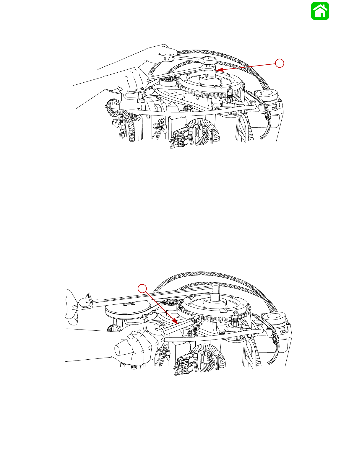
CHARGING & STARTING SYSTEM
5. Hold flywheel tool with wrench while tightening bolt down on protector cap. Tighten
bolt until flywheel comes free.
a-Flywheel Puller (91-73687A2)
NOTE: Neither heat or hammer should be used on flywheel to aid in removal as damage
to flywheel or electrical components under flywheel may result.
a
57413
Installation
6. Remove flywheel. Inspect flywheel for cracks or damage.
IMPORTANT: Do not apply grease to the flywheel taper or corresponding crankshaft splines. The application of grease to these areas will result in flywheel hub
breakage when tightening flywheel nut.
1. Install flywheel.
2. Install flywheel washer and nut.
3. Hold flywheel with Flywheel Holder (91-52344). Torque nut to 125 lb-ft (169.5 Nm).
a
a-Flywheel Holder (91-52344)
Page 2B-6 90-855347R1 JANUARY 1999
57414
Page 81

Notes:
CHARGING & STARTING SYSTEM
90-855347R1 JANUARY 1999 Page 2B-7
Page 82
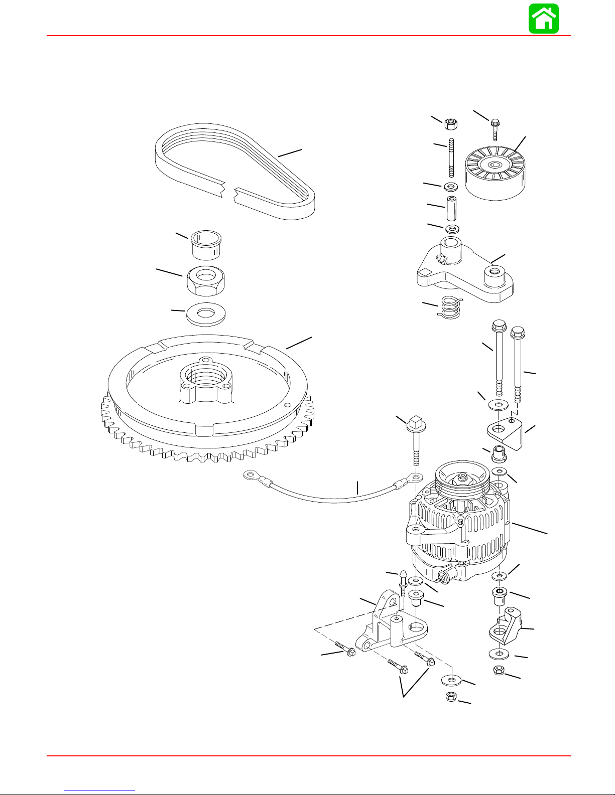
CHARGING & STARTING SYSTEM
Flywheel/Alternator
25
26
27
18
23
24
17
20
19
20
15
22
21
16
3
2
4
14
13
11
12
10
14
6
5
7
1
7
7
5
4
9
5
8
4
9
Page 2B-8 90-855347R1 JANUARY 1999
Page 83

CHARGING & STARTING SYSTEM
REF
Flywheel/Alternator
.
QTY. DESCRIPTION lb-in lb-ft Nm.
NO.
1 1 ALTERNATOR
2 1 SCREW (M10 x 100) 480 40 54
3 1 SCREW (M10 x120) 275 23 31
4 3 WASHER
5 3 MOUNT
6 1 BRACKET
7 3 WASHER
8 1 BRACKET
9 2 NUT 275 23 31
10 1 SCREW (M10 x 55) 275 23 31
11 1 CABLE
12 1 PIN
13 1 BRACKET
14 3 SCREW (5/16-18 x 1 IN.) 185 15.5 21
15 1 SPRING
16 1 BELT TENSIONER
17 1 STUD (M10 x 85)
18 1 NUT 180 15 20
19 1 BUSHING
20 2 WASHER
21 1 PULLEY
22 1 SCREW (M10 x 35) 300 25 34
23 1 BELT
24 1 FLYWHEEL
25 1 NUT 125 169
26 1 WASHER
27 1 PLUG
TORQUE
90-855347R1 JANUARY 1999 Page 2B-9
Page 84
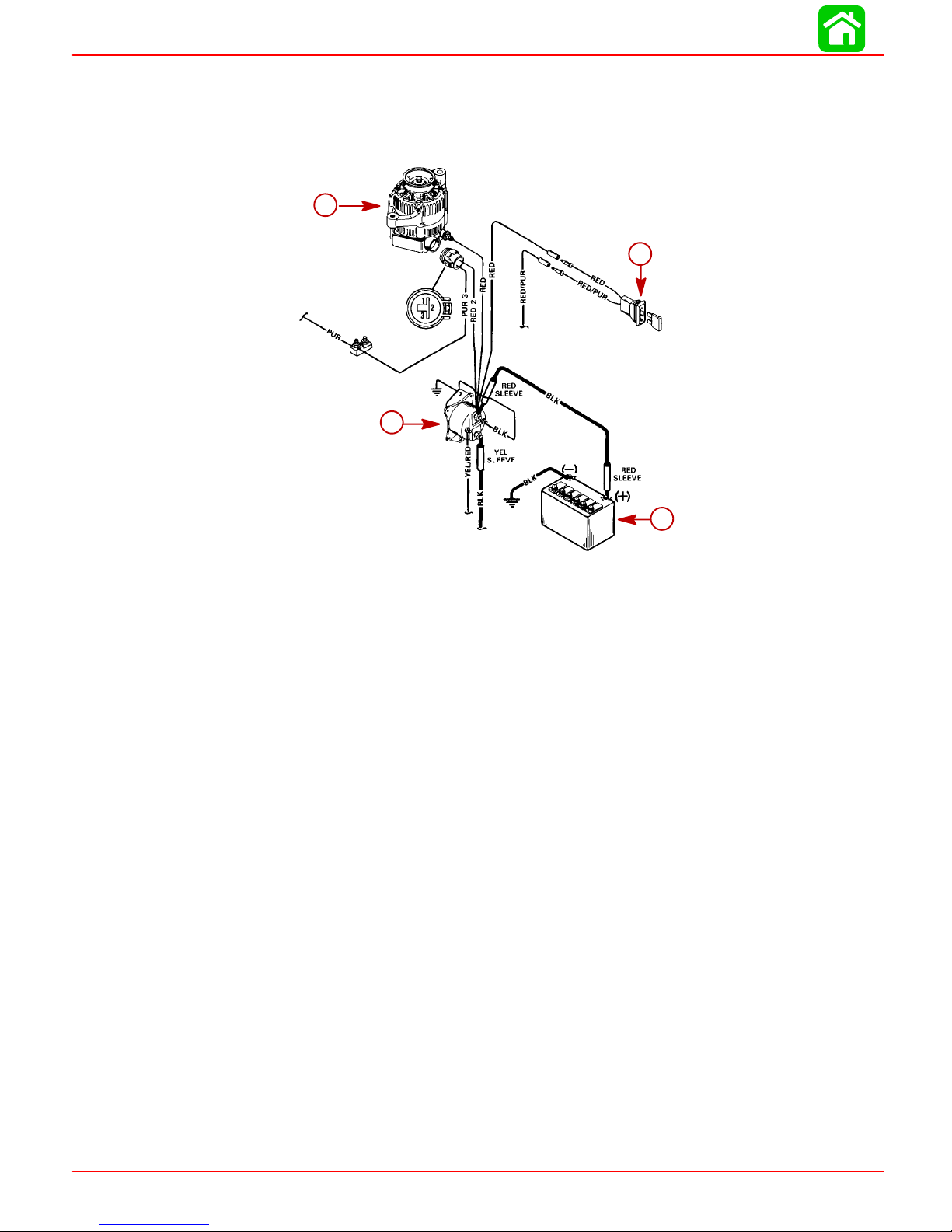
CHARGING & STARTING SYSTEM
System Components
The battery charging system consists of the alternator, battery, ignition switch, starter
solenoid and the wiring which connects these components.
a
a
c
c
d
d
Precautions
b
To
a-Alternator
b-Battery
c-20 Ampere Fuse
d-Starter Solenoid
The following precautions must be observed when working on the alternator system. Failure to observe these precautions may result in serious damage to the alternator system.
1. Do not attempt to polarize the alternator.
2. Do not short across or ground any of the terminals on the alternator, except as specifically instructed.
3. Never disconnect the alternator output lead, regulator harness or battery cables when
the alternator is being driven by the engine.
4. Always remove NEGA TIVE (–) battery cable from battery before working on alternator
system.
5. When installing battery , be sure to connect the NEGA TIVE (–) (GROUNDED) battery
cable to NEGA TIVE (–) battery terminal and the POSITIVE (+) battery cable to POSITIVE (+) battery terminal.
b
51708
6. When using a charger or booster battery, connect it in parallel with existing battery
(POSITIVE to POSITIVE; NEGATIVE to NEGATIVE).
Page 2B-10 90-855347R1 JANUARY 1999
Page 85

Alternator Description
The alternator employs a rotor, which is supported in 2 end frames by ball bearings, and
is driven at 2.5 times engine speed. The rotor contains a field winding enclosed between
2 multiple-finger pole pieces. The ends of the field winding are connected to 2 brushes
which make continuous sliding contact with the slip rings. The current (flowing through
the field winding) creates a magnetic field that causes the adjacent fingers of the pole
pieces to become alternate north and south magnetic poles.
A 3-phase stator is mounted directly over the rotor pole pieces and between the 2 end
frames. It consists of 3 windings wound 120° electrically out-of-phase on the inside of a
laminated core. The windings are connected together on one end, while the other ends
are connected to a full-wave rectifier bridge.
The rectifier bridge contains 8 diodes which allows current to flow from ground, through
the stator and to the output terminal, but not in the opposite direction.
When current is supplied to the rotor field winding, and the rotor is turned, the movement
of the magnetic fields created induces an alternating current into the stator windings. The
rectifier bridge changes this alternating current to direct current which appears at the output terminal. A diode trio is connected to the stator windings to supply current to the regulator and the rotor field during operation.
CHARGING & STARTING SYSTEM
Voltage output of the alternator is controlled by a transistorized voltage regulator that
senses the voltage at the battery and regulates the field current to maintain alternator voltage for properly charging the battery . Current output of the alternator does not require regulation, as maximum current output is self-limited by the design of the alternator. As long
as the voltage is regulated within the prescribed limits, the alternator cannot produce excessive current. A cutout relay in the voltage regulator also is not required, as the rectifier
diodes prevent the battery from discharging back through the stator.
A small amount of current is supplied by the excitation circuit in the regulator to the rotor
field to initially start the alternator charging. Once the alternator begins to produce output,
field current is supplied solely by the diode trio.
The alternator is equipped with 2 fans which induce air flow through the alternator to remove heat created by the rectifier and stator.
Diagnosis of Alternator System on Engine
1. If problem is an undercharged battery , verify condition has not been caused by excessive accessory current draw or by accessories which have accidentally been left on.
2. Check physical condition and state of charge of battery . Battery must be at least 75%
(1.230 specific gravity) of fully charged to obtain valid results in the following tests. If
not, charge battery before testing system.
3. Inspect entire alternator system wiring for defects. Check all connections for tightness
and cleanliness, particularly battery cable clamps and battery terminals.
IMPORTANT: RED output lead from alternator must be tight. A darkened RED
sleeve indicates lead was loose and becoming hot.
4. Check alternator drive belt for cracks and fraying. Replace if necessary. Check belt
tension. Adjust if necessary , as outlined under “Drive Belt Replacement and Adjust-
ment.”
90-855347R1 JANUARY 1999 Page 2B-1 1
Page 86

CHARGING & STARTING SYSTEM
Alternator Assembly
j
j
g
g
f
f
i
i
e
h
h
e
d
d
a-Pulley Nut
b-Pulley
c-Spacer
d-Frame and Rotor Assembly
e-Brush Holder
f-Brush Cover
g-Regulator
h-Rectifier (Diode Assembly)
i-Insulator
j-End Cover
c
c
b
b
a
a
51683
Page 2B-12 90-855347R1 JANUARY 1999
Page 87
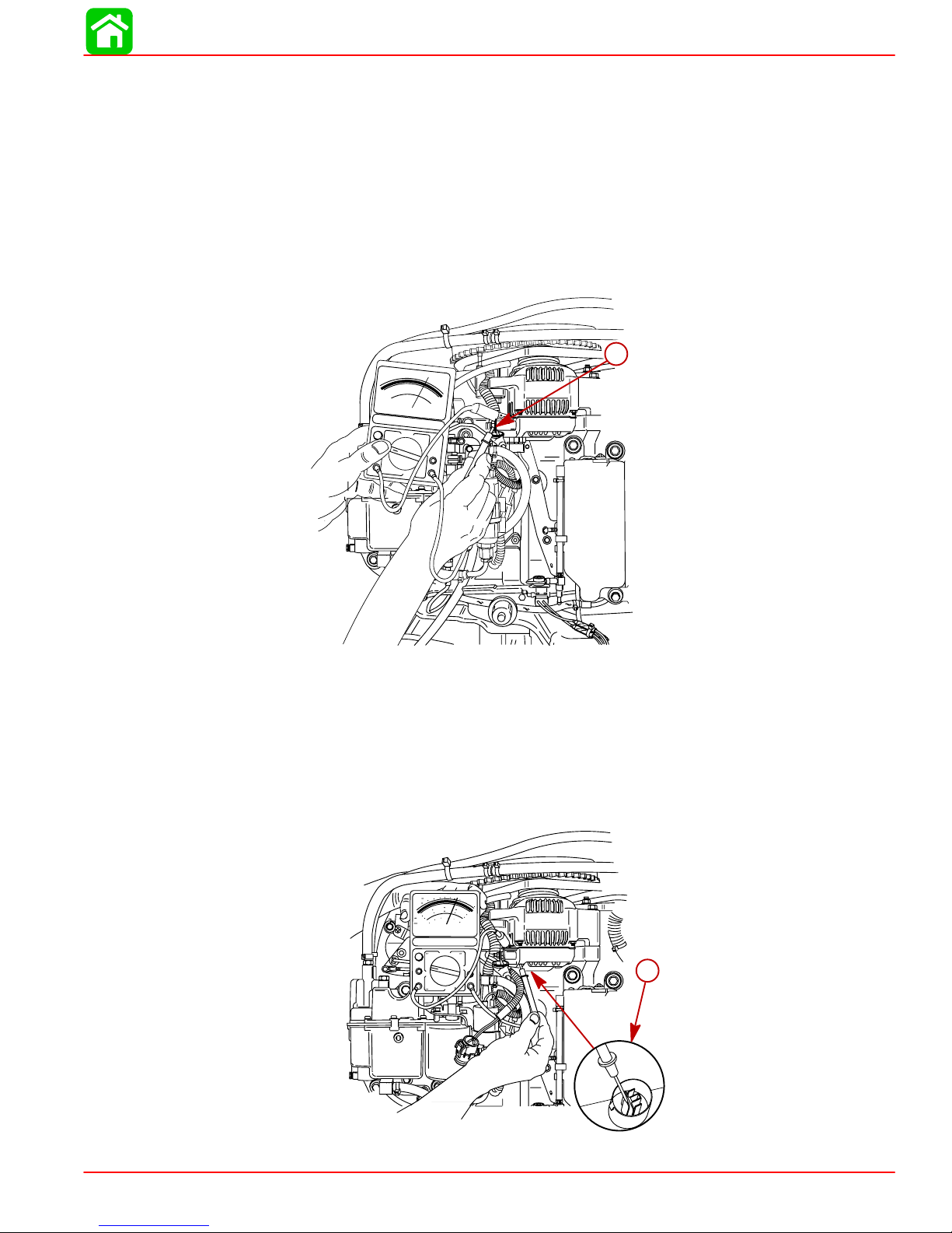
Alternator System Circuitry Test
Using a 0-20 volt DC voltmeter, perform the following tests:
Output Circuit
1. Connect POSITIVE (+) voltmeter lead to alternator terminal B (output terminal). Connect NEGATIVE (–) lead to case ground on alternator.
2. Shake alternator wiring harness. Meter should indicate battery voltage and should not
vary. If proper reading is not obtained, check for loose or dirty connections or damaged wiring.
20
30
15
40
10
60
5
OHMS
0
100
200
30
102010
15
40
5
20
6
0
8
4
0
2
10
VOLTS
0
DC AMPS
DCV
ACV
DVA
CHARGING & STARTING SYSTEM
a
a
Sensing Circuit
1. Unplug RED and PURPLE lead connector from alternator.
2. Connect POSITIVE (+) voltmeter lead to RED lead and NEGA TIVE (–) voltmeter lead
3. Voltmeter should indicate battery voltage. If correct voltage is not present, check
56113
a-Terminal B
to ground.
sensing circuit (RED lead) for loose or dirty connections or damaged wiring.
a
a
a-Sense Lead (RED)
90-855347R1 JANUARY 1999 Page 2B-13
56114
Page 88
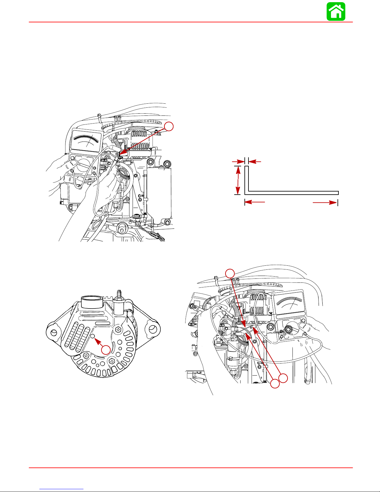
CHARGING & STARTING SYSTEM
Voltage Output
1. Using a 0-20 volt DC voltmeter, connect POSITIVE (+) lead of voltmeter to TERMINAL
B of alternator and NEGATIVE (–) lead of voltmeter to engine ground.
2. Start engine and allow to warm up. Increase engine RPM from idle to 2000. Normal
voltage output should be 13.5 – 15.1 volts. If voltage reading is greater than normal,
replace voltage regulator.
3. If voltage reading is less than normal, fabricate a tool from a piece of stiff wire to the
following specifications:
20
30
15
10
40
60
5
OHMS
100
0
40
200
30
102010
15
5
20
10
DVA
DCV
468
2
VOLTS
0
DC AMPS
ACV
0
0
a
a
0.060 in. (1.52 mm)
13/16 in. (20.6 mm)
8 in. (203 mm)
56113
a-Terminal B
4. Insert bent end of tool through end cover and ground TERMINAL F.
b
b
152030
40
60
OHMS
100
200
20
30
10
10
15
5
6
8
4
0
0
2
VOLTS
0
DC AMPS
ACV
a
a
51683
a
a
c
c
DCV
10
5
0
40
20
10
DVA
56115
a-Terminal F
b-Tool
c-Jumper Wire to Engine Ground (Attach to end of Tool)
5. With TERMINAL F grounded, voltage should rise to within the normal range (13.5 –
15.1). If voltage rises, replace the regulator.
6. If the voltage DOES NOT rise to within the normal range with TERMINAL F grounded,
perform “CURRENT OUTPUT” test.
Page 2B-14 90-855347R1 JANUARY 1999
Page 89

Current Output
1. With engine shut off, install ammeter (capable of reading 60+ amperes) in series be-
2. Start engine and allow to warm up. Advance RPM to 2000.
3. Insert tool, previously fabricated for VOLTAGE OUTPUT, through end cover and
CHARGING & STARTING SYSTEM
tween TERMINAL B on alternator and POSITIVE (+) terminal of battery.
ground TERMINAL F.
c
d
a
Repair
Removal
b
a-Terminal F
b-Tool
c-Jumper Wire to Engine Ground
d-Terminal B
e-Ammeter
4. Normal output is 60 amperes @ 2000 RPM. If output is normal, replace regulator. If
output is low, a disassembly of the alternator is necessary to inspect and test individual components.
1. Remove top cowling.
2. Disconnect battery cables from battery.
3. Disconnect wiring harness from alternator.
4. Remove pivot bolt and tension bolt.
e
a
a
56116
a-Attaching Bolt
b-Harnesses
90-855347R1 JANUARY 1999 Page 2B-15
b
a
a
b
56117
Page 90

CHARGING & STARTING SYSTEM
Disassembly and Test
1. Remove 3 screws and nut securing end cover and remove insulator and cover.
2. Remove 5 screws securing regulator and brush assembly.
c
c
d
d
b
b
g
e
a
g
b
f
a
a
a-Cover
b-Screws
c-Nut
d-Insulator
e-Regulator
f-Brush Assembly
g-Screws
51683
NOTE: Proper regulator operation can be determined by VOL T AGE OUTPUT and CURRENT OUTPUT, previous. If regulator does not meet specifications, replace regulator.
Torque regulator screws to 17 lb-in (2 Nm).
NOTE: Brushes are replaced as an assembly . Inspect assembly for stuck brushes or ex-
cessive brush wear. Normal exposed brush length is 0.156 in. (4.0 mm). Minimum exposed brush length is 0.059 in. (1.5 mm).
3. Remove 4 screws securing rectifier (diode assembly) to alternator.
51680
a-Screws
b-Rectifier (Diode Assembly)
Page 2B-16 90-855347R1 JANUARY 1999
a
b
b
51684
Page 91

CHARGING & STARTING SYSTEM
NOTE: T o test rectifier assembly , touch POSITIVE (+) lead from ohmmeter to POSITIVE
stud and NEGATIVE (–) lead from ohmmeter to each diode terminal. The ohmmeter
should indicate continuity.
a
a
c
c
a-Positive Stud
b-Positive Ohm Lead
c-Negative Ohm Lead
Reverse leads – NEGA TIVE lead on POSITIVE stud and POSITIVE lead on each diode
assembly . NO CONTINUITY should be observed. If continuity is observed in both tests,
or NO CONTINUITY is observed in both tests, the rectifier assembly is defective and must
be replaced. Torque rectifier screws to 17 lb-in (1.9 Nm).
b
b
51679
b
b
a-Positive Stud
b-Negative Ohm Lead
c-Positive Ohm Lead
IMPORTANT: Depending on the polarity of the ohmmeter, reversed readings may
be obtained – I.E. – CONTINUITY is observed when the NEGA TIVE lead touches the
POSITIVE stud and NO CONTINUITY is observed when the POSITIVE lead touches
the POSITIVE stud.
90-855347R1 JANUARY 1999 Page 2B-17
c
c
a
a
51679
Page 92
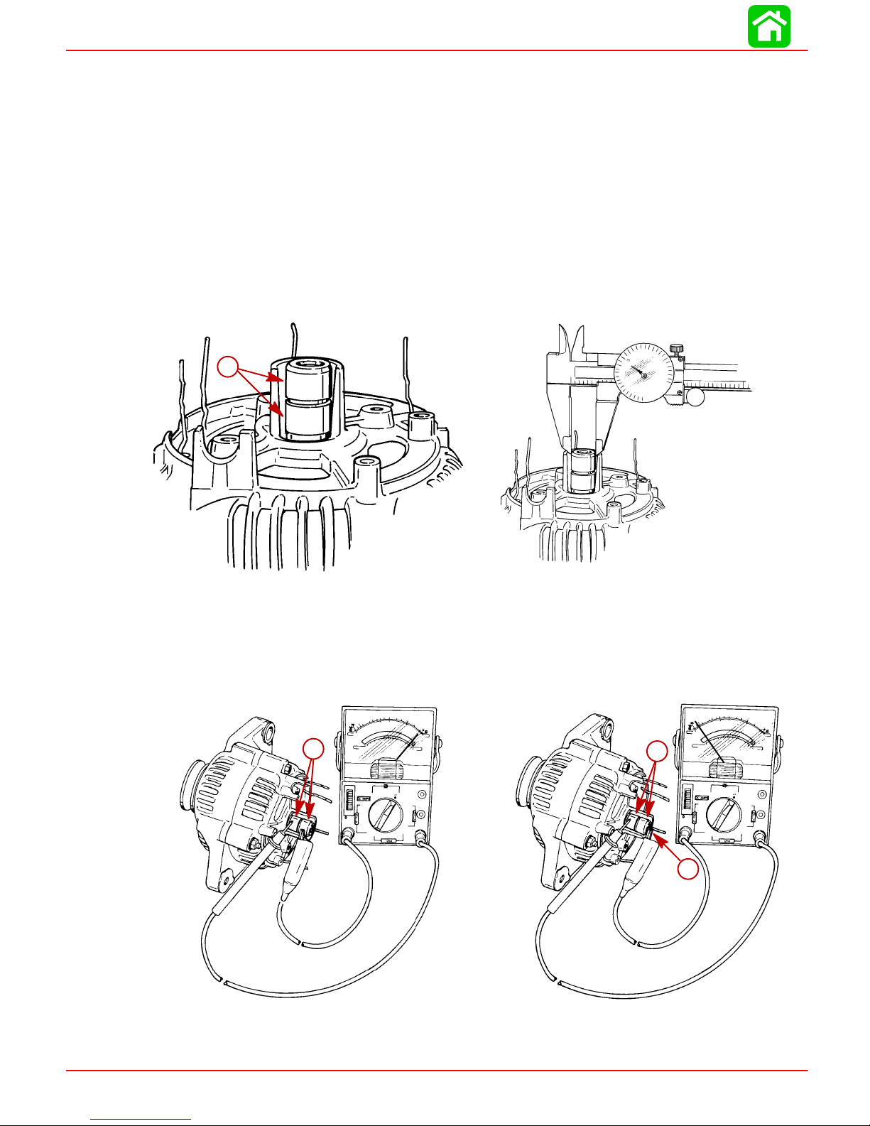
CHARGING & STARTING SYSTEM
IMPORT ANT : The regulator , rectifier and brush assembly are the only components
individually replaceable on this alternator. If the rotor or stator is defective, the entire rotor, stator and housing must be replaced as an assembly.
IMPORT ANT: Clean anti-corrosion paint from electrical connections prior to reassembly. Coat all electrical connections with LIQUID NEOPRENE (92-25711-1).
Rotor Test
1. Inspect slip ring surface for roughness, abnormal wear and/or burning. If such conditions exist, rotor is not considered serviceable and alternator should be replaced.
2. Measure the outer diameter of the slip rings using vernier calipers. STANDARD DIAMETER: 0.567 in. (14.4 mm); MINIMUM DIAMETER: 0.551 in. (14 mm). If slip ring
diameter is less than minimum, rotor is not considered serviceable and alternator
should be replaced.
a
a
51684
51680
a-Slip Rings
3. Inspect rotor for an open circuit. Using an ohmmeter, check for continuity between slip
rings. Resistance should not exceed 3 ohms. If no continuity exists, rotor is defective.
4. Check rotor for short to ground. NO CONTINUITY should exist between slip rings and
rotor shaft. If CONTINUITY exists, rotor is defective.
a
a
a
a
b
b
a-Slip Rings
b-Rotor Shaft
Page 2B-18 90-855347R1 JANUARY 1999
51682
51683
Page 93

Stator Test
CHARGING & STARTING SYSTEM
1. With rectifier removed, use an ohmmeter to check for a short circuit between each
stator lead and the stator frame. If CONTINUITY exists, stator is defective.
a
b
b
a
51682
a-Stator Leads
b-Frame
2. Inspect stator for open circuit. Using an ohmmeter, check for an open circuit between
each of the stator leads. If no continuity exists, stator is defective.
a
a
a
a
a-Stator Leads
90-855347R1 JANUARY 1999 Page 2B-19
51682
Page 94

CHARGING & STARTING SYSTEM
Reassembly
1. Position rectifier assembly over stator leads.
2. Form stator leads in a clockwise loop and secure leads to rectifier with 4 screws.
Torque screws to 17 lb-in (1.9 Nm).
b
b
a-Rectifier Assembly
b-Stator Leads
c-Stator Leads
d-Screws [Torque to 17 lb-in (1.9 Nm)]
a
a
c
a
c
a
b
b
d
51683
b
d
b
51684
3. Secure regulator to alternator with 2 screws [1 in. (25.4 mm) long]; 1 screw [0.25 in.
(6.4 mm) long] and lockwashers. DO NOT tighten screws at this time.
4. Secure brush assembly with 2 screws – [0.25 in. (6.4 mm) long] and [0.312 in. (8.0
mm) long].
c
f
e
b
c
c
a
a
a-Regulator
b-Screws [1 in. (25.4 mm)]
c-Screw [0.25 in. (6.4 mm)]
d-Brush Assembly
e-Screw [0.25 in. (6.4 mm)]
f-Screw [0.312 in. (8.0 mm)]
b
51684
d
a
51680
Page 2B-20 90-855347R1 JANUARY 1999
Page 95

CHARGING & STARTING SYSTEM
5. Install end cover. Secure cover with 3 screws. Torque screws to 23 lb-in. (2.5 Nm).
Install terminal insulator. Torque nut to 36 lb-in (4 Nm).
d
d
c
c
b
b
a
a
51683
a-Cover
b-Screw [Torque to 23 lb-in (2.5 Nm)]
c-Terminal Insulator
d-Nut [Torque to 36 lb-in. (4 Nm)]
Pulley
1. While holding rotor shaft, remove pulley nut.
2. Before reinstalling pulley, verify spacer is installed on rotor shaft.
a
a
c
c
b
b
a-Pulley
b-Rotor Shaft
c-Nut
d-Spacer
51679
a
d
51683
3. Torque pulley nut to 50 lb-ft (68 Nm).
90-855347R1 JANUARY 1999 Page 2B-21
Page 96
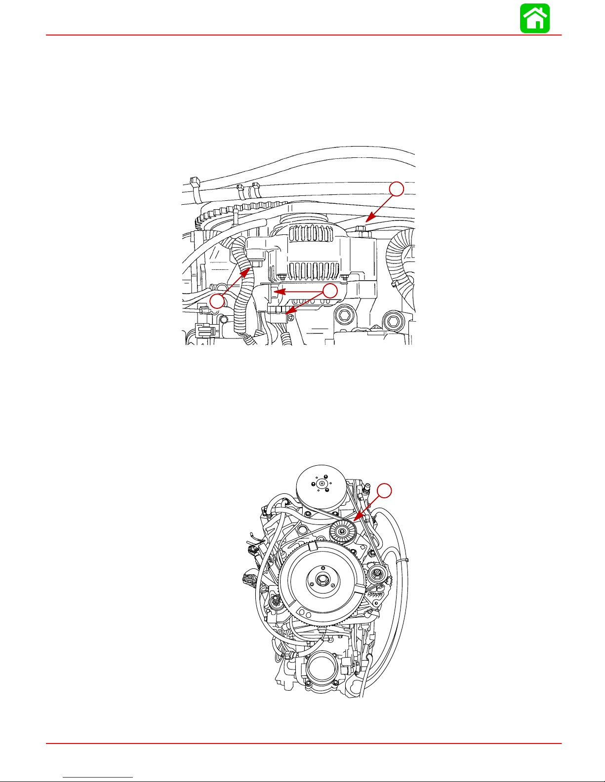
CHARGING & STARTING SYSTEM
Installation
1. Secure alternator to engine block with attaching bolts. Torque top bolt to 40 lb-ft (54
Nm). Torque bottom bolt to 35 lb-ft (47.5 Nm).
2. Install alternator belt in V-groove of flywheel and alternator pulley.
3. Reconnect electrical harness to alternator.
a
a
c
c
b
b
a-Top Bolt [Torque to 40 lb-ft (54 Nm)]
b-Bottom Bolt [Torque to 35 lb-ft. (47.5 Nm)]
c-Harnesses
Alternator Belt Tension Adjustment
Correct alternator belt tension is maintained by a belt tensioner assembly.
56117
a
a
a-Belt Tensioner Assembly
Page 2B-22 90-855347R1 JANUARY 1999
56142
Page 97
Starter System
Starter Motor Amperes Draw
STARTER MOTOR NO LOAD NORMAL
PART NO. AMP. DRAW AMP. DRAW
50-833153-1 30 AMPS 165 AMPS
Starter System Components
1. Battery
2. Starter Solenoid
3. Neutral Start Switch
4. Starter Motor
5. Ignition Switch
Description
The battery supplies electricity to activate the starter motor. When the ignition is turned
to the “ST ART” position, the starter solenoid is energized and completes the starter circuit
between the battery and starter.
CHARGING & STARTING SYSTEM
The neutral start switch opens the starter circuit when the shift control lever is not in neutral thus preventing accidental starting when the engine is in gear.
CAUTION
The starter motor may be damaged if operated continuously. DO NOT operate
continuously for more than 30 seconds. Allow a 2 minute cooling period between
starting attempts.
90-855347R1 JANUARY 1999 Page 2B-23
Page 98

CHARGING & STARTING SYSTEM
REF
Starter Motor
4
3
5
1
14
2
15
10
17
6
7
8
9
15
14
18
14
.
NO.
1 1 STARTER MOTOR
2 1 DRIVE CAP
3 2 THRU BOL T 70 8
4 1 DRIVE KIT
5 1 PINION
6 1 ARMATURE
7 1 BRUSH/SPRING KIT
8 1 BRUSH HOLDER
9 1 COMMUT ATOR CAP
10 2 SCREW Drive Tight
11 1 LOCKWASHER
12 1 NUT (1/4-20) 35 4.0
13 1 LOCKWASHER
14 1 NUT (1/4-20) 35 4.0
15 3 SCREW (5/16-18 x 1-3/4) 210 17.5 24
16 1 BATTERY CABLE (NEGATIVE)
17 1 DECAL-Warning-High Voltage
18 1 BOOT
2 Cycle Outboard Oil (92-826666A24)
QTY. DESCRIPTION lb-in lb-ft Nm.
13
16
12
11
7
TORQUE
Page 2B-24 90-855347R1 JANUARY 1999
Page 99
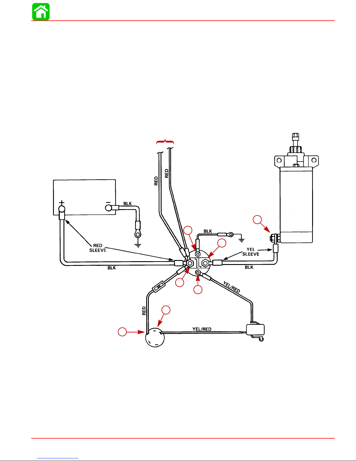
Troubleshooting the Starter Circuit
Before beginning the troubleshooting flow chart, verify the following conditions:
1. Confirm that battery is fully charged.
2. Check that control lever is in “NEUTRAL” position.
3. Check terminals for corrosion and loose connections.
4. Check cables and wiring for frayed and worn insulation.
5. Check 20 amp fuse.
Location of “Test Points” (called out in flow chart) are numbered below.
TO ALTERNA TOR
CHARGING & STARTING SYSTEM
STARTER
BATTERY
20 AMP FUSE
5
5
4
4
IGNITION SWITCH
2
2
6
6
STARTER
SOLENOID
7
7
1
1
3
3
NEUTRAL ST ART SWITCH
(LOCATED IN CONTROL HOUSING)
90-855347R1 JANUARY 1999 Page 2B-25
Starter Circuit
Page 100
CHARGING & STARTING SYSTEM
Starter Circuit Troubleshooting Flow Chart
Starter Motor Does Not Turn
SAFETY WARNING: Disconnect yellow (starter motor)
cable from starter solenoid test point 1 BEFORE making
tests 1–thru–7 to prevent unexpected engine cranking.
TEST 1
Use an ohmmeter (Rx1 scale) and connect meter leads
between NEGATIVE (–) battery post and common powerhead ground.
No Continuity Indicated – There is an open circuit in the
BLACK NEGATIVE (–) battery cable between the NEGATIVE (–)
battery post and the powerhead.
• Check cable for loose or corroded connections.
• Check cable for open.
Test 2
No voltage reading:
proceed to TEST 3.
a. Disconnect BLACK ground wire(s) from Test Point 2.
b. Connect voltmeter between common engine ground and Test Point 2.
c. Turn ignition key to “Start” position.
TEST 3
a. Reconnect BLACK ground wire.
b. Connect voltmeter between common engine ground and Test Point 3.
c. Turn ignition key to “Start” position.
No voltage reading:
proceed to Step 4
12 Volt Reading
Defective starter solenoid
TEST 4
a. Connect voltmeter between common
No voltage reading:
proceed to Test 5
engine ground and Test Point 4.
b. Turn ignition key to “Start” position.
Continuity Indicated
Proceed to TEST 2
12 Volt Reading*
Check BLACK ground wire for poor connection
or open circuit.
Reconnect ground wire to starter solenoid.
Proceed to TEST 7.
12 Volt Reading*
Neutral start switch is open or YELLOW/RED
wire is open between Test Points 4 and 3.
TEST 5
No voltage reading:
proceed to Test 6
Connect voltmeter between common
engine ground and Test Point 5
TEST 6
Check for voltage between common engine ground and Test Point 6.
No voltage reading:
Check RED wire between battery(+)
POSITIVE terminal and Test Point 6.
Page 2B-26 90-855347R1 JANUARY 1999
12 Volt Reading*
Defective ignition switch.
12 Volt Reading*
Check fuse in RED wire between Test
Points 5 and 6.
Check for open RED wire between Test
Points 5 and 6.
*Battery Voltage
 Loading...