

Page 1

Before driving
Introduction 2
Instrumentation 4
Controls and features 14
Seating and safety restraints 44
Starting and driving
Starting 76
Driving 84
Roadside emergencies 107
Contents
Servicing
Maintenance and care 125
Capacities and specifications 183
Reporting safety defects (U. S. only) 189
Index 190
1
Page 2

Introduction
ICONS
Indicates a warning. Read the
following section on Warnings for
a full explanation.
Indicates that vehicle information
related to recycling and other
environmental concerns will follow.
We must all play our part in
protecting the environment.
Correct vehicle usage and the
authorized disposal of waste
cleaning and lubrication materials
are significant steps toward this
aim.
WARNINGS
How can you reduce the risk of
personal injury and prevent
possible damage to others, your
vehicle and its equipment?
In this owner’s guide, answers to
such questions are contained in
comments highlighted by the
warning triangle symbol.
BREAKING IN YOUR VEHICLE
There are no particular breaking-in
rules for your vehicle. Simply avoid
driving too fast during the first
1 600 km (1 000 miles). Vary
speeds frequently. This is
necessary to give the moving parts
a chance to break in.
2
Page 3

If possible, you should avoid hard
braking for the first 1 600 km
(1 000 miles).
From 1 600 km (1 000 miles)
onwards you can gradually increase
the performance of your vehicle up
to the permitted maximum speeds.
INFORMATION ABOUT THIS
GUIDE
The information found in this guide
was in effect at the time of
printing. Ford may change the
contents without notice and
without incurring obligation.
Introduction
3
Page 4
Instrumentation
CHECK
ENGINE
O/D
OFF
Off
Res
Set
Acc
Coast
On
M
I
R
R
O
R
S
N
O
R
M
A
L
1
2
0
3
x 1000
4
5
6
7
8
000123
0 0 0 0
10
20
30
40
50
60
70
80
90
1 00
110
120
130
MPH
20
40
60
55
80
120
100
140
160
180
200
E F
1
/
2
UNLEADED FUEL ONLY
BRAKE
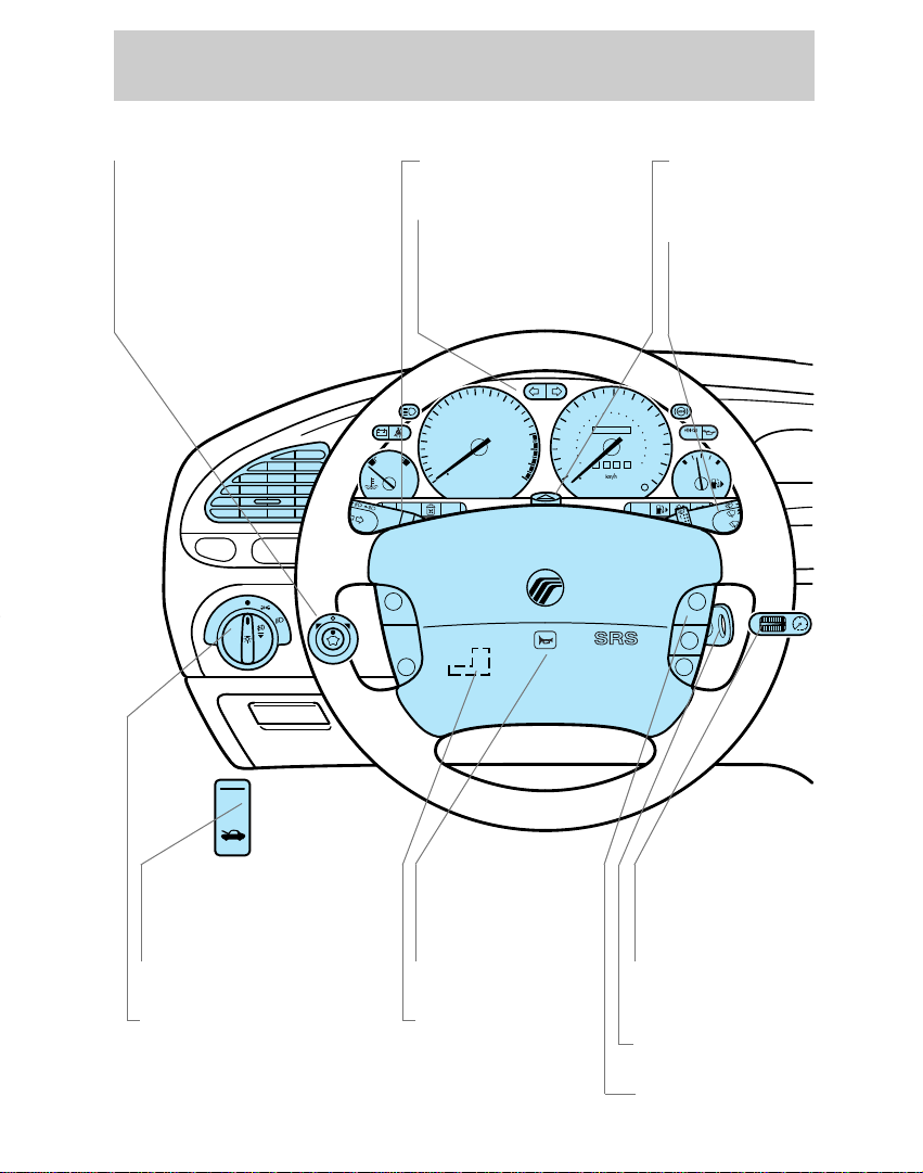
Page 17
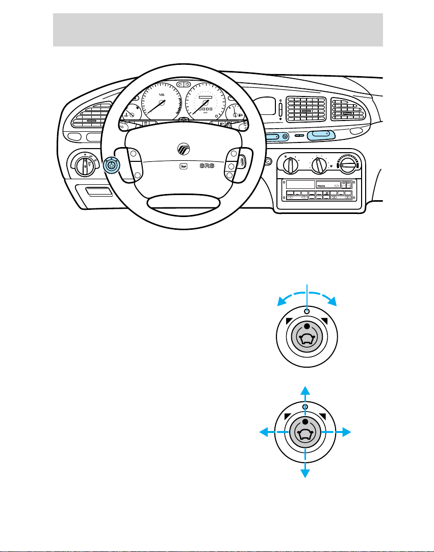
Power mirrors
Page 27
Turn signal/high beam
Page 6
Instrument cluster
Page 26
Hazard flasher
control
Page 28
Windshield
wiper/washer
control
Page 129
Hood release
Page 14
Headlamp control/
Foglamp control*
4
Page 26
Horn
Page 25
Tilt steering
wheel lever
Page 16
Instrument panel
dimmer switch
Page 24
Ignition switch
Page 29
Speed control*
Page 5
Instrumentation
POWER AUDIO AM/FM
SCAN
SEEK
31
2
64
5
ANS
SIDE 1-2
EJECT
VOLUME
DEF
LO
HI
OFF PNL/FLR
PANEL
A/C
FLOOR
FLR
DEF
MAX
A/C
:
I0 20
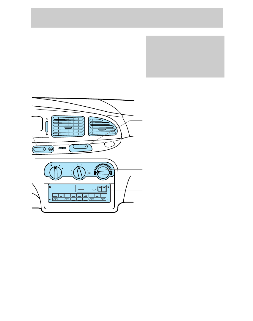
Page 16
Rear window
defroster control*
On various models the
appearance and location of
some items may differ from
those shown here. However,
the page references given
still apply.
Page 42
Anti-theft system status
indicator*
Page 18
Clock
Page 19
Climate control system
Electronic sound system;
refer to “Audio Guide”
* if equipped
5
Page 6
Instrumentation
000123
0 0 0 0
10
20
30
40
50
60
70
80
90
110
120
1 30
MPH
20
40
60
55
80
120
100
140
160
180
200
100
E F
1
/
2
UNLEADED FUEL ONLY
1
2
0
3
x 1000
4
5
6
7
8
N
O
R
M
A
L
BRAKE
CHECK
ENGINE
TRACTION
CONTROL
O/D
OFF
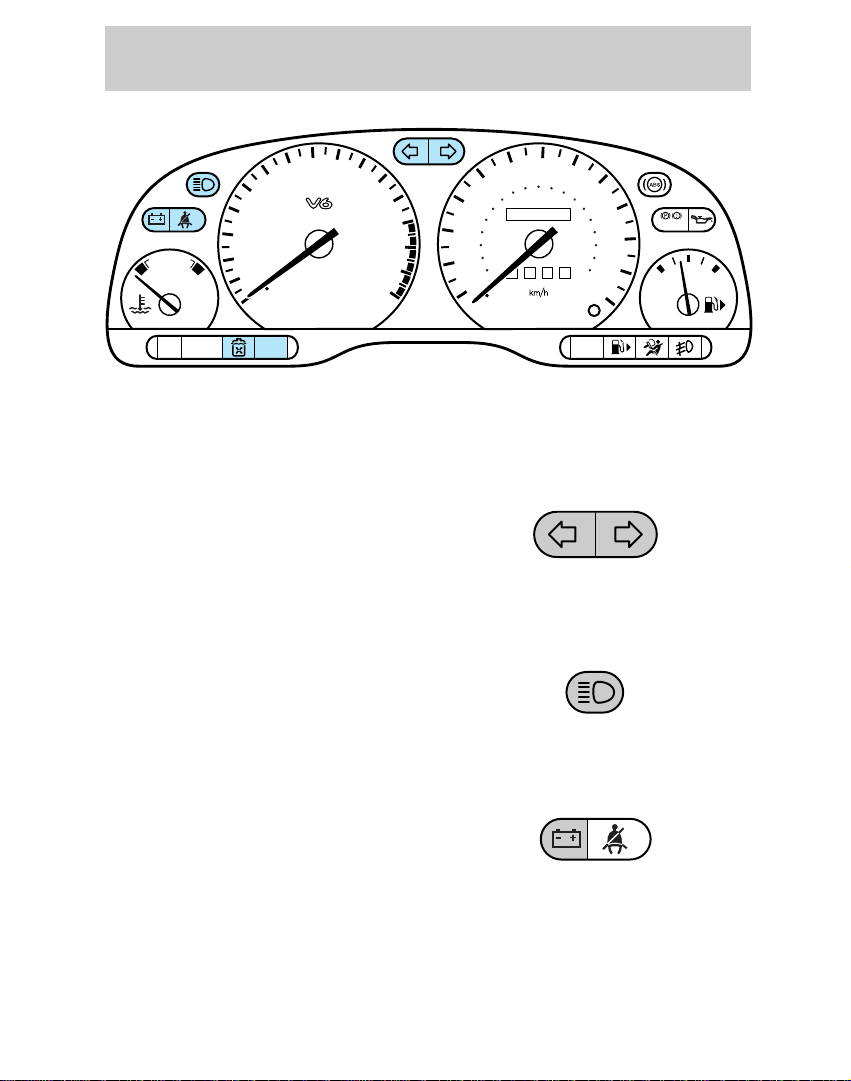
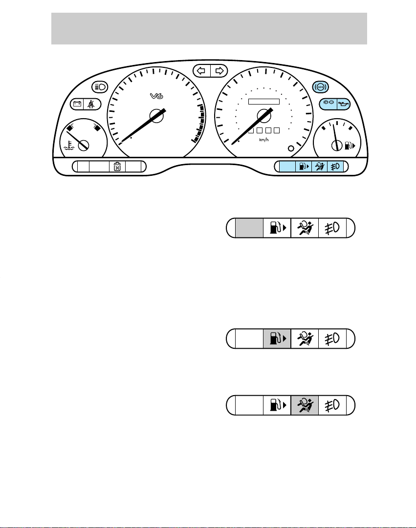
INSTRUMENT CLUSTER
LIGHTS AND CHIMES
Turn signal
Flashes when the left or right turn
signal or hazard lights are
activated.
High beams
Illuminates when the headlamp
high beams are on.
Charging system
Briefly illuminates when the
ignition is turned on and the engine
is off. The light also illuminates
when the battery is not charging
properly and the vehicle may
require electrical system service.
6
Page 7
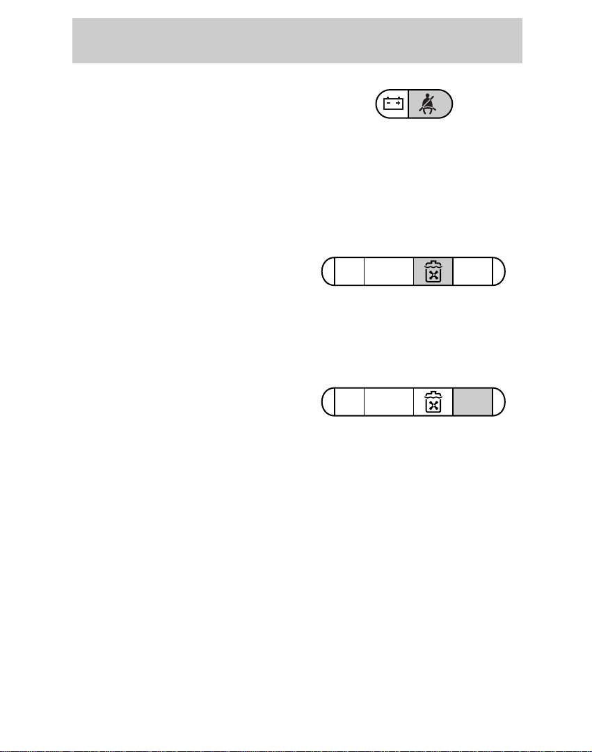
Safety belt
TRACTION
CONTROL
O/D
OFF
TRACTION
CONTROL
O/D
OFF
Illuminates when the ignition is
switched on as a reminder to fasten
the safety belts. For more
information, refer to Safety belt
indicator light and warning
chime in the Seating and safety
restraints chapter.
Low coolant (if equipped)
Briely illuminates when the ignition
is turned on and the engine is off.
Illuminates when the engine
coolant level is low. Refer to the
Maintenance and care chapter to
check the engine coolant level.
O/D Off indicator
(Automatic transaxle only)
Illuminates and remains
illuminated when the transaxle
control switch (TCS) on the end of
the gearshift lever is pressed and
overdrive is turned off.
Indicates the status of the
transaxle and will flash steadily if a
malfunction is detected. If the
flashing persists, have your
transaxle serviced by your dealer
or a qualified service technician as
soon as possible.
If the condition persists, your
transaxle may be damaged.
Instrumentation
7
Page 8
Instrumentation
CHECK
ENGINE
CHECK
ENGINE
000123
0 0 0 0
10
20
30
40
50
60
70
80
90
110
120
1 30
MPH
20
40
60
55
80
120
100
140
160
180
200
100
E F
1
/
2
UNLEADED FUEL ONLY
1
2
0
3
x 1000
4
5
6
7
8
N
O
R
M
A
L
BRAKE
CHECK
ENGINE
TRACTION
CONTROL
O/D
OFF
CHECK
ENGINE
Check engine
Illuminates when the ignition is
turned on and the engine is off.
Also illuminates when the engine’s
emission control system requires
service or if the fuel filler cap is
not fitted correctly.
Low fuel
Illuminates when the fuel level is
low.
Air bag readiness
Briefly illuminates when the
ignition is turned on. If the light
fails to illuminate, continues to
flash or remains on, have the
system serviced immediately.
8
Page 9
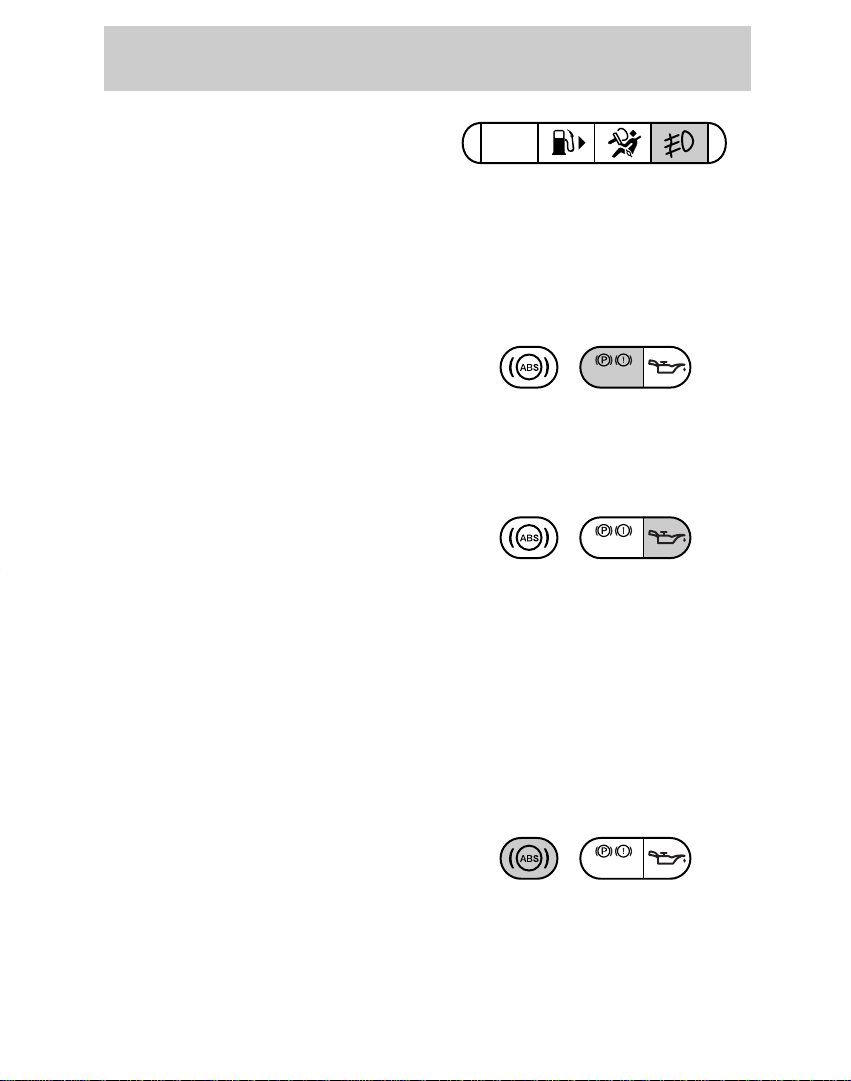
Front foglamps
CHECK
ENGINE
BRAKE
BRAKE
BRAKE
Illuminates when foglamps are
switched on.
Refer to Foglamps control in the
Controls and features chapter for
notes on use.
Brake system warning light
Extinguishes when the parking
brake is released. Illuminates after
releasing the parking brake to
indicate low brake fluid level.
Engine oil pressure
Briefly illuminates when the
ignition is turned on and the engine
is off. The light also illuminates
when engine oil pressure has been
lost. Refer to the Maintenance
and care chapter to check the
engine oil level as soon as possible.
If the engine oil level is correct and
the light stays on, see your dealer
or qualified service technician.
Instrumentation
Anti-lock brake system (ABS)
(if equipped)
Momentarily illuminates when the
ignition is turned on and the engine
is off. If the light stays on or
continues to flash, the ABS needs
to be serviced.
9
Page 10
Instrumentation
000123
0 0 0 0
10
20
30
40
50
60
70
80
90
110
120
1 30
MPH
20
40
60
55
80
120
100
140
160
180
200
100
E F
1
/
2
UNLEADED FUEL ONLY
1
2
0
3
x 1000
4
5
6
7
8
N
O
R
M
A
L
BRAKE
CHECK
ENGINE
TRACTION
CONTROL
O/D
OFF
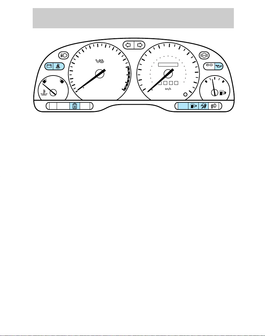
Testing the warning and
indicator lights and chimes
Turn the ignition key to the on
position without starting the
engine. The following warning and
indicator lights will illuminate
briefly: charging system, safety belt
(does not illuminate, if the driver’s
safety belt is fastened), low
coolant, low fuel, engine oil
pressure, check engine and air bag
readiness.
If any of these lights do not
illuminate, see your dealer or
qualified service technician.
10
Page 11

Headlamps on warning chime
Sounds when the headlamps are
on, the ignition is off (and the key
is not in the ignition) and the
driver’s door is open.
Key-in-ignition warning chime
Sounds when the key is left in the
off/lock or accessory position and
the driver’s door is open.
Safety belt warning chime
For information on the safety belt
warning chime, refer to the
Seating and safety restraints
chapter.
Instrumentation
Air bag supplemental restraint
system (SRS) warning chime
For information on the SRS
warning chime, refer to the
Seating and safety restraints
chapter.
11
Page 12
Instrumentation
N
O
R
M
A
L
000123
0 0 0 0
10
20
30
40
50
60
70
80
90
110
120
1 30
MPH
20
40
60
55
80
120
100
140
160
180
200
100
E F
1
/
2
UNLEADED FUEL ONLY
1
2
0
3
x 1000
4
5
6
7
8
N
O
R
M
A
L
BRAKE
CHECK
ENGINE
TRACTION
CONTROL
O/D
OFF
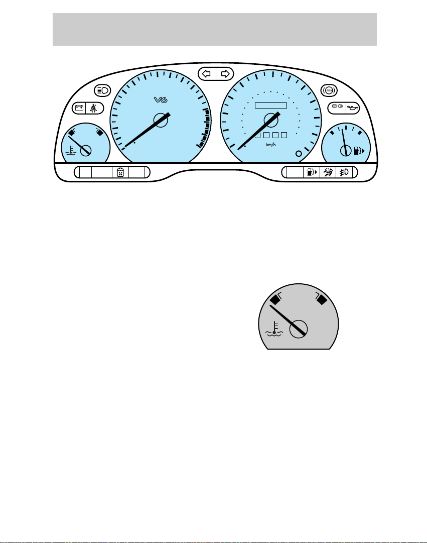
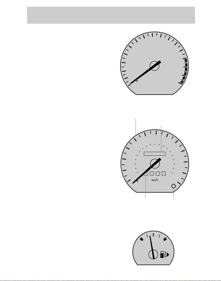
INSTRUMENT CLUSTER
GAUGES
Engine coolant temperature
gauge
Indicates the temperature of the
engine coolant. At normal
operating temperature, the needle
remains within the NORMAL area.
If it enters the red section, the
engine is overheating. Switch off
the ignition and determine the
source of the problem. Refer to
Checking and adding engine
coolant in the Maintenance and
care chapter.
12
Page 13
000123
0 0 0 0
10
20
30
40
50
60
70
80
90
110
120
1 30
MPH
20
40
60
55
80
120
100
140
160
180
200
100
E F
1
/
2
UNLEADED FUEL ONLY
Tachometer
1
2
0
3
x 1000
4
5
6
7
8
Indicates the engine speed in
revolutions per minute (rpm).
Instrumentation
Speedometer
Indicates the current vehicle
speed.
Odometer
Registers the total mileage of the
vehicle.
Trip odometer
The trip odometer can register the
mileage of individual journeys. To
reset, depress the button.
Fuel gauge
The fuel gauge displays the
approximate level of usable fuel left
in the fuel reservoir.
Speedometer
Odometer
Trip odometer Reset button
13
Page 14
Controls and features
POWER AUDIO AM/FM
SCAN
SEEK
31
2
64
5
ANS
SIDE 1-2
EJECT
VOLUME
M
I
R
R
O
R
S
DEF
LO
HI
OFF PNL/FLR
PANEL
A/C
FLOOR
FLR
DEF
MAX
A/C
T/C OFF
000123
0 00 0
10
20
30
40
50
60
70
80
90
100
110
120
130
MPH
20
40
60
55
80
120
100
140
160
180
200
E F
1
/
2
UNLEADED FUEL ONLY
1
2
0
3
x 1000
4
5
6
7
8
N
O
R
M
A
L
BRAKE
CHECK
ENGINE
TRACTION
CONTROL
O/D
OFF
:
I0 20
Off
Res
Set
Acc
Coast
On
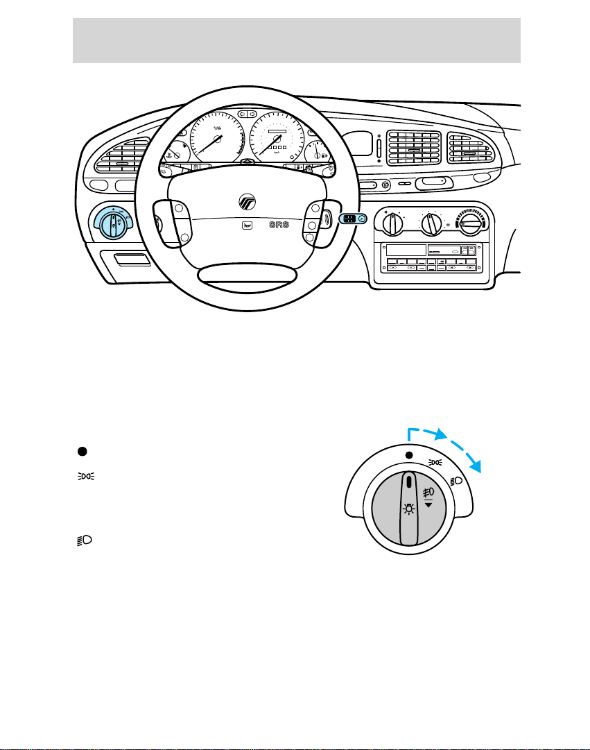
INSTRUMENT PANEL
CONTROLS
Headlamp control
Lamps off.
Turn one position clockwise:
Parking lamps, instrument panel
lamps, license plate lamps and tail
lamps on
Headlamps on.
Turn two positions clockwise:
14
Page 15
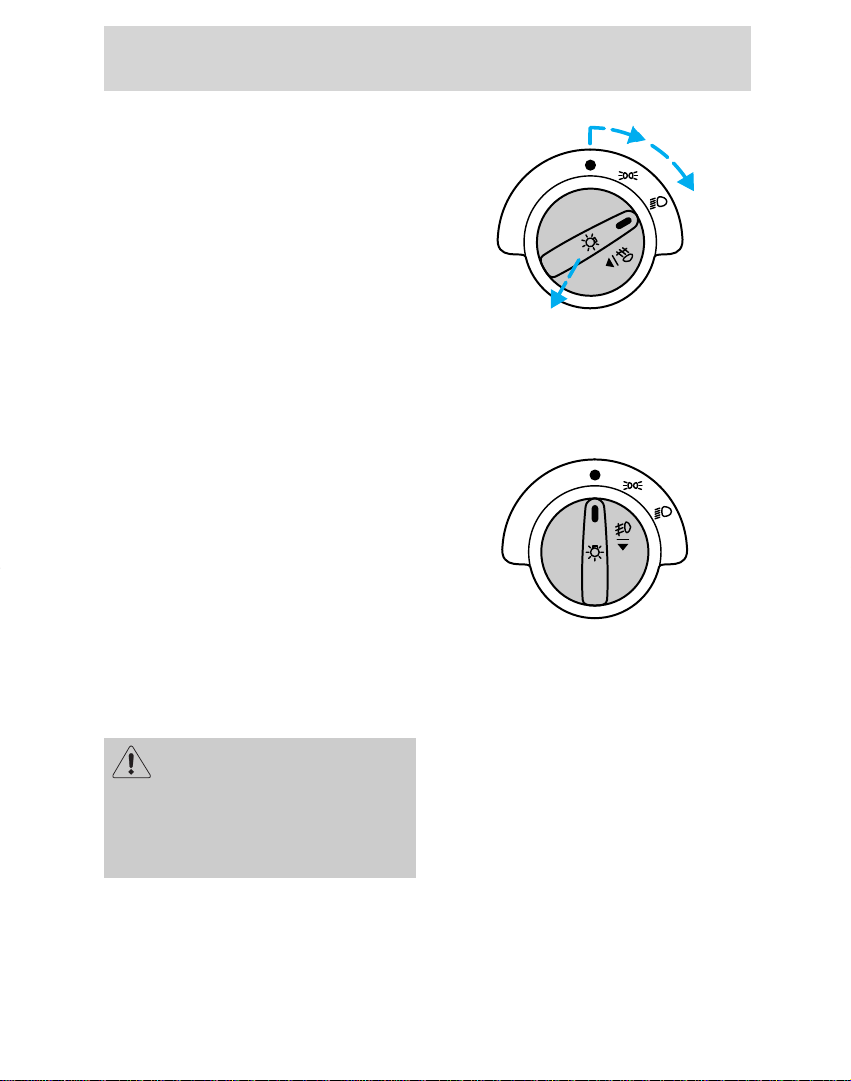
Foglamp control (if equipped)
Pull out the control while the
headlamps are on to turn the
foglamps on.
Push the control in to deactivate
the foglamps.
Daytime running light (DRL)
(Canadian vehicles only)
The DRL system turns on the
highbeam headlamps, with a
reduced light output, when:
• the vehicle is running and the
ignition is in the on position,
• the vehicle has a fully released
parking brake, and
• the headlamp system is in the off
position.
Controls and features
The daytime running light
(DRL) system will not
illuminate the tail lamps and
parking lamps. Turn on your
headlamps at dusk. Failure to do
so may result in a collision.
15
Page 16
Controls and features
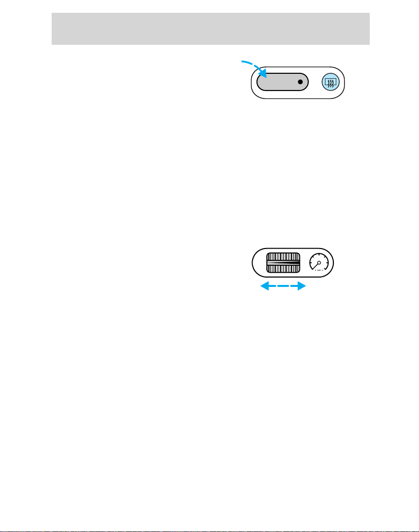
Rear window defroster
(if equipped)
Press the defroster control to clear
the rear window of thin ice and fog.
The ignition must be in the on
position to operate the rear
window defroster.
The defroster turns off
automatically after 10 minutes or
when the ignition is turned to the
off position. To manually turn off
the defroster, push the control
again.
Panel dimmer control
Adjust the control to vary the
intensity of the panel lighting.
Operates only when the exterior
lights are switched on.
16
Page 17
Power mirrors
M
I
R
R
O
R
S
M
I
R
R
O
R
S
POWER AUDIO AM/FM
SCAN
SEEK
31
2
64
5
ANS
SIDE 1-2
EJECT
VOLUME
DEF
LO
HI
OFF PNL/FLR
PANEL
A/C
FLOOR
FLR
DEF
MAX
A/C
000123
0 00 0
10
20
30
40
50
60
70
80
90
100
110
120
130
MPH
20
40
60
55
80
120
100
140
160
180
200
E F
1
/
2
UNLEADED FUEL ONLY
1
2
0
3
x 1000
4
5
6
7
8
N
O
R
M
A
L
BRAKE
CHECK
ENGINE
TRACTION
CONTROL
O/D
OFF
:
I0 20
Off
Res
Set
Acc
Coast
On
M
I
R
R
O
R
S
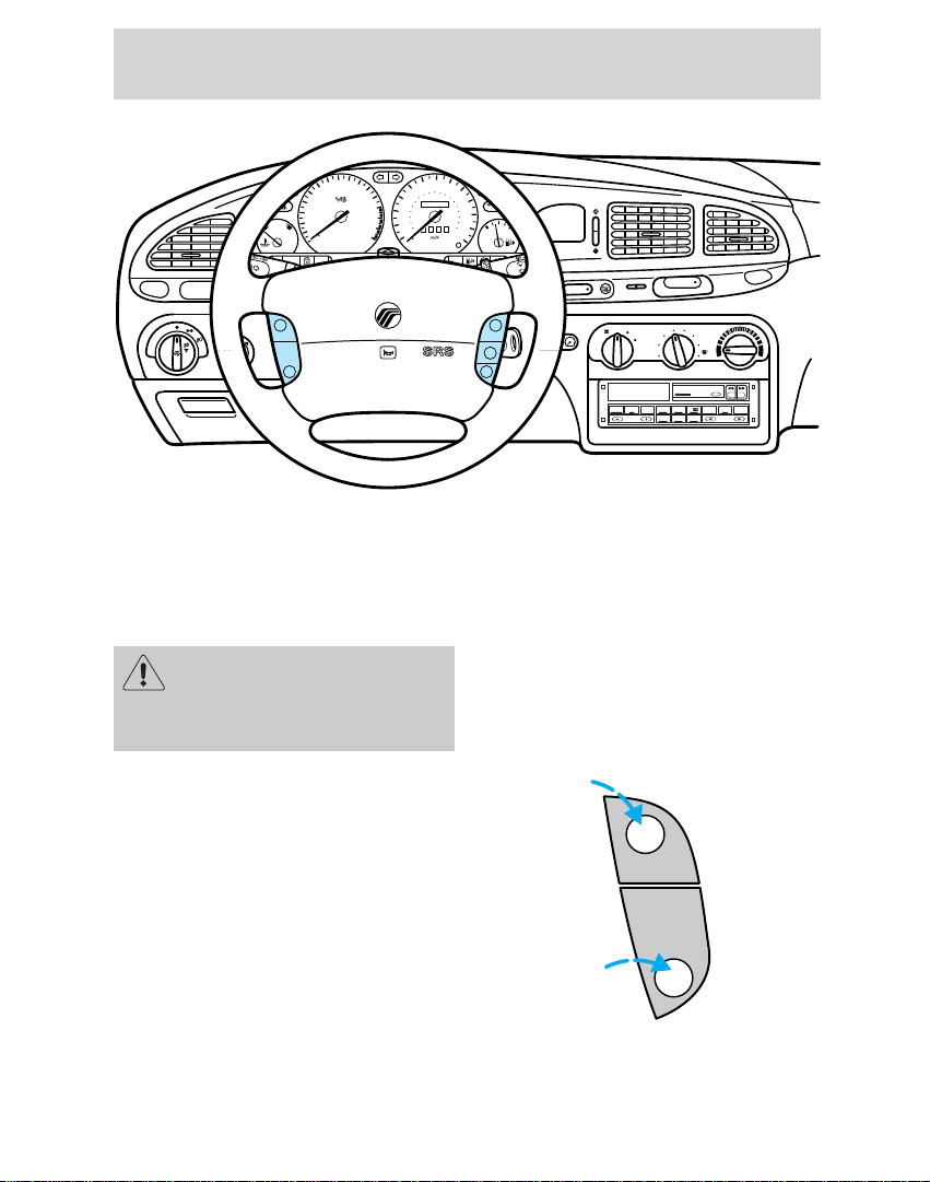
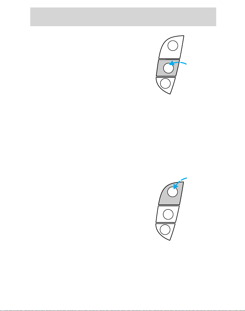
The control can be swivelled and
turned.
Turn the control counterclockwise
to adjust the driver’s side mirror,
clockwise to adjust the passenger’s
side mirror. Adjust the selected
mirror by moving the center
control in the desired direction.
Then turn the control back to the
center position.
Controls and features
17
Page 18
:
I0 20
Controls and features
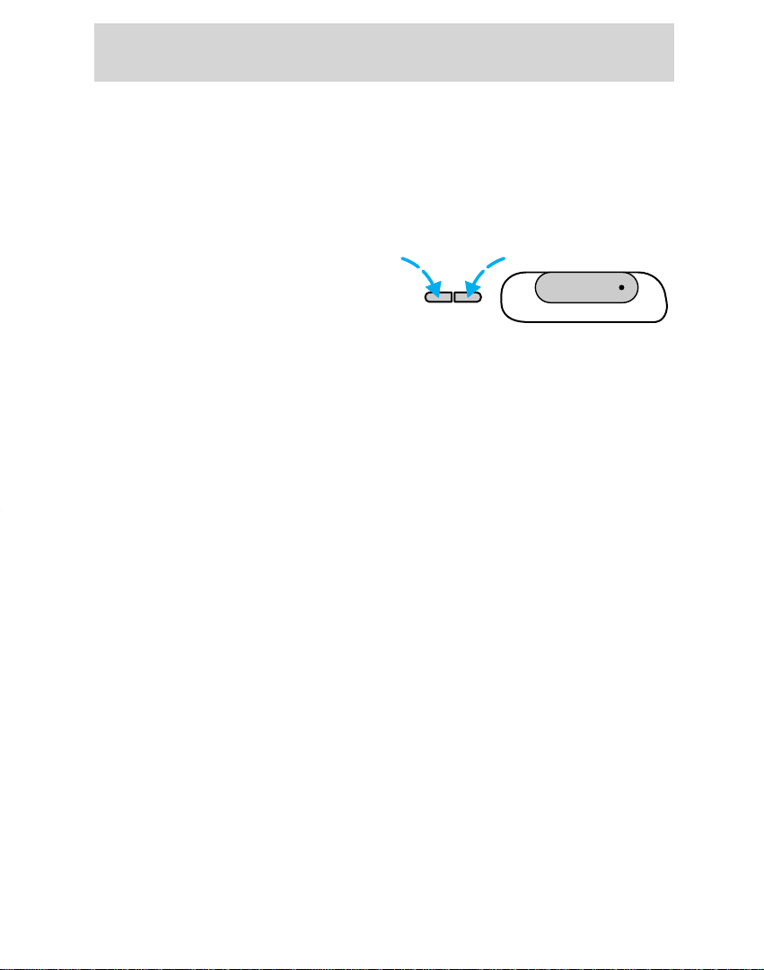
Digital clock
Switch the ignition on: The clock
can be set to either 12 or 24 hour
format.
To toggle between 12 or 24 hour
format, depress the H button and
the M button simultaneously and
then release them.
To advance the hours, press the H
button; to advance the minutes
press the M button. To advance
rapidly, depress and hold the
corresponding button.
Audio system
For information on the audio
system, refer to the “Audio Guide”.
Hours Minutes
18
Page 19
POWER AUDIO AM/FM
SCAN
SEEK
31
2
64
5
ANS
SIDE 1-2
EJECT
VOLUME
M
I
R
R
O
R
S
DEF
LO
HI
OFF PNL/FLR
PANEL
A/C
FLOOR
FLR
DEF
MAX
A/C
000123
0 0 0 0
10
20
30
40
50
60
70
80
90
100
110
120
130
MPH
20
40
60
55
80
120
100
140
160
180
200
E F
1
/
2
UNLEADED FUEL ONLY
1
2
0
3
x 1000
4
5
6
7
8
N
O
R
M
A
L
BRAKE
CHECK
ENGINE
TRACTION
CONTROL
O/D
OFF
:
I0 20
Off
Res
Set
Acc
Coast
On
Climate controls
Your vehicle has one of the
following climate control systems:
• Manual heating system
• Manual heating and air
conditioning system
In some modes, the two systems
function similarly. In modes where
the systems do not function
similarly, the different functions
are noted.
Controls and features
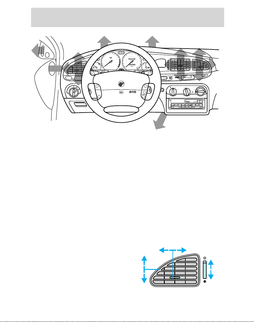
Vents
Airflow from the vents may be
adjusted by moving the horizontal
control or vertically adjusting the
vent according to your airflow
preference.
19
Page 20
Controls and features
OFF PNL/FLR
PANEL
A/C
*
FLOOR
DEF
*
FLR
DEF
*
MAX
*
A/C
LO
HI
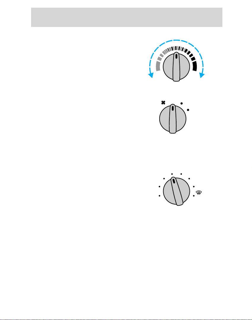
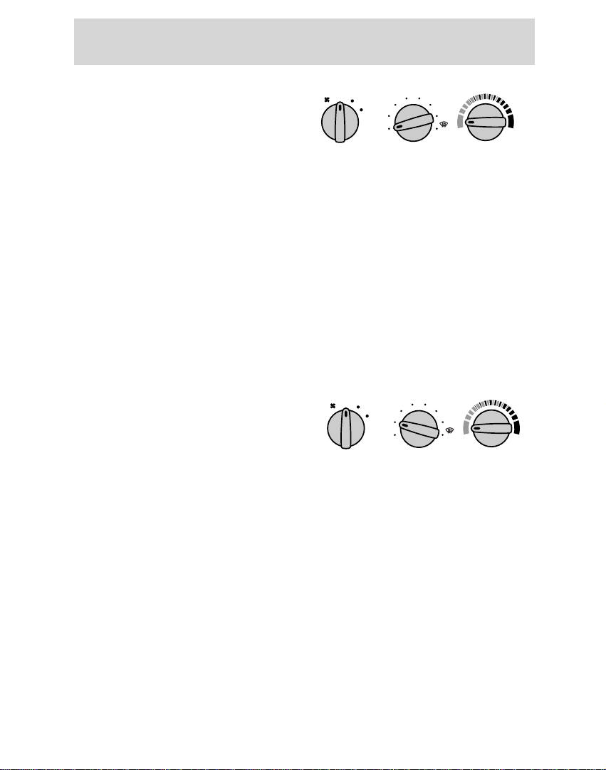
Temperature
Turn the temperature control to
the desired mix of warm or cool air
(left for cooler and right for
warmer).
Fan speed
Turn the fan speed control to the
desired speed.
Controlling airflow
Turn the mode control to the
desired airflow position.
The A/C compressor (if equipped)
operates in the positions marked *.
20
Page 21
Using MAX A/C mode
LO
HI
OFF PNL/FLR
PANEL
A/C
FLOOR
DEF
FLR
DEF
MAX
A/C
LO
HI
OFF PNL/FLR
PANEL
A/C
FLOOR
DEF
FLR
DEF
MAX
A/C
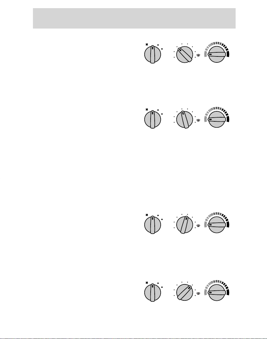
(if equipped)
The MAX A/C mode recirculates
the air and directs it to flow
through the instrument panel
vents.
This mode is noisier, but provides
quicker cooling than the A/C mode.
The A/C compressor only functions
if the outside temperature is above
10°C (50°F).
Using A/C mode (if equipped)
The A/C mode directs outside
conditioned air to flow through the
instrument panel vents. The A/C
mode can be used for heating,
ventilating and air conditioning.
The A/C compressor only functions
in the A/C mode if the outside
temperature is above 10°C (50°F).
Controls and features
21
Page 22
Controls and features
LO
HI
OFF PNL/FLR
PANEL
A/C
FLOOR
DEF
FLR
DEF
MAX
A/C
LO
HI
OFF PNL/FLR
PANEL
A/C
FLOOR
DEF
FLR
DEF
MAX
A/C
LO
HI
OFF PNL/FLR
PANEL
A/C
FLOOR
DEF
FLR
DEF
MAX
A/C
LO
HI
OFF PNL/FLR
PANEL
A/C
FLOOR
DEF
FLR
DEF
MAX
A/C
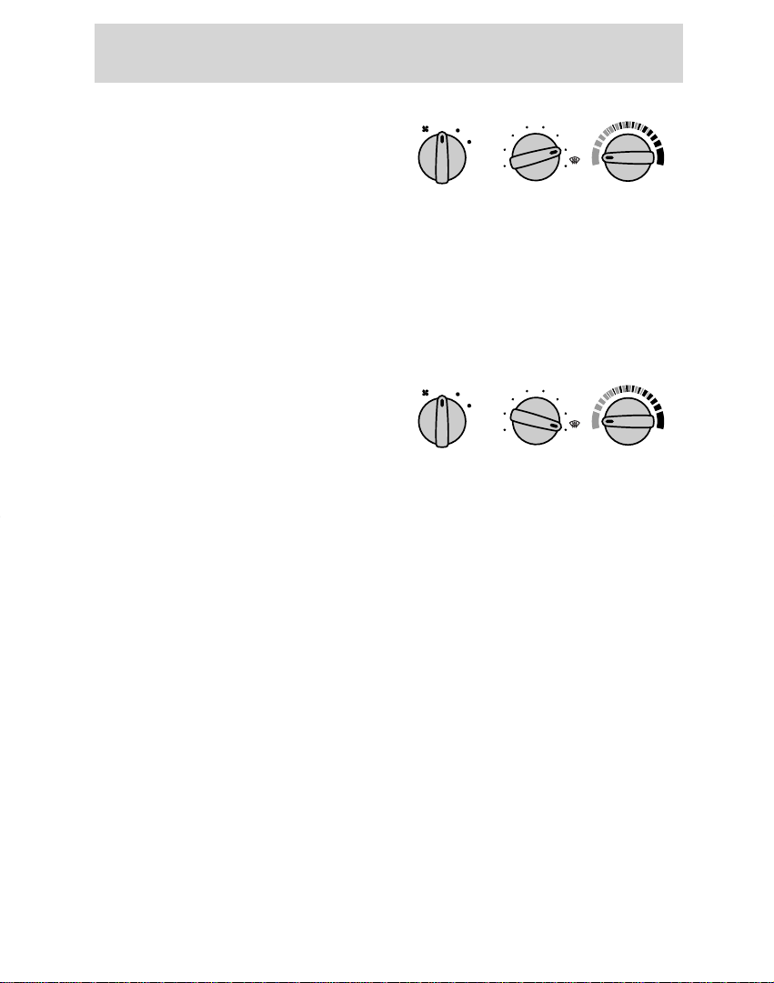
Using the PANEL mode
The panel mode directs outside air
to the panel vents.
OFF mode
Select the off position for all
climate control functions to cease.
The outside inlet door will close
and the fan will shut off.
Drive with the climate control
system on (either in heating or A/C
mode) to reduce humidity in your
vehicle.
Using the PNL/FLR mode
The panel/floor mode directs
outside air to flow through both the
panel and floor vents.
Using the FLOOR mode
The floor mode directs outside air
to the floor vents.
22
Page 23
Using the FLR/DEF mode
LO
HI
OFF PNL/FLR
PANEL
A/C
FLOOR
DEF
FLR
DEF
MAX
A/C
LO
HI
OFF PNL/FLR
PANEL
A/C
FLOOR
DEF
FLR
DEF
MAX
A/C
The floor/defrost mode directs
outside air to flow through the floor
vents and windshield defroster
vents. The A/C compressor (if
equipped) will function to
dehumidify the windows provided
the outside temperature is above
10°C (50°F).
Using the DEF mode
In addition to defogging and
demisting the front windshield, the
defrost mode of your vehicle also
has the capability to demist the
front side windows. The A/C
compressor (if equipped) will
function to dehumidify the
windows provided the outside
temperature is above 10°C (50°F).
Controls and features
Passenger compartment air
filter
Your vehicle is equipped with an air
filter that removes pollen and road
dust from outside air before it is
directed to the interior of the
vehicle. Refer to the Maintenance
and care chapter for maintenance
of this filter.
23
Page 24
Controls and features
3
4
2
1
I
R
R
O
R
S
000123
0 00 0
10
20
30
40
50
60
70
80
90
100
110
120
130
MPH
20
40
60
55
80
120
100
140
160
180
200
E F
1
/
2
UNLEADED FUEL ONLY
1
2
0
3
x 1000
4
5
6
7
8
N
O
R
M
A
L
BRAKE
CHECK
ENGINE
TRACTION
CONTROL
O/D
OFF
Off
Res
Set
Acc
Coast
On
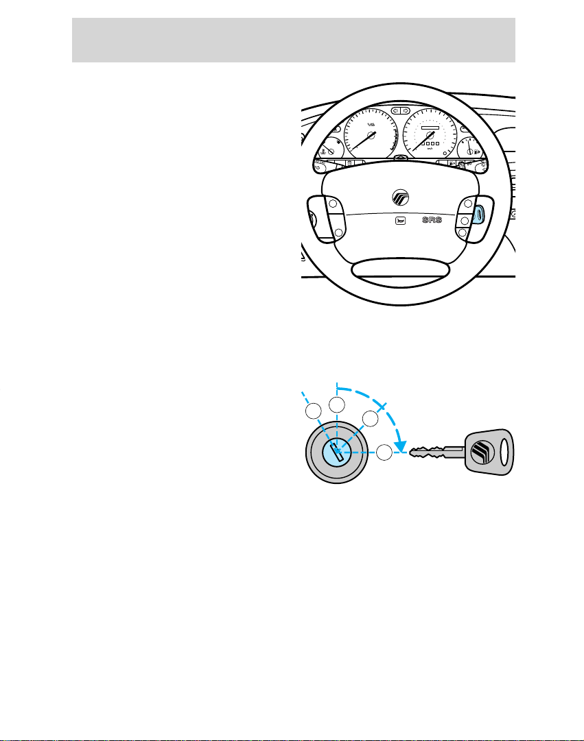
STEERING COLUMN
CONTROLS
Ignition
1. Ignition off, steering wheel
locked.
On vehicles with automatic
transaxles, the ignition key can
return to this position only if the
gearshift lever is in P (Park).
2. The accessory position. Steering
unlocked, radio operational.
Ignition and all main electrical
circuits are disabled.
The ignition key should not be left
in this position for too long to avoid
discharging the battery
unnecessarily.
3. Ignition switched on, all
electrical circuits operational.
Warning and indicator lights
illuminate. This key position is for
normal driving.
4. Starter motor activated. Release
the key as soon as the engine
starts.
24
Page 25
POWER AUDIO AM/FM
SCAN
SEEK
31
2
64
5
ANS
SIDE 1-2
EJECT
VOLUME
M
I
R
R
O
R
S
DEF
LO
HI
OFF PNL/FLR
PANEL
A/C
FLOOR
FLR
DEF
MAX
A/C
000123
0 00 0
10
20
30
40
50
60
70
80
90
100
110
120
130
MPH
20
40
60
55
80
120
100
140
160
180
200
E F
1
/
2
UNLEADED FUEL ONLY
1
2
0
3
x 1000
4
5
6
7
8
N
O
R
M
A
L
BRAKE
CHECK
ENGINE
TRACTION
CONTROL
O/D
OFF
:
I0 20
Off
Res
Set
Acc
Coast
On
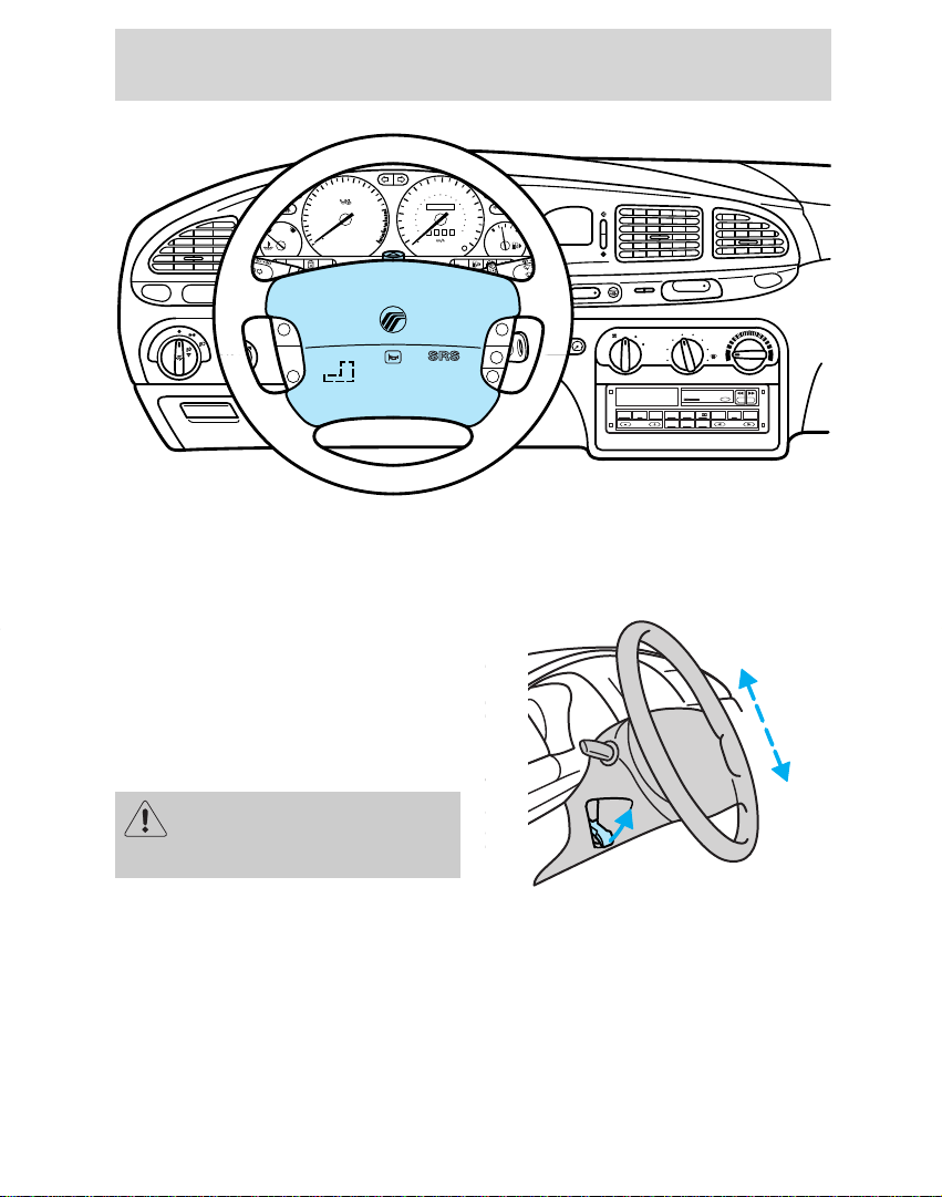
Tilt steering
Pull the locking lever on the
steering column cover up to adjust
the steering column position.
Secure the wheel by pushing the
locking lever down.
Controls and features
Never adjust the steering
wheel while the vehicle is
moving.
25
Page 26
Controls and features
Off
Res
Set
Acc
Coast
On
Off
Res
Set
Acc
Coast
On
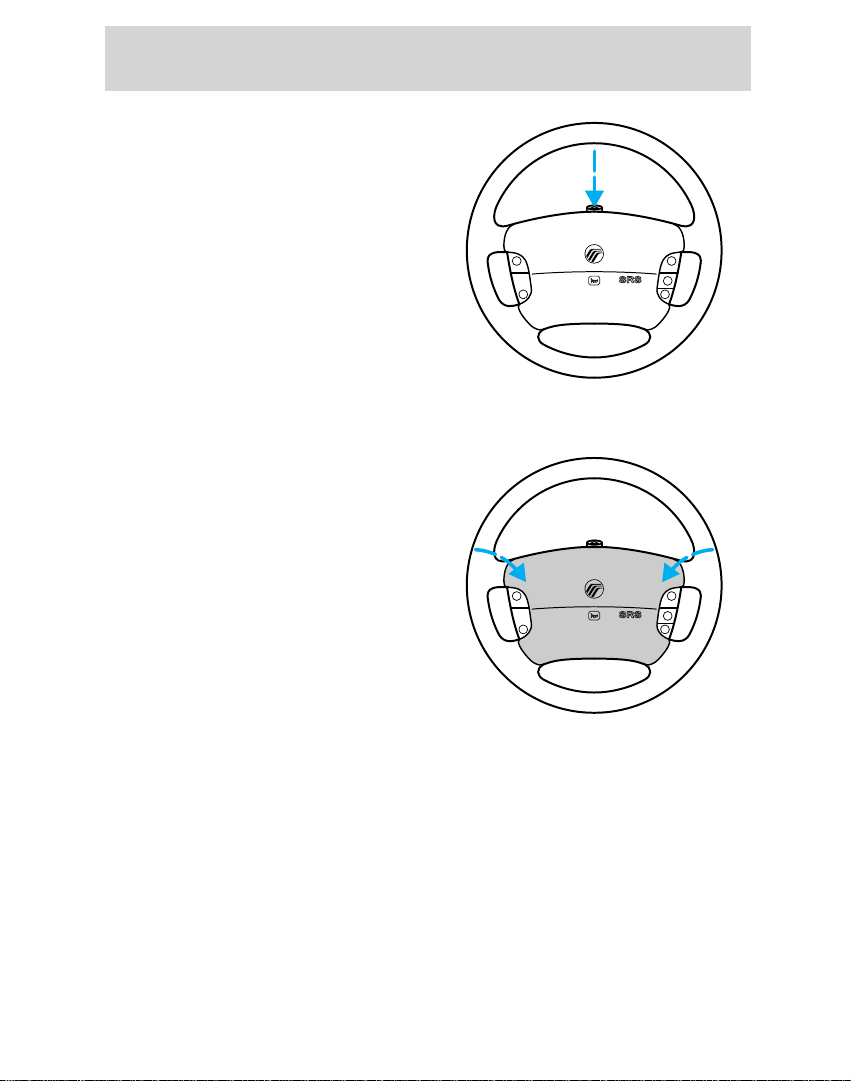
Hazard flasher control
Use only in an emergency to warn
traffic of vehicle breakdown or
approaching danger. Depress to
activate. Depress again to switch
off. The hazard lights can be
operated when the ignition is off.
Horn
Press the pad. The horn can be
operated when the ignition is off.
26
Page 27
POWER AUDIO AM/FM
SCAN
SEEK
31
2
64
5
ANS
SIDE 1-2
EJECT
VOLUME
M
I
R
R
O
R
S
DEF
LO
HI
OFF PNL/FLR
PANEL
A/C
FLOOR
FLR
DEF
MAX
A/C
000123
0 00 0
10
20
30
40
50
60
70
80
90
100
110
120
130
MPH
20
40
60
55
80
120
100
140
160
180
200
E F
1
/
2
UNLEADED FUEL ONLY
1
2
0
3
x 1000
4
5
6
7
8
N
O
R
M
A
L
BRAKE
CHECK
ENGINE
TRACTION
CONTROL
O/D
OFF
:
I0 20
Off
Res
Set
Acc
Coast
On
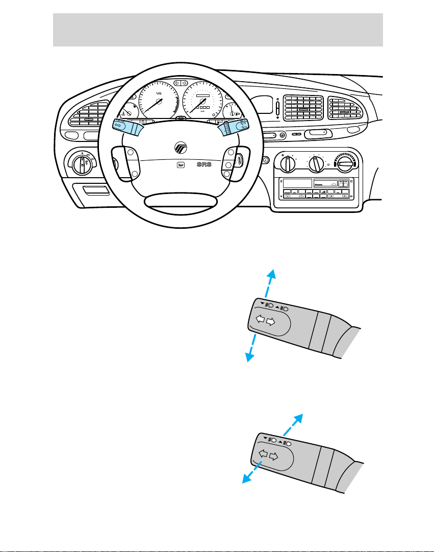
Multi-function switch
The turn signal functions are
available only with the ignition
switch on.
Right turn signal
Move the lever up.
Controls and features
Left turn signal
Move the lever down.
Flash-to-pass
Pull the lever toward you and
release quickly for “flash-to-pass”
operation.
High beam Headlamps
Push the lever toward the
instrument panel.
27
Page 28
Controls and features
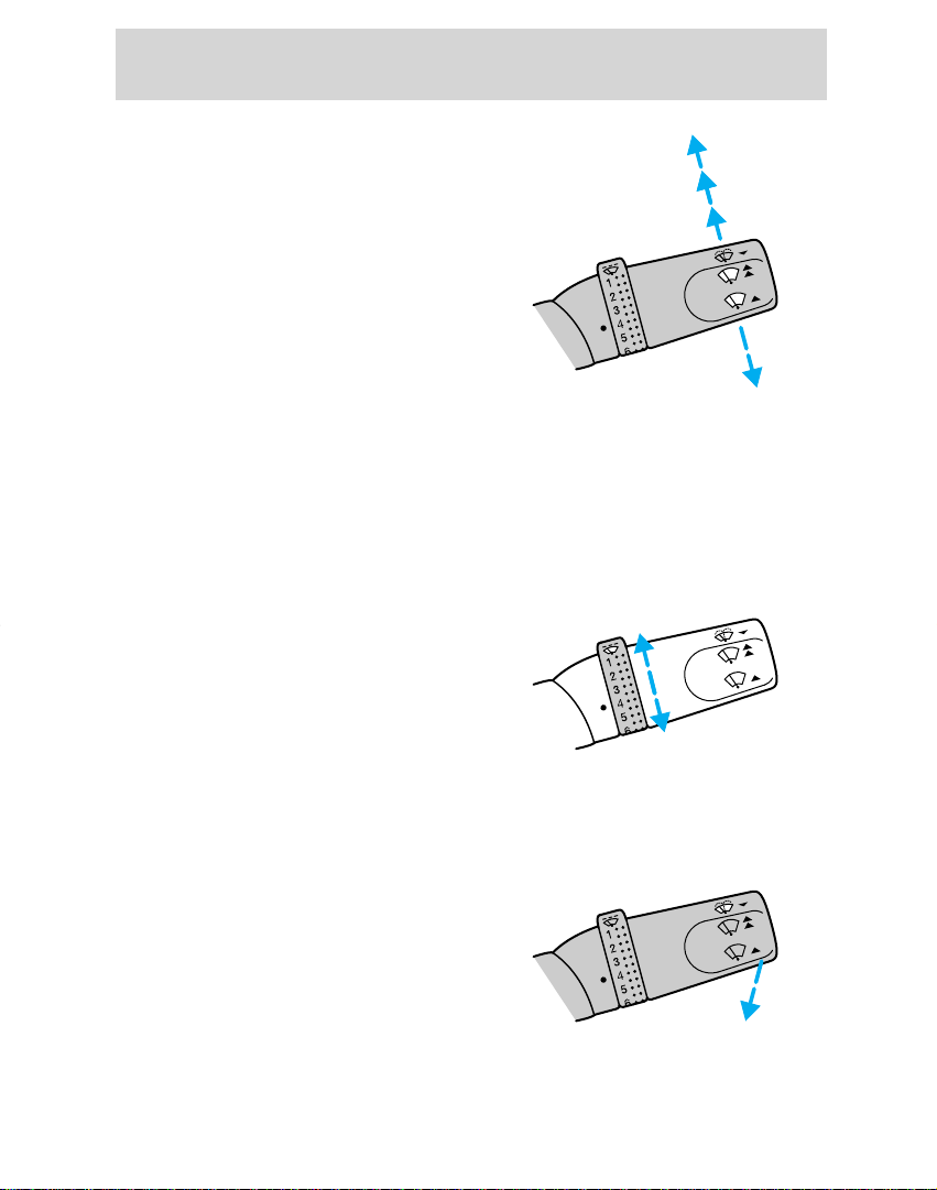
Windshield wipers and washer
Wipers
Lift the windshield wiper lever to
the desired speed interval.
• Intermittent: push lever up to the
first position.
• Low: push lever up to the second
position.
• High: push lever up to the third
position.
For a single wipe, push the lever
downward.
Intermittent wiper control
(if equipped)
Rotate the variable intermittent
wiper control to the desired speed.
1 = Short time interval
6 = Extended time interval
Washer
Pull the lever toward the steering
wheel. The washer operates in
conjunction with the windshield
wipers.
28
Page 29
Off
On
Speed control (if equipped)
POWER AUDIO AM/FM
SCAN
SEEK
31
2
64
5
ANS
SIDE 1-2
EJECT
VOLUME
M
I
R
R
O
R
S
DEF
LO
HI
OFF PNL/FLR
PANEL
A/C
FLOOR
FLR
DEF
MAX
A/C
000123
0 00 0
10
20
30
40
50
60
70
80
90
100
110
120
130
MPH
20
40
60
55
80
120
100
140
160
180
200
E F
1
/
2
UNLEADED FUEL ONLY
1
2
0
3
x 1000
4
5
6
7
8
N
O
R
M
A
L
BRAKE
CHECK
ENGINE
TRACTION
CONTROL
O/D
OFF
:
I0 20
Off
Res
Set
Acc
Coast
On
Do not use the speed control
in heavy traffic or on roads
that are winding, slippery, or
unpaved.
Controls and features
To turn speed control off
• Press Off or
• turn off the vehicle ignition.
Once speed control is switched off,
the previously programmed set
speed will be erased.
To turn speed control on
• Press On.
29
Page 30
Controls and features
Res
Set
Acc
Coast
Res
Set
Acc
Coast
To set a speed
Press Set Acc. For speed control to
operate, the speed control must be
on and the vehicle speed must be
greater than 48 km/h (30 mph).
If you drive up or down a steep hill,
your vehicle speed may vary
momentarily slower or faster than
the set speed. This is normal.
Speed control cannot reduce the
vehicle speed if it increases above
the set speed on a downhill. If your
vehicle speed is faster than the set
speed while driving on a downhill
in overdrive, you may want to shift
to the next lower gear to reduce
your vehicle speed.
If your vehicle slows down more
than 16 km/h (10 mph) below your
set speed on an uphill, your speed
control will disengage. This is
normal. Press Res to re-engage it.
30
Page 31

Res
Set
Acc
Coast
To set a higher speed
Res
Set
Acc
Coast
• Press and hold Set Acc. Release
when the desired set speed is
reached, or
• press and release Set Acc. Each
press will increase the set speed
by 1.6 km/h (1 mph) or
• accelerate with your accelerator
pedal, then press Set Acc.
You may accelerate with the
accelerator pedal at any time
during speed control usage.
Releasing the accelerator pedal will
return your vehicle speed to the
previously set speed.
To set a lower speed
• Press and hold Coast. Release the
control when the desired vehicle
speed is reached, or
• press and release Coast. Each
press will decrease the set speed
by 1.6 km/h (1 mph), or
• depress the brake pedal. When
the desired vehicle speed is
reached, press Set Acc.
Controls and features
31
Page 32

Controls and features
Res
Set
Acc
Coast
To return to a set speed
• Press Res. For Res to operate,
the vehicle speed must be faster
than 48 km/h (30 mph).
To disengage speed control
• Depress the brake pedal.
Disengaging the speed control will
not erase the previously
programmed set speed.
32
Page 33

12
SEC
OVERHEAD CONTROLS
Controls and features
Interior lamps
The interior lamps have three
switch positions: door delay, off
and on.
When the control is switched to
door delay (12 SEC), the interior
light stays on for 12 seconds after
the doors are closed with the
ignition off.
Reading lamps (if equipped)
The reading lamps are operated by
separate on/off switches and can be
adjusted to point in the desired
direction.
Sunroof (if equipped)
The electric sunroof can be
operated only when the ignition is
switched on.
To open and close the sunroof
Press the rear part of the control
on the rocker switch in the roof
console to open the sunroof. Press
the front control to close it.
Door delay
Off
On
On Off 12 SEC
Open/Lift
Close
To lift the rear of the sunroof
Close the sunroof and press the
front part of the control again.
Press the rear control to lower the
sunroof.
33
Page 34

Controls and features
AUTO
AUTO
U
L
DOOR LOCK
LOCK
DOOR MOUNTED CONTROLS
Power door locks (if equipped)
Push to lock or unlock all doors.
Power windows (if equipped)
The windows will only operate
when the ignition is switched on.
Press the appropriate control to
operate the power windows at each
door position. All of the windows
can be controlled from the control
on the driver’s door. The
passenger’s door window and the
rear windows can be operated
individually with separate door
controls on the respective door.
One-touch down feature
(driver only)
Briefly press the control to the
second action point: the window
opens automatically.
Press again to stop the window
while it is in motion.
34
Page 35

Safety switch
CHILD LOCK BELOW
SECURITE ENFANTS CI-DESSOUS
´
VERROUILLEE
,
LOCKED
WHEN LOCKED,
DOOR WON`T
OPEN FROM INSIDE.
´
VERROULEE AINSI, LA PORTE
NE PEUT S´OUVRIR DE
L´INTERIEUR
.
CHILD LOCK BELOW
SECURITE ENFANTS CI-DESSOUS
´
VERROUILLEE
,
LOCKED
WHEN LOCKED,
DOOR WON`T
OPEN FROM INSIDE.
´
VERROULEE AINSI, LA PORTE
NE PEUT S´OUVRIR DE
L´INTERIEUR
.
Move the switch to the right to
prevent passengers from operating
the windows.
Move the switch to the left to allow
passengers to operate the windows.
Rear door childproof safety
locks
When the lever in the rear door
lock is pushed inwards, the door
can be opened only from the
outside of the vehicle.
Controls and features
35
Page 36

Controls and features
PULL
FLOOR MOUNTED CONTROLS
Parking brake
For information on the parking
brake, refer to Preparing to start
the vehicle in the Starting
chapter.
Remote luggage compartment
control
Pull the control located on the left
of the driver’s seat to open the
luggage compartment.
To disable the remote luggage
compartment release, depress the
control on the luggage
compartment latch that is marked
in orange before closing the
luggage compartment.
36
Page 37

Fuel pump shut-off switch
For information on the fuel pump
shut-off switch, refer to Fuel
pump shut-off switch in the
Roadside emergencies chapter.
Positive retention floor mat
(if equipped)
(Standard in Canada)
Position the floor mat in the
footwell. Place the mat eyelet over
the pointed end of the retention
post from the rear and rotate
forward to install. Adjust the floor
mat position to allow proper
operation of accelerator pedal,
brake pedal and clutch pedal (if
equipped).
To remove, lift the floor mat just
forward of the retention post and
rotate it rearward to disengage it
from the retention post.
Controls and features
37
Page 38

Controls and features
TRUNK
UN
LOCK
PANIC
LOCK
TRUNK
LOCK
PANIC
UN
LOCK
REMOTE KEYLESS ENTRY
SYSTEM
(if equipped)
If your vehicle has a remote entry
system, you can lock and unlock
the vehicle doors and open the
luggage compartment without
using a key. The remote also has a
personal alarm feature.
The remote entry feature only
operates with the ignition in the off
position.
Locking the doors
Press the LOCK control.
To signal that the doors are locked,
press the LOCK control again
within five seconds. The doors will
lock again and the horn will sound.
Unlocking the doors
Press the UNLOCK control to open
the driver’s door.
To unlock the other doors, press
the UNLOCK control a second time
within five seconds.
38
Page 39

Opening the luggage
UN
LOCK
LOCK
PANIC
TRUNK
TRUNK
UN
LOCK
LOCK
PANIC
compartment
Press the TRUNK control.
Sounding the panic alarm
Press the PANIC control. The horn
will sound and the headlamps and
tail lamps will flash for
approximately two minutes and
forty-five seconds.
To deactivate the alarm, press the
PANIC control again or turn the
ignition key to the on position.
Replacing the batteries
The transmitter is powered by two
coin-type, three-volt lithium
batteries. A decrease in operating
range can be caused by:
• battery failure,
• weather conditions, or
• structures around the vehicle.
Replacement batteries for the
remote entry system transmitters
may be purchased at pharmacies,
watch stores or at authorized
dealers.
Controls and features
39
Page 40

Controls and features
To replace the batteries:
1. Twist a thin coin between the
two halves of the transmitter. Do
not take the front part of the
transmitter apart.
2. Remove the old batteries.
3. Place the positive (+) side of the
new batteries down.
4. Snap the two halves of the
transmitter back together.
Replacing lost transmitters
Take your transmitters to the
dealer for reprogramming if:
• a transmitter is lost or
• you want to purchase additional
transmitters.
This device complies with part 15
of the FCC rules. Operation is
subject to the two following
conditions: (1) The device may not
cause harmful interference, and
(2) This device must accept any
interference received, including
interference that may cause
undesired operation.
40
Page 41

PASSIVE ANTI-THEFT SYSTEM
POWER AUDIO AM/FM
SCAN
SEEK
31
2
64
5
ANS
SIDE 1-2
EJECT
VOLUME
DEF
LO
HI
OFF PNL/FLR
PANEL
A/C
FLOOR
FLR
DEF
MAX
A/C
E F
1
/
2
UNLEADED FUEL ONLY
BRAKE
:
I0 20
Res
Set
Acc
Coast
(if equipped)
The Passive Anti-Theft system
(PATS) is an engine immobilization
system. It is an additional theft
protection feature which prevents
the engine from being started
unless a coded key is used..
This system is only available with
2.5 l engines.
Automatic arming
The system is armed five seconds
after switching off the ignition.
The armed status is indicated when
the control light flashes every
two seconds.
Automatic disarming
Switching on the ignition disarms
the system if the correct code is
recognized.
Controls and features
Your vehicle is supplied with two
coded keys.
Keys
Only these keys can be used to
start your vehicle.
41
Page 42

Controls and features
:
I0 20
Functional check
When the ignition is switched on,
the control light in the digital clock
will illuminate for approximately
three seconds to indicate that the
system is operating correctly.
If the control light flashes rapidly
for approximately one minute and
then repeatedly at irregular
intervals, the system did not
recognize the key code. Remove
the key and try again.
If the control light illuminates
continuously for approximately
one minute and then flashes
repeatedly at irregular intervals, a
system malfunction has occurred.
Have the malfunction repaired by
your dealer or a qualified
technician as soon as possible.
To ensure a trouble-free exchange
between vehicle and key, do not
shield the keys with any metal
objects.
42
Page 43

Key coding
3
4
2
1
Replacement keys or a maximum of
15 duplicate keys can be coded.
To program a key, cycle ignition
switch from (3) to (1) with a
programmed key. Within five
seconds of this cycle, insert a new
PATS key into ignition and turn to
(3) or (4). If successful, the theft
warning indicator will glow for two
seconds, and the vehicle can be
started. Repeat until all chosen
keys have been programmed.
The control light illuminates to
indicate a successful programming
operation.
Repeat the procedure to program
additional keys.
Your dealer can also delete keys
already programmed.
The system is maintenance free.
If keys become lost, you must have
your dealer clear and reprogram
the code for security reasons.
Controls and features
43
Page 44

Seating and safety restraints
HEAD RESTRAINTS
Adjusting the head restraints
Push or pull the head restraint to
the desired height.
Swivel the head restraint forward
or backward to the desired angle.
SEATING
Manually adjusting the seats
Pull the lever located inside the
front edge of the seat to move the
seat forward or backward.
Pull the lever on the outside of the
seat to recline the seat.
Never adjust the driver’s
seat or seatback when the
vehicle is moving.
44
Page 45

Seating and safety restraints
1
2
3
4 6
5
Adjusting the power seats
(if equipped)
Move the relevant control in the
respective direction to adjust the
seat, seatback and lumbar as
follows:
Seat
(1) Forward and backward
(2) Height of the entire seat
(3) Height of the front of the seat
(4) Height of the rear of the seat
Seatback
(5) Seatback inclination
Lumbar support
(6) Lumbar support
45
Page 46

Seating and safety restraints
Folding rear seats (if equipped)
Pull the release knob located in the
luggage compartment. Fold down
the seat. The seatback cannot be
released while the built-in childseat
(if equipped) is open.
If you are carrying objects that
might damage the center rear
three-point safety belt, you can
unbuckle the end of the belt from
the small buckle on the seat
cushion and let the retractor reel it
up. Reconnect the belt tongue to
the buckle when you fold the seat
back up.
To raise the rear seatback, push the
seatback upward until it locks in
place. Make sure it is firmly latched
by pushing forward and back on it.
Check to see that the seat
and seatback are latched
securely in position. Keep luggage
area free of objects that would
prevent proper engagement.
46
Page 47

Seating and safety restraints
SAFETY RESTRAINTS
Important safety restraints
precautions
The use of safety belts helps to
restrain both driver and passenger
in case of a collision. In most states
and Canada, the law requires the
use of safety belts.
Front and rear seat
occupants including
pregnant women, should wear
safety belts for optimum
protection in an accident.
Always drive and ride with
your seatback upright and
the lap belt snug and low across
the hips.
Lock the doors of your
vehicle before driving to
lessen the risk of the door coming
open in a collision.
Cargo should always be
secured to prevent it from
shifting and causing damage to the
vehicle or harm to passengers.
To prevent the risk of injury,
make sure children sit where
they can be properly restrained.
47
Page 48

Seating and safety restraints
Using safety restraints properly
Combination lap and shoulder
belt
Insert the tongue into the slot in
the buckle to fasten.
Push the red release button and
remove the tongue from the slot to
unfasten.
The passenger safety restraints in
the vehicle are combination lap and
shoulder belts. The front and rear
seat passenger safety belts have
two types of locking modes.
Each seating position in your
vehicle has a specific safety
belt assembly which is made up of
one buckle and one tongue that
are designed to be used as a pair.
Use the shoulder belt on the
outside shoulder only. Never wear
the shoulder belt under the arm.
Never swing it around your neck
over the inside shoulder.
Never use a single belt for more
than one person.
48
Page 49

Seating and safety restraints
Vehicle sensitive (emergency)
locking mode
The vehicle sensitive mode is the
normal retractor mode which locks
the belts in response to vehicle
movement. For example, if the
driver brakes suddenly, turns a
corner sharply or your vehicle
receives an impact of 8 km/h
(5 mph) or more the combination
safety belts will lock to help reduce
the forward movement of the
driver and passengers.
The retractor can be made to lock
by pulling sharply on the belt.
Automatic locking mode
In this mode, the shoulder belt is
automatically prelocked; however,
the belt will react to remove any
slack in the shoulder belt.
The automatic locking mode is not
available on the driver’s safety belt.
When to use the automatic
locking mode
• When a tight lap and shoulder
belt fit is desired.
• Any time a child safety seat is
installed in the vehicle. For
information on the proper use of
a child safety seat, refer to Child
safety seats later in this chapter.
49
Page 50

Seating and safety restraints
Using automatic locking mode
The automatic locking mode must
be used when installing a child
safety seat in any passenger seat.
1. Buckle the combination lap and
shoulder belt.
2. Grasp the shoulder belt portion
and pull downward until the entire
belt is extracted.
3. Allow the belt to retract. As the
belt retracts, you will hear a
clicking sound. This indicates that
the safety belt is now in the
automatic locking mode.
Canceling automatic locking
mode
Disconnect the combination lap
and shoulder belt and allow it to
completely retract. This will cancel
the automatic locking mode and
activate the vehicle sensitive
(emergency) locking mode.
50
Page 51

Seating and safety restraints
Front seat safety belt height
adjustment
Position the shoulder belt
height adjuster so that the
belt rests across the middle of
your shoulder. Be sure the
shoulder belt is properly
positioned on your shoulder each
time you use the belt. If the
shoulder belt is off your shoulder,
on your upper arm or neck, there
is a greater risk of severe injury in
a collision.
To lower the height of the shoulder
belt:
1. Push the control down.
2. Slide down.
To raise the height of the shoulder
belt:
1. Slide up.
2. Pull down on the height adjuster
to make sure that it is locked in
place.
51
Page 52

Seating and safety restraints
Center position three-point
safety belts
If the lower end of the belt has
been unbuckled, pull the belt
steadily from the reel and insert
the small tongue into the small
buckle until a distinct “click” is
heard.
This buckle should be left buckled
except when the seatback is folded
down and cargo that might damage
the seatbelt or get it dirty is being
hauled.
Pull the seat belt across the hips
and insert the big (sliding) tongue
into the appropriate buckle until a
distinct “click” is heard.
Should the center rear belt need to
be unlatched from its anchorage, a
thin probe is required to be
inserted into the hole located on
the underside of the floor mounted
buckle. If the buckle and tongue
are not reconnected, then the belt
is not save to be used.
Safety belt indicator light and
warning chime
Illuminates in the instrument
cluster and a chime sounds to
remind the occupants to fasten
their safety belts.
52
Page 53

Seating and safety restraints
Conditions of operation
If the driver’s safety belt is not
buckled before the ignition key is
turned to on, the safety belt
indicator illuminates for
1-2 minutes and the warning chime
sounds for 4-8 seconds.
If the driver’s safety belt is buckled
while the indicator light is
illuminated and the reminder
chime is sounding, the safety belt
indicator light and reminder turn
off.
Safety belt extension assembly
The safety belt may be too short
even when fully extended.
Approximately 20 cm (8 inches)
may be added to the length of the
belt with a safety belt extension
(part number 611C22). Safety belt
extensions are available at no cost
from your dealer.
Only use extensions manufactured
by the same supplier as the safety
belt. Manufacturer identification is
on the label located at the end of
the webbing.
Do not use the extension to change
the fit of the shoulder belt across
the torso.
53
Page 54

Seating and safety restraints
WARNING Replace buckle
assembly if this vehicle is in a collision
or if any orange portion of this label
is visible. (See Owner Guide). Failure
to replace this buckle assembly under
the above conditions could result in
severe personal injuries in the event
of collision.
AVERTISSEMENT Remplacer
l'ensemble de boucle de ceinture en
cas de collision avec ce véhicule, ou si
la partie orange de cette étiquette
est visible (Voir le Guide du
proprietare). Faute de remplacer cet
ensemble de boucle, des blessures
graves pourraient être encourues en
cas de collision.
REPLACE BUCKLE/REMPLACER BOUCLE
Care of safety belts
Periodically check the belts for
damage or fraying. Check the
security of the anchorage points
and the locking action of the inertia
reels by giving each belt a sharp
tug.
Belts subjected to strain, as in the
result of an accident, should be
replaced and the anchorages
checked by your dealer or a
qualified technician.
Failure to follow these
instructions will affect the
performance of the safety belts
and increase the risk of personal
injury.
Safety belt warning label
A warning label has been placed on
the buckle of each of your vehicle’s
front seat safety belts.
In a collision of sufficient severity
while the safety belt is in use, the
safety belt buckle will pull out of
the sleeve so that all or part of the
orange portion of the lavel is
visible.
Whenever the orange
portion of the label is visible,
the safety belt must be replaced.
54
Page 55

Seating and safety restraints
POWER AUDIO AM/FM
SCAN
SEEK
31
2
64
5
ANS
SIDE 1-2
EJECT
VOLUME
M
I
R
R
O
R
S
DEF
LO
HI
OFF PNL/FLR
PANEL
A/C
FLOOR
FLR
DEF
MAX
A/C
T/C OFF
000123
0 0 00
10
20
30
40
50
60
70
80
90
100
110
120
130
MPH
20
40
60
55
80
120
100
140
160
180
200
E F
1
/
2
UNLEADED FUEL ONLY
1
2
0
3
x 1000
4
5
6
7
8
N
O
R
M
A
L
BRAKE
CHECK
ENGINE
TRACTION
CONTROL
O/D
OFF
Off
Res
Set
Acc
Coast
On
:
I0 20
AIR BAG SUPPLEMENTAL
RESTRAINT SYSTEM (SRS)
Important supplemental
restraint system (SRS)
precautions
The supplemental restraint system
is designed to:
• work with the safety belt to
protect the driver and right front
passenger.
• reduce certain upper body
injuries.
55
Page 56

Seating and safety restraints
AIRBAG
Do not place objects or
mount equipment on or near
the air bag covers that may come
into contact with an inflating air
bag.
Do not attempt to service,
repair, or modify the air bag
Supplemental Restraint System or
its fuses. See your Ford or
Lincoln-Mercury dealer.
Children and air bags
For additional important safety
information, read all information on
safety restraints in this guide.
Children should always wear safety
belts. Failure to follow these
instructions may increase the risk
of injury in a collision.
When installing forward-
facing child seats in the
front seat always move the
passenger seat as far back from
the instrument panel as possible.
Never install rear-facing child
seats or rear-facing infant seats in
the front seat.
56
Page 57

Seating and safety restraints
How does the air bag
supplemental restraint system
(SRS) work?
The SRS is designed to activate
when the vehicle is in a collision,
similar to hitting a fixed barrier
head on at 12-24 km/h (8-14 mph).
The fact that the air bags did not
inflate in a collision does not mean
that something is wrong with the
system. Rather, it means the forces
were not of the type sufficient to
cause activation.
The air bags inflate and deflate
rapidly upon activation.
After air bag deployment, it is
normal to notice a smoke-like,
powdery residue or smell the
burned propellant. This may
consist of cornstarch, talcum
powder (to lubricate the bag) or
sodium compounds (e.g., baking
soda) that result from the
combustion process that inflates
the air bag. Small amounts of
sodium hydroxide may be present
which may irritate the skin and
eyes, but none of the residue is
toxic.
57
Page 58

Seating and safety restraints
Several air bag system
components get hot after
inflation. Do not touch them after
inflation.
If the air bag is inflated, the
air bag will not function
again and must be replaced
immediately. If the air bag is not
replaced, the unrepaired area will
increase the risk of injury in a
collision.
The SRS consists of the following:
• driver and passenger air bag
modules (which include the
inflators and air bags),
• one or more impact and safing
sensors,
• a readiness light and tone,
• and the electrical wiring and
components.
The diagnostic module monitors its
own internal circuits and the
supplemental air bag electrical
system readiness (including the
impact sensors), the system wiring,
the air bag system readiness light,
the air bag back up power and the
air bag ignitors.
58
Page 59

000123
0 0 0 0
10
20
30
40
50
60
70
80
90
110
120
1 30
MPH
20
40
60
55
80
120
100
140
160
180
200
100
E F
1
/
2
UNLEADED FUEL ONLY
BRAKE
CHECK
ENGINE
Determining if the system is
operational
The SRS uses a readiness light in
the instrument cluster or a chime
to indicate the condition of the
system. Refer to the Air bag
readiness section in the
Instrumentation chapter. Routine
maintenance of the air bag is not
required.
A difficulty with the system is
indicated by one or more of the
following:
• The readiness light will either
flash or stay lit.
• The readiness light will not
illuminate after ignition is turned
on.
• A group of five beeps will be
heard. The tone pattern will
repeat periodically until the
problem and light are repaired.
If any of these things happen, even
intermittently, have the SRS
serviced at your dealership or by a
qualified technician immediately.
Unless serviced, the system may
not function properly in the event
of a collision.
Seating and safety restraints
59
Page 60

Seating and safety restraints
Res
Coast
Set
Acc
Off
On
Disposal of air bags and air bag
equipped vehicles
For disposal of air bags or air bag
equipped vehicles, see your local
dealership or a qualified technician.
Air bags MUST BE disposed of by
qualified personnel.
60
Page 61

Seating and safety restraints
CHILDREN AND SAFETY
RESTRAINTS
To prevent the risk of injury,
make sure children sit where
they can be properly restrained.
Whenever possible, put
children in one of the rear
seats in your vehicle. Accident
statistics indicate that children are
safer when properly restrained in
the rear seats than in the front
seats.
Do not leave children,
unreliable adults, or pets
unattended in your vehicle.
Safety belts and seats can
become hot in a vehicle that
has been closed up in sunny
weather; they could burn a small
child. Check seat covers and
buckles before you place a child
anywhere near them.
It is extremely dangerous to
ride in a cargo area, inside or
outside of a vehicle. In a collision,
people riding in these areas are
more likely to be seriously injured
or killed. Do not allow people to
ride in any area of your vehicle
that is not equipped with seats
and safety belts. Be sure everyone
in your vehicle is in a seat and
using a safety belt properly.
61
Page 62

Seating and safety restraints
Important child restraint
precautions
You are required by law to use
safety restraints for children in the
U.S. and Canada. If small children
ride in your vehicle (generally
children who are four years old or
younger and who weigh 18 kg
[40 lbs] or less), you must put them
in safety seats made especially for
children. Check your local and
state or provincial laws for specific
requirements regarding the safety
of children in your vehicle.
Never let a passenger hold a
child on his or her lap while
the vehicle is moving. The
passenger cannot protect the child
from injury in a collision.
Always follow the instructions and
warnings that come with any infant
or child restraint you might use.
When possible, place children in
the rear seat of your vehicle.
Accident statistics suggest that
children are safer when properly
restrained in the rear seating
positions than in the front seating
position.
62
Page 63

Seating and safety restraints
Children and safety belts
Children who are too large for child
safety seats (as specified by the
child safety seat manufacturer)
should always wear safety belts.
Follow all the important safety
restraints and air bag precautions
that apply to adult passengers in
your vehicle.
If the shoulder belt portion of a
combination lap and shoulder belt
can be positioned so it does not
cross or rest in front of the child’s
face or neck, the child should wear
the lap and shoulder belt. Moving
the child closer to the center of the
vehicle may help provide a good
shoulder belt fit.
If the shoulder belt cannot be
properly positioned:
• move the child to one of the seats
with a lap belt only (if equipped).
OR
• if the child is the appropriate
size, restrain the child in a safety
seat.
63
Page 64

Seating and safety restraints
To improve the fit of lap and
shoulder belts on children who
have outgrown child safety seats,
Ford recommends use of a beltpositioning booster seat that is
labelled as conforming to all federal
motor vehicle safety standards.
Belt-positioning booster seats raise
the child and provide a shorter,
firmer seating posture and better
fit of lap and shoulder belts on the
child. A belt-positioning booster
seat should be used if the shoulder
belt rests in front of the child’s face
or neck, or if the lap belt does not
fit snugly on both thighs, or if the
thighs are too short to let the child
sit all the way back on the seat
cushion when the lower legs hang
over the edge of the seat cushion.
You may wish to dicuss the special
needs of your child with your
pediatrician.
64
Page 65

Seating and safety restraints
Built-in child seat
Built-in child safety seat
(if equipped)
The rear seat may include a built-in
child seat. This child seat conforms
to all Federal and local motor
vehicle safety standards. Read the
labels located on the child seat
cushion and shoulder belt for
information on the built-in child
seat.
Use the built-in child seat only if
the child is at least one year old,
weighs 10-27 kg (22-60 lbs) and
the child’s shoulders fit below the
shoulder harness slots on the builtin child seat.
Children not meeting these
requirements should be secured in
an aftermarket seat. Refer to Child
safety seats in this chapter.
All built-in child restraints,
including seats, buckles,
retractors, seat latches, interlocks,
and attaching hardware should be
inspected by a qualified dealer
technician after any collision.
65
Page 66

Seating and safety restraints
Child seat interlock safety
feature
The interlock ensures that a child
is not placed in the integrated child
seat when the folding seatback is
not securely latched.
It prevents the seatback from being
unlatched while the child seat is in
use. When the child seat is
deployed, the seatback cannot be
released.
Built-in child seat retractors
The belts on built-in child seats are
equipped with a retractor. The
retractor will automatically snug
the belts around the child. If the
belts do not remain snug, take the
vehicle to your dealer or a qualified
technician for child seat repair. The
belts will not remain snug during a
collision if the retractor is not
functioning properly.
66
Page 67

Seating and safety restraints
Placing your child in the built-in
child seat
Failure to follow all of the
instructions on the use of
this child restraint system can
result in your child striking the
vehicle’s interior during a sudden
stop or crash.
Never use the built-in child
seat as a booster cushion
with the adult safety belts. A child
using the adult belts could slide
forward and out from under the
safety belts.
The rear seatback must be
fully locked before operating
the child safety restraint system.
1. Make sure that the seatback is
securely latched in place.
2. Grasp the child seat cushion and
pull the top forward to release the
latch. Continue to unfold the child
seat until it rests on the seat in the
fully open position.
67
Page 68

Seating and safety restraints
3. Read all the information and
warnings on the child seat cushion
and shoulder safety belt. Make sure
the child is not too large for the
child seat.
4. If connected, squeeze the tabs
on the top and bottom of the chest
clip and pull the halves apart to
open the chest clip. Then release
the lower half of belt by pressing
the red button.
5. Place the child on the child seat
and position the shoulder belts
over each shoulder.
68
Page 69

Seating and safety restraints
6. Insert either the left or the right
safety belt tongue into the single
opening of the crotch safety belt
buckle (it doesn’t matter which
tongue is inserted first). Insert the
other tongue. The color green must
appear in the indicator window on
each tongue when buckled. Allow
belts to retract and fit snugly.
If both tongues do not latch
in the buckle, do not use the
child seat. See your dealer for
repairs.
7. Fasten both halves of the chest
clip below the child’s shoulders and
adjust it to comfortably hold the
shoulder belts in place on the
child’s chest. The color green must
appear in the indicator window
when fastened.
8. Pull the lap portion of the belts
toward you to make sure the crotch
safety belt buckle is properly
fastened and the retractor is
locked.
9. If the belts become too tight,
unbuckle the crotch safety belt
buckle to unlock the retractors,
then reinsert both belt tongues.
69
Page 70

Seating and safety restraints
Removing your child from the
built-in child seat
1. Squeeze the tabs on the top and
the bottom of the chest clip and
pull the halves apart to open the
chest clip.
2. Press the release button on the
crotch safety belt buckle.
3. Slide the shoulder belts off the
child’s shoulders and remove the
child.
To stow the built-in child seat
Return the child seat cushion to
the upright position, then press
firmly in the center and top of the
child seat.
Inspecting the built-in child seat
after a collision
All built-in child restraints,
including seats, buckles, retractors,
seat latches, interlocks and
attaching hardware should be
inspected by your dealer or a
qualified technician after any
collision. If the child seat was in
use during a collision, Ford
recommends replacing it. Built-in
child restraints not in use during a
collision should be inspected and
replaced if either damage or
improper operation is noted.
70
Page 71

Seating and safety restraints
Child safety seats
Carefully follow all of the
manufacturer’s instructions
included with the safety seat you
put in your vehicle. If you do not
install and use the safety seat
properly, the child may be injured
in a sudden stop or collision.
Ford recommends the use of a
child safety seat having a top tether
strap. Install the child safety seat in
a seating position which is capable
of providing a tether anchorage.
For more information on top tether
straps see Attaching safety seats
with tether straps in this chapter.
When installing a child safety seat:
• Use the correct safety belt buckle
for that seating postion.
• Make sure the tongue is securely
fastened in the buckle.
• Keep the buckle release button
pointing up and away from the
safety seat, with the tongue
between the child seat and the
release button, to prevent
accidental unbuckling.
• Put the safety belt in the
automatic locking mode. Refer to
Using automatic locking mode
in this chapter.
71
Page 72

Seating and safety restraints
A
I
R
B
A
G
Installing child safety seats in
combination lap and shoulder
belt seat positions
1. Position the child safety seat in a
seat with a combination lap and
shoulder belt.
When using forward-facing
child seats move the
passenger seat as far back from
the instrument panel as possible.
Never secure rear-facing infant
seats in the front seat.
2. Pull down on the shoulder belt
and then grasp the shoulder belt
and lap belt together.
3. While holding the shoulder and
lap belt portions together, route
the tongue through the child seat
according to the child seat
manufacturer’s instructions. Be
sure the belt webbing is not
twisted.
72
Page 73

Seating and safety restraints
4. Insert the belt tongue into the
proper buckle for that seating
position until you hear and feel the
latch engage. Make sure the tongue
is latched securely by pulling on it.
5. To put the retractor in the
automatic locking mode, grasp the
shoulder portion of the belt and
pull downward until all of the belt
is extracted and a click is heard.
6. Allow the belt to retract. The
belt will click as it retracts to
indicate it is in the automatic
locking mode.
7. Pull the lap belt portion across
the child seat toward the buckle
and pull up on the shoulder belt
while pushing down with your knee
on the child seat.
73
Page 74

Seating and safety restraints
8. Allow the safety belt to retract to
remove any slack in the belt.
9. Before placing the child in the
seat, forcibly tilt the seat forward
and back to make sure the seat is
securely held in place.
10. Try to pull the belt out of the
retractor to make sure the
retractor is in automatic locking
mode (you should not be able to
pull more belt out). If the retractor
is not locked, unbuckle the belt and
repeat steps two through nine.
Check to make sure the child seat
is properly secured before each
use.
Attaching safety seats with
tether straps
Some manufacturers make safety
seats that include a tether strap
that goes over the back of the
vehicle seat and attaches to an
anchoring point. Other
manufacturers offer their tether
strap as an accessory. Contact the
manufacturer of your child safety
seat for information about ordering
a tether strap.
74
Page 75

Seating and safety restraints
To install a tether from a child
safety seat in the front seat, route
the tether strap under the vehicle
seat head restraint and hook the
tether hook into the hole in the
tongue of the center rear lap belt.
After the hook is in the hole, pull
on the loose end of the lap belt
webbing to shorten the belt and
tighten the tether strap.
To install a tethered child safety
seat in the rear seat, you will need
tether anchor hardware.
Tighten the anchor
according to specifications.
Otherwise, the safety seat may not
be properly secured and the child
may be injured in a sudden stop or
collision.
Tether anchor hardware
Tether anchor hardware kits (part
number 613D74), including
instructions, may be obtained at no
charge from any Ford or LincolnMercury dealer. All vehicles built
for sale in Canada include a tether
anchor hardware kit.
75
Page 76

Starting
IMPORTANT SAFETY
PRECAUTIONS
A computer system controls the
engine’s idle revolutions per minute
(rpm). When the engine starts, the
idle rpm runs faster to warm the
engine. If the engine idle speed
does not slow down automatically,
have the vehicle checked by your
dealer or a qualified servcie
technician. Do not allow the vehicle
to idle for more than ten minutes.
Extended idling at high
engine speeds can produce
very high temperatures in the
engine and exhaust system,
creating the risk of fire or other
damage.
Do not park, idle, or drive
your vehicle in dry grass or
other dry ground cover. The
emission system heats up the
engine compartment and exhaust
system, which can start a fire.
76
Page 77

AUTO
OFF PLN/FLR
PANEL
A/C
FLOOR
DEF
FLR
DEF
MAX
A/C
Do not start your vehicle in a
closed garage or in other
enclosed areas. Exhaust fumes
can be toxic. Always open the
garage door before you start the
engine. See Guarding against
exhaust fumes in this chapter for
more instructions.
IMPORTANT VENTILATION
INFORMATION
If the engine is idling while the
vehicle is stopped in an open area
for long periods of time, open the
windows at least 2.5 cm (1 inch).
Starting
Adjust the heating or air
conditioning to bring in fresh air.
77
Page 78

Starting
Improve vehicle ventilation by
keeping all air inlet vents clear of
snow, leaves and other debris.
Guarding against exhaust
fumes
Although odorless and colorless,
carbon monoxide is present in
exhaust fumes. Take precautions to
avoid its dangerous effects.
If you ever smell exhaust
fumes of any kind inside
your vehicle, have your dealer
inspect and fix your vehicle
immediately. Do not drive if you
smell exhaust fumes. These fumes
are harmful and could kill you.
Have the exhaust and body
ventilation system checked
whenever:
• the vehicle is raised for service.
• the sound of the exhaust system
changes.
• the vehicle has been damaged in
a collision.
78
Page 79

PREPARING TO START THE
VEHICLE
Engine starting is controlled by the
spark ignition system. This system
meets all Canadian InterferenceCausing Equipment standard
requirements regulating the
impulse electrical field strength of
radio noise.
When starting a fuel-injected
engine, avoid pressing the
accelerator pedal before or during
starting. Only use the accelerator
pedal when you have difficulty
starting the engine. For more
information on starting the vehicle,
refer to Starting the engine in this
chapter.
Before starting the vehicle:
1. Make sure all vehicle occupants
have buckled their safety belts. For
more information on safety belts
and their proper usage, refer to the
Seating and safety restraints
chapter.
2. Make sure the headlamps and
vehicle accessories are off.
Starting
79
Page 80

Starting
If starting a vehicle with an
automatic transaxle:
• Make sure the parking brake is
set.
• Make sure the gearshift is in P
(Park).
If starting a vehicle with a manual
transaxle:
• Make sure the parking brake is
set.
• Push the clutch pedal to the
floor. Otherwise, the engine will
not crank (turn over).
• Put the gearshift into neutral.
80
Page 81

3. Turn the key to the onposition
BRAKE
CHECK
ENGINE
(without turning the key to start).
Make sure the following lights
illuminate briefly. If a light fails to
illuminate, have the vehicle
serviced by your dealer or a
qualified service technician.
• If the driver’s safety belt is
fastened the warning light does
not illuminate.
Starting
81
Page 82

Starting
3
4
2
1
STARTING THE ENGINE
1. Turn the key to the start
position (4) without pressing the
accelerator pedal and release as
soon as the engine starts. The key
will return to the on (3) position.
2. If the engine does not start
within five seconds, wait ten
seconds and try again.
3. If the engine does not start in
two attempts OR the temperature
is below -12°C (10°F), depress the
accelerator pedal and start the
engine while holding the
accelerator pedal down. Release
accelerator pedal when the engine
starts.
Vehicles equipped with the 2.0 l
engine: If the engine fails to start,
continue to crank with the
accelerator depressed about 1/4 of
the way down and hold that
position until the engine starts.
DO NOT crank for more than
30 seconds or you could damage
the starter.
4. After idling the engine for a few
seconds, apply the brake and
release the parking brake
82
Page 83

USING THE ENGINE BLOCK
HEATER (if equipped)
An engine block heater warms the
engine coolant, which improves
starting, warms up the engine
faster and allows the heaterdefroster system to respond
quickly. It is strongly recommended
if you live in a region where
temperatures reach –23°C (–10°F)
or below.
For best results, plug the heater in
at least three hours before starting
the vehicle. Using the heater for
more than three hours will not
harm the engine, so the heater can
be plugged in the night before
starting the vehicle.
To prevent electrical shock,
do not use your heater with
ungrounded electrical systems or
two-pronged (cheater) adapters.
Starting
83
Page 84

Driving
BRAKES
Your brakes are self-adjusting.
Refer to the “Service Guide” for
maintenance intervals.
Anti-lock braking system (ABS)
(if equipped)
The ABS operates by detecting the
onset of wheel lock up during
brake applications and
compensating for this tendency.
The wheels are prevented from
locking even when the brakes are
firmly applied, helping to ensure
that the vehicle can be steered and
the driver can avoid obstacles.
Operation of the anti-lock
braking system
The anti-lock braking system is not
employed during normal braking. It
becomes operational only when it
senses differences in the rotational
speed of the road wheels,
indicating that they are about to
lock up. Its operation is indicated
by a pulsing of the brake pedal.
84
Page 85

Driving
Braking with ABS
• In an emergency, apply full force
on the brake pedal. In vehicles
with manual transaxles, you must
also depress the clutch pedal.
The anti-lock braking system will
be activated immediately,
allowing you to retain full
steering control of your vehicle
and, providing there is sufficient
space, will enable you to avoid
obstacles.
• We recommend that you
familiarize yourself with this
braking technique. However,
avoid taking any unnecessary
risks.
Two important
rules when
braking in
emergencies with
ABS:
1.
Apply full force
on both brake
and clutch pedal
(if equipped).
2.
Steer around the
obstacle. No matter
how hard you brake,
steering control is
maintained.
85
Page 86

Driving
Parking brake
To engage the parking brake:
Pull the handle upward.
To release the parking brake:
1. Press and hold the release
button.
2. Pull the handle upward to
disengage the brake.
3. Push handle downward to the off
position.
Always set the parking brake
fully and make sure that the
gearshift is securely latched in P
(Park) (automatic transaxle) or in
1 (first) (manual transaxle).
To prevent personal injury,
do not release the parking
brake while outside the vehicle.
86
Page 87

TRANSAXLE OPERATION
Automatic transaxle
(if equipped)
Vehicles equipped with an
automatic transaxle are equipped
with a brake-shift interlock feature
that prevents the gearshift lever
from being moved from the P
(Park) position unless the brake
pedal is depressed.
Putting your vehicle in gear
You must push the thumb button to
move the gearshift to the position
you choose.
To operate:
1. Start the engine.
2. Depress and hold the brake
pedal.
3. Move the gearshift lever out of P
(Park).
Driving
87
Page 88

Driving
Overriding the brake-shift
interlock feature
If it is necessary to use this
procedure to move the gearshift
lever, it is possible that a fuse has
blown and the vehicle’s brakelamps
may not be working. Refer to Fuses
and relays in the Roadside
emergencies chapter.
If you cannot move the gearshift
lever from P (Park) with the brake
pedal depressed:
1. Turn the ignition off and remove
the ignition key.
2. Apply the parking brake and the
brake pedal.
3. Insert a screwdriver or similar
item about 5 cm (2 inches) into the
square opening to the right of the
gearshift at the base of the console.
4. Rotate the screwdriver point
rearward.
5. Push and hold the thumb button
and move the gearshift.
6. Remove the screwdriver when
the gearshift moves from the P
(Park) position.
88
Page 89

The console-mounted gearshift will
lock when you turn the key to the
lock position. When the gearshift is
in any position except P (Park),
the ignition key cannot be turned
to lock or removed from the
steering column. To remove the
key, the gearshift lever must be in
P (Park).
Once the gearshift is secure in the
desired position, release the brake
pedal and use the accelerator as
necessary.
Driving
Never leave a vehicle
unattended while it is
running.
Driving
• P (Park)
Always come to a complete stop
before shifting into P (Park). This
locks the transaxle and prevents
the front wheels from rotating.
•
R (Reverse)
The vehicle only moves backward.
Always come to a complete stop
before shifting in or out of R
(Reverse).
P = Park. . . . . . . . . . . . . .
R = Reverse . . . . . . . . . . .
N = Neutral. . . . . . . . . . . .
D = Drive: Gear 1 to 4
with overdrive. . . . . .
Gear 1 to 3
with overdrive
cancelled . . . . . . . . . .
2 = Gear 2 . . . . . . . . . . . .
1 = Gear 1 . . . . . . . . . . . .
89
Page 90

Driving
•
N (Neutral)
The wheels of the transaxle are not
locked. Your vehicle will roll freely,
even on the slightest incline, unless
the parking brake or brakes are on.
•
D (Overdrive)
Note that the vehicle’s gearshift is
console-mounted on the floor. The
transaxle control switch (TCS) is
located on the gearshift handle.
The transaxle control indicator
light (O/D light) is located on the
instrument panel.
Overdrive is not shown on the
display, but is the default mode for
the D gearshift position. This is the
normal driving mode for the best
fuel economy. The transaxle
operates in gears one through four.
The O/D light is off (not
illuminated) during normal vehicle
operation.
Overdrive can be deactivated by
pressing the transaxle control
switch (TCS) located on the
gearshift handle. The O/D OFF
indicator light will illuminate in the
instrument cluster.
90
Page 91

TRACTION
CONTROL
O/D
OFF
•
D (Drive)
D (Drive) provides more engine
braking than overdrive and is
useful when driving through hilly
terrain or if your vehicle requires
additional power for climbing hills.
Activate by pressing the transaxle
control switch (TCS) located on
the gearshift handle. The O/D OFF
indicator light will illuminate in the
instrument cluster. Transaxle
operates in gears one through
three.
To return to overdrive mode, press
the transaxle control switch.The
O/D OFF indicator light will
extinguish.
When starting your vehicle, the
transaxle will automatically return
to normal overdrive mode when the
D (Drive) gearshift position is
selected.
Driving
91
Page 92

Driving
•
2 (Second)
Use the 2 (Second) position to
start up on slippery roads or to
provide additional braking on
downgrades. When your vehicle is
in 2 (Second), it automatically
starts off in second gear. Do not go
faster than 90 km/h (55 mph) in
this gear.
•
1 (First)
Use the 1 (First) position to
provide maximum engine braking
on steep downgrades. Upshifts will
not occur while the gearshift lever
remains in the 1 (First) position.
Upshifts may be made by shifting
to the 2 (second) position or to D
(Drive). Selecting the 1 (First)
position at high speeds causes the
transaxle to downshift through the
gears and will shift to 1 (First)
after the vehicle decelerates to the
transaxle first gear designed speed.
Do not go faster then 60 km/h
(38 mph) in this gear.
92
Page 93

Manual transaxle (if equipped)
Vehicles equipped with a manual
transaxle have a starter interlock
that prevents cranking the engine
unless the clutch pedal is fully
depressed.
Using the clutch
When starting a vehicle with a
manual transaxle:
1. Hold down the brake pedal.
2. Depress the clutch pedal.
3. Put the gearshift lever in neutral.
4. Start the vehicle.
5. Put the gearshift in 1 (First) or R
(Reverse).
6. Release the clutch slowly while
pressing gradually down on the
accelerator pedal.
Do not drive with your foot resting
on the clutch pedal. Do not use the
clutch to hold your vehicle at a
standstill while waiting on a hill.
These actions may reduce the
clutch life.
Driving
93
Page 94

Driving
Recommended shift speeds
2.0 litre engine 5-speed transaxle
shift speed schedules
Recommended
upshifts:
Shift from km/h mph
First to second
Second to third
Third to fourth
Fourth to fifth
2.5 litre engine 5-speed transaxle
Recommended
upshifts:
Shift from
First to second
Second to third
Third to fourth
Fourth to fifth
During acceleration: During cruise*:
22
40
53
77
shift speed schedules
During acceleration: During cruise*:
km/h mph km/h mph
22
40
53
73
14
25
33
48
14
25
33
45
km/h
19
32
46
64
16
32
50
64
mph
12
20
29
40
10
20
31
40
*The vehicle can be shifted at lower speeds to improve fuel economy.
94
Page 95

Parking
1
2
1. Apply the brake and the clutch
and shift into neutral.
2. Engage the parking brake.
3. Shift into 1 (First) or R
(Reverse).
4. Turn the ignition off.
Do not park your vehicle in
Neutral, it may move
unexpectedly and injure someone.
Use 1 (first) gear and set the
parking brake.
Reverse
To shift into R (Reverse):
1. Completely stop your vehicle.
2. Depress the clutch pedal to the
floor and place the gearshift lever
in the neutral position. Do not
release the clutch pedal.
3. If the following direction is not
followed, a grinding noise may
occur.
Wait a miminum of three seconds
before attempting to shift into R
(Reverse) gear.
4. Push the gearshift lever
completely to the right, pull up the
ring on the stalk of the gearshift
lever, and then pull rearward on
the gearshift lever to engage the R
(Reverse) gear.
5. If the R (Reverse) gear is
engaged, slowly release the clutch
pedal from the floor.
Driving
95
Page 96

Driving
LOADING YOUR VEHICLE
Before loading your vehicle,
familiarize yourself with these
terms.
Base curb weight
Weight of the vehicle including any
standard equipment, fluids and
lubricants. It does not include
passengers or aftermarket
equipment.
Payload
Combined maximum allowable
weight of passengers, cargo and
optional equipment.
GVW (Gross Vehicle Weight)
Base curb weight plus the payload
weight. The GVW is not a limit or a
specification.
96
Page 97

GVWR (Gross Vehicle Weight
Rating)
Maximum total weight of the base
vehicle, passengers, optional
equipment and cargo. The GVWR is
specific to each vehicle and is listed
on the Safety Compliance
Certification Label on the driver’s
door pilar.
GAWR (Gross Axle Weight
Rating)
Carrying capacity for each axle
system (front and rear). The
GAWR is specific to each vehicle
and is listed on the Safety
Compliance Certification Label on
the driver’s door pillar.
Driving
GCW (Gross Combined Weight)
The GCW is the maximum
combined weight of the towing
vehicle (including passengers and
cargo) and the loaded trailer. The
GCW is specified by the
manufacturer to indicate the
combined maximum loaded weight
that the vehicle is designed to tow.
97
Page 98

Driving
Payload = GVWR minus Base
curb weight
To obtain the correct weight for
your vehicle, try taking your
vehicle to a shipping company or
an inspection station for trucks.
Do not use replacement tires with
lower weight capacities than the
originals because they might lower
the vehicle’s GVWR and GAWR.
(Replacement tires with a higher
weight limit than the originals do
not increase the GVWR and GAWR
limitations.)
In high altitudes, engines will lose
power at a rate of 3% power per
300 m (1 000 ft) increase in
elevation. A reduction in GVW and
GCW is recommended for
maximum vehicle performance.
900 m
(3000 ft)
600 m
(2000 ft)
300 m
(1000 ft)
-9%
-6%
-3%
0
Do not exceed the GVWR or
the GAWR specified on the
Safety Compliance Certification
Label.
98
Page 99

It is extremly dangerous to
ride in a cargo area, inside or
outside of a vehicle. In a collision,
people riding in these areas are
more likely to be seriously injured
or killed. Do not allow people to
ride in any area of your vehicle
that is not equipped with seats
and safety belts. Be sure everyone
in your vehicle is in a seat and
using a safety belt properly.
Driving with a heavy load
The total weight of the vehicle plus
the total weight of passengers and
cargo should never exceed the
GVWR.
The weight that the vehicle carries
over the front and rear axles
should never exceed the GAWR for
the respective axle.
The weight limits of your vehicle’s
tires affect the GVWR and GAWR
limitations. Using tires with higher
weight limits than the original tires
will not increase the GVWR or
GAWR of your vehicle; using tires
with lower weight limits may lower
the GVWR or GAWR of your
vehicle.
Driving
99
Page 100

Driving
TRAILER TOWING
Your vehicle is capable of towing a
trailer of up to a maximum of
454 kg (1 000 lbs) gross trailer
weight with a maximum tongue
load of 45 kg (100 lbs). It should
also have 2.3 sq. meters (25 sq.
feet) or less frontal area. Do not
drive faster than 72 km/h (45 mph)
while towing a 454 kg (1 000 lb)
trailer.
Your vehicle does not come from
the factory fully equipped to tow.
No towing packages are available
through Ford or Lincoln/Mercury
dealers.
Trailer towing puts additional loads
on your vehicle’s engine, transaxle,
axle, brakes, tires, and suspension.
For your safety and to maximize
vehicle performance, be sure to use
the proper equipment while
towing.
100
 Loading...