

Page 1
Page 2
Page 3

Table of Contents
Introduction ..................... 1
Instrumentation .................... 7
Audio ........................23
Controls and Features ................. 47
Seating and Safety Restraints .............. 83
Starting ...................... 117
Driving ...................... 123
Roadside Emergencies ................ 147
Maintenance and Care ................ 173
Capacities and Specifications ............. 225
Reporting Safety Defects ............... 231
Customer Assistance ................ 233
Accessories ..................... 243
Quick Index .................... 253
Index........................ 263
Service Station Information ............. 284
Page 4

Introduction
At Ford Motor Company, excellence is the continuous
commitment to achieve the best result possible. It is dedication
to learning what you want, determination to develop the right
concept, and execution of that concept with care, precision, and
attention to detail. In short, excellence means being the standard
by which others are judged.
Our Guiding Principles
■ Quality comes first. For your satisfaction, the quality of our
products and services must be our number one priority.
■ You are the focus of everything we do. Our work must be
done with you in mind, providing better products and
services than our competition.
■ Continuous improvement is essential to our success. We
must strive for excellence in everything we do: in our
products — in their safety and value — and in our services,
our human relations, our competitiveness, and our
profitability.
■ Employee involvement is our way of life. We are a team.
We must treat one another with trust and respect.
■ Dealers and suppliers are our partners. We must maintain
mutually beneficial relationships with dealers, suppliers, and
our other business associates.
■ Integrity is never compromised. Our conduct worldwide
must be pursued in a manner that is socially responsible and
commands respect for its integrity and for its positive
contributions to society.
1
Page 5

Congratulations on the purchase of your new vehicle. This
guide has information about the equipment and the options for
your new vehicle. You may not have bought all of the options
available to you. If you do not know which information applies
to your vehicle, talk to your dealer.
This guide describes equipment and gives specifications for
equipment that was in effect when this guide was approved for
printing. Ford may discontinue models or change specifications
or design without any notice and without incurring obligation.
As you read through your owner guide, carefully read all
Warnings because they tell you how to avoid endangering
yourself, your passengers, and other people.
NOTES and WARNINGS
NOTES give you additional information about the subject
matter you are referencing.
WARNINGS remind you to be especially careful in those areas
where carelessness can cause damage to your vehicle or
personal injury to yourself, your passengers or other people.
Please read all WARNINGS carefully.
RWARNING
Finding Information in This Guide
After you have read this guide once, you will probably return
to it when you have a specific question or need additional
information. To help you find specific information quickly, you
can use the Quick Index or the Index.
2
Page 6

Introduction
The Quick Index at the end of the book provides a page
number following each item which indicates where detailed
information can be found.
To use the Index, turn to the back of the book and search in the
alphabetical listing for the word that best describes the
information you need. If the word you chose is not listed, think
of other related words and look them up. We have designed the
Index so that you can find information under a technical term.
Canadian Owners — French Version
French Owner Guides can be obtained from your dealer or by
writing to Ford Motor Company of Canada, Limited, Service
Publications, P.O. Box 1580, Station B, Mississauga, Ontario L4Y
4G3.
Booklet
The Maintenance Schedule booklet lists the services that are most
important for keeping your vehicle in good condition. A record
log is also provided to help you keep track of all services
performed.
Your vehicle is covered by three types of warranties: Basic
Vehicle Warranty, Extended Warranties on certain parts, and
Emissions Warranties.
Read your Warranty Information Booklet carefully to find out
about your vehicle’s warranties and your basic rights and
responsibilities.
If you lose your Warranty Information Booklet, you can get a new
one free of charge. Contact any Ford or Lincoln-Mercury dealer,
or refer to the addresses and phone numbers on the first page
of this Owner’s Guide.
3
Page 7

Ford Extended Service Plan
More Protection for Your Vehicle
You can get more protection for your new car or light truck by
purchasing a Ford Extended Service Plan (Ford ESP). Ford ESP
is the only extended service program with the Ford name on it
and the only service contract backed by Ford Motor Company.
Ford ESP is an optional service contract, backed and
administered by Ford. It provides:
■ protection against repair costs after your Bumper to Bumper
Warranty expires;
■ other benefits during the warranty period (such as:
reimbursement for rentals; coverage for certain maintenance
and wear items).
You may purchase Ford ESP from any participating Ford Motor
Company dealer. There are several Ford ESP plans available in
various time-and-mileage combinations. Each plan can be
tailored to fit your own driving needs, including reimbursement
benefits for towing and rental. (In Hawaii, rules vary. See your
dealer for details.)
When you buy Ford ESP, you receive peace-of-mind protection
throughout the United States and Canada, provided by a
network of more than 5,100 participating Ford Motor Company
dealers.
NOTE: Repairs performed outside the United States and
Canada are not eligible for ESP coverage.
This information is subject to change, ask your dealer for
complete details about Ford ESP coverage.
4
Page 8

Introduction
Your new vehicle goes through an adjustment or break-in
period during the first 1,000 miles (1,600 km) that you drive it.
During the break-in period, you need to pay careful attention to
how you drive your vehicle.
■ Avoid sudden stops. Because your vehicle has new brake
linings, you should take these steps:
— Watch traffic carefully so that you can anticipate when to
stop.
— Begin braking well in advance.
— Apply the brakes gradually.
The break-in period for new brake linings lasts for 100 miles
(160 km) of city driving or 1,000 miles (1,600 km) of
highway driving.
■ Use only the type of engine oil that Ford recommends. See
Engine oil recommendations in the Index. Do not use special
“break-in” oils.
5
Page 9

Instrumentation
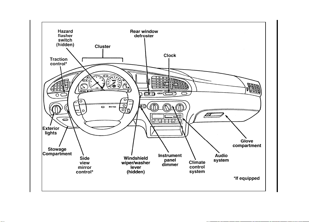
The instrument panel (dashboard) on your vehicle is divided
into several different sections. The illustrations on the following
pages show the major parts of the instrument panel that are
described in this chapter. Some items shown may not be on all
vehicles.
The main controls for the climate control system, clock, and
radio are on the instrument panel.
NOTE: Any cleaner or polish that increases the gloss (shine)
of the upper part of the instrument panel should be
avoided. The dull finish in this area is to help protect
the driver from undesirable windshield reflection.
7
Page 10
8
Page 11

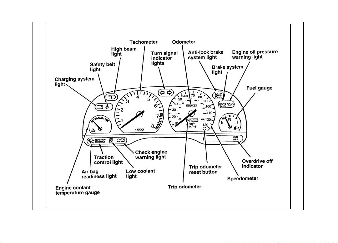
Instrumentation
In your vehicle, the warning lights and gauges are grouped
together on the instrument panel. We call this grouping a
cluster.
Your vehicle has a sport cluster.
9
Page 12
10
The sport cluster
Page 13
Instrumentation
The following warning lights and gauges are on the sport
cluster. All of the warning lights and gauges alert you to
possible problems with your vehicle. The following sections
detail what each of these indicators means.
Safety Belt Warning Light and Chime
This warning light and chime remind you to fasten your safety
belt. The following conditions will take place:
■ If the driver’s safety belt is not buckled when the ignition is
turned to the ON position, the light will turn on for 1 to 2
minutes and the chime will sound for 4 to 8 seconds.
■ If the driver’s safety belt is buckled while the light is on or
the chime is sounding, both the light and the chime will turn
off.
■ If the driver’s safety belt is buckled before the ignition is
turned to the ON position, neither the light nor the chime
will turn on.
11
Page 14
Brake System Warning Light
The warning light for the brakes can show two things — that
the parking brake is not fully released, or that the brake fluid
level is low in the master cylinder reservoir. If the fluid level is
low, the brake system should be checked by a qualified service
technician.
This light comes on when the parking brake is set, or if it is not
set, it comes on briefly when you turn the ignition to the
START position. It normally goes off shortly after the engine
starts and you release the parking brake. If the light stays on
after you have fully released the parking brake, have the
hydraulic brake system serviced by your dealer or a qualified
service technician.
RWARNING
The BRAKE light indicates that the brakes may not be
working properly. Have the brakes checked immediately.
12
Page 15
Instrumentation
Charging System Light
This light indicates that your battery is not being charged and
that you need to have the electrical system checked.
This light illuminates every time you turn the ignition to the
ON or START position (engine off). The light should go off
when the engine starts and the alternator begins to charge.
If the light stays on or illuminates when the engine is running,
have the electrical system checked as soon as possible.
Engine Oil Pressure Warning Light
This light indicates the engine’s oil pressure, not the oil level.
However, if your engine’s oil level is low, it could affect the oil
pressure. The light will come on briefly when you turn your
key to the START and ON position. The light should stay off
when the engine is running with normal oil pressure. If the
light comes on while the engine is running, you have lost oil
pressure and continued operation will cause severe engine
damage.
13
Page 16
If you lose engine oil pressure:
engine as soon as safely possible, severe engine damage
could result.
checking and adding engine oil in this Owner Guide. (See
Engine oil in the Index.) If you do not follow these
instructions, engine damage could result. To ensure an
accurate reading, your vehicle should be on level ground.
bring it to the full level before you start the engine again.
Do not overfill. Do not operate the engine if the light is on,
regardless of the oil level. Contact your nearest dealer for
further service actions.
High Beam Light
This light illuminates when the headlamps are turned to high
beam or when you flash the lights.
If the high beam light flashes in a vehicle equipped with the
Daytime Running Light (DRL) system (Canada), it indicates a
failure in the DRL circuit. Check the bulbs and fuses or have
the DRL system checked by your dealer or a qualified service
technician.
14
Page 17
Instrumentation
Chime for Headlamps On
This chime sounds if the driver’s door is open when the parking
lamps or headlamps are on. The chime sounds until you close
the door or turn off the lamps.
Air Bag Readiness Light
The air bag supplemental restraint system uses a readiness light
and a tone to indicate the condition of the system. The
readiness light is in the instrument cluster. When you turn the
ignition key to ON, this light will illuminate for approximately
six (6) seconds and then turn off. This indicates that the system
is operating normally. NOTE: Maintenance of the air bag system
is not required.
A problem with the system is indicated by one or more of the
following: the readiness light will either flash or stay lit, or it
will not light or a group of five beeps will be heard.
RWARNING
If any of these things happen, even intermittently, have
the air bag system serviced at your Ford or
Lincoln-Mercury dealer immediately.
15
Page 18
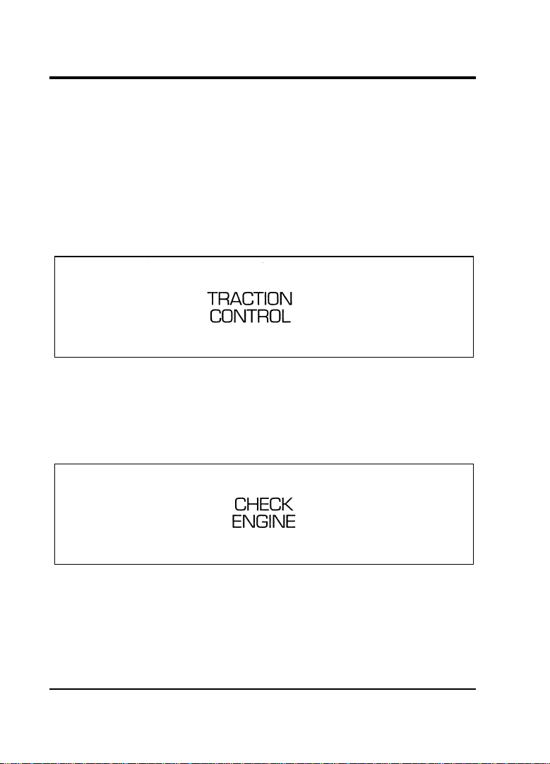
Traction Control System Light (If equipped)
This light comes on when the traction control system has been
disengaged. It may come on or flash on and off while traction
control is operating.
If the light stays on for more than three (3) seconds after the
ignition is turned to the ON position or does not come on when
the T/C OFF button is pressed, have the traction control system
checked by a qualified technician as soon as possible.
Check Engine Warning Light
This light illuminates when the engine’s Emission Control
System requires service. It will also illuminate when the ignition
key is in the ON position and the engine is off.
16
Page 19
Instrumentation
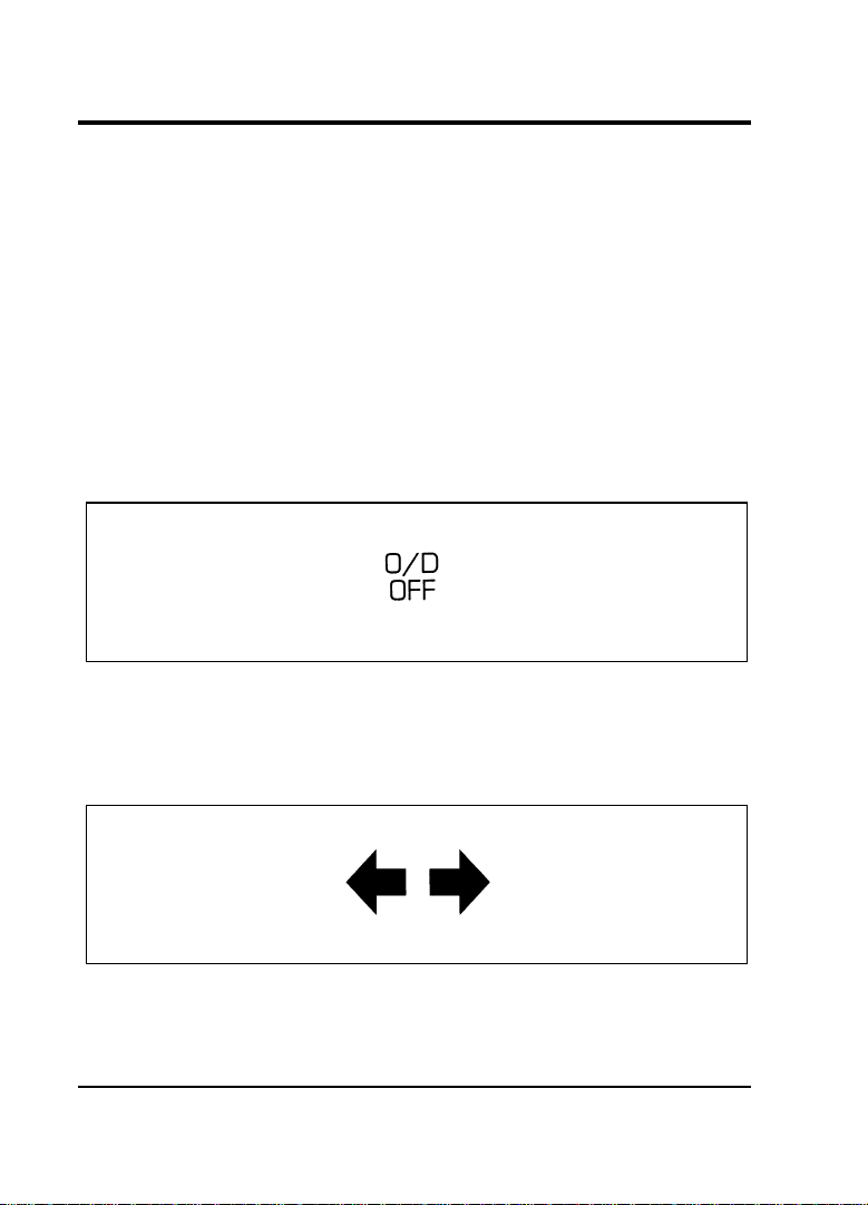
Overdrive Off Indicator (Automatic Transaxle Only)
This light tells you that the Transaxle Control Switch (TCS) on
the gearshift lever has been pushed. When the light is on, the
transaxle will not shift into overdrive. Depressing the TCS
button located below the gearshift release button on the shifter
will return the vehicle to “overdrive on” mode. The transaxle
will be in the “overdrive on” mode when the vehicle is started
even if the O/D OFF mode was selected when the vehicle was
last shut off.
If the light does not come on when the TCS is depressed or if
the light flashes when you are driving, have your vehicle
serviced at the first opportunity.
Turn Signal Indicator Lights
The turn signal arrow will flash to indicate the direction in
which you are going to be turning.
17
Page 20
Fuel Gauge
The fuel gauge displays approximately how much fuel you have
in the fuel tank.
For proper fuel gauge operation, the ignition must be in the
OFF position before you add fuel to the fuel tank.
The fuel gauge indicator may vary slightly while the vehicle is
in motion. This is the result of fuel movement within the tank.
An accurate reading may be obtained with the vehicle on
smooth, level ground.
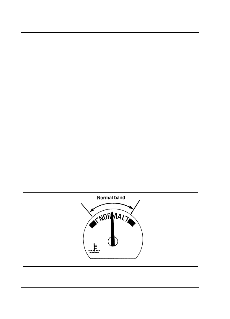
Engine Coolant Temperature Gauge
This gauge indicates the temperature of the engine coolant, not
the coolant level. If the coolant is not at its proper level or
mixture, the gauge indication will not be accurate.
The pointer moves from the white mark into the NORMAL
band as the engine coolant warms up. It is acceptable for the
pointer to fluctuate within the NORMAL band under normal
driving conditions. Under certain driving conditions, such as
heavy stop and go traffic or driving up hills in hot weather, the
pointer may indicate at the top of the NORMAL band.
The engine coolant temperature gauge
18
Page 21

Instrumentation
If, under any circumstances, the pointer moves above the
NORMAL band, the engine is overheating and continued
operation may cause engine damage.
If your engine overheats:
checking and adding coolant to your engine, see Engine
Coolant in the Index. If you do not follow these instructions,
you or others could be injured.
If the coolant continues to overheat, have the coolant system
serviced as soon as possible.
Speedometer
The speedometer tells you how many miles (kilometers) per
hour your vehicle is moving.
Odometer
The odometer tells you the total number of miles (kilometers)
your vehicle has been driven.
Trip Odometer
The trip odometer tells you how many miles (kilometers) your
vehicle has been driven since the last reset. Press the reset
control to return the trip odometer to zero.
Tachometer
The tachometer displays the approximate engine revolutions per
minute (rpm), or how fast the engine is running.
If you drive with the tachometer in the red zone, you may
damage the engine.
19
Page 22
Anti-lock Brake System Warning Light (If equipped)
Your vehicle may have an Anti-lock Brake System feature. If it
does, check the Anti-lock Brake System light each time you start
the engine. If it stays on longer than three (3) seconds, shut off
the engine and restart. If it stays on, that means the Anti-lock
Brake feature is not working and should be serviced
immediately to restore the benefits of the Anti-lock feature.
Normal braking is not affected unless the brake warning light is
also lit.
The Anti-Lock Brake System has self-check capabilities. As
described above, the system turns on the anti-lock light each
time you start your engine. After the engine is started and the
anti-lock light turns off, the system performs another test the
first time the vehicle reaches 5 mph (8 km/h) (between 12 and
25 mph [20 and 40 km/h] for vehicles equipped with the
traction control system). The system turns on the ABS pump
motor for approximately 1/2 second. At this time, a mechanical
noise may be heard and felt. This is a normal part of the
self-check feature. If a malfunction is found during this check
the anti-lock light will come on.
20
Page 23
Instrumentation
Low Coolant Light (If equipped)
This light indicates that the level of the engine coolant is low
inside the coolant recovery bottle and that you should add more
coolant. See Engine Coolant in the Index.
This light comes on for a few seconds when the ignition is
turned to the START position, but should turn off when the
engine starts. If this light stays on, check the level of coolant
inside the recovery bottle. The level may be slightly above the
MIN line because the light is an “early warning.”
21
Page 24
23
Compact Disc Radio
Electronic Sound Systems
Page 25

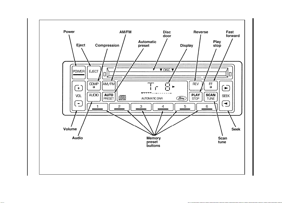
The Compact Disc Radio combines the Electronic Stereo Radio
with the Ford Compact Disc Player.
Using the Controls on Your New Radio/CD Player
Most of the features of this unit work for both radio and CD
operation. Also, some of the knobs and buttons control several
different functions, so be sure to read all of the operating
instructions carefully.
How to turn the radio on and off
Press the “POWER” button to turn the radio on. Press it again
to turn it off.
How to adjust the volume
Press the (R/S) side of the “VOL” button to increase/decrease
the volume. Bars illuminate in the display to show the relative
volume level.
NOTE: If the volume level is set above a certain listening
level when the ignition switch is turned off, when the
ignition switch is turned back on, the volume will
come back to a “nominal” listening level. However, if
the radio power is turned off, the volume will remain
in the position it was set at when radio power was
switched off.
Selecting the AM or FM frequency band
Push the “AM/FM” button to select the desired frequency band.
When in the radio mode, pushing the button more than once
will alternate between AM, FM1 and FM2. These functions are
used with the station memory buttons described under How to
tune radio stations.
24
Page 26

Electronic Sound Systems
How to tune radio stations
There are four ways for you to tune in a particular station. You
can manually locate the station using the “SCAN/TUNE”
button, “SEEK” the station, “SCAN” to the station or select the
station by using the memory buttons, which you can set to any
desired frequency. These four methods are described below.
■ Using the “SCAN/TUNE” button to manually tune
You can change the frequency up or down one increment at
a time (FM changes in increments of 200kHz; AM changes in
increments of 10kHz) by first pressing the “SCAN/TUNE”
button twice (display shows “TUNE”), then — within
approximately five seconds —pressing and releasing either
the top (a) or bottom (b) half of the “SEEK” button. To
change frequencies quickly, press and hold down either the
top or bottom half of the “SEEK” button. While you are
manually tuning, the display will show a blinking “M”.
Manual tuning adjusts your radio to any allowable broadcast
frequency, whether or not a station is present on that
frequency. (See All About Radio Frequencies in this section.)
■ Using the “SEEK” function
This feature on your radio allows you to automatically select
listenable stations up or down the frequency band. Press the
top (a) half of the “SEEK” button to select the next
listenable station up the frequency band. Press the bottom
(b) half of the button to select the next listenable station
down the frequency band. By pressing and holding the
button, listenable stations can be passed over to reach the
desired station.
25
Page 27

■ Using the “SCAN/TUNE” button to scan radio stations
Pressing the “SCAN/TUNE” button once enters the scan
mode (display will indicate “SCN”). Pushing the top (a)
half of the “SEEK” button will begin the scan mode up the
frequency band, stopping on each listenable station for
approximately five seconds. Pushing the bottom (b) half of
the “SEEK” button will begin the scan mode down the
frequency band, again stopping on each listenable station for
approximately five seconds.
To stop the scan mode on the presently sampled station,
press the “SCAN/TUNE” button again.
■ Setting the Station Memory Preset buttons
Your radio is equipped with 6 station memory buttons.
These buttons can be used to select up to 6 preset AM
stations and 12 FM stations (6 in FM1 and 6 in FM2).
until the sound returns. That station is now held in memory
on that button.
button you want to set.
NOTE: If the vehicle’s battery is disconnected, the clock and
station memory preset buttons will need to be reset.
■ Using the Automatic Memory Store feature
With Auto Memory Store, you can continually set strong
stations into your memory buttons without losing your existing
memory presets, which is especially handy while traveling. Your
radio will automatically set your memory buttons to the strong
local stations so you don’t have to continually manually tune to
existing stations.
26
Page 28

Electronic Sound Systems
Activate Auto Memory Store by pushing the “AUTO PRESET”
button once. Your radio will set the first five strong stations of
the band you are in (AM, FM1 or FM2) into the memory
buttons. The display will show “AUTO,” then run through the
frequencies, stopping momentarily on the stations being set into
the memory buttons. The radio is now in the “AUTO” mode
and the display will show “AUTO” each time a preset is
activated.
NOTE: If there are fewer than five strong stations in the
frequency band, the remaining unfilled buttons will
store the last strong station detected on the band.
After all stations have been filled, the radio will begin playing
the station stored on memory button 1.
To deactivate the Auto Memory Store mode and return to the
manually-set memory button stations (or those stations set using
Auto Memory Load), simply push the “AUTO PRESET” button.
Display will show “AUTO” then “OFF.” The next time Auto
Memory Store is activated on that band, the radio will store the
next set of five strong stations.
Adjusting the tone balance and speaker output of your
radio
■ Increasing or decreasing bass response
Push the “AUDIO” button repeatedly until the display reads
“BASS”. Push the top (+) of the “VOLUME” button to
increase bass (more “lows”), and push the button (s)to
decrease bass (less “lows”).
■ Increasing or decreasing treble response
Push the “AUDIO” button repeatedly until the display reads
“TREB”. Push the top (+) of the “VOLUME” button to
increase treble (more “highs”), and push the bottom (s)to
decrease treble (less “highs”).
27
Page 29

■ Adjusting speaker balance
Balance control allows you to adjust the sound distribution
between the right and left speakers. Push the “AUDIO”
button repeatedly until the display button reads “BAL”. Push
the top (+) of the “VOLUME” button to shift the sound to
the right speakers, and push the bottom (s) to shift the
sound to the left speakers.
■ Adjusting speaker fader
Fade control allows you to adjust the sound distribution
between the front and rear speakers. Push the “AUDIO”
button repeatedly until the display reads “FADE”. Push the
top (+) of the “VOLUME” button to shift the sound to the
front speakers, and push the bottom (s) to shift the sound
to the rear speakers.
NOTE: Illuminated bars in the display show relative levels of
bass and treble, and positions of speaker balance and
fader functions (left to right, front to rear).
28
Page 30
29
Ford Compact Disc Player
Electronic Sound Systems
Page 31

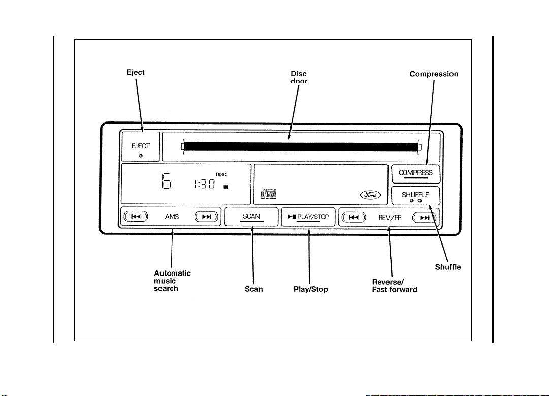
The Ford Compact Disc Player operates when the Audio System
is on and a disc is inserted (label side up). Handle the disc by
its edge only. (Be sure to read and follow all of the care and
cleaning instructions under How To Take Care of and Clean Your
CD Player and Discs in this section.)
The digital display on your CD player shows the track
(selection) number and the elapsed time. Indicators for playa,
stopX, compression on (“COMP”) and shuffle on (“SHUF”) are
also in the display. (These features are described later.)
Once a disc is inserted, operation of the CD player will override
that of the radio.
NOTE: The volume, bass, treble, balance and fader controls
on the radio are also used with the CD player. Refer
to earlier operating instructions on these controls.
How to insert a disc and begin play
Insert one disc, label side up into the disc opening. When
inserted, the disc automatically loads into the unit and play
starts at the beginning of the first track (selection).
When the disc reaches the end, the disc player automatically
returns to the beginning of the disc and resumes playing.
NOTE: Once a disc is inserted, the disc opening is secured to
prevent the accidental insertion of a second disc.
NOTE: The CD player has heat protection circuitry to protect
the laser diode. If the temperature of the player
reaches 167˚F (75˚C), the heat detection circuit will
shut off the player and “TOO HOT” will scroll in the
display for approximately five seconds (radio will
resume playing). When the temperature returns to
normal operating range, the CD player will again be
operational.
30
Page 32

Electronic Sound Systems
How to stop and restart the CD player
When a disc is loaded, the unit automatically enters the play
mode and the play indicator (a) illuminates. To stop
temporarily, press the “PLAY/STOP” button or the “AM/FM”
button. The stop indicator (X) in the display illuminates and
operation returns to the radio mode. To resume CD play, press
the “PLAY/STOP” button once again.
NOTE: If the ignition key is turned OFF during play and
then is set to the ON or ACCESSORY position, the
CD player will resume playing in the mode it was in
when ignition was turned off.
How to locate a selection on your CD player using
Automatic Music Search (AMS)
An “AMS” (Automatic Music Search) control on your CD player
allows you to quickly find a particular selection on the disc.
Press the left
previous selection or the right
to locate a later selection.
How to fast forward or reverse your CD player
To quickly search for a particular point in a selection, press the
right
reverse). While either button is pressed, the disc goes forward
or backward at two different speeds depending on how long the
button is held down. (Pressing either button for more than
approximately three seconds will speed up the process.) Release
the button at the desired point (found by watching the elapsed
playing time in the display or listening to the sound during fast
forward or reverse).
When you have reached the end of the disc by keeping the fast
forward
the end time of the last track and the sound will be muted.
When the fast forward
player resumes play at the beginning of the first track.
button (to fast forward) or the left
e
e
side of the “AMS” control to locate a
f
side of the button pressed, the display will show
side of the button is released, the
e
side of the “AMS” control
e
f
button (to
31
Page 33

A “1” and “0:00” will appear in the display when the beginning
of the disc is reached by pressing the rewind
button.
f
side of the
Using the “SCAN” function
Press the “SCAN” button to enter the scan mode. The CD
player will begin scanning the disc, stopping on each listenable
track for approximately eight seconds. This continues until you
press the “SCAN” button a second time or eject the disc. While
in the scan mode, the display flashes “SCAN.”
Special features of your CD player
■ Compression
The compression feature will bring soft and loud passages
closer together for a more consistent listening level.
To turn the compression on, press the “COMPRESS” button.
When on, the compression indicator (“COMP”) will appear
in the display. Press the button again to turn off.
■ Shuffle
The shuffle feature on your CD player allows you to listen
to your disc selections in a different order. When this feature
is activated, your CD player will randomly select and play
tracks on the disc.
Press the “SHUFFLE” button to turn on, press it again to
turn off. When on, the shuffle indicator (“SHUF”) will
appear in the display. When the player is between selections,
the display will show a moving dash (s) around the
perimeter of the display.
32
Page 34

Electronic Sound Systems
■ Shuffle and Scan
Both the shuffle and scan features can be activated
simultaneously. In this mode, the player will randomly pick
a selection and play the first eight seconds. This process is
continued until either the “SCAN” button or “SHUFFLE”
button is pressed a second time.
■ Automatic Disc Storage
If the disc is ejected from the CD player but is not removed
from the disc opening within approximately 10 seconds, the
player will automatically reload the disc for storage, unless
the disc is automatically ejected due to a “focus error” (disc
inserted upside down). In this case, the disc will not be
automatically reloaded.
How to eject the disc
Push the “EJECT” button in the upper left corner of your CD
player to stop play, eject the disc and resume radio or tape
operation of your audio system.
How To Take Care of and Clean Your CD Player and
Discs
To ensure the continued performance of your Ford Compact
Disc Player, carefully read the following precautions:
■ Always handle the disc by its edge. Never touch the playing
surface.
■ Before playing, inspect the disc for any contamination. If
needed, clean the disc with an approved disc cleaner, such as
the DiscwasherH Compact Disc Cleaner or the Allsop 3H
Compact Disc Cleaner, by wiping from the center out to the
edges. Do not use a circular motion to clean.
■ Do not clean discs with solvents such as benzine, thinner,
commercially available cleaners or antistatic spray intended
for analog records.
33
Page 35

■ Do not expose the disc to direct sunlight or heat sources
such as defroster and floor heating ducts. Do not leave any
discs in a parked car in direct sunlight where there may be a
considerable rise in temperature or damage may result.
■ After playing, store the disc in its case.
■ If a disc has already been inserted, do not try to insert
another disc. Doing so may damage the disc player.
■ Do not insert anything other than a disc into the disc player.
CAUTION: The use of optical instruments with this product
will increase eye hazard as the laser beam used in this compact
disc player is harmful to the eyes. Do not attempt to
disassemble the case. Refer servicing to qualified personnel only.
Common Operating Conditions of Your CD Player
The following information is designed to help you recognize
typical situations that could be mistakenly interpreted as
mechanical malfunctions of the disc player.
■ A disc is already loaded.
■ The disc is inserted with the label surface downward.
■ The disc is dusty or defective.
■ The player’s internal temperature is above 167˚F (75˚C).
Allow the player to cool off before operating.
■ Different manufacturers of compact discs may produce discs
with different dimensions or tolerances, some of which may
not be within industry standards or in accordance with the
CD format. Because of this, a new disc that is free of dust
and scratches could be defective and may not play on your
Ford Compact Disc Player.
34
Page 36

Electronic Sound Systems
If play does not begin after the CD button is pushed:
■ The radio is not on.
■ The unit is in the stop mode.
■ Moisture may have condensed on the lenses within the unit.
If this occurs, remove the disc and wait approximately an
hour until the moisture evaporates.
If the sound skips:
■ Badly scratched discs or extremely rough roads will cause
the sound to skip. Skipping will not damage the disc player
or scratch the discs.
35
Page 37

36
Electronic Stereo Radio
Page 38

37
Electronic Stereo Radio with Cassette
Electronic Sound Systems
Page 39

Radios
Both the Electronic Stereo Radio and Cassette Radio offer full
electronic tuning with new soft touch controls.
Using the Controls on Your New Radio
How to turn the radio on and adjust the volume
Press the “POWER” button to turn the radio on. Press it again
to turn it off.
Press the right (+) side of the “VOLUME” button to increase the
volume. Press the left (s) side of the button to decrease the
volume. Illuminated bars in the display show the relative
volume level.
NOTE: If the volume level is set above a certain listening
level when the ignition switch is turned off, when the
ignition switch is turned back on, the volume will
come back to a “nominal” listening level. However, if
the radio power is turned off, the volume will remain
in the position it was set at when radio power was
switched off.
Selecting the AM or FM frequency band
Push the “AM/FM” button to select the desired frequency band.
Pushing the button more than once will alternate between AM,
FM1 and FM2. These functions are used with the station
memory buttons described under How to tune radio stations.
38
Page 40

Electronic Sound Systems
How to tune radio stations (Stereo Radio)
■ Using the “TUNE” function
You can change the frequency up or down one increment at
a time by pressing and releasing either the right (+) or left
(s) side of the “TUNE” button. To change frequencies
quickly, press and hold down either the right or left side of
the “TUNE” button.
Manual tuning adjusts your radio to any allowable broadcast
frequency, whether or not a station is present on that
frequency. (See All About Radio Frequencies in this section.)
■ Using the “SEEK” function
This feature on your radio allows you to automatically select
listenable stations up or down the frequency band. Press the
right (a) side of the “SEEK” button to select the next
listenable station up the frequency band. Press the left (b)
side of the button to select the next listenable station down
the frequency band. By holding the button down, listenable
stations can be passed over to reach the desired station.
How to tune radio stations (Stereo Cassette Radio)
■ Using the “AMS” function to manually tune your radio
(Stereo Cassette Radio)
You can change the frequency up or down one increment at
a time by first pressing the “AMS” button (display shows
“TUNE”) then within approximately five seconds pressing
and releasing either the rightaor leftbside of the
“SEEK” button. To change frequencies quickly, press and
hold down either the right or left side of the “SEEK” button.
Manual tuning adjusts your radio to any allowable broadcast
frequency, whether or not a station is present on that
frequency. (See All About Radio Frequencies in this section.)
39
Page 41

■ Using the “SEEK” function
This feature on your radio allows you to automatically select
listenable stations up or down the frequency band. Press the
right (a) side of the “SEEK” button to select the next
listenable station up the frequency band. Press the left (b)
side of the button to select the next listenable station down
the frequency band. By holding the button down, listenable
stations can be passed over to reach the desired station.
■ Using the “SCAN” function (Stereo Cassette Radio)
Press the “SCAN” button to enter the scan mode. The radio
will begin scanning up the frequency band, stopping on each
listenable station for approximately a five-second sampling.
This continues until you press the “SCAN” button a second
time. The display flashes “AM” or “FM.”
■ Setting the Station Memory Preset buttons
Your radio is equipped with 6 station memory buttons.
These buttons can be used to select up to 6 preset AM
stations and 12 FM stations (6 in FM1 and 6 in FM2).
Follow the easy steps below to set these buttons to the desired
frequencies:
until the sound returns. That station is now held in memory
on that button.
button you want to set.
NOTE: If the vehicle’s battery is disconnected, the clock and
station memory preset buttons will need to be reset.
40
Page 42

Electronic Sound Systems
Adjusting the tone balance and speaker output of your
radio
■ Increasing or decreasing bass response
Push the “AUDIO” button repeatedly until the display reads
“BASS.” Push the right (+) side of the “VOLUME” button to
increase bass (more “lows”), and push the left (s) side to
decrease bass (less “lows”).
■ Increasing or decreasing treble response
Push the “AUDIO” button repeatedly until the display reads
“TREB.” Push the right (+) side of the “VOLUME” button to
increase the treble (more “highs”), and push the left (s) side
to decrease treble (less “highs”).
■ Adjusting speaker balance
Balance control allows you to adjust the sound distribution
between the right and left speakers. Push the “AUDIO”
button repeatedly until the display reads “BAL.” Push the
right (+) side of the “VOLUME” button to shift the sound to
the right speakers, and push the left (s) side to shift the
sound to the left speakers.
■ Adjusting speaker fader
Fade control allows you to adjust the sound distribution
between the front and rear speakers. Push the “AUDIO”
button repeatedly until the display reads “FADE.” Push the
right (+) side of the “VOLUME” button to shift the sound to
the front speakers, and push the left (s) side to shift the
sound to the rear speakers.
NOTE: Illuminated bars in the display show relative levels of
bass and treble, and positions of speaker balance and
fader functions (left to right, front to rear).
41
Page 43

Using the Controls of Your Cassette Tape Player
NOTE: Radio power must be on to use the cassette tape
player.
How to insert a tape
Insert a cassette (with the open edge to the right) firmly into the
tape door opening, making sure the cassette is completely in
and “seated.”
How to locate a desired track on the tape
NOTE: The tape track or side number indicated in the display
does not necessarily correspond to the tape track or
side number on the cassette label. It is used only to
indicate when the tape mechanism reverses tracks.
■ Using the Automatic Music Search (“AMS”)
Press and hold the “AMS” button (“AMS” will appear in the
display). Then, push the left
beginning of the current selection or press the right
to fast forward to the beginning of the next selection.
button to rewind to the
h
g
button
■ Fast forwarding the tape
Push the right
button to fast forward the tape.
g
■ Rewinding the tape
Push the left
button to rewind the tape.
h
■ How to change the side of the tape being played
The alternate track (other side) of the tape can be selected at
any time by pushing both fast-wind buttons
at the same time.
42
h
and
g
Page 44

Electronic Sound Systems
How to eject the tape
To stop the tape and eject the cassette, press the eject (i)
button. The radio will resume playing.
Using the DolbyH B noise reduction feature
NOTE: Noise reduction system manufactured under license
from Dolby Labs Licensing Corporation. “Dolby” and
double-D symbol are trademarks of Dolby
Laboratories Licensing Corporation.
Push station memory button 3 to activate DolbyH B Noise
Reduction.
Tips on Caring for the Cassette Player and Tapes
In order to keep your cassette tape player performing the way it
was meant to, read and follow these simple precautions:
■ Using a Ford Cassette Cleaning Cartridge or equivalent to
clean the tape player head after 10-12 hours of play will help
maintain the best playback sound and proper tape operation.
■ Only cassettes that are 90 minutes long or less should be
used. Tapes longer than 90 minutes are thinner and subject
to breakage or may jam the tape player mechanism.
■ Protect cassettes from exposure to direct sunlight, high
humidity and extreme heat or cold. If they are exposed to
extreme conditions, allow them to reach a moderate
temperature before playing.
■ If a tape is loose inside the cassette, tighten it before playing
by putting your finger or a pencil into one of the holes and
turning the hub until the tape is tight.
■ Loose labels on cassette tapes can become lodged in the
mechanism. Remove any loose label material before inserting
a cassette.
43
Page 45

■ Do not leave a tape in the cassette tape player when not in
use. High heat in the vehicle can cause the cassette to warp.
Using the Power Antenna
The power antenna will automatically rise when your radio is
turned on and the ignition is in the ON or ACC position. It will
lower when either the radio or the ignition is turned off.
Power antenna maintenance and care
■ Never drive your vehicle through a car wash with the power
antenna mast extended. This can cause damage to the
antenna mast, which is not covered under warranty. Turn off
your radio and/or the vehicle. This will automatically retract
the antenna.
■ If your power antenna mast ever becomes damaged, the
mast may not extend or retract properly which might limit
reception performance. In this case, it is not necessary to
replace the entire power antenna assembly. A replacement
mast can be obtained from your dealership for a nominal fee.
■ Occasionally, the power antenna mast should be wiped clean
with mild soap and water or denatured alcohol. This
prevents debris from accumulating on the mast which can
cause excessive wear and decrease the power antenna life.
Never use petroleum-based products to clean your antenna
mast.
Several conditions prevent FM reception from being completely
clear and noise-free, such as the following:
The strength of the FM signal is directly related to the distance
the signal must travel. The listenable range of an average FM
signal is approximately 25 miles (40 kilometers). Beyond this
distance, the radio is operating in a fringe area and the signal
becomes weaker.
44
Page 46

Electronic Sound Systems
The terrain (hilly, mountainous, tall buildings) of the area over
which the signal travels may prevent the FM signal from being
noise-free.
Some FM radio stations advertise a “rounded-off” frequency
which is not the frequency they actually broadcast on. For
example, a radio station that is assigned a frequency of 98.7
MHz may call itself “Radio 99” even though 99.0 MHz is not an
allowable FM broadcast frequency.
■ Warranty
Your sound system is warranted for three years or 36,000 miles
(60,000 kilometers), whichever comes first. Consult your vehicle
warranty booklet for further information. Ask your dealer for a
copy of this limited warranty.
■ Service
At Ford, we stand behind our audio systems with a
comprehensive service and repair program. If anything should
go wrong with your Ford audio system, return to your dealer
for service. There is a nationwide network of qualified Ford
authorized repair centers to assist you.
45
Page 47

Controls and Features
Your vehicle has one of the following:
■ Heating Only System (Without Air Conditioning)
■ Heating and Air Conditioning System
If you are not sure which system your vehicle has, see the
diagrams on the following pages.
Heating Only System
The control for your heater system is located at the center of the
instrument panel below the radio. The heater will operate only
when the ignition key is turned to the ON position. Your heater
will heat and/or ventilate your vehicle interior depending on
the function selector knob position and temperature you select.
The function selector knob allows you to select heating or
ventilation and determine where the air will be directed. The
temperature control knob setting determines the temperature of
the air that flows into the vehicle.
The control for the heating only system
To turn your heater system on, select any position except OFF.
This will turn the fan on and allow air flow into the vehicle. To
turn your heater off, select OFF. This will turn the fan off and
stop air flow from coming into the vehicle.
47
Page 48

Your vehicle also has small demister openings on each front
door near the window. This allows a small amount of air flow
to be directed onto the door glass to reduce fogging whenever
the heater system is operating.
The temperature control is located at the right side of the
control with a broken RED and BLUE band around the top and
sides. The all RED part of the band (full right) is the heat or
warmer area. The all BLUE area (full left) is the cool or
unheated temperature area. Any position selected between full
right and full left will give a temperature between the two
extreme temperatures. The cool temperature you select will not
be cooler than the outside temperature if your vehicle is not
equipped with an air conditioner.
Fan speed adjustment
H
TheH(left) control is the fan speed control which controls the
volume of air flow. Rotate theHcontrol to HI to increase fan
speed and increase the amount of air entering the vehicle. Four
fan speed positions are available and are indicated by LO, two
single dots and HI beside theHcontrol.
Air flow selections
PANEL
Use PANEL to bring outside air through the instrument panel
registers. You can heat the air in this position by rotating the
temperature control into the RED area. The air CANNOT be
cooled below the outside temperature regardless of the
temperature control setting.
PNL/FLR
Select PNL/FLR to get air flow to the floor and through the
instrument panel registers at the same time. This selection can
be used to either heat or ventilate your vehicle.
FLOOR
Air flow will be to the floor when FLOOR is selected. The air
cannot be cooled in the FLOOR position but can be heated by
rotating the temperature control knob into the RED area.
48
Page 49

Controls and Features
FLR/DEF
Select FLR/DEF to get air to the floor and windshield defrosters
at the same time.
V DEF
Select V DEF to obtain maximum air flow to the windshield.
Rotate the temperature control into the RED area for the air
temperature required to defrost. Rotate theHcontrol to
increase the air flow.
Heating and Air Conditioning System
Heating, ventilation, defrosting and defogging are accomplished
in the same way as with the heating only system. See “Heating
Only System.”
With the heating and air conditioning system, if the outside
temperature is about 50˚F (10˚C) or warmer, the air will be
dehumidified to remove moisture if you select FLR/DEF or V
DEF.
The control for the heating and air conditioning system
49
Page 50

Air conditioning
A/C
Select A/C to get refrigerated outside air through the
instrument panel registers. The A/C position is used for cooling
except when extremely hot or fast cooling of the vehicle is
needed. Then, select MAX A/C for fast cooling and return to
A/C when you are comfortable.
MAX A/C
The MAX A/C position produces cool air more rapidly to
provide faster cooling of your vehicle. This is possible because
cooler air is drawn from inside the passenger area and
refrigerated again instead of using warmer outside air. Using
inside air will also make the fan sound louder, which is normal
when using MAX A/C. The air flow will be from the
instrument panel registers.
Comfort tips
The following tips will help you to get the most satisfaction
from your climate control system.
■ In humid weather, select V DEF before starting your
engine. This will help to prevent windshield fogging. After a
few minutes of operation, you may select another function.
■ To prevent humidity buildup inside your vehicle, always
drive with the climate control system turned on.
■ Do not put objects under the front seats that interfere with
the flow of air to the back seat area.
■ Remove any snow, ice, or leaves from the air intake area of
your heater and air conditioner system which could block
the air intake. The intake area is located at the bottom of the
windshield.
50
Page 51

Controls and Features
Passenger Compartment Air Filter (if equipped)
Your vehicle may have an air filter that removes pollen and
road dust from outside air before it is directed to the interior of
the vehicle. For maintenance of this filter, see the Maintenance
and Care chapter.
The defroster for the rear window clears frost, fog, or thin ice
from both the inside and outside of the rear window.
The button for the rear window defroster is on the instrument
panel, to the right of the steering wheel.
The rear window defroster and heated side view mirrors
Clear away any snow that is on the rear window before using
the defroster. With the engine running, push the defroster
button.
After approximately 10 minutes, the defroster will turn off. If
the window is still not clear, turn the defroster on again.
The defroster will turn off when the ignition key is turned to
the OFF or START position.
51
Page 52

NOTE: Never use sharp instruments or window cleaners with
abrasives to clean the inside of your rear window. If
you do, you may damage the heating elements that
are bonded to the inside of the rear window and
cause damage to the rear window defroster.
Turning On the Exterior Lights
To turn on your headlamps, parking lamps, and tail lamps, use
the knob that is on the instrument panel, to the left of the
steering wheel.
The knob for the exterior lights
To turn on the parking lamps, tail lamps, license plate lamps
and side marker lamps, turn the knob clockwise to the first
position.
To turn on the headlamps, parking lamps, tail lamps, license
plate lamps and side marker lamps, turn the knob clockwise to
the second position.
52
Page 53

Controls and Features
Fog Lamps (If equipped)
The fog lamps act as a supplement to the low beam headlamps
under limited visibility conditions such as rain, snow, dust or
fog.
The fog lamps operate only when the low beam headlamps are
on. To operate the fog lamps, turn the headlamp control knob
to the second position (headlamps on) and pull the knob out.
An indicator lamp will glow when the fog lamps are on.
To turn off, push the headlamp control knob in.
To maximize fog lamp bulb life, it is recommended that the fog
lamp switch be turned off after each use prior to turning off the
headlamps.
Daytime Running Light System
(Canadian vehicles only)
The Daytime Running Light (DRL) system is designed to turn
the high beam headlamps on, with a reduced light output and
without illuminating the high beam indicator lamp in the
instrument panel. The DRL system operates when all of the
following conditions are met:
■ The vehicle’s parking brake is fully released.
■ The vehicle is “running.”
■ The headlamp system is in the OFF position.
The high beam indicator light on the instrument cluster will not
be on.
A flashing high beam light in the instrument cluster indicates a
failure in the DRL system circuit, like a burnt bulb or fuse.
53
Page 54

RWARNING
The Daytime Running Light (DRL) system will not
illuminate the tail lamps and parking lamps. Turn on
your headlamps at dusk. Failure to do so may result in a
collision.
Lighting Up the Interior and Instrument Panel
When either front door is opened, the footwell lights and the
door courtesy lights come on.
The instrument panel lights, window control lights and door
handle lights come on whenever the headlamp switch is turned
from the OFF position. To dim the instrument panel lights, use
the thumbwheel on the instrument panel to the right of the
steering wheel.
Dimming the instrument panel lights
This button turns the traction control system off and on. See the
Driving Chapter for more information.
The button for the traction control system
54
Page 55

Controls and Features
The digital clock
desired hour appears, release the button.
the desired minute appears, release the button.
press both the hour and minute buttons at the same time.
Reset the time as above.
Your vehicle may have several storage compartments:
■ a coin holder on the instrument panel
■ a stowage compartment on the lower left side of the
instrument panel
The controls on the steering column and wheel are designed to
give you easy access to the controls while you are driving.
55
Page 56

Understanding the Positions of the Ignition
The positions of the key in the ignition
LOCK and ACCESSORY lock the gearshift for all vehicles with
an automatic transaxle.
RWARNING
LOCK position does not lock the gearshift on
floor-mounted manual transaxle gearshifts. If the parking
brake is not set and the gearshift is moved out of gear,
your vehicle may move unexpectedly and injure someone.
The automatic transaxle gearshift must be in P (Park) to move
the key to the LOCK position.
LOCK is the only position that allows you to remove the key.
The LOCK feature helps to protect your vehicle from theft.
If your key is stuck in the LOCK position and will not turn,
move your steering wheel left or right until the key turns freely.
ACCESSORY allows some of your vehicle’s electrical accessories
to operate while the engine is not running. For example, you
56
Page 57

Controls and Features
can use ACCESSORY to turn on the radio without starting the
engine.
ON allows you to test your vehicle’s warning lights (except the
brake system warning light) to make sure they work before you
start the engine. The key returns to the ON position once the
engine is started and remains in this position while the engine
runs.
START cranks the engine. Release the key once the engine starts
so that you do not damage the starter. The key should return to
ON when you release it. The START position also allows you to
test the brake warning light.
Removing the Key From the Ignition
Procedures for removing your key from the ignition vary,
depending on whether your vehicle has an automatic or manual
transaxle.
If your vehicle has an automatic transaxle:
If your vehicle has a manual transaxle:
The steering wheel locks when the key is removed.
57
Page 58

If the driver’s door is open while the key is still in the ignition,
a warning chime sounds.
RWARNING
Always set the parking brake fully and make sure that
the gearshift is securely latched in P (Park) (automatic
transaxle) or in 1 (First) (manual transaxle).
RWARNING
Do not leave children, unreliable adults, or pets
unattended in your vehicle.
58
Page 59

Controls and Features
You can use the turn signal lever on the left side of the steering
column to:
■ operate the turn signals and cornering lamps
■ turn the high beams on/off
■ flash the lamps
Turn Signals
The turn signal lever
Move the lever up to signal a right turn. Move it down to
signal a left turn. The corresponding indicator light in the
instrument cluster will flash.
If the turn signal stays on after you turn, move the lever back
to the center (off) position.
For lane changes, move the lever far enough to signal but not to
latch. The lever will return to the off position when you release
it.
59
Page 60

High Beams and Flashing the Lamps
To turn on the high beams, turn the headlamp control knob to
the headlamp ON position and push the turn signal lever away
from you until it latches. When the high beams are on, the high
beam indicator light on the instrument cluster comes on.
To turn off the high beams, pull the lever back to the off
position.
To flash the headlamps, pull the lever toward you for a moment
and then release it. The headlamps will flash whether the
headlamp knob is in the on or off position.
To turn on the windshield wipers, the ignition key must be
turned to the ON position.
Using the windshield wiper
The windshield wipers can be set on high, low speed or interval
wipe. Turn the ring on the lever to set a longer or shorter pause
between wiping cycles.
60
Page 61

Controls and Features
Windshield Washer
When the lever is pulled to activate the windshield washer, the
wipers operate for about three cycles after the spray stops.
Washing the windshield
Do not try to clean the windshield when the washer fluid
container is empty or activate the washers at any time for more
than 15 seconds continuously. This could damage the washer
pump system.
RWARNING
Always warm up the windshield with the defroster
before you use the washer fluid. In freezing weather, the
washer solution may freeze on the windshield and
obscure your vision.
For information about refilling the washer fluid or replacing
your windshield wiper blades, see Windshield washer fluid and
Wipers in the Index.
61
Page 62

The hazard flasher serves as a warning to other drivers to be
careful when approaching or passing your vehicle.
Using the hazard flasher switch
To sound the horn, push the pad in the center of the steering
wheel. Check the horn regularly to be sure it operates properly.
62
Page 63

Controls and Features
RWARNING
Never adjust the steering column/wheel when the vehicle
is moving. You could lose control of the vehicle and
injure someone.
The lever to tilt the steering wheel
To change the position of the steering wheel, pull down the
knob on the bottom left-hand side of the column to extend the
lever. Pull the lever toward you, unlocking the column.
Move the steering wheel up or down until you find the position
you prefer. Push the lever away from you, locking the column
in position. When you release the knob, the lever will retract.
63
Page 64

The speed control switches on the steering wheel
To Turn Speed Control On
Press the on button.
The speed of the vehicle cannot be automatically controlled until
the vehicle speed is at or above 30 mph (48 km/h).
RWARNING
Do not use the speed control in heavy traffic or on roads
that are winding, slippery, or unpaved.
RWARNING
Do not shift to N (Neutral) with the speed control on.
To Turn Speed Control Off
Press the OFF switch.
To Set a Speed
With the speed control on, press the Set Accel switch to set and
store the instantaneous vehicle speed.
64
Page 65

Controls and Features
If you drive up or down a steep hill, your vehicle may
momentarily slow down or speed up, even though the speed
control is on. This is normal.
NOTE: If your vehicle is equipped with an automatic
transaxle, and if your speed increases above your set
speed while driving in Overdrive on a downhill
grade, you may want to turn the Overdrive off and
use Drive. You may turn the Overdrive off by
pressing the Transaxle Control Switch on the left side
of the gearshift lever. This will reduce vehicle speed
if it goes above your set speed on a downhill grade.
NOTE: If your vehicle is equipped with a 5-speed manual
transaxle, and if your speed increases above your set
speed while driving in 5 (Fifth) gear on a downhill
grade, you may want to shift to 4 (Fourth) gear to
reduce vehicle speed. Depressing the clutch pedal
cancels speed control, therefore speed control must be
reset by pressing the SET/ACC or RES buttons. Speed
control cannot reduce the vehicle speed if it goes
above your set speed on a downhill grade.
To Speed Up
Hold the Set Accel switch down and the vehicle will speed up
without the need to depress the accelerator. When the switch is
released, the system will maintain the speed reached. This speed
becomes the new stored speed.
The vehicle speed can also be increased by momentarily
depressing the Set Accel switch (Tap up). Each tap will increase
the speed by approximately 1 mph (1.6 km/h).
To Slow Down
Hold the Coast switch down and the vehicle will slow down
under normal engine braking. When the switch is released, the
system will maintain the speed reached. This speed becomes the
new stored speed.
65
Page 66

The vehicle speed can also be decreased by momentarily
depressing the Coast switch (Tap down). Each tap will decrease
the speed by approximately 1 mph (1.6 km/h).
Resume feature
The speed control system will be disengaged as soon as the
brake or clutch pedal is depressed. To turn to the previously set
speed, momentarily depress the RES switch.
Your vehicle has two dome lamps, one above the front seat and
one above the back seat. The switch on the dome lamp turns
that dome lamp on and off.
The switches on the dome lamp (front lamp shown, rear lamp similar)
Dome lamp delay
Your vehicle may have a dome lamp delay. If you set the
switch on the dome lamp to the 12-second delay position, the
dome lamp will turn on when either front door is opened.
The dome lamp will turn off after 12 seconds or when the
ignition key is turned to the ON or ACC position. It will not
turn off if either front door is open or if you move the dome
lamp switch to the ON position.
Your interior dome lamps and map lamps are plastic and
should be cleaned with a mild detergent diluted in water. Rinse
them with clear water.
66
Page 67

Controls and Features
Your vehicle may have a map lamp for the passenger and one
for the driver.
Turning on the map lamps
You can move the moon roof back to open the glass panel, or
you can tilt it up to ventilate the vehicle.
The rocker type switch is used to open and close the moon roof.
You must press and hold the switch until the desired position is
reached. At open and closed positions, the motor will
automatically turn off. Release the switch at this time to avoid
motor damage.
67
Page 68

The map lamps and the switch for the moon roof
To open the moon roof, press and hold the rear portion of the
switch. The glass panel will move to the open position and stop.
To close the moon roof, press and hold the front portion of the
switch. The glass panel will move to the closed position and
stop.
To tilt the moon roof into vent position when the glass panel is
closed, press the front portion of the switch.
To close from vent position, press and hold the rear portion of
the switch.
Occasionally wiping the outside guide rail covers of the moon
roof with a clean cloth will help keep the moon roof working
properly.
68
Page 69

Controls and Features
The moon roof
RWARNING
Do not let children play with the moon roof. They may
seriously hurt themselves.
Sliding Shade
The moon roof has a sliding shade that you can manually open
or close to block the sun when the glass panel is shut.
To close the sliding shade, pull the shade toward the front of
the vehicle. The shade automatically opens when the moon roof
is opened.
69
Page 70

Illuminated Visor Mirror (If equipped)
Your vehicle may have lighted mirrors on the sun visors. The
mirror is lit by sliding open the mirror cover.
The visor mirror
Childproof Locks for the Rear Doors
In addition to standard or power locks, your vehicle has
childproof locks for the rear doors. If you set these locks, the
rear doors cannot be opened from the inside of the vehicle. The
doors can still be opened from the outside if the doors are
unlocked.
70
Page 71

Controls and Features
The childproof locks for the rear door
To set the childproof lock on each rear door, open the rear
door.
Find the lever at the black label with word LOCKED in white
letters. Move the lever toward the inside of the door.
To release the childproof lock, open the rear door from the
outside.
Move the lever toward the outside of the door.
Power Door Locks (If equipped)
If your vehicle has power door locks, the controls to lock the
doors are on the trim panel of the front door. When you close
the doors after you set the door locks, the doors remain locked.
If the power mechanism fails, the manual door lock will
automatically override the power controls.
71
Page 72

The power door lock on the driver’s door
Power Windows (If equipped)
Each door has a power control that opens and closes the
window on that door. The driver’s door has a master control
panel that operates all four windows.
In order to use your power window controls, the ignition switch
must be in the ON position.
72
Page 73

Controls and Features
The master controls on the driver’s door
RWARNING
Do not let children play with the power windows.
One-touch-down window
The one-touch-down feature allows you to completely open the
driver’s window by briefly pressing and releasing the bottom of
the window switch. To stop the window before it opens
completely, press the switch again.
The one-touch feature only opens the window. To close the
window, you must press and hold the top of the switch.
Rear window lockout
To lock out the rear window switches with the master controls,
slide the lockout switch to the left. To restore individual control,
slide the switch to the right.
73
Page 74

Side View Mirrors
The standard side view mirrors are manually adjusted by using
the remote knobs. The knob on each door adjusts the mirror on
that side of the vehicle. Move the control knob in the direction
you want to move the mirror.
The left side mirror control (right side similar)
Dual electric remote control mirrors (if equipped)
The control for adjusting the electric side view mirrors is on the
instrument panel, to the left of the steering wheel.
74
Page 75

Controls and Features
Electric remote control mirror knob
Turn the knob back to the middle position to keep the mirror in
place.
The side view mirror on the right is a convex mirror. This
mirror gives you a wider view of the lanes on your right and
behind you.
RWARNING
The right side view mirror makes objects appear smaller
and farther away than they actually are.
Do not clean the housing or glass of any mirror with harsh
abrasives, fuel or other petroleum-based cleaning products.
75
Page 76

Your vehicle may have a full console. The full console has the
following features:
The features on the full console
Cupholder with Full Console
To raise the pop-up cup holder, push and release the cupholder
door, then unfold the holder.
76
Page 77

Controls and Features
Positive retention floor mat (If equipped) (Standard in
Canada)
Position the floor mat in the footwell. Place the mat eyelet over
the pointed end of the retention post from the rear and rotate
forward to install. Adjust the floor mat position to allow proper
operation of accelerator pedal, brake pedal and clutch pedal.
The positive retention floor mat
To remove, lift the floor mat just forward of the retention post
and rotate it rearward to disengage it from the retention post.
77
Page 78

To open the trunk manually, use the oval key.
Remote Trunk Release (If equipped)
The remote trunk release is on the floor to the left of the
driver’s seat.
The remote trunk release
You can disable the remote trunk release. If you depress the
lever on the trunk latch that is marked in orange before closing
the trunk, the trunk can only be opened with the key.
Disabling the remote trunk release
78
Page 79

Controls and Features
If your vehicle has the remote entry system, you can lock and
unlock the vehicle doors and open the trunk without using a
key. The remote also has a personal alarm feature. The controls
for the system are located on the hand held transmitter(s) that
came with your vehicle.
The system will work with up to four transmitters. Additional
transmitters can be ordered from your dealer.
The remote entry features only operate with the ignition in the
OFF position.
Remote entry transmitter
79
Page 80

Unlocking the doors and opening the trunk
To unlock the driver’s door, press the UNLOCK control.
To unlock the other doors, press the UNLOCK control a second
time within five seconds of unlocking the driver’s door.
To open the trunk, press the TRUNK control.
When you use the remote entry UNLOCK, TRUNK or PANIC
controls, the illuminated entry system turns on the interior
lights for 12 seconds. You can turn these lights off by turning
the ignition to the ON position. The interior lights will not turn
off if you have turned them on manually or if a door is open.
NOTE: The illuminated entry system will only work when
the dome light switch is in the “12” position.
Locking the doors
To lock all the doors, press the LOCK control.
If you would like a signal that the doors are being locked, press
the LOCK control again within five seconds. The doors will lock
again and the horn will beep.
Activating the remote personal alarm
If you wish to activate the remote personal alarm, press the
PANIC control. This will honk the horn and flash the low beam
headlamps and tail lamps for approximately two minutes
forty-five seconds. You can turn it off by pressing the PANIC
control again on the same transmitter or by turning the ignition
key to the ON position.
80
Page 81

Controls and Features
Replacing the Batteries
The remote entry transmitter is powered by two coin type
three-volt lithium 2016 batteries (included) that should last for
several years of normal use. If you notice a significant decrease
in operating range, the batteries should be replaced.
Replacement batteries can be purchased at most pharmacies,
watch stores or at your Ford or Lincoln-Mercury dealer.
NOTE: The operating range of the remote entry system can
also be affected by weather conditions (such as very
cold temperatures) or structures around the vehicle
(buildings, other vehicles, radio towers, etc.). Typical
operating range will allow you to be up to 33 feet (10
meters) away from your vehicle.
Replacing the batteries
The transmitter can be snapped apart to replace the batteries by
twisting a thin coin between the two halves of the transmitter.
DO NOT TAKE THE FRONT PART OF THE TRANSMITTER
APART. When installing the new batteries, be sure to place the
positive (+) side down as marked. Snap the two halves back
together.
81
Page 82

Replacement/additional transmitters
In the event a transmitter is lost, return the remaining
transmitters to your dealer for reprogramming of your remote
entry system. This is necessary to prevent further unauthorized
use of the lost transmitter.
Additional transmitters may be purchased from your dealer
(remote entry system will work with up to four transmitters).
Return your existing transmitters to your dealer so the remote
entry system can be reprogrammed with your new and existing
transmitters.
THIS DEVICE COMPLIES WITH PART 15 OF THE FCC
RULES. OPERATION IS SUBJECT TO THE FOLLOWING
TWO CONDITIONS: (1) THIS DEVICE MAY NOT CAUSE
HARMFUL INTERFERENCE, AND (2) THIS DEVICE MUST
ACCEPT ANY INTERFERENCE RECEIVED, INCLUDING
INTERFERENCE THAT MAY CAUSE UNDESIRED
OPERATION.
82
Page 83

Seating and Safety Restraints
Head Restraints
If you use them properly, head restraints will help protect your
head and neck in a collision.
A head restraint helps protect you best if you position it behind
your head and not behind your neck.
If your vehicle has the four-way head restraint, you can adjust it
in four directions. You can raise it two (2) inches (50 mm) from
its normal position, or you can move it forward up to 60˚ until
you reach the desired position.
The four-way head restraint
83
Page 84

Manual Seats
Manual seat adjustment
RWARNING
Never adjust the driver’s seat or seatback when the
vehicle is moving.
RWARNING
Always drive and ride with your seatback upright and
the lap belt snug and low across the hips.
84
Page 85

Seating and Safety Restraints
Power Seats (If equipped)
If your vehicle has power seats, you can raise or lower the
whole front seat, move the seat forward or backward and tilt
the front or back of the seat up or down.
The seat base controls on the driver’s seat
To move the seat forward or back, slide the seat base control
button forward or back. To raise or lower the height of the seat
base, slide the button up or down. To raise or lower the front of
the seat base, slide the front of the button up or down. To raise
or lower the rear of the seat base, slide the back of the button
up or down.
85
Page 86

Power seatback
The seatback controls on the driver’s seat
To tilt the seatback forward or back, slide the top part of the
top button forward or back. To inflate or deflate the lumbar
support pads, slide the bottom of the button forward or back.
86
Page 87

Seating and Safety Restraints
Folding Rear Seats (If equipped)
The release knobs for the split rear folding seatbacks are in the
trunk. Pull the knob to fold down the seat.
To raise the rear seatback, push the seatback upward until it
locks in place. Make sure it is firmly latched by pushing
forward and back on it.
RWARNING
Check to see that the seat and seatback are latched
securely in position. Keep floor area free of objects that
would prevent proper seat engagement. Never attempt to
adjust the seat while the vehicle is in motion.
Folding rear seatback release knob
■ a small storage pocket on the outside of the front seat base
87
Page 88

The use of safety belts helps to restrain you and your
passengers in case of a collision. In most states and in Canada
the law requires their use.
Safety belts provide best restraint when:
■ the seatback is upright
■ the occupant is sitting upright (not slouched)
■ the lap belt is snug and low on the hips
■ the shoulder belt is snug against the chest
■ the knees are straight forward
To help you remember to fasten your safety belt, a warning
light may come on and a chime may sound. See Safety Belt
Warning Light and Chime in the Instrumentation chapter.
88
Page 89

Seating and Safety Restraints
See the following sections in this chapter for directions on how
to properly use these safety belts. Also see Safety Restraints for
Children in this chapter for special instructions about using
safety belts for children.
RWARNING
Always drive and ride with your seatback upright and
the lap belt snug and low across the hips.
RWARNING
Each seating position in your vehicle has a specific safety
belt assembly which is made up of one buckle and one
tongue that are designed to be used as a pair. 1) Use the
shoulder belt on the outside shoulder only. Never wear
the shoulder belt under the arm. 2) Never swing it
around your neck over the inside shoulder. 3) Never use
a single belt for more than one person.
RWARNING
Ford recommends that all safety belt assemblies and
attaching hardware should be inspected by a qualified
technician after any collision. Safety belt assemblies not
in use during a collision should also be inspected and
replaced if either damage or improper operation is noted.
RWARNING
Children should always ride with the seatback in the
fully upright position.
89
Page 90

RWARNING
Never let a passenger hold a child on his or her lap
while the vehicle is moving. The passenger cannot
protect the child from injury in a collision.
RWARNING
Lock the doors of your vehicle before driving to lessen
the risk of the door coming open in a collision.
While your vehicle is in motion, the combination lap and
shoulder belt adjusts to your movement. However, if you brake
hard, turn hard, or if your vehicle receives an impact of 5 mph
(8 km/h) or more, the lap/shoulder belt locks and helps reduce
your forward movement.
After you get into your vehicle, close the door and lock it. Then
adjust the seat to the position that suits you best.
Pull the combination lap/shoulder belt from the retractor so
that the shoulder portion of the belt crosses your shoulder and
chest. Be sure the belt is not twisted. If it is, remove the twist.
Insert the belt tongue into the proper buckle until you hear a
snap and feel it latch. Make sure the tongue is securely fastened
to the buckle by pulling on tongue.
90
Page 91

Seating and Safety Restraints
Fastening the front seat lap and shoulder belt
NOTE: Be sure to read and understand Important Safety Belt
Information in this chapter.
To adjust the lap part of the belt, pull up on the shoulder belt
until the lap belt fits snugly and as low as possible around your
hips.
Unfastening the combination lap and shoulder belts
While the belt retracts, guide the tongue to its original position
to prevent it from striking you or the vehicle.
91
Page 92

Dual Locking Mode Lap/Shoulder Belt Retractor
The front passenger seat and the rear outer seat combination lap
and shoulder belts are equipped with a dual locking mode
retractor on the shoulder belt portion of the lap/shoulder belt.
This retractor can be switched from vehicle sensitive
(emergency) locking mode to automatic locking mode by pulling
the belt webbing all of the way out of the retractor. The
retractor modes function as follows.
Vehicle sensitive (emergency) locking mode
In this operating mode, the lap/shoulder belt retractor will
allow the occupant freedom of movement, locking tight only on
hard braking, hard cornering or impacts of approximately
5 mph (8 km/h) or more.
Automatic locking mode
This mode must be used when installing a child seat on the
front passenger seat and rear seats where dual locking retractors
are provided. To switch the retractor from the emergency
locking mode to the automatic locking mode, perform the
following steps:
RWARNING
Rear-facing child seats or infant carriers should never be
placed in the front seats.
until all of the belt is extracted and a click is heard. At this
time, the retractor is in the automatic locking mode (child
restraint mode).
the belt retracts. This indicates that the retractor is in the
automatic locking mode.
92
Page 93

Seating and Safety Restraints
NOTE: When the combination lap/shoulder belt is unbuckled
and allowed to retract completely, the retractor will
switch to the vehicle sensitive (emergency) locking
mode. See the detailed instructions under Safety Seats
for Children in this chapter.
Shoulder Belt Height Adjustment
Driver and right front passenger
You can adjust the shoulder belt height to one of four (4)
positions.
To adjust the belt down, push the release button (see figures 1
and 2). To adjust the belt up, slide the adjuster up. (You do not
have to push the release button.)
Figure 1 — The shoulder belt height adjuster
93
Page 94

Figure 2 — Adjusting the shoulder belt height
Make sure the adjuster is firmly in one of the four positions.
The belt should be adjusted up or down until the belt rests on
your shoulder near your neck.
RWARNING
Position the shoulder belt height adjuster so that the belt
rests across the middle of your shoulder. Be sure the
shoulder belt is properly positioned on your shoulder
each time you use the belt. If the shoulder belt is off
your shoulder, on your upper arm or neck, there is a
greater risk of severe injury in a collision.
The lap belt in the center of the rear seat does not adjust
automatically. You must adjust it to fit snugly and as low as
possible around your hips. Do not wear it around your waist.
Pull the belt across your hips and insert the tongue into the
correct buckle on your seat until you hear a snap and feel it
lock. Make sure the buckle is securely fastened.
94
Page 95

Seating and Safety Restraints
If you need to lengthen the belt, unfasten it and tip the belt
tongue at a right angle to the belt. Pull the belt tongue over
your lap until it reaches the buckle.
If you need to shorten the belt, pull on the loose end of the
webbing until the belt fits snugly.
To unfasten the belt, push the release button on the end of the
buckle. This allows the tongue to unlatch from the buckle.
Unfastening the lap belt in center rear seating position
Safety Belt Extension Assembly
For some people, the safety belt may be too short even when it
is fully extended. You can add about eight inches (20 cm) to the
belt length with a safety belt extension assembly (part number
611C22). Safety belt extensions are available at no cost from
your dealer.
Use only extensions manufactured by the same supplier as the
safety belt. Manufacturer identification is located at the end of
the webbing on the label. Also, use the safety belt extension
only if the safety belt is too short for you when fully extended.
Do not use extension to change the fit of the shoulder belt
across the torso.
95
Page 96

RWARNING
Failure to follow these instructions will affect the
performance of the safety belts and increase the risk of
personal injury.
Check the safety belt systems periodically to make sure that
they work properly and are not damaged.
Ford recommends that all safety belt assemblies and attaching
hardware, should be inspected after any collision. Ford
recommends that all safety belt assemblies used in vehicles
involved in a collision be replaced. However, if the collision was
minor and a qualified technician finds that the belts do not
show damage and continue to operate properly, they do not
need to be replaced. Safety belt assemblies not in use during a
collision should also be inspected and replaced if either damage
or improper operation is noted.
Safety Belt Warning Label
A warning label has been placed on the buckle of each of your
vehicle’s front seat safety belts.
In a collision of sufficient severity while the safety belt is in use,
the safety belt buckle will pull out of the sleeve so that all or
part of the orange portion of the label is visible.
96
Page 97

Seating and Safety Restraints
RWARNING
Whenever the orange portion of the label is visible, the
safety belt must be replaced.
The warning label on the front seat safety belt buckle
97
Page 98

(SRS)
Important Air Bag Precautions
Your vehicle is equipped with a supplemental restraint system
designed to work with the safety belts to help protect you and
your right front seat passenger in the event of a collision. The
Air Bag Supplemental Restraint System is primarily designed to
reduce certain upper body injuries.
RWARNING
All occupants of the vehicle, including the driver, should
always wear their safety belts, failure to do so may
increase the risk of personal injury in the event of a
collision.
RWARNING
The right front passenger air bag is not designed to
restrain occupants in the center front seating position.
RWARNING
Do not place objects or mount equipment on or near the
air bag covers that may come into contact with an
inflating air bag. Failure to follow these instructions may
increase the risk of personal injury in the event of a
collision.
RWARNING
Do not attempt to service, repair, or modify the air bag
Supplemental Restraint System or its fuses. See your
Ford or Lincoln-Mercury dealer.
98
Page 99

Seating and Safety Restraints
RWARNING
If you are close to an inflating air bag, it could seriously
injure you. Position your seat such that it is as far back
from the steering wheel as possible but still allows you
to properly control the vehicle.
Children and Air Bags
NOTE: For additional important safety information on the
proper use of seat belts, child seats, and infant seats,
please read the entire Safety Restraints section in this
owner guide.
RWARNING
Children should always wear their safety belts. Failure to
follow these instructions may increase the risk of
personal injury in the event of a collision.
RWARNING
Rear-facing infant seats must always be secured in the
rear seat.
How Does the Air Bag Supplemental Restraint System
Work?
The Air Bag Supplemental Restraint System is designed to
activate when the vehicle is in a collision similar to hitting a
fixed barrier head on at 8-14 mph (13-23 km/h). The fact that
the air bags did not inflate in a collision does not mean that
something is wrong with the system. Rather, it means the forces
were not of the type sufficient to cause acitivation.
If the vehicle is in a moderate or severe frontal collision, the
system is activated and the air bags inflate rapidly. After the air
bag inflates, it will quickly deflate. After the air bag
deployment, you may notice a smoke-like, powdery residue or
99
Page 100

smell the burnt propellant. This is normal. The residue may
consist of cornstarch or talcum powder (which is used to
lubricate the air bag) or sodium compounds, such as sodium
carbonates (e.g. baking soda) that result from the combustion
process that inflates the air bag. Small amounts of sodium
hydroxide may be present which may irritate the skin and eyes,
but none of the residue is toxic. The Air Bag Supplemental
Restraint System will reduce, but not eliminate all injuries in an
accident.
RWARNING
Several air bag system components get hot after inflation.
Do not try to touch them after inflation.
RWARNING
The air bag will inflate only once. The system is
designed to function on a one-time-only basis. If the air
bag is inflated, THE AIR BAG WILL NOT FUNCTION
AGAIN AND MUST BE REPLACED IMMEDIATELY. If
the air bag is not replaced, this will increase the risk of
injury in a subsequent collision.
The Air Bag Supplemental Restraint System consists of:
■ driver and passenger air bag modules (which include the
inflators and air bags),
■ one or more impact and safing sensors,
■ a system diagnostic module,
■ a readiness light and tone,
■ and the electrical wiring which connects the components.
The diagnostic module monitors its own circuits, the air bag
electrical system, the air bag readiness light, the air bag power
and the air bag inflators.
100
 Loading...