

Mercury MX 6.2 MPI, 350 MAG MPI Horizon, 350 MAG MPI, MX 6.2 MPI Horizon Installation Manual
Page 1

The following are registered trademarks of
Brunswick Corporation: Merc, MerCathode,
Mercury MerCruiser, Mercury, Mercury
Marine, Quicksilver, RideGuide, Thruster
and Mercury Precision Parts.
GASOLINE ENGINE TOW SPORTS AND
INBOARD MODELS INSTALLATION MANUAL
Models Covered
Inboard
Model Serial Number or Year
Tow Sports
Horizon
Notice
350 MAG MPI
MX 6.2 MPI
Model Serial Number or Year
350 MAG MPI 0M310000 and Above
Model Serial Number or Year
350 MAG MPI Horizon
MX 6.2 MPI Horizon
NOTICE
After completing installation, these instructions should be placed with the
product for the owner’s future use.
0M310000 and Above
0M310000 and Above
Predelivery preparation instructions must be performed before delivering boat
to the product owner.
Page 1 of 77 Printed in U.S.A. - 2002, Mercury Marine 90-864198020 MARCH 2002
NOTICE
Page 2

INSTALLATION MANUAL
Table Of Contents
General Information 3. . . . . . . . . . . . . . . . . . . . . .
Notice to Boat Manufacturer/Installer 3. . . . .
Torque Specifications 4. . . . . . . . . . . . . . . . . . . . .
Lubricants / Sealants / Adhesives 4. . . . . . . . . .
Quicksilver Products 5. . . . . . . . . . . . . . . . . . . . . .
Accessories 5. . . . . . . . . . . . . . . . . . . . . . . . . . .
Serial Number Decal Placement 5. . . . . . . . . . . .
Engine Rotation 5. . . . . . . . . . . . . . . . . . . . . . . . . .
Transmissions 6. . . . . . . . . . . . . . . . . . . . . . . . . . .
Velvet Drive Transmissions 6. . . . . . . . . . . . .
ZF / Hurth Transmissions 7. . . . . . . . . . . . . . .
Propeller Rotation 8. . . . . . . . . . . . . . . . . . . . .
Boat Construction 10. . . . . . . . . . . . . . . . . . . . . . .
Engine Bed 10. . . . . . . . . . . . . . . . . . . . . . . . . .
Seawater Connections 11. . . . . . . . . . . . . . . . . . . .
Seawater Pickup 11. . . . . . . . . . . . . . . . . . . . . .
Preliminary Connections 14. . . . . . . . . . . . . . . . .
Fuel Inlet Fitting 14. . . . . . . . . . . . . . . . . . . . . .
Inline Fuel Filter 15. . . . . . . . . . . . . . . . . . . . . .
Coolant Recovery System
Connections 17. . . . . . . . . . . . . . . . . . . . . . . .
Engine Mount Pre-Adjustment 18. . . . . . . . . . . .
Engine Preparation 19. . . . . . . . . . . . . . . . . . . . . .
Engine Oil Dipstick Relocation 19. . . . . . . . .
Engine Installation and Initial Engine
Alignment 20. . . . . . . . . . . . . . . . . . . . . . . . . . . . .
Models With 8 Degree Down Angle
Transmissions 20. . . . . . . . . . . . . . . . . . . . . .
Models with V-Drive Transmissions 22. . . . .
All Models 23. . . . . . . . . . . . . . . . . . . . . . . . . . .
Hot Water Heater Installation 24. . . . . . . . . . .
Exhaust System 26. . . . . . . . . . . . . . . . . . . . . . . . .
Measurement Methods 29. . . . . . . . . . . . . . . .
Exhaust System Hose / Tube
Connections 32. . . . . . . . . . . . . . . . . . . . . . . .
Electrical Connections 33. . . . . . . . . . . . . . . . . . .
Instrumentation Connections 33. . . . . . . . . . .
Audio Warning System Connections 34. . . .
Fluid Connections 35. . . . . . . . . . . . . . . . . . . . . . .
Coolant Recovery Bottle 35. . . . . . . . . . . . . . .
Final Engine Alignment 36. . . . . . . . . . . . . . . . . .
Throttle Cable Installation and
Adjustment 40. . . . . . . . . . . . . . . . . . . . . . . . . . . .
Shift Cable Installation And Adjustment 40. . . .
Velvet Drive Transmissions 41. . . . . . . . . . . .
ZF / Hurth Transmissions 49. . . . . . . . . . . . . .
Predelivery Preparation 54. . . . . . . . . . . . . . . . . .
Propeller Selection 54. . . . . . . . . . . . . . . . . . . .
Fuel Line Connection 55. . . . . . . . . . . . . . . . .
Battery 55. . . . . . . . . . . . . . . . . . . . . . . . . . . . . .
Test Running Engine 57. . . . . . . . . . . . . . . . . .
Boat In The Water Tests 58. . . . . . . . . . . . . . .
Cold Weather and Extended Storage 59. . . . . .
Draining Instructions 59. . . . . . . . . . . . . . . . . . . . .
Identification 60. . . . . . . . . . . . . . . . . . . . . . . . .
Boat In Water 61. . . . . . . . . . . . . . . . . . . . . . . .
Boat Out Of The Water 65. . . . . . . . . . . . . . . .
All Models 67. . . . . . . . . . . . . . . . . . . . . . . . . . .
Instrumentation 68. . . . . . . . . . . . . . . . . . . . . . . . .
ECM 555 EFI System
Engine Wiring Diagrams 70. . . . . . . . . . . . . . . . .
Water Flow Diagrams 74. . . . . . . . . . . . . . . . . . . .
Predelivery Inspection 77. . . . . . . . . . . . . . . . . . .
Page 2 of 77 90-864198020
Page 3
General Information
Notice to Boat Manufacturer/Installer
Throughout this publication, Warnings and Cautions (accompanied by the International
!
Hazard Symbol
concerning a particular service or operation that may be hazardous if performed incorrectly
or carelessly. –– Observe Them Carefully!
These Safety Alerts, alone, cannot eliminate the hazards that they signal. Strict compliance
to these special instructions when performing the service, plus common sense operation,
are major accident prevention measures.
Hazards or unsafe practices which could result in severe personal injury or death.
Hazards or unsafe practices which could result in minor personal injury or product
or property damage.
IMPORTANT: Indicates information or instructions that are necessary for proper
installation and/or operation.
) are used to alert the manufacturer or installer to special instructions
INSTALLATION MANUAL
WARNING
CAUTION
NOTE: Refer to the Mercury MerCruiser Product Applications Manual - Gasoline Inboard
Models for application recommendations.
This installation manual has been written and published by Mercury Marine to aid the boat
manufacturer (OEM) in the installation of the products described herein.
It is assumed that these personnel are familiar with marine product installation.
Furthermore, it is assumed that they are familiar with, if not trained in, the recommended
installation procedures of Mercury MerCruiser product.
We could not possibly know of or advise the marine trade of all conceivable installations and
of the possible hazards and/or results of each installation. Therefore, the OEM is
responsible for any installation that does not fulfil the requirements of this manual.
It is the responsibility of the boat manufacturer to select the appropriate
engine/transom/drive package (including the correct gear ratio and propeller) for a given
boat. Mercury recommends that any new or unique hull/power package combination be
thoroughly water tested prior to sale, to verify that the boat performs as desired, and that
the engine runs in the appropriate rpm range.
It is recommended that a Mercury Marine Sales Application Engineer (SAE) be contacted
for assistance.
All information, illustrations and specifications contained in this manual are based on the
latest product information available at time of publication. Mercury Marine reserves the right
to make changes at any time without obligation. As required, revisions to this manual will
be sent to all OEM boat companies.
90-864198020 Page 3 of 77
Page 4

INSTALLATION MANUAL
Torque Specifications
NOTE: Securely tighten all fasteners not listed below.
Description
Engine Mount Bracket Screws 64 47
Trunnion Clamping Bolt and Nut 68 50
Propeller Shaft Nut 68 50
Exhaust Manifold Screw 27 20
Coupler Bolts 68 50
1
Refer to Fuel Delivery System.
Lubricants / Sealants / Adhesives
Description Where Used Part Number
Marine Caulking Mounting Surfaces Obtain Locally
Loctite 271 Seawater Pickup Nut 92-809820
Loctite 592 PST
Liquid Neoprene Battery Terminals 92-25711-2
Nm lb-in. lb-ft
Hose Fitting Threads
Plastic Plug Threads
Fuel Inlet Fitting
Obtain Locally
Engine Coupler Spline Grease Coupler Splines 92-816391A4
Page 4 of 77 90-864198020
Page 5
Quicksilver Products
Accessories
Quicksilver gauges, remote controls, steering systems, propellers and other accessories
are available for this product. Mercury MerCruiser recommends the use of Quicksilver parts
on all applications. Refer to Mercury Precision Parts / Quicksilver Accessories Guide for a
complete listing.
This Guide is available from:
Attn: Parts Department
W6250 W. Pioneer Road
Fond du Lac, WI 54936-1939
Outside of U.S.A., order through Distribution Center or Distributor.
Serial Number Decal Placement
There are three engine serial number decal strips provided with each power package. One
should be used for each of the following:
INSTALLATION MANUAL
Mercury Marine
P.O. Box 1939
• Engine Specification Decal
• Warranty Registration Card
• Operation, Maintenance and Warranty Manual identification page.
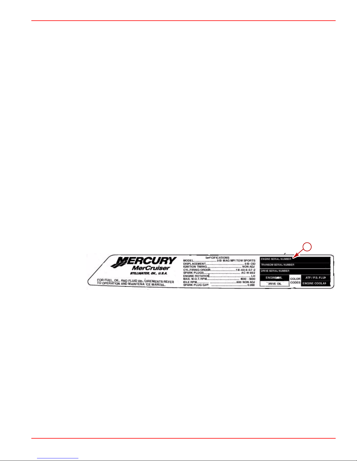
Affix engine serial number decal to specification / serial number decal in position shown.
a-Engine Serial Number Location
Engine Rotation
Engine rotation is described when observed from the rear of the engine (transmission end)
looking forward (water pump end). Engine rotation is indicated on engine specifications and
serial number decal.
a
77962
90-864198020 Page 5 of 77
Page 6
INSTALLATION MANUAL
Transmissions
Velvet Drive Transmissions
On the Velvet Drive 71C and 72C In-Line and 72C Remote V-Drive Transmissions the gear
ratio (in FORWARD gear) is marked on transmission identification plate. Transmission output shaft rotation and propeller rotation required (in FORWARD gear) are indicated on a decal on the transmission case. Transmission rotation is described when viewed from the rear
of transmission.
22556
In-Line Transmission Shown (Remote V-Drive Similar)
a-Transmission Identification Plate
b-Gear Ratio (In FORWARD Gear)
c-Output Flange Rotation Decal (In FORWARD Gear)
On the Velvet Drive 5000A and 5000V Transmissions the transmission identification plate
indicates gear ratio, serial number and model.
a
71778
Velvet Drive 5000A 8 Degree Down-Angle Transmission Shown (5000V V-Drive
Similar)
a-Transmission Identification Plate
Page 6 of 77 90-864198020
Page 7
ZF / Hurth Transmissions
On the ZF / Hurth 630A 8 Degree Down-Angle and 630V V-Drive Transmissions the
transmission identification plate indicates gear ratio, serial number and model.
Typical ZF / Hurth Down-Angle Transmission Shown (V-Drive Similar)
a-Transmission Identification Plate
INSTALLATION MANUAL
a
73587
90-864198020 Page 7 of 77
Page 8
INSTALLATION MANUAL
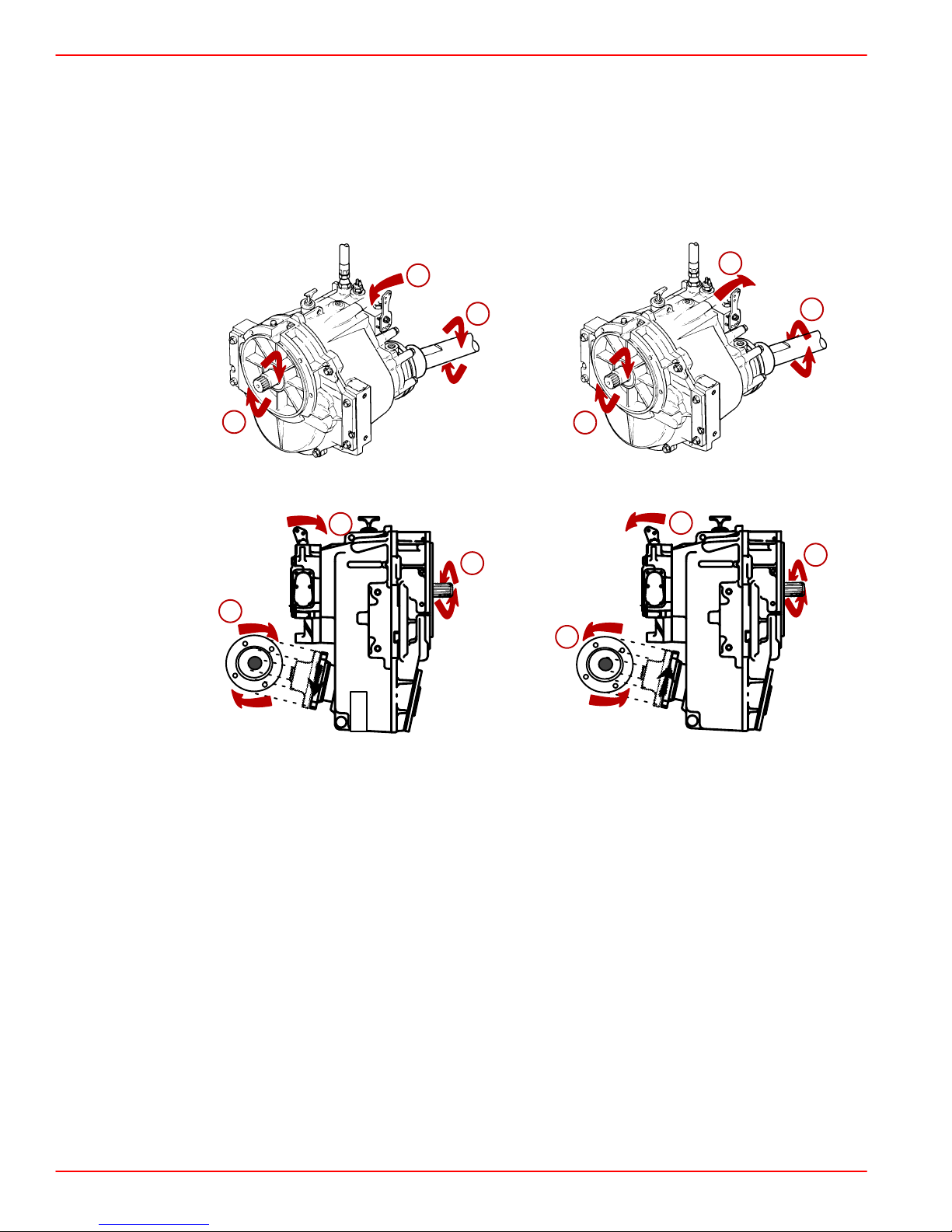
Propeller Rotation
Propeller rotation is not necessarily the same as engine rotation. Refer to the appropriate
following information and drawings for specific information.
These transmissions are full power reversing transmissions, allowing a standard (LH
rotation) engine to be used for both propeller rotations. Propeller rotation (output shaft
rotation) is determined by shift cable attachment at the remote control. Be sure to use
correct rotation propeller and shift cable hook up for direction desired.
a
c
b
Velvet Drive 5000A - 8 Degree Down-Angle Transmission
b
a
b
f
g
d
e
71888
d
b
Velvet Drive 5000V - V-Drive Transmissions
a-Direction of Shift Lever Engagement (Toward Flywheel)
b-Engine/Transmission Input Shaft Rotation Direction (LH)
c-Transmission Output/Propeller Shaft Rotation Direction (LH)
d-Direction of Shift Lever Engagement (Away From Flywheel)
e-Transmission Output/Propeller Shaft Rotation Direction (RH)
f-Transmission Output/Propeller Shaft Rotation Direction (LH as viewed at
propeller)
g-Transmission Output/Propeller Shaft Rotation Direction (RH as viewed at the
propeller)
74604
Page 8 of 77 90-864198020
Page 9
INSTALLATION MANUAL
a
d
b
c
e
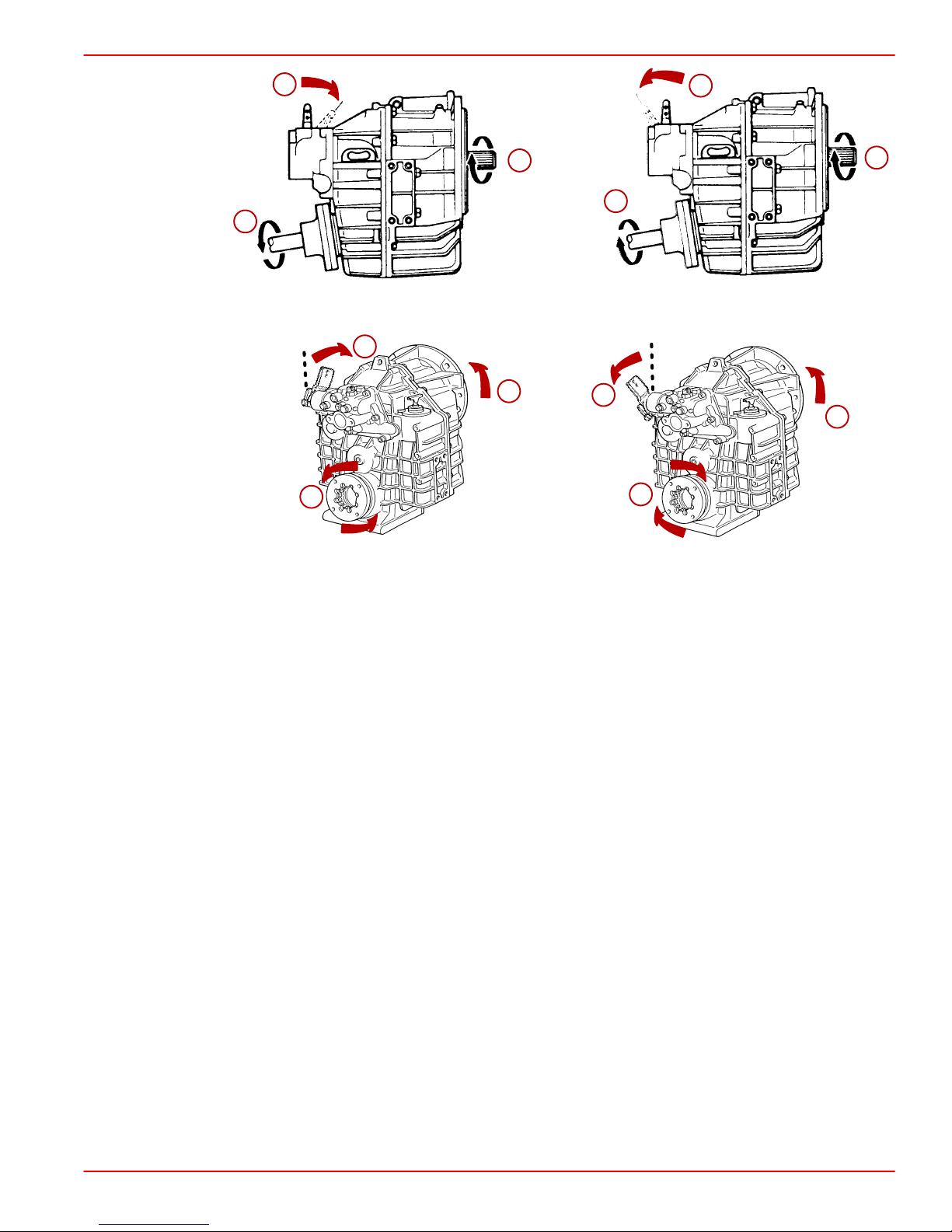
ZF / Hurth 630A or 800A - 8 Degree Down-Angle Transmissions
a
b
c
d
e
b
25506
b
72959
ZF / Hurth 630V - V-Drive Transmissions
a-Direction Of Shift Lever Engagement (Toward Flywheel)
b-Engine/Transmission Input Shaft Rotation Direction (LH)
c-Transmission Output/Propeller Shaft Rotation Direction (LH)
d-Direction Of Shift Lever Engagement (Away From Flywheel)
e-Transmission Output/Propeller Shaft Rotation Direction (RH)
90-864198020 Page 9 of 77
Page 10

INSTALLATION MANUAL
DUAL INSTALLATIONS
Best all-around performance usually is obtained by installing engines so that propellers turn
outboard (looking at the stern).
a
c
a-Outboard Propeller Rotation
b-RH Rotation
c-LH Rotation
b
VELVET DRIVE IN-LINE AND V-DRIVE TRANSMISSIONS (EXCEPT 5000 SERIES)
IMPORTANT: Velvet Drive In-Line and V-Drive Transmissions Only – Use of proper
rotation propeller (specified on transmission output flange rotation decal) is critical
since the transmission must be operated in FORWARD gear selector position only
to drive boat forward. If the wrong rotation propeller is installed and transmission is
operated in REVERSE to propel the boat forward, transmission failure WILL occur.
IMPORT ANT: On engines which are equipped with Velvet Drive In-line transmissions,
a LH propeller is required.
Boat Construction
Engine Bed
Difference Between Starboard and Port Engine Mount 22-1/2 in. (572 mm)
Mount Adjustment Up and Down (minimum) 1/4 in. (6mm)
22457
NOTE: Although the engine mounts allow some adjustment, ensure that the front and rear
mount locations in the vessel are in the same plane and parallel. This may be checked by
tying a string from the left front mount location to the right rear mount location and another
from right front to left rear. The strings should touch where they cross
Page 10 of 77 90-864198020
.
Page 11
Seawater Connections - General Information
NOTICE
Refer to manufacturer’s instructions for information on removal and installation of
other than Quicksilver Seawater Pickups.
IMPORT ANT: Seal the inside edges of any hole made through the hull with a suitable
sealant to prevent water absorption and deterioration.
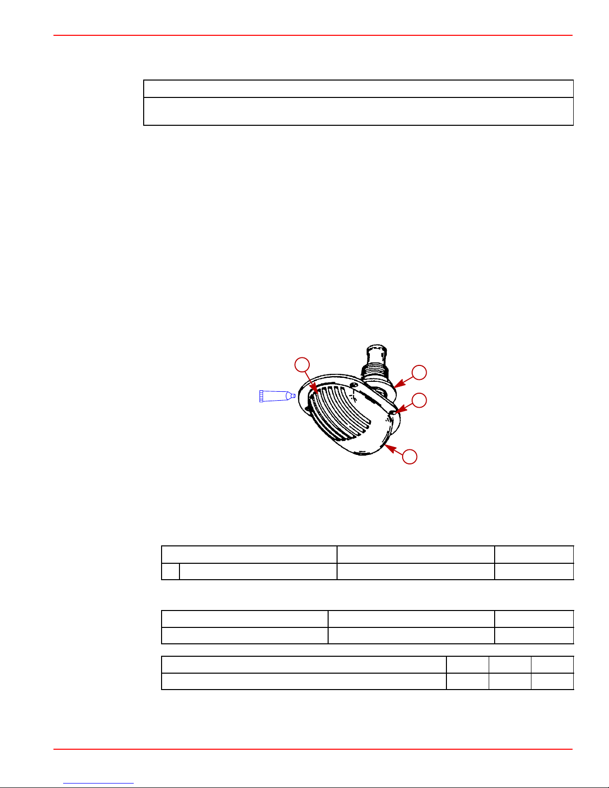
Seawater Pickup
THROUGH THE HULL MOUNTED
1. Seal inside edges of 1-3/4 in. (44 mm) hole in hull using a suitable sealer.
2. Apply marine caulking (sealer) to mounting surface on seawater pickup where hull
contact will occur when installed.
IMPORT ANT: Seawater inlet slots must face forward - parallel with the flow of water .
3. Ensure slots in seawater pickup are facing forward (toward bow of boat) and install
seawater pickup through hull.
4. Fasten pickup with four appropriate mounting screws (if so designed).
INSTALLATION MANUAL
5. Apply marine caulking as needed inside boat.
b
A
a-Seawater Pickup
b-Seawater Inlet Slots
c-Mounting Screw Holes (If Equipped)
d-Nut
Description
A Marine Caulking Mounting Surfaces Obtain Locally
6. Apply sealant to threads of nut and install on pickup on inside of boat and torque nut.
Where Used Part Number
d
c
a
72639
Description
Loctite 271 Seawater Inlet Nut 92-809820
Description Nm lb-in. lb-ft
Nut 42 35
NOTE: If pickup being installed does not have mounting screws on underside where
mounted to hull, be certain, after nut is torqued, that slots are still facing forward.
90-864198020 Page 11 of 77
Where Used Part Number
Page 12
INSTALLATION MANUAL
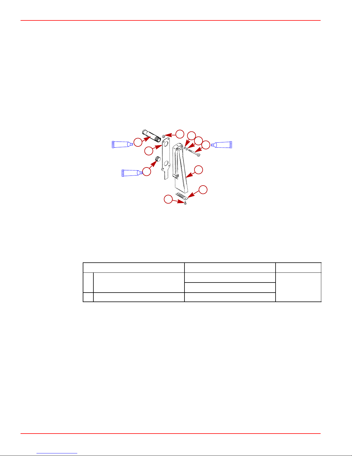
TRANSOM MOUNTED
1. Seal the inside edges of the 1-1/2 in. (38 mm) hole hose fitting.
2. Ensure that the hose fitting and plastic plug are in place and threads have been sealed
prior to tightening each securely.
NOTE: Use a sharp knife or wood chisel to remove excess plastic plug material so that plug
is flush with pickup casting.
3. Position one flat washer and one rubber O-ring on each 5/16 in. x 4 in. (102 mm) long,
round head screw. Coat each screw shaft with sealant.
4. Place new gasket on pickup housing and hold pickup in place on transom. Install four
round head screws (with washers and O-rings in place) into pickup mounting holes and
through drilled 21/64 in. (8 mm) holes in transom.
b
d
A
a
e
B
f
c
g
A
h
i
j
a-Hose Fitting
b-Nut (4)
c-Gasket
d-O-ring (4)
e-Washer (4)
Description
A Loctite 592 PST
B Silicone Sealant Or Equivalent Screw Shaft
Hose Fitting Threads
Plastic Plug Threads
72640
f-Screw (4)
g-Plastic Pug
h-Pickup
i-Screen
j-Screw (2)
Where Used Part Number
Obtain Locally
Page 12 of 77 90-864198020
Page 13

INSTALLATION MANUAL
NOTE: Some installations may have 7/32 in. (5 mm) holes drilled in transom using four 5/16
in. diameter stainless steel lag bolts in place of round head screws. In any case, flat washers
and O-rings are required as outlined.
a
b
72641
Water Pickup Installed on Transom
a-Diagonal Mount - Leading Edge Of Pickup 1/8 in. (3.2 mm) From Boat Bottom.
b-Vertical Mount - Corner Of Leading Edge Of Pickup 1/8 in. (3.2 mm) From Boat
Bottom
5. Secure water pickup from inside with locknuts and washers (unless using lag bolts).
6. Tighten fasteners securely.
90-864198020 Page 13 of 77
Page 14
INSTALLATION MANUAL
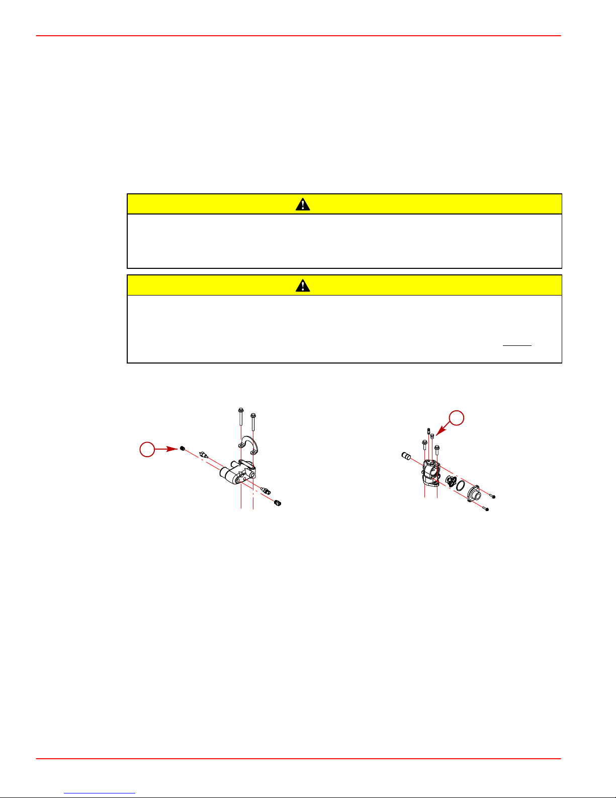
Preliminary Connections
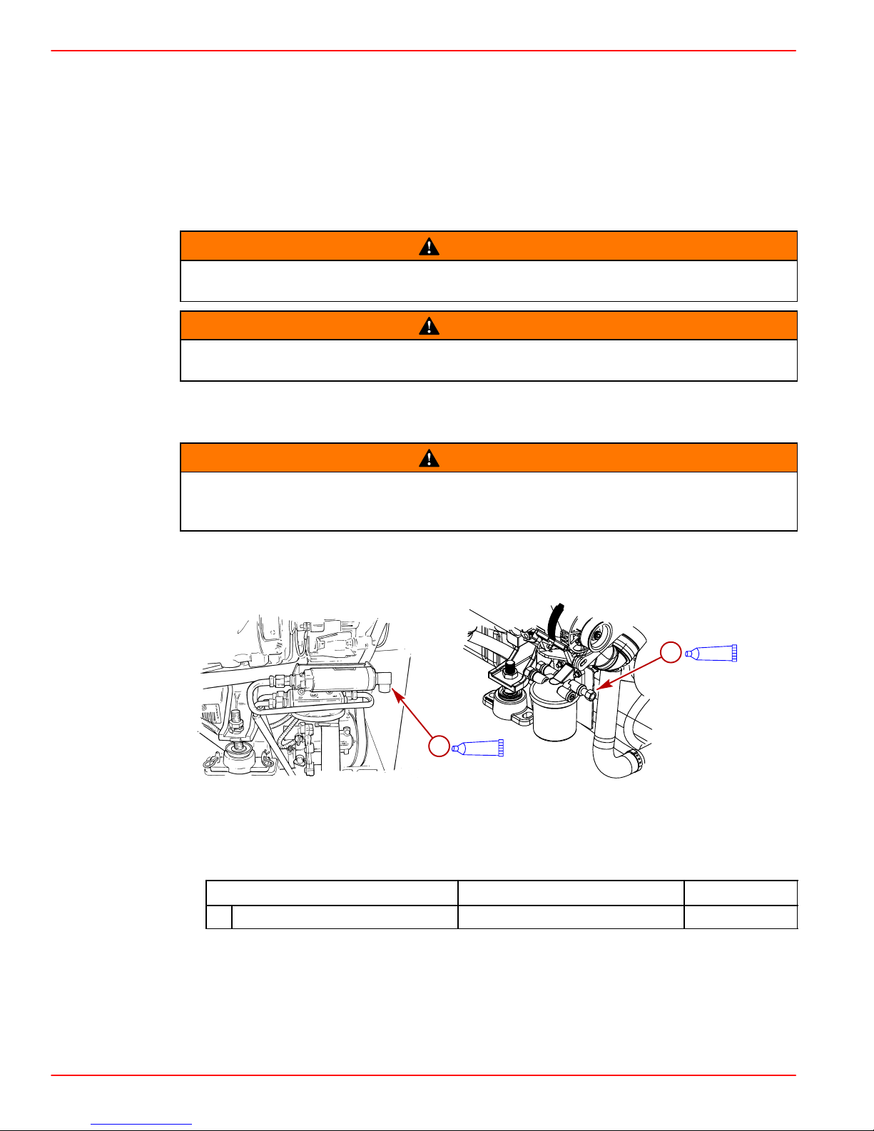
Fuel Inlet Fitting
IMPORTANT: The following information is provided to ensure proper installation of
brass fittings or plugs installed into fuel pump or fuel filter base:
• Use #592 Loctite Pipe Sealant with Teflon on threads of fuel inlet fittings or plugs.
DO NOT USE TEFLON TAPE.
Boating standards (NMMA, ABYC and others) and Coast Guard regulations must
be adhered to when installing fuel delivery system.
Avoid gasoline fire or explosion. Improper installation of brass fittings or plugs into
fuel pump or fuel filter base can crack casting and/or cause a fuel leak.
1. Remove plastic plug from fuel inlet hole.
2. Apply sealant to threads of fuel inlet fitting. DO NOT USE TEFLON TAPE.
WARNING
WARNING
WARNING
Overtightening the fuel inlet fitting can lead to fuel leaks, avoid severe personal
injury or death from a gasoline fire or explosion. DO NOT use a power tool (i.e.
impact wrench) to tighten the fuel inlet fitting.
3. Install fuel inlet fitting in fuel pump or filter base. To prevent cracking the casting or
causing fuel leaks, turn fuel inlet fitting in by hand until finger tight. Tighten the fitting an
additional 1-3/4 to 2-1/4 turns with wrench. DO NOT OVERTIGHTEN.
a
a
78276
Models With Boost Pump Models With Out Boost Pump
a-Fuel Inlet Fitting
A
A
77950
Description
A Loctite 592 Fuel Inlet Fitting Obtain Locally
Page 14 of 77 90-864198020
Where Used Part Number
Page 15
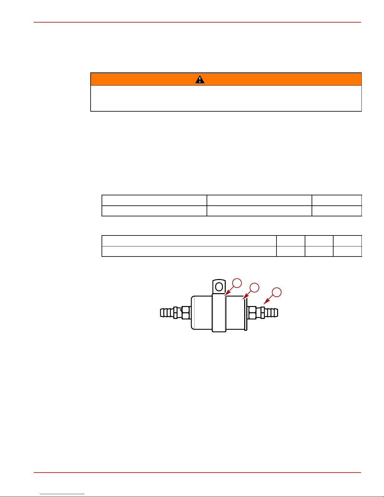
Inline Fuel Filter
INSTALLATION
IMPORTANT: If the engine is equipped with a boost pump, an inline filter must be
installed between the fuel tank and the boost pump.
Avoid injury or death and power package damage from an electrical shock, fire or
explosion. Always disconnect both battery cables from the battery before servicing
the power package.
1. Disconnect both battery cables from the battery.
2. Install boat fuel line from the tank to the engine.
3. With the engine installed, locate a section of the fuel line in a serviceable location,
4. Remove 76 mm (3 in.) of fuel line in mounting location.
5. Select appropriate size connector for the fuel line and install the connector on the filter.
6. Apply sealant to the male pipe threads on the connectors.
INSTALLATION MANUAL
WARNING
leaving enough room for filter, connections and bracket mounting.
Description
Where Used Part Number
Loctite 565 Male Threads Obtain locally
7. Torque connectors.
Description
Nm lb-in. lb-ft
Connectors 19-27 14-20
8. Insert filter into the mounting clip.
c
a
b
a-Inline Filter
b-Connectors
c-Mounting Clip
78289
90-864198020 Page 15 of 77
Page 16
INSTALLATION MANUAL
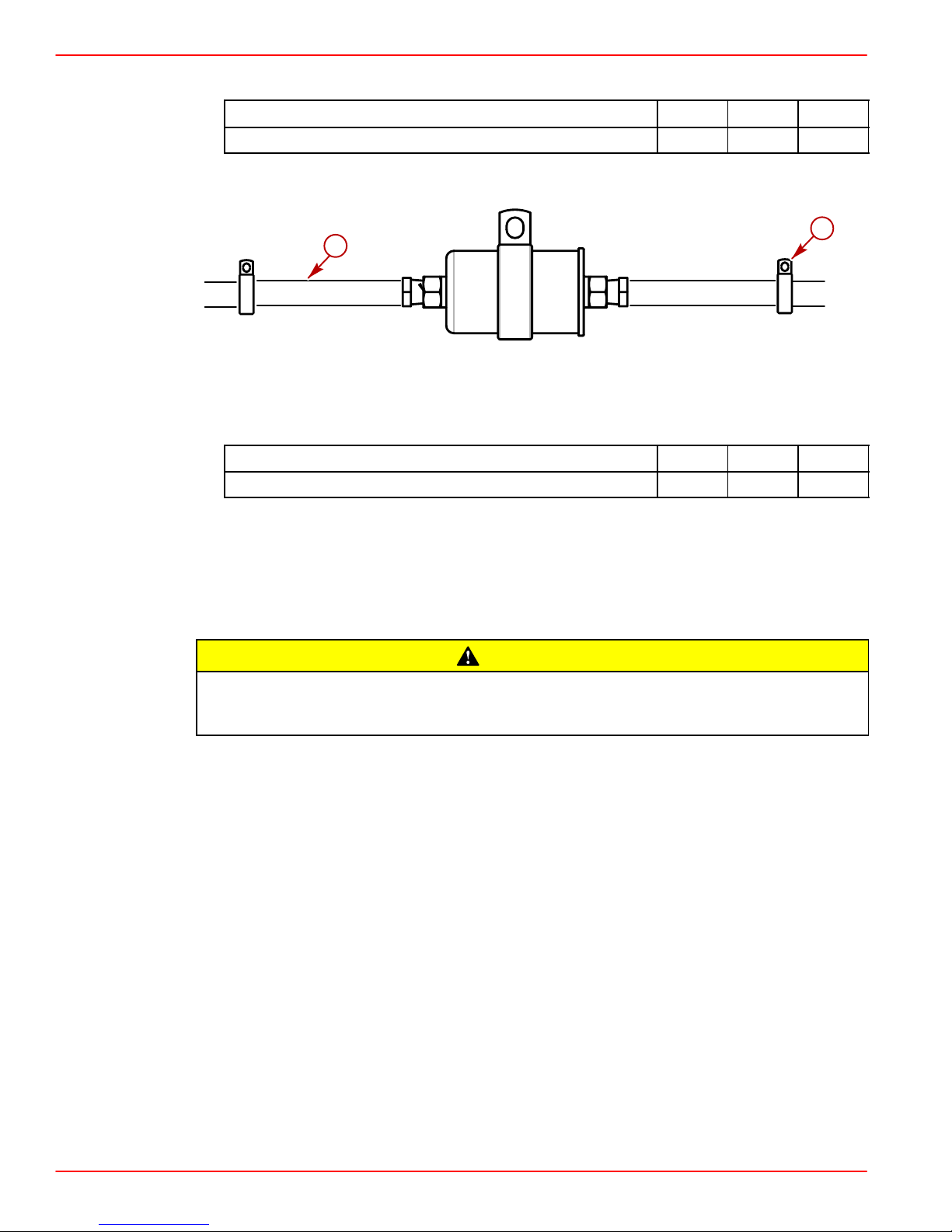
9. Install and torque screw and washer through the mounting clip into the stringer.
Description
Nm lb-in. lb-ft
Screw, Mounting Clip 12.2 9
10. Install and torque hose clamps over hose and insert barbs into hose.
a
b
78289
a-Fuel Line Stringer Clips
b-Fuel Line
Description
Hose Clamps 3.4-6.8 30-60
11. Inspect the fuel line stringer clips to ensure that the recommended length between clips
has not been exceeded. The maximum allowable length is 45.7 mm (18 in.).
Nm lb-in. lb-ft
12. Pressurize the fuel system and check for leaks. Relieve pressure and then check for
leaks again.
SPECIAL INFORMATION ABOUT ELECTRIC FUEL PUMPS
CAUTION
The electric fuel pump and factory installed water separating fuel filter have been
carefully designed to function properly together . Do not install additional fuel filters
and/or water separating fuel filters between fuel tank and engine.
The installation of additional filters may cause:
• Fuel Vapor Locking
• Difficult Warm-Starting
• Piston Detonation Due to Lean Fuel Mixture
• Poor Driveability
Page 16 of 77 90-864198020
Page 17
Coolant Recovery System Connections
1. Select a mounting location for coolant recovery bottle and mounting bracket that meets
all of the following:
• Within limits of clear plastic tubing.
• Level with or above the heat exchanger fill neck.
• Accessible for observing coolant level and filling.
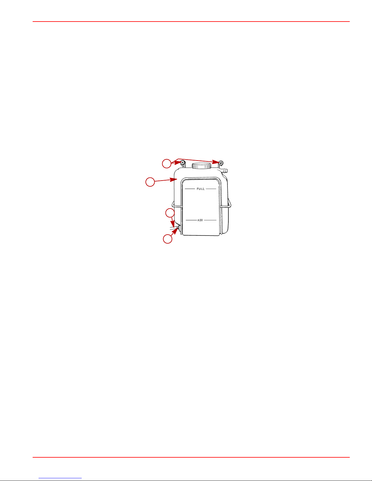
2. Mount coolant recovery bottle and mounting bracket in desired location, using two
3/4 in. (19 mm) long screws and flat washers.
3. Route plastic tubing to recovery bottle. Ensure that tubing is positioned away from any
moving parts. Cut plastic tubing as required and connect to bottom connection on recovery bottle and secure with tubing clamp provided.
4. Fasten plastic tubing to boat as necessary, with the 2 hose clips and 1/2 in. (13 mm) long
screws provided.
b
a
INSTALLATION MANUAL
c
d
a-Recovery Bottle And Mounting Bracket
b-Screws And Flat Washers
c-Plastic Tubing
d-Tubing Clamp
70547
90-864198020 Page 17 of 77
Page 18
INSTALLATION MANUAL
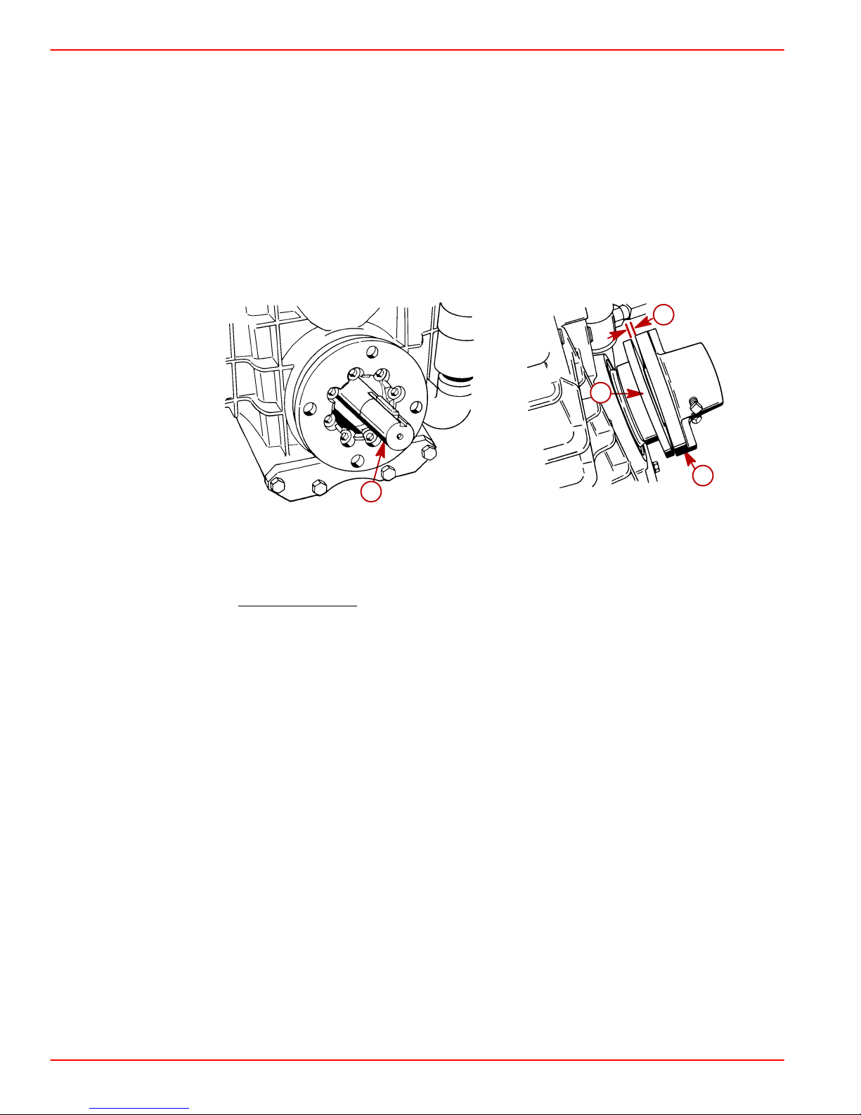
Engine Mount Pre-Adjustment
1. Remove hardware holding engine to shipping pallet. Attach a suitable sling to lifting eyes
on engine. Lift engine from pallet with an overhead hoist.
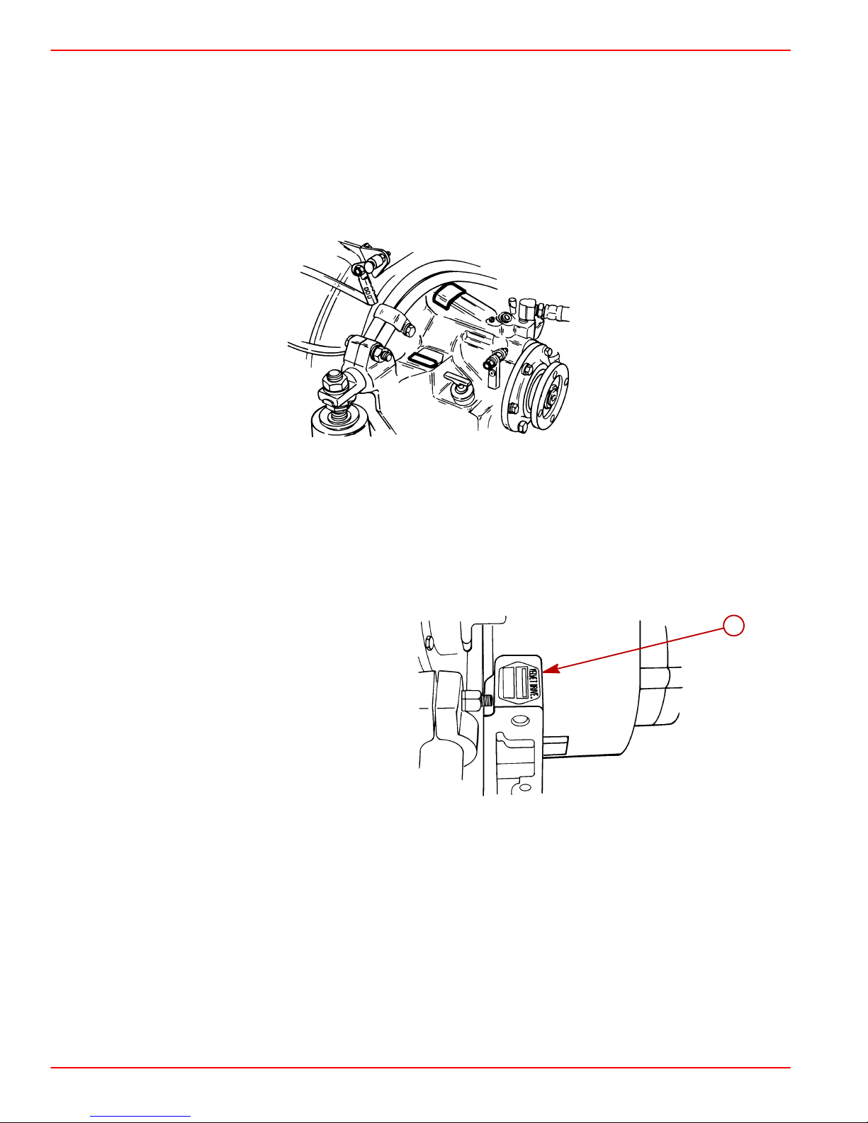
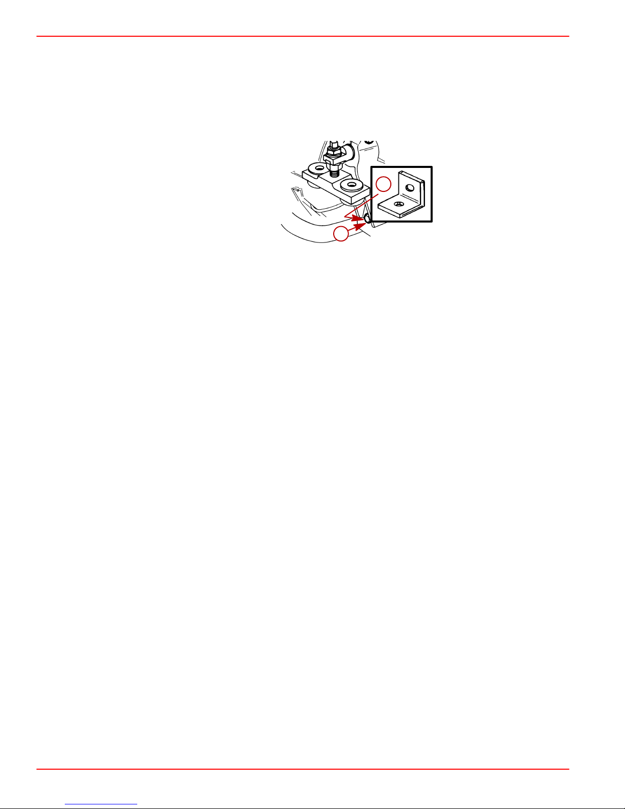
2. Remove L-shaped shipping bracket from both rear (transmission) mounts as shown.
Retorque mount bracket attaching screw to 47 lb-ft (64 Nm).
a
b
74623
Typical
a-L-shaped Bracket
b-Transmission Mount Bracket Attaching Screw
IMPORTANT: Engine mounts must be adjusted, as explained in Steps 3. and 4., to
center mount adjustment and establish a uniform height on all mounts.
3. Check all 4 engine mounts (2 front, 2 rear) to ensure that distance from bottom of mount
to bottom of trunnion is as shown. If not, loosen mount locking nut and turn adjusting nut
in direction required to obtain proper dimension, then retighten locking nut. Be sure to
leave mount positioned so that slot is forward.
4. Loosen clamping bolts and nuts on all 4 engine mount brackets to ensure the following:
• Large diameter of mount trunnion extended.
• Mount base slotted mounting hole forward, if so designed.
• Each mount base is downward. Tighten clamping bolts and nuts slightly to prevent mov-
ing in or out. Mounts must be free to pivot when installing engine.
Page 18 of 77 90-864198020
Page 19
Engine Preparation
1. Remove and read all tags attached to engine.
2. Remove all hardware that secures engine to shipping container.
3. Connect battery cables to engine. Be sure to observe the following:
a. Ensure that grounding stud and starter solenoid terminal are free of paint or any oth-
er material that could cause a poor electrical connection.
b. After battery cables are connected, apply a thin coat of sealant to the terminals.
INSTALLATION MANUAL
Description
Liquid Neoprene Battery Terminals 92-25711-2
c. Be sure to slide rubber boot over positive (+) terminal after making connection.
IMPORTANT: There is a fuse located at the starter solenoid. DO NOT remove this fuse.
The positive battery cable must be connected to the same stud as the fuse.
Where Used Part Number
c
a
b
77001
a-Positive (+) Battery Cable
b-Starter Solenoid
c-90 Amp Fuse - DO
NOT Remove
4. Drape battery cables over top of engine to prevent interference during installation.
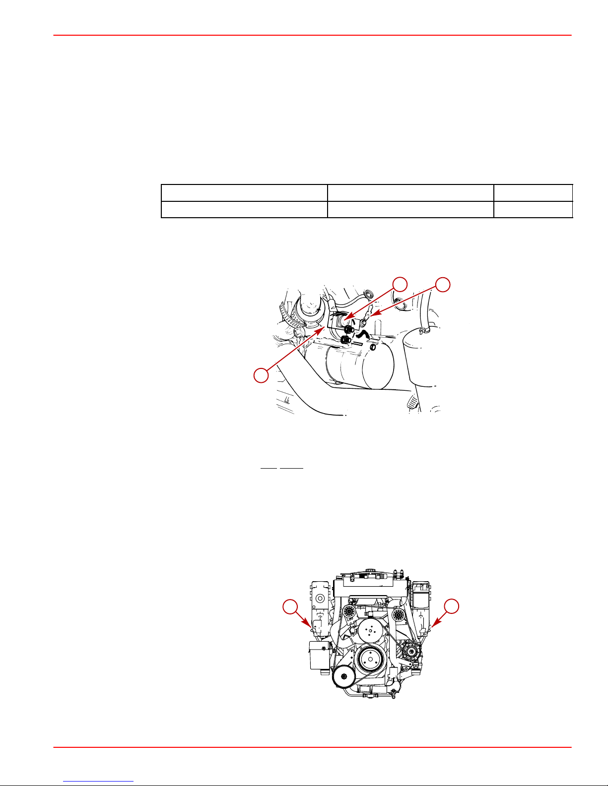
Engine Oil Dipstick Relocation (If Equipped)
Engine crankcase oil dipstick can be located on either starboard or port side of engine to
suit installation requirements. To move dipstick, remove dipstick from current location and
install in opposite side. Place rubber cap over the open dipstick tube.
a-Dipstick
90-864198020 Page 19 of 77
a
a
77954
Page 20
INSTALLATION MANUAL
Engine Installation and Initial Engine Alignment
Models With 8 Degree Down Angle Transmissions - Velvet Drive or ZF / Hurth
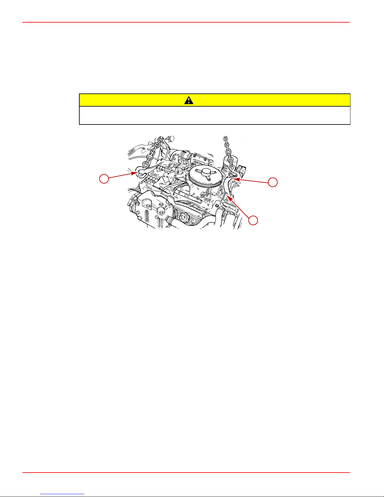
1. Remove the engine cover.
2. Attach a suitable sling to lifting eyes on engine and adjust so that engine is level when
suspended.
CAUTION
Center lifting eye on top of thermostat housing is used for engine alignment only.
Do not use to lift entire engine.
b
c
a-Front Lifting Eye
b-Rear Lifting Eye
c-Center Lifting Eye
3. Lift engine into position in boat using an overhead hoist.
a
77912
Page 20 of 77 90-864198020
Page 21
INSTALLATION MANUAL
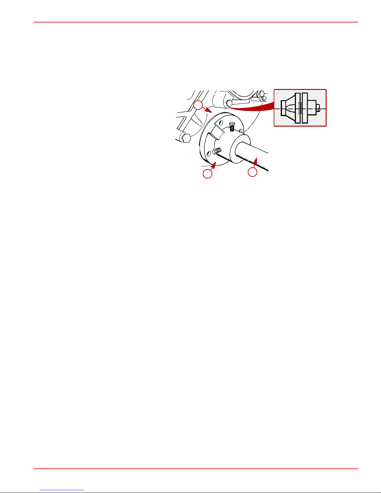
4. Position engine on engine bed so that transmission output flange and propeller shaft
coupler are visibly aligned (no gap can be seen between coupling faces when butted
together). Adjust engine height if necessary to obtain proper alignment. DO NOT use
mount adjustments to adjust engine position at this time.
IMPORTANT: Engine bed must position engine so that a minimum of 1/4 in. (6 mm)
up and down adjustment still exists on all 4 mounts after performing initial alignment.
This is necessary to allow for final engine alignment.
c
b
a
74546
a-Propeller Shaft
b-Propeller Shaft Coupler
c-Transmission Output Flange
5. Ensure quick drain oil fitting is more than 1/2 in. (13 mm) above the boat bottom.
IMPORT ANT: If quick drain oil fitting is within 1/2 in. (13 mm) of boat bottom, remove
fitting and install drain plug from parts bag directly into oil pan.
6. Ensure that all 4 mounts are still positioned properly, then fasten mounts t o engine bed
with 3/8 in. (10 mm) diameter lag bolts (of sufficient length) and flat washers. Tighten
lag bolts securely.
7. Disconnect overhead hoist and remove sling.
90-864198020 Page 21 of 77
Page 22
INSTALLATION MANUAL
Models with V-Drive Transmissions
1. Lift engine into position in boat using an overhead hoist.
2. Install quick drain oil hose plug in oil drain hose.
3. Position engine so that enough propeller shaft protrudes through transmission and output flange for propeller shaft coupler to be attached. Then install coupler and position
engine (no gap can be seen between coupling faces when butted together). Adjust en-
gine height if necessary to obtain proper alignment. DO NOT use mount adjustments
to adjust engine position at this time.
IMPORTANT: Engine bed must position engine so that a minimum of 1/4 in. (6 mm)
up and down adjustment still exists on all 4 mounts after performing final alignment.
This is necessary to allow for final engine alignment.
d
c
a
50608 50608
b
ZF / Hurth 630V (Others Similar)
a-Propeller Shaft
b-Propeller Shaft Coupler
c-Transmission Output Flange
d-No Gap Allowed
4. Ensure quick drain oil fitting is more than 1/2 in. (13 mm) above the boat bottom.
IMPORT ANT: If quick drain oil fitting is within 1/2 in. (13 mm) of boat bottom, remove
fitting and install drain plug from parts bag directly into oil pan.
5. Ensure that all 4 mounts are still positioned properly. Fasten mounts to engine bed with
3/8 in. (10 mm) diameter lag bolts (of sufficient length) and flat washers. Tighten lag bolts
securely.
6. Disconnect overhead hoist and remove sling.
Page 22 of 77 90-864198020
Page 23
All Models
INSTALLATION MANUAL
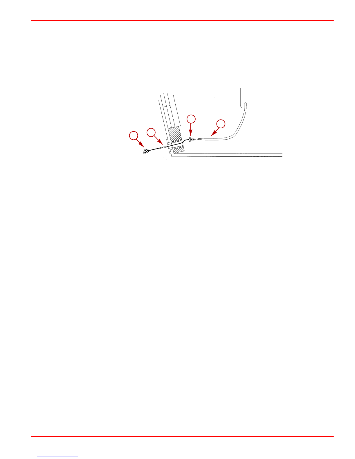
1. Push end of oil drain hose out of boat hull through flange.
2. Pull oil drain hose out until it is 6 in. (152 mm) from the propeller.
3. Move alignment clip on the oil drain hose and squeeze to position it on the hose just in-
side of the boat hull against the flange.
4. Connect bilge drain plug to oil drain hose plug using clip.
b
d
c
a
78002
a-Oil Drain Hose
b-Alignment Clip
c-Clip
d-Bilge Drain Plug
IMPORT ANT: If Quick Drain Oil Fitting is within 1/2 in. (13 mm) of boat bottom, remove
fitting and install drain plug from parts bag directly into oil pan.
5. Push oil drain hose through flange into boat hull.
6. Install bilge drain plug in hull.
90-864198020 Page 23 of 77
Page 24
INSTALLATION MANUAL
Hot Water Heater Installation
IMPORTANT: When connecting a cabin heater or hot water heater:
• Supply hose (from engine to heater) and return hose (from heater to engine)
MUST NOT EXCEED 5/8 in. (16 mm) I.D.
• Make heater connections ONLY at locations shown.
• Refer to manufacturers’ instructions for complete installation information and
procedures.
• Do not reposition engine temperature switch.
Avoid a performance loss and/or possible engine damage. Engine coolant must
flow continuously from the engine intake manifold to the engine water circulating
pump. NEVER close-off or block the coolant flow to or from a heater. All heater
installations must be plumbed in series with the supply and return connections.
Avoid engine overheating which could result in engine damage. On models
equipped with Closed Cooling, an air pocket may form in the closed cooling system
if some coolant is lost from the system and the cabin heater or hot water is mounted
higher than the fill cap on the heat exchanger. Heater must be mounted lower
the fill cap of the heat exchanger on models so equipped.
CAUTION
CAUTION
than
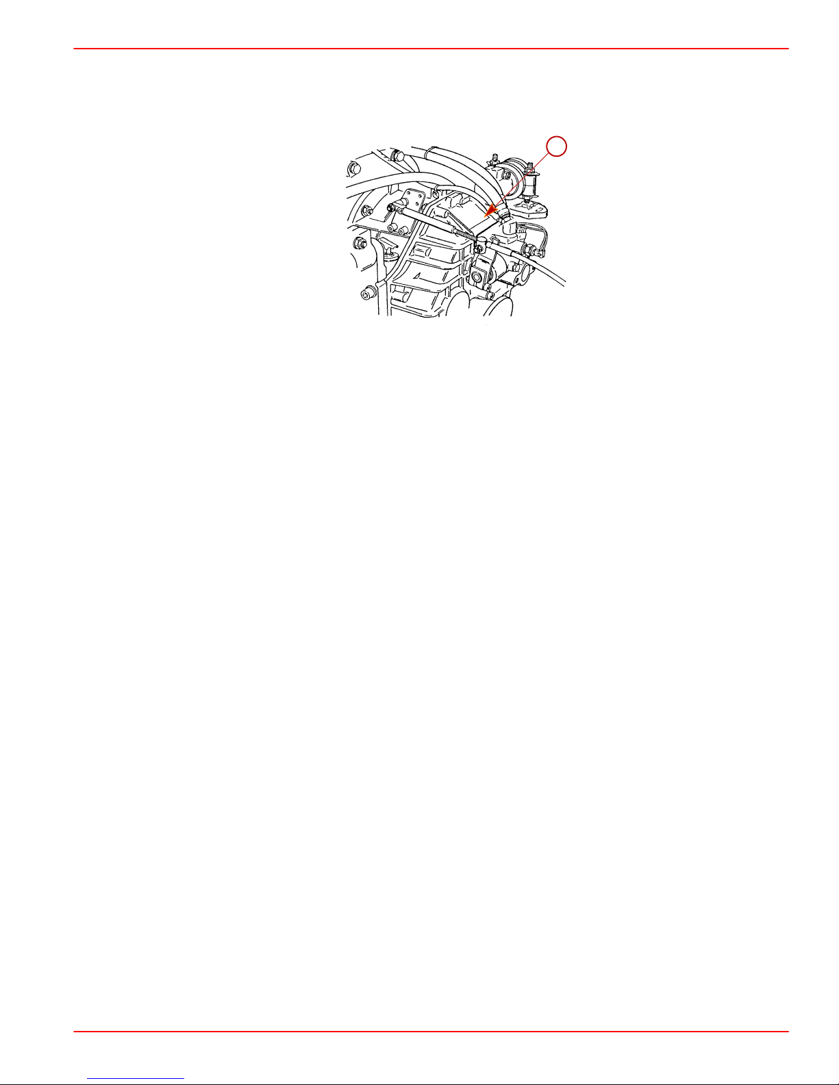
SUPPLY HOSE CONNECTION
NOTE: Some models may be equipped with additional fittings.
a
Seawater Cooled Models Closed Cooled Models
77816
a
77815
Page 24 of 77 90-864198020
Page 25

All Models
a-Location for Hot Water Supply
RETURN HOSE CONNECTION
INSTALLATION MANUAL
77933
a
a
a-Location For Hot Water Return
77954
90-864198020 Page 25 of 77
Page 26

INSTALLATION MANUAL
Exhaust System
It is the responsibility of the boat manufacturer or installing dealer to properly locate the engine and install the exhaust system. Improper installation may allow water to enter the exhaust manifolds and combustion chambers and severely damage
the engine. Damaged caused by the water in the engine will not be covered by Mercury MerCruiser Warranty, unless this damage is the result of defective parts.
MEASURING PROCEDURE
1. Fill all fuel, water, gray water and heater tanks to maximum capacity.
NOTE: Weight can be added in these locations to simulate full loaded condition.
2. Add maximum allowable cargo weight to boat in areas where it will be stowed, including
refrigerator and lockers.
3. Add 190 lb (86 kg) of weight in all locations where each passenger will sit during normal
operation.
4. Measure exhaust elbow height. Refer to Measurement Methods. Also, measure
exhaust system slope on applications with through the hull or through the transom
exhaust.
CAUTION
a
b
Using A Universal Protractor (Inclinometer) To Measure Slope
a-Protractor
b-Exhaust Hose Or Tube
77981
Page 26 of 77 90-864198020
Page 27

INSTALLATION MANUAL
5. Move load weight to bow to simulate greatest bow-down attitude the boat will encounter
in normal operation.
6. Recheck exhaust system slope.
7. Move load weight and cargo weight to stern of boat to stimulate greatest stern-down
attitude the boat will encounter such as when loading.
IMPORTANT: Be sure to consider swim platform loading and personal watercraft.
8. Recheck exhaust system measurements.
Minimum Exhaust Elbow Height from Top of Elbow to Waterline
Model Measurement
All V6 and V8 13 in. (330 mm)
a
b
c
d
a-Top Of Transom
b-Highest Point On Exhaust Elbow
c-Measurement
d-Waterline
Minimum Continuous Downward Slope (Exhaust Hoses, Collector, Etc.)
Model Measurement (degrees)
All Sterndrive 6
77956
90-864198020 Page 27 of 77
Page 28

INSTALLATION MANUAL
9. If measurements are less than specified, exhaust elbow risers must be installed to
achieve proper dimension.
11
9
6
9
14
7
4
12
5
10
3
13
2
1
8
No Riser 3 Inch Riser 6 Inch Riser
1-Exhaust Manifold
2-Restrictor Gasket
3-Exhaust Elbow
4-3 Inch Riser
5-6 Inch Riser
6-Open Gasket
7-Plug
8-Bolt, Manifold-To-Cylinder Head
9-Bolt, Exhaust Elbow-To-Exhaust Manifold
10 - Stud
11 - Nut And Washer, Exhaust Elbow-To-3 Inch Riser
12 - Bolt, 6 Inch Riser-To-Exhaust Manifold
13 - Hose Fitting
14 - Pipe Plug
78489
Page 28 of 77 90-864198020
Page 29

Measurement Methods
STRAIGHT EDGE METHOD
1. Place a straight edge across boat.
2. With the straight edge above the engine and parallel to the water , measure the distances
between the straight edge and the top of the exhaust elbow.
3. With the straight edge above the engine and parallel to the water measure the distance
between the straight edge and the outside waterline.
4. The difference between these two measurements is the exhaust elbow height above the
water line. Refer to Measuring Procedure and compare measurement to Mercury
MerCruiser’s specifications.
c
INSTALLATION MANUAL
b
d
a
a-Waterline
b-Top Of Exhaust Elbow
c-Straight Edge
d-Measurement Between Straight Edge And Top Of Exhaust Elbow
e-Measurement Between Straight Edge And Water Line
e
76859
72700
90-864198020 Page 29 of 77
Page 30

INSTALLATION MANUAL
CLEAR HOSE METHOD
1. Obtain a 5/16 - 3/8 in. (8-10 mm) I.D. hose approximately 15 ft (4.5 m) long. Put a metal
fitting or a weight on one end of the hose to keep that end of the hose below the water
line.
2. Put the weighted end of the hose over the port or starboard side of the boat, keeping
it in line with the engine’s exhaust elbow.
3. Route the remainder of the hose toward the engine’s exhaust manifold and elbow.
Ensure that this open end section of the hose is as vertical as possible from the boat’s
bilge to the top of the exhaust elbow
4. Coil excess hose in bilge of boat, keeping it below the water line.
5. Lower open end of hose and siphon water until it starts to come out of the hose. Put a
finger over the hose and lift open end until it is at the top of the exhaust elbow.
6. Slowly take finger off end of hose to let the water level stabilize. The water will seek the
level of the water outside the boat. Keep hose close to exhaust elbow and as vertical
as possible.
7. The measurement between water in hose and top of exhaust elbow is the exhaust elbow
height. Ensure that boat is level.
c
b
a
a-Waterline
b-Top Of Exhaust Elbow
c-Clear Plastic Hose
d-Weight
e-Measurement - Waterline To Top Of Exhaust Elbow
Minimum Exhaust Outlet Hose Size
Model Single Outlet Dual Outlet
Inboard
350 MAG MPI /
350 MAG MPI Horizon
MX 6.2L MPI /
MX 6.2 MPI Horizon
Tow Sports
4 in. (102 mm) 3 in. (76 mm)
e
76859
a
d
72700
350 MAG MPI 3 1/2 (88.9 mm) Not Applicable
Page 30 of 77 90-864198020
Page 31

INSTALLATION MANUAL
NOTE: A kit is available to reduce from the 4 in. (102 mm) to 3 in. (76 mm). Refer to the
Mercury Precision Parts / Quicksilver Accessories Guide, for kit part number.
d
c
e
Typical Continuously Sloping Exhaust Line
a-Exhaust Elbow
b-Exhaust Hose Or Pipe
c-Muffler (If Equipped)
d-Exhaust Outlet Internal Shutter
e-Exhaust Flapper Valve
f-Waterline
b
b
a
f
a
g
71774
d
c
e
Typical Waterlift Muffler Exhaust System
a-Vent Line [1/4 in. (6 mm)]
b-Transom
c-Water Line
d-Exhaust Hose
e-Drain Fitting
f-Water Lift Muffler
g-Exhaust Elbow
f
71775
CAUTION
Avoid severe engine damage. A 1/4 in. (6 mm) vent hose must be run from the highest point in the seawater system to the exhaust pipe after the water lift muffler to
break the vacuum and prevent water from back-filling the engine.
90-864198020 Page 31 of 77
Page 32

INSTALLATION MANUAL
Exhaust System Hose / Tube Connections
Avoid exhaust hose failure. Discharge water from exhaust elbow must flow around
entire inside diameter of hose to avoid causing hot spots which could eventually
result in burned-through exhaust hoses. Exhaust hoses and/or tubes must be correctly connected to exhaust elbows so that they do not restrict the flow of discharge
water from exhaust elbow.
Correct Connection Incorrect Connection
IMPORTANT: Exhaust hoses/tubes should be secured at each connection with at
least 2 hose clamps.
1. Tighten all exhaust hose and/or exhaust tube clamps securely.
CAUTION
71653
a
a-Hose Clamps
IMPORTANT: S-pipes must be routed under the transmission mounts.
a
b
Tow Sports Models
a-S-pipe
b-Transmission Mount
73961
74832
Page 32 of 77 90-864198020
Page 33

Electrical Connections
Avoid damage to the EFI electrical system components: Refer to the following precautions when working on or around the EFI electrical harness, or when adding other electrical accessories:
• DO NOT tap accessories into engine harness.
• DO NOT puncture wires for testing (Probing).
• DO NOT reverse battery leads.
• DO NOT splice wires into harness.
• DO NOT attempt diagnostics without proper, approved Service Tools.
IMPORTANT: When routing all wire harnesses and hoses, be sure they are routed and
secured to avoid coming in contact with hot spots on engine and to avoid contact
with moving parts.
Instrumentation Connections
We recommend the use of Quicksilver Instrumentation and Wiring Harnesses. On dual station applications, oil pressure and water temperature senders (on engine) must be changed.
Refer to Mercury Precision Parts / Quicksilver Accessories Guide for selection.
INSTALLATION MANUAL
CAUTION
The 4 basic gauges that must be used with the engine are:
• Tachometer
• Oil Pressure
• Water Temperature
• Voltmeter
IMPORT ANT: Connect fused accessory panel (40-amp current draw maximum) must
be connected as shown in the wiring diagrams.
1. Route instrumentation wiring harness back to engine, making sure that harness does
not rub or get pinched. If an extension harness is required, be sure to secure connection
properly.
2. Fasten harnesses to boat at least every 18 in. (460 mm), using appropriate fasteners.
3. Place hose clamp over instrumentation wiring harness.
90-864198020 Page 33 of 77
Page 34

INSTALLATION MANUAL
4. Connect the instrumentation wiring harness to engine harness plug at location shown.
a-Engine Harness Plug
5. Tighten hose clamp to secure wiring harness to engine harness plug.
Audio Warning System Connections
a
78030
WARNING
Alarm is not external ignition-proof, therefore, DO NOT mount alarm in engine or
fuel tank compartments.
1. Select a location for audio warning alarm which meets all of the following:
• alarm can be easily heard, yet is out of sight
• alarm can be easily accessed for installation and maintenance
• alarm will remain dry
• alarm is within length limits of the 18 in. purple alarm wire that connects to the “I” terminal
or 12 volt source on switched side of ignition switch.
NOTE: The terminal to which wire is attached must have no voltage when ignition switch
is in the OFF position.
2. Place alarm in desired location and secure to wire bundle with tie-strap provided.
3. Connect PURPLE wire from alarm to any PURPLE wire terminal on instrument gauge
or ignition switch. Tighten connection securely.
4. Connect TAN/BLUE wire from alarm to TAN/ BLUE wire from instrument harness.
5. Place the small (transparent) decals on the bottom of the water temperature and the oil
pressure gauges.
Page 34 of 77 90-864198020
Page 35

INSTALLATION MANUAL
6. Place the large decal on the instrument panel or other appropriate location in easily
viewed by the operator.
ALARM INDICATES LOW
OIL OR OVERHEATING
a
APPLY THE PROPER DECAL TO THE DASHBOARD
OR OTHER APPROPRIATE LOCATION:
AUDIO WARNING HORN WILL SOUND WHEN:
1. ENGINE OIL PRESSURE IS TOO LOW,
2. ENGINE WATER TEMP. IS TOO HOT, OR
3. TRANSMISSION TEMPERATURE IS TOO HOT.
TO TEST THE AUDIO WARNING HORN:
TURN KEY TO ON POSITION (ENGINE OFF)
a-Small Decal (Transparent)
b-Larger Decal
7. Test audio warning system during Predelivery Preparation section.
Fluid Connections
Coolant Recovery Bottle
Avoid engine overheating and subsequent damage to engine. The coolant recovery
system will not operate properly without proper sealing. Plastic tubing MUST seal
completely at connections.
1. Connect plastic tubing to bayonet fitting on heat exchanger. Secure with tubing clamp
provided.
b
75434
CAUTION
a-Plastic Tubing
b-Tubing Clamp
2. Remove cap from coolant recovery reservoir and fill to FULL mark with coolant solution.
3. Reinstall cap.
90-864198020 Page 35 of 77
b
a
70548
Page 36

INSTALLATION MANUAL
Final Engine Alignment
IMPORTANT: Engine alignment MUST BE RECHECKED with boat in the water, fuel
tanks filled and with a normal load on board.
Engine must be aligned so that transmission and propeller shaft coupling centerlines are
aligned and coupling faces are parallel within .003 in. (0.07 mm). This applies to installations
with solid couplings as well as flexible couplings.
1. Check mating faces on transmission output flange and propeller shaft coupler to ensure
that they are clean and flat.
2. Center propeller shaft in shaft log as follows:
a. Push down and then lift shaft as far as it will move. Then place shaft in the middle
of the movement.
b. Move shaft to port and then to starboard as far as shaft will move. Then place shaft
in the middle of the movement.
c. With shaft in the center of shaft log as determined by above procedures, align engine
to shaft.
a
d
b
c
Typical Down Angle (V-Drive Similar)
a-Up
b-Down
c-Port
d-Starboard
3. Check that coupling centerlines align by butting propeller shaft coupler against transmission output flange. Shoulder on propeller shaft coupler face should engage recess
on transmission output flange face with no resistance.
72595
72597
Incorrect Correct
Page 36 of 77 90-864198020
Page 37

INSTALLATION MANUAL
NOTE: Some propeller shaft couplers may not have a shoulder on mating face. On these
installations, use a straight edge to check centerline alignment.
c
a
b
d
74483
a-Transmission Output Flange
b-Propeller Shaft Coupler
c-Propeller Shaft
d-Straight Edge
4. Check for angular misalignment by hand holding coupling faces tightly together and
checking for a gap between coupling faces with a .003 in. (0.07 mm) feeler gauge. Check
the gap at 90 degree intervals.
a
b
c
75534
Velvet Drive
b
c
a
ZF / Hurth
a-Propeller Shaft Coupler
b-Feeler Gauge
c-Transmission Output Flange
50609
a
c
b
50608
90-864198020 Page 37 of 77
Page 38

INSTALLATION MANUAL
5. If coupling centerlines are not aligned or if coupling faces are more than .003 in.
(0.07 mm) out of parallel, adjust engine mounts.
a. TO ADJUST ENGINE UP OR DOWN: Loosen locking nut on mounts requiring
adjustment and turn adjusting nuts in desired direction to raise or lower.
IMPORTANT: Both front mounts (or rear mounts) adjusting nuts must be turned
equally to keep engine level from side to side.
NOTE: Some rear mounts have one (1) clamping screw and nut on each side.
b. TO MOVE ENGINE TO THE LEFT OR RIGHT: Loosen clamping bolts and nuts on
all 4 mount brackets and move engine to the left or right as necessary to obtain proper alignment. A small amount of adjustment can be obtained with slot on front end
of some mounts. Loosen lag bolts (which fasten mounts to engine bed) and move
engine, as required. Retighten lag bolts securely.
IMPORTANT: Large diameter of mount trunnion MUST NOT extend over 1-3/4 in.
(45 mm) from mount brackets on any of the mounts.
6. After engine has been properly aligned, secure engine mounts.
7. Torque clamping bolts and nuts on all 4 mount brackets.
Description lb-ft lb-in. Nm
Clamping Bolts And Nuts
50 68
8. Tighten locknut on all four mounts.
9. Bend one of the tabs on the tab washer down onto the flat of the adjusting nut.
IMPORTANT: All coupler bolts must be SAE Grade 8 (Metric Grade 10.9) or better, with
a shoulder (grip length) sufficient to pass through the mating face plane of the
couplers.
Page 38 of 77 90-864198020
Page 39

INSTALLATION MANUAL
10. Secure coupling together with bolts, lockwashers and nuts. Torque fasteners.
a
b
75535
a-Bolts
b-Transmission Coupler
Description lb-ft lb-in. Nm
Coupling Bolts And Nuts
a. If propeller shaft coupler has set screws, remove set screws and mark dimple loca-
tions using a transfer punch.
50 68
b. T o drill dimples, remove propeller shaft coupler and drill shallow dimples at locations
marked with punch.
c. Reinstall propeller shaft coupler and torque bolts. Install set screws and tighten se-
curely. Safety wire set screws to ensure they do not loosen.
b
c
d
e
a
50608
a-Propeller Shaft Coupler
b-Bolts
c-Set Screws
d-Safety Wire
e-Transmission Output Flange
Coupling Bolts And Nuts
90-864198020 Page 39 of 77
Description lb-ft lb-in. Nm
50 68
Page 40

INSTALLATION MANUAL
Throttle Cable Installation and Adjustment
IMPORT ANT: When installing throttle cable, be sure that cables are routed in such a
way as to avoid sharp bends and/or contact with moving parts. DO NOT fasten any
items to throttle cable.
1. Place remote throttle lever in idle position and attach cable to throttle body, following
cable manufacturer’s instructions.
2. Install cable end guide on throttle lever , then push cable barrel end lightly toward throttle
lever end. (This will place a slight preload on shift cable to avoid slack in cable when
moving remote control lever.) Adjust barrel on throttle cable to align with hole in anchor
plate. Ensure hole in barrel positions cable as shown. Tighten locknut until it contacts
washer, and then loosen 1/2 turn.
a
b
c
a-Cable End
b-Cable Barrel
c-Locknut and Flat Washer
Shift Cable Installation And Adjustment
IMPORTANT: When installing shift cables, be sure that cables are routed in such a
way as to avoid contact with moving parts and/or sharp bends All bends must make
greater than an 8 in. (203 mm) radius. DO NOT fasten any items to shift cables.
Shift cable must be hooked up to remote control before starting installation and adjustment
procedures. Refer to Transmission - Propeller Rotation, as previously outlined in the front
of this manual, for transmission shift lever direction of movement versus propeller shaft
output direction of rotation.
Damage caused to transmission as a result of improper shift lever positioning will not be
covered by warranty.
To ensure proper shift and throttle operation, we recommend the use of a Quicksilver remote
control and cables. Refer to Mercury Precision Parts / Quicksilver Accessories Guide.
Shift Cable Travel
78033
2-3/4 in. (70 mm)
Page 40 of 77 90-864198020
Page 41

Velvet Drive Transmissions
IN-LINE AND REMOTE V-DRIVE
IMPORT ANT: V elvet Drive Transmission Warranty is jeopardized if the shift lever poppet ball or spring is permanently removed, if the shift lever is repositioned or changed
in any manner or if remote control and cable do not position shift lever correctly.
INSTALLATION MANUAL
FNR––
a
d
e
b
F
R
c
22457
a-Transmission Shift Lever
b-Shift Lever MUST BE Over This Letter In FORWARD
c-Shift Lever MUST BE Over This Letter In REVERSE
d-Poppet Ball MUST BE Centered In Detent Hole For Each F-N-R Position
(FORWARD Gear Shown)
e-Install Shift Lever Stud in This Hole, If Necessary, To Center Poppet Ball in
FORWARD And REVERSE Detent Holes
1. Verify shift cable stud is in appropriate stud hole as indicated. Tighten elastic stop nut
securely.
a
50947
a-Shift Cable Anchor Stud Hole
90-864198020 Page 41 of 77
Page 42

INSTALLATION MANUAL
2. Place remote control shift lever and transmission shift lever in NEUTRAL position.
3. Remove nuts and washers from shift cable attaching studs.
4. Locate center of remote control and control shift cable play (backlash), as follows:
a. Ensure that remote control is in NEUTRAL position.
b. Push in on control cable end with enough pressure to remove play and mark position
“a” on tube.
c. Pull out on control cable end with enough pressure to remove play and mark position
“b” on tube.
d. Measure distance between marks “a” and “b,” and mark position “c,” half-way
between marks “a” and “b.”
b
c
a
c
22024
5. Center cable-end play, then adjust cable barrel to align holes in barrel and in cable end
guide, with attaching points on transmission.
6. Temporarily install shift cable. Do not secure at this time.
7. Place remote control shift lever in FORWARD gear position and check position of transmission shift lever. Shift lever must be positioned as previously indicated.
8. Place remote control lever in REVERSE gear position and again check shift lever position. Lever must be positioned as previously indicated.
9. If transmission shift lever will position properly in one gear, but not in the other, recheck
shift cable adjustment. If transmission shift lever will not position properly in either gear,
move transmission shift lever stud, from top hole in shift lever to bottom hole, and recheck for proper positioning. If proper positioning is still not obtained, remote control
does not provide sufficient shift cable travel and must be replaced.
10. Reattach nut and washer to cable end guide stud. T ighten until they contact, then loosen
1/2 turn.
Page 42 of 77 90-864198020
Page 43

INSTALLATION MANUAL
11. Reattach nut and washer to cable barrel stud. Tighten until they contact. Tighten
securely, but DO NOT overtighten.
g
a
b
f
e
c
d
Rear Entry Single Station Installation In-Line And Remote V-Drive
e
g
b
50947
f
a
c
d
Rear Entry Dual Station Installation In-Line And V-Drive
a-Cable End Guide
b-Cable Barrel
c-Cable Barrel Stud
d-Elastic Stop Nut and Washer
e-Spacer
f-Cable End Guide Stud
g-Elastic Stop Nut and Washer
50947
90-864198020 Page 43 of 77
Page 44

INSTALLATION MANUAL
b
d
a
c
g
f
e
Front Entry Single Station Installation In-Line And V-Drive
d
b
a
c
g
e
f
Front Entry Dual Station Installation In-Line And V-Drive
a-Cable End Guide
b-Cable Barrel
c-Cable Barrel Stud
d-Elastic Stop Nut and Washer
e-Spacer
f-Cable End Guide Stud
g-Elastic Stop Nut and Washer
50946
50946
NOTE: For models equipped with a dual station shift bracket such as the one shown, refer
to shift cable manufacturer’s instructions for adjusting the cable. Shift lever must be positioned as stated in the preceding steps.
22457
Dual Station Shift Bracket (Not Quicksilver)
Page 44 of 77 90-864198020
Page 45

5000 SERIES (8 DEGREE DOWN ANGLE AND V-DRIVE)
For Left-Hand Propeller Shaft Rotation: Shift cable hookup at remote control must result
in shift cable end guide moving in direction “A” when remote control handle is placed in
FORWARD position.
For Right-Hand Propeller Shaft Rotation: Shift cable hookup at remote control must
result in shift cable end guide moving in direction “B” when remote control handle is placed
in FORWARD position.
A
B
Remote control must provide a total shift cable travel (at transmission end) of at least
2-3/4 in. (70 mm). This is necessary to position transmission shift lever fully in the FORWARD and REVERSE gear positions. Insufficient shift cable travel will cause transmission
to slip and eventually fail.
INSTALLATION MANUAL
23242
a
72602
a-2-3/4 in. (70 mm) Minimum
IMPORTANT: The distance between studs (Dimension “c”) shown in the following
illustration is factory set at 7-1/8 in. (181 mm).
b
c
b
d
a
73284
8 Degree Down Angle Shown (V-Drive Similar)
a-Shift Lever
b-Anchor Stud
c-Dimension Between Studs - 7-1/8 in. (181 mm)
d-Shift Cable Bracket
90-864198020 Page 45 of 77
Page 46

INSTALLATION MANUAL
WARNING
Avoid serious injury or property damage caused by improper shifting. Anchor stud
for shift cable must be installed in the correct hole.
1. Be certain anchor stud is installed in the front hole as shown in the illustration following.
ab
73284
a-Shift Cable Bracket
b-Anchor Stud In Front Hole
2. Place remote control shift lever and transmission shift lever in NEUTRAL position.
3. Remove nuts and washers from shift cable attaching studs.
4. Locate center of remote control and control shift cable play (backlash) as follows:
a. Check that remote control is in NEUTRAL position.
b. Push in on control cable end with enough pressure to remove play; mark position
“a” on tube.
c. Pull out on control cable end with enough effort to remove play; mark position “b”
on tube.
d. Measure distance between marks “a” and “b;” mark position “c,” half-way between
marks “a” and “b.”
b
c
c
a
72603
5. Center cable-end play, then adjust cable barrel to align holes in barrel and in cable end
guide with attaching points on transmission.
6. Temporarily install shift cable. Do not secure at this time.
7. Place remote control shift lever in gear and check position of transmission shift lever.
Shift lever must be positioned in the desired detent hole.
IMPORT ANT: Transmission is fully in gear when shift lever comes to a stop in either
direction.
Page 46 of 77 90-864198020
Page 47

INSTALLATION MANUAL
IMPORT ANT: V elvet Drive Transmission Warranty is jeopardized if the shift lever poppet ball or spring is permanently removed, if the shift lever is repositioned or changed
in any manner or if remote control and shift cable do not position shift lever exactly
as shown.
CAUTION
Remote control and shift cable must position transmission shift lever exactly as
shown or transmission failure may occur. Do not remove poppet ball or spring.
a
e
b
c
d
73248
Velvet Drive 5000 Series (8Degree Down Angle Shown, V-Drive Similar)
a-Transmission Shift Lever
b-Poppet Ball Must Be Centered In This Detent Hole When Left-Hand Propeller
Shaft Rotation Is Desired
c-Poppet Ball Must Be Centered In This Detent Hole When Right-Hand Propeller
Shaft Rotation Is Desired
d-Poppet Ball Must Be Centered In This Detent Hole For NEUTRAL Position
e-Install Shift Lever Stud In This Hole When Using Quicksilver Shift Cables
8. Place remote control shift lever in opposite gear position and again check transmission
shift lever position. Lever must be positioned in the desired detent hole.
9. If transmission shift lever will not position properly in one gear or both gears, recheck
shift cable adjustment and travel. If proper positioning is still not obtained, remote control
does not provide sufficient shift cable travel and must be repaired or replaced.
10. Install nut and washer to cable end guide stud. Tighten until they contact, then loosen
1/2 turn.
1 1. Install nut and washer to cable barrel stud. Tighten until they contact. Tighten securely,
but DO NOT Overtighten.
90-864198020 Page 47 of 77
Page 48

INSTALLATION MANUAL
e
71780
Typical Single Cable Installation - Rear Entry
a-Cable End Guide
b-Spacer (As Required)
c-Elastic Stop Nut and Washer
d-Bushings
e-Cable Barrel Location
f-Cable Barrel Stud
g-Cable End Guide Stud
b
a
c
g
d
b
c
f
e
71972
e
a
71897
Typical Dual Cable Installation - Rear Entry
a-Cable End Guide
b-Spacer (As Required)
c-Elastic Stop Nut and Washer
d-Bushings
e-Cable Barrel Location
f-Cable Barrel Stud
g-Cable End Guide Stud
g
b
c
d
f
e
50073
Page 48 of 77 90-864198020
Page 49

ZF / Hurth Transmissions
IMPORTANT: These ZF / Hurth transmissions are full reversing transmissions. Direction of output/propeller rotation is determined by hookup of shift cable at remote control.
Shift cable must be hooked up to remote control before starting installation and adjustment
procedures. Refer to “T ransmission - Propeller Rotation”, as previously outlined in the front
of this manual, for transmission shift lever direction of movement versus propeller shaft
output direction of rotation.
For Right Hand Propeller Rotation – Shift cable hookup at remote control must result in
shift cable end guide moving in direction “A” when remote control handle is placed in
FORWARD position.
For Left Hand Propeller Rotation – Shift cable hookup at remote control must result in shift
cable end guide moving in direction “B” when remote control handle is placed in
FORWARD position.
INSTALLATION MANUAL
A
B
23242
WARNING
Avoid serious injury or property damage caused by improper shifting. Anchor stud
for shift cable must be installed in the correct hole.
1. Be certain anchor stud is installed in the correct mount hole as shown by the following
illustration.
a
71020
Shift Cable Bracket - Anchor Stud Positions
a-Cable Bracket
b-Quicksilver Shift Cable Anchor Stud Location - 630A and 630V
c-Quicksilver Shift Cable Anchor Stud Location - 800A
b
c
a
73588
IMPORTANT: When installing shift cables, be sure that cables are routed in such a
way as to avoid contact with moving parts and/or sharp bends All bends must make
greater than an 8 in. ( 203 mm) radius. DO NOT fasten any items to shift cables.
90-864198020 Page 49 of 77
Page 50

INSTALLATION MANUAL
2. Check shift lever positioning as indicated:
IMPORTANT: Check that shift lever is positioned approximately 10 degrees aft of
vertical when in the NEUTRAL detent position and that the distance “c” between
studs in the following is set at 7-1/8 in. (181 mm). If necessary, loosen clamping bolt
and position lever so that dimension “c” is as shown when in the NEUTRAL detent
position and retighten bolt.
b
c
a
d
73587
Typical ZF / Hurth Transmission Shown
a-Shift Lever
b-Lever In NEUTRAL Detent 10 Degrees Aft Of Vertical
c-Dimension Between Studs - 7-1/8 in. (181 mm)
d-Clamping Bolt
3. Place remote control shift lever, and transmission shift lever, in NEUTRAL position.
4. Remove nuts and washers from shift cable attaching studs.
5. Locate center of remote control and control shift cable play (backlash), as follows:
a. Check that remote control is in NEUTRAL position.
b. Push in on control cable end with enough pressure to remove play, and mark
position “a” on tube.
c. Pull out on control cable end with enough pressure to remove play, and mark
position “b” on tube.
d. Measure distance between marks “a” and “b,” and mark position “c,” half-way
between marks “a” and “b.”
b
c
6. Center cable-end play, then adjust cable barrel to align holes in barrel, and in cable end
guide, with attaching points on transmission.
Page 50 of 77 90-864198020
a
c
22024
Page 51

INSTALLATION MANUAL
7. Temporarily install shift cable. Do not secure at this time.
a
73587
Typical
a-Shift Cable End Guide
IMPORT ANT: Transmission is fully in gear when shift lever comes to a stop in either
direction.
8. Place remote control shift lever in FORWARD gear position. Ensure that transmission
is fully in gear, as follows:
a. Hold shift lever in position.
b. Carefully slide shift cable off of anchor points.
c. Attempt to move shift lever further.
9. Place remote control shift lever in the REVERSE gear position. Ensure that transmission
is fully in gear, following same procedure.
10. If transmission shift lever will position properly in one gear, but not in the other, recheck
shift cable adjustment. If transmission shift lever will not position properly in both gears,
move transmission shift lever stud “a,” from top hole in shift lever, to bottom hole, and
recheck for proper positioning. If proper positioning is still not obtained, remote control
does not provide sufficient shift cable travel and must be replaced.
b
c
a-Shift Lever Stud (In Bottom Hole, If Required)
b-Lever in NEUTRAL Detent 10 Degrees Aft of Vertical
c-Shift Lever Top Hole
90-864198020 Page 51 of 77
a
50228
Page 52

INSTALLATION MANUAL
11. Reattach locknut and washer to cable end guide stud. Tighten until they contact, then
loosen 1/2 turn.
12. Reattach locknut and washer to cable barrel stud. Tighten until they contact. Tighten
securely, but DO NOT overtighten.
NOTE: To change cable approach direction on single or dual station installations, only the
spacers/bushings have to be switched to the opposite stud (the studs are identical).
e
73589
Typical Single Cable - Forward Entry
a-Cable End Guide
b-Locknut and Washer
c-Spacer (Fits over Bushings)
d-Bushings
e-Cable Barrel Location
f-Spacer (Fit over Stud)
g-Cable Barrel Stud
h-Cable End Guide Stud
d
c
g
b
e
h
a
f
b
71210
a
f
e
b
h
Typical Single Cable - Rear Entry
a-Cable End Guide
b-Locknut and Washer
c-Spacer (Fits over Bushings)
d-Bushings
e-Cable Barrel Location
f-Spacer (Fit over Stud)
g-Cable Barrel Stud
h-Cable End Guide Stud
Page 52 of 77 90-864198020
73587
d
g
e
c
b
50229
Page 53

INSTALLATION MANUAL
e
f
e
b
d
73590
Typical Dual Cable - Forward Entry
a-Cable End Guides
b-Locknut and Washer
c-Spacer (Fits over Stud)
d-Bushings
e-Cable Barrel Locations
f-Cable Barrel Stud
g-Cable End Guide Stud
c
g
a
b
71211
c
g
e
Typical Dual Cable - Rear Entry
a-Cable End Guides
b-Locknut and Washer
c-Spacer (Fits over Stud)
d-Bushings
e-Cable Barrel Locations
f-Cable Barrel Stud
g-Cable End Guide Stud
73591
b
a
d
f
e
b
50073
90-864198020 Page 53 of 77
Page 54

INSTALLATION MANUAL
Predelivery Preparation
Once the power package installation is complete, the following final steps should be taken
to prepare power package for delivery to the customer. I t i s the boat manufacturer’s responsibility to perform these procedures, or to make arrangement with the dealer to have these
procedures completed.
Propeller Selection
GENERAL INFORMATION
IMPORTANT: Installed propeller must allow engine to run at its specified maximum
WOT rpm. Use an accurate service tachometer to verify engine operating rpm.
It is the responsibility of the boat manufacturer and/or the selling dealer to equip the power
package with the correct propeller. Refer to Quicksilver publication - Everything You Need
To Know About Propellers P/N 90-8614492. Specified engine WOT and operating rpm
range are listed in the Mercury MerCruiser Operation, Maintenance and Warranty Manual
attached to the engine.
Select a propeller that will allow the engine power package to operate at or near the top end
of the recommended wide-open-throttle operating rpm range with a normal load.
If full throttle operation is below the recommended range, the propeller must be changed
to prevent loss of performance and possible engine damage. On the other hand, operating
an engine above the recommended operating rpm range will cause higher than normal wear
and/or damage.
After initial propeller selection, the following common problems may require that the
propeller be changed to a lower pitch.
• Warmer weather and greater humidity cause a loss of rpm.
• Operating in a higher elevation causes a loss of rpm.
• Operating with increased load (additional passengers, pulling skiers) causes a loss of
rpm.
For better acceleration, such as is needed for water skiing, use the next lower pitch
propeller. Do not operate at full throttle when using the lower pitch propeller but not pulling
skiers.
Because of the many variables of boat design, only testing will determine the best propeller
for a particular application. Available propellers are listed in the Mercury Precision Parts /
Quicksilver Accessories Guide.
See BOAT IN THE WATER TESTS, Maximum RPM Test at the back of this manual.
Page 54 of 77 90-864198020
Page 55

ENGINE REV-LIMITER
IMPORTANT: The engines listed in the following chart are equipped with a rpm revlimiter that is set to an upper (or limited) rpm amount. This limit is slightly above the
normal operating range of the engine and is designed to help prevent damage from
excessive engine rpm. When the engine reaches the rev-limit rpm, the horn will
sound. Once the rpm drop into the recommended operating rpm range, normal engine operation resumes.
INSTALLATION MANUAL
Inboard
350 Mag MPI /
350 Mag MPI Horizon
MX 6.2L MPI /
MX 6.2L MPI Horizon
Tow Sports
350 Mag MPI 4600 - 5000 5150
Fuel Line Connection
Boating standards (NMMA, ABYC and others) and Coast Guard regulations must
be adhered to when installing fuel delivery system.
1. Hold the brass fuel inlet fitting with a suitable wrench and install the fuel line.
Battery
IMPORTANT: Boating industry standards (BIA, ABYC, etc.), federal standards and
Coast Guard regulations must be adhered to when installing the battery. Be sure
battery cable installation meets the pull test requirements and that positive battery
terminal is properly insulated in accordance with regulations.
Model
Engine Recommended
Operating RPM Range
4400 - 4800 4950
4600 - 5000 5150
Rev-Limit RPM Setting
WARNING
IMPORT ANT: It is recommended (required in some states) that battery be installed in
an enclosed case. Refer to regulations for your area.
IMPORTANT: Engine electrical system is negative (–) ground.
1. Select a battery that meets all of the following specifications:
• 12-volt marine type.
• Tapered post connectors or side terminal connectors.
IMPORTANT: Do NOT use a battery with wing nut connectors.
• Battery capacity rating of at least:
Engine
(Cyl./Type)
V8 MPI
V8 MPI
V8 MPI
90-864198020 Page 55 of 77
cid (l) Minimum Required Cranking Battery Size
305 (5.0)
350 (5.7)
377 (6.2)
550 cca/700 mca/120 Ah
Page 56

INSTALLATION MANUAL
BATTERY CABLES
1. Select proper size positive (+) and negative (–) battery cables, using chart. Battery
IMPORTANT: Terminals must be soldered to cable ends to ensure good electrical
contact. Use electrical grade (resin flux) solder only. D O NOT use acid flux solder, as
it may cause corrosion and a subsequent failure.
should be located as close to engine as possible.
Cable Length
Up to 3-1/2 ft. (1.1 m) 4 (25 mm2)
3-1/2 - 6 ft. (1.1-1.8 m) 2 (35 mm2)
6 - 7-1/2 ft. (1.8-2.3 m) 1 (50 mm2)
7-1/2 - 9-1/2 ft. (2.3-2.9 m) 0 (50 mm2)
9-1/2 - 12 ft. (2.9-3.7 m) 00 (70 mm2)
12 - 15 ft. (3.7-4.6 m) 000 (95 mm2)
15 - 19 ft. (4.6-5.8 m) 0000 (120 mm2)
MULTIPLE EFI ENGINE BATTERY INFORMATION
Batteries: Boats with multi-engine EFI power packages require each engine be connected
to its own battery. This ensures that the engine’s Electronic Control Module (ECM) has a
stable voltage source.
Battery Switches: Battery switches should always be positioned so each engine is running
off its own battery . DO NOT operate engines with switches in BOTH or ALL position. In an
emergency, another engine’s battery can be used to start an engine with a dead battery.
Battery Isolators: Isolators can be used to charge an auxiliary battery used for powering
accessories in the boat. They should not be used to charge the battery of another engine
in the boat unless the type of isolator is specifically designed for this purpose.
Cable Gauge
NOTE: Sure Power Industries Inc., Model 32023A meets this design specification.
1. The boat may have two engines connected to a single Model 32023A battery isolator.
2. The Model 32023A battery isolator is connected to two banks of batteries.
3. Each bank contains two batteries with the cranking battery for 1 engine in each bank.
4. The second battery in each bank is connected in parallel to the cranking battery.
5. The Model 32023A battery isolator is designed for this type of use; two battery banks,
two charging sources, 120 amps (maximum alternator output).
6. When the engines are running, either engine’s alternator could be charging either bank
of batteries through the Model 32023A battery isolator.
Any other manufacturer’s battery isolator that is the same type as the Sure Power Inc.,
Model 32023A could also be used.
Generators: The generator’s battery should be considered another engine’s battery.
Page 56 of 77 90-864198020
Page 57

BATTERY CONNECTION
IMPORTANT: Engine electrical system is negative (–) ground.
1. Connect engine positive (+) battery cable (usually RED) to positive (+) battery terminal.
2. Connect engine negative (–) battery cable (usually BLACK) to negative (–) battery termi-
nal.
3. Connect Power T rim pump BLACK (–) battery cable to negative (–) battery terminal and
trim pump RED (+) battery cable to positive (+) battery terminal.
4. Ensure that all battery terminal connections are tight. Then spray terminals with a bat-
tery connection sealant to help retard corrosion.
Test Running Engine
If engine is to be tested with boat out of water, the propeller must be removed to
avoid injury.
IMPORTANT: If engine is to be tested on land, water must be supplied to seawater
pickup pump. DO NOT run engine above 1500 rpm.
INSTALLATION MANUAL
WARNING
WARNING
Do not leave helm unattended when making test with boat in the water.
1. Ensure that cooling system drain plugs, petcocks and hoses are installed and tight.
NOTE: Refer to appropriate Mercury MerCruiser Operation, Maintenance and Warranty
Manual for operating specifications. Refer to appropriate Mercury MerCruiser Service
Manual for fluid capacity information.
2. Check crankcase oil level.
3. Check drive belt tension.
4. Test Audio Warning System in accordance with instructions on instrumentation panel
decal.
5. Start engine and run at idle rpm until water temperature is normal.
6. Watch all gauges for normal readings.
7. Inspect engine compartment for water, oil, fuel and exhaust leaks.
8. Stop the engine and turn the key switch OFF.
90-864198020 Page 57 of 77
Page 58

INSTALLATION MANUAL
Boat In The Water Tests
IMPORTANT: Engine alignment MUST BE CHECKED with boat in the water, fuel tanks
filled, and with a normal load on board.
NOTE: On Tow Sports Applications: If during testing for a particular application, you
experience fuel starvation in sharp high speed turns, baffles or a fuel sump may be needed
in the tank to help correct this condition.
ENGINE IDLE SPEED ADJUSTMENT
Engine should idle at rpm (as specified in appropriate Mercury MerCruiser Operation, Maintenance and Warranty Manual) with boat in the water, drive unit in FORWARD gear and engine at normal operating temperature. If idle speed is incorrect, proceed as follows:
1. Ensure that throttle cable has been adjusted properly.
2. If idle speed is still not correct, it may be necessary to perform EFI System Diagnostic
Tests on the idle circuit. Refer to the appropriate Mercury MerCruiser Service Manual
for procedures.
WIDE OPEN THROTTLE TEST
IMPORT ANT: To run engine at full throttle before the break-in period is complete, follow this procedure.
1. Start engine and run at idle rpm until normal operating temperature is reached.
2. Run boat up on plane.
3. Advance engine rpm (in 200 rpm increments) until engine reaches its maximum rated
rpm.
To test if the correct propeller has been installed, operate boat (with normal load on board)
at WOT and check rpm with an accurate tachometer. Engine rpm should be near top of the
specified range so that, under a heavy load, engine speed will not fall below specifications.
If engine speed is too high, replace propeller with a higher pitch propeller. Normally a 1 inch
propeller pitch change causes an rpm change of 150 rpm.
4. Shut off engine.
5. Check coolant level and add coolant if necessary.
Page 58 of 77 90-864198020
Page 59

Cold Weather and Extended Storage
IMPORTANT: Mercury MerCruiser recommends that propylene glycol antifreeze (a
nontoxic and environmentally safe) antifreeze be used in the seawater section of the
cooling system for cold weather or extended storage. Ensure that the propylene glycol antifreeze contains a rust inhibitor and is recommended for use in marine engines. Be certain to follow the propylene glycol manufacturer’s recommendations.
CAUTION
Seawater section of cooling system MUST BE COMPLETELY drained for winter
storage, or immediately after cold weather use, if the possibility of freezing temperatures exist. Failure to comply may result in trapped water causing freeze and/or
corrosion damage to engine. Damage caused by freezing is NOT covered by the
Mercury MerCruiser Limited Warranty.
Draining Instructions
CAUTION
Ensure that boat is out of the water or seacock is closed and bilge pump is operating
before beginning procedure. Excess water in bilge can damage engine or cause
boat to sink.
INSTALLATION MANUAL
CAUTION
Do not operate engine with drain system open. Excess water in bilge can damage
engine or cause boat to sink.
IMPORT ANT: Boat must be as level as possible to ensure complete draining of cooling system.
Your power package is equipped with one of two drain systems. Refer to Identification on
the following page to determine which instructions apply to your power package.
The power package should be drained before flushing or prior to extended or cold weather
storage.
IMPORTANT: The boat must not be operating at any point during this procedure.
90-864198020 Page 59 of 77
Page 60

INSTALLATION MANUAL
Identification
AIR ACTUATED SINGLE POINT DRAIN SYSTEM
b
a
Closed Cooled Models Seawater Cooled Models
a-Blue Drain Plug Location
b-Blue Air Pump
c-Air Manifold
d-Green Indicators
3 POINT MANUAL DRAIN SYSTEM
c
c
d
a
b
d
77955
77955
a
a-Blue Drain Plug
77917
a
77908
Page 60 of 77 90-864198020
Page 61

Boat In Water
AIR ACTUATED SINGLE POINT DRAIN SYSTEM
NOTE: This procedure is written for the air pump that is attached to the engine. However,
any air source can be used.
1. Close the seacock.
2. Remove the blue air pump from the engine.
3. Ensure that lever on top of pump is flush with the handle (horizontal).
4. Install air pump on the fitting in the air manifold.
a
INSTALLATION MANUAL
77638
a-Green Indicators
5. Pull lever on air pump up (vertical) to lock pump on the fitting.
6. Pump air into the system until both green indicators extend and water drains from both
sides of the engine. The port side will begin draining before the starboard side.
7. Immediately remove the blue drain plug from the side of the thermostat housing or the
heat exchanger. This must be removed within 30 seconds to properly vent the cooling
system.
b
a
c
d
c
a
b
d
77955
77955
Closed Cooled Models Seawater Cooled Models
a-Blue Drain Plug Location
b-Blue Air Pump
c-Air Manifold
d-Green Indicators
90-864198020 Page 61 of 77
Page 62

INSTALLATION MANUAL
8. Verify that water is draining from each opening. If not, use the 3 Point Manual Drain
System instructions.
a
77839
b
77844
a-Port Side Drain Location
b-Starboard Side Drain Location
9. Allow the system to drain for a minimum of 5 minutes. Add air as necessary to keep the
green indicators extended.
10. Crank engine over slightly with starter motor to purge any water trapped in seawater
pump. DO NOT allow engine to start.
11. Reinstall the blue drain plug in the thermostat housing.
12. Remove the air pump from the air manifold and return it to the mounting bracket.
13. Mercury MerCruiser recommends leaving the drain system open while transporting the
boat or while performing other maintenance. This helps ensure that all water is drained.
IMPORTANT: Mercury MerCruiser recommends that propylene glycol (a nontoxic
and environmentally safe) antifreeze be used in the seawater section of the cooling
system for cold weather or extended storage. Make sure that the propylene glycol
antifreeze contains a rust inhibitor and is recommended for use in marine engines.
Be certain to follow the propylene glycol manufacturer’s recommendations.
14. Before launching boat, pull up on manual release valve. V erify that green indicators are
no longer extended.
a-Green Indicators
15. Open the seacock prior to operating the engine.
Page 62 of 77 90-864198020
a
77638
Page 63

3 POINT MANUAL DRAIN SYSTEM
NOTE: Use this procedure if your engine is not equipped with an air actuated single point
drain system or if the single point drain system fails.
1. Close the seacock.
2. Remove the blue drain plug from the distribution housing (lower front, port side).
a-Blue Drain Plug
3. Immediately remove the blue drain plug from the side of the thermostat housing. This
must be removed within 30 seconds to properly vent the cooling system.
INSTALLATION MANUAL
a
77917
a
a-Blue Drain Plug Location
77949
90-864198020 Page 63 of 77
Page 64

INSTALLATION MANUAL
4. Remove the two blue drain plugs from the seawater pickup pump (front, starboard side).
a
77908
5. Verify that water is draining from each opening.
6. Allow the system to drain for a minimum of 5 minutes. Mercury MerCruiser recommends
leaving the drain system open while transporting the boat or while performing other
maintenance.
7. Crank engine over slightly with starter motor to purge any water trapped in seawater
pickup pump. Do NOT allow engine to start.
8. Prior to launching boat or starting the engine, close the drain system by installing the
4 blue drain plugs.
IMPORTANT: Mercury MerCruiser recommends that propylene glycol (a nontoxic
and environmentally safe) antifreeze be used in the seawater section of the cooling
system for cold weather or extended storage. Make sure that the propylene glycol
antifreeze contains a rust inhibitor and is recommended for use in marine engines.
Be certain to follow the propylene glycol manufacturer’s recommendations.
9. Open the seacock prior to operating the engine.
Page 64 of 77 90-864198020
Page 65

Boat Out Of The Water
AIR ACTUATED SINGLE POINT DRAIN SYSTEM
NOTE: This procedure is written for the air pump that is attached to the engine. However,
any air source can be used.
1. Remove the blue air pump from the engine.
2. Ensure that lever on top of pump is flush with the handle (horizontal).
3. Install air pump on the fitting in the air manifold.
a
a-Green Indicators
INSTALLATION MANUAL
77638
4. Pull lever on air pump up (vertical) to lock pump on the fitting.
5. Pump air into the system until both green indicators extend and water drains from both
sides of the engine. The port side will begin draining before the starboard side.
b
a
c
d
c
a
b
d
77955
77955
Closed Cooled Models Seawater Cooled Models
a-Blue Drain Plug Location
b-Blue Air Pump
c-Air Manifold
d-Green Indicators
90-864198020 Page 65 of 77
Page 66

INSTALLATION MANUAL
6. Verify that water is draining from each opening. If not, use the 3 Point Manual Drain
System.
a
77839
b
77844
a-Port Side Drain Location
b-Starboard Side Drain Location
7. Allow the system to drain for a minimum of 5 minutes. Add air as necessary to keep the
green indicators extended.
8. Crank engine over slightly with starter motor to purge any water trapped in seawater
pump. DO NOT allow engine to start.
9. Remove the air pump from the air manifold and return it to the mounting bracket.
10. Mercury MerCruiser recommends leaving the plugs out while transporting the boat or
while performing other maintenance to ensure that all water is drained.
IMPORTANT: Mercury MerCruiser recommends that propylene glycol (a nontoxic
and environmentally safe) antifreeze be used in the seawater section of the cooling
system for cold weather or extended storage. Make sure that the propylene glycol
antifreeze contains a rust inhibitor and is recommended for use in marine engines.
Be certain to follow the propylene glycol manufacturer’s recommendations.
11. Before launching boat, pull up on the manual release valve. Verify that the green
indicators are no longer extended.
a-Green Indicators
Page 66 of 77 90-864198020
a
77638
Page 67

3 POINT MANUAL DRAIN SYSTEM
NOTE: Use this procedure if your engine is not equipped with an air actuated single point
drain system or if the single point drain system fails.
1. Remove three blue drain plugs: One from the distribution housing (lower front, port side)
and two from the seawater pickup pump (front, starboard side).
INSTALLATION MANUAL
a
All Models
77917
a
77908
a-Blue Drain Plug
2. Verify that water is draining from each opening.
3. Allow the system to drain for a minimum of 5 minutes. Mercury MerCruiser recommends
leaving the plu g s o u t w h i l e t r a n s porting the boat or while performing other maintenance
to ensure that all water is drained.
4. Crank engine over slightly with starter motor to purge any water trapped in seawater
pickup pump. DO NOT allow engine to start.
IMPORTANT: Mercury MerCruiser recommends that propylene glycol (a nontoxic
and environmentally safe) antifreeze be used in the seawater section of the cooling
system for cold weather or extended storage. Make sure that the propylene glycol
antifreeze contains a rust inhibitor and is recommended for use in marine engines.
Be certain to follow the propylene glycol manufacturer’s recommendations.
5. Prior to launching boat or starting the engine, close the drain system by re-installing the
three blue drain plugs.
1. For additional assurance against freezing and corrosion, fill the cooling system with a
mixture of propylene glycol antifreeze and tap water mixed to manufacturer’s
recommendation to prote c t e n g i n e t o the lowest temperature to which it will be exposed
during cold weather or extended storage.
a. Remove thermostat housing or hose and fill with propylene glycol coolant until block
and head are full. If thermostat housing was removed, reinstall and tighten cover
bolts securely.
90-864198020 Page 67 of 77
Page 68

INSTALLATION MANUAL
Instrumentation
Single Station Installations - Typical
a
b
c
BLK = BLACK
BLU = BLUE
j
BRN = BROWN
GRY = GRAY
GRN = GREEN
ORN = ORANGE
PNK = PINK
PUR = PURPLE
RED = RED
TAN = TAN
WHT = WHITE
YEL = YELLOW
LIT = LIGHT
DRK = DARK
d
e
f
h
g
i
73371
Page 68 of 77 90-864198020
Page 69

INSTALLATION MANUAL
Refer to gauge manufacturer’s instructions for specific connections.
1
NOTE:
Connect Wires Together with Screw and Hex Nut; Apply Liquid Neoprene to Con-
nection and Slide Rubber Sleeve over Connection.
2
NOTE:
Power for a Fused Accessory Panel May Be Taken from This Connection. Load
Must Not Exceed 40 Amps. Panel Ground Wire Must Be Connected to Instrument Terminal
That Has an 8-Gauge BLACK (Ground) Harness Wire Connected to it.
3
NOTE:
Taped back BROWN-WHITE wire may be used for an accessory. LOAD MUST
NOT EXCEED 5 AMPS.
a-Audio Warning Buzzer
b-Tachometer
c-Oil Pressure
d-Water Temperature
e-Battery Meter
f-Ignition Switch
g-Read/Observe NOTE
1
h-Read/Observe NOTE 1 and 2.
i-Read/Observe NOTE
3
.
j-To Engine Wiring Harness
90-864198020 Page 69 of 77
Page 70

INSTALLATION MANUAL
ECM 555 EFI System Engine Wiring Diagrams
Typical Starting System
b
a
B
S
I
YEL/RED
RED/PUR
YEL/RED
YEL/RED
c
f
YEL/RED
RED/PUR
RED/PUR
RED
d
YEL/RED
i
g
e
YEL/RED
BLK
BLK
RED
a-Ignition Switch
b-20 Amp Fuse
c-Starter Slave Solenoid
d-Circuit Breaker
e-Starter Motor
f-Wire Junction
g-Neutral Safety Switch
h-90 Amp Fuse
i-Engine Ground (–)
h
72930
Page 70 of 77 90-864198020
Page 71

Typical Starting System (continued)
This is a general description of the positive current flow from the battery through the starting
system until the starter motor cranks.
NOTE: Ensure that all connections are tight and have the required resistance.
• Battery to the solenoid switch on the starter (RED battery cable).
• Solenoid switch to the circuit breaker (RED).
• Circuit breaker to the wire junction (RED/PPL).
• Wire junction to the wiring harness plug Terminal 6 (RED/PPL).
• Wiring harness plug to the 20 amp fuse (RED/PPL).
• 20 amp fuse to the ignition switch Terminal B (RED/PPL). At this point the ignition
switch is turned to the START position.
• Ignition switch Terminal B to Terminal S.
• Ignition switch Terminal C to the neutral start switch (YEL/RED). NEUTRAL START
SWITCH MUST BE AT NEUTRAL POSITION.
• Neutral start switch to the wiring harness plug Terminal 7 (YEL/RED).
INSTALLATION MANUAL
• Wiring harness plug to the starter solenoid (small terminal) (YEL/RED). Also, ensure
that the small terminal (BLK) wire is grounded.
• Starter solenoid is now CLOSED, completing circuit between the large terminal
(RED/PPL) and the other large terminal (YEL/RED), causing the starter motor to
crank.
90-864198020 Page 71 of 77
Page 72

INSTALLATION MANUAL
Wake, Horn and Tachometer Circuits
b
GRY/WHT
a
ORN/LT BLU
k
j
BLK
DK BLU
c
1
TAN
2
10
3
4
8
7
YEL/RED
9
6
d
5
m
PPL
RED/PPL
l
A
K J
e
f
C
B
D
E
H
G
F
SPLICE 113
GRY/WHT
i
GRY/WHT
BRN/DK BLU
AB
h
1 2 3 4 5 6 7 8
10 11 12 13 14 15 16
9
17 18 19 20 21 22 23 24
a-Analog Coolant Sender
b-To Splice 104 - Ground
c-Analog Oil Pressure Sender
d-To Slave Solenoid
e-To Splice 103 - B+ From 50 Amp
Circuit Breaker
f-CAN Connector
PPL
SPLICE 102
g
1 2 3 4 5 6 7 8
10 11 12 13 14 15 16
9
17 18 19 20 21 22 23 24
PPL
g-To Alternator Excite
h-ECM 555
i-Tachometer Signal
j-Tachometer Connector
k-To Analog Trim Sender
l-Warning Horn Circuit
m-10-pin Harness Connector
PPL
Page 72 of 77 90-864198020
Page 73

CAN, Fuel Level, Paddle Wheel and Temperature Circuit
INSTALLATION MANUAL
WHT
AB
1 2 3 4 5 6 7 8
a
10 11 12 13 14 15 16
9
17 18 19 20 21 22 23 24
SPLICE 104
LT BLU
BLK
A
B
CD
J
K
H
G
DK GRN/YEL
E
f
F
SPLICE 100
1 2 3 4 5 6 7 8
17 18 19 20 21 22 23 24
b
BLK/PNK
BLK/PNKBLK/PNK
10 11 12 13 14 15 16
9
BLK/PNK
ABC
ABC
LT BLU/BLK
GRY
GRY
GRY/BLK
D
c
LT BLU/ORN
d
PPL
SPLICE 102
PPL
e
a-ECM 555
b-Fuel Level Connector
c-ECM 555
d-Paddle Wheel/Seawater Temp Connector
e-To 10-pin Connector Key Switch
f-CAN Connector
90-864198020 Page 73 of 77
Page 74

INSTALLATION MANUAL
Water Flow Diagrams
NOTE: Certain components in the following diagram may look different than on your particular power package, but the water flow paths remain similar on all engines.
Closed Cooled Models
a
k
l
b
j
c
f
i
d
h
e
m
g
77928
a-Exhaust Elbow
b-Exhaust Manifold
c-Seawater Pump
d-Heat Exchanger (Closed Cooled Models Only)
e-Water Circulating Pump
f-Thermostat Housing
g-Water Distribution Housing
h-Cool Fuel Box
i-Check Valve (Not On Tow Sports Models)
j-Transmission Cooler
k-Flush Fitting (Inboard Models)
l-Flush Connection (Inboard Models)
m-Shaft Log Seal Connection Point
Page 74 of 77 90-864198020
Page 75

Seawater Cooled Models
k
c
f
INSTALLATION MANUAL
a
l
b
j
i
m
e
h
g
a-Exhaust Elbow
b-Exhaust Manifold
c-Seawater Pump (Not On Alpha Seawater Cooled Models)
d-Heat Exchanger (Closed Cooled Models Only)
e-Water Circulating Pump
f-Thermostat Housing
g-Water Distribution Housing
h-Cool Fuel Box
i-Check Valve
j-Transmission Cooler
k-Flush Fitting (Inboard Models)
l-Flush Connection (Inboard Models)
m-Shaft Log Seal Connection Point
78491
90-864198020 Page 75 of 77
Page 76

INSTALLATION MANUAL
THIS PAGE IS INTENTIONALLY BLANK
Page 76 of 77 90-864198020
Page 77

Predelivery Inspection
INSTALLATION MANUAL
Not Check/
Applicable Adjust
Not Check/
Applicable Adjust
CHECK BEFORE RUNNING ON THE WATER TEST
Drain plug in and petcocks Engine alignment (Inboards only)
closed
Seawater inlet valve open Starter neutral safety
switch operation
Engine mounts tight
Water pump operation
Engine alignment
Instruments(s) operation
Drive unit fasteners torqued
Fuel leaks
Power trim cylinders fasteners
tight Oil leaks
Battery fully charged and secured
Water leaks
All electrical connections tight
Exhaust leaks
Exhaust system hose clamps
tight Ignition timing
All fuel connections tight
Idle RPM, within specifications
Correct rotation propeller
(installed and torqued)
Throttle, shift and steering system FORWARD - NEUTRAL - REVERSE
fasteners tightened properly gear operation
Throttle plates open and close Steering operation throughout
completely range
Crankcase oil level Acceleration from idle rpm
Power trim oil level WOT RPM within
specifications (in FORWARD gear)
Stern drive unit oil level
Power trim operation
Power steering fluid level
Trim tab adjustment
Closed cooling level
Boat handling
Transmission fluid level
AFTER ON WATER TEST
Alternator belt tension
Propeller nut torque
Seawater pickup pump belt
tension
Fuel, oil, coolant, water and fluid
Power steering pump belt tension leaks
Audio warning system operation Oil and fluid levels
Apply Quicksilver Corrosion Guard to
engine package
90-864198020 Page 77 of 77
 Loading...