

M-class
Operator’s Manual
Ofrecido por www.electromanuales.com

ML 320
ML 430
ML 55 AMG
Ofrecido por www.electromanuales.com

Our company and staff congratulate you on the purchase of your new Mercedes-Benz.
Your selection of our product is a demonstration of your trust in our company name. Further, it exemplifies your desire
to own an automobile that will be as easy as possible to operate and provide years of service.
Your Mercedes-Benz represents the efforts of many skilled engineers and craftsmen. To ensure your pleasure of
ownership, and for your safety and that of your passengers, we ask you to make a small investment of your time:
• Please read this manual carefully before putting it aside. Then return it to your vehicle where it will be handy for
your reference.
• Please abide by the recommendations contained in this manual. They are designed to acquaint you with the
operation of your Mercedes-Benz.
• Please abide by the warnings and cautions contained in this manual. They are designed to help improve the safety
of the vehicle operator and occupants.
We extend our best wishes for many miles of safe, pleasurable driving.
DaimlerChrysler AG
Ofrecido por www.electromanuales.com

1Contents
Introduction
Product information ..........................7
Roadside assistance .........................10
Where to find it ................................14
Reporting Safety Defects ................ 16
Instruments and controls
Instruments and controls ............... 18
Center console ..............................20
Overhead control panel ...............21
Operation
Vehicle keys ......................................24
Start lock-out ....................................25
General notes on the
central locking system ...............26
Central locking system ...................26
Radio frequency
remote control ..............................26
Unlocking the liftgate ..................28
Panic button ..................................28
Mechanical keys ...........................29
Doors ................................................. 30
Central locking switch .................... 32
Automatic central locking .......... 32
Emergency unlocking in case
of accident ................................... 33
Liftgate .............................................. 34
Antitheft alarm system ................... 35
Tow-away alarm and
glass breakage sensor ............... 36
Seats, front ....................................... 37
Manual seats ................................ 39
Power seats ................................... 40
Head restraint ...............................41
Heated seats ..................................... 44
Seat belts and integrated
restraint system .......................... 46
Seat belts .......................................... 46
Seat belt nonusage
warning system ............................ 47
BabySmart
TM
airbag
deactivation system ................... 53
Self-test BabySmart
TM
without special child
seat installed ................................ 53
Supplemental restraint
system (SRS) ................................54
Emergency tensioning
retractor (ETR) .............................55
Airbags ..............................................56
Safety guidelines for the
seat belt, emergency
tensioning retracto r
and airbag .....................................63
Infant and child
restraint systems ..........................65
Adjustable steering wheel ..............70
Inside rear view mirror .................. 71
Antiglare night position .............. 71
Exterior rear view mirrors .............73
Exterior rear view mirror,
electrically folding .......................75
Instrument cluster ........................... 76
Indicator lamps in the
instrument cluster ......................78
Trip computer ...................................83
Flexible service system (FSS) ........87
Engine oil level indicator ................89
Exterior lamp switch .......................90
Ofrecido por www.electromanuales.com

2Contents
Fog lamp switch
(except Canada) ...........................92
Fog lamp switch
(Canada only) ..............................93
Hazard warning flasher
switch ............................................94
Headlamp cleaning system ............94
Windshield wiper/washer
switch ............................................95
Rear window wiper/washer ...........96
Climate control .................................98
Basic setting – Heater ...............100
Basic setting –
Air conditioner ...........................100
Special setting ............................101
Dust filter ....................................102
Air recirculation .........................102
Rear window defroster ..............103
Power windows ...............................104
Rear quarter windows ................... 106
Sliding/pop-up roof .......................107
Skyview Top ....................................109
Interior lighting ..............................110
Sun visors ........................................113
Illuminated vanity mirrors ...........113
Interior .............................................114
Storage compartments,
armrest and cup holder ............114
Glove box ......................................115
Armrest in rear bench seat ...........117
Ashtrays ........................................... 118
Lighter ..............................................119
Split rear seat bench ..................... 120
Easy entry/exit feature ............. 123
Rear seat head restraints ......... 124
Third row seats ..............................126
Removable cargo floor plates ...... 129
Enlarged cargo area .......................131
Cargo tie-down rings .....................132
Hooks ...............................................133
Partition net ....................................133
Loading instructions ......................136
Cargo area cover blind ..................137
Telephone, general .........................139
Cellular telephone ..........................139
Garage door opener ....................... 140
Driving
Control and operation of
radio transmitters .....................146
The first 1 000 miles
(1 500 km) .................................147
Maintenance ...................................147
Tele Aid ...........................................148
Catalytic converter ........................160
Emission control ............................ 161
Steering lock ...................................162
Starting and turning off
the engine ..................................164
Automatic transmission ...............165
Parking brake .................................173
Driving instructions ...................... 174
Drive sensibly – save fuel .........174
Drinking and driving .................174
Pedals ........................................... 174
Power assistance ........................175
Brakes ..........................................175
Driving off ................................... 176
Parking ........................................ 176
Tires .............................................177
Ofrecido por www.electromanuales.com

3Contents
Snow chains ................................179
Winter driving instructions ......180
Deep water .................................. 181
Passenger compartment ...........182
Traveling abroad ........................182
Off-Road driving .............................183
Trailer towing .................................190
Cruise control .................................196
Brake assist system (BAS) ............199
Antilock brake system (ABS) .......201
Four-wheel electronic
traction system (4-ETS+) ..........203
Electronic brake
proportioning (EBP) ..................204
Electronic stability program
(ESP) ...........................................205
Transmission control –
LOW RANGE mode ...................209
What you should know
at the gas station .......................212
Check regularly and
before a long trip ....................... 215
Instrument cluster display
Malfunction and indicator
lamps in the
instrument cluster .....................218
On-board diagnostic system –
Check engine malfunction
indicator lamp .............................218
Brake warning lamp ...................219
Supplemental restraint system
(SRS) indicator lamp ..................219
Fuel reserve warning ................220
Electronic stability
program (ESP) / Electronic
traction system (ETS) –
warning lamp ............................. 221
BAS/ESP malfunction
indicator lamp ............................ 221
4-ETS malfunction
indicator lamp ............................ 221
LOW RANGE
indicator lamp ............................ 221
ABS malfunction
indicator lamp ............................222
Adjustable steering wheel –
indicator lamp .............................222
AIRBAG OFF
indicator lamp .............................222
Seat belt warning lamp .............223
Charge indicator lamp ...............223
Low engine oil level
warning lamp ..............................224
Low engine coolant
level warning ..............................224
Brake pad wear
indicator lamp .............................225
FSS indicator ...............................225
Ofrecido por www.electromanuales.com

4Contents
Practical hints
First aid kit .....................................228
Fuses ................................................228
Electrical outlet ..............................230
Stowing things in the vehicle ......230
Hood .................................................231
Checking engine oil level .............233
Automatic transmission
fluid level ...................................234
Engine oil consumption ................234
Coolant level ...................................234
Adding coolant ...........................235
Windshield washer/headlamp
cleaning system .........................236
Windshield and
headlamp washer fluid
mixing ratio ................................237
Vehicle jack, wheel bolt
wrench and screwdriver ......... 237
Air pump .........................................239
Wheels ............................................ 240
Tire replacement .......................240
Rotating wheels ......................... 241
Spare wheel ....................................242
Changing wheels ...........................245
Tire inflation pressure .................250
Battery ............................................. 251
Jump starting .................................253
Towing the vehicle ........................ 255
Transmission selector lever,
manually unlocking ..................259
Stranded vehicle ............................259
Exterior lamps ................................260
Headlamp assembly ...................261
Taillamp assemblies ..................265
Adjusting headlamp aim ...............268
Remote control
battery replacement .................270
Synchronizing
remote control ............................271
Emergency operation of
sliding/pop-up roof ...................272
Emergency operation of
Skyview Top ...............................273
Manual release for
fuel filler flap .............................274
Replacing wiper blades .................275
Roof rack ......................................... 276
Ofrecido por www.electromanuales.com

5Contents
Vehicle care
Cleaning and care
of the vehicle .............................278
Power washer ..............................279
Tar stains .....................................279
Paintwork, pa inted body
components .................................279
Engine cleaning ..........................280
Vehicle washing .........................280
Ornamental moldings ................280
Headlamps, taillamps,
turn signal lenses ......................280
Window cleaning ........................281
Wiper blades ...............................281
Light alloy wheels ......................281
Instrument cluster .....................281
Steering wheel and
gear selector lever ......................281
Cup holder ..................................282
Seat belts .....................................282
Headliner ....................................282
Upholstery ..................................282
Hard plastic trim items ............. 282
Plastic and rubber parts ...........282
Technical data
Spare parts service .......................284
Warranty coverage ........................ 284
Identification labels ......................285
Layout of poly-V-belt drive ...........286
Technical data ................................287
Fuels, coolants, lubricants
etc. – capacities ........................292
Engine oils ......................................294
Engine oil additives ......................294
Air conditioner refrigerant ..........294
Brake fluid ......................................294
Premium unleaded gasoline ........295
Fuel requirements .........................295
Gasoline additives .........................296
Coolants ...........................................296
Consumer information ..................298
Index
Index ................................................300
Ofrecido por www.electromanuales.com

Ofrecido por www.electromanuales.com

7Introduction
Product information
Kindly observe the following in your own best interest:
We recommend using Mercedes-Benz original parts as well as conversion parts and accessories
explic itly approved by us for your vehicle model.
We have tested these parts to determine their reliability, safety and their special
suitability for Mercedes-Benz vehicles.
We are unable to make an assessment for other products and therefore c annot be held responsible
for them, even if in individual cases an official approval or authorization by governmental or other
agencies should exist. Use of such parts and accessories could adversely affect the safety,
performance or reliability of your vehicle. Please do not use them.
Mercedes-Benz original parts as well as conversion parts and accessories approved by us are available
at your authorized Mercedes-Benz Light Truck Center where you will receive comprehensive inform ation, also on
permissible technical modifications, and where proper installation will be performed.
Ofrecido por www.electromanuales.com

8Introduction
Operator’s manual
This Operator’s Manual contains a great deal of useful information. We urge you to read it carefully and familiarize
yourself with the vehicle before driving.
For your own safety and longer service life of the vehicle, we urge you to follow the instructions and warnings
contained in this manual. Ignoring them could result in damage to the vehicle or personal injury to you or others.
Vehicle damage caused by failure to follow instructions is not covered by the Mercedes-Benz Limited Warranty.
Your vehicle may have some or all of the equipment described in this manual. Therefore, you may find explanations
for optional equipment not installed in your vehicle. If you have any questions about the operation of any equipment,
your authorized Mercedes-Benz Light Truck Center will be glad to demonstrate the proper procedures.
Service and warranty information
The Service and Warranty Information Booklet contains detailed information about the warranties covering your
Mercedes-Benz, including:
• New Light Truck Limited Warranty,
• Emission System Warranty,
• Emission Performance Warranty,
• California, Maine, Massachusetts, and Vermont Emission Control System Warranty
(California, Maine, Massachusetts, and Vermont only),
• State Warranty Enforcement Laws (Lemon Laws).
Ofrecido por www.electromanuales.com

9Introduction
Important notice for California retail buyers of Mercedes-Benz automobiles
Under California law you may be entitled to a replacement of your vehicle or a refund of the purchase price, if
Mercedes-Benz USA, LLC or its authorized Mercedes-Benz Center fails to conform the vehicle to its express warranties
after a reasonable number of repair attempts during the period of one year or 12 000 miles from original delivery of
the vehicle. A reasonable number of repair attempts is presumed for a retail buyer (1) if the vehicle is out of service by
reason of repair of substantial nonconformities for a cumulative total of more than 30 calendar days or (2) the same
substantial non-conformity has been subject to repair four or more times and you have at least once directly
notified us in writing of the need to repair the non-conformity and have given us an opportunity to perform the
repair ourselves. Notifications should be sent to the nearest Mercedes-Benz Regional Office listed in the
Service and Warranty Information Booklet.
Maintenance
The Service Booklet describes all the necessary maintenance work which should be performed at regular intervals.
Always have the Service Booklet with you when you take the vehicle to your authorized Mercedes-Benz Light Truck
Center for service. The service advisor will record each service in the booklet for you.
Ofrecido por www.electromanuales.com

10Introduction
Roadside assistance
The Mercedes-Benz Roadside Assistance Program provides factory trained technical help in the event of a breakdown.
Calls to the toll-free Roadside Assistance number:
1-800-FOR-MERCedes (in the USA)
1-800-387-0100 (in Canada)
will be answered by Mercedes-Benz Client Assistance Representatives 24 hours a day, 365 days a year.
Roadside assistance will be provided in accordance with standa rd program guidelines wh ich include providing service
to the vehicle up to a reasonable distance from a paved roadway. We will make every effort to assist in a breakdown
situation, however, the accessibility of your vehicle will be determined by our authorized Mercedes-Benz Light Truck
Center technician or the tow service provider on a case by case basis and may be a factor in our ability to respond.
Additional charges may be applicable for a breakdown location determined not to be a reasonably accessible roadside
location as determined by our authorized technician and tow service provider.
For additional information refer to the Mercedes-Benz Roadside Assistance Program brochure in your glove box.
Ofrecido por www.electromanuales.com

11Introduction
Change of address or ownership
If you change your address, be sure to send in the “Change of Address Notice” found in the Service and Warranty
Information Booklet, or simply call the Mercedes-Benz Client Assistance Center (in the USA) at
1-800-FOR-MERCedes, or Customer Service (in Canada) at 1-800-387-0100. It is in your own interest that we can
contact you should the need arise.
If you sell your Mercedes, please leave all literature with the vehicle to make it available to the next operator.
If you bought this vehicle used, be sure to send in the “Notice of Purchase of Used Car” found in the Service and
Warranty Information Booklet, or call the Mercedes-Benz Client Assistance Center (in the USA) at
1-800-FOR-MERCedes, or Customer Service (in Canada) at 1-800-387-0100.
Operating your vehicle outside the USA or Canada
If you plan to operate your vehicle in foreign countries, please be aware that:
• Service facilities or replacement parts may not be readily available,
• unleaded gasoline for vehicles with catalytic converters may not be available; the use of leaded fuels will damage
the catalysts,
• gasoline may have a considerably lower octane rating, and improper fuel can cause engine damage.
Ofrecido por www.electromanuales.com

12Introduction
We continuously strive to improve our product, and ask for your understanding that we reserve the right to make
changes in design and equipment. Therefore, information, illustrations and descriptions in this Operator’s Manual
might differ from your vehicle.
Optional equipment is also described in this manual, including operating instructions wherever necessary. Since they
are special-order items, the descriptions and illustrations herein may vary slightly from the actual equipment of your
vehicle.
If there are any equipment details that are not shown or described in this Operator’s Manual, your authorized
Mercedes-Benz Light Truck Center will be glad to inform you of correct care and operating procedures.
The Operator’s Manual and Service Booklet are important documents and should be kept with the vehicle.
Ofrecido por www.electromanuales.com

13Introduction
War ni ng!
This Sport Utility Vehicle is designed for both on-road and off-road use. It can go places and perform tasks for
which conventional 2-wheel drive passenger cars were not intended. This vehicle will handle and maneuver
differently from conventional passenger cars in driving conditions which may occur on streets, highways and
off-road use.
This vehicle has a higher ground clearance and a higher center of gravity than many passenger cars. As with
other vehicles of this type, if you make sharp turns at excessive speeds or abrupt maneuvers, the vehicle may
roll over or may go out of control and crash. Utility vehicles have a significantly higher rollover rate than
other types of vehicles. Failure to operate this vehicle safely may result in an accident, rollover of the vehicle,
and severe or fatal injury.
Before you start to drive this vehicle, read the Operator’s Manual. Take time to become familiar with the
driving characteristics of this vehicle. Be sure you are familiar with all vehicle controls. Learn how your
vehicle handles on different road surfaces. Do not attempt sharp turns at excessive speeds or abrupt
maneuvers or other unsafe driving actions that can cause loss of vehicle control. When driving off-road or
working the vehicle, do not overload it. And, always wear your seat belts at all times. In a rollover crash, an
unbelted person is significantly more likely to die than a person wearing a seat belt.
Ofrecido por www.electromanuales.com

14Introduction
Where to find it
The Operator’s Manual is divided into eight sections:
• Instruments and controls: An overview of all the controls that can be operated from the driver’s seat.
•Operation: Information on the vehicle’s equipment and its operation.
•Driving: Important information on driving.
• Instrument cluster display: Indicator lamps on the instrument cluster with brief instructions.
• Practical hints: Assistance and instructions in the event of an emergency.
•Car care: Instructions on caring for your vehicle.
• Technical data: All the important technical data for your vehicle as well as consumer information such as fuels,
coolants, lubricants etc. is contained here.
•Index: Key terms to help you find a topic quickly.
Other documents may also be supplied, depending on your vehicle’s equipment.
Explanation of c olor used:
Warning notices for the protection of yourself and
others appear on red background.
Ofrecido por www.electromanuales.com

15Introduction
Problems with your vehicle
If you should experience a problem with your vehicle, particularly one that you believe may affect
its safe operation, we urge you to immediately contact your authorized Mercedes-Benz Light Truck
Center to have the problem diagnosed and corrected if required. If the matter is not handled to
your satisfaction, please discuss the problem with the Mercedes-Benz Light Truck Center
management, or if necessary contact us at the following addresses:
In the USA: Client Assistance Center
Mercedes-Benz USA, LLC
One Mercedes Drive
Montvale, NJ 07645-0350
In Canada: Customer Relations Department
Mercedes-Benz Canada, Inc.
849 Eglinton Avenue East
Toronto, Ontario, M4G 2L5
Ofrecido por www.electromanuales.com

16Introduction
For the USA only:
The following text is published as required of manufacturers under Title 49, Code of U.S. Federal Regulations,
Part 575 pursuant to the “National Traf fic and Motor Vehicle Safety Act of 1966”.
Reporting Safety Defects
If you believe that your vehicle has a defect which could cause a crash or could cause injury or
death, you should immediately inform the National Highway Traffic Safety Administration
(NHTSA) in addition to notifying Mercedes-Benz USA, LLC.
If NHTSA receives similar complaints, it may open an investigation, and if it finds that a safety
defect exists in a group of vehicles, it may order a recall and remedy campaign. However, NHTSA
cannot become involved in individual problems between you, your retailer, or
Mercedes-Benz USA, LLC.
To contact NHTSA, you may either call the Auto Safety Hotline toll-free at 1-800-424-9393
(or 366-0123 in Washington, D.C. area) or write to: NHTSA, U.S. Department of Transportation,
Washington, D.C. 20590. You can also obtain other information about motor vehicle safety from
the Hotline.
Ofrecido por www.electromanuales.com

17Contents - Instruments and controls
Tech nical
data
Instruments
and controls
Operation Driving
Instrument
cluster display
Practical hints Car care Index
Instruments and controls
Instruments and controls ............... 18
Center console ..............................20
Overhead control panel ...............21
Ofrecido por www.electromanuales.com
18Instruments and controls
Tech nical
data
Instruments
and controls
Operation Driving
Instrument
cluster display
Practical hints Car care Index
Instruments and controls
Ofrecido por www.electromanuales.com

19Instruments and controls
Tech nical
data
Instruments
and controls
Operation Driving
Instrument
cluster display
Practical hints Car care Index
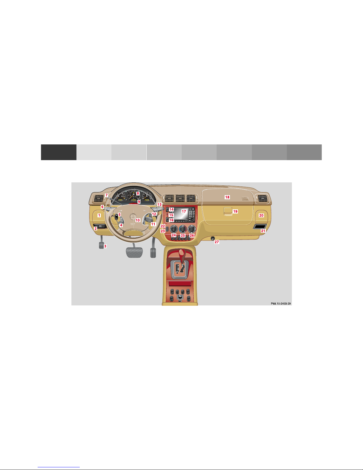
For more detailed descriptions se e index on page 300.
For adjustment of air outlets, refer to climate control,
see page 98.
1 Cup holder, see page 114
2 Parking brake release, see page 173
3 Parking brake pedal, see page 173
4 Steering wheel adjustment lever, see page 70
5 Headlamp washer switch, see page 94
6 Exterior lamp switch, see page 90
7 Cruise control switch, see page 196
8 Instrument cluster, see page 76
9 Hazard warning flasher switch, see page 94
10 Horn (with key in steering lock position 1 or 2),
Driver airbag, see page 56
11 Steering lock with ignition/ starter switch, see
page 162
12 Switch for exterior rear view mirrors, electrically
folding, see page 75
13 Windshield wiper/ washer switch, see page 95
14 Transmission control – LOW RANGE mode, see
page 209
15 Indicator lamp for antitheft alarm system
16 Auxiliary front fog lamp /rear fog lamp switch, see
page 92
17 MCS (Optional Modular Control System), see
separa te operator’s manual
18 Front passenger airbag, see page 56
19 Glove box (illuminated with key in steering lock
position 1 or 2)
20 Cup holder, see page 114
21 Storage compartment
22 Air recirculation switch, see page 98
23 Air conditioner on /off switch, see page 98
24 Air volume control switch
25 Temperature selector switch
26 Air distribution switch
27 Electrical outlet, see page 230
Ofrecido por www.electromanuales.com
20Instruments and controls
Tech nical
data
Instruments
and controls
Operation Driving
Instrument
cluster display
Practical hints Car care Index
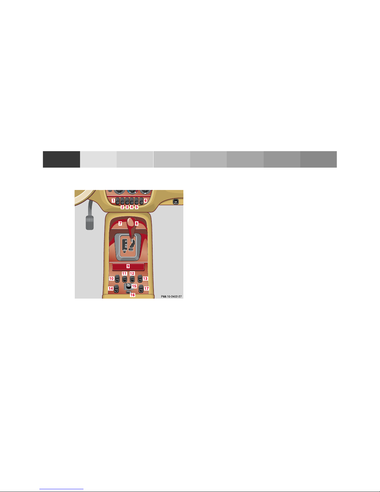
Center console 1 Left front seat heater switch, see page 44
2 Switch for rear quarter window, left, see page 106
3 Switch for rear window washer/wiper, see page 96
4 ESP control switch, see page 207
5 Switch for rear quarter window, right, see page 106
6 Right front seat heater switch, see page 44
7 Storage compartment
8 Selector lever, see page 165
9 Ashtray with lighter, see page 118
10 Power window switch, left front door, see page 104
11 Central locking switch, see page 32
12 Rear window defroster switch, see page 103
13 Power window switch, right front door, see page 104
14 Power window switch, left rear door, see page 104
15 Mirror adjustment switch, see page 73
16 Power window safety switch, rear doors, see
page 104
17 Power window switch, right rear door, see page 104
Ofrecido por www.electromanuales.com
21Instruments and controls
Tech nical
data
Instruments
and controls
Operation Driving
Instrument
cluster display
Practical hints Car care Index
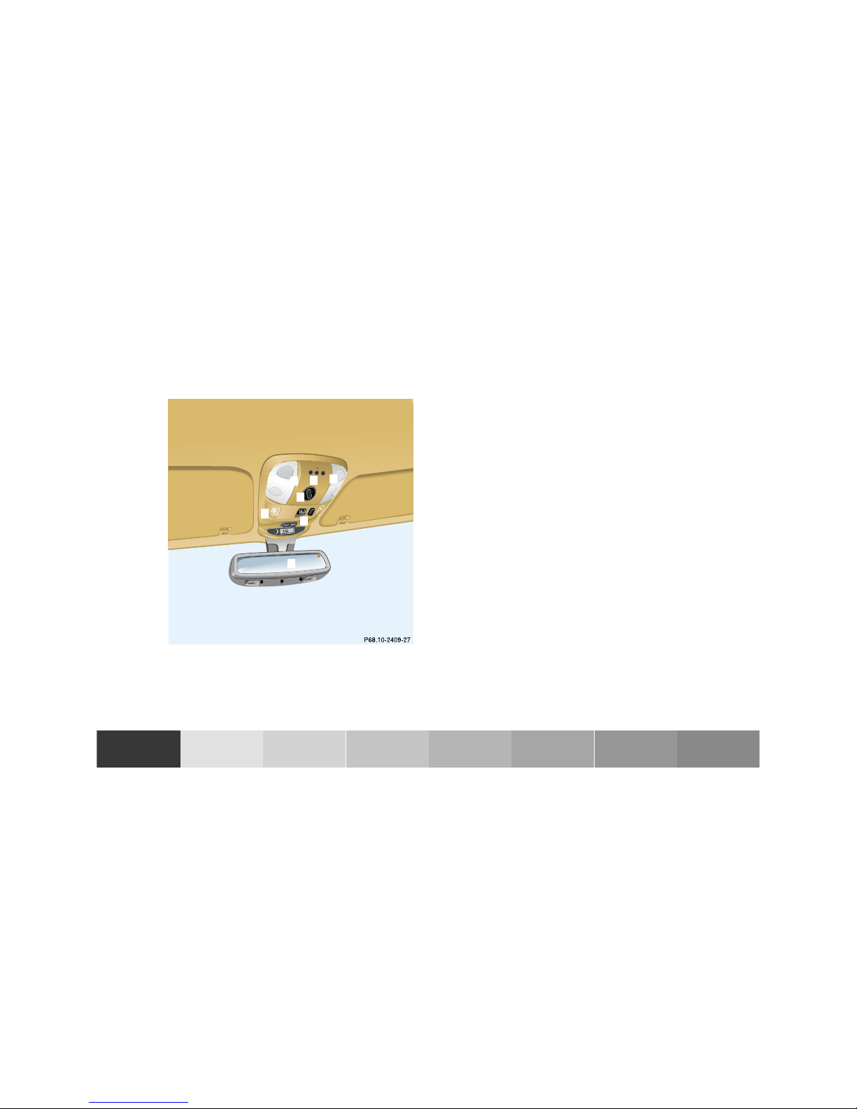
Overhead control panel 1 Interior lighting, see page 110
2 Garage door opener, see page 140
3 Hands-free microphone for Tele Aid, telephone and
voice recognition system
4 Tele Aid (emergency call system), see page 148
5 Sliding /pop-up roof, see page 107
Skyview Top, see page 109
6 Rear view mirror, see page 71
Reading lamps inside rear view mirror, see page 110
1
2
3
4
5
6
1
Ofrecido por www.electromanuales.com

22Contents - Operation
Tech nical
data
Instruments
and controls
Operation Driving
Instrument
cluster display
Practical hints Car care Index
Operation
Vehicle keys ......................................24
Start lock-out ....................................25
General notes on the
central locking system ...............26
Central locking system ...................26
Radio frequency
remote control ..............................26
Unlocking the liftgate ..................28
Panic button ..................................28
Mechanical keys ...........................29
Doors ..................................................30
Central locking switch ....................32
Automatic central locking ..........32
Emergency unlocking in case
of accident ....................................33
Liftgate ...............................................34
Antitheft alarm system ...................35
Tow-aw ay al ar m and
glass breakage sensor ................36
Seats, front ........................................37
Manual seats .................................39
Power seats ...................................40
Head restraint ...............................41
Heated seats ..................................... 44
Seat belts and integrated
restraint system .......................... 46
Seat belts .......................................... 46
Seat belt nonusage
warning system ............................ 47
BabySmart
TM
airbag
deactivation system ................... 53
Self-test BabySmart
TM
without special child
seat installed ................................ 53
Supplemental restraint
system (SRS) ............................... 54
Emergency tensioning
retractor (ETR) ............................ 55
Airbags .............................................. 56
Safety guidelines for the
seat belt, emergency
tensio ning retracto r
and airbag ..................................... 63
Infant and child
restraint systems ......................... 65
Adjustable steering wheel .............. 70
Inside rear view mirror ...................71
Antiglare night position .............. 71
Exterior rear view mirrors .............73
Exterior rear view mirror,
electrically folding .......................75
Instrument cluster ........................... 76
Indicator lamps in the
instrument cluster ......................78
Trip computer ...................................83
Flexible service system (FSS) ........87
Engine oil level indicator ................89
Exterior lamp switch .......................90
Fog lamp switch
(except Canada) ..........................92
Fog lamp switch
(Canada only) ..............................93
Hazard warning flasher
switch ............................................94
Headlamp cleaning system ............94
Windshield wiper/washer
switch ............................................95
Rear window wiper/washer ...........96
Climate control .................................98
Basic setting – Heater ...............100
Ofrecido por www.electromanuales.com

23Contents - Operation
Tech nical
data
Instruments
and controls
Operation Driving
Instrument
cluster display
Practical hints Car care Index
Basic setting –
Air conditioner ...........................100
Special setting ............................101
Dust filter ....................................102
Air recirculation .........................102
Rear window defroster ..............103
Power windows ...............................104
Rear quarter windows ................... 106
Sliding/pop-up roof .......................107
Skyview Top ....................................109
Interior lighting ..............................110
Sun visors ........................................113
Illuminated vanity mirrors ...........113
Interior .............................................114
Storage compartments,
armrest and cup holder ............114
Glove box ......................................115
Armrest in rear bench seat ...........117
Ashtrays ........................................... 118
Lighter ..............................................119
Split rear seat bench ..................... 120
Easy entry/exit feature ............. 123
Rear seat head restraints ......... 124
Third row seats ..............................126
Removable cargo floor plates .......129
Enlarged cargo area ....................... 131
Cargo tie-down rings .....................132
Hooks ...............................................133
Partition net ....................................133
Loading instructions .....................136
Cargo area cover blind ..................137
Telephone, general ........................139
Cellular telephone .........................139
Garage door opener .......................140
Ofrecido por www.electromanuales.com
24Central locking system
Tech nical
data
Instruments
and controls
Operation Driving
Instrument
cluster display
Practical hints Car care Index
Veh icle k eys
Included with your vehicle are:
• 2 remote controls with folding master keys,
• 1 reserve key,
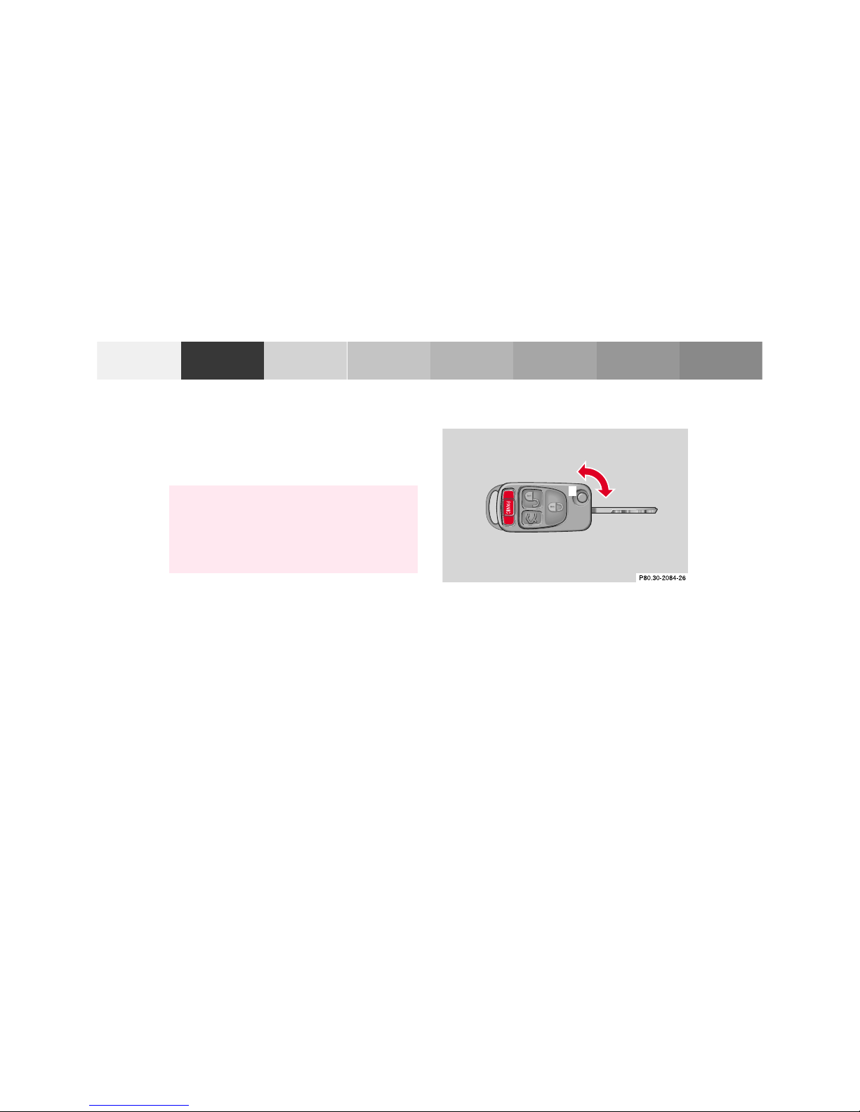
Remote control with folding master key
The remote control operates all locks on the vehicle.
To release the key, press button (1). The key unfolds
from the holder by itself.
The transmitter for the remote control is located in the
key h old er.
War ni ng!
When leaving the vehicle always remove the key
from the steering lock, and lock your vehicle. Do
not leave children unattended in the vehicle, or
with access to an unlocked vehicle. Unsupervised
use of vehicle equipment may cause serious
personal injury.
1
Ofrecido por www.electromanuales.com

25Central locking system
Tech nical
data
Instruments
and controls
Operation Driving
Instrument
cluster display
Practical hints Car care Index
Reserve key
The reserve key fits all locks on the vehicle.
For notes on the mechanical keys refer to page 29.
Note:
We recommend that you carry the reserve key with you
and keep it in a safe place (e.g. your wallet) so that it is
always handy. Never leave the reserve key in the
vehicle.
Obtaining replacement keys
Your vehicle is equipped with a theft deterrent locking
system requiring a special key manufacturing process.
For security reasons, replacement keys can only be
obtained from your authorized Mercedes-Benz Light
Truck Center.
Start lock-ou t
Importan t!
Removing the key from the steering lock activates the
start lock-out. The engine cannot be started.
Turning the key in the steering lock to position 2
deactivates the start lock-out.
Note:
In case the engine cannot be started and the
messages Á and î are shown in the odometer
display field, the system is not operational. Contact an
authorized Mercedes-Benz Light Truck Center or call
1-800-FOR-MERCedes (in the USA), or 1-800-387-0100
(in Canada).
Ofrecido por www.electromanuales.com

26Central locking system
Tech nical
data
Instruments
and controls
Operation Driving
Instrument
cluster display
Practical hints Car care Index
General notes on the central locking system
If the key in the steering lock is in position 1 or 2, the
vehicle cannot be locked or unlocked with the remote
control.
If the vehicle cannot be locked or unlocked:
• Check the batteries of the remote control, see
page 270.
• Synchronize the remote control, see page 271.
Central locking system
(Radio frequency remote control)
The master key has an integrated radio frequency
remote control.
Due to the extended operational range of the remote
control, it could be possible to unintentionally lock or
unlock the vehicle by pressing the transmit button.
The vehicle doors, liftgate and fuel filler flap can be
centrally locked and unlocked via remote control.
With vehicle centrally locked, the liftgate can also be
unlocked by using the remote control.
If the key in the steering lock is in position 1 or 2, the
vehicle cannot be locked or unlocked with the remote
control.
Ofrecido por www.electromanuales.com
27Central locking system
Tech nical
data
Instruments
and controls
Operation Driving
Instrument
cluster display
Practical hints Car care Index
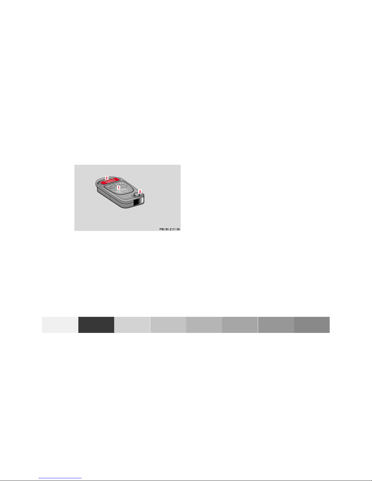
1 Transmit button
‹ Locking
ΠUnlocking
Š Unlocking liftgate
2 PANIC button
3 Release button for master key
Locking and unlocking with remote control
Unlocki ng:
Press transmit button Πonce. All turn signal lamps
blink once to indicate that the driver’s door and fuel
filler flap are unlocked.
The antitheft alarm system is also deactivated.
Press transmit button Πa second time to unlock
remaining doors and liftgate.
Notes:
If the fuel filler flap cannot be opened, see page 274.
If within 40 seconds of unlocking with the remote
control, neither door nor liftgate is opened or the key is
not inserted in the steering lock, the vehicle will
automatically lock and reactivate the antitheft alarm
system.
Ofrecido por www.electromanuales.com

28Central locking system
Tech nical
data
Instruments
and controls
Operation Driving
Instrument
cluster display
Practical hints Car care Index
Locking:
Press transmit button ‹ once. All turn signal lamps
blink three times to indicate that the vehicle is locked
and the antitheft alarm is activated.
Notes:
If the turn signal lamps do not blink three times when
locking the vehicle, a door, the liftgate, or the hood is
not properly closed. Close the respective element and
lock the vehicle again with the remote control.
If the vehicle cannot be locked or unlocked by pressing
the transmit button, then it may be necessary to change
the batteries in the remote control or to synchronize the
remote control, see page 270 and page 271.
Unlocking the liftgate
Press transmit button Š to unlock the liftgate. Thi s
also deactivates the antitheft alarm.
Important!
A minimum height clearance of 7 ft. (2.15 m) is
required to open the liftgate.
Panic button
To activate press and hold button (1) for at least one
second. An audible alarm and blinking turn signal
lamps will operate for approximately 3 minutes.
Additionally the interior ligh ts switch on automatically
for approximately 3 minutes.
To deactivate press button (1) again, or press transmit
button ‹, Œ or Š on the remote control, or
turn key in steering lock to position 1.
Ofrecido por www.electromanuales.com

29Central locking system
Tech nical
data
Instruments
and controls
Operation Driving
Instrument
cluster display
Practical hints Car care Index
Note:
For operation in the USA only: This device complies
with Part 15, Subpart C, Section 209 of the FCC Rules.
Operation is subject to the following two conditions:
(1) This device may not cause harmful interference, and
(2) this device must accept any interference received,
including interference that may cause undesired
operation.
WARNING: Changes or modification not expressly
approved by party responsible for compliance could void
the users’s authority to operate the equipment.
Mechanical keys
The mechanical keys fit all locks on the vehicle.
Notes:
Use of the key does not operate the central locking
system or arm or disarm the antitheft alarm system.
The alarm sounds when unlocking the door. Cancel
alarm by turning key in steering lock to position 1, or
with the remote control by pressing button Œ.
Ofrecido por www.electromanuales.com

30Central locking system
Tech nical
data
Instruments
and controls
Operation Driving
Instrument
cluster display
Practical hints Car care Index
Doors
1 Opening – pull handle
2 Unlocking driver’s door lock
3 Locking driver’s door lock
4 Individual door from inside:
Push lock button down to lock.
Pull lock button up to unlock.
5 Front door from inside:
Pull handle to unlock.
Importan t!
The mechanical key does not operate the central locking
system or arm or disarm the antitheft alarm system.
When you lock the driver’s door with the mechanical
key, the door lock button should move down.
P72.10-2103-26
Ofrecido por www.electromanuales.com

31Central locking system
Tech nical
data
Instruments
and controls
Operation Driving
Instrument
cluster display
Practical hints Car care Index
Each individual door and the liftgate must be locked
with the respective door lock button – the driver’s door
can only be locked when it is closed.
Notes:
The alarm sounds when unlocking the driver’s door.
Cancel alarm by turning key in steering lock to
position 1, or with the remote control by pressing
button Œ.
If the vehicle has previously been locked from the
outside, only the door being opened from the inside will
unlock, and the alarm will come on. The remaining
doors, the liftgate and fuel filler f lap remain locked.
In case of a malfunction in the central locking system
the doors can be locked and unlocked individually.
To lock, push down lock buttons and turn mechanical
key in driver’s door lock to position 3. In addition lock
the liftgate.
To unlock, pull inside door handles and turn mechanical
key in driver’s door lock to position 2.
Rear doors, previously centrally locked, can be opened
from inside by first unlocking the vehicle with the
central locking switch, see page 32, or by first pulling
up the door lock button.
If the fuel filler flap cannot be opened, see page 274.
Ofrecido por www.electromanuales.com

32Central locking system
Tech nical
data
Instruments
and controls
Operation Driving
Instrument
cluster display
Practical hints Car care Index
Central locking switch
1 Locking
2 Unlocking
The central locking switch is located on the center
console.
The doors and trunk can only be locked with the central
locking switch, if the front doors are closed.
If the vehicle was previously locked with the remote
control, the doors and liftgate cannot be unlocked with
the central locking switch.
Automatic central locking
The central locking switch also operates the automatic
central locking.
With the automatic central locking system activated and
the engine running, the doors and trunk are locked at
vehicle speeds of approximately 9 mph (15 km/ h) or
more.
To a cti vat e:
With key in steering lock position 2 hold upper portion
of switch (1) for a minimum of 5 seconds.
To deactivate:
With key in steering lock position 2 hold lower portion
of switch (2) for a minimum of 5 seconds.
Ofrecido por www.electromanuales.com

33Central locking system
Tech nical
data
Instruments
and controls
Operation Driving
Instrument
cluster display
Practical hints Car care Index
Notes:
If doors are unlocked with the central locking switch
after activating the automatic central locking, and
neither door is opened, then the doors remain unlocked
even at vehicle speeds of approximately 9 mph
(15 km/h) or more.
If a door is opened from the inside at speeds of
approximately 9mph (15km/h) or less with the
automatic central locking activated, the door will again
be automatically locked at speeds of approximately
9 mph (15 km/ h) or more.
Important!
When towing the vehicle, or with the vehicle on a
dynamometer test stand, please, note the following:
With the engine running, the vehicle doors will lock if
the left front wheel spins at vehicle speeds of
approximately 9 mph (15 km/ h) or more.
To prevent vehicle door locks from locking, deactivate
the automatic central locking.
Emergency unlocking in case of accident
The doo rs unlock automatically a short ti me af ter an
accident in which an airbag or emergency tensioning
retrac tor deploys (this is intended to aid rescue and
exit). However, the key must still be in the steering lock
position 1 or 2.
Additionally the hazard warning flashers turn on
automatically and the interior lights switch on for
approximately 30 minutes.
Ofrecido por www.electromanuales.com

34Central locking system
Tech nical
data
Instruments
and controls
Operation Driving
Instrument
cluster display
Practical hints Car care Index
Liftgate
1 Grip m olding
2 Handle, outside
3 Recessed grip
To o pen:
From outside of vehicle, pull on handle (2).
To close :
Pull down on recessed grip (3), and close by using the
grip molding (1).
1 Handle, inside
2 Locking
3 Unlocking
Importan t!
In case of danger, the unlocked liftgate can be opened
with the inside or outside handle.
Only drive with the liftgate closed as otherwise exhaust
fumes may enter the vehicle interior.
Ofrecido por www.electromanuales.com

35Antitheft alarm system
Tech nical
data
Instruments
and controls
Operation Driving
Instrument
cluster display
Practical hints Car care Index
Antitheft alarm system
The indicator lamp is located in the center console.
The antitheft alarm is automatically armed or disarmed
with the remote control by locking or unlocking the
vehicle.
The antitheft alarm is armed within approximately
15 seconds after locking the vehicle with the remote
control.
A blinking lamp in the center console indicates that the
alarm is armed.
Notes:
Use of the key in the front door locks does not arm or
disarm the antitheft alarm system.
The alarm sounds when unlocking the driver’s door
with the mechanical key. Cancel alarm by turning key in
steering lock to p osition 1, or with the remote control by
pressing button Œ.
If the vehicle battery voltage falls below 10 volts, the
alarm is automatically canceled and the antitheft alarm
system is disarmed. When the voltage is above this
value again, the antitheft alarm system is armed again.
Operation:
Once the alarm system has been armed, the turn signal
lamps will flash rapidly (approximately 3 minutes) and
the horn will sound intermittently (app roximately
30 seconds) when someone:
• opens a door,
• opens the liftgate,
• opens the hood,
• breaks a window,
• attempts to raise the vehicle.
The alarm will stay on even if the activating element (a
door, for example) is immediately closed.
If the alarm stays on for more than 20 seconds, an
emergency call is initiated automatically. See Tele Aid
on page 148.
Note:
The alarm system will cycle three times when triggered.
The interior lights are automatically switched on when
the alarm comes on and go out when canceling the
alarm.
Ofrecido por www.electromanuales.com

36Tow-away protection
Tech nical
data
Instruments
and controls
Operation Driving
Instrument
cluster display
Practical hints Car care Index
Tow-away alarm and glass breakage sensor
The switch is located in the overhead console.
The tow-away alarm and glass breakage sensor are part
of the antitheft alarm system.
Once the alarm system has been armed, the turn signal
lamps will f lash rapidly and the horn will sound when
someone attempts to raise the vehicle, or breaks a
window and reaches into the passenger compartment.
The alarm will last approximately 3 minutes in t he form
of rapidly flashing turn signal lamps. At the same time
the horn will sound for approximately 30 seconds. The
alarm will stay on even if the vehicle is immediately
lowered.
If the alarm stays on for more than 20 seconds, an
emergency call is initiated automatically. See Tele Aid
on page 148.
To prevent triggering the tow-away alarm feature, switch
off the tow-away alarm and glass breakage sensor before
towing the vehicle, or when parking on a surface subject
to movement, such as a ferry or auto train.
To do so, turn key in steering lock to position 1, then
return it to position 0 and remove key from steering
lock.
Within 30 seconds, push left or right button. (On
vehicles equipped with optional trip computer, push
RESET or MODE button, display shows OFF.)
Exit vehicle, and lock vehicle with remote control.
The tow-away alarm and glass breakage sensor remain
switched off until the key is inserted in steering lock
and turned to positi on 1.
Ofrecido por www.electromanuales.com

37Seats
Tech nical
data
Instruments
and controls
Operation Driving
Instrument
cluster display
Practical hints Car care Index
Seats, front
Caution!
Do not remove head restraints except when mounting
seat covers. For removal see page 43. Whenever head
restraints have been removed be sure to reinstall them
before driving.
War ni ng!
Do not adjust the driver’s seat while driving.
Adjusting the seat while driving could cause the
driver to lose control of the vehicle.
Never ride in a moving vehicle with the backrest
reclined. Sitting in an excessively reclined position
can be dangerous. You could slide under the seat
belt in a collision. If you slide under it, the belt
would apply force at the abdomen or neck. That
could cause serious or even fatal injuries. The
backrest and seat belt provide the best restraint
when the wearer is in an upright position and the
belt is properly positioned on the body.
Never place hands under seat or near any moving
parts while a seat is being adjusted.
War ni ng!
When leaving the vehicle always remove the key
from the steering lock, and lock your vehicle.
Do not leave children unattended in the vehicle or
with access to an unlocked vehicle. Unsupervised
use of vehicle equipment may cause serious
personal injury.
Ofrecido por www.electromanuales.com

38Seats
Tech nical
data
Instruments
and controls
Operation Driving
Instrument
cluster display
Practical hints Car care Index
Important!
Prior to operating the vehicle, the driver should adjust
the seat height for proper vision as well as fore/ aft
placement and backrest angle to insure adequate
control, reach, operation, and comfort. The head
restraint should also be adjusted for proper height. See
also airbag section on page 56 for proper seat
positioning.
In addition, also adjust the steering wheel to ensure
adequate control, reach, operation, and comfort.
Both the inside and outside rear view mirrors should be
adjusted for adequate rearward vision.
Fasten seat belts. Infants and small children should be
seated in a properly secured restraint system that
complies with U.S. Federal Motor Vehicle Safety
Standard 213 and Canadian Motor Vehicle Safety
Standard 213.
All seat, head restraint, steering wheel, and rear view
mirror adjustments as well as fastening of seat belts
should be done before the vehicle is put into motion.
War ni ng!
Children 12 years old and under must never ride in
the front seat, except in a Mercedes-Benz
authorized BabySmart
TM
compatible child seat,
which operates with the BabySmartTM system
installed in the vehicle to deactivate the passenger
side front airbag when it is properly installed.
Otherwise they will be struck by the airbag when it
inflates in a crash. If this happens, serious or fatal
injury can result.
According to accident statistics, children are safer
when properly restrained in the rear seating
positions than in the front seating positions.
Infants and small children must ride in the back
seats and be seated in an appropriate infant or
child restraint system, which is properly secured
with the vehicle’s seat belt, fully in accordance
with the child seat manufacturer’s instructions.
A child’s risk of serious or fatal injuries is
significantly increased if the child restraints are
not properly secured in the vehicle and the child is
not properly secured in the child restraint.
Ofrecido por www.electromanuales.com

39Seats
Tech nical
data
Instruments
and controls
Operation Driving
Instrument
cluster display
Practical hints Car care Index
Manual seats (ML 320)
We recommend to adjust the manual seat in the
following order:
1 Seat, fore/ aft
Lift handle (1), slide seat to desired position and
allow handle to reengage. Check for proper
engagement before driving. The position should be
as far rearward as possible, consistent with ability to
properly operate controls.
2 Seat cushion inclination adjustment
Raise lever (2), move seat cushion to desired
position. Release lever.
3 Backrest adjustment
Turn handwheel (3).
4 Head restraint height
Raising:
Pull up on head restraint.
Lowering:
Push button (4), located at top of seat back, and
push down on head restraint.
Adjust head restraint to support the back of the head
approximately at ear level. The head restraint angle
can also be adjusted manually.
See page 43 for removing head restraints.
Ofrecido por www.electromanuales.com

40Seats
Tech nical
data
Instruments
and controls
Operation Driving
Instrument
cluster display
Practical hints Car care Index
Power seats (standard; optional on model ML 320)
The slide switches are located on the entry side of each
front seat base.
Turn key in steering lock to position 1 or 2 (with the
driver’s or passenger’s door open, the power seats can
also be operated with the key removed or in steering
lock position 0).
We recommend to adjust the power se at in the following
order:
1 Seat, up/ down
Press the switch (up/down direction) until
comfortable seating position with still sufficient
headroom is reached.
2 Seat adjustment, fore/aft
Press the switch (fore/aft direction) until a
comfortable seating position is reached that still
allows you to reach the accelerator / brake pedal
safely. The position should be as far rearward as
possible, consistent with ability to properly operate
controls.
3 Seat cushion tilt
Press the switch in the direction of the arrow until
your legs are lightly supported.
4 Backrest tilt
Press the switch in the direction of the arrow until
your arms are slightly angled when holding the
steering wheel.
Ofrecido por www.electromanuales.com

41Seats
Tech nical
data
Instruments
and controls
Operation Driving
Instrument
cluster display
Practical hints Car care Index
Only minor personal adjustments, as described below,
should then be required.
For exterior rear view mirrors, see page 73;
inside rear view mirror, see page 71;
steering wheel adjustment, see page 70.
Note:
See page 42 for instructions on storing and recalling the
seat position.
Head restraint
Raising:
Pull up on head restraint.
Lowering:
Push button, located at top of seat back, and push down
on head restraint, see also page 43.
Adjust head restraint to support the back of the head
approximately at ear level. The he ad restraint angle can
also be adjusted manually.
See page 43 for removing head restraints.
War ni ng!
When leaving the vehicle always remove the key
from the steering lock, and lock your vehicle.
The power seats can also be operated with the
driver’s or passenger door open. Do not leave
children unattended in the vehicle or with access
to an unlocked vehicle. Unsupervised use of vehicle
equipment may cause serious personal injury.
Ofrecido por www.electromanuales.com

42Seats
Tech nical
data
Instruments
and controls
Operation Driving
Instrument
cluster display
Practical hints Car care Index
Memory storing and recalling
(optional on model ML 320 and ML 430)
5 Memory button
6 Position buttons
Storing
Three sets of seat positions may be programmed into
memory. After the seat is positioned, push memory
button (5), release, and within 3 seconds push position
button “1”. A second and third set of positions for the
same seat can be programmed into memory by pushing
first memory button (5) and then position button “2”,
respectively “3”.
Recalling
To recall a seat position, push and hold one of the
position buttons “1”, “2” or “3” until seat movement has
stopped. The seat movement stops when the respective
position button is released.
Caution!
Do not operate the power seats using the memory
button if the seat backrest is in an excessively reclined
position. Doing so could cause damage to front or rear
seats.
First move the backrest to an upright position.
Ofrecido por www.electromanuales.com

43Seats
Tech nical
data
Instruments
and controls
Operation Driving
Instrument
cluster display
Practical hints Car care Index
Head restraint removal
Removal:
Pull head restraint to its highest position. Push lock
button (arrow) and pull out head restraint completely
with both hands.
Installation:
Insert the head restraint and push it down to the stop.
Push lock button (arrow) and adjust head restraint down
to the desired position.
Ensure proper head restraint positioning, see above.
War ni ng!
For your protection, drive only with properly
positioned head restraints.
Adjust head restraint to support the back of the
head approximately at ear level.
Do not drive the vehicle without the seat head
restraints. Head restraints are intended to help
reduce injuries during an accident.
Ofrecido por www.electromanuales.com

44Seats
Tech nical
data
Instruments
and controls
Operation Driving
Instrument
cluster display
Practical hints Car care Index
Heated seats (front, optional on ML 320)
The front seat heater switches are located on the center
console.
The front seat heaters can be switched on with the
engine running.
Press switch to turn on seat heater:
1 Normal seat heating mode. One indicator lamp in
the switch lights up.
2 Rapid seat heating mode. Both indicator lamps in
the switch light up.
After approximately 5 minutes in the rapid seat
heating mode, the seat heater automatically
switches to normal operation and only one indicator
lamp will stay on.
Turnin g off se at heater:
If one indicator lamp is on, press upper half of switch.
If both indicator lamps are on, press lower half of
switch.
If left on, the seat heater automatically turns off after
approximately 20 minutes of operation.
P54.25-2036-26
1
2
Ofrecido por www.electromanuales.com

45Seats
Tech nical
data
Instruments
and controls
Operation Driving
Instrument
cluster display
Practical hints Car care Index
Notes:
When in operation, the seat heater consumes a large
amount of electrical power. It is not advisable to use the
seat heater longer than necessary.
The seat heaters may automatically switch off if too
many power consumers are switched on at the same
time, or if the battery charge is low. When this occurs,
the indicator lamps in the switch will blink for
approximately 30 seconds.
Within this time the seat heaters will switch on again
automatically as soon as sufficient voltage is available.
After approximately 30 seconds without sufficient
voltage the seat heaters switch off (indicator lamps go
out).
Ofrecido por www.electromanuales.com

46Restraint systems
Tech nical
data
Instruments
and controls
Operation Driving
Instrument
cluster display
Practical hints Car care Index
Seat belts and integrated restraint system
Your vehicle is equipped wit h seat belts for all seats,
emergency tensioning retractors for front and second
row outboard seat belts, dual front airbags and door
mounted side impact airbags. Their protective functions
are designed to complement one another.
Seat belts
Important!
Laws in most states and all Canadian provinces require
seat belt use.
All states and provinces require use of child restraints
that comply with U.S. Federal Motor Vehicle Safety
Standard 213 and Canadian Motor Vehicle Safety
Standard 213.
All child restraint systems are designed to be secured in
vehicle seats by lap belts or the lap belt portion of a lapshoulder belt.
For your safety and that of your passengers we strongly
recommend their use.
War ni ng!
Children 12 years old and under must never ride in
the front seat, except in a Mercedes-Benz
authorized BabySmart
TM
compatible child seat,
which operates with the BabySmartTM system
installed in the vehicle to deactivate the passenger
side front airbag when it is properly installed.
Otherwise they will be struck by the airbag when it
inflates in a crash. If this happens, serious or fatal
injury will result.
According to accident statistics, children are safer
when properly restrained in the rear seating
positions than in the front seating positions.
Infants and small children must ride in back seats
and be seated in an appropriate infant or child
restraint system, which is properly secured with
the vehicle’s seat belt, fully in accordance with the
child seat manufacturer’s instructions.
A child’s risk of serious or fatal injuries is
significantly increased if the child restraints are
not properly secured in the vehicle and the child is
not properly secured in the child restraint.
Ofrecido por www.electromanuales.com

47Restraint systems
Tech nical
data
Instruments
and controls
Operation Driving
Instrument
cluster display
Practical hints Car care Index
Note:
For cleaning and care of the seat belts, see page 282.
Seat belt nonusage warning system
After starting the engine, a warning sounds and the seat
belt warning lamp < remains illuminated for a short
time if the driver’s seat belt is not fastened.
War ni ng!
Never ride in a moving vehicle with the backrest
reclined. Sitting in an excessively reclined position
can be dangerous. You could slide under the seat
belt in a collision. If you slide under it, the belt
would apply force at the abdomen or neck. That
could cause serious or even fatal injuries. The
backrest and seat belt provide the best restraint
when the wearer is in an upright position and the
belt is properly positioned on the body.
War ni ng!
Failure to wear and properly fasten and position
your seat belt greatly increases your risk of
injuries and their likely severity in an accident.
You and your passengers should always wear seat
belts.
If you are ever in an accident, your injuries can be
considerably more severe without your seat belt
properly buckled. Without your seat belt buckled,
you are much more likely to hit the interior of the
vehicle or be ejected from it. You can be seriously
injured or killed.
In the same crash, the possibility for injury or
death is lessened if you are wearing your seat belt.
War ni ng!
Never let more people ride in the vehicle than there
are seat belts available. Be sure everyone riding in
the vehicle is correctly restrained with a separate
seat belt.
Ofrecido por www.electromanuales.com

48Restraint systems
Tech nical
data
Instruments
and controls
Operation Driving
Instrument
cluster display
Practical hints Car care Index
Fastening of seat belts
1 Latch plate
2 Buckle
3 Release button
Push latch plate (1) into buckle (2) until it clicks. Do not
twist the belt. A twisted seat belt may cause injury.
To help avoid severe or fatal injuries, the lap belt must
be positioned as low as possible on your hips and not
across the abdomen.
War ni ng!
Always fasten your seat belt before driving off.
Always make sure your passengers are properly
restrained – even those sitting in the rear.
Ofrecido por www.electromanuales.com

49Restraint systems
Tech nical
data
Instruments
and controls
Operation Driving
Instrument
cluster display
Practical hints Car care Index
Tighten the lap portion to a snug fit by pulling shoulder
portion up.
The shoulder portion of the seat belt must be pulled
snug and checked for snugness immediately after
engaging it.
Adjust seat belt so that shoulder portion is located as
close as possible to the middle of your shoulder (it
should not touch the neck). For this purpose, you can
adjust the height of the belt outlet. Three positions are
available.
4 Button for belt outlet height adjustment
To raise, slide belt height adjustment upward.
To lower, press button (4) and slide belt outlet
downward.
Caution!
For safety reasons, avoid adjusting the seat or backrest
into positions which could affect the correct seat belt
positioning.
Ofrecido por www.electromanuales.com

50Restraint systems
Tech nical
data
Instruments
and controls
Operation Driving
Instrument
cluster display
Practical hints Car care Index
Operation
The inertia reel stops the belt from unwinding during
sudden vehicle stops or when quickly pulling on the
belt. The locking function of the reel may be checked by
quickly pulling out the belt.
Unfastening of seat belts
Push the release button (3) in the belt buckle (2).
Allow the retractor to completely rewind the seat belt by
guiding the latch plate (1).
War ni ng!
USE SEAT BELTS PROPERLY.
• Seat belts can only work when used properly.
Never wear seat belts in any other way than as
described in this section, as that could result
in serious injuries in case of an accident.
• Each occupant should wear their seat belt at all
times, because seat belts help reduce the
likelihood of and potential severity of injuries
in accidents, including rollovers. The
integrated restraint system includes “SRS”
(driver airbag, front passenger airbag, front
and rear door mounted side impact airbags),
“ETR” (seat belt emergency tensioning
retractors for the outboard passenger seats
[except in the optional 3rd row seats]), and
front seat knee bolsters. The system is
designed to enhance the protection offered to
properly belted occupants in certain frontal
(front airbags) and side (side impact airbags)
impacts which exceed preset deployment
thresholds.
Ofrecido por www.electromanuales.com

51Restraint systems
Tech nical
data
Instruments
and controls
Operation Driving
Instrument
cluster display
Practical hints Car care Index
• Never wear the shoulder belt under your arm,
against your neck or off your shoulder. In a
crash, your body would move too far forward.
That would increase the chance of head and
neck injuries. The belt would also apply too
much force to the ribs or abdomen, which
could severely injure internal organs such as
your liver or spleen.
• Never wear belts over rigid or breakable
objects in or on your clothing, such as
eyeglasses, pens, keys etc., as these might
cause injuries.
• Position the lap belt as low as possible on your
hips and not across the abdomen. If the belt is
positioned across your abdomen, it could cause
serious injuries in a crash.
• Each seat belt should never be used for more
than one person at a time. Do not fasten a seat
belt around a person and another person or
other objects.
• Belts should not be worn twisted. In a crash,
you wouldn’t have the full width of the belt to
manage impact forces. The twisted belt against
your body could cause injuries.
• Pregnant women should also use a lapshoulder belt. The lap belt portion should be
positioned as low as possible on the hips to
avoid any possible pressure on the abdomen.
• Never place your feet on the instrument panel
or on the seat. Always keep both feet on the
floor in front of the seat.
Ofrecido por www.electromanuales.com

52Restraint systems
Tech nical
data
Instruments
and controls
Operation Driving
Instrument
cluster display
Practical hints Car care Index
War ni ng!
USE CHILD RESTRAINTS PROPERLY.
Children 12 years old and under must never ride in
the front seat, except in a Mercedes-Benz
authorized BabySmart
TM
compatible child seat,
which operates with the BabySmart
TM
system
installed in the vehicle to deactivate the passenger
front airbag when it is properly installed.
Otherwise they will be struck by the airbag when it
inflates in a crash. If this happens, serious or fatal
injury will result.
According to accident statistics, children are safer
when properly restrained in the rear seating
positions than in the front seating positions.
Infants and small children must ride in back seats
and be seated in an appropriate infant or child
restraint system, which is properly secured with
the vehicle’s seat belt, fully in accordance with the
child seat manufacturer’s instructions.
A child’s risk of serious or fatal injuries is
significantly increased if the child restraints are
not properly secured in the vehicle and the child is
not properly secured in the child restraint.
Children too big for child restraint systems must
ride in back seats using regular seat belts. Position
shoulder belt across chest and shoulder, not face or
neck. A booster seat may be necessary to achieve
proper belt positioning.
Ofrecido por www.electromanuales.com

53Restraint systems
Tech nical
data
Instruments
and controls
Operation Driving
Instrument
cluster display
Practical hints Car care Index
BabySmart
TM
airbag deactivation system
Special BabySmart
TM
compatible child seats, designed
for use with the Mercedes-Benz system and available at
any authorized Mercedes-Benz Center are required for
use with the BabySmart
TM
airbag deactivation system.
With the special child seat properly installed, the
passenger front airbag will not deploy. The 7
indicator lamp located in the instrument cluster will be
illuminated, except with key removed or in steering lock
position 0. The system does not deactivate the door
mounted side impact airbag.
Self-test BabySmart
TM
without special child seat installed
After turning key in steering lock to position 1 or 2, the
7 indicator lamp located in the instrument cluster
comes on for approximately 6 seconds, extinguishes,
then blinks once.
If the indicator lamp should not come on or is
continuously lit, the system is not functioning. You must
see an authorized Mercedes-Benz Center before seating
any child on the front passenger seat.
BabySmartTM is a trademark of Siemens Automotive Corp.
War ni ng!
The BabySmart
TM
Airbag Deactivation System will
ONLY work with a special child seat designed to
operate with it. It will not work with child seats
which are not BabySmart
TM
compatible.
Never place anything between seat cushion and
child seat (e.g. pillow), since it reduces the
effectiveness of the deactivation system.
Follow the manufacturer’s instructions for
installation of special child seats.
The passenger side front airbag will not deploy
only if the 7 indicator lamp remains
illuminated.
Please be sure to check the indicator every time
you use the special system child seat.
Should the light go out while the restraint is
installed, please check installation. If the light
remains out, do not use the BabySmart
TM
restraint
to transport children on the front passenger seat
until the system has been repaired.
Ofrecido por www.electromanuales.com

54Restraint systems
Tech nical
data
Instruments
and controls
Operation Driving
Instrument
cluster display
Practical hints Car care Index
Supplemental restraint system (SRS)
Airbags are intended as a supplement to seat belts.
Airbags alone cannot protect as well as airbags plus
seat belts in impacts for which the airbags were
designed to operate, and do not af ford any protection
whatsoever in crashes for which the airbags are not
designed to deploy.
The SRS uses two c rash severity levels (thresholds) to
activate either the Emergency Tensioning Retractor
(ETR) or front airbag or both. Activation depends on t he
direction and severity of the impact exceeding the
preset thresholds and whether the seat belt is fastened.
Seat belt fastened
• first threshold exceeded: ETR activates
• second threshold exceeded: airbag also activates
Seat belt not fastened
Front seats:
• first threshold exceeded:
airbag activates, but not ETR
Rear outer seats:
• first threshold exceeded:
ETR activates
Driver, front passenger and rear outer seat systems
operate independently of each other.
Ofrecido por www.electromanuales.com

55Restraint systems
Tech nical
data
Instruments
and controls
Operation Driving
Instrument
cluster display
Practical hints Car care Index
Emergency tensioning retractor (ETR)
The seat belts for the outboard passenger seats (except
in the optional 3rd row seats) are equipped with
emergency tensioning retractors. These tensioning
retractors are located in each belt’s inertia reel and
become operationally ready with the key in steering
lock position 1 or 2.
The emergency tensioning retractors are designed to
activate only when the seat belts are fastened during
frontal impacts exceeding the first threshold of the SRS
and in rear impacts exceeding a preset severity level.
They remove slack from the belts in such a way that the
seat belts fit more snugly against the body restricting its
forward movement as much as possible.
In cases of other frontal impacts, angled impacts, rollovers, certain side impacts, or other accidents without
sufficient frontal or rear impact forces, the emergency
tensioning retractors will not be activated. The driver
and passengers will then be protected by the fastened
seat belts and inertia reel in the usual manner.
For seat belt and emergency tensioning retractor see
page 63.
Ofrecido por www.electromanuales.com

56Restraint systems
Tech nical
data
Instruments
and controls
Operation Driving
Instrument
cluster display
Practical hints Car care Index
Airbags
1 Driver airbag
The most effective occupant restraint system yet
developed for use in production vehicles is the seat belt.
In some cases, however, the protective effect of a seat
belt can be further enhanced by an airbag.
The driver airbag is located in the steering wheel hub.
2 Front passenger airbag
The passenger front airbag is located in the dashboard
ahead of the front passenger.
Ofrecido por www.electromanuales.com

57Restraint systems
Tech nical
data
Instruments
and controls
Operation Driving
Instrument
cluster display
Practical hints Car care Index
3 Side impact airbag, front
The side impact airbags are located in the front and rear
doors.
In conjunction with wearing the seat belts, the driver
and front passenger airbags can provide increased
protection for the driver and front passe nger in certain
frontal impacts exceeding preset thresholds.
4 Side impact airbag, rear
Door mounted side impact airbags can provide
increased protection to belted outboard occupants on
the impacted side of the vehicle in side impacts
exceeding its preset threshold.
Importan t!
The operational readiness of the airbag system is
verified by the indicator lamp “SRS” in the instrument
cluster when turning the key in steering lock to
position 1 or 2. If no fault is detected, the lamp will go
3
Ofrecido por www.electromanuales.com

58Restraint systems
Tech nical
data
Instruments
and controls
Operation Driving
Instrument
cluster display
Practical hints Car care Index
out after approximately 5 seconds; after the lamp goes
out, the system continues to monitor the components
and circuitry of the airbag system and will indicate a
malfunction by coming on again. If the lamp does not
come on at all or if it fails to extinguish after
approximately 5 seconds or if it comes on thereafter,
a malfunction in the system has been detected.
The following system components are monitored or
undergo a self-check: crash-sensor(s), airbag ignition
circuits, front seat belt buckles, emergency tensioning
retractors, seat sensor.
Initially, when the key is turned from steering lock
position 0 to positions 1 or 2, malfunctions in the
crash-sensor are detected and indicated (the “SRS”
indicator lamp stays on longer than 5 seconds or does
not come on).
Have the system checked at your authorized
Mercedes-Benz Light Truck Center immediately.
In the operational mode, after the indicator lamp has
gone out following the initial check, interruptions or
short circuits in the airbag ignition circuit and in the
driver and front passenger seat belt buckle harnesses,
and low voltage in the entire system are detected and
indicated.
War ni ng!
In the event a malfunction of the “SRS” is indicated
as outlined above, the “SRS” may not be
operational. For your safety, we strongly
recommend that you visit an authorized
Mercedes-Benz Light Truck Center immediately to
have the system checked; otherwise the “SRS” may
not be activated when needed in an accident, which
could result in serious or fatal injury, or it might
deploy unexpectedly and unnecessarily which
could also result in injury.
Ofrecido por www.electromanuales.com

59Restraint systems
Tech nical
data
Instruments
and controls
Operation Driving
Instrument
cluster display
Practical hints Car care Index
Front airbags
The driver and front passenger front airbags are
designed to activate only in certain frontal impacts
exceeding a preset threshold.
The front passenger airbag deploys only if the front
passenger seat is occupied and the ü indicator lamp
in the instrum ent cluster is not illuminated.
Note:
Heavy objects on the front passenger seat can appear to
the “SRS” to indicate the presence of an occupant in
that seat which causes the passenger front airbag to
deploy in a crash exceeding the appropriate threshold.
Side impact airbags
The side impact airbags are designed to activate only in
certain side impacts exceeding a preset threshold. Only
the side impact airbags on the impacted side of the
vehicle deploy.
The side impact airbag for the front passenger deploys
only if the front passenger seat is occupied.
Side impact airbags operate best in conjunction with a
properly positioned and fastened seat belt.
Note:
Heavy objects on front passenger seat can cause the
side impact airbag to deploy in a crash.
Importan t!
Airbags are designed to activate only in certain
frontal (front airbags) impacts, or side (side impact
airbags) impacts which exceed preset thresholds.
Only during these types of impacts, if of sufficient
severity to meet the deployment thresholds, will
they provide their supplemental protection.
The driver and passenger should always wear their
seat belts, otherwise it is not possible for the airbags
to provide their intended supplemental protection.
In cases of other frontal impacts, angled impacts,
roll-overs, other side impacts, rear collisions, or
other accidents in which the airbags are not
designed to deploy, the airbags will not be activated.
The driver and passenger will then be protected by
the fastened seat belts.
We caution you not to rely on the presence of the
airbags in order to avoid wearing your seat belt.
Ofrecido por www.electromanuales.com

60Restraint systems
Tech nical
data
Instruments
and controls
Operation Driving
Instrument
cluster display
Practical hints Car care Index
Your vehicle was originally equipped with airbags
which are designed to activate in certain impacts
exceeding a preset threshold to reduce the potential
and severity of injury. It is important to your safety
and that of your passenger that you replace deployed
airbags and repair any malfunctioning airbags to
ensure the vehicle will continue to provide crash
protection for occupants.
War ni ng!
Airbags are designed to reduce the potential of
injury in certain frontal (front airbags) impacts,
and side (side impact airbags) impacts which may
cause significant injuries, however, no system
available today can totally eliminate injuries and
fatalities.
The activation of the “SRS” temporarily releases a
small amount of dust from the airbags. This dust,
however, is neither injurious to your health, nor
does it indicate a fire in the vehicle. The dust might
cause some temporary breathing difficulty for
people with asthma or other breathing trouble. To
avoid this, you may wish to get out of the vehicle as
soon as it is safe to do so. If you have any breathing
difficulty but cannot get out of the vehicle after the
airbag inflates, then get fresh air by opening a
window or door.
War ni ng!
To reduce the risk of injury when the front airbags
inflate, it is very important for the driver and front
passenger to always be in a properly seated
position and to wear their seat belts.
For maximum protection in the event of a collision
always be in normal seated position with your back
against the backrest. Fasten your seat belt and
ensure that it is properly positioned on your body.
Since the airbag inflates with considerable speed
and force, a proper seating and hands on steering
wheel position will help to keep you at a safe
distance from the airbag. Occupants who are
unbelted, out of position or too close to the airbag
can be seriously injured by an airbag as it inf lates
with great force in the blink of an eye:
Ofrecido por www.electromanuales.com

61Restraint systems
Tech nical
data
Instruments
and controls
Operation Driving
Instrument
cluster display
Practical hints Car care Index
• Sit properly belted in an upright position with
your back against the backrest.
• Adjust the driver’s seat as far as possible
rearward, still permitting proper operation of
vehicle controls. The distance from the center
of the driver’s breastbone to the center of the
airbag cover on the steering wheel must be at
least ten inches (25 cm) or more. You should be
able to accomplish this by a combination of
adjustments to the seat and steering wheel. If
you have any problems, please see your
authorized Mercedes-Benz Light Truck Center.
• Do not lean with your head or chest close to the
steering wheel or dashboard.
• Keep hands on the outside of steering wheel
rim. Placing hands and arms inside the rim
can increase the risk and potential severity of
hand/ arm injury when the driver front airbag
inflates.
• Adjust the front passenger seat as far as
possible rearward from the dashboard when
the seat is occupied.
• Occupants, especially children, should never
lean their heads in the area of the door where
the side airbag inflates. This could result in
serious injuries or death should the airbag be
triggered. Always sit upright, properly use the
seatbelts and appropriate size infant or child
restraint system.
• Children 12 years old and under must never
ride in the front seat, except in a
Mercedes-Benz authorized BabySmart
TM
compatible child seat, w hich operates with the
BabySmart
TM
system installed in the vehicle to
deactivate the passenger side front airbag
when it is properly installed. Otherwise they
will be struck by the airbag when it inflates in
a crash. If this happens, serious or fatal injury
can result.
Failure to follow these instructions can result in
severe or fatal injuries to you or other occupants.
Ofrecido por www.electromanuales.com

62Restraint systems
Tech nical
data
Instruments
and controls
Operation Driving
Instrument
cluster display
Practical hints Car care Index
War ni ng!
Accident research shows that the safest place for
children in an automobile is in the rear seat.
Should you choose to place a child 12 years old or
under in the front passenger seat of your vehicle,
you must properly use a BabySmart
TM
child
restraint which will turn off the passenger side
front airbag. BabySmart
TM
will not, however, turn
off the vehicle’s side impact airbag.
It should be noted that with respect to both front
and rear side impact airbags there is a possibility
for a side airbag related injury if occupants,
especially children, are not properly seated or
restrained when next to a side airbag which needs
to deploy rapidly in a side impact in order to do its
job.
To help avoid the possibility of injury, please follow
these guidelines: (1) occupants, especially
children, should never place their bodies or lean
their heads in the area of the door where the side
airbag inflates. This could result in serious
injuries or death should the side airbag be
activated; (2) always sit upright, properly use the
seat belts and use an appropriately sized infant or
child restraint system for all children 12 years old
or under; and (3) always wear seat belts properly.
If you believe that, even with the use of these
guidelines, it would be safer for your rear seat
occupants to have both rear door mounted side
airbags deactivated, then deactivation can be
accomplished upon your written election to do so at
your authorized Mercedes-Benz Center at an
additional cost. Please contact your local
authorized Mercedes-Benz Center or call our Client
Assistance Center at 1-800-FOR-MERCedes
(1-800-367-6372) for details.
Ofrecido por www.electromanuales.com

63Restraint systems
Tech nical
data
Instruments
and controls
Operation Driving
Instrument
cluster display
Practical hints Car care Index
Safety guidelines for the seat belt,
emergency tensioning retractor and airbag
War ni ng!
• Damaged seat belts or belts that were highly
stressed in an accident must be replaced and
their anchoring points must also be checked.
Use only belts installed or supplied by an
authorized Mercedes-Benz Light Truck Center.
• Do not pass belts over sharp edges.
• Do not make any modification that could
change the effectiveness of the belts.
• Airbags and ETR’s are designed to function on
a one-time-only basis. An airbag or emergency
tensioning retractor (ETR) that was activated
must be replaced.
• An airbag system component within the
steering wheel gets hot after the airbag has
inflated. Do not touch.
• Improper work on the system, including
incorrect installation and removal, can lead to
possible injury through an unintended
activation of the “SRS”.
• No modifications of any kind may be made to
any components or wiring of the “SRS”. This
includes changing or removing any component
or part of the “SRS”, the installation of
additional trim material, badges etc. over the
steering wheel hub, front passenger airbag
cover, or front door trim panels, and
installation of additional electrical/ electronic
equipment on or near “SRS” components and
wiring. Keep area between airbags and
occupants free of objects (e.g. packages,
purses, umbrellas, etc.).
Ofrecido por www.electromanuales.com

64Restraint systems
Tech nical
data
Instruments
and controls
Operation Driving
Instrument
cluster display
Practical hints Car care Index
When you sell the vehicle we strongly urge you to give
notice to the subsequent owner that it is equipped with
an “SRS” by alerting him to the applicable section in the
Operator’s Manual.
• In addition, through improper work there is
the risk of rendering the “SRS” inoperative or
causing unintended airbag deployment. Work
on the “SRS” must therefore only be performed
by an authorized Mercedes-Benz Light Truck
Center.
• For your protection and the protection of
others, when scrapping the airbag unit or
emergency tensioning retractor, our safety
instructions must be followed. These
instructions are available at your authorized
Mercedes-Benz Light Truck Center.
• Given the considerable deployment speed and
the textile structure of the airbags, there is the
possibility of abrasions or other injuries
resulting from airbag deployment.
Ofrecido por www.electromanuales.com

65Restraint systems
Tech nical
data
Instruments
and controls
Operation Driving
Instrument
cluster display
Practical hints Car care Index
Infant and child restraint systems
We recom mend t hat al l infants and children be proper ly
restrained at all times while the vehicle is in motion. All
lap-shoulder belts except the driver’s seat belt have
special seat belt retractors for secure fastening of child
restraints.
To fasten a child restraint follow child restraint
instructions for routing. Then pull shoulder belt out
completely and let it retract. During the seat belt
retraction a ratcheting sound can be heard to indicate
that the special seat belt retractor is activated. The belt
is now locked. Push down on child restraint to take up
any slack.
To deactivate, release seat belt buckle and let seat belt
retract completely. The seat belt can again be used in
the usual manner.
Note:
For child seats with mounting fittings for tether
anchorages refer to page 67 (installation of infant and
chi ld restra int system s) .
Importan t!
The use of infant or child restraints is required by law in
all 50 states and all Canadian provinces.
Infants and small children should be seated in an
appropriate infant or child restraint system properly
secured by a lap-shoulder belt, and that complies with
U.S. Federal Motor Vehicle Safety Standard 213 and
Canadian Motor Vehicle Safety Standard 213.
A statement by the child restraint manufacturer of
compliance with this standard can be found on the
instruction label on the restraint and in the instruction
manual provided with the restraint.
When using any infant or child restraint system, be sure
to carefully read and follow all manufacturer’s
instructions for installation and use.
Please read and observe warning labels affixed to inside
of vehicle and to infant or child restraints.
War ni ng!
Never release the seat belt buckle while vehicle is
in motion, since the special seat belt retractor will
be deactivated.
Ofrecido por www.electromanuales.com

66Restraint systems
Tech nical
data
Instruments
and controls
Operation Driving
Instrument
cluster display
Practical hints Car care Index
War ni ng!
Children 12 years old and under must never ride in
the front seat, except in a Mercedes-Benz
authorized BabySmart
TM
compatible child seat,
which operates with the BabySmartTM System
installed in the vehicle to deactivate the passenger
front airbag when it is properly installed.
Otherwise they will be struck by the airbag when it
inflates in a crash. If this happens, serious or fatal
injury can result.
According to accident statistics, children are safer
when properly restrained in the rear seating
positions than in the front seating positions.
Infants and small children must ride in back seats
and be seated in an infant or child restraint system,
which is properly secured with the vehicle’s seat
belt, fully in accordance with the child seat
manufacturer’s instructions.
Infants and small children should never share a
seat belt with another occupant. During an
accident, they could be crushed between the
occupant and seat belt.
Children too big for child restraint systems must
ride in back seats using regular seat belts. Position
shoulder belt across chest and shoulder, not face or
neck. A booster seat may be necessary to achieve
proper belt positioning for children from 41 lbs. to
the point where a lap/shoulder belt fits properly
without one.
When the child restraint is not in use, remove it
from the vehicle or secure it with the seat belt to
prevent the child restraint from becoming a
projectile in the event of an accident.
Ofrecido por www.electromanuales.com

67Restraint systems
Tech nical
data
Instruments
and controls
Operation Driving
Instrument
cluster display
Practical hints Car care Index
Installation of infant and child restraint systems
To secure a tether strap to the anchorage, securely
fasten the hook (1), which is part of the tether strap, to
the anchorage ring (2). For safety, please make sure that
the hook has attached to the ring beyond the safety
catch, as illustrated.
Vehicle without third row seats
3 Tether anchorages for second row seats
4 Tether anchorages for third row seats (optional)
This vehicle is provided with three tether
anchorages (3) for a top tether strap behind the
second row seats.
Note:
Do not use the tether anchorages (4) for a top tether
strap on a second row seat.
Ofrecido por www.electromanuales.com

68Restraint systems
Tech nical
data
Instruments
and controls
Operation Driving
Instrument
cluster display
Practical hints Car care Index
Vehicle with third row seats
3 Tether anchorages for second row seats
4 Tether anchorages for third row seats
This vehicle is provided with tether anchorages for a top
tether strap behind the second row seats (3) and the
third row seats (4).
We recommend to install infant and child restraints on
the third row seats.
When using the third row seats observe the following:
• Installation of infant and child restraint systems
with a top tether strap is allowed only on both third
row seats p lus the center second row seat.
• When using the center second row seat for a top
tether strap, the left third row seat should only be
used for a child restraint system, since exiting the
vehicle may not be possible in an emergency due to
the routing of the top tether strap.
To store the left third row seat, see page 126.
Ofrecido por www.electromanuales.com

69Restraint systems
Tech nical
data
Instruments
and controls
Operation Driving
Instrument
cluster display
Practical hints Car care Index
Important!
An infant and child restraint system must not be
installed on the right second row seat while a passenger
rides in a third row seat. Use of the easy-entry/ exit
feature is not possible. See page 123 for easy-entry/exit
feature.
Note:
When installing an infant or child restraint system with
a top tether strap on the left second row seat, the left
third row seat should not be occupied. For storage of the
left third row seat, see page 126.
Ofrecido por www.electromanuales.com

70Adjustable steering wheel
Tech nical
data
Instruments
and controls
Operation Driving
Instrument
cluster display
Practical hints Car care Index
Adjustable steering wheel Unlocki ng:
Move lever (1) down. The indicator lamp, located in the
instrument cluster, comes on.
Adjusti ng:
Move steering wheel up or down to desired position.
Locking:
Move lever (1) up. The indicator lamp, located in the
instrument cluster, goes out.
Importan t!
With the key in steering lock position 2, the indicator
lamp in the instrument cluster comes on. It should go
out when the engine is running.
If the indicator lamp does not go out after starting the
engine, the adjustable steering column is not locked
properly.
Do not drive the vehicle until you have properly locked
the steering column.
War ni ng!
Do not adjust the steering wheel while driving. The
steering wheel must be locked while driving.
Adjusting the steering wheel while driving, or
driving without the steering wheel locked could
cause the driver to lose control of the vehicle.
Ofrecido por www.electromanuales.com

71Rear view mirrors
Tech nical
data
Instruments
and controls
Operation Driving
Instrument
cluster display
Practical hints Car care Index
Inside rear view mirror Use your inside mirror to determine the size and
distance of objects seen in the passenger side convex
mirror.
Antiglare night position
Manual:
Tilt the mirror to the antiglare night position using the
lever (1) at its lower edge.
Ofrecido por www.electromanuales.com

72Rear view mirrors
Tech nical
data
Instruments
and controls
Operation Driving
Instrument
cluster display
Practical hints Car care Index
Automatic (optional on ML 320):
With the key in steering lock position 2 and the
automatic antiglare function activated, the mirror
reflection brightness responds to changes in light
sensitivity.
To a ct iva te :
Press button (1). The green indicator lamp in the rear
view mirror lights up.
To deactivate:
Press button (1) again. The indicator lamp in the rear
view mirror goes out. The mirror brightness does not
respond to changes in light sensitivity.
Notes:
With gear selector lever in position “R”, or with the
interior lamps (except cargo compartment lamp)
switched on, the mirror brightness does not respond to
changes in light sensitivity.
The automatic antiglare function does not react, if
incoming light is not aimed directly at sensors in the
mirror.
War ni ng!
In the case of an accident liquid electrolyte may
escape the mirror housing when the mirror glass
breaks.
Electrolyte has an irritating effect. Do not allow the
liquid come into contact with eyes, skin, clothing,
or respiratory system. In cases it does, immediately
flush affected area with water, and seek medical
help if necessary.
Ofrecido por www.electromanuales.com

73Rear view mirrors
Tech nical
data
Instruments
and controls
Operation Driving
Instrument
cluster display
Practical hints Car care Index
Exterior rear view mirrors
The switch is located on the center console.
Turn key in steering lock to position 1 or 2.
First select the mirror to be adjusted – turn switch:
1 Left mirror
2 Right mirror
To adjust, toggle the switch forward, backward or to
either side.
Note:
After turning off the engine the exterior rear view
mirrors can be operated with a front door opened or
with key in steering lock position 1 for approximately
30 minutes.
P82.00-2044-26
War ni ng!
Exercise care when using the passenger-side
mirror. The passenger-side exterior mirror is
convex (outwardly curved surface for a wider field
of view). Objects in mirror are closer than they
appear. Check your inside rear view mirror or
glance over your shoulder before changing lanes.
Ofrecido por www.electromanuales.com

74Rear view mirrors
Tech nical
data
Instruments
and controls
Operation Driving
Instrument
cluster display
Practical hints Car care Index
Vehicles with automatic antiglare function:
With the key in steering lock position 2, the driver’s
side mirror reflection brightness responds to changes in
light sensitivity.
With gear selector lever in position “R”, or with the
interior lamps (except cargo compartment lamp)
switched on, the driver’s side mirror brightness does
not respond to changes in light sensitivity.
Importan t!
Electrolyte drops coming into contact with the vehicle
paint finish can only be completely removed while in
their liquid state, by applying plenty of water.
Notes:
The exterior mirrors have electrically heated glass. The
heater switches on automatically, depending on outside
temperature.
If an exterior mirror housing is forcibly pivoted from its
normal position, it must be repositioned by applying
firm pressure until it snaps into place.
War ni ng!
In the case of an accident liquid electrolyte may
escape the mirror housing when the mirror glass
breaks.
Electrolyte has an irritating effect. Do not allow the
liquid come into contact with eyes, skin, clothing,
or respiratory system. In cases it does, immediately
flush affected area with water, and seek medical
help if necessary.
Ofrecido por www.electromanuales.com

75Rear view mirrors
Tech nical
data
Instruments
and controls
Operation Driving
Instrument
cluster display
Practical hints Car care Index
Exterior rear view mirror, electrically folding
(optional on ML 320 and ML 430)
The switch is located in the dashboard behind the
steering wheel.
1 Press switch to fol d mirror out
2 Press switch to fol d mirror in
If an exterior mirror housing is forcibly forced forward
or rearward (hit from the front or from the rear), press
lower half of the switch (2) until you hear a hitting
noise.
Press upper half of the switch (1) to fold mirror out.
You can adjust the exterior rear view mirrors again, see
page 73.
Notes:
The exterior rear view mirrors can vibrate if they are
not completely folded out.
Before running the vehicle through an automatic car
wash, fold the mirrors in, otherwise they might get
damaged.
After turning off the engine the exterior rear view
mirrors can be operated with a front door opened or
with key in steering lock position 1 for approximately
30 minutes.
P82.00-2016-26
1
2
Ofrecido por www.electromanuales.com

76Instrument cluster
Tech nical
data
Instruments
and controls
Operation Driving
Instrument
cluster display
Practical hints Car care Index
Instrument cluster
Ofrecido por www.electromanuales.com

77Instrument cluster
Tech nical
data
Instruments
and controls
Operation Driving
Instrument
cluster display
Practical hints Car care Index
1 Coolant temperature gauge, see page 81
2 Outside temperature indicator (optional), see
page 82
3 Fuel gauge with reserve and fuel cap placement
warning lamp, see page 220
4 Left turn signal indicator lamp, see exterior lamp
switch, page 90
5 Knob for odometer/trip odometer readout/ reset,
FSS indicator, and intensity of instrument lamps,
see page 80
6 4-ETS+ and ESP warning lamp, se e page 221
For 4-ETS+ (four wheel electronic traction system),
see page 203;
for ESP (electronic stability program), see page 205.
7 Speedometer
8 Selectable:
Trip odometer, see page 80
Main odometer, see page 80
FSS display, see page 87
Engine oil level indicator, see page 89
9 Right turn signal indicator lamp, see exterior lamp
switch, page 90
10 Knob for setting clock, see page 80
11 Tachometer, see page 82
12 Gear range indicator display, see selector lever
positions, page 168
13 Clock, see page 80
Ofrecido por www.electromanuales.com

78Instrument cluster
Tech nical
data
Instruments
and controls
Operation Driving
Instrument
cluster display
Practical hints Car care Index
Indicator lamps in the instrument cluster
High beam
BAS malfunction, see page 221
ESP malfunction, see page 221
4-ETS+ malfunction, see page 221
ABS malfunction, see page 222
Brake pads worn down, see page 225
Engine oil level low, see page 224
Coolant level low, see page 224
Transmission in LOW RANGE mode,
see page 221
ESP and 4-ETS+. Adjust driving to road
condition, see page 221
Brake fluid low, see page 219
EBP malfu nction, see page 204
Parking brake engaged, see page 173
Front passenger airbag automatically
switched off, see page 53
Front fog lamp, see page 92
Steering wheel adjustment not locked,
see page 70
Fasten seat belts,
see page 223
Battery not being charged properly,
see page 223
SRS malfu nction, see page 219
BAS
ESP
ABS
LOW
RANGE
BRAKE
SRS
Ofrecido por www.electromanuales.com

79Instrument cluster
Tech nical
data
Instruments
and controls
Operation Driving
Instrument
cluster display
Practical hints Car care Index
If the “CHECK ENGINE” malfunction
indicator lamp comes on when the engine is
running, it indicates a malfunction of the
fuel management system, emission control
system, systems which impact emissions, or
the fuel cap is not closed tight. In all cases,
we recommend that you have the
malfunction checked as soon as possible, see
page 218.
Additional function indicator lamps
(in the odometer display)
FSS indicator (Service A), see page 87
FSS indicator (Service B), see page 87
The symbols appear in the main odometer display field
prior to the next suggested service. Depending on
operating conditions throughout the year, the next
service is calculated and displayed in days or distance
remaining. See page 87 for notes on the flexible service
system (FSS).
CHECK
ENGINE
Ofrecido por www.electromanuales.com

80Instrument cluster
Tech nical
data
Instruments
and controls
Operation Driving
Instrument
cluster display
Practical hints Car care Index
Activating instrument cluster display
The display for temperature, odometer, oil level
indicator and clock is activated by:
• Opening the driver’s door.
• Pressing button (1) in the instrument cluster (with
key removed or in steering lock position 0).
• Turning the key in steering lock to position 1 or 2.
Display illumination
Rotate knob (1) to vary intensity of instrument lamps:
• Clockwise - instrument lamp intensity increases.
• Counterclockwise - instrument lamp intensity
decreases.
Odometer/trip odometer
Activate the instrum ent cluster.
• Press knob (1) once to switch to or from odometer to
trip odometer readout.
• Press and hold knob (1) for more than 1 second to
reset trip odometer (with trip odometer displayed).
• Press knob (1) twice to display next scheduled
service.
Clock
Adjusting clock (instrument cluster activated):
Minute: Pull out knob (2) and turn it to the right.
Hour: Pull out knob (2) and turn it to the left.
Ofrecido por www.electromanuales.com

81Instrument cluster
Tech nical
data
Instruments
and controls
Operation Driving
Instrument
cluster display
Practical hints Car care Index
Coolant temperature gauge
During severe operating conditions and stop-and-go city
traffic, the coolant temperature may rise close to the red
marking.
The engine should not be operated with the coolant
temperature in the red zone. Doing so may cause
serious engine damage which is not covered by the
Mercedes-Benz Limited Warranty.
War ni ng!
• Driving when your engine is badly overheated
can cause some fluids which may have leaked
into the engine compartment to catch fire. You
could be seriously burned.
• Steam from an overheated engine can cause
serious burns and can occur just by opening
the engine hood. Stay away from the engine if
you see or hear steam coming from it.
Turn off the engine, get out of the vehicle and do
not stand near the vehicle until it cools down.
Ofrecido por www.electromanuales.com

82Instrument cluster
Tech nical
data
Instruments
and controls
Operation Driving
Instrument
cluster display
Practical hints Car care Index
Outside temperature indicator
The temperature sensor is located in the front bumper
area. Due to its location, the sensor can be affected by
road or engine heat during idling or slow driving. This
means that the accuracy of the displayed temperature
can only be verified by comparison to a thermometer
placed next to the sensor, not by comparison to external
displays (e.g. bank signs etc.).
Adaptation to ambient temperature takes place in steps
and depends on the prevailing driving conditions (stopand-go or moderate, constant driving) and amount of
temperature change.
Tachometer
The tachometer displays the present engine speed in
revolutions per minute (RPM).
To help protect the engine, the fuel supply is interrupted
if the engine is operated above its specified limit.
War ni ng!
The outside temperature indicator is not designed
to serve as an Ice-Warning Device and is therefore
unsuitable for that purpose. Indicated
temperatures just above the freezing point do not
guarantee that the road surface is free of ice.
Ofrecido por www.electromanuales.com

83Trip computer
Tech nical
data
Instruments
and controls
Operation Driving
Instrument
cluster display
Practical hints Car care Index
Trip computer (standard; optional on model ML 320)
The trip computer is located in the overhead console.
Function keys are:
• RESET
• MODE
Note:
With engine not running, the display switches off
automatically 30 seconds after the last entry.
To select a mode:
With key in steering lock position 1 or 2, press MODE
key repeatedly to illuminate the display and scroll
through menu for one of the following options:
1. Date, see page 84.
2. Compass, see page 84.
3. Stop watch, see page 86.
4. Present fuel consumption – displays miles per
gallon or liters per 100 km.
5. Average fuel consumption – displays miles per
gallon or liters per 100 km, see page 86.
6. Distance remaining with fuel presently in tank.
Note:
The disp lay flashes wh en fuel supply drops to the
reserve level. The distance remaining is no longer
shown.
7. Language – Press RESET key until the desired
language is displayed. Depending on language
selected, information is displayed in that country’s
customary system. See page 86.
8. Trip computer switched off.
MODE
Ofrecido por www.electromanuales.com

84Trip computer
Tech nical
data
Instruments
and controls
Operation Driving
Instrument
cluster display
Practical hints Car care Index
To change an entry, select mode to be changed:
• Date –
Press RESET key, the month shown blinks. Now
press MODE key to advance to selected month.
Press RESET key again, the day shown blinks. Now
press MODE key to advance to selected day.
Press RESET key again, the year shown blinks. Now
press MODE key to advance to selected year.
Press RESET key again, the display stops blinking
and the date is set.
• Compass –
The compass displays the direction the vehicle is
traveling, such as N, NE, E, SE, S, SW, W or NW.
Note:
The presence of buildings, bridges, power lines and
large antenna masts can influence the displayed
values. Metallic or magnetic objects in or on the
vehicle can influence the accuracy of the compass.
To change the compass zones:
Determine the geographical point of the vehicle with the
aid of the zone maps below:
1. Turn key in steering lock to position 2.
2. Press MODE key repeatedly until the compass
display appears in the trip computer display.
3. Press RESET key to select the compass zone mode.
The zone selected last is shown in the display.
4. Press RESET key repeatedly until the correct
compass zone, as determined from the zone map, is
shown in the display.
5. Press MODE key twice to activate the new compass
zone and change back to compass display.
Ofrecido por www.electromanuales.com

85Trip computer
Tech nical
data
Instruments
and controls
Operation Driving
Instrument
cluster display
Practical hints Car care Index
Zone map North America Zone map South America
Ofrecido por www.electromanuales.com

86Trip computer
Tech nical
data
Instruments
and controls
Operation Driving
Instrument
cluster display
Practical hints Car care Index
To calibrate the compass:
If the vehicle was exposed to a significant magnetic
zone, such as high voltage power lines, the compass
may have to be calibrated.
Calibration of the compass should be done in an area
free of steel superstructures and power lines. All
electrical consumers (e.g. exterior lamps, climate
control, etc.) should be switched off, doors and liftgate
closed. Do not open or close the roof. An open door or
liftgate triggers the display “–––”.
1. Start and run the engine.
2. Press MODE key repeatedly until the compass
display appears in the trip computer display.
3. Press RESET key to select the compass zone display.
4. Press RESET repeatedly until the correct zone, as
determined from the zone map (see page 85), is
shown in the display.
5. Press MODE key, “CAL–” appears in the display.
6. Press and hold RESET for a minimum of 2 seconds.
7. Without interruption drive two or more full circles
at a speed between 3 mph (5 km / h) and 7 mph
(10 km/ h) during which the message “CAL” is
replaced with a compass bearing (e.g. N, SW etc.),
immediately followed by three full circles at the
same speed, with only the rear window defroster
switched on. The defroster can be switched off
again. The calibration of the compass is now
complete.
• Stop watch –
Press RESET key to start the count. Press again to
stop the count. Press and hold RESET key to reset
stop watch.
• Average fuel consumption –
Press RESET key to delete present reading.
• Language –
Press RESET key to set the language used in the
display.
Ofrecido por www.electromanuales.com

87Flexible service system
Tech nical
data
Instruments
and controls
Operation Driving
Instrument
cluster display
Practical hints Car care Index
Flexible service system (FSS)
(service indicator)
The FSS permits a flexible service schedule that is
directly related to the operating conditions of the
vehicle.
The symbol 9 or ´ appears in the main odometer
field prior to the next suggested service. Depending on
operating conditions throughout the year, the next
service is calculated and displayed in days or distance
remaining.
The display begins to appear either 30 days or
2000 miles/km prior to the next suggested service.
The symbols 9 or ´ indicate the type of service
to be performe d:
9 Service A
´ Service B
The message is displayed for approximately 10 seconds
when turning the key in steering lock to position 2, or
while driving when reaching the service warning
threshold.
The message can be canceled manually by pressing
button (1).
The next service due date is displayed either in days or
in miles, depending on you r driving style.
Once the suggested term has passed, the symbol 9
or ´ plus message, preceded by a – (minus symbol)
blinks every time when turning the key in steering lock
to position 2.
Calling up service indicator manually:
Activate the instrument cluster, see page 80.
Within 4 seconds press button (1) twice to call up the
FSS display for approximately 10 seconds.
Ofrecido por www.electromanuales.com

88Flexible service system
Tech nical
data
Instruments
and controls
Operation Driving
Instrument
cluster display
Practical hints Car care Index
Important!
The FSS indicator is not an engine oil level indicator.
See page 89 for engine oil level indicator.
Notes:
When disconnecting vehicle battery for one or more
days at a time, such days will not be counted. Any such
days not counted by the FSS can be added by your
Mercedes-Benz Light Truck Center.
The interval between services is determined by the type
of driving for which the vehicle is used. For example,
driving at extreme speeds, and cold starts combined
with short distance driving in which the engine does not
reach normal operating temperature, reduce the interval
between services.
Following a completed A or B service the MercedesBenz Light Truck Center sets the counter mileage to
10 000 miles (Canada: 15 000 km) and 365 days.
The counter can also be set by any individual. To do so:
1. Turn the key in steering lock to position 2.
2. Immediately press button (1) twice within one
second.
3. The present status for days or distance is displayed.
Within 10 seconds turn key in steering lock to
position 0.
4. Press and hold button (1), while turning key in
steering lock to position 2 again. The present status
for days or distance is displayed once more.
Continue to hold button (1).
After approximately 10 seconds a signal sounds, and
the display shows 10 000 miles (Canada: 15 000 km)
for approximate ly 10 seconds.
5. Release button (1).
If the FSS counter was inadvertently reset, have it
corrected at a Mercedes-Benz Light Truck Center.
Notes:
The FSS allows for distances between 10 000 miles
(Canada: 15 000 km) and 20 000 miles (Canada:
30 000 km), or from 365 to 730 days between services.
However you choose to set your reference numbers, the
scheduled services as posted in the Service Booklet
must be followed to properly care for your vehicle.
Ofrecido por www.electromanuales.com

89Engine oil level indicator
Tech nical
data
Instruments
and controls
Operation Driving
Instrument
cluster display
Practical hints Car care Index
Engine oil level indicator
To check the engine oil level, park vehicle on level
ground, with engine at normal operational temperature.
Check oil level approximately 5 minutes after stopping
the engine, allowing for the oil to return to the oil pan.
Turn the key in steering lock to position 2 and wait until
the display “––––––” appears in the odometer display
field.
Within 1 second press button (1) twice.
The following messages are available:
“OIL i.O”
No oil nee ds to be added.
“–1.0 L”
“–1.5 L”
“–2.0 L”
Add oil to upper (max) mark of the dipstick.
See page 233 for instructions on adding engine oil.
“OIL HI”
Do not overfill the engine.
Excessive oil must be siphoned or drained off. It could
cause damage to the engine and catalytic converter not
covered by the Mercedes-Benz Limited Warranty.
The display “––––––” flashes in the odometer display
field if a proper oil level check cannot be performed. The
engine oil level check can be repeated after a short time.
Perform the engine oil level check with the dipstick, if it
cannot be completed via the odometer display field.
See page 233.
In this case we recommend that you have the system
checked at a Mercedes-Benz Light Truck Center.
Ofrecido por www.electromanuales.com

90Exterior lamp switch
Tech nical
data
Instruments
and controls
Operation Driving
Instrument
cluster display
Practical hints Car care Index
Exterior lamp switch
Rotate switch $ to positions:
D Off
C Parking lamps (also side marker lamps, taillamps,
license plate lamps, instrument panel lamps)
Canada only: When the engine is running, the low
beam is additionally switched on.
õ Parking lamps plus low beam or high beam
headlamps (switch pushed forward)
ƒ Standing lamps, left or right side (depending on
turn signal switch position). Turn key in steering
lock to position 0 or remove.
Standing lamps, left – move stalk to position (5).
Standing lamps, right – move stalk to position (4).
Move stalk to positions:
1 Low beam (exterior lamp switch position õ)
2 High beam (exterior lamp switch position õ)
3 High beam flasher (high beam available
independent of exterior lamp switch position)
4 Turn signals, right
5 Turn signals, left
To signal minor directional changes, such as changing
lanes o n a highway, move e xterior lamp switch bri ef ly to
the point of resistance only and release. The turn
signals blink three times.
To operate the turn signals continuously, move the
exterior lamp switch past the point of resistance (up or
down). The switch is automatically canceled when the
steering wheel is turned to a large enough degree.
Ofrecido por www.electromanuales.com

91Exterior lamp switch
Tech nical
data
Instruments
and controls
Operation Driving
Instrument
cluster display
Practical hints Car care Index
Turn signal failure
If one of the turn signals fails, t he turn signal indicator
system flashes and sounds at a faster than normal rate.
Standing lamps
When the vehicle is parked on the street the standing
lamps (right or left side parking lamps) can be turned
on, making the vehicle more visible to passing vehicles.
The standing lamps cannot be operated with the key in
steering lock position 1 or 2.
Note:
With the key removed and a front door open, a warning
sounds if the vehicle’s exterior lamps (except standing
lamps) are not switched off.
Daytime running lamps (Canada only)
When the engine is running and the selector lever is in
a driving position, the low beam headlamps (includes
parking lamps, side marker lamps, taillamps and
license plate lamps) are automatically switched on.
When shifting from a driving position to position “N”
or “P”, the low beam switches off (2 seconds delay).
For nighttime driving the exterior lamp switch should
be turned to position õ to permit activation of the
high beam headlamps.
Ofrecido por www.electromanuales.com

92Fog lamp switch
Tech nical
data
Instruments
and controls
Operation Driving
Instrument
cluster display
Practical hints Car care Index
Fog lamp switch (except Canada)
The switch is located in the center console.
Press down rocker switch symbols:
1 Auxiliary front fog lamps on (if so equipped). Green
indicator lamp ‡ in instrument cluster comes on.
Press upper half of the switch again to switch fog
lamps off. The green indicator lamp ‡ in
instrument cluster goes out.
2 Rear fog lamp (driver’s side) on. Yellow indicator
lamp in switch comes on in addition to green
indicator lamp ‡ in instrument cluster.
Press lower half of the switch again to switch rear
fog lamp off. The yellow indicator lamp in switch
goes out.
Note:
Front fog lamps operate with the low beam headlamps
on. Consult your state Motor Vehicle Regulations
regarding allowable lamp operation.
Ofrecido por www.electromanuales.com

93Fog lamp switch
Tech nical
data
Instruments
and controls
Operation Driving
Instrument
cluster display
Practical hints Car care Index
Fog lamp switch (Canada only)
The switch is located in the center console.
Press down rocker switch symbols:
1 Front fog lamps on (if so equipped). Green indicator
lamp ‡ in instrument cluster comes on.
Press upper half of the switch again to switch fog
lamps off. The green indicator lamp ‡ in
instrument cluster goes out.
2 Rear fog lamp (driver’s side) in addition to front fog
lamps on. Yellow indicator lamp in switch comes on
in addition to green indicator lamp ‡ in
instrument cluster.
Press lower half of the switch again to switch rear
fog lamp off. The yellow indicator lamp in switch
goes out.
When pressing upper half of the switch once with
front fog lamps and rear fog lamp on, first the rear
fog lamp is switched off. The yellow indicator lamp
in the switch goes out. Press upper half of the
switch again to switch off front fog lamps. The green
indicator lamp ‡ in instrument cluster also goes
out.
Note:
Front fog lamps operate with the low beam headlamps
on. Consult your state Motor Vehicle Regulations
regarding allowable lamp operation.
Ofrecido por www.electromanuales.com

94Hazard warning flasher
Tech nical
data
Instruments
and controls
Operation Driving
Instrument
cluster display
Practical hints Car care Index
Hazard warning flasher switch
The hazard warning flasher switch is located on top of
the steering column.
The hazard warning flasher can be activated either
manually via the switch located in the dashboard, or it
is activated automatically at t he time an airbag is
deployed.
To activate hazard warning flasher, press switch once.
To deactivate, press switch again.
If hazard warning flasher was ac tivated automatically,
press switch twice to deactivate.
Note:
To signal turns while being towed with hazard warning
flasher in use, turn key in steering lock to position 2
and activate combination switch for left or right turn
signal in usual manner. Now deactivate the hazard
warning flasher, only the selected turn signal will
operate. Upon canceling the turn signal, the hazard
warning flasher must be activated again.
Headlamp cleaning system
(with Xenon headlamps)
The switch is located in the instrument panel behind the
steering wheel.
The headlamp washer can be activated with the key in
steering lock position 2.
Briefly press symbol side of switch.
Ofrecido por www.electromanuales.com

95Windshield wiper/washer
Tech nical
data
Instruments
and controls
Operation Driving
Instrument
cluster display
Practical hints Car care Index
Windshield wiper/washer switch
Move stalk briefly up for single wipe without adding
washer fluid (use only when windshield is wet).
Pull stalk toward steering wheel and hold to activate
wiper and washer.
Wiper off
Move stalk down for:
Intermittent wiping
(Interval is vehicle speed dependent
1
.
Optional rain sensor: One initial wipe, pauses
between wipes are automatically controlled by a
rain sensor monitoring wetness of windshield.)
Notes:
With vehicle at a standstill, a front door open and
the key in steering lock position 2 there will be no
operation of windshield wipers in intermittent
setting.
Optional rain sensor:
Do not leave in intermittent setting when vehicle
is taken to an automatic car wash or when
cleaning the windshield. Wipers will operate in
presence of water spray at windshield, and wipers
may be damaged as a result.
Move stalk up for:
Normal wiper speed
Fast wiper speed
1 At speeds of approximately 105 mph (170 km/h) the wiper
switches automatic ally to continuou s wiping.
Ofrecido por www.electromanuales.com

96Rear window wiper/washer
Tech nical
data
Instruments
and controls
Operation Driving
Instrument
cluster display
Practical hints Car care Index
Rear window wiper/washer
The rear window wiper / washer switch is located in the
instrument panel.
With key in steering lock position 2:
1 Press for interval wiping,
2 Press to switch off,
or
press briefly for approx. 5 seconds wiper operation,
or
press and hold for simultaneous operation of wiper
and washer. After releasing the switch the wiper
operates for additional 5 seconds.
The rear window wiper will also automatically engage if
the windshield wiper is engaged and the gear selector
lever is placed in “R” Reverse.
1
2
Ofrecido por www.electromanuales.com

97Rear window wiper/washer
Tech nical
data
Instruments
and controls
Operation Driving
Instrument
cluster display
Practical hints Car care Index
Windshield wipers smear
If the windshield wipers smear the windshield, even
during rain, activate the washer system as often as
necessary. The fluid in the washer reservoir should be
mixed in the correct ratio.
Note:
For windshield and headlamp washer fluid mixing ratio
see page 237.
Blocked windshield wipers
If the windshield wipers become blocked (for example,
due to snow), switch off the wipers.
For safety reasons before removing ice or snow, remove
key from steering lock. Remove blockage.
Activate windshield wiper/ washer switch again (key in
steering lock position 1).
Ofrecido por www.electromanuales.com
 Loading...