

Page 1
UN UF
IN IF
SN SF
OPERATING INSTRUCTIONS
100% ATMOSAFE. MADE IN GERMANY.
www.memmert.com | www.atmosafe.net
Page 2

Page 3

About this manual
About this manual
Versions
AtmoCONTROL, observe the separate
You will find the current version of our operating manual as pdf file if you go to
Page 4

......................................................................................................................
...............................................................................................
............................................................................................
....................................................................................................................
...........................................................................................................
..............................................................................................................
............................................................................................................................
.........................................................................................................................
..........................................................................................................................
......................................................................................................
..............................................................................................................
.................................................................................................
......................................................................................................................
Page 5

.......................................................................................................
....................................................................................................
............................................................................................................
..............................................................................................................
...........................................................................................................
..................................................................................................
............................................................................
.......................................................................................................................
..........................................
................................................
......................................................................................................................
.......................
..............................................................................................................................
....................................................................................................................
......................................................................................................................
.........................................................
.............................................................................................................................
........................................................................
..................................................................................................................
..............................................................................................................
............................................................................................................
Page 6
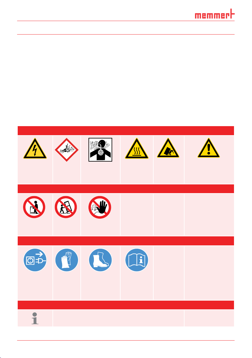
Safety regulations
Warning signs (warning of a danger)
Prohibition signs (forbidding an action)
Regulation signs (stipulating an action)
Other icons
Page 7
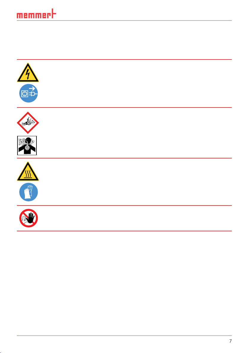
Safety regulations
After removing covers, live parts may be exposed. You may receive
Page 8
Safety regulations
Any other use is improper, and may result in hazards and damage.
Steriliser SF
Appliances IF/UF for use as medical device
Appliances IF/UF for use as medical device
Page 9
Safety regulations
You can find information on correcting malfunctions from page 29.
PLUS
ON
344.4
4444.
TEMP
Set
°C
°C
FLAP
40%
TIMER
hd
1002
End Sept.29 22 24
FAN
%0
%
100
ALARM
max
444.4°C
auto
+
/
-
0.0K
min
444.4°C
N
N
Manu
44.Sept
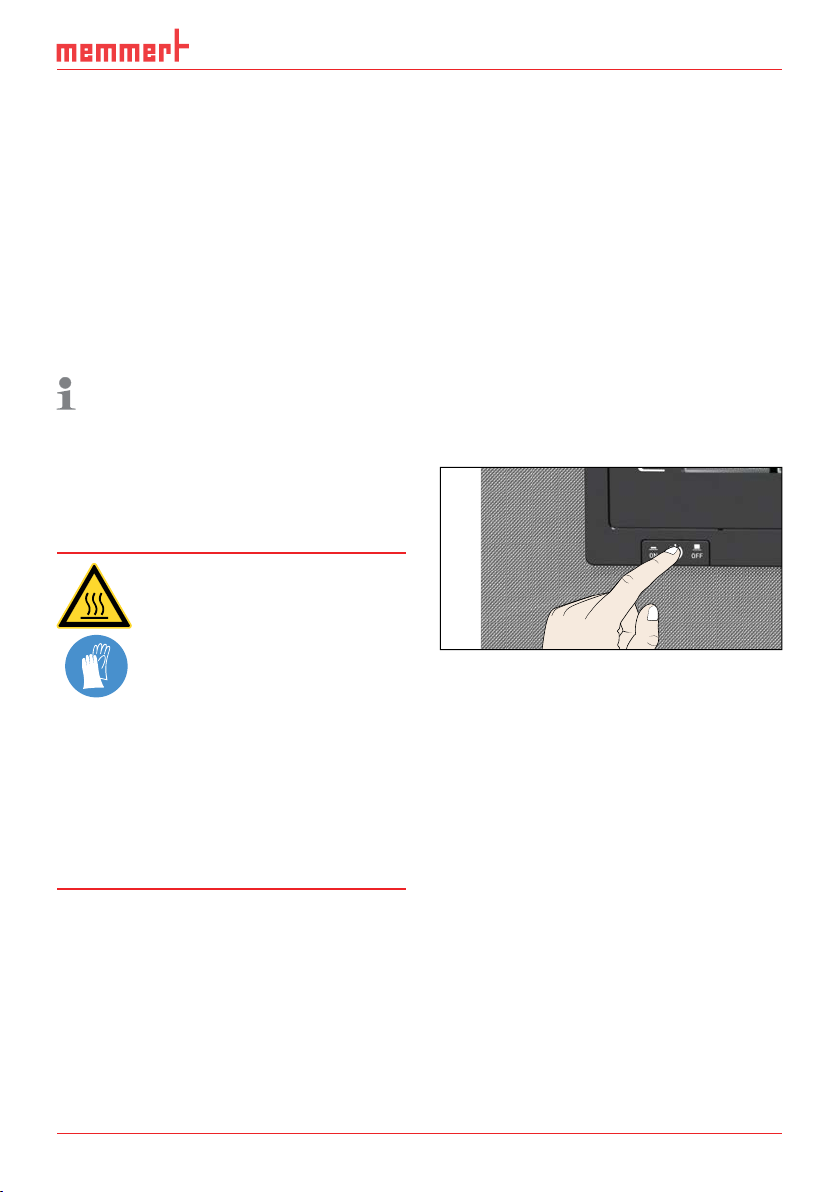
Switch off the appliance by pressing the On/
Page 10
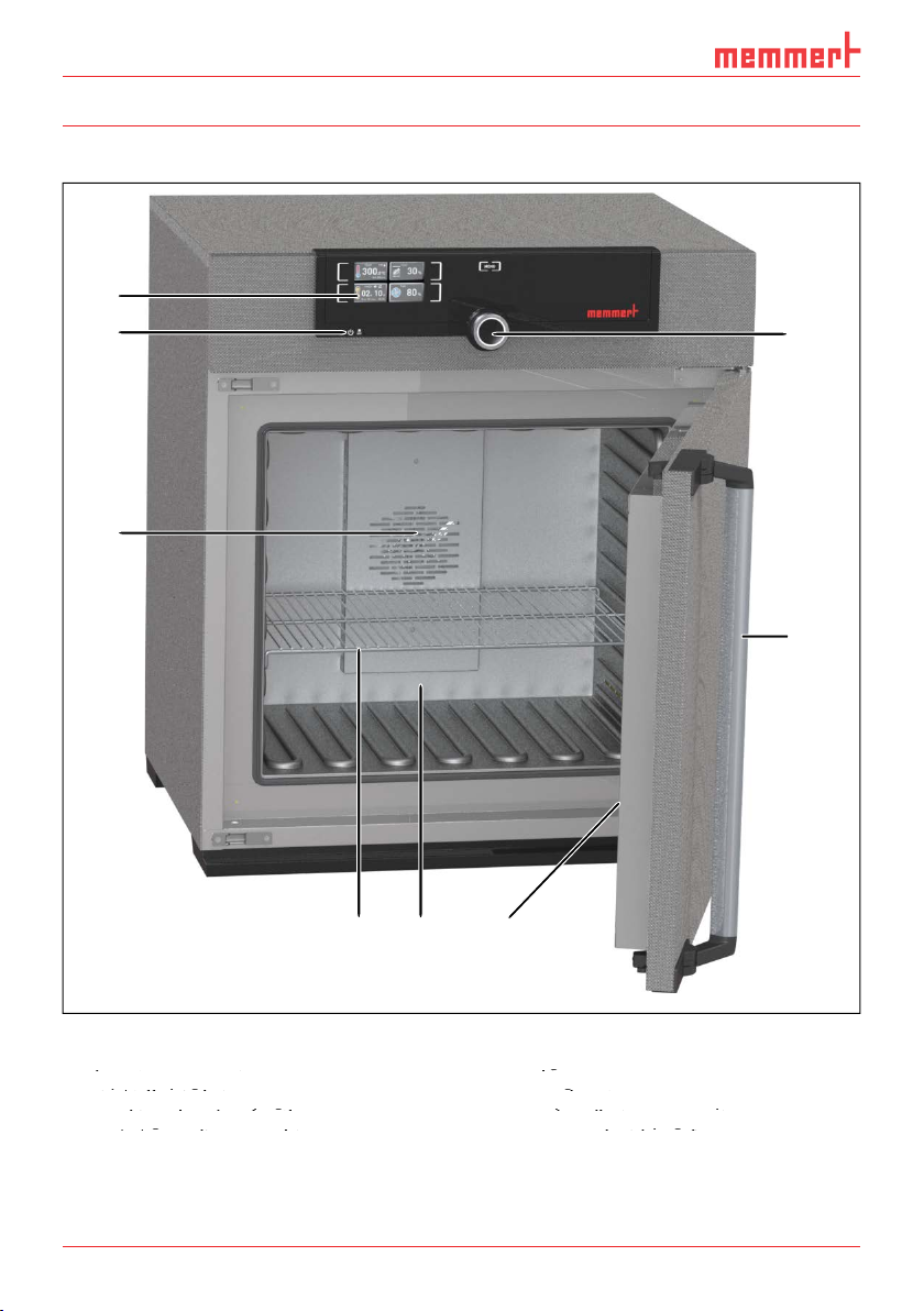
Setup and description
Construction
1
Construction
keys (see page 23)
3
Steel grid
5
Nameplate (covered, see page 12)
2
3
8
7
4
5 6
Page 11
Setup and description
Appliances of the UN, SN and
Appliance fuse: Fusible link 250 V/15 A quick-blow
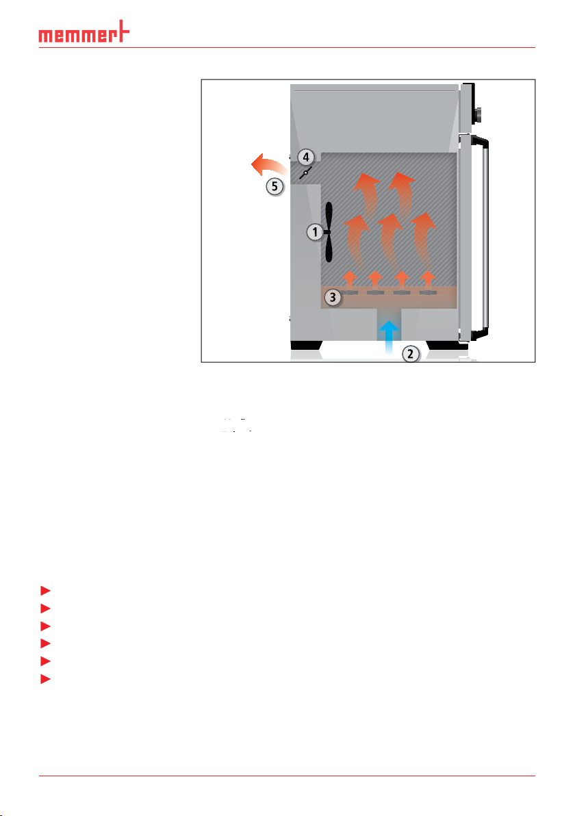
Function
2
3
Air flap
5
Page 12
Setup and description
of a maximum of 0.292 ohm at the point of transfer (service line). The
of a maximum of 0.292 ohm at the point of transfer (service line). The
AtmoCONTROL, the optional
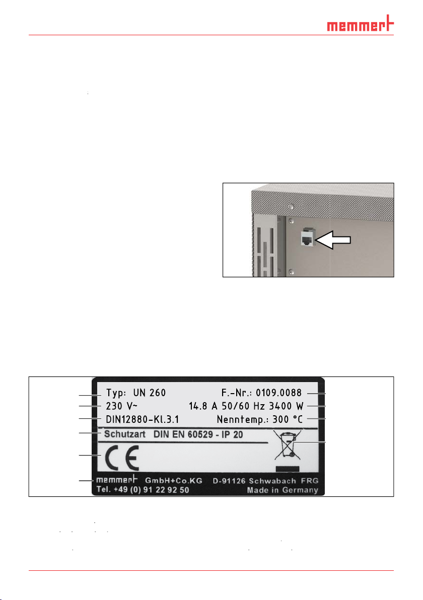
2.6 Designation ( nameplate)
Nameplate (example)
2
3
Applied standard
5
Address of manufacturer
Appliance number
Ethernet interface
The nameplate (Fig. 5) provides information about the appliance model
1
2
3
4
5
6
Typ: UN 260 F.-Nr.: 0109.0088
230 V
~
14.8 A 50/60 Hz 3400 W
DIN12880-Kl.3.1 Nenntemp.: 300 °C
10
9
8
7
Page 13
Setup and description
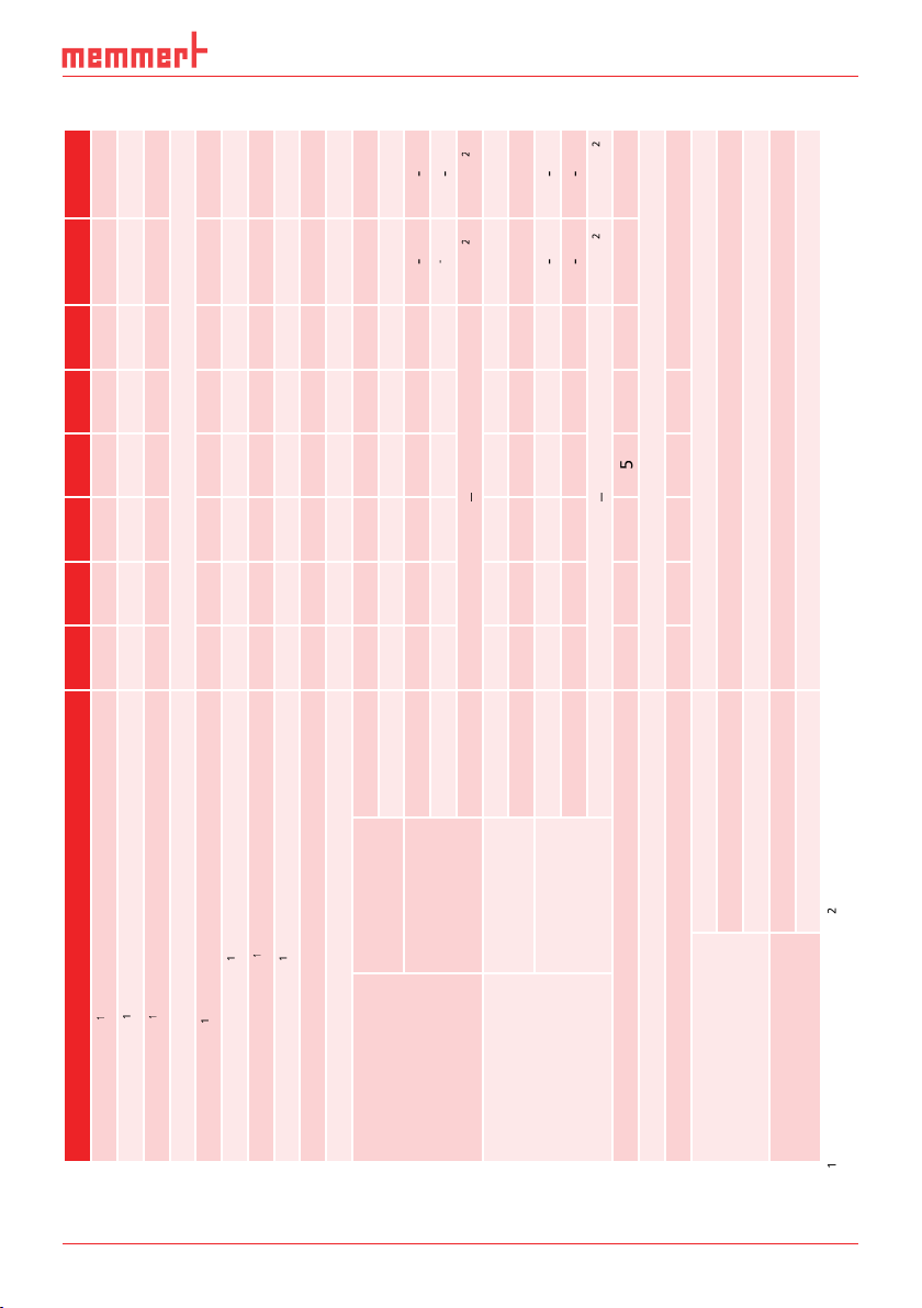
Appliance size 30 55 75 110 160 260 450 750
[mm]
[mm]
[mm]
[mm]
–
–
See Fig. 6 on page 14.
3 x 230 V without zero
Page 14
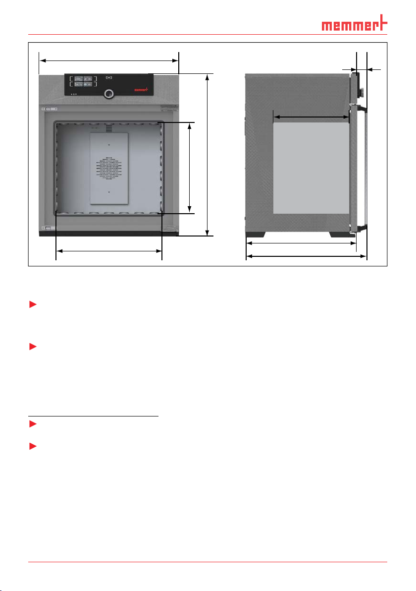
Setup and description
D
Applied directives and standards
C
E
B
56
A
G
F
Page 15
Setup and description
Ambient conditions
Ambient temperature
Altitude of installation
Optional
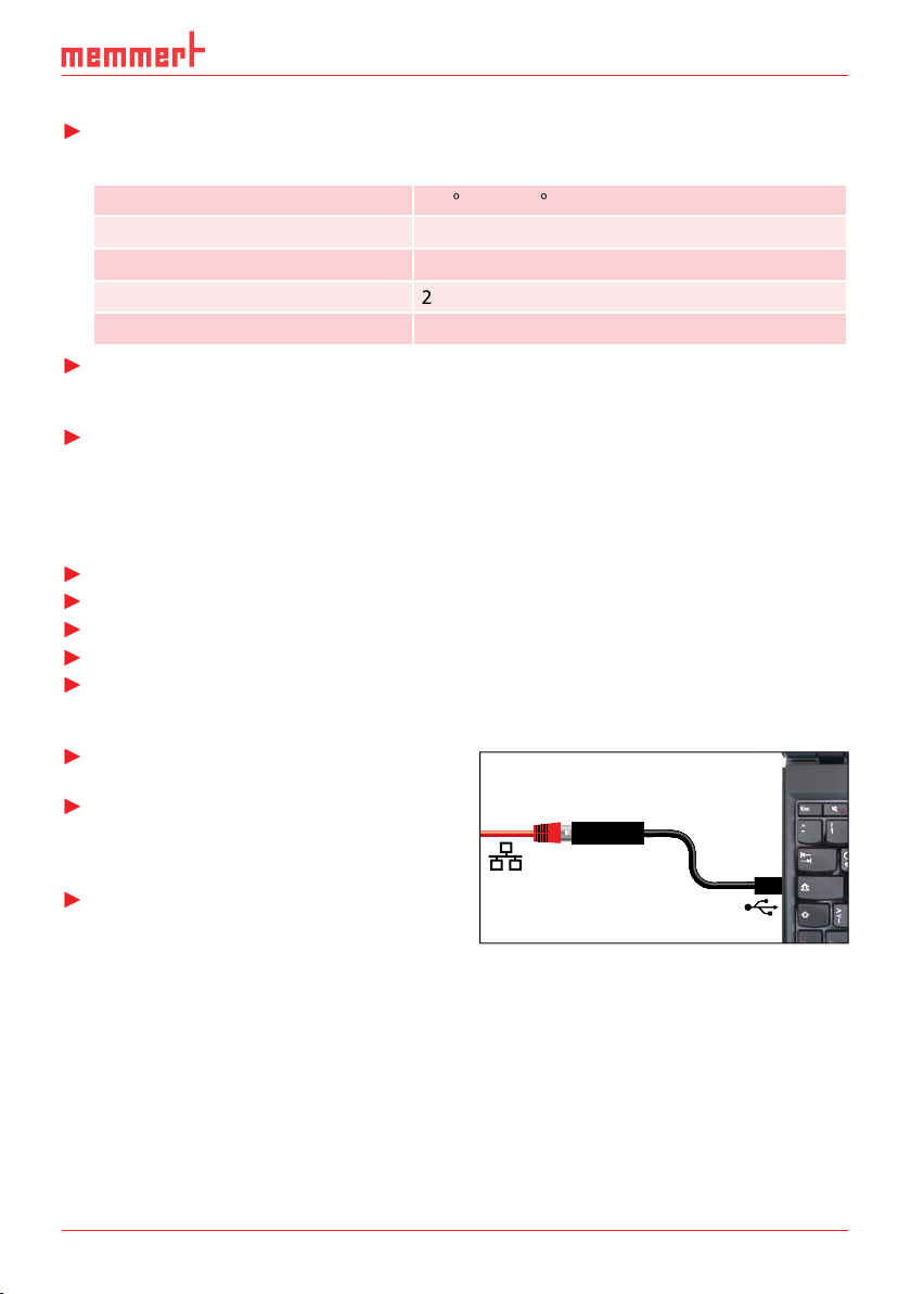
AtmoCONTROL software for reading out
Converter USB to Ethernet
Page 16

You may get your hands or feet squashed when transporting
30 55 75 110 160 260 450 750
Page 17

≥ 5 cm ≥ 5 cm ≥ 15 cm
Minimum clearance from walls and ceiling
≥ 20 cm
Page 18

Setting up Comments
Suitable for appliance size ...
30 55 75 110 160 260 450 750
Page 19
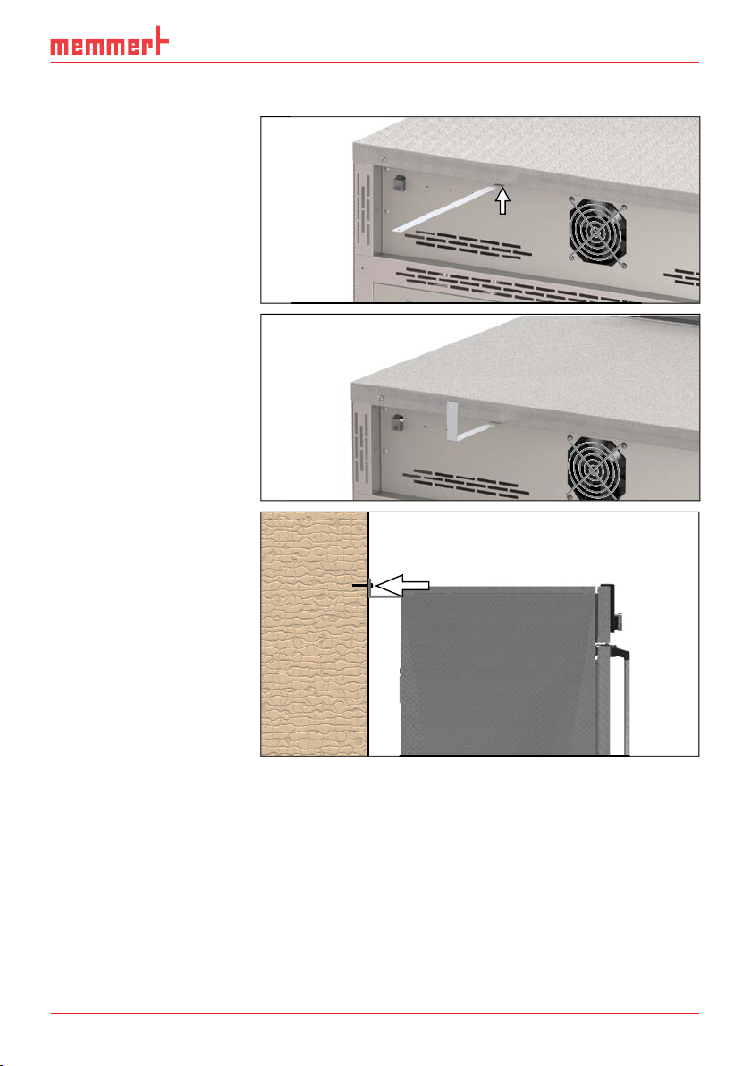
Tilt protection
Attach the appliance to a
As illustrated, fasten the
Page 20

230/115-V appliances:
230/115-V appliances:
Power connection
230/115 V
400 V CEE connection
PLUS
ON
344.4
4444.
TEMP
Set
°C
°C
FLAP
40%
TIMER
hd
1002
End Sept.29 22 24
FAN
%0
%
100
ALARM
max
444.4°C
auto
+
/
-
0.0K
min
444.4°C
N
N
Manu
44.Sept
Switch on
appliance
Page 21

Operation and control
A
Opening and closing the door
B
C
Page 22
Operation and control
(see page 37).
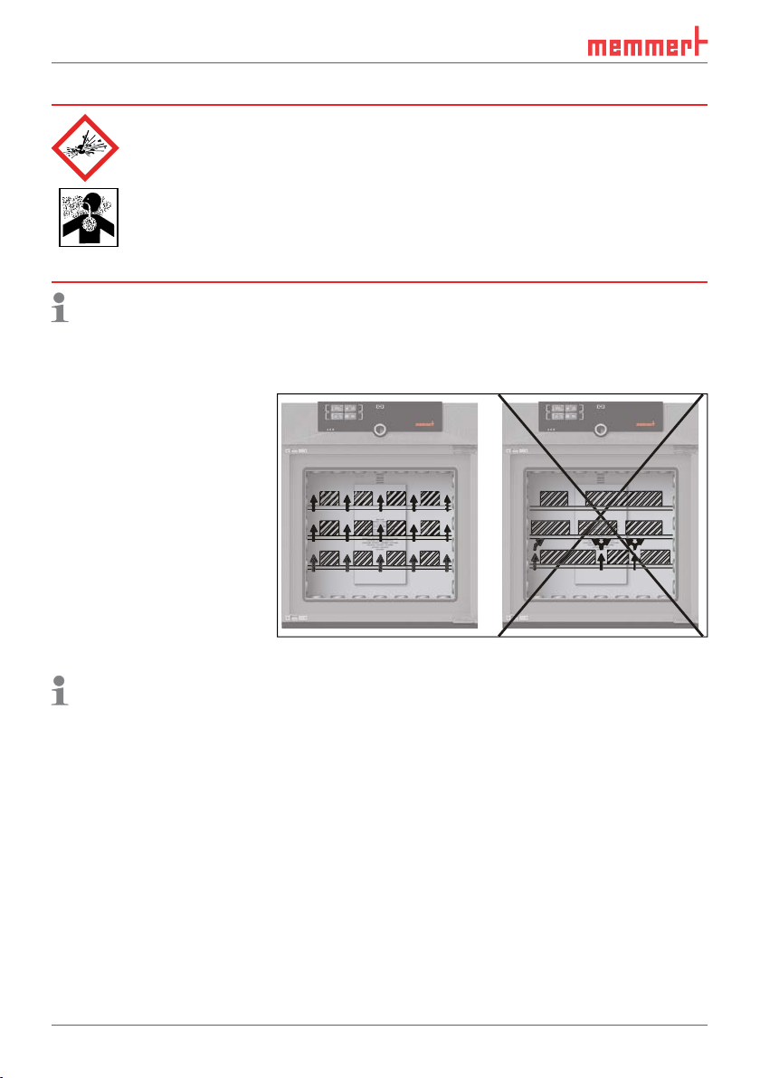
Correct placement of the
Page 23
Operation and control
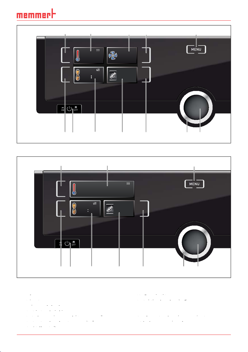
53 41 2
ControlCOCKPIT for UN/IN/SN appliances in operating mode
Activation key for temperature setpoint
adjustment
Activation key for temperature setpoint
Activation key for temperature setpoint
2
Setpoint and actual temperature display
adjustment
adjustment
3
Activation key for fan speed setting
5
Switch to menu mode (see page 31)
Activation key for fan speed setting
Activation key for fan speed setting
Activation key for timer setting
Switch to menu mode (see page 31)
Switch to menu mode (see page 31)
Air flap position display
Activation key for air flap position adjust-
Air flap position display
Air flap position display
ment
TEMP
180.4°C
Set 180
TIMER
TIMER
30m04h
44h:44m
End
13:30 23.11.
End 14:45
.4°C
FAN
FLAP
FLAP
0
40%
20%
%
11 126 7 8 9 10
1 2 5
TEMP
180.0 °C
Set 180.9°C
FLAP
TIMER
TIMER
30m04h
44h:44m
End
13:30 23.11.
End 14:45
FLAP
40%
6 7 8 9
10 11 12
Page 24
Operation and control
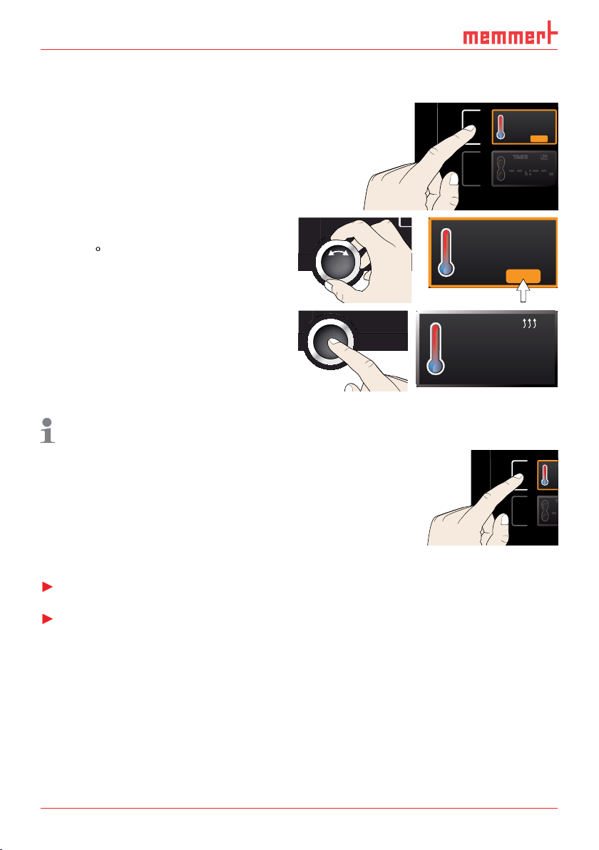
Activate the desired parameter (e.g. tem-
30.0
%rh
50.0
%CO2
MENU
30.0
%rh
50.0
%CO2
MENU
TEMP
%
100
ALARM
max
444.4°C
auto
+
/
-
0.0K
min
444.4°C
Manu
44.Sept
%
100
ALARM
max
444.4°C
auto
+
/
-
0.0K
min
444.4°C
Manu
44.Sept
Additional parameters (air flap position etc.) can be set accordingly.
30.0
%rh
50.0
%CO2
Programm 12
Fr 20.10.2010 20:31
min
000°C
max
000°C
.5°C100
MENU
30.0
%rh
50.0
%CO2
Programm 12
Fr 20.10.2010 20:31
min
000°C
max
000°C
MENU
22.4°C
TEMP
37.0°CSet
TEMP
22.4°C
180.0°CSet
TEMP
23.2°C
Set 180
22.4°C
37.0°CSet
.5°C100
.0°C
Page 25
Operation and control
Adjustment options
Adjustment options
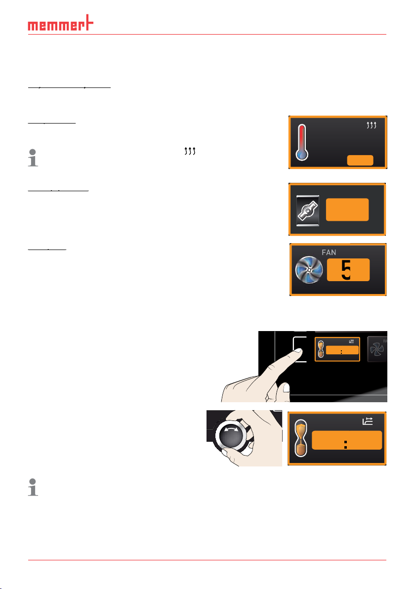
As described in chapter 5.4.2, you can set the following parameters after pressing the cor-
Adjustment range: model dependent (see nameplate and technical
symbol.
You can select °C or °F as the temperature unit displayed (see
TEMP
Air flap position
Air flap position
Adjustment range: 0 % (closed, recirculating operation) to 100 %
Adjustment range: 0 to 100 % in steps of 10%
30.0
%rh
50.0
%CO2
.5°C100
MENU
30.0
%rh
50.0
%CO2
MENU
%
100
ALARM
max
444.4°C
auto
+
/
-
0.0K
min
444.4°C
Manu
44.Sept
24.4°C
180.4 °CSet
FLAP
FAN
%40
50
TIMER
-
--h- m
9:00 23.11.
Ende
TIMER
04 mh 3
13:30 23.11.
End
0
%
Page 26
Operation and control
%
100
ALARM
max
444.4°C
auto
+
/
-
0.0K
min
444.4°C
Manu
44.Sept
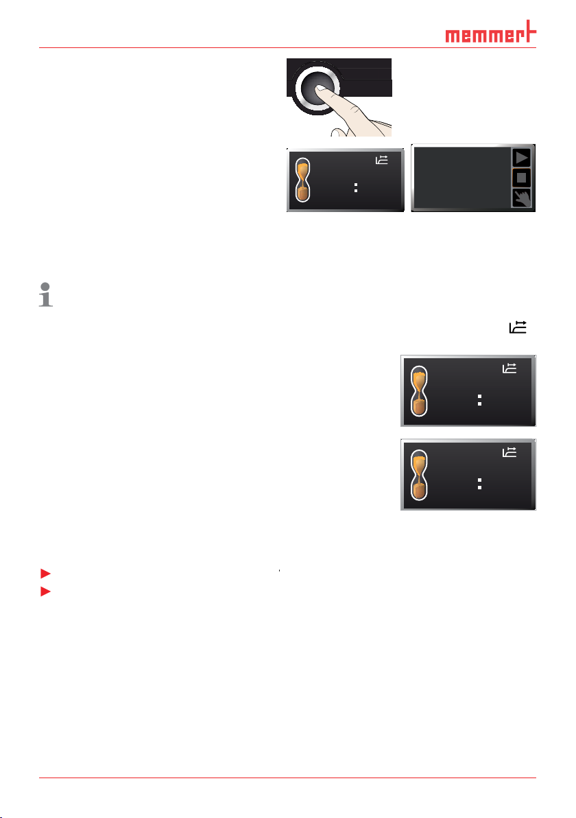
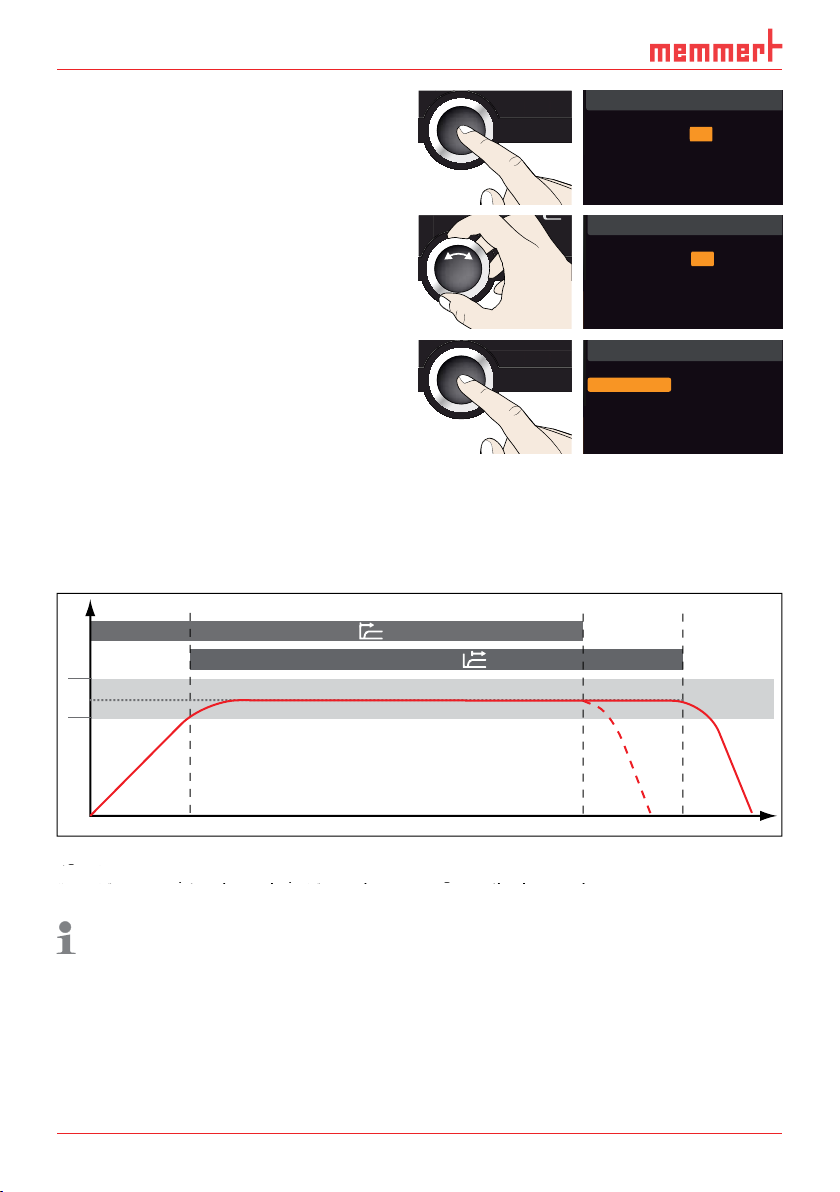
The status display
TIMER
5.4.2
– this determines if the timer should not start
Electronic temperature monitoring (
Ende
30m04h
13:30 23.11.
12.Sept.2012
Timer active
TIMER
End
TIMER
End
13:44
00m00h
13:30 23.11.
--m--h
9:00 23.11.
Page 27

Operation and control
°C
Schematic diagram of how the TWW temperature monitoring system works
t
Schematic diagram of how the TWB temperature monitoring works
Emergency operation
Setting Max Alarm
Set
temperature
Controller error
t
°C
heating switched off by TWB
Setting Max Alarm
Set
temperature
Controller error
Page 28
Operation and control
is shown (Fig. 18 ). The type
is shown (Fig. 18 ). The type
End14:45
Holz trocknen
aufheizen
09:12h
Fr 20.10.2010 20:31
min
000°C
ALARM
of °C
max
000°C
auto off
99K
+
0 12
%rh°C
GRAPH
off
ONON
344.4
4444.
TEMP
Set
°C
°C
FLAP
40%
TIMER
hd
1002
End Sept.29 22 24
FAN
%0
%
100
ALARM
max
444.4°C
auto
+
/
-
0.0K
min
444.4°C
Manu
44.Sept
LICHT
%
100
ALARM
max
190.0°C
5.0K
min
160.0°C
auto
+
-
Manueller Betrieb
12.Sept.2012
13:44
Ende
13:30 23.11.
TEMP
180.4°C
TEMP
Set 185
.0°C
344.4
444 4.
TEMP
Set
°C
°C
FLAP
40%
LÜFTER
%
0
23.2°C
TEMP
Set 180
.0°C
TEMP
TB Set 190.0 °C
195.4°C
PLUS
344.4
4444.
TEMP
Set
°C
°C
FLAP
40%
TIMER
hd
1002
End Sept.29 22 24
FAN
%0
%
100
ALARM
max
444.4°C
auto
+
/
-
0.0K
min
444.4°C
N
N
Manu
44.Sept
Switch off
appliance
TEMP
TEMP
195.4°C
TB Set 190.0 °C
23.2°C
180.4°C
Set 180
Set 185
TIMER
TIMER
30m04h
44h:44m
LÜFTER
0
FLAP
KLAPPE
40%
20%
%
ON
.0°C
.0°C
Page 29

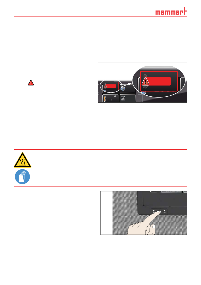
After removing covers, live parts may be exposed. You may receive
Description Cause Action See
/ overtemperature
are displayed
TEMP
195.4°C
TWW Set 190.0 °C
TEMP
195.4°C
TWB Set 190.0 °C
TEMP
230.4 °C
TB
Page 30
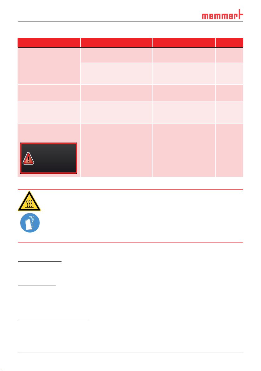
Error description Cause of errors Rectifying errors See
Appliance is in timer mode
Appliance is in "wrong"
key
Appliance error
Additionally, depending on the duration of the power loss, the
After power supply has been restored, operation is continued with the parameters set. The
After power supply has been restored, the timer always starts again.
Error 23
Pt100 Error
Contact
Service
Page 31

can make basic settings as well as adjust appliance parameters.
enter menu mode, press the MENU key.
USER ID
344.4
444 4.
TEMP
Set
°C
°C
FLAP
40%
TIMER
hd
1002
End Sept.29 22 24
FAN
%0
1 2 3 4 5
3
5
Setup activation key (basic appliance set-
Setup display (basic appliance settings)
Adjustment display
Setup display (basic appliance settings)
Setup display (basic appliance settings)
Adjustment activation key
Adjustment display
Adjustment display
%
100
ALARM
max
444.4°C
auto
+
/
-
0.0K
min
444.4°C
Manu
44.Sept
TIME
LANGUAGE
SIGNALTÖNE
SETUP
CALIB
6 7 8 9 10 11
Page 32

Activate the desired parameter (in this
LANGUAGE
OG
D
O
OCO
PROG
ZEIT UND DATUM
USER ID
PROTOCOL
LANGUAGE
PROGRAM
USER ID
PROTOCOL
SOUND
PLUS
344.4
4444.
TEMP
Set
°C
°C
FLAP
40%
TIMER
hd
1002
End Sept.29 22 24
FAN
%0
%
100
ALARM
max
444.4°C
auto
+
/
-
0.0K
min
444.4°C
N
N
Manu
44.Sept
%
100
ALARM
max
444.4°C
auto
+
/
-
0.0K
min
444.4°C
Manu
44.Sept
%
100
ALARM
max
444.4°C
auto
+
/
-
0.0K
min
444.4°C
Manu
44.Sept
SIGNALTÖNE
PROG
ZEIT UND DATUM
CALIB
USER ID
PROTOCOL
PROGRAM
TIME
USER ID
PROTOCOL
SOUND
PLUS
344.4
4444.
TEMP
Set
°C
°C
FLAP
40%
TIMER
hd
1002
End Sept.29 22 24
FAN
%0
%
100
ALARM
max
444.4°C
auto
+
/
-
0.0K
min
444.4°C
Manu
44.Sept
You can now
SETUP
PROGRAM
TIME
USER ID
PROTOCOL
PROGRAM
ER I
D
R
OTOCO
L
+30%
192.168.100.100
Alarm Temp
°C F
TWW TWB
Timer Mode
Setup
192.168.100.100
Subnet mask 255. 255.0.0
°C F
TWW TWB
Timer mode
Slide-in unit
Grid Shelf
%
100
ALARM
max
444.4°C
auto
+
/
-
0.0K
min
444.4°C
Manu
44.Sept
ENGLISH
DEUTSCH
FRANCAIS
ESPANOL
SIGNALTÖNE
TIME
SETUP
ON
CALIB
SPRACHE
ENGLISH
DEUTSCH
FRANCAIS
ESPANOL
SPRACHE
ENGLISH
DEUTSCH
FRANCAIS
ESPANOL
LANGUAGE
SETUP
IP address
Balance
IP Adresse
Unit
Einheit
Alarm temp
Page 33

All other settings can be made accordingly. The settings possible are described in the follow-
display, you can set the following parameters:
and
of the appliance's Ethernet interface (for connection to
of the temperature display (°C or °F, see page 34)
(see page 36)
Programm negnulletsniEllokotorPtäreG efliHnekcurD
network (schematic example)
Setup
Unit
IP adress 255.145.136.225
Subnet mask 255.255.0.0
°C F
1/2
AtmoCONTROL
INP 250 Test 01
180
.0°C
i
HPP 250 Labor
37
.0°C
i
44
.4%rh
-
+-+
Programmname
Editor
Simulation Protokoll
STAND BY
151
192.168.1.216
LAN 1: 192.168.1.233
LAN 2: 192.168.1.215
LAN 3: 192.168.1.241
Page 34

Activate the
display. The entry
is automatically highlighted.
PROGRAM
TIME
PROGRAM
D
O
OCO
Setup
Accept the selection by pressing the
%
100
ALARM
max
444.4°C
auto
+
/
-
0.0K
min
444.4°C
Manu
44.Sept
SETUP
%
100
ALARM
max
444.4°C
auto
+
/
-
0.0K
min
444.4°C
Manu
44.Sept
SETUP
Accept the selection by pressing the
%
100
ALARM
max
444.4°C
auto
+
/
-
0.0K
min
444.4°C
Manu
44.Sept
SETUP
After setting the last three digits, accept
%
100
ALARM
max
444.4°C
auto
+
/
-
0.0K
min
444.4°C
Manu
44.Sept
SETUP
Activate the
display and select
%
100
ALARM
max
444.4°C
auto
+
/
-
0.0K
min
444.4°C
Manu
44.Sept
SETUP
Accept the selection by pressing the
%
100
ALARM
max
444.4°C
auto
+
/
-
0.0K
min
444.4°C
Manu
44.Sept
SETUP
SETUP
IP address 192.168.100.100
Balance
Subnet mask 255. 255.0.0
IP Adresse
Unit
Einheit
Alarm temp
Alarm Temp
Timer mode
Timer Mode
Slide-in unit
+30%
192.168.100.100
°C F
°C F
TWW TWB
TWW TWB
Grid Shelf
IP address 192. 168.100.100
Subnet mask 255.255. 0.0
Unit
Alarm temp
°C F
TWW TWB
Timer mode
IP address 255. 168.100.100
Subnet mask 255.255. 0.0
Unit
Alarm temp
°C F
TWW TWB
Timer mode
IP address 255. 168.100.100
Subnet mask 255.255. 0.0
Unit
Alarm temp
°C F
TWW TWB
Timer mode
IP address 255. 145.136.225
Subnet mask 255.255. 0.0
Unit
Alarm temp
°C F
TWW TWB
Timer mode
IP address 255. 145.136.225
Subnet mask 255.255. 0.0
Unit
Alarm temp
°C °F
TWW TWB
Timer mode
IP address 255. 145.136.225
Subnet mask 255.255. 0.0
Unit
Alarm temp
°C °F
TWW TWB
Timer mode
Page 35

%
100
ALARM
max
444.4°C
auto
+
/
-
0.0K
min
444.4°C
Manu
44.Sept
SETUP
IP address 255. 145.136.225
%
100
ALARM
max
444.4°C
auto
+
/
-
0.0K
min
444.4°C
Manu
44.Sept
SETUP
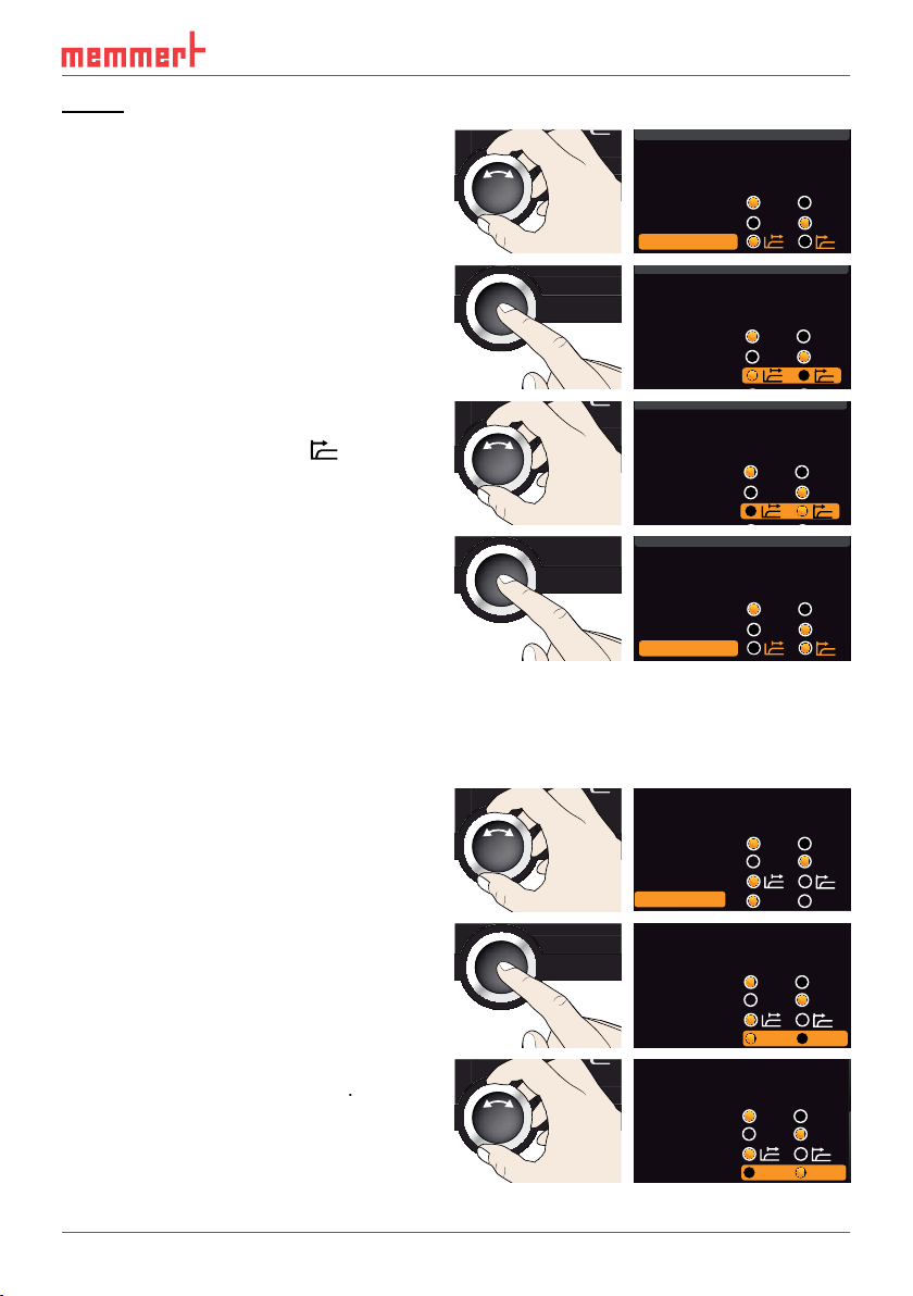
Alarm Temp and Max Alarm)
Activate the
display and select
with the turn control.
%
100
ALARM
max
444.4°C
auto
+
/
-
0.0K
min
444.4°C
Manu
44.Sept
SETUP
Accept the selection by pressing the
%
100
ALARM
max
444.4°C
auto
+
/
-
0.0K
min
444.4°C
Manu
44.Sept
SETUP
%
100
ALARM
max
444.4°C
auto
+
/
-
0.0K
min
444.4°C
Manu
44.Sept
SETUP
%
100
ALARM
max
444.4°C
auto
+
/
-
0.0K
min
444.4°C
Manu
44.Sept
SETUP
S
with the turn control.
%
100
ALARM
max
444.4°C
auto
+
/
-
0.0K
min
444.4°C
Manu
44.Sept
Subnet mask 255.255. 0.0
Unit
Alarm temp
°C °F
TWW TWB
Timer mode
IP address 255. 145.136.225
Subnet mask 255.255. 0.0
Unit
Alarm temp
°C °F
TWW TWB
Timer mode
IP address 255.145.136. 225
Subnet mask 255.255. 0.0
Unit
Alarm temp
°C F
TWW TWB
Timer mode
IP address 255.145.136. 225
Subnet mask 255.255. 0.0
Unit
Alarm temp
°C F
TWW TWB
Timer mode
IP address 255.145.136. 225
Subnet mask 255.255. 0.0
Unit
Alarm temp
°C F
TWW TWB
Timer mode
IP address 255.145.136. 225
Subnet mask 255.255. 0.0
Unit
Alarm temp
°C F
TWW TWB
Timer mode
2/2
Max Alarm
190 °C
SETUP
Page 36
Accept the selection by pressing the
%
100
ALARM
max
444.4°C
auto
+
/
-
0.0K
min
444.4°C
Manu
44.Sept
2/2
%
100
ALARM
max
444.4°C
auto
+
/
-
0.0K
min
444.4°C
Manu
44.Sept
%
100
ALARM
max
444.4°C
auto
+
/
-
0.0K
min
444.4°C
Manu
44.Sept
t
Timer Mode
A Timer independent of setpoint: Timer starts right after activation
Max Alarm
SETUP
190 °C
A
°C/°F
6 K
2/2
SETUP
Max Alarm
160 °C
SETUP
2/2
Max Alarm
t
Timer
B
t
Timer
160 °C
Page 37
Setting
Setting
Activate the
display and select
%
100
ALARM
max
444.4°C
auto
+
/
-
0.0K
min
444.4°C
Manu
44.Sept
SETUP
IP address 255. 145.136.225
Accept the selection by pressing the
%
100
ALARM
max
444.4°C
auto
+
/
-
0.0K
min
444.4°C
Manu
44.Sept
SETUP
).
%
100
ALARM
max
444.4°C
auto
+
/
-
0.0K
min
444.4°C
Manu
44.Sept
SETUP
%
100
ALARM
max
444.4°C
auto
+
/
-
0.0K
min
444.4°C
Manu
44.Sept
SETUP
Activate the
display and select
with the turn control.
%
100
ALARM
max
444.4°C
auto
+
/
-
0.0K
min
444.4°C
Manu
44.Sept
SETUP
Accept the selection by pressing the con-
%
100
ALARM
max
444.4°C
auto
+
/
-
0.0K
min
444.4°C
Manu
44.Sept
SETUP
%
100
ALARM
max
444.4°C
auto
+
/
-
0.0K
min
444.4°C
Manu
44.Sept
SETUP
Subnet mask 255.255. 0.0
Unit
Alarm temp
°C F
TWW TWB
Timer mode
IP address 255. 145.136.225
Subnet mask 255.255. 0.0
Unit
Alarm temp
°C F
TWW TWB
Timer mode
IP address 255. 145.136.225
Subnet mask 255.255. 0.0
Unit
Alarm temp
°C F
TWW TWB
Timer mode
IP address 255. 145.136.225
Subnet mask 255.255. 0.0
Unit
Alarm temp
°C F
TWW TWB
Timer mode
IP adress 255.145.136.225
Subnet mask 255.255. 0.0
Unit
Alarm temp
°C °F
TWW TWB
Timer mode
Slide-in unit
Grid Shelf
IP adress 255.145.136.225
Subnet mask 255.255. 0.0
Unit
Alarm temp
°C °F
TWW TWB
Timer mode
Slide-in unit
Grid Shelf
IP adress 255.145.136.225
Subnet mask 255.255. 0.0
Unit
Alarm temp
°C °F
TWW TWB
Timer mode
Slide-in unit
Grid Shelf
Page 38

%
100
ALARM
max
444.4°C
auto
+
/
-
0.0K
min
444.4°C
Manu
44.Sept
SETUP
display, you can set the date and time, time zone and daylight savings.
Activate the time setting To do so, press
display. The display is enlarged
Date
– e.g. the time zone: Turn the turn
%
100
ALARM
max
444.4°C
auto
+
/
-
0.0K
min
444.4°C
Manu
44.Sept
TIME
Accept the selection by pressing the
%
100
ALARM
max
444.4°C
auto
+
/
-
0.0K
min
444.4°C
Manu
44.Sept
TIME
%
100
ALARM
max
444.4°C
auto
+
/
-
0.0K
min
444.4°C
Manu
44.Sept
TIME
%
100
ALARM
max
444.4°C
auto
+
/
-
0.0K
min
444.4°C
Manu
44.Sept
TIME
Time
Time zone
Daylight savings
Date and time
12. 05. 2012
12:00
GMT +1
IP adress 255.145.136.225
Subnet mask 255.255. 0.0
Unit
Alarm temp
°C °F
TWW TWB
Timer mode
Slide-in unit
Grid Shelf
Date
Time
Time zone
12.05 .2012
12:00
GMT +1
Daylight savings
Date 12
Time
Time zone
.05. 2012
12:00
GMT +1
Daylight savings
Date 27
Time
Time zone
.05. 2012
12:00
GMT +1
Daylight savings
Date 27 05
Time
Time zone
. . 2012
12:00
GMT +1
Daylight savings
Page 39

Accordingly, you can also set:
Year
-11 -10 -9 -8 -7 -6 -5 -4 -3 -2 -1 0 +1 +2 +3 +4 +5 +6 +7 +8 +9 +10 +11
+12 -12-11
-11 -10 -9 -8 -7 -6 -5 -4 -3 -2 -1 0 +1 +2 +3 +4 +5 +6 +7 +8 +9 +10 +11
+12 -12-11
Time zones
Page 40

CAL 1
Schematic example of temperature adjustment
Activate the adjustment setting. To do
display. The display
PROGRAM
TIME
USER ID
PROTOCOL
PROGRAM
ER I
D
R
O
T
OCO
L
%
100
ALARM
max
444.4°C
auto
+
/
-
0.0K
min
444.4°C
Manu
44.Sept
JUSTIEREN
%
100
ALARM
max
444.4°C
auto
+
/
-
0.0K
min
444.4°C
Manu
44.Sept
JUSTIEREN
%
100
ALARM
max
444.4°C
auto
+
/
-
0.0K
min
444.4°C
Manu
44.Sept
JUSTIEREN
+0,5 K
CAL 3
-0,8 K
CAL 2
+2,6 K
factory calibration
0°C
40°C
120°C
Temperatur
Temperature
Last updated 12.10.2012 12:00:00
letzte Justierung 12.10.2012 12:00
180°C
JUSTIEREN
Calibration
Cal1
°C -0,2
40.0
C K0,2-
Cal1
40.0
Cal2 100.0 °C +0,1K
C K0,1+
Cal2
100.0
Cal3 180.0 °C -0,2 K
C K0,2-
180.0
Cal3
K
Temperature
Temperature
Temperature
Cal1
Cal2
100.0
Cal3
180.0
Cal1
Cal2
120.0
180.0
Cal3
Cal1
Cal2
120.0 0,1+
Cal3
180.0
40.0
40.0
40.0
C K0,2-
C K0,1+
C K0,2-
C K0,2-
C K0,1+
C K0,2-
C K0,2-
C K
C K
0,2-
Page 41

%
100
ALARM
max
444.4°C
auto
+
/
-
0.0K
min
444.4°C
Manu
44.Sept
Calibration
TEMP
%
100
ALARM
max
444.4°C
auto
+
/
-
0.0K
min
444.4°C
Manu
44.Sept
JUSTIEREN
After the calibration procedure, the
°C
Temperature
Cal1
40.0
Cal2
120.0 0,0
Cal3
180.0
TEMP
21.4°C
C K0,2-
C K
C K
120.0 °CSet
0,2-
120.0°C
Set 120
.0°C
TEMP
120.0°C
Set 120
.0°C
Temperature
122.6 °C
C K0,2-
Cal1
40.0
C K
Cal2
120.0 2,6+
C K
Cal3
180.0
120.0 °C
0,2-
Page 42

Sterilisers SF/SN
According to WHO: 180 °C with a minimum hold time of 30 min
According to the European Pharmacopoeia: 160 °C with a minimum hold time of 120 min
destroy
Page 43

Maintenance and service
Maintenance and service
After removing covers, live parts may be exposed. You may
Page 44

Storage and disposal
Storage
August 13
Page 45

Index
A
Accessories 15
Activation key 24
Adjustment 39
Air flap position 25
Air supply 11
Alarm 35
Alarm temperature 35
Ambient conditions 14
Ambient temperature 15
Appliance error 30
AtmoCONTROL 3
Page 46

Page 47

Page 48

Universal ovens
Incubators
Sterilisers
24.05.2013
D24022 // englisch
Memmert GmbH + Co. KG
Willi-Memmert-Straße 90-96 | D-91186 Büchenbach
Tel. +49 9122 925-0 | Fax +49 9122 14585
E-Mail: sales@memmert.com
facebook.com/memmert.family
Die Experten-Plattform: www.atmosafe.net
 Loading...