

Page 1

www.memmert.com | www.atmosafe.net
UN UF
IN IF
SN SF
100% ATMOSAFE. MADE IN GERMANY.
OPERATING INSTRUCTIONS
Page 2

Willi-Memmert-Straße 90–96
When contacting customer service, always quote the product serial number on the nameplate
).
Willi-Memmert-Str. 90-96
We reserve the right to make changes
Page 3

About this manual
About this manual
This manual describes the setup, function, transport, operation and maintenance of universal
there is something you do not understand, or certain information is missing, ask your superior
Versions
The appliances are available in different configurations and sizes. If specific equipment fea-
tures or functions are available only for certain configurations, this is indicated at the relevant
from the actual appearance. Function and operation are identical.
AtmoCONTROL, observe the separate
This instruction manual belongs with the appliance and should always be stored where
whereabouts of this instruction manual. We recommend that it is always stored in a protected
You will find the current version of our operating manual as pdf file if you go to
www.memmert.com/de/service/downloads/bedienungsanleitung/.
Page 4

......................................................................................................................
...............................................................................................
............................................................................................
....................................................................................................................
...........................................................................................................
..............................................................................................................
............................................................................................................................
.........................................................................................................................
..........................................................................................................................
......................................................................................................
..............................................................................................................
.................................................................................................
......................................................................................................................
Page 5

..............................................................................................................
.......................................................................................................
....................................................................................................
............................................................................................................
..............................................................................................................
...........................................................................................................
..................................................................................................
............................................................................
.......................................................................................................................
..........................................
................................................
......................................................................................................................
.......................
..............................................................................................................................
....................................................................................................................
......................................................................................................................
.........................................................
.............................................................................................................................
........................................................................
..................................................................................................................
..............................................................................................................
............................................................................................................
Page 6
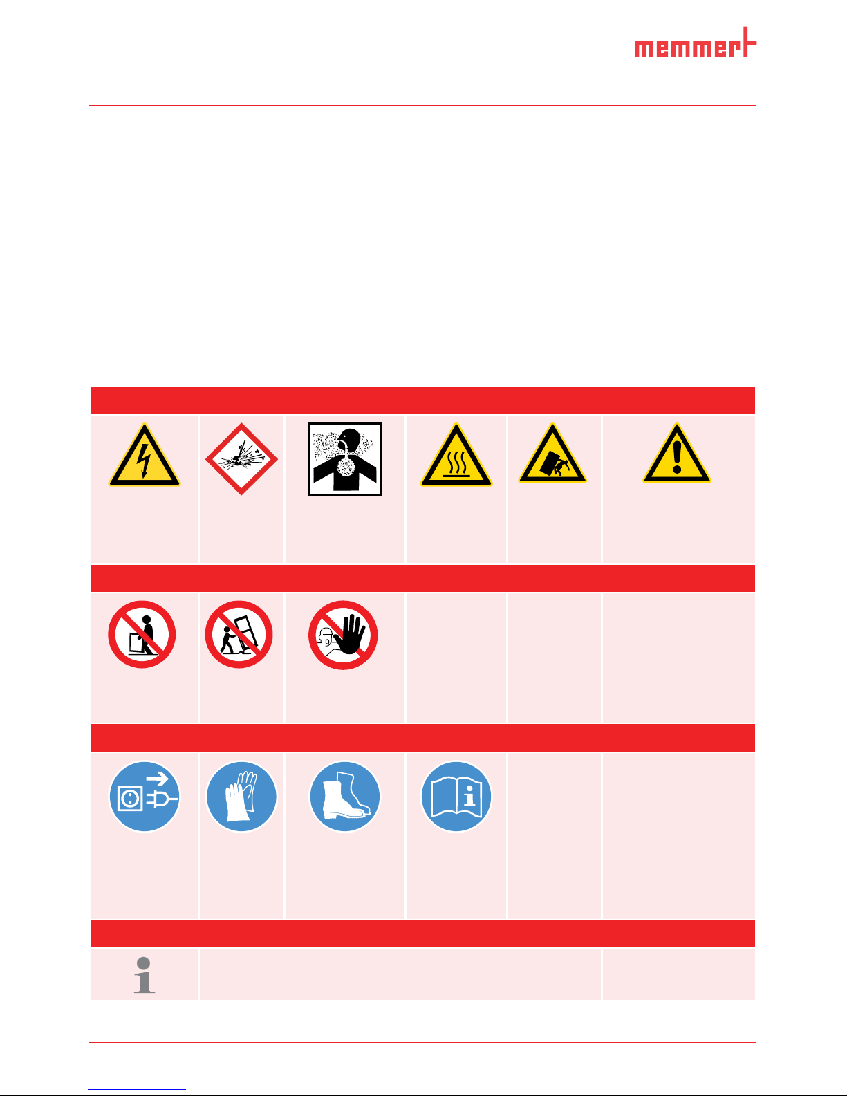
Safety regulations
Terms and signs used
you of possible dangers or to give you hints that are important in avoiding injury or damage.
Terms used
Warning signs (warning of a danger)
vapours
toppling
ting instructions
Prohibition signs (forbidding an action)
tilt
Regulation signs (stipulating an action)
the mains
Wear
Wear safety
Other icons
Page 7

Safety regulations
The appliances described in this manual are technically sophisticated, manufactured using
Warning!
After removing covers, live parts may be exposed. You may receive
the electrical equipment of the appliances.
Warning!
When loading the appliance with an unsuitable load, poisonous
the appliance to explode, and persons could be severely injured or
Warning!
To do so, pull the handle bar until the door springs open into its
ventilating position (see page 21).
Warning!
The appliance may only be operated and maintained by persons who are of legal age
Page 8

Safety regulations
The owner of the appliance
);
work is carried out properly (see page 43);
through corresponding instructions and inspections;
This appliance is exclusively intended for heating up non-explosive substances and objects.
Any other use is improper, and may result in hazards and damage.
The appliance is not
which cannot form any toxic or explosive vapours at the set temperature and which cannot
The appliance may not be used for drying, vaporising and branding paints or similar materials
the solvents of which could form an explosive mixture when combined with air. If there is
the direct vicinity of the appliance.
Steriliser SF
The appliance’s intended use is the sterilisation of medical material through dry heated air at
Appliances IF/UF for use as medical device
Appliances IF/UF for use as medical device
warming of non-sterile cloths and covers.
Page 9
Safety regulations
validity and the appliance must no longer be operated.
The manufacturer is not liable for any damage, danger or injuries that result from
The appliance may only be used in a flawless condition. If you as the operator notice
You can find information on correcting malfunctions from page 29.
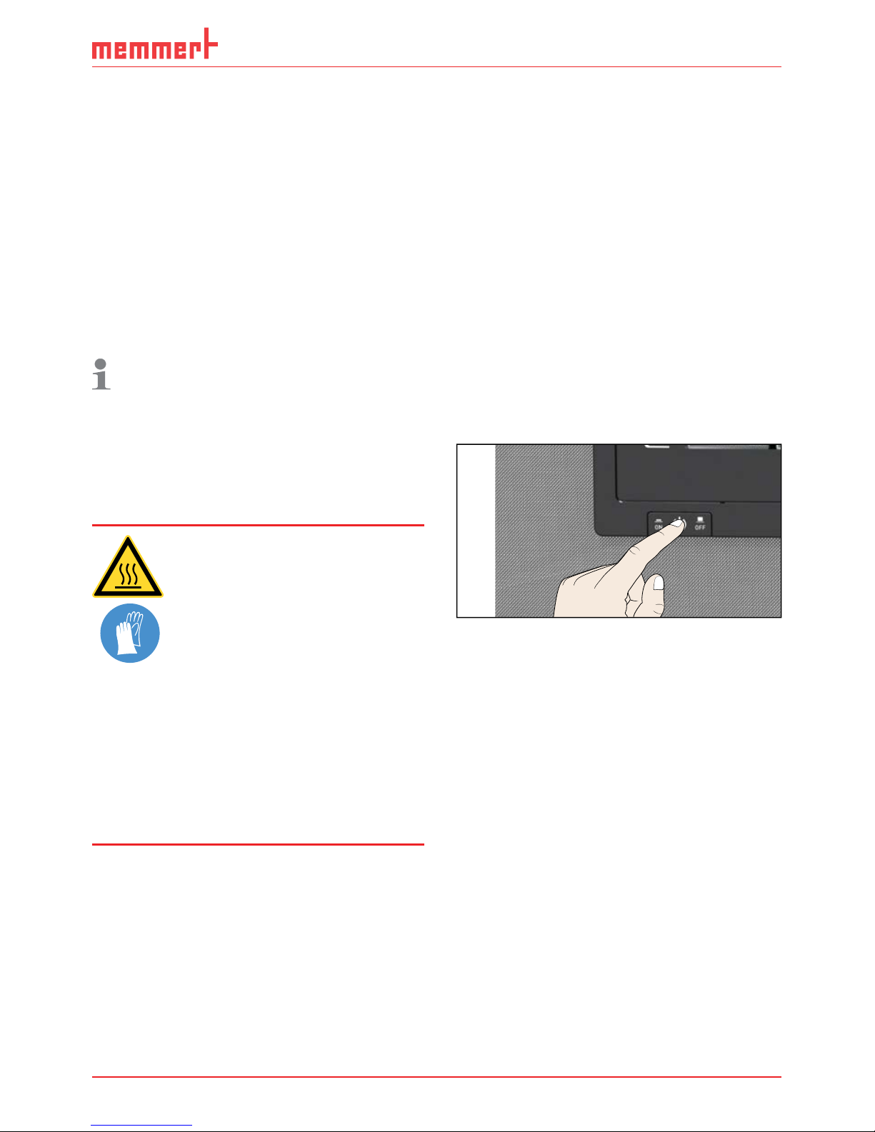
Warning!
Touching these surfaces can
the handle bar until the
ventilating position (see
PLUS
ON
344.4
444 4.
TEMP
Set
°C
°C
FLAP
40%
TIMER
hd
1002
End Sept.29 22 24
FAN
%0
%
100
ALARM
max
444.4°C
auto
+
/
-
0.0K
min
444.4°C
ONN
Manu
44.Sept
Fig. 1
Switch off the appliance by pressing the On/
Page 10

Setup and description
Construction
1
2
3
4
7
8
5 6
Fig. 2
Construction
keys (see page 23)
3
Steel grid
5
Nameplate (covered, see page 12)
Door handle (see page 21)
Nameplate (covered, see page 12)
Nameplate (covered, see page 12)
8
Page 11

Setup and description
Appliances of the UN, SN and
working chamber rear panel
the air flow and provides
fan ventilated appliances,
the working chamber, the
for the interior, stainless steel (Mat.No. 1.4301 – ASTM 304) is used, which stands out through
The chamber load for the appliance must be carefully checked for chemical compatibility with
the materials mentioned. A material resistance table can be requested from the manufacturer.
Appliance fuse: Fusible link 250 V/15 A quick-blow
The temperature controller is protected with a miniature fuse 100 mA (200 mA at 115 V)
Fig. 3
Function
Fan
2
Fresh air
3
Pre-heating chamber
4
Air flap
Pre-heating chamber
Pre-heating chamber
5
Exhaust air
Air flap
Air flap
Page 12
Setup and description
This appliance is intended for operation on an electrical power system with a system
of a maximum of 0.292 ohm at the point of transfer (service line). The
of a maximum of 0.292 ohm at the point of transfer (service line). The
the system impedance is.
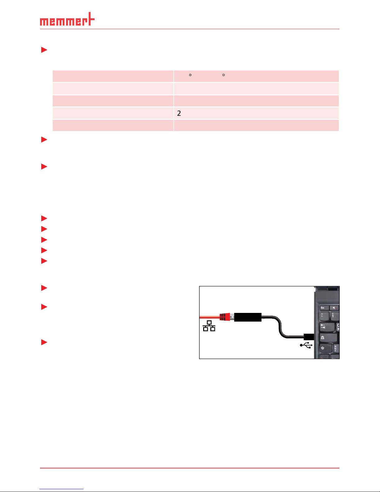
The Ethernet interface is intended for appliances which meet the requirements of IEC 60950-1.
Via Ethernet interface, the appliance can be
AtmoCONTROL, the optional
With an optional USB to Ethernet converter,
the appliance can be directly connected to a
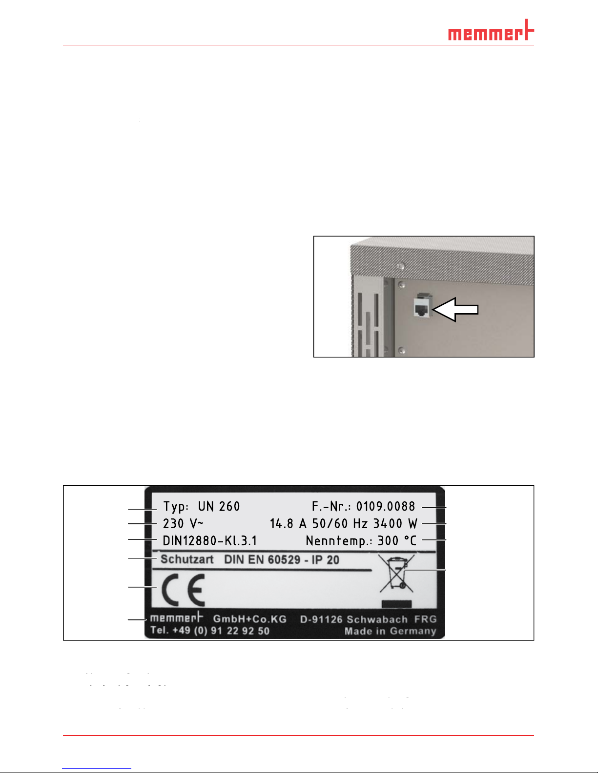
2.6 Designation ( nameplate)
The nameplate (Fig. 5) provides information about the appliance model
technical data. It is attached to the front of the appliance, on the right side under the door
Typ: UN 260 F.-Nr.: 0109.0088
230 V
~
14.8 A 50/60 Hz 3400 W
DIN12880-Kl.3.1 Nenntemp.: 300 °C
1
2
3
4
5
6
10
8
9
7
Fig. 5
Nameplate (example)
2
3
Applied standard
4
Protection type
5
Address of manufacturer
Disposal note
8
Appliance number
Fig. 4
Ethernet interface
Page 13

Setup and description
Technical data
Appliance size 30 55 75 110 160 260 450 750
[mm]
[mm]
[mm]
[mm]
–
–
See Fig. 6 on page 14.
3 x 230 V without zero
Page 14

Setup and description
D
A
G
F
C
56
E
B
Fig. 6
Dimensions (see table on page 13)
Applied directives and standards
the member states on electromagnetic compatibility). Fulfilled standards:
the member states on electromagnetic compatibility). Standards complied with:
Page 15
Setup and description
Ambient conditions
The appliance may only be used in enclosed rooms and under the following ambient
Ambient temperature
Altitude of installation
The appliance may not be used in areas where there is a risk of explosion. The ambient air
to sedimentation in the interior and, as a consequence, could result in short circuits or
Tilt protection
The operating instructions at hand
Optional
AtmoCONTROL software for reading out
Fig. 7
Converter USB to Ethernet
Page 16

transport and
Warning!
You may get your hands or feet squashed when transporting
Warning!
yourself if you try to lift it. To
30 55 75 110 160 260 450 750
Warning!
The appliance could fall over and seriously injure you. Never tilt the
The appliance is packed in cardboard and is delivered on a wooden palette.
Transport
The appliance can be transported in three ways:
With a
forklift truck; move the forks of the truck entirely under the pallet
To avoid damage, do not unpack the appliance until you reach the installation site.
transport damage
Page 17

Warning!
with the tilt protection (see page 19). If this cannot be done due
to space problems, do not operate the appliance and do not open
the door. Contact the Memmert service team (see page 2).
The
The distance between the wall and the rear of the appliance must be at least 15 cm. The
the appliance must be guaranteed at all times.
≥ 5 cm ≥ 5 cm ≥ 15 cm
≥ 20 cm
Fig. 8
Minimum clearance from walls and ceiling
Page 18

Setting up Comments
Suitable for appliance size ...
30 55 75 110 160 260 450 750
Table
two appliances
Wall
fastening material is
the assembly
with/without
frame
feet
Page 19

Tilt protection
Attach the appliance to a
wall with the tilt protection.
The tilt protection is included
As illustrated, fasten the
tilt protection to the rear
tion upwards by 90 ° in
the desired distance to
the wall (consider the
wall, see Fig. 8).
tion to a suitable wall.
Page 20

The first time the appliance is operated, it must not be left unattended until it has reached
the steady state.
VDE 0100 with residual current circuit breaker). Observe the connection and power ratings
230/115-V appliances:
230/115-V appliances:
400V appliances:
400V appliances:
The power cable is permanently installed. Connect the
will be prompted to set the operating language, date
Fig. 9
Power connection
230/115 V
Fig. 9
Fig. 9
Fig. 10
400 V CEE connection
PLUS
ON
344.4
444 4.
TEMP
Set
°C
°C
FLAP
40%
TIMER
hd
1002
End Sept.29 22 24
FAN
%0
%
100
ALARM
max
444.4°C
auto
+
/
-
0.0K
min
444.4°C
ONN
Manu
44.Sept
Fig. 11
Switch on
appliance
Page 21

Operation and control
When loading and operating
The appliance may only be operated by persons who are of legal age and have been instruct-
training may only work with the appliance under the continuous supervision of an experi-
To open the door, pull the handle bar to the side (to the left or to the right, depending on
the door variation, see Fig. 12, A). The door opens slightly, so that the heat can be vented
with the door ajar in case of high temperature inside the chamber. The door can then be
To close the door, push the handle bar back (C).
A
C
B
Fig. 12
Opening and closing the door
Warning!
Page 22

Operation and control
Warning!
When loading the appliance with an unsuitable load, poisonous
the appliance to explode, and persons could be severely injured or
the composition of materials, they must not be loaded into the appli-
the chamber load for chemical compatibility with the materials of the appliance
The chamber must not be
working chamber is guaran-
teed. Do not place any
touching the side walls or
working chamber (Fig. 13 , see
To achieve the correct heating capacity, the type of slide-in unit used – Grid or Shelf –
(see page 37).
Fig. 13
Correct placement of the
chamber load
Page 23

Operation and control
TIMER
End 14:45
44h:44m
180.4°C
TEMP
Set 180
.4°C
20%
FLAP
FAN
%
0
FLAP
40%
53 41 2
11 126 7 8 9 10
TIMER
30m04h
End
13:30 23.11.
Fig. 14
180.0 °C
Set 180.9°C
TEMP
TIMER
End 14:45
44h:44m
FLAP
FLAP
40%
1 2 5
10 11 12
TIMER
30m04h
End
13:30 23.11.
6 7 8 9
Fig. 15
ControlCOCKPIT for UN/IN/SN appliances in operating mode
Activation key for temperature setpoint
adjustment
Activation key for temperature setpoint
Activation key for temperature setpoint
2
Setpoint and actual temperature display
adjustment
adjustment
3
Fan speed display
Setpoint and actual temperature display
Setpoint and actual temperature display
4
Activation key for fan speed setting
Fan speed display
Fan speed display
5
Switch to menu mode (see page 31)
Activation key for fan speed setting
Activation key for fan speed setting
Activation key for timer setting
Switch to menu mode (see page 31)
Switch to menu mode (see page 31)
8
Air flap position display
Activation key for air flap position adjust-
Air flap position display
Air flap position display
ment
with the turn control)
Page 24

Operation and control
Activate the desired parameter (e.g. tem-
the respective display. The activated dis-
30.0
%rh
50.0
%CO2
Programm 12
Fr 20.10.2010 20:31
min
000°C
max
000°C
.5°C100
MENU
30.0
%rh
50.0
%CO2
Programm 12
Fr 20.10.2010 20:31
min
000°C
max
000°C
MENU
TIMER
22.4°C
TEMP
37.0°CSet
turn control to the left
%
100
ALARM
max
444.4°C
auto
+
/
-
0.0K
min
444.4°C
Manu
44.Sept
The display returns to normal and the
%
100
ALARM
max
444.4°C
auto
+
/
-
0.0K
min
444.4°C
Manu
44.Sept
23.2°C
TEMP
Set 180
.0°C
Additional parameters (air flap position etc.) can be set accordingly.
want to exit. The appliance restores the former values.
the confirmation key before cancelling the setting
The appliance can be operated in two modes:
Timer operation: The appliance runs at the values set until the timer has elapsed. Opera-
tion in this mode is described in chapter 5.4.5 .
22.4°C
TEMP
180.0°CSet
30.0
%rh
50.0
%CO2
Programm 12
Fr 20.10.2010 20:31
min
000°C
max
000°C
.5°C100
MENU
30.0
%rh
50.0
%CO2
Programm 12
Fr 20.10.2010 20:31
min
000°C
max
000°C
MENU
TIMER
22.4°C
TEMP
37.0°CSet
Page 25

Operation and control
Adjustment options
Adjustment options
As described in chapter 5.4.2, you can set the following parameters after pressing the cor-
Temperature
Temperature
Adjustment range: model dependent (see nameplate and technical
symbol.
You can select °C or °F as the temperature unit displayed (see
24.4°C
TEMP
180.4 °CSet
Air flap position
Air flap position
Adjustment range: 0 % (closed, recirculating operation) to 100 %
FLAP
%40
Adjustment range: 0 to 100 % in steps of 10%
FAN
%
50
Timer operation
the timer display. The timer display is
30.0
%rh
50.0
%CO2
Programm 12
Fr 20.10.2010 20:31
min
000°C
max
000°C
.5°C100
MENU
30.0
%rh
50.0
%CO2
Programm 12
Fr 20.10.2010 20:31
min
000°C
max
000°C
MENU
TIMER
-
Ende
9:00 23.11.
--h- m
Turn the turn control until the desired
time is shown beneath, in a smaller font.
%
100
ALARM
max
444.4°C
auto
+
/
-
0.0K
min
444.4°C
Manu
44.Sept
TIMER
End
0
13:30 23.11.
04 mh 3
format. For 24 hours and more, the format dd:hh (days:hours) is used. The maximum
Page 26

Operation and control
%
100
ALARM
max
444.4°C
auto
+
/
-
0.0K
min
444.4°C
Manu
44.Sept
The display now shows the remaining time
The status display
TIMER
30m04h
Ende
13:30 23.11.
Timer active
12.Sept.2012
13:44
5.4.2
– this determines if the timer should not start
When the timer has elapsed, the display shows 00h:00m. All func-
tions (heating etc.) are switched off. If a fan had been active, it will
tion key.
To deactivate the timer, open the timer display by pressing the
to reduce
the timer setting until --:-- is displayed. Confirm with the confirma-
tion key.
Temperature monitoring
The appliance is equipped with a double overtemperature protection (mechanical/electronic)
Electronic temperature monitoring (
TWW/
TWB)
The monitoring temperature of the electronic temperature monitoring is measured via the
TIMER
00m00h
End
13:30 23.11.
TIMER
--m--h
End
9:00 23.11.
Page 27

Operation and control
temperature control and begins to regulate the monitoring temperature (TWW, Fig. 16) or
t
°C
Setting Max Alarm
Set
temperature
Controller error
Emergency operation
Fig. 16
Schematic diagram of how the TWW temperature monitoring system works
t
°C
heating switched off by TWB
Setting Max Alarm
Set
temperature
Controller error
Fig. 17
Schematic diagram of how the TWB temperature monitoring works
Page 28

Operation and control
Temperature limiter (
TB)
The appliance is equipped with a mechanical temperature limiter (TB) of protection class 1 in
temperature is exceeded by approx. 20 °C, the temperature limiter, as the final protective
triggered, this is indicated by the
temperature display: the actual tempera-
ture is highlighted in red and a warning
is shown (Fig. 18 ). The type
is shown (Fig. 18 ). The type
tion key. Information on what to do in
this case are provided in the chapter
Warning!
fan etc.).
TIMER
End 14:45
44h:44m
Holz trocknen
aufheizen
09:12h
Fr 20.10.2010 20:31
min
000°C
ALARM
of °C
max
000°C
auto off
99K
+
0 12
%rh°C
GRAPH
off
180.4°C
TEMP
Set 185
.0°C
ONON
20%
FLAP
344.4
444 4.
TEMP
Set
°C
°C
FLAP
40%
TIMER
hd
1002
End Sept.29 22 24
FAN
%0
%
100
ALARM
max
444.4°C
auto
+
/
-
0.0K
min
444.4°C
Manu
44.Sept
LÜFTER
%
0
KLAPPE
40%
LICHT
%
100
ALARM
max
190.0°C
5.0K
min
160.0°C
auto
+
-
Manueller Betrieb
12.Sept.2012
13:44
TIMER
30m04h
Ende
13:30 23.11.
23.2°C
TEMP
Set 180
.0°C
TEMP
TB Set 190.0 °C
195.4°C
180.4°C
TEMP
Set 185
.0°C
344.4
444 4.
TEMP
Set
°C
°C
FLAP
40%
LÜFTER
%
0
23.2°C
TEMP
Set 180
.0°C
TEMP
TB Set 190.0 °C
195.4°C
Fig. 18
PLUS
ON
344.4
444 4.
TEMP
Set
°C
°C
FLAP
40%
TIMER
hd
1002
End Sept.29 22 24
FAN
%0
%
100
ALARM
max
444.4°C
auto
+
/
-
0.0K
min
444.4°C
ONN
Manu
44.Sept
Fig. 19
Switch off
appliance
Page 29

Warning!
After removing covers, live parts may be exposed. You may receive
work inside the appliance may only be rectifi ed by electricians.
Warning messages of the temperature monitoring function
Description Cause Action See
Temperature alarm and
TEMP
TWW Set 190.0 °C
195.4°C
The adjustable
/ overtemperature
the monitoring and setpoint
temperature – by either
the temperature monitoring
) or decreasing the
Temperature alarm and
TEMP
TWB Set 190.0 °C
195.4°C
The electronic
temperature
the confirmation key.
the monitoring and setpoint
temperature – by either
the temperature monitoring
) or decreasing the
Temperature alarm and
are displayed
TEMP
TB
230.4 °C
The mechanical
temperature
the temperature sensor).
Page 30

Error description Cause of errors Rectifying errors See
was interrupted
fuse or power module
faulty
Appliance is in timer mode
Wait for end of timer or
Appliance is in "wrong"
the
key
Error 23
Pt100 Error
Contact
Service
Appliance error
Warning!
Additionally, depending on the duration of the power loss, the
fi rst.
In manual mode
After power supply has been restored, operation is continued with the parameters set. The
time and the duration of the power failure is documented in the
In timer mode
In timer mode of sterilisers
After power supply has been restored, the timer always starts again.
Page 31

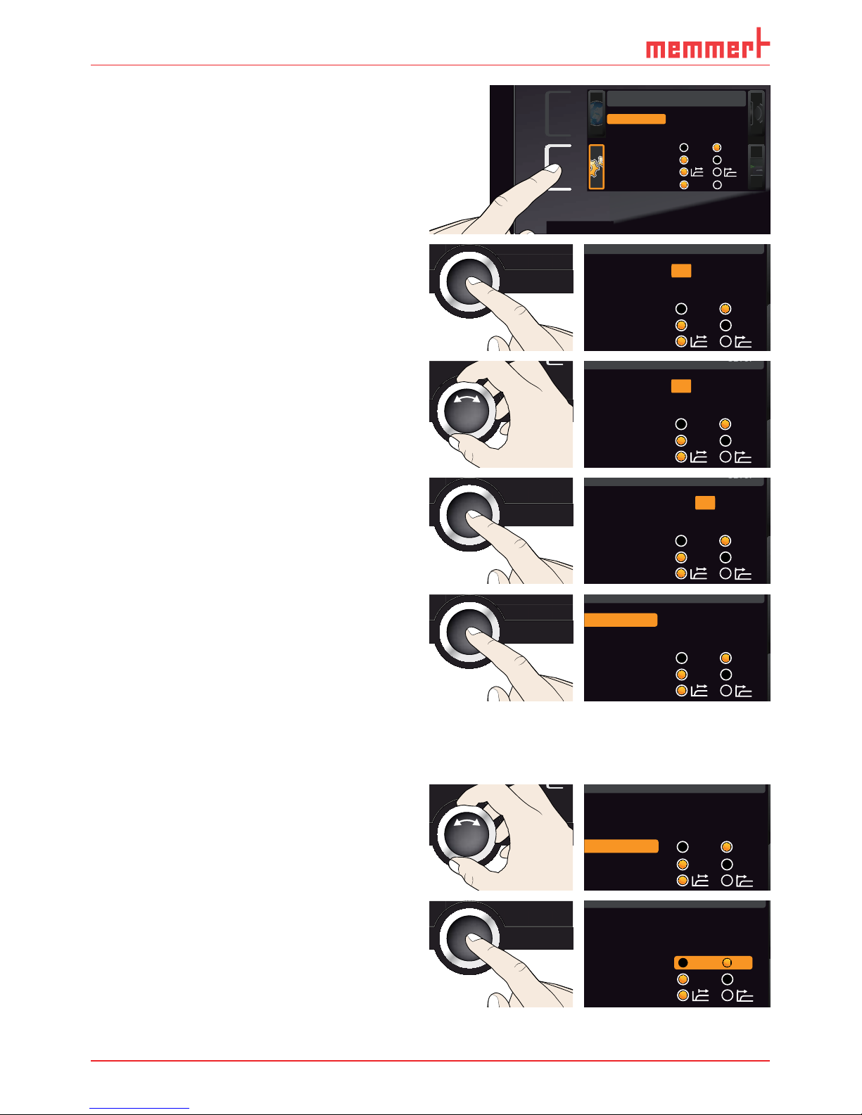
can make basic settings as well as adjust appliance parameters.
To
enter menu mode, press the MENU key.
To
SETUP
SIGNALTÖNE
CALIB
LANGUAGE
TIME
USER ID
344.4
444 4.
TEMP
Set
°C
°C
FLAP
40%
TIMER
hd
1002
End Sept.29 22 24
FAN
%0
1 2 3 4 5
6 7 8 9 10 11
Fig. 20
Language selection activation key
Language selection display
Language selection activation key
Language selection activation key
3
Date and time display
Language selection display
Language selection display
4
Date and time setting activation key
Date and time display
Date and time display
5
Return to manual mode
Date and time setting activation key
Date and time setting activation key
Setup activation key (basic appliance set-
tings)
Setup display (basic appliance settings)
8
Adjustment display
Setup display (basic appliance settings)
Setup display (basic appliance settings)
Adjustment activation key
Adjustment display
Adjustment display
with the turn control)
%
100
ALARM
max
444.4°C
auto
+
/
-
0.0K
min
444.4°C
Manu
44.Sept
Page 32

the change. A more detailed description is provided in the following, using the example of
Activate the desired parameter (in this
the corresponding activation key on the
LANGUAGE
ENGLISH
PROGRAM
PR
OG
TIME
D
O
OCO
DEUTSCH
ESPANOL
FRANCAIS
you have used to activate the display.
The appliance returns to the menu
SETUP
SIGNALTÖNE
PROG
ZEIT UND DATUM
CALIB
USER ID
PROTOCOL
LANGUAGE
PROGRAM
TIME
USER ID
PROTOCOL
SOUND
PLUS
ON
344.4
444 4.
TEMP
Set
°C
°C
FLAP
40%
TIMER
hd
1002
End Sept.29 2224
FAN
%0
%
100
ALARM
max
444.4°C
auto
+
/
-
0.0K
min
444.4°C
ONN
Manu
44.Sept
With the turn control, select the desired
%
100
ALARM
max
444.4°C
auto
+
/
-
0.0K
min
444.4°C
Manu
44.Sept
%
100
ALARM
max
444.4°C
auto
+
/
-
0.0K
min
444.4°C
Manu
44.Sept
SPRACHE
ENGLISH
DEUTSCH
ESPANOL
FRANCAIS
To return to the menu overview, press the
SETUP
SIGNALTÖNE
PROG
ZEIT UND DATUM
CALIB
USER ID
PROTOCOL
LANGUAGE
PROGRAM
TIME
USER ID
PROTOCOL
SOUND
PLUS
344.4
444 4.
TEMP
Set
°C
°C
FLAP
40%
TIMER
hd
1002
End Sept.29 2224
FAN
%0
%
100
ALARM
max
444.4°C
auto
+
/
-
0.0K
min
444.4°C
Manu
44.Sept
You can now
SETUP
Balance
PROGRAM
TIME
USER ID
PROTOCOL
PROGRAM
TIME
ER I
D
R
OTOCO
L
Einheit
IP Adresse
+30%
192.168.100.100
Alarm Temp
°C F
TWW TWB
Timer Mode
Setup
Unit
IP address
192.168.100.100
Subnet mask 255. 255.0.0
Alarm temp
°C F
TWW TWB
Timer mode
Slide-in unit
Grid Shelf
%
100
ALARM
max
444.4°C
auto
+
/
-
0.0K
min
444.4°C
Manu
44.Sept
SPRACHE
ENGLISH
DEUTSCH
ESPANOL
FRANCAIS
Page 33

All other settings can be made accordingly. The settings possible are described in the follow-
display, you can set the following parameters:
the
and
of the appliance's Ethernet interface (for connection to
the
of the temperature display (°C or °F, see page 34)
the type of temperature monitoring (TWW or TWB,
Alarm Temp
) and the trigger tem-
the
(see page 36)
the type of the slide-in unit (Grid or Shelf, see page 37)
To display the hidden entries, use the turn control
to scroll beyond the lowest entry. The page display
LAN 1: 192.168.1.233
192.168.1.216
LAN 2: 192.168.1.215
LAN 3: 192.168.1.241
Editor
Programmname
Simulation Protokoll
-
+-+
INP 250 Test 01
180
.0°C
i
HPP 250 Labor
i
37
.0°C
44
.4%rh
151
STAND BY
Programm negnulletsniEllokotorPtäreG efliHnekcurD
AtmoCONTROL
Fig. 21
network (schematic example)
Setup
Unit
IP adress 255.145.136. 225
Subnet mask 255.255. 0.0
°C F
1/2
Page 34
Activate the
display. The entry
is automatically highlighted.
SETUP
Balance
PROGRAM
TIME
USER ID
PROTOCOL
PROGRAM
TIME
ER I
D
R
OTOCO
L
Einheit
IP Adresse
+30%
192.168.100.100
Alarm Temp
°C F
TWW TWB
Timer Mode
Setup
Unit
IP address 192.168.100.100
Subnet mask 255. 255.0.0
Alarm temp
°C F
TWW TWB
Timer mode
Slide-in unit
Grid Shelf
Accept the selection by pressing the
the IP address are automatically selected.
%
100
ALARM
max
444.4°C
auto
+
/
-
0.0K
min
444.4°C
Manu
44.Sept
SETUP
Unit
IP address 192. 168.100.100
Subnet mask 255.255.0.0
Alarm temp
°C F
TWW TWB
Timer mode
With the turn control, set the new
%
100
ALARM
max
444.4°C
auto
+
/
-
0.0K
min
444.4°C
Manu
44.Sept
SETUP
Unit
IP address 255. 168.100.100
Subnet mask 255.255.0.0
Alarm temp
°C F
TWW TWB
Timer mode
Accept the selection by pressing the
turn control according to the description
%
100
ALARM
max
444.4°C
auto
+
/
-
0.0K
min
444.4°C
Manu
44.Sept
SETUP
Unit
IP address 255. 168.100.100
Subnet mask 255.255.0.0
Alarm temp
°C F
TWW TWB
Timer mode
After setting the last three digits, accept
the new IP address by pressing the
the overview.
The subnet mask is set accordingly.
%
100
ALARM
max
444.4°C
auto
+
/
-
0.0K
min
444.4°C
Manu
44.Sept
SETUP
Unit
IP address 255. 145.136.225
Subnet mask 255.255.0.0
Alarm temp
°C F
TWW TWB
Timer mode
Activate the
display and select
with the turn control.
%
100
ALARM
max
444.4°C
auto
+
/
-
0.0K
min
444.4°C
Manu
44.Sept
SETUP
Unit
IP address 255. 145.136.225
Subnet mask 255.255.0.0
Alarm temp
°C °F
TWW TWB
Timer mode
Accept the selection by pressing the
%
100
ALARM
max
444.4°C
auto
+
/
-
0.0K
min
444.4°C
Manu
44.Sept
SETUP
Unit
IP address 255. 145.136.225
Subnet mask 255.255.0.0
Alarm temp
Timer mode
TWW TWB
°C °F
Page 35

With the turn control, select the desired
%
100
ALARM
max
444.4°C
auto
+
/
-
0.0K
min
444.4°C
Manu
44.Sept
SETUP
Unit
IP address 255. 145.136.225
Subnet mask 255.255.0.0
Alarm temp
Timer mode
TWW TWB
°C °F
%
100
ALARM
max
444.4°C
auto
+
/
-
0.0K
min
444.4°C
Manu
44.Sept
SETUP
Unit
IP address 255. 145.136.225
Subnet mask 255.255.0.0
Alarm temp
°C °F
Timer mode
TWW TWB
Temperature monitoring (
Alarm Temp and Max Alarm)
from page 26) can be set (
Alarm Temp
), as well as the temperature at which the auto-
).
The monitoring temperature must be set sufficiently high above the maximum set tem-
Activate the
display and select
Alarm temp
with the turn control.
%
100
ALARM
max
444.4°C
auto
+
/
-
0.0K
min
444.4°C
Manu
44.Sept
SETUP
Unit
IP address 255.145.136.225
Subnet mask 255.255. 0.0
Alarm temp
°C F
TWW TWB
Timer mode
Accept the selection by pressing the
%
100
ALARM
max
444.4°C
auto
+
/
-
0.0K
min
444.4°C
Manu
44.Sept
SETUP
Unit
IP address 255.145.136.225
Subnet mask 255.255. 0.0
Alarm temp
°C F
TWW TWB
Timer mode
With the turn control, select the desired
%
100
ALARM
max
444.4°C
auto
+
/
-
0.0K
min
444.4°C
Manu
44.Sept
SETUP
Unit
IP address 255.145.136.225
Subnet mask 255.255. 0.0
Alarm temp
°C F
TWW TWB
Timer mode
%
100
ALARM
max
444.4°C
auto
+
/
-
0.0K
min
444.4°C
Manu
44.Sept
SETUP
Unit
IP address 255.145.136.225
Subnet mask 255.255. 0.0
Alarm temp
°C F
TWW TWB
Timer mode
S
with the turn control.
%
100
ALARM
max
444.4°C
auto
+
/
-
0.0K
min
444.4°C
Manu
44.Sept
SETUP
Max Alarm
190 °C
2/2
Page 36

Accept the selection by pressing the
%
100
ALARM
max
444.4°C
auto
+
/
-
0.0K
min
444.4°C
Manu
44.Sept
SETUP
Max Alarm
190 °C
2/2
With the turn control, select the desired
%
100
ALARM
max
444.4°C
auto
+
/
-
0.0K
min
444.4°C
Manu
44.Sept
SETUP
Max Alarm
160 °C
2/2
temperature monitoring system will
temperature reaches 160 °C.
%
100
ALARM
max
444.4°C
auto
+
/
-
0.0K
min
444.4°C
Manu
44.Sept
SETUP
Max Alarm
160 °C
2/2
Timer Mode
tolerance band of ±3 K around the set temperature is reached ( Fig. 22, B) or if it should start
t
Timer
t
Timer
A
B
°C/°F
t
6 K
Fig. 22
Timer Mode
A Timer independent of setpoint: Timer starts right after activation
Fig. 22
Fig. 22
B Timer setpoint-dependent: Timer does not start until tolerance band is reached
A Timer independent of setpoint: Timer starts right after activation
A Timer independent of setpoint: Timer starts right after activation
temperature is maintained for a sufficient period of time, this setting cannot be changed.
versal ovens UN/UF and incubators IN/IF, the timer is in this case interrupted and resumed
Page 37

Setting
Setting
Activate the
display and select
with the turn control.
%
100
ALARM
max
444.4°C
auto
+
/
-
0.0K
min
444.4°C
Manu
44.Sept
SETUP
Unit
IP address 255. 145.136.225
Subnet mask 255.255.0.0
Alarm temp
°C F
TWW TWB
Timer mode
Accept the selection by pressing the
%
100
ALARM
max
444.4°C
auto
+
/
-
0.0K
min
444.4°C
Manu
44.Sept
SETUP
Unit
IP address 255. 145.136.225
Subnet mask 255.255.0.0
Alarm temp
°C F
TWW TWB
Timer mode
With the turn control, select the
).
%
100
ALARM
max
444.4°C
auto
+
/
-
0.0K
min
444.4°C
Manu
44.Sept
SETUP
Unit
IP address 255. 145.136.225
Subnet mask 255.255.0.0
Alarm temp
°C F
TWW TWB
Timer mode
%
100
ALARM
max
444.4°C
auto
+
/
-
0.0K
min
444.4°C
Manu
44.Sept
SETUP
Unit
IP address 255. 145.136.225
Subnet mask 255.255.0.0
Alarm temp
°C F
TWW TWB
Timer mode
Type of the
when using optional sliding shelves instead of the grids that are part of the standard delivery.
Activate the
display and select
with the turn control.
%
100
ALARM
max
444.4°C
auto
+
/
-
0.0K
min
444.4°C
Manu
44.Sept
SETUP
Unit
IP adress 255.145.136. 225
Subnet mask 255.255.0.0
°C °F
Timer mode
Alarm temp
TWW TWB
Slide-in unit
Grid Shelf
Accept the selection by pressing the con-
firmation key. The adjustment options are
%
100
ALARM
max
444.4°C
auto
+
/
-
0.0K
min
444.4°C
Manu
44.Sept
SETUP
Unit
IP adress 255.145.136. 225
Subnet mask 255.255.0.0
°C °F
Timer mode
Alarm temp
TWW TWB
Slide-in unit
Grid Shelf
With the turn control, select the desired
%
100
ALARM
max
444.4°C
auto
+
/
-
0.0K
min
444.4°C
Manu
44.Sept
SETUP
Unit
IP adress 255.145.136. 225
Subnet mask 255.255.0.0
°C °F
Timer mode
Alarm temp
TWW TWB
Slide-in unit
Grid Shelf
Page 38

%
100
ALARM
max
444.4°C
auto
+
/
-
0.0K
min
444.4°C
Manu
44.Sept
SETUP
Unit
IP adress 255.145.136. 225
Subnet mask 255.255.0.0
°C °F
Timer mode
Alarm temp
TWW TWB
Slide-in unit
Grid Shelf
time
display, you can set the date and time, time zone and daylight savings.
Activate the time setting To do so, press
the activation key on the right side of
the
display. The display is enlarged
)
the current settings are shown.
Date and time
Time
Time zone
Daylight savings
12.05 . 2012
12:00
GMT +1
Date
– e.g. the time zone: Turn the turn
%
100
ALARM
max
444.4°C
auto
+
/
-
0.0K
min
444.4°C
Manu
44.Sept
TIME
Time
Daylight savings
12.05 .2012
12:00
GMT +1
Date
Time zone
Accept the selection by pressing the
this case the day – is automatically
%
100
ALARM
max
444.4°C
auto
+
/
-
0.0K
min
444.4°C
Manu
44.Sept
TIME
Time
Time zone
Daylight savings
.05. 2012
12:00
GMT +1
Date 12
With the turn control, set the current day,
%
100
ALARM
max
444.4°C
auto
+
/
-
0.0K
min
444.4°C
Manu
44.Sept
TIME
Time
Time zone
Daylight savings
.05. 2012
12:00
GMT +1
Date 27
%
100
ALARM
max
444.4°C
auto
+
/
-
0.0K
min
444.4°C
Manu
44.Sept
TIME
Time
Time zone
Daylight savings
. .2012
12:00
GMT +1
Date 27 05
Page 39

Accordingly, you can also set:
Year
Time zone
-11 -10 -9 -8 -7 -6 -5 -4 -3 -2 -1 0 +1 +2 +3 +4 +5 +6 +7 +8 +9 +10 +11
+12 -12-11
-11 -10 -9 -8 -7 -6 -5 -4 -3 -2 -1 0 +1 +2 +3 +4 +5 +6 +7 +8 +9 +10 +11
+12 -12-11
Fig. 23
Time zones
The appliances are temperature calibrated and adjusted at the factory. In case readjustment
Temperature calibration at low temperature
Page 40

CAL 1
+0,5 K
CAL 3
-0,8 K
CAL 2
+2,6 K
180°C
40°C
120°C
0°C
factory calibration
Fig. 24
Schematic example of temperature adjustment
Temperature deviation at 120 °C should be corrected.
Activate the adjustment setting. To do
display. The display
temperature – in this case 40 °C –
Cal1
°C -0,2
K
Cal2 100.0 °C +0,1K
Cal3 180.0 °C -0,2K
JUSTIEREN
Temperatur
PROGRAM
TIME
USER ID
PROTOCOL
PROGRAM
TIME
ER I
D
R
O
T
OCO
L
letzte Justierung 12.10.2012 12:00
40.0
C K0,2-
C K0,1+
C K0,2-
Calibration
Temperature
Last updated 12.10.2012 12:00:00
Cal1
Cal2
Cal3
100.0
180.0
40.0
%
100
ALARM
max
444.4°C
auto
+
/
-
0.0K
min
444.4°C
Manu
44.Sept
C K0,2-
C K0,1+
C K0,2-
JUSTIEREN
Temperature
Cal1
Cal2
Cal3
180.0
40.0
100.0
With the turn control, set the calibration
temperature Cal2 to 120 °C.
%
100
ALARM
max
444.4°C
auto
+
/
-
0.0K
min
444.4°C
Manu
44.Sept
C K0,2-
C K0,1+
C K0,2-
JUSTIEREN
Temperature
Cal1
Cal2
Cal3
180.0
40.0
120.0
%
100
ALARM
max
444.4°C
auto
+
/
-
0.0K
min
444.4°C
Manu
44.Sept
C K0,2-
C K
C K
0,2-
JUSTIEREN
Temperature
Cal1
Cal2
Cal3
180.0
40.0
120.0 0,1+
Page 41

%
100
ALARM
max
444.4°C
auto
+
/
-
0.0K
min
444.4°C
Manu
44.Sept
C K0,2-
C K
C K
0,2-
Calibration
Temperature
Cal1
Cal2
Cal3
180.0
40.0
120.0 0,0
21.4°C
TEMP
120.0 °CSet
Wait until the appliance reaches the set
temperature and displays 120 °C. The
120.0°C
TEMP
Set 120
.0°C
122.6 °C
%
100
ALARM
max
444.4°C
auto
+
/
-
0.0K
min
444.4°C
Manu
44.Sept
C K0,2-
C K
C K
0,2-
JUSTIEREN
Temperature
Cal1
Cal2
Cal3
180.0
40.0
120.0 2,6+
After the calibration procedure, the
temperature measured by the reference
°C
120.0°C
TEMP
Set 120
.0°C
120.0 °C
With Cal1, a calibration temperature below Cal2 can be programmed accordingly, and with
factory calibration settings are restored.
Page 42

Sterilisers SF/SN
The SF/SN appliance serves for sterilising medical material through dry heated air at
The product lifetime as intended by the manufacturer is eight years.
time to choose, as well as on packaging the sterilisation load. The values to be chosen depend
following process parameters have been defined in recognised standards:
According to WHO: 180 °C with a minimum hold time of 30 min
According to the European Pharmacopoeia: 160 °C with a minimum hold time of 120 min
the depletion of pyrogenic substances, you have to keep a combination of temperature and
time going beyond the requirements of sterilisation.
The temperature and time requirements normal for hot air sterilisation do
destroy
them will not be sufficient. For safe sterilisation, validation of the individual sterilisation
Page 43

Maintenance and service
Maintenance and service
Warning!
Warning!
Working chamber and metal surfaces
that could impair the appearance and functionality of the stainless steel working chamber
The metal surfaces of the appliance can be cleaned with normal stainless steel cleaning
the stainless steel housing. Rust deposits can lead to an infection of the stainless steel. If rust
Warning!
After removing covers, live parts may be exposed. You may
the mains plug before removing any covers. Any work inside
the appliance may only be performed by qualifi ed
Page 44

Storage and disposal
Storage
The appliance may only be stored under the following conditions:
frost-free
This product is subject to the Directive 2002/96/EC on Waste
August 13
th
The appliance may not be left at public or communal recycling or
Page 45

Index
A
Accessories 15
Activation key 24
Adjustment 39
Air flap position 25
Air supply 11
Alarm 35
Alarm temperature 35
Ambient conditions 14
Ambient temperature 15
Appliance error 30
AtmoCONTROL 3
,
,
value 41
,
,
toring 26
factory calibration 41
,
,
,
,
,
,
,
, , ,
,
Page 46

T
TB 28
Technical data 13
Temperature 25
Temperature comparison 39
Temperature deviation 40
Temperature limiter 28
Temperature monitoring 26
,
Time 37
,
Timer mode 36
Timer operation 25
Time zone 39
Transport 16
Transport damage 16
Turn control 24
TWB 26
TWW 26
W
Warning messages 12
,
Weight 13
Page 47

Page 48

Memmert GmbH + Co. KG
Willi-Memmert-Straße 90-96 | D-91186 Büchenbach
Tel. +49 9122 925-0 | Fax +49 9122 14585
E-Mail: sales@memmert.com
facebook.com/memmert.family
Die Experten-Plattform: www.atmosafe.net
Universal ovens
Incubators
Sterilisers
24.05.2013
D24022 // englisch
 Loading...