

Page 1

SNxx
PLUS
SFxx
PLUS
OPERATING
INSTRUCTIONS
STERILISER S
Page 2

Manufacturer and customer service
Memmert GmbH + Co. KG
Willi Memmert Straße 90-96
D-91186 Büchenbach
Deutschland
Phone: +49 (0)9122 925-0
Fax: +49 (0)9122 14585
E-mail: sales@memmert.com
Internet: www.memmert.com
Customer service:
Service hotline: +49 (0)9171 9792 911
Service fax: +49 (0)9171 9792 979
E-mail: service@memmert.com
When contacting customer service, always quote the product serial number on the nameplate
(see page 13
).
Shipping address for repairs:
Memmert GmbH + Co. KG
Kundenservice
Willi-Memmert-Str. 90-96
DE-91186 Büchenbach
Germany
Please contact our customer service before sending appliances for repair or before returning
equipment, otherwise, we have to refuse acceptance of the shipment.
© 2017 MEMMERT GmbH + Co. KG
D33340 | Date 08/2017
We reserve the right to make changes
Page 3

D33340 | Date 08/2017 3
About this manual
About this manual
Purpose and target group
This manual describes the assembly, function, transport and operation of sterilisers SNxxplus
and SFxxplus. It is intended for use by trained personnel of the owner, who have the task of
operating and/or maintaining the respective appliance.
If you are asked to work on the appliance, read this manual carefully before starting. Familiarise yourself with the safety regulations. Only perform work that is described in this manual. If
there is something you do not understand, or certain information is missing, ask your superior
or contact the manufacturer. Do not do anything without authorisation.
Versions
The appliances are available in different configurations and sizes. If specific equipment features or functions are available only for certain configurations, this is indicated at the relevant
points in this manual.
The functions described in this manual refer to the latest firmware version.
Due to individual configurations and sizes, illustrations in this manual may be slightly different
from the actual appearance. Function and operation are identical.
Other documents that have to be observed:
► For operation of the appliance with MEMMERT AtmoCONTROL, observe the respective
software manual. To open the AtmoCONTROL software manual, click on “Help” in the
AtmoCONTROL menu bar.
► For service and repair (see page 55), please refer to the separate service manual
Storage and forwarding
This instruction manual belongs with the appliance and should always be stored where
persons working on the appliance have access to it. It is the responsibility of the owner to
ensure that persons who are working or will work on the appliance are informed as to the
whereabouts of this instruction manual. We recommend that it is always stored in a protected
location close to the appliance. Make sure that the instruction manual is not damaged by heat
or humidity. If the appliance is sold on or transported and then set up again at a different
location, the operating instructions must go with it.
You will find the current version of our operating manual as pdf file if you go to
www.memmert.com/de/service/downloads/bedienungsanleitung/.
Page 4

4 D33340 | Date 08/2017
Contents
1. For your Safety 6
1.1 Terms and signs used........................................................................................................... 6
1.2 Product safety and dangers ................................................................................................ 7
1.3 Requirements of the operating personnel .......................................................................... 7
1.4 Responsibility of the owner ................................................................................................. 8
1.5 Intended use ........................................................................................................................ 8
1.6 Changes and alterations ...................................................................................................... 8
1.7 Behaviour in case of malfunctions and irregularities .......................................................... 9
1.8 Switching off the appliance in an emergency ....................................................................9
2. Construction and description 10
2.1 Construction ...................................................................................................................... 10
2.2 Function ............................................................................................................................. 11
2.3 Material.............................................................................................................................. 11
2.4 Electrical equipment .......................................................................................................... 11
2.5 Connections and interfaces ............................................................................................... 12
2.6 Designation (nameplate) ................................................................................................... 13
2.7 Technical data .................................................................................................................... 14
2.8 Applied directive ................................................................................................................ 15
2.9 Declaration of conformity ................................................................................................. 15
2.10 Ambient conditions ........................................................................................................... 15
2.11 Scope of delivery ...............................................................................................................16
2.12 Optional accessories .......................................................................................................... 16
3. Delivery, transport and setting up 17
3.1 For your Safety ................................................................................................................... 17
3.2 Delivery .............................................................................................................................. 18
3.3 Transport ............................................................................................................................ 18
3.4 Unpacking ......................................................................................................................... 18
3.5 Storage after delivery ........................................................................................................18
3.6 Setting up .......................................................................................................................... 19
4. Putting into operation 23
4.1 Connecting the appliance .................................................................................................23
4.2 Switching on ......................................................................................................................23
5. Operation and control 24
5.1 Operating personnel.......................................................................................................... 24
5.2 Opening the door .............................................................................................................. 24
5.3 Loading the appliance ....................................................................................................... 25
5.4 Operating the appliance .................................................................................................... 25
5.5 Temperature monitoring .................................................................................................. 32
5.6 Graph ................................................................................................................................. 36
5.7 Ending operation ...............................................................................................................36
6. Malfunctions, warning and error messages 37
6.1 Warning messages of the monitoring function ................................................................ 37
6.2 Malfunctions, operating problems and appliance errors ................................................ 38
6.3 Power failure ...................................................................................................................... 39
Contents
Page 5

D33340 | Date 08/2017 5
Contents
7. Menu mode 40
7.1 Overview ............................................................................................................................ 40
7.2 Basic operation in menu mode using the example of language selection ....................... 41
7.3 Setup.................................................................................................................................. 42
7.4 Date and Time ................................................................................................................... 46
7.5 Calibration ......................................................................................................................... 47
7.6 Programme ........................................................................................................................ 50
7.7 Sound ................................................................................................................................51
7.8 Protocol ............................................................................................................................. 52
7.9 User ID ............................................................................................................................... 53
8. Notes on sterilisation 54
8.1 Contraindications / unwanted side effects........................................................................ 54
8.2 Note in accordance with Medical Devices Directive ........................................................ 54
8.3 Guidelines for sterilisation .................................................................................................54
9. Maintenance and service 55
9.1 Cleaning ............................................................................................................................. 55
9.2 Regular maintenance.........................................................................................................55
9.3 Repairs and service ............................................................................................................ 55
10. Storage and disposal 56
10.1 Storage .............................................................................................................................. 56
10.2 Disposal ............................................................................................................................. 56
Index 57
Appendix 59
Page 6

6 D33340 | Date 08/2017
Safety regulations
1. For your Safety
1.1 Terms and signs used
In this manual and on the appliance itself, certain common terms and signs are used to warn
you of possible dangers or to give you hints that are important in avoiding injury or damage.
Observe and follow these hints and regulations to avoid accidents and damage. These terms
and signs are explained below.
1.1.1 Terms used
"Warning"
is used whenever you or somebody else could be injured if you do not
observe the accompanying safety regulation.
"Caution"
is used for information that is important for avoiding damage.
1.1.2 Signs used
Warning signs (warning of a danger)
Danger of
electrocution
Danger of
explosion
Dangerous
gases / va-
pours
Danger of
burns
Danger of
toppling
over
Hazard area!
Observe the op-
erating instruc-
tions
Prohibition signs (forbidding an action)
Do not lift Do not tilt Do not enter
Regulation signs (stipulating an action)
Disconnect
the mains
plug
Wear
gloves
Wear safety
boots
Observe
information
in separate
manual
Other icons
Important or useful additional information
Page 7
D33340 | Date 08/2017 7
Safety regulations
1.2 Product safety and dangers
The appliances described in this manual are technically sophisticated, manufactured using
high-quality materials and subject to many hours of testing in the factory. They contain the
latest technology and comply with recognised technical safety regulations. However, there are
still risks involved, even when the appliances are used as intended. These are described below.
Warning!
After removing covers, live parts may be exposed. You may receive
an electric shock if you touch these parts. Disconnect the mains plug
before removing any covers. Only electrical technicians may work on
the electrical equipment of the appliances.
Warning!
When loading the appliance with an unsuitable load, poisonous or
explosive vapours or gases may be produced. This could cause the
appliance to explode, and people could be severely injured or poisoned. The appliance may only be loaded with materials/test objects
which do not form any toxic or explosive vapours when heated up
(see also chapter Intended use on page 8).
Warning!
If the door is open while the appliance is in operation, the appliance
may overheat and pose a fi re hazard. Do not leave the door open
during operation.
Warning!
Depending on operation, the surfaces in the working chamber
and the chamber load may still be very hot after the appliance is
switched off. Touching these surfaces can cause burns. Wear heatresistant protective gloves or wait until the appliance cools down.
Warning!
In case of appliances of a certain size, you can get accidentally
locked in, which is life-threatening. Do not climb into the appliance!
1.3 Requirements of the operating personnel
The appliance may only be operated and maintained by persons who are of legal age and
have been instructed accordingly. Personnel who are to be trained, instructed or who are undergoing general training may only work with the appliance under the continuous supervision
of an experienced person.
Repairs may only be performed by qualified electricians. The regulations in the separate service
manual must be observed.
Page 8

8 D33340 | Date 08/2017
Safety regulations
1.4 Responsibility of the owner
The owner of the appliance
► is responsible for the flawless condition of the appliance and for its proper operation in
accordance with its intended use (see page 8);
► is responsible for ensuring that persons who are to operate or service the appliance are
qualified to do this, have been instructed accordingly and are familiar with the operating
instructions at hand;
► must know about the applicable guidelines, requirements and operational safety regula-
tions, and train staff accordingly;
► is responsible for ensuring that unauthorised persons have no access to the appliance;
► is responsible for ensuring that the maintenance plan is adhered to and that maintenance
work is carried out properly (see page 55);
► has to ensure that the appliance and its surroundings are kept clean and tidy, for example
through corresponding instructions and inspections;
► is responsible for ensuring that personal protective clothing is worn by operating person-
nel, e.g. work clothes, safety shoes and protective gloves.
1.5 Intended use
This appliance is exclusively intended for heating up non-explosive substances and objects.
Any other use is improper, and may result in hazards and damage.
The appliance is not explosion-proof (does not comply with the German workplace health &
safety regulation VBG 24). The appliance may only be loaded with materials and substances
which cannot form any toxic or explosive vapours at the set temperature and which cannot
explode, burst or ignite.
The appliance may not be used for drying, vaporising and branding paints or similar materials the solvents of which could form an explosive mixture when combined with air. If there
is any doubt as to the composition of materials, they must not be loaded into the appliance.
Potentially explosive gas-air mixtures must not form, neither in the working chamber nor in
the direct vicinity of the appliance.
Intended use
According to directive 93/42/EEC (Directive of the Commission on the harmonisation of the
legal regulations of the member states on medical devices) the intended use is defined as follows: The appliance serves for sterilising medical material through dry heated air at atmospheric pressure.
1.6 Changes and alterations
No unauthorised changes or alterations may be made to the appliance. No parts may be
added or inserted which have not been approved by the manufacturer.
Unauthorised modifications or changes result in the CE declaration of conformity losing its
validity and the appliance must no longer be operated.
The manufacturer is not liable for any damage, danger or injuries that result from unauthorised changes or alterations, or from non-observance of the regulations in this manual.
Page 9

D33340 | Date 08/2017 9
Safety regulations
1.7 Behaviour in case of malfunctions and irregularities
The appliance may only be used in a flawless condition. If you as the operator notice irregularities, malfunctions or damage, immediately take the appliance out of service and inform
your superior.
You can find information on correcting malfunctions from page 37.
1.8 Switching off the appliance in an emergency
Push the On/Off switch on the control panel
( Fig. 1 ) and disconnect power plug. This
disconnects the appliance from the power
supply at all poles.
Warning!
Depending on operation,
the surfaces in the working
chamber and the chamber
load may still be very hot after the appliance is switched
off. Touching these surfaces
can cause burns. Wear heatresistant protective gloves
or wait until the appliance
cools down.
ON
ONN
Fig. 1
Switch off the appliance by pressing the On/
Off switch
Page 10
10 D33340 | Date 08/2017
Construction and description
2. Construction and description
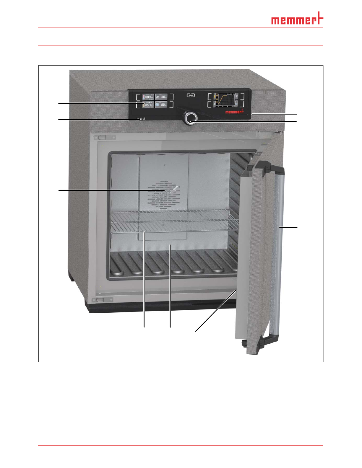
2.1 Construction
1
2
3
4 5 6
1
7
8
9
Fig. 2 Construction
1 ControlCOCKPIT with capacitive function
keys (see page 26)
2 On/Off switch (see page 23)
3 Working chamber fan (for
SFxxplus appliances only)
4 Steel grid
5 Working chamber
6 Nameplate (covered, see page 13)
7 Door handle (see page 24)
8 Turn control with confirmation key
9 USB interface (see page 12)
Page 11
D33340 | Date 08/2017 11
Construction and description
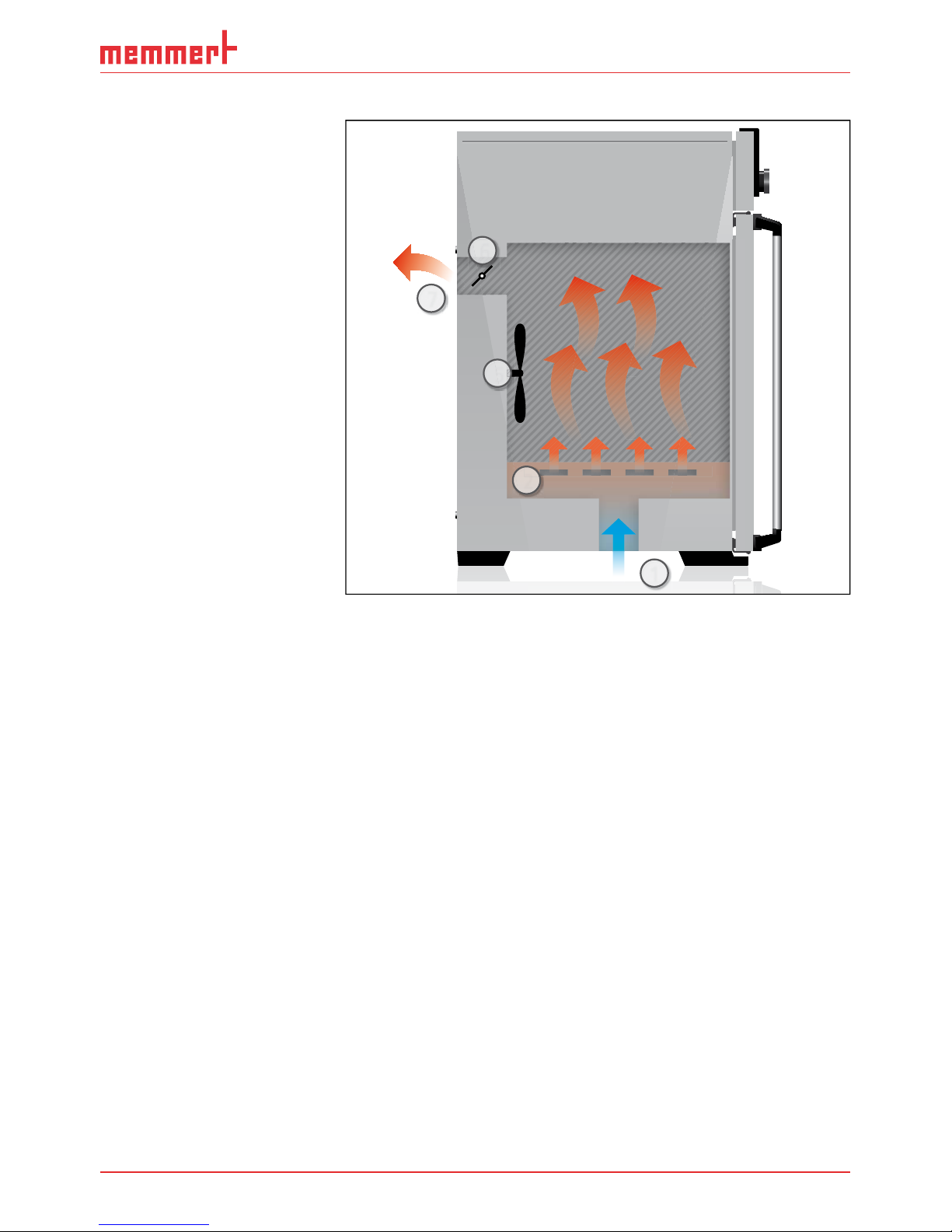
2.2 Function
Appliances of the SNxxplus
type series feature natural
circulation (convection).
For the SFxxplus type series,
air is circulated by a fan on
the rear panel of the interior
chamber (Fig. 3 , No. 1). It
increases the air flow and
provides stronger horizontal
forced air circulation than
natural convection.
In both the convection and
fan ventilated appliances,
supply air (2) is preheated
in a pre-heating chamber
(3). Through the ventilation
slits in the side panel of the
working chamber, the preheated air is introduced into
the interior of the chamber.
The supply and exhaust air
(5) volume (air change) is
controlled by the air flap
(4) on the rear panel of the
appliance.
2.3 Material
For the outer housing,
MEMMERT deploys stainless steel (Mat.No. 1.4016 – ASTM 430) and for the interior, stainless steel (Mat.No. 1.4301
– ASTM 304) is used, which stands out through its high stability, optimal hygienic properties
and corrosion-resistance towards many (but not all!) chemical compounds (caution for example with chlorine compounds).
The chamber load for the appliance must be carefully checked for chemical compatibility with
the materials mentioned. A material resistance table can be requested from the manufacturer.
2.4 Electrical equipment
► Operating voltage and current consumption: See nameplate
► Protection class I, i.e. operating insulation with PE conductor in accordance with EN 61010
► Protection type IP 20 acc. to EN 60 529
► Appliance fuse: Fusible link 250 V/15 A quick-blow
► The temperature controller is protected with a miniature fuse 100 mA (160 mA at 115 V)
4
1
2
5
3
Fig. 3 Function
1 Fan
2 Fresh air
3 Pre-heating chamber
4 Air flap
5 Exhaust air
Page 12
12 D33340 | Date 08/2017
Construction and description
2.5 Connections and interfaces
2.5.1 Electrical connection
This appliance is intended for operation on an electrical power system with a system impedance Z
max
of a maximum of 0.292 ohm at the point of transfer (service line). The operator
must ensure that the appliance is operated only on an electrical power system that meets
these requirements. If necessary, you can ask your local energy supply company what the
system impedance is.
Observe the country-specific regulations when connecting (e.g. in Germany
DIN VDE 0100 with residual current circuit breaker).
2.5.2 Communication interfaces
The interfaces are intended for appliances which meet the requirements of IEC 60950-1.
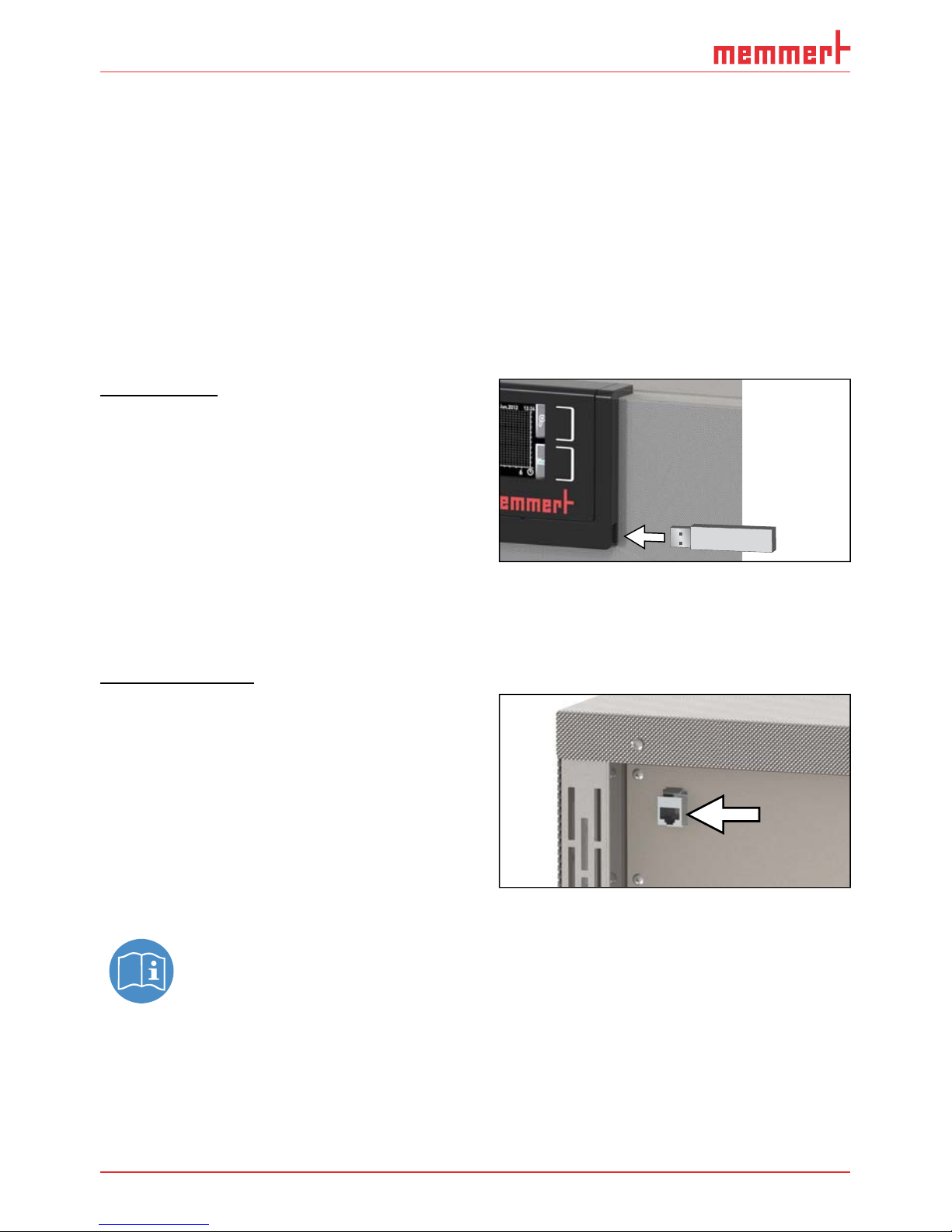
USB interface
The appliance is fitted by default with a USB
interface in accordance with the USB specification. This way, you can
► transfer software stored on a USB stor-
age medium to the appliance (see page
50).
► export protocol logs from the appliance
to a USB storage medium (see page
52).
► transfer user ID data stored on a USB storage medium to the appliance (see page 53).
The USB interface is located on the lower right of the ControlCOCKPIT (Fig. 4 ).
Ethernet interface
Via Ethernet interface, the appliance can be
connected to a network, so that you can
transfer programmes created with
AtmoCONTROL software to the appliance
and read out protocol logs. The Ethernet
interface is located on the rear of the
appliance (Fig. 5 ).
For identification purposes, each appliance
connected must have its own unique IP address. Setting the IP address is described on
page 42.
You will find a description of how to transfer programmes via Ethernet in the enclosed AtmoCONTROL manual.
With an optional USB to Ethernet converter, the appliance can be directly connected to a computer / laptop (see Scope of delivery on page 16).
Fig. 4 USB interface
Fig. 5 Ethernet interface
Page 13
D33340 | Date 08/2017 13
Construction and description
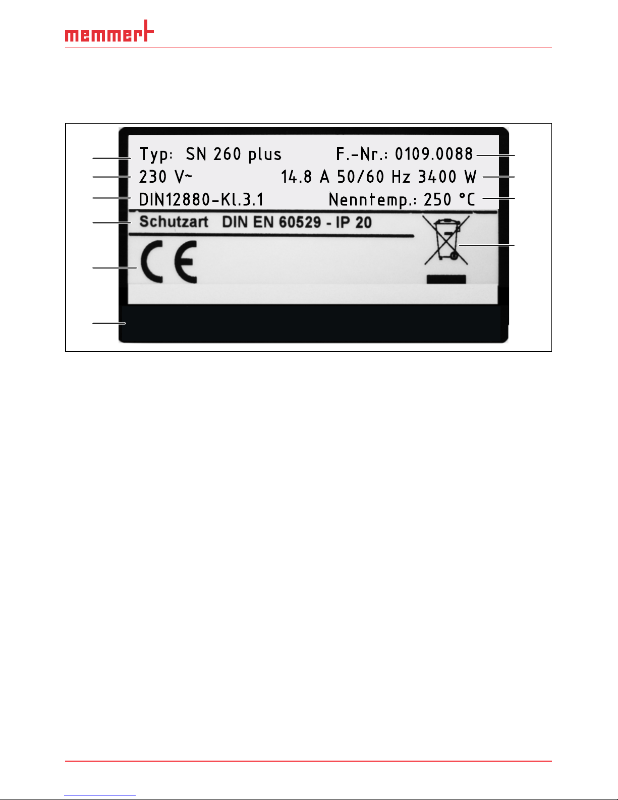
2.6 Designation ( nameplate)
The nameplate (Fig. 6) provides information about the appliance model, manufacturer and
technical data. It is attached to the front of the appliance, on the right side behind the door
(see page 10).
0197
memmert GmbH+Co.KG D-91126 Schwabach FRG
Äußere Rittersbacher Str. 38 Made in Germany
Typ: SN 260 plus F.-Nr.: 0109.0088
230 V
~
14.8 A 50/60 Hz 3400 W
DIN12880-Kl.3.1 Nenntemp.: 250 °C
1
2
3
4
5
6
10
8
9
7
Fig. 6 Nameplate (example)
1 Type designation
2 Operating voltage
3 Applied standard
4 Protection type
5 CE conformity with the number of the
notified body
6
7 Address of manufacturer
8 Disposal note
9 Temperature range
10 Connection / power ratings
11 Appliance number
Page 14

14 D33340 | Date 08/2017
Construction and description
2.7 Technical data
Appliance size 30 55 75 110 160 260 450 750 1060
Appliance width D
1
[mm] 585 585 585 745 745 824 1224 1224 1224
Appliance height E
1
[mm] 707 787 947 867 1107 1186 1247 1726 1726
Appliance depth G
1
(footprint) [mm] 434 514 514 584 584 684 784 784 1035
Depth of door lock [mm] 56
Appliance depth F
1
(including door handle) [mm] 490 570 570 640 640 740 840 840 1091
Working chamber width A
1
[mm] 400 400 400 560 560 640 1040 1040 1040
Working chamber height B
1
[mm] 320 400 560 480 720 800 720 1200 1200
Working chamber depth C
1
[mm] 250 330 330 400 400 500 600 600 850
Chamber volume [litres] 32 53 74 108 161 256 449 749 1060
Weight [kg] 48 57 66 78 96 110 170 217 252
Power [W]
230 V, 50/60 Hz 1600 2000 2500 2800 3200 3400 - - –
115 V, 50/60 Hz 1600 1700 1800 1800 1800 1800
-
-–
400 V, 50/60 Hz – 5800
2
7000
2
7000
2
3 x 208 V, 50/60 Hz – 4800 5700 5700
Current consumption [A]
230 V, 50/60 Hz 7,0 8,7 10,9 12,2 13,9 14,8 - - –
115 V, 50/60 Hz 13,9 14,8 15,5 15,5 15,5 15,5 - - –
400 V, 50/60 Hz – 3 x 8,4
2
3 x 10,2
2
3 x 10,2
2
3 x 208 V, 50/60 Hz – 3 x 13,3 3 x 15,1 3 x 15,1
max. number of sliding shelves 3 4 6 5 8 9 8 14 14
max. load per sliding shelve [kg] 20
30
60
max. load per appliance [kg] 60 80 120 175 210 300
Setting temperature range +20 to +250 °C
3
–
Adjustment precision up to 99.9 °C: 0.1 K, above 100 °C: 0.5 K
1
See Fig. 7 on page 15
2
3 x 230 V without neutral wire
3
With the interior lighting on, the minimum temperature might not be reached.
Page 15

D33340 | Date 08/2017 15
Construction and description
D
A
G
F
C
56
E
B
Fig. 7 Dimensions (see table on page 14)
2.8 Applied directive
Directive 93/42/EEC (Directive of the Commission on the harmonisation of the legal regulations of the member states on medical devices)
2.9 Declaration of conformity
You will find the EC declaration of conformity for the appliance enclosed in this manual.
2.10 Ambient conditions
► The appliance may only be used in enclosed rooms and under the following ambient
conditions:
Ambient temperature
+5 ºC to +40 ºC
Humidity rh max. 80 %, non-condensing
Overvoltage category II
Pollution degree 2
Altitude of installation max. 2,000 m above sea level
► The appliance may not be used in areas where there is a risk of explosion. The ambient air
must not contain any explosive dusts, gases, vapours or gas-air mixtures. The appliance is
not explosion-proof.
► Heavy dust production or aggressive vapours in the vicinity of the appliance could lead to
sedimentation in the interior and, as a consequence, could result in short circuits or damage to electrical parts. For this reason, sufficient measures to prevent large clouds of dust
or aggressive vapours from developing should be taken.
Page 16

16 D33340 | Date 08/2017
Construction and description
2.11 Scope of delivery
► Power cable
► Tilt protection
► One or two sliding steel grids (load capacity 30 kg each)
► USB storage medium with software and AtmoCONTROL manual
► The operating instructions at hand
► Calibration certificate
2.12 Optional accessories
► USB to Ethernet converter (Fig. 8). Makes it
possible to connect the appliance's
network interface (see page 12) to the
USB port of a computer / laptop.
► Reinforced, sliding steel grids with a load
capacity of 60 kg each (for appliance size
110 and larger)
Fig. 8 Converter USB to Ethernet
Page 17

D33340 | Date 08/2017 17
Delivery, transport and setting up
3. Delivery, transport and setting up
3.1 For your Safety
Warning!
Because of the heavy weight of the appliance, you could injure
yourself if you try to lift it. To carry appliances of the sizes 30 and
55, at least two persons, for appliances of the sizes 75, 110, 160 and
260, four people are needed. Appliances larger than that may not be
carried but must be transported with a manual pallet jack or forklift
truck.
30 55 75 110 160 260 450 750
Warning!
You may get your hands or feet squashed when transporting and installing the appliance. Wear protective gloves and
safety boots. When grasping the bottom of the appliance,
grasp it only on the sides:
9
Warning!
The appliance could fall over and seriously injure you. Never
tilt the appliance and transport it in upright position and
without load only (except for standard accessories such as
steel grids or shelves). Appliances with castors always have to
be moved by two people.
Page 18

18 D33340 | Date 08/2017
Delivery, transport and setting up
3.2 Delivery
The appliance is packed in cardboard and is delivered on a wooden palette.
3.3 Transport
The appliance can be transported in three ways:
► With a forklift truck; move the forks of the truck entirely under the pallet
► On a manual pallet jack
► On its own castors, in case of the corresponding configuration, for which the catch on the
(front) castors must be released
3.4 Unpacking
To avoid damage, do not unpack the appliance until you reach the installation site.
Remove the cardboard packaging by pulling it upwards or carefully cutting along an edge.
3.4.1 Checking for completeness and transport damage
► Check the delivery note to ensure that the delivery is complete.
► Check the appliance for damage.
If you notice deviations from the delivery note, damage or irregularities, do not put the appliance into operation but inform the haulage company and the manufacturer.
3.4.2 Removing the transport protection
Remove the transport protection. It is located between the door hinge, door and frame and
has to be removed after opening the door.
3.4.3 Disposing of packaging material
Dispose of the packaging material (cardboard, wood, foil) in accordance with the applicable
disposal regulations for the respective material in your country.
3.5 Storage after delivery
If the appliance is first to be stored after delivery: Read the storage conditions from page
56.
Page 19

D33340 | Date 08/2017 19
Delivery, transport and setting up
3.6 Setting up
Warning!
Due to its centre of gravity, the appliance can fall over to the front
and injure you or other people. Always attach the appliance to a wall
with the tilt protection (see page 21). If this cannot be done due
to space problems, do not operate the appliance and do not open
the door. Contact the Memmert service team (see page 2).
3.6.1 Prerequisites
The installation site must be flat and horizontal and must be able to reliably bear the weight
of the appliance (see "Technical data" on page 14). Do not place the appliance on a flammable surface.
Depending on the model (see nameplate), a 230 V, 115 V or 400 V power connection must be
available at the installation site.
The distance between the wall and the rear of the appliance must be at least 15 cm. The clearance from the ceiling must not be less than 20 cm and the side clearance from walls or nearby
appliances must not be less than 5 cm (Fig. 9). Sufficient air circulation in the vicinity of the
appliance must be guaranteed at all times.
For appliances with castors, these need to be positioned in forward direction at all times.
FP FP FP
FP
Fig. 9 Minimum clearance from walls and ceiling
Page 20

20 D33340 | Date 08/2017
Delivery, transport and setting up
3.6.2 Installation options
Setting up Comments Suitable for appliance size ...
30 55 75 110 160 260 450 750
Floor
Table
Check the load
capacity first
Stacked
two appliances
maximum; mounting material (feet)
provided
Wall
mounting
Separately packaged
fastening material is
included in the scope
of delivery. Observe
the assembly instructions provided.
Base
with/without castors
Castor
frame
Height ad-
justable feet
Page 21

D33340 | Date 08/2017 21
Delivery, transport and setting up
3.6.3 Tilt protection
Attach the appliance to a
wall with the tilt protection.
The tilt protection is included
in the delivery.
1. As illustrated, fasten the
tilt protection to the rear
side of the appliance.
2. Bend the tilt protec-
tion upwards by 90 ° in
the desired distance to
the wall (consider the
minimum distance to the
wall, see Fig. 9).
3. Drill a hole, insert a plug
and screw the tilt protection to a suitable wall.
Page 22

22 D33340 | Date 08/2017
Delivery, transport and setting up
3.6.4 Adjusting the doors (only for model sizes 450, 750 and 1060)
For model sizes 450, 750 and 1060, it is possible to adjust doors that warp due to the floor
conditions. In order to do so, every door has two adjuster screws at the top and at the bottom
(Fig. 10).
First, adjust the door at the top and then, if further adjustment is necessary, at the bottom
as well.
1. Open the door.
2. Undo the screws.
3. Adjust the door.
4. Tighten the screws again.
5. Check door alignment.
6. If necessary, readjust.
Fig. 10 Door adjustment screws
Page 23
D33340 | Date 08/2017 23
Putting into operation
4. Putting into operation
Caution:
The first time the appliance is operated, it must not be left unattended until it has reached
the steady state.
4.1 Connecting the appliance
Caution:
Observe the country-specific regulations when making connections (e.g. in Germany DIN
VDE 0100 with residual current circuit breaker). Observe the connection and power ratings (see nameplate and Technical data on page 14). Make sure to establish a safe PE
conductor connection.
Lay the power cable so that
► it is always accessible and within reach so it can be disconnected quickly in the event of
failure or emergencies;
► no one can trip over it;
► it does not come into contact with any hot parts.
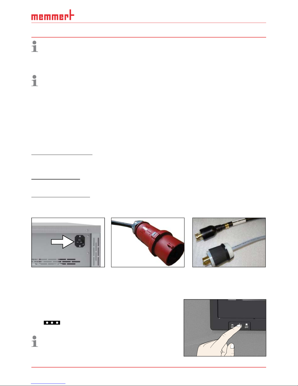
230/115-V appliances:
Plug the provided power cable into the rear of the appliance and connect it to a CEE 7/4
socket (Fig. 11).
400 V appliances:
The power cable is permanently installed. Connect the plug to a 400 V CEE coupling (Fig. 12).
3 x 208 V appliances:
The power cable is permanently installed. Connect the plug to a 3 x 208 V / 20 A coupling
(NEMA L15-20R) (Fig. 13).
Fig. 11 Power connection
230/115 V
Fig. 12
400 V CEE connection
Fig. 13 NEMA L15-20R
twist lock connection
4.2 Switching on
Switch on the appliance by pressing the On/Off switch
on the front of the appliance ( Fig. 14 ).
The starting process is shown by three animated white
dots
. If the dots have another colour, an error has
occurred (see page 39).
After the first start-up, the appliance display is set to
English by default. You can change the language as
described from page 41. However, to get a basic
overview of operating the appliance, you should read
the following chapter first.
ON
ONN
Fig. 14 Switch on appliance
Page 24

24 D33340 | Date 08/2017
Operation and control
5. Operation and control
Caution:
When loading and operating sterilisers of the SNxxplus/SFxxplus type, make sure to observe the special notes provided in chapter Notes on sterilisation from page 54.
5.1 Operating personnel
The appliance may only be operated by persons who are of legal age and have been instructed accordingly. Personnel who are to be trained, instructed or who are undergoing general
training may only work with the appliance under the continuous supervision of an experienced person.
5.2 Opening the door
► To open the door, pull the door handle to the side (to the left or to the right, depending
on the door variation, see Fig. 15, A) and open the door completely.
► To close the appliance, push the door closed and the door handle to the side (B).
A
B
Fig. 15 Opening and closing the door
Warning!
If the door is open while the appliance is in operation, the appliance
may overheat and pose a fi re hazard. Do not leave the door open
during operation.
Warning!
In case of appliances of a certain size, you can get accidentally
locked in, which is life-threatening. Do not climb into the appliance!
Page 25

D33340 | Date 08/2017 25
Operation and control
5.3 Loading the appliance
Warning!
When loading the appliance with an unsuitable load, poisonous
or explosive vapours or gases may be produced. This could cause
the appliance to explode, and persons could be severely injured or
poisoned. The appliance may only be loaded with materials which do
not form any toxic or explosive vapours when heated up and cannot
ignite (see also Intended use on page 8). If there is any doubt as
to the composition of materials, they must not be loaded into the
appliance.
Caution:
Check the chamber load for chemical compatibility with the materials of the appliance
(see page 11).
Insert the sliding steel grids or sliding shelves. The maximum number or grids / shelves and the
load capacity are specified in the technical data overview from page 14.
The chamber must not be
loaded too tightly, so that
proper air circulation in the
working chamber is guaranteed. Do not place any
chamber load on the floor,
touching the side walls or
right below the ceiling of the
working chamber (Fig. 16, see
also the "correct loading"
sticker on the appliance).
In case of improper loading
(chamber loaded too tightly),
the set temperature may
be exceeded or it may take
longer until it is reached.
To achieve the correct heating capacity, the type of slide-in unit used – Grid or Shelf –
must be set in the menu under
SETUP (see page 44).
5.4 Operating the appliance
5.4.1 ControlCOCKPIT
In manual operation, the desired parameters are entered at the ControlCOCKPIT on the front
of the appliance (Fig. 17 and Fig. 18). You can also make basic settings here (menu). Additionally, warning messages are displayed, e.g. if the temperature is exceeded. In programme
mode, the parameters defined, the programme description, the programme segment currently active and programme duration remaining are displayed (for a more detailed description, see page 30).
Fig. 16 Correct placement of the chamber load
Page 26

26 D33340 | Date 08/2017
Operation and control
ON
ONN
TIMER
End 14: 45
44h:44m
Holz trocknen
aufheizen
09:12h
Fr 20.10.2010 20:31
min
000°C
ALARM
of °C
max
000°C
auto off
99K
-
+
012
%rh°C
GRAPH
off
180.4°C
TEMP
Set 180
.4°C
ON
LIGHTONLIGHT
20%
FLAP
ON
ONN
FAN
%
0
FLAP
40%
LIGHT
%
100
ALARM
max
190.0°C
5.0K
min
160.0°C
auto
+
-
Manual Mode
12.Sept.2012
13:44
53 41314151612
19 2011 12 17 1867 8 910
TIMER
30m04h
Ende
13:30 23.11.
Fig. 17 ControlCOCKPIT for SFxxplus appliances in operating mode (width may differ depending on appliance size)
ON
ONN
180.0 °C
Set 180.9°C
TEMP
TIMER
End 14: 45
44h:44m
FLAP
Holz trocknen
aufheizen
09:12h
Fr 20.10.2010 20:31
min
000°C
ALARM
max
000°C
auto off
99K
-
+
012
%rh°C
GRAPH
off
ON
LIGHTONLIGHT
FLAP
40%
LIGHT
%
100
ALARM
max
190.0°C
5.0K
min
160.0°C
auto
+
-
Manual Mode
12.Sept.2012
13:44
12 513
10 11 12 19 2017 18
15 1614
TIMER
30m04h
Ende
13:30 23.11.
67 8 9
Fig. 18 ControlCOCKPIT for SNxxplus appliances in operating mode (width may differ depending on appliance size)
1 Activation key for temperature setpoint
adjustment
2 Setpoint and actual temperature display
3 Fan speed display
4 Activation key for fan speed setting
5 Switch to menu mode (see page 40)
6 Activation key digital backwards counter
with target time setting, adjustable from 1
minute to 99 days
7 On/Off switch
8 Display digital backwards counter with
target time setting, adjustable from 1 min-
ute to 99 days
9 Air flap position display
10 Activation key for air flap position adjust-
ment
11 Turn control for setpoint adjustment
12 Confirmation key (accepts setting made
with the turn control)
13 Activation key for interior lighting (ad-
ditional option)
14 Interior lighting display (additional option)
15 Appliance state and programme display
16 Activation key for the appliance state
17 Activation key for temperature monitoring
18 Temperature monitoring display
19 Graphic representation
20 Activation key for graphic representation
Page 27

D33340 | Date 08/2017 27
Operation and control
5.4.2 Basic operation
In general, all settings are made according to the following pattern:
1. Activate the desired parameter (e.g. temperature). To do so, press the corresponding activation key on the left or right or
the respective display. The activated display is lined in colour, the other displays
are dimmed. The set value is highlighted
in colour.
.5°C100
TEMP
TIMERmh
22.4°C
TEMP
37.0°CSet
2. By turning the turn control to the left
or right, adjust the set value (e.g. to
180.0 ºC).
22.4°C
TEMP
180.0°CSet
3. Save the set value by pressing the confirmation key.
The display returns to normal and the
appliance begins adjusting to the defined
set value.
23.2°C
TEMP
Set 180
.0°C
Additional parameters (air flap position etc.) can be set accordingly.
If no new values are entered or confirmed for approx. 30 seconds, the appliance automatically returns to the main menu and restores the former values.
If you want to cancel the setting procedure, press
the activation key on the left or right of the display that
you want to exit. The appliance restores the former
values. Only the settings that you have confirmed by
pressing the confirmation key before cancelling the
setting procedure are accepted.
5.4.3 Operating modes
The appliance can be operated in different modes:
► Manual mode: The appliance runs in permanent operation at the values set on the Con-
trolCOCKPIT. Operation in this mode is described in chapter 5.4.4.
► Operation with digital backwards counter with target time setting, adjustable from 1 min-
ute to 99 days (Timer): The appliance runs at the values set until the timer has elapsed.
Operation in this mode is described in chapter 5.4.5 .
► Programme mode: The appliance automatically runs programme sequences which have
been defined using AtmoCONTROL software at a computer / laptop and then transferred
to the appliance from a USB stick or via Ethernet. Operation in this mode is described in
chapter 5.4.6.
T
T
T
Page 28
28 D33340 | Date 08/2017
Operation and control
The status display shows you which operating mode or operating state the appliance is
currently in. The current operating state is highlighted in colour and indicated by the text
display:
Appliance is in programme mode
■ Programme is stopped
Appliance is in manual operating mode
The example on the right shows the appliance in manual mode, identified by the coloured hand symbol.
► When the appliance is in timer mode, Timer active is
displayed:
► When the appliance is in remote control mode, the
symbol appears in the temperature display:
5.4.4 Manual mode
In this operating mode, the appliance runs in permanent
operation at the values set on the ControlCOCKPIT.
Adjustment options
As described in chapter 5.4.2 , you can set the following
parameters after pressing the corresponding activation key (in any sequence):
Temperature
Adjustment range: model dependent (see nameplate and technical
date on page 14)
Heating operation is indicated by the
symbol.
You can select °C or °F as the temperature unit displayed (see
page 43).
24.4°C
TEMP
180.4 °CSet
Air flap position
Adjustment range: 0 % (closed, recirculating operation) to 100 %
(completely opened, fresh air operation) in steps of 10 %
FLAP
%40
Fan speed
(only for SFxxplus appliances)
Adjustment range: 0 to 100 % in steps of 10%
FAN
%
50
Interior lighting (additional option)
Adjustment range: 0 %, 100 %
LIGHT
%
100
Manual Mode
12.Sept.2012
13:44
Timer active
12.Sept.2012
13:44
23.2°C
TEMP
Set 38
.0°C
Page 29

D33340 | Date 08/2017 29
Operation and control
5.4.5 Operation with digital backwards counter with target time setting,
adjustable from 1 minute to 99 days ( Timer)
In timer operation, you can adjust the time the appliance runs at the set value. The appliance
has to be in manual operating mode for this.
1. Press the activation key to the left of
the timer display. The timer display is
activated.
TIMER
-
Ende
9:00 23.11.
--h- m
2. Turn the turn control until the desired
duration is displayed – in this example 4
hours 30 minutes. The approximate end
time is shown beneath, in a smaller font.
TIMER
End
0
13:30 23.11.
04 mh 3
Up to a duration of 23 hours 59 minutes, the time is displayed in hh:mm (hours:minutes)
format. For 24 hours and more, the format dd:hh (days:hours) is used. The maximum
duration adjustable is 99 days 00 hours.
3. Press the confirmation key to confirm.
The display now shows the remaining time
in a large font and the approximate end time
in a smaller font beneath. The status display
shows „Timer active“.
TIMER
30m04h
Ende
13:30 23.11.
Timer active
12.Sept.2012
13:44
4. Now, as described under 5.4.2 , set the individual values for temperature, air flap position
etc. which you want the appliance to operate at. It is not possible to change any parameters while the timer is counting down.
The timer only starts when the tolerance band of ±3 K around the set temperature has
been reached. If the temperature deviates from the tolerance band values, the timer starts
again (see page 44).
When the timer has elapsed, the display shows 00h:00m. All functions (heating etc.) are switched off. If a fan had been active, it will
keep on running for a short safety period. In addition, an acoustic
alarm sounds, which can be turned off by pressing the confirmation key.
To deactivate the timer, open the timer display by pressing the
activation key again and then turning the turn control to reduce
the timer setting until --:-- is displayed. Confirm with the confirmation key.
TIMER
00m00h
End
13:30 23.11.
TIMER
--m--h
End
9:00 23.11.
Page 30

30 D33340 | Date 08/2017
Operation and control
5.4.6 Programme mode
In this operating mode, programmes saved in the appliance can be started with different
combinations of individual parameters (temperature, air flap position, fan speed, working
chamber lighting) at staggered intervals, which the appliance then automatically processes in
sequence. These programmes are not created directly at the appliance but externally at a computer / laptop and using AtmoCONTROL software. Transfer to the appliance is possible using
the provided USB storage medium or via Ethernet.
A description of how to create and save programmes can be found in the separate
AtmoCONTROL software manual.
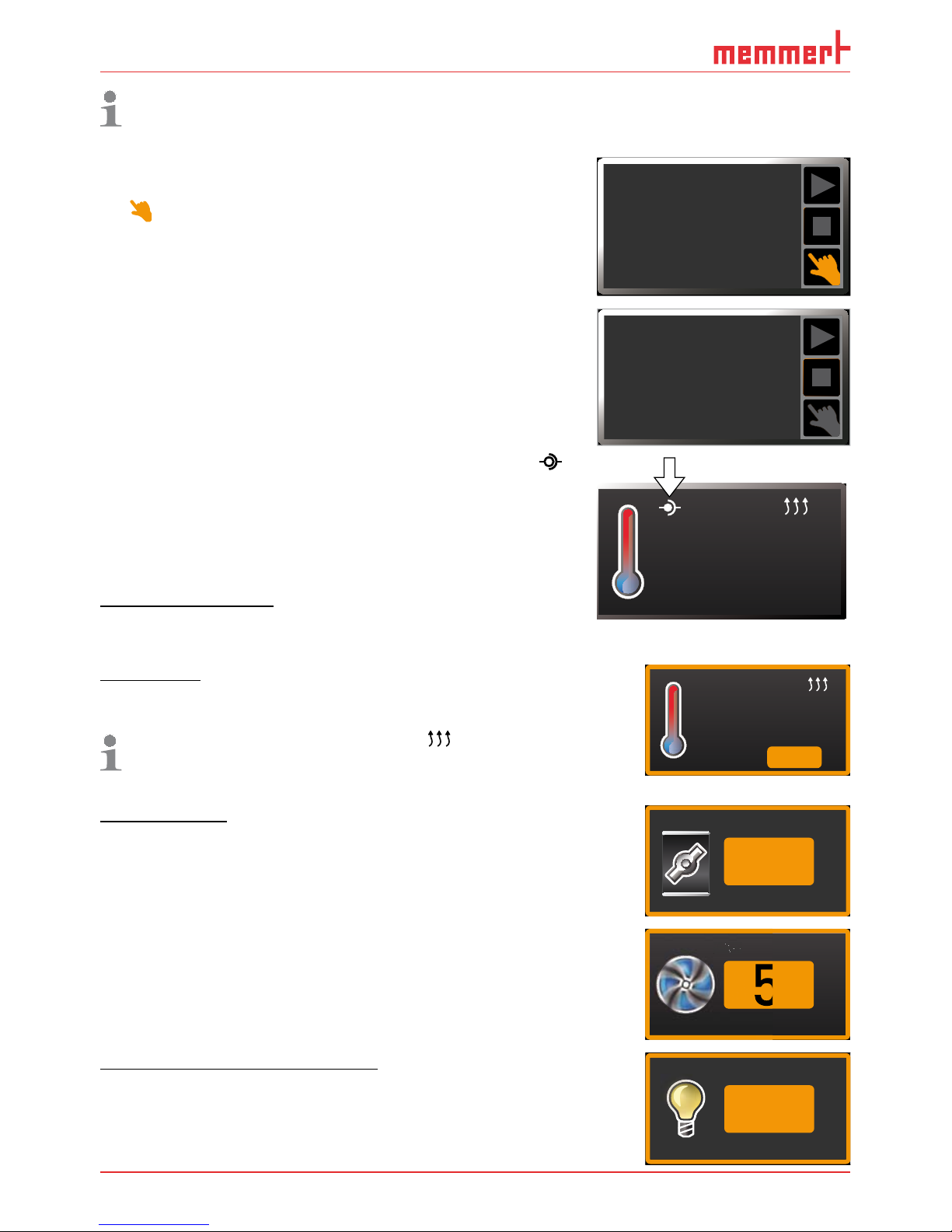
Starting a programme
1. Press the activation key to the right of
the status display. The current operating
mode is highlighted automatically, in this
example
Manual Mode ( ).
manueller Betrieb
Fr 20.10.2010 20:31
40
80
GRAPH
4
0
8
0
Manual mode
17:4413.Sept.2012
Activate
2. Turn the turn control until the start
symbol is highlighted. The current
programme is displayed, in this example
Test 012.
Test 012
ready
10:4412.Sept.2012
Only the programme currently selected in the menu and shown in the display can be
used. If you want to process another programme, you need to activate it in the menu
first (description from page 48 ).
3. To start the programme, press the confirmation key. The programme starts. The
display shows:
► the programme description (in this exam-
ple Test 012)
► the programme segment description, in
this example
Ramp 1
► the current run (in case of loops)
Test 012
Ramp 1
10:4412.Sept.2012
You cannot change any parameters (e.g. the temperature) at the appliance while a
programme is running. However, the displays
ALARM and GRAPH can still be used.
Page 31

D33340 | Date 08/2017 31
Operation and control
Cancelling a programme
You can cancel an active programme at any
time.
1. Press the activation key to the right of
the status display. The status display is
automatically highlighted.
%
manueller Betrieb
%
Fr 20.10.2010 20:31
°
80
GRAPH
8
0
Test 012
Ramp 3
10:4412.Sept.2012
2. Turn the turn control until the stop symbol
■
is highlighted.
Cancel program
Test 012
10:4812.Sept.2012
3. Press the confirmation key to confirm.
The programme is cancelled.
End
Test 012
10:4912.Sept.2012
A cancelled programme cannot be resumed at the point it was cancelled. It must be
restarted from the beginning.
End of programme
The display shows End when the programme
is finished.
End
Test 012
10:4912.Sept.2012
You can now
► restart the programme as described
► select another programme for processing in menu mode (see page 50) and run it as
described.
► return to manual mode. To do so,
reactivate it by pressing the activation key next to the status
display, then turn the turn control until the hand symbol
is highlighted in colour and press the confirmation key.
Manual Mode
12.Sept.2012
13:44
Page 32

32 D33340 | Date 08/2017
Operation and control
5.5 Temperature monitoring
The appliance is equipped with a multiple overtemperature protection (mechanical/electronic)
in accordance with DIN 12 880. This serves to avoid damage to the chamber load and/or appliance in case of a malfunction:
► electronic temperature monitoring (TWW)
► automatic temperature monitor ( ASF)
► mechanical temperature limiter (TB)
The monitoring temperature of the electronic temperature
monitoring is measured via a separate Pt100 temperature
sensor in the working chamber. Temperature monitoring
settings are made via the
ALARM display. The settings made
apply to all operating modes.
If temperature monitoring has been
triggered, this is indicated by the
temperature display: the actual temperature is highlighted in red and a warning
symbol
is shown ( Fig. 19). The type
of temperature monitoring triggered
(TWW in this example) is shown beneath
the temperature. If the acoustic alarm
has been activated in the menu mode
(
Sound, see page 51, indicated by the
speaker symbol in the alarm display), the
alarm is additionally signalled by an
intermittent acoustic signal, which can be turned off by pressing the confirmation key.
Information on what to do in this case are provided in the chapter Malfunctions, warning and
error messages from page 37.
Before reading how to adjust temperature monitoring (from page 34), please read the
description of the individual monitoring functions here.
ALARM
max
190.0°C
5.0K
min
160.0°C
auto
+
-
End 14: 45
44h:44m
°C
0°C
20%
FLAP
LÜFTER
%
0
LUFTKLAPPE
40%
TIMER
30m04h
Ende
23.11. 13:30
°C
0°C
TEMP
TWW Set 190.0
°C
195.4°C
180.4°C
TEMP
Set 185
.0°C
23.2°C
TEMP
Set 180
.0°C
TEMP
TWW Set 190.0 °C
195.4°C
Fig. 19
Temperature monitoring triggered
Page 33

D33340 | Date 08/2017 33
Operation and control
5.5.1 Electronic temperature monitoring ( TWW)
The manually set monitoring temperature min and max of the electronic overtemperature
control is monitored by an adjustable over/undertemperature controller (TWW) protection
class 3.1 acc. to DIN 12 880 (or over/undertemperature controller (TWW) protection class 3.1
for UIS appliances). If the manually set monitoring temperature
max is exceeded, the TWW
takes over temperature control and begins to regulate the monitoring temperature (Fig. 20).
t
°C
Setting MAX
Set temperature
Controller error
Emergency operation
Fig. 20 Schematic diagram of how the TWW temperature monitoring works
5.5.2 Electronic temperature limiter ( TWB) protection class 2 acc. to DIN 12 880
If the manually set monitoring temperature max is exceeded, the TWB switches off heating
permanently (Fig. 21 ) and can be reset by pressing the confirmation key.
In programme mode, the current programme is resumed for TWB alarms of up to 15
minutes. If the alarm is active for more than 15 minutes, the programme is cancelled.
t
°C
heating switched off by TWB
Setting Max
Set temperature
Controller error
Fig. 21 Schematic diagram of how the TWB temperature monitoring works
Page 34

34 D33340 | Date 08/2017
Operation and control
5.5.3 Automatic temperature monitor ( ASF)
ASF is a monitoring device that automatically follows the set temperature setpoint within an
adjustable tolerance band (Fig. 22).
The ASF – if switched on – is automatically activated as soon as the actual temperature value
reaches 50 % of the set tolerance band of the setpoint (in the example: 180 °C – 1.5 K) for the
first time (section A).
When the temperature violates the set tolerance band around the setpoint (in the example in
Fig. 22:
180 °C ± 3 K) – e.g. if the door is opened during operation (section B of illustration) – the
alarm is set off. The ASF alarm is automatically triggered as soon as 50 % of the set tolerance
band of the setpoint (in the example: 180 °C ± 1.5 K) are reached again (section C).
If the temperature setpoint is altered, the ASF is automatically disabled temporarily (in this
example: The setpoint is changed from 180 °C to 173 °C, section D) until the tolerance range
of the new temperature setpoint is reached again (section E).
183 °C
177 °C
ASF active
183 °C
177 °C
ASF alarm
ASF active ASF active
176 °C
170 °C
180 °C
t
ABCDE
AUTO AUTO AUTO
Fig. 22 Schematic diagram of how the ASF temperature monitoring works
5.5.4 Mechanical temperature monitoring: Temperature limiter ( TB)
The appliance is equipped with a mechanical temperature limiter (TB) of protection class 1 in
accordance with DIN 12 880.
If the electronic monitoring unit should fail during operation and the factory-set maximum
temperature is exceeded by approx. 20 °C, the temperature limiter, as the final protective
measure, switches off the heating permanently.
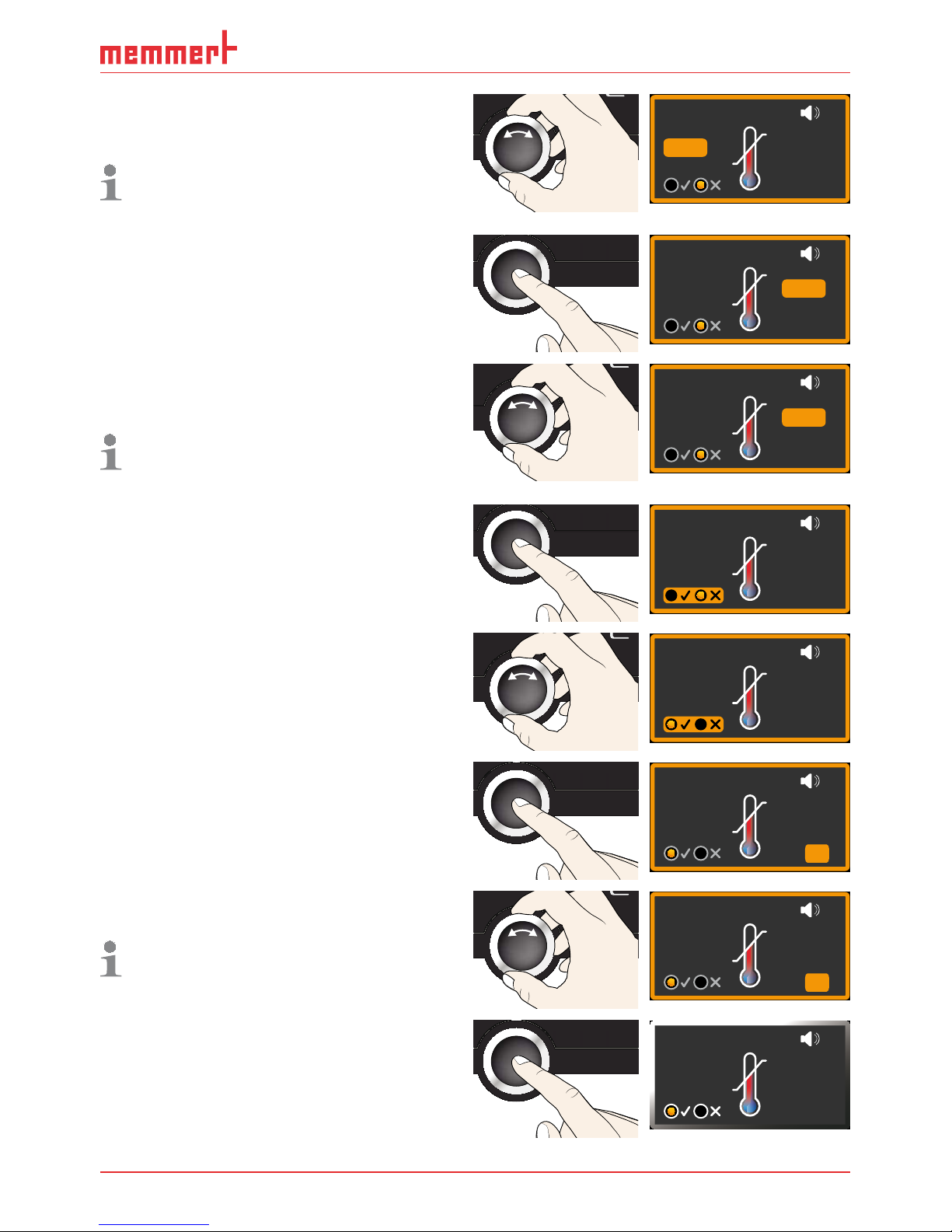
5.5.5 Adjusting temperature monitoring
1. Press the activation key to the left of the
ALARM display. The min setting (under-
temperature protection) is automatically
activated.
min
000°C
ALARM
max
000°C
auto off
99K
-
+
ALARM
+
-
0.0K
min
°C
auto
max
120.0°C600.
Page 35
D33340 | Date 08/2017 35
Operation and control
2. By turning the turn control, adjust the
desired lower alarm limit value, in the
example on the right 160 °C.
If no undertemperature protection limit is
required, set the lowest temperature.
ALARM
0.0K
min
°C
auto
max
120.0°C
1600.
+
-
3. Press the confirmation key to confirm.
The
max display (overtemperature pro-
tection) is activated.
ALARM
0.0K
min
°C
auto
max
°C1600. 120 0.
+
-
4. By turning the turn control, adjust the
desired upper alarm limit value, in the
example on the right 190 °C.
The monitoring temperature must be set
sufficiently high above the maximum set
temperature. We recommend 5 to 10 K.
ALARM
0.0K
min
°C
auto
max
°C1600. 190 0.
+
-
5. Accept the upper alarm limit value by
pressing the confirmation key. The setting
of the automatic temperature monitor
(ASF) is automatically activated (
auto).
ALARM
max
190.0°C
0.0K
min
160.0°C
auto
+
-
6. With the turn control, select ON () or
OFF ().
ALARM
max
190.0°C
0.0K
min
160.0°C
auto
+
-
7. Press the confirmation key to confirm.
The ASF tolerance band setting is activated.
ALARM
K
min
°C
auto
max
190.0°C160 0.
0.3
+
-
8. With the turn control, adjust the desired
tolerance band, e.g. 5.0 K.
We recommend a tolerance band of 5 to
10 K.
ALARM
K
min
°C
auto
max
190.0°C160 0.
5.0
+
-
9. Press the confirmation key to confirm.
Temperature monitoring is now active.
ALARM
max
190.0°C
5.0K
min
160.0°C
auto
+
-
Page 36

36 D33340 | Date 08/2017
Operation and control
In the menu, you can set:
► which type of protection (TWW or TWB) should be active (see page 43)
► if an acoustic signal should be triggered on alarm (see page 51)
5.6 Graph
The GRAPH display provides an overview of the chronological sequence of the set values and
the actual values as a curve.
1. Press the activation key to the
right of the
GRAPH display.
The display is enlarged and
the temperature profile
shown.
0 4 8 12162024
C
40
20
60
80
00
Fr 20.10.2010 20:34
12.09.2012
14.00 16.00 18.00
► To change the time frame to
be displayed: Press the activation key next to the arrow symbols. The time frame
to be displayed can now be
changed by turning the turn
control.
0 4 8 12162024
°C
40
20
60
80
100
Fr 20.10.2010 20
:
12.09.2012
14.00 16.00 18.00
► To zoom the graph in or out:
Press the activation key next
to the magnifying glass symbol. Select whether you want
to zoom in or out (+/–) with
the turn control and confirm
your selection by pressing the
confirmation key.
.2010 20:34
2
To close the graphical representation, again press the activation key which you have used to
activate it.
5.7 Ending operation
Warning!
Depending on the operation performed, the surfaces in the working
chamber and the chamber load may still be very hot after the appli-
ance is switched off. Touching these surfaces can cause burns. Wear
heat-resistant protective gloves or wait until the appliance cools
down.
1. Switch off active appliance functions
(turn back the set values).
2. Remove the chamber load.
3. Switch off the appliance (Fig. 23 ).
ON
ONN
Fig. 23 Switch off appliance
Page 37

D33340 | Date 08/2017 37
Malfunctions, warning and error messages
6. Malfunctions, warning and error messages
Warning!
After removing covers, live parts may be exposed. You may receive
an electric shock if you touch these parts. Malfunctions requiring
work inside the appliance may only be rectifi ed by electricians. Ob-
serve the separate service manual for this.
Do not try to rectify appliance errors yourself but contact the MEMMERT customer service
department (see page 2) or an authorised service point.
In case of enquiries, please always specify the model and appliance number from the nameplate (see page 13).
6.1 Warning messages of the monitoring function
If the acoustic alarm has been activated in the Signals menu (see
page 51), which is indicated by the speaker symbol
in the
alarm display, the alarm is additionally signalled by an intermittent acoustic signal. If the confirmation key is pressed, the
acoustic alarm can be temporarily switched off until the next
alarm event occurs.
6.1.1 Temperature monitoring
Description Cause Action See
Temperature alarm and
"ASF" are displayed
TEMP
ASF Set 190.0 °C
185.4°C
Automatic temperature monitor
(ASF) triggered
Check if the door is closed. Close
the door.
Extend the ASF tolerance band
If the alarm continues: Contact
customer service
page
35
page 2
Temperature alarm and
"TWW" are displayed
TEMP
TWW Set 190.0 °C
195.4°C
The adjustable
undertemperature
/ overtemperature
controller (TWW)
has assumed heating control.
Increase the difference between
the monitoring and setpoint
temperature – by either increasing the max value of the temperature monitoring or decreasing
the setpoint temperature.
If the alarm continues: Contact
customer service
page
34
page 2
Page 38

38 D33340 | Date 08/2017
Malfunctions, warning and error messages
Description Cause Action See
Temperature alarm and
"TWB" are displayed
TEMP
TWB Set 190.0 °C
195.4°C
The electronic
temperature
limiter (TWB) permanently switched
off heating.
Deactivate the alarm by pressing
the confirmation key.
Increase the difference between
the monitoring and setpoint
temperature – by either increasing the max value of the temperature monitoring or decreasing
the setpoint temperature.
If the alarm continues: Contact
customer service
page
34
page 2
Temperature alarm and
"TB" are displayed
TEMP
TB
230.4 °C
The mechanical
temperature limiter (TB) permanently switched
off heating.
Switch off the appliance and
leave to cool down. Contact
customer service and have the
error rectified (e.g. by replacing
the temperature sensor).
page 2
6.2 Malfunctions, operating problems and appliance errors
Error description Cause of error Rectifying errors See
Displays are dark External power supply
was interrupted
Check the
power supply
page
23
Miniature fuse, appliance
fuse or power module
faulty
Contact customer
service
page 2
Displays cannot be
activated
Appliance locked by user ID Unlock with user ID page
53
The appliance is in programme, timer or remote
control mode (mode "Write"
or "Write + Alarm")
Wait until the end of
the programme or
timer mode or switch
off the remote control
Displays suddenly look
different
Appliance is in "wrong"
mode
Change to operating or
menu mode by pressing
the MENU key
Page 39

D33340 | Date 08/2017 39
Malfunctions, warning and error messages
Error description Cause of error Rectifying errors See
Display T:E-3 in the
temperature display
TEMP
T:E-3 Set 37.0 °C
37.4°C
Temperature operating sensor defective. The monitoring sensor takes over the
measurement function.
► The appliance can
be temporarily operated
► Contact customer
service as soon as
possible
page 2
Error message AI E-3 in
the temperature display
TEMP
AI E-3 Set 37.0 °C
37.4°C
Temperature monitoring
sensor defective. The operating sensor takes over the
measurement function.
► The appliance can
temporarily be kept
in service
► Contact customer
service as soon as
possible page 2
Error message E-3 in
the temperature display
TEMP
Set 45.0 °C
E-3 °C
Operating and monitoring
sensor defective
► Switch off appli-
ance.
► Remove the cham-
ber load
► Contact customer
service
page 2
When switching on
the appliance, the start
animation is displayed
in another colour than
white
► Cyan :
Not enough storage
space on the SD card
► Red :
The system files could
not be loaded
► Orange : The
fonts and images could
not be loaded
Contact customer
service
Contact customer
service
Download the firmware
update at memmert.
com and install it
page 2
page 2
6.3 Power failure
In case of a power failure, the appliance operates as follows:
In manual mode
After power supply has been restored, operation is continued with the parameters set. The
time and duration of the power failure are documented in the log memory.
In timer or programme mode
After power supply has been restored, the timer or programme always starts again from the
beginning.
Page 40

40 D33340 | Date 08/2017
Menu functions
7. Menu mode
In menu mode, you can make basic settings, load programmes and export protocols, as well
as adjust appliance parameters.
Caution:
Before changing menu settings, read the description of the respective functions on the following pages to avoid possible damage to the appliance and/or chamber load.
To enter menu mode, press the MENU key.
To exit the menu mode at any time, press the MENU key
again. The appliance then returns to manual mode. Only
changes accepted by pressing the confirmation key are
saved.
7.1 Overview
Press the MENU key to change between the displays in menu mode:
SETUP
SIGNALTÖNE
PROG
ZEIT UND DATUM
CALIB
USER ID
PROTOCOL
LANGUAGE
TIME
SOUND
ON
ONN
12 34 512141513
67 18 1989 1011 16 17
Fig. 24 ControlCOCKPIT in menu mode
1 Language selection activation key
2 Language selection display
3 Date and time display
4 Date and time setting activation key
5 Exit menu mode and return to manual
mode
6 Setup activation key (basic appliance set-
tings)
7 Setup display (basic appliance settings)
8 Adjustment display
9 Adjustment activation key
10 Turn control for adjustment
11 Confirmation key (accepts setting made
with the turn control)
12 Programme setup activation key
13 Programme setup display
14 Protocol display
15 Protocol activation key
16 Acoustic signal adjustment activation key
17 Acoustic signal adjustment display
18 User ID display
19 User ID activation key
Page 41
D33340 | Date 08/2017 41
Menu functions
7.2 Basic operation in menu mode using the example of language
selection
In general, all settings in menu mode are done just like in manual mode: Activate the respective display, use the turn control for setting and press the confirmation key to accept
the change. A more detailed description is provided in the following, using the example of
language selection.
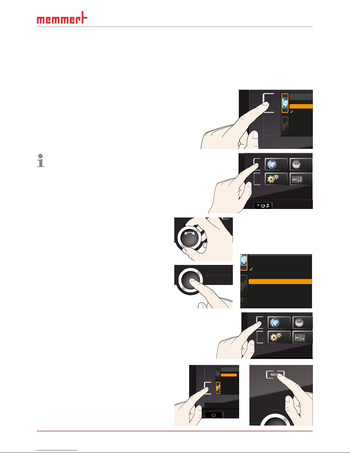
1. Activate the desired parameter (in this
example the language). To do so, press
the corresponding activation key on the
left or right of the respective display. The
activated display is enlarged.
ENGLISH
DEUTSCH
ESPANOL
FRANCAIS
If you want to exit or cancel your settings,
again press the activation key which you
have used to activate the display. The
appliance returns to the menu overview.
Only the settings that you have confirmed by pressing the confirmation key
before cancelling the setting procedure
are accepted.
SETUP
SIGNALTÖNE
CALIB
LANGUAGE
TIME
ON
ONN
2. With the turn control, select the desired
new setting, e.g. Español (Spanish).
3. Save the setting by pressing the confir-
mation key.
ENGLISH
DEUTSCH
ESPANOL
FRANCAIS
4. To return to the menu overview, press the
activation key again.
SETUP
SIGNALTÖ
N
CALI
B
LANGUAGE
TIM
You can now
► activate another menu function by press-
ing the corresponding activation key or
► return to manual mode by pressing the
MENU key.
Balance
Einheit
IP Adresse
Alarm Temp
Timer Mode
Unit
IP address
Subnet mask
Alarm temp
Timer mode
Slide-in unit
ENGLISH
DEUTSCH
ESPANOL
FRANCAIS
Page 42

42 D33340 | Date 08/2017
Menu functions
All other settings can be made accordingly. The settings possible are described in the following sections.
If no new values are entered or confirmed for approx. 30 seconds, the appliance automatically returns to the main menu and restores the former values.
7.3 Setup
7.3.1 Overview
In the SETUP display, you can set the following parameters:
► the IP address and Subnet mask of the appliance's Ethernet interface (for connection to
a network)
► the Unit of the temperature display (°C or °F, see page 43)
► Alarm temp: the temperature protection class according to DIN 12 880:2007-5 (TWW or
TWB, see pages 43 and 32)
► how the digital backwards counter with target time setting works (Timer mode, see page
44)
► the type of the slide-in unit (Grid or Shelf, see page 44)
► the heat output distribution (Balance, see page 44)
► Remote control (see page 45)
► Gateway (see page 46)
If the SETUP menu contains more entries than can be
displayed, this is indicated by the display “1/2”. This
means that there is a second „page“ of entries.
To display the hidden entries, use the turn control
to scroll beyond the lowest entry. The page display
changes to “2/2”.
7.3.2 IP address and subnet mask
If you want to operate one ore more appliances in a network, each appliance must have its
own unique IP address for identification. By default, each appliance is delivered with the IP
address 192.168.100.100.
LAN 1: 192.168.1.233
192.168.1.216
LAN 2: 192.168.1.215
LAN 3: 192.168.1.241
192.168.
1
Editor
Programmname
Simulation Protokoll
-
+-+
INP 250 Test 01
180
.0°C
i
HPP 250 Labor
i
37
.0°C
44
.4%rh
151
STAND BY
Programm negnulletsniEllokotorPtäreG efliHnekcurD
AtmoCONTROL
Fig. 25 Operation of several appliances in a network (schematic example)
Setu
p
Unit
IP adress 255.145.136.
2
Subnet mask 255. 255.0. 0
°C F
1/2
Page 43

D33340 | Date 08/2017 43
Menu functions
1. Activate the
SETUP display. The entry IP
address is automatically highlighted.
SETUP
Balance
Einheit
IP Adresse
+30%
192.168. 10 0. 100
Alarm Temp
°C F
TWW TWB
Timer Mode
Setup
Unit
IP address 192.168. 10 0. 100
Subnet mask 255.255.0. 0
Alarm temp
°C F
TWW TWB
Timer mode
Slide-in unit
Grid Shelf
2. Accept the selection by pressing the confirmation key. The first three digits of the
IP address are automatically selected.
Unit
IP address 192.168.100.100
Subnet mask 255.255.0.0
Alarm temp
°C F
TWW TWB
Timer mode
Slide-in unit
Grid Shelf
3. With the turn control, set the new number, e.g. 255.
Unit
IP address 255.168.100.100
Subnet mask 255.255.0.0
Alarm temp
°C F
TWW TWB
Timer mode
Slide-in unit
Grid Shelf
4. Accept the selection by pressing the
confirmation key. The next three digits of
the IP address are automatically selected.
Setting these is done according to the
description above.
Unit
IP address 255. 168.100.100
Subnet mask 255.255.0.0
Alarm temp
°C F
TWW TWB
Timer mode
Slide-in unit
Grid Shelf
5. After setting the last three digits, accept
the new IP address by pressing the confirmation key. The selection returns to the
overview.
The subnet mask is set accordingly.
Unit
IP address 255. 145.136.225
Subnet mask 255.255.0.0
Alarm temp
°C F
TWW TWB
Timer mode
Slide-in unit
Grid Shelf
7.3.3 Unit
Here, you can choose whether the temperature is displayed in °C
or °F.
7.3.4 Temperature monitoring (Alarm Temp)
Here, you can choose which temperature protection class in
accordance with DIN 12 880:2007-5 should be used (TWW or
TWB, description from page 32).
Unit
IP address 255. 145.136.225
Subnet mask 255.255.0.0
Alarm temp
°C °F
TWW TWB
Timer mode
Slide-in unit
Grid Shelf
Unit
IP address 255.145.136.225
Subnet mask 255. 255.0 . 0
Alarm temp
°C F
TWW TWB
Timer mode
Slide-in unit
Grid Shelf
Page 44

44 D33340 | Date 08/2017
Menu functions
7.3.5 Timer mode
By default, the timer only starts when the tolerance band of ±3 K
around the setpoint temperature has been reached (Fig. 26). To
ensure that the required temperature is maintained for a
sufficient period of time, this setting cannot be changed. If the
temperature is no longer within the tolerance band, the
sterilisation time is, for reasons of safety, restarted as soon as
the required temperature is reached again.
t
Timer
°C/°F
t
6 K
T
set
Fig. 26 Timer mode: The timer only starts when the tolerance band of ±3 K around the set
temperature has been reached
7.3.6 Type of the slide-in unit ( Grid or Shelf)
Here, you have to set the type of the slide-in unit (grid or shelf)
used. The selection Shelf enables you to adjust the control
function to the different air flow characteristics in the interior
when using optional sliding shelves instead of the grids that are
part of the standard delivery.
Unit
IP address 255. 145.136.225
Subnet mask 255.255.0.0
Alarm temp
°C F
TWW TWB
Timer mode
Slide-in unit
Grid Shelf
Unit
IP adress 255.145.136.225
Subnet mask 255.255.0.0
°C °F
Timer mode
Alarm temp
TWW TWB
Slide-in unit
Grid Shelf
Page 45
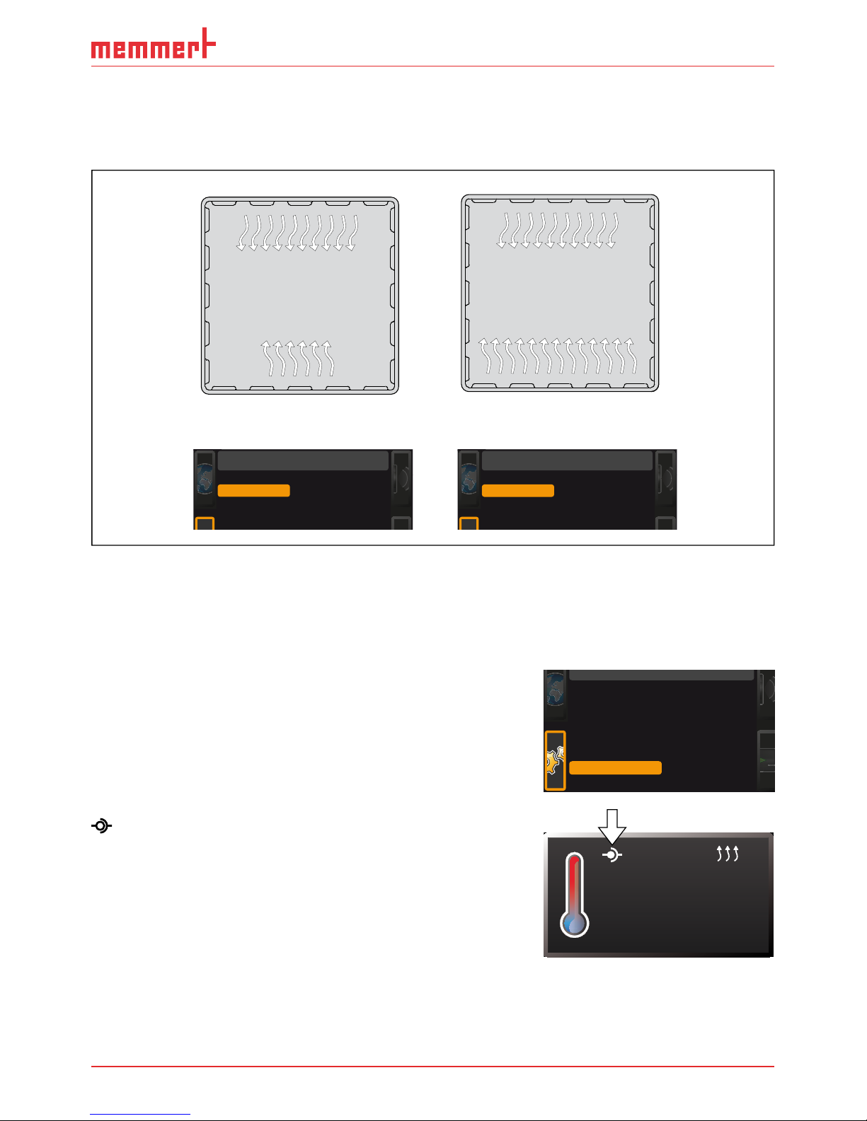
D33340 | Date 08/2017 45
Menu functions
7.3.7 Balance
For appliances of the size 55 and above, application-specific correction of the heat output distribution (balance) between the upper and lower heating groups is possible. The adjustment
range is from –50 % to +50 %.
upper heat output
upper heat output
lower heat output
-20%
lower heat output
+30%
SETUP
Balance
-20 %
2/2
SETUP
Balance
+30 %
2/2
Fig. 27 Heat output distribution (example): The –20 % (left) setting causes the lower heating
groups to emit 20 % less heat than the upper ones. The +30 % (right) setting causes the lower
heating groups to emit 30 % more heat than the upper ones. The 0 % setting restores the
default heat output distribution.
7.3.8 Remote control
In the setup entry Remote control, you can set whether the
appliance should be controlled via remote control. These
settings are available:
► Off
► Read Only
When the appliance is in remote control mode, the
symbol appears in the temperature display.
Setup
Balance
Remote Control Off
Gateway 192.168.5 .1
+30 %
2/2
23.2°C
TEMP
Set 38
.0°C
Page 46
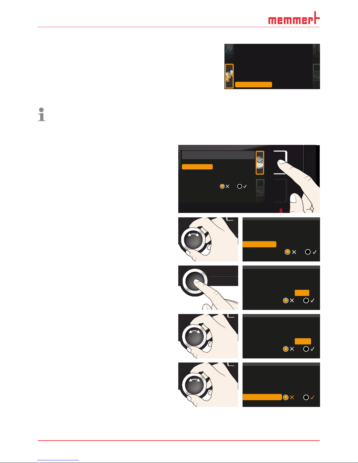
46 D33340 | Date 08/2017
Menu functions
7.3.9 Gateway
The setup entry Gateway is used to connect two networks
with different protocols.
The gateway is set the same way as the IP address (see
page 42).
7.4 Date and Time
In the Time display, you can set date and time, time zone and daylight saving time.
Always set the time zone (and summer time yes/no) before you set the date and time.
Avoid changing the set time after that since this can lead to gaps or overlapping when
recording measured values. If you still need to change the time, you should not run a
programme immediately before or after doing so.
1. Activate the time setting. To do so, press
the activation key on the right side of
the
Time display. The display is enlarged
and the first adjustment option (
Date)
automatically highlighted.
Date and time
Time
Time zone
Daylight savings
12.05.2012
12:00
GMT 01:00
Date
2. Turn the turn control until Time zone is
highlighted.
Time
Daylight savings
12.05 . 2012
12:00
GMT 01:00
Date
Time zone
3. Accept the selection by pressing the
confirmation key.
Time
Daylight savings
12.05 . 2012
12:00
GMT
Date
Time zone
01:00
4. Set the time zone of the installation site
with the turn control, e.g. 00:00 for
France, Spain or Great Britain, 01:00 for
Germany. Accept the selection by pressing the confirmation key.
Time
Daylight savings
12.05 . 2012
12:00
GMT
Date
Time zone
00:00
5. With the turn control, select the Daylight
savings entry
Time
12.05 . 2012
12:00
GMT 00:00
Date
Time zone
Daylight savings
Balance
Remote Control Off
Gateway 192.168.5 .1
+30 %
2/2
Page 47
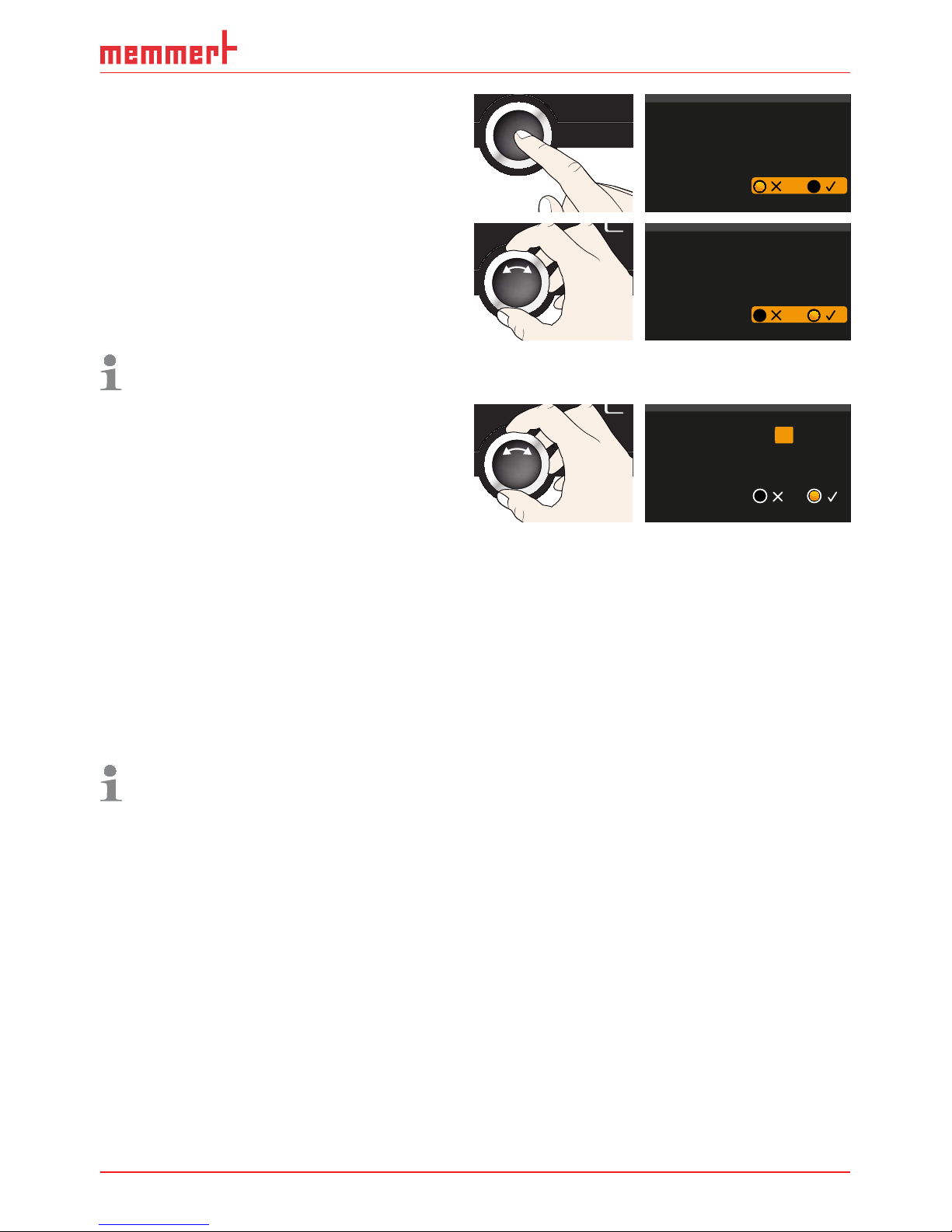
D33340 | Date 08/2017 47
Menu functions
6. Accept the selection by pressing the
confirmation key. The adjustment options
are highlighted.
Time
12.05 . 2012
12:00
GMT 00:00
Date
Time zone
Daylight savings
7. Set daylight savings to off () or on
(
) with the turn control – in this case
on (
). Save the setting by pressing the
confirmation key.
Time
12.05 . 2012
12:00
GMT 00:00
Date
Time zone
Daylight savings
Daylight saving time and standard time are not changed automatically. For this reason,
please keep in mind to adjust them at the beginning of each period.
8. Now, set date (day, month year) and time
(hours, minutes) in the same way. Accept
the selection by pressing the confirmation key.
Time
Time zone
Daylight savings
..2012
12:00
GMT 00:00
Date 27 05
7.5 Calibration
The appliances are temperature calibrated and adjusted at the factory. In case readjustment
should be necessary later on – for example due to influence of the chamber load – the appliance can be calibrated customer-specifically using three calibration temperatures of your
choice:
► Cal1 Temperature calibration at low temperature
► Cal2 Temperature calibration at medium temperature
► Cal3 Temperature calibration at high temperature
To guarantee perfect control, we recommend to calibrate the appliance once a year.
For temperature adjustment, you will need a calibrated reference measuring device.
Page 48

48 D33340 | Date 08/2017
Menu functions
CAL 1
+0,5 K
CAL 3
-0,8 K
CAL 2
+2,6 K
180°C
40°C
120°C
0°C
factory calibration
Fig. 28 Schematic example of temperature adjustment
Example: Temperature deviation at 120 °C should be corrected.
1. Activate the adjustment setting. To do so,
press the activation key on the right side
of the
CALIB display. The display is en-
larged and the first calibration temperature – in this case 40 °C – automatically
highlighted.
Cal1
°C -0,2
K
Cal2 100.0 °C +0,1K
Cal3 180.0 °C -0,2K
JUSTIEREN
Temperatur
letzte Justierung 12.10.2012 12:00
40.0
CK0,2-
CK0,1+
CK0,2-
Calibration
Temperature
Last updated 12.10.2012 12:00:00
Cal1
Cal2
Cal3
100.0
180.0
40.0
2. Press the confirmation key repeatedly,
until the calibration temperature Cal2 is
selected.
CK0,2-
CK0,1+
CK0,2-
Temperature
Cal1
Cal2
Cal3
180.0
40.0
100.0
3. With the turn control, set the calibration
temperature Cal2 to 120 °C.
CK0,2-
CK0,1+
CK0,2-
Temperature
Cal1
Cal2
Cal3
180.0
40.0
120.0
4. Save the setting by pressing the confirmation key. The corresponding calibration value is automatically highlighted.
CK0,2-
CK
CK
0,2-
Temperature Cal1
Cal2
Cal3
180.0
40.0
120.0 0,1+
Page 49

D33340 | Date 08/2017 49
Menu functions
5. Set the calibration value to 0.0 K and accept the setting by pressing the confirmation key.
CK0,2-
CK
CK
0,2-
Calibration
Temperature
Cal1
Cal2
Cal3
180.0
40.0
120.0 0,0
6. Position the sensor of a calibrated reference instrument centrally in the appliance's working chamber.
7. Close the door and, in manual mode,
adjust the set temperature to 120 °C.
21.4°C
TEMP
120.0 °CSet
8. Wait until the appliance reaches the set
temperature and displays 120 °C. The
reference instrument for example displays
122.6 °C.
120.0°C
TEMP
Set 120
.0°C
122.6 °C
9. In the SETUP, adjust the calibration value
Cal2 to +2.6 K (actual value measured
minus setpoint temperature) and save the
setting by pressing the confirmation key.
CK0,2-
CK
CK
0,2-
Temperature
Cal1
Cal2
Cal3
180.0
40.0
120.0 2,6+
10. After the calibration procedure, the
temperature measured by the reference
instrument should now also be 120 °C.
120.0°C
TEMP
Set 120
.0°C
120.0 °C
With Cal1, a calibration temperature below Cal2 can be programmed accordingly, and with
Cal3, a temperature above. The minimum difference between the Cal values is 20 K.
If all calibration values are set to 0.0 K, the factory calibration settings are restored.
Page 50

50 D33340 | Date 08/2017
Menu functions
7.6 Programme
In the PROG display, you can transfer programmes created using AtmoCONTROL software
and saved on a USB storage medium to the appliance. Here, you can also select the programme to be used in manual mode (see page 30) and delete programmes.
To load a programme from a USB storage medium : Connect the USB storage
medium with the saved programme(s)
to the interface on the right side of the
control panel.
1. Activate the programme display. To do so,
press the activation key on the left side of
the
PROG display. The display is enlarged
and the entry
Select automatically
highlighted. The programmes available
for activation are shown on the right. The
programme currently available for use –
in this example
Test 012 – is highlighted
in orange.
Program
Delete
Test 012
Test 013
Test 014
Test 015
Test 017
Test 016
Select
2. Call the Select function by pressing
the confirmation key. All programmes
available are displayed, including the
ones saved on the USB storage medium
(identified by the USB symbol). The
programme currently available for use is
highlighted in orange.
Select
Delete
Test 012
Test 022
Test 013
Test 014
Test 022
3. With the turn control, select the programme you want to make available for
use.
Select
Delete
Test 012
Test 022
Test 013
Test 014
Test 023
4. Accept the selection by pressing the
confirmation key. The programme is now
loaded, which is indicated by the transfer
symbol.
Select
Delete
Test 012
Test 022
Test 013
Test 014
Test 023
5. As soon as the programme is ready, the
selection returns to
Select. To start the
programme: Return to manual mode by
pressing the MENU key and start programme as described on page 30.
Delete
Test 012
Test 022
Test 013
Test 014
Test 015
Test 023
Select
You can now remove the USB storage medium.
To delete a programme, select
Delete with the turn control and select the programme to be
deleted the same way you can select a programme for activation.
Page 51

D33340 | Date 08/2017 51
Menu functions
7.7 Sound
In the SOUND display, you can define whether or not the appliance should emit acoustic
signals and, if yes, define on which events it should do so:
► on the press of a key
► at the end of a programme
► on alarm
► if the door is open
1. Activate the acoustic signal adjustment.
To do so, press the activation key on
the left side of the
SOUND display. The
display is enlarged. The first category (in
this case
Key sound) is automatically
highlighted. On the right, the current settings are shown on.
Sound
Keysound
At the end
If door open
On alarm
If you want to edit another list entry: Turn
the turn control until the respective entry
– e.g.
If door open (Special accessories) –
is highlighted in colour.
Keysound
At the end
If door open
On alarm
Sound
2. Save the selection by pressing the confirmation key. The adjustment options are
automatically highlighted.
Keysound
At the end
If door open
On alarm
Sound
3. With the turn control, select the desired
setting – in this example OFF () .
Keysound
At the end
If door open
On alarm
Sound
4. Save the setting by pressing the confirmation key.
If an acoustic alarm sounds, it can be
turned off by pressing the confirmation
key.
Keysound
At the end
If door open
On alarm
Sound
Page 52

52 D33340 | Date 08/2017
Menu functions
7.8 Protocol
The appliance continually logs all relevant measured values, settings and error messages at
1-minute intervals. The internal log memory is of the continuous memory type. The logging
function cannot be switched off and is always active. The measured data are stored in the
appliance, safe from manipulation. If the power supply is interrupted, the time of the power
failure and voltage recovery are stored in the appliance.
You can export the protocol data for different periods to a USB storage medium via the USB
interface or, via Ethernet, import them to the AtmoCONTROL software for graphical representation, print-out or storage.
The log memory of the appliance is not modified or deleted by reading it out.
1. Connect the USB storage medium to the
interface on the right side of the control
panel.
2. Activate the protocol. To do so, press
the activation key on the right side of
the
PROTOCOL display. The display is
enlarged and the period
This Month au-
tomatically highlighted. To select another
logging period, use the turn control.
Protocol
12.10.2012 12:00
ontrol range
3. Save your selection by pressing the confirmation key. The transfer starts and a
status symbol indicates the progress.
Protocol
This Year
Complete control range
This Month
4. As soon as the transfer is complete, a
check mark appears in front of the period
selected. You can now remove the USB
storage medium.
Protocol
This Year
Complete control range
This Month
For a description of how to import and process protocol data in AtmoCONTROL or
read them out via Ethernet, please observe the separate AtmoCONTROL manual.
Page 53

D33340 | Date 08/2017 53
Menu functions
7.9 User ID
7.9.1 Description
With the User-ID function, you can lock the settings of individual (e.g. temperature) or all
parameters, so that they cannot be changed at the appliance by accident or unauthorised
persons. You can also lock setting options in menu mode (e.g. adjustment or date and time
settings) this way.
If adjustment options are locked, this is indicated by
the lock symbol in the respective display (Fig. 29 ).
User ID data are entered in the AtmoCONTROL
software and saved on the USB storage medium.
The USB storage medium is thus acting as a key:
Parameters can only be locked or unlocked if it is
connected.
A description of how to create a user ID in
AtmoCONTROL is provided in the separate
AtmoCONTROL manual.
7.9.2 User ID activation and deactivation
1. Connect the USB storage medium with
the user ID data to the interface on the
right side of the control panel.
2. Activate the user ID. To do so, press the
activation key on the right side of the
USER-ID display. The display is enlarged
and the entry
Activate automatically
highlighted.
USER-ID
Deactivate
Activate
3. Confirm the activation by pressing the
confirmation key. The new user ID data
are transferred from the USB storage
medium and activated. As soon as activation is complete, a check mark appears in
front of the corresponding entry.
USER-ID
Deactivate
Activate
4. Remove the USB storage medium. Locked parameters are indicated by the lock symbol in
the respective display (Fig. 29 ).
To unlock the appliance, connect the USB storage medium, activate the
USER-ID entry and
select
Deactivate.
22.4
TEMP
°C
°
Fig. 29 Temperature adjustment
at appliance locked (example)
Page 54

54 D33340 | Date 08/2017
Sterilisers SFplus/SNplus
8. Notes on sterilisation
8.1 Contraindications / unwanted side effects
Since hot air sterilisers don’t have a direct therapeutic intended use, the aspects of contraindication and unwanted side effects are not relevant.
8.2 Note in accordance with Medical Devices Directive
The product lifetime as intended by the manufacturer is eight years.
8.3 Guidelines for sterilisation
For hot air sterilisation, there are different guidelines on the temperature and sterilisation time
to choose, as well as on packaging the sterilisation load. The values to be chosen depend on
the type and characteristics of the load to be sterilised and on the type of germs to be neutralised. Before beginning sterilisation, make yourself familiar with the sterilisation method laid
down for your application.
Process parameters for hot air sterilisers are temperature and minimum hold time. The following process parameters have been defined in recognised standards:
► According to WHO: 180 °C with a minimum hold time of 30 min
► According to the European Pharmacopoeia: 160 °C with a minimum hold time of 120 min
For the inactivation of endotoxin (pyrogenes), dry heat of at least 180 °C can be applied. For
the depletion of pyrogenic substances, you have to keep a combination of temperature and
time going beyond the requirements of sterilisation.
Inactivation of endotoxin is possible using the following process parameters (data in accordance with EN ISO 20857:2013):
► 180 °C with a minimum effective time of 180 min
► 250 °C with a minimum effective time of 30 min
Caution:
The temperature and time requirements normal for hot air sterilisation do not destroy
endotoxins.
Especially when the appliance is heavily loaded, using these parameters without checking
them will not be sufficient. For safe sterilisation, validation of the individual sterilisation process is required. The requirements for the validation of sterilisation by dry heat are e.g. defined
in standard EN ISO 20857:2013. Also valuable is the "guideline on validation and routine
monitoring of sterilisation processes using dry heat for medical products" issued by the German Society for Hospital Hygiene (DGKH).
Page 55

D33340 | Date 08/2017 55
Maintenance and service
9. Maintenance and service
9.1 Cleaning
Warning!
Danger due to electric shock. Before doing any maintenance
work, pull out the mains plug.
Warning!
In case of appliances of a certain size, you can get accidentally
locked in, which is life-threatening. Do not climb into the appliance!
Caution!
Danger of cuts due to sharp edges. Always wear gloves when working in the chamber interior.
9.1.1 Working chamber and metal surfaces
Regular cleaning of the easy-to-clean working chamber prevents build up of material remains
that could impair the appearance and functionality of the stainless steel working chamber
over time.
The metal surfaces of the appliance can be cleaned with normal stainless steel cleaning
agents. Make sure that no rusty objects come into contact with the working chamber or with
the stainless steel housing. Rust deposits can lead to an infection of the stainless steel. If rust
spots should appear on the surface of the working chamber due to impurities, the affected
area must be immediately cleaned and polished.
9.1.2 Plastic parts
Do not clean the ControlCOCKPIT and other plastic parts of the appliance with caustic or
solvent-based cleaning agents.
9.1.3 Glass surfaces
Glass surfaces can be cleaned with a commercially available glass cleaner.
9.2 Regular maintenance
Once a year, grease the moving parts of the doors (hinges and lock) with thin silicone grease
and check that the hinge screws are not loose.
To guarantee perfect control, we recommend to calibrate the appliance once a year (see page
47).
9.3 Repairs and service
Warning!
After removing covers, live parts may be exposed. You may
receive an electric shock if you touch these parts. Disconnect
the mains plug before removing any covers. Any work inside
the appliance may only be performed by qualifi ed electri-
cians.
Repairs and service work are described in a separate service manual.
Page 56

56 D33340 | Date 08/2017
Storage and disposal
10. Storage and disposal
10.1 Storage
The appliance may only be stored under the following conditions:
► in a dry and enclosed, dust-free room
► frost-free
► disconnected from the power supply
10.2 Disposal
This product is subject to the Directive 2002/96/EC on Waste
Electrical and Electronic Equipment (WEEE) of the European Parliament
and of the Council. This appliance has been brought to market after
August 13
th
, 2005 in countries which have already integrated this
directive into their national laws. It may not be disposed of in normal
household waste. For disposal, please contact your dealer or the
manufacturer. Any appliances that are infected, infectious or contaminated with materials hazardous to health are excluded from return.
Please also observe all other regulations applicable in this context.
Before disposing of the appliance, please render the door locking
mechanism unusable, for example, to prevent playing children from
being locked inside the appliance.
There is a lithium battery in the ControlCOCKPIT of the appliance.
Remove it and dispose of it in accordance with the regulations in your
country (Fig. 30).
Fig. 30 Removing the lithium battery
Page 57

D33340 | Date 08/2017 57
Index
Index
A
Accessories 16
Acoustic signals 47
Activation key 27
Adjustment 47
Air flap position 28
Air supply 11
Alarm 34, 37
Ambient conditions 15, 16
Ambient temperature 15
Anlieferung 59
Appliance error 38
ASF 32, 34
AtmoCONTROL 3, 12, 16, 27,
30, 50, 52, 53
Automatic temperature
monitor 33
B
Basic device settings 40
Basic settings 40
C
CALIB 48
Calibration 47
Carrying 17
Cause of errors 38
Chamber load 25
Changes 8
Cleaning 55
Clock time 46
Communication interfaces
12
Compensation correction
value 49
Connections 12
ControlCOCKPIT 10, 26
Convection 11
Customer service 2
D
Declaration of conformity 15
Decommissioning 56
Delete programme 50
Delivery 17, 18, 23, 54
Digital backwards counter
29
Dimensions 15
Disposal 56
Door 24
E
Electrical connection 12
Electronic temperature moni-
toring 33
Emergency 9
Ending operation 36
End of programme 31
Error description 38
Error messages 37
Ethernet 12
Explosion protection 8
F
factory calibration settings
49
Fan speed 28
Fehlermeldung 39
Forklift truck 18
Function 11
G
Gateway 46
Graph 36
Grid 44
H
Hazards 7
Heat output distribution 45
I
Inbetriebnahme 59
Installation site 19
Intended use 8
Interfaces 12
Interior lighting 28
IP address 42
L
Language selection 41
Lighting 28
Loading the appliance 25
Log memory 39, 52
M
Maintenance 55
Malfunctions 9, 37
Manufacturer 2
Material 11
Mechanical temperature
monitoring 34
Medical Devices Directive 54
Menu 40, 46
Minimum clearances 19
Monitoring temperature 32
N
Nameplate 13
Network 12, 42
Normal mode 27, 28
O
Operating 24
Operating modes 27
Operating personnel 7, 24
Operating problems 38
Operation 24
P
Packaging material 18
Power failure 39
Power supply 52
Press of a key 51
Product safety 7
Programme 50
Programme mode 27, 30
Pt100 temperature sensor
32
Putting into operation 23,
54
R
Rectifying errors 38
Regular maintenance 55
Remote control 45
S
Safety regulations 6
Service 55
Servicing 55
Setting parameters 27, 41
Setting up 17, 19
Setting up options 20
Setup 42
Shelf 44
Slide-in unit 44
Speaker symbol 37
Sterilisatoren 59
Sterilisers 24, 54
Storage after delivery 18
Switching off 36
Switching on 23
Page 58

58 D33340 | Date 08/2017
Index
T
TB 34
Technical data 14
Temperature 28
Temperature comparison 47
Temperature deviation 48
Temperature limiter 34
Temperature monitor 32, 34
Temperature monitoring 31,
32, 43
Temperature sensor 32
Tilt protection 21
Time 44
Timer 29
Timer mode 44
Transport 17, 18
Transport damage 18
Türen einstellen 22
Turn control 27
TWB 33
TWW 33
TWW temperature monitor-
ing 33
U
Unit 43
Unpacking 18
USB interface 12, 52
User ID 53
W
Warning messages 12, 37
Weight 14
Page 59

59
Appendix
Appendix
T
Technical description according to EN 60601-1-2
EMC-Guidance
Operation Manual Appendix
Steriliser
SNxx, SFxx, SNxxplus, SFxxplus
Page 60
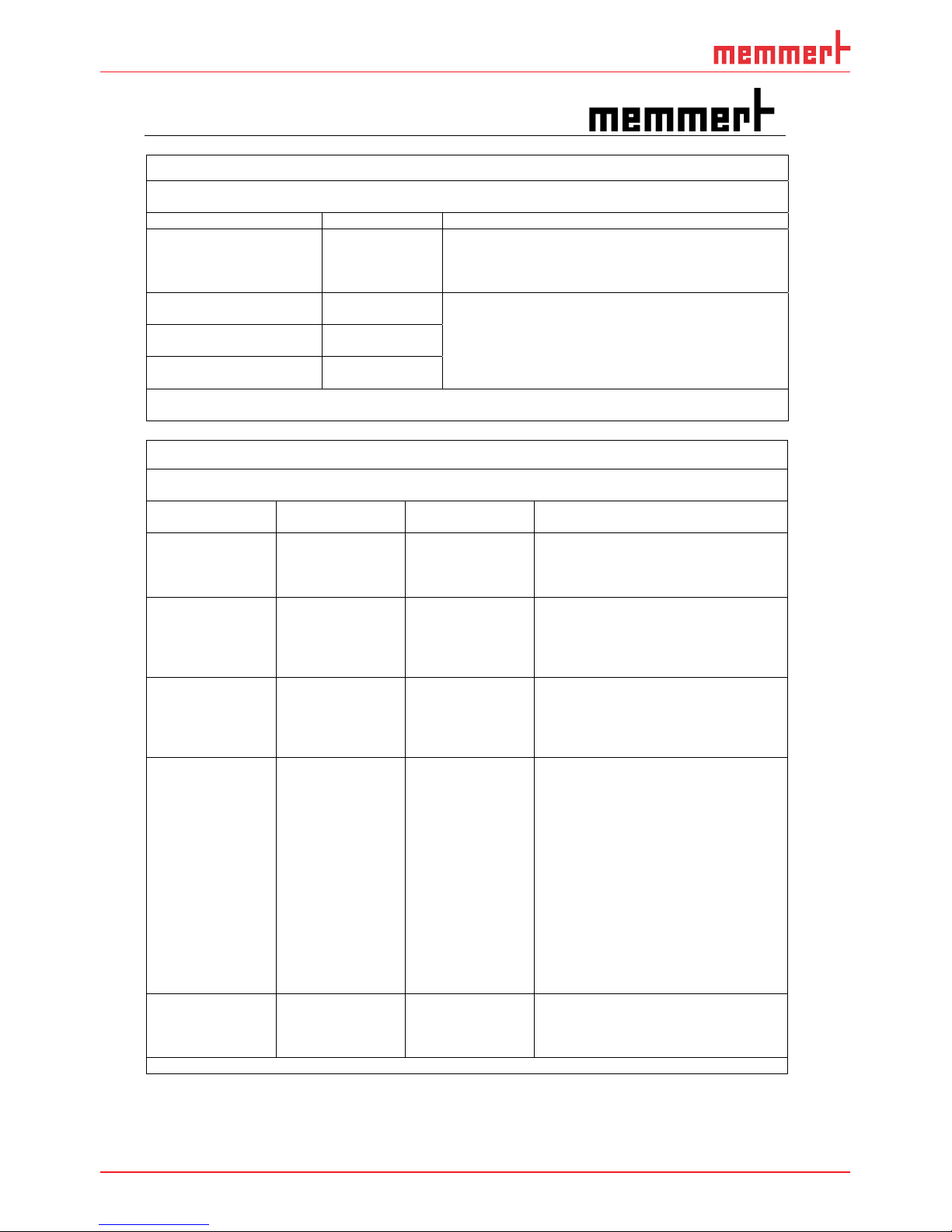
60
Appendix
T
Technical description according to EN 60601-1-2
Guidance and manufacturer’s declaration – electromagnetic emissions
The Memmert steriliser type S.. is intended for use in the electromagnetic environment specified below. The
customer or user of the steriliser type S.. should assure that it is used in such an environment.
Emissions test Compliance Electromagnetic environment - guidance
RF emissions
CISPR 11
Group 1 The steriliser type S.. uses RF energy only for ist internal
function. Therefore, ist RF emissions are very low and are
not likely to cause interference in nearby electronic
equipment.
RF emissions
CISPR 11
Class B The sterilier type S.. is suitable for use in all
establishments, including domestic establishments and
those directly connected to the public low-voltage power
supply network that supplies buildings used for domestic
purposes.
Harmonic emissions
IEC 61000-3-2
Class A
Volage fluctuations / flicker
emissions IEC 61000-3-3
Complies
NOTE The system impedance at the interface point according to IEC 61000-3-11 should not ecxeed
0.248+j0.155 Ohm resp. Zsys = 0.29 Ohm.
Guidance and manufacturer’s declaration – electromagnetic immunity
The Memmert steriliser type S.. is intended for use in the electromagnetic environment specified below. The
customer or user of the steriliser type S.. should assure that it is used in such an environment.
Immunity
test
IEC 60601
test level
Compliance
level
Electromagnetic enviroment –
guidance
Electrostatic
discharge (ESD)
IEC 61000-4-2
r 6 kV contact
r 8 kV air
r 6 kV contact
r 8 kV air
Floors should be wood, concrete or
ceramic tile. If floors are covered with
synthetic material, the relative humidity
should be at least 30 %.
Electrical fast
tranient / burst
IEC 61000-4-4
r 2 kV for power
supply lines
r 1 kV for input /
output lines
r 2 kV for power
supply lines
r 1 kV for input /
output lines
Mains power quality should be that of a
typical commercial or hospital
enviroment.
Surge
IEC 61000-4-5
r 1 kV differential
mode
r 2 kV common
mode
r 1 kV differential
mode
r 2 kV common
mode
Mains power quality should be that of a
typical commercial or hospital
enviroment.
Voltage dips, short
interruptions and
voltage variations
on power supply
input lines
IEC 61000-4-11
< 5 %
U
T
(>95 % dip in
U
T
)
for 0,5 cycle
40 %
U
T
(60 % dip in
U
T
)
for 5 cycles
70 %
U
T
(30 % dip in
U
T
)
for 25 cycles
< 5 %
U
T
(>95 % dip in
U
T
)
for 5 s
< 5 %
U
T
(>95 % dip in
U
T
)
for 0,5 cycle
40 %
U
T
(60 % dip in
U
T
)
for 5 cycles
70 %
U
T
(30 % dip in
U
T
)
for 25 cycles
< 5 %
U
T
(>95 % dip in
U
T
)
for 5 s
Mains power quality should be that of a
typical commercial or hospital
enviroment.
If the user of the steriliser type S..
requires continued operation during
power mains interruptions, it is
recommended that the steriliser type S..
will be powered from an uninterruptible
power supply.
Power frequency
(50/60 Hz)
magnetic field
IEC 61000-4-8
3 A/m Not applicable
NOTE
U
T
is the mains voltage prior to application of the test level.
Page 61
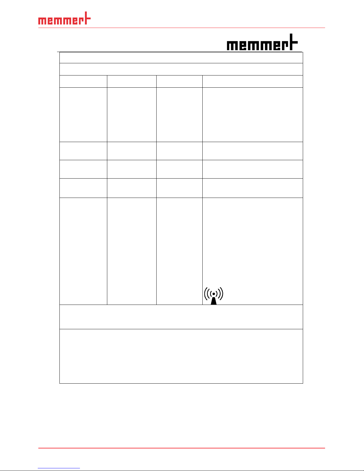
61
Appendix
T
Technical description according to EN 60601-1-2
Guidance and manufacturer’s declaration – electromagnetic immunity
The Memmert steriliser type S.. is intended for use in the electromagnetic environment specified below.
The customer or user of the steriliser type S.. should assure that it is used in such an environment.
Immunity
test
IEC 60601
test level
Compliance
level
Electromagnetic enviroment –
guidance
Portable and mobile RF communications
equipment should be used no closer to any
part of the steriliser type S.., including
cables, than the recommended seperation
distance calculated from the equation
applicable to the frequency of the
transmitter.
Recommended separation distance
Conducted RF
IEC 61000-4-6
3 V
rms
150 kHz bis 80 MHz
3 V
rms
d
= 1,2
P
Radiated RF
IEC 61000-4-3
3 V/m
80 MHz bis 2,5 GHz
3 V/m
d
= 1,2 P 80 MHz to 800 MHz
d
= 2,3
P
800 MHz to 2,5 GHz
where
P
is the maximum power rating of
the transmitter in watts (W) according to
the transmitter manufacturer and
d
as the
recommended separtion distance in
metres (m).
Field strengths from fixed RF transmitters,
as determined by an electromagnetic site
survey,
a
should be less than the
compliance level in each frequency range.
b
Interference may occur in the vicinity of
equipment marked with the following
symbol:
NOTE 1 At 80 MHz and 800 MHz, the higher frequency range applies.
NOTE 2 These guidelines may not apply in all situations. Electromagnetic propagation is affected by
absorption and reflection from structures, objects and poeple.
a Field strengths from fixed transmitters, such as base stations for radio (cellular/cordlass) telephones
and land mobile radios, amateur radio, AM and FM radio broadcast and TV broardcast cannot be
predicted theoretically with accuracy. To assess the electromagnetic enviroment due to fixed RF
transmitters, an electromagnetic site survay should be considered. If the measured field strength in the
location in which the steriliser type S.. is used exceeds the applicable RF compliance level above, the
Steriliser type S.. should be observed to verify normal operation. If abnormal performance is observed,
addidional measures may be necessary, such as re-orienting or relocating the steriliser type S..
b
Over the frequency range 150 kHz to 80 MHz, field strengths should be less than 3 V/m.
Page 62

62
Appendix
T
Technical description according to EN 60601-1-2
Recommended separation distances between portable and mobile
RF communications equipment and the Memm
ert steriliser type S..
The steriliser type S.. is intended for use in electromagnetic enviroment in which radiated RF disturbances
are controlled. The customer or of the steriliser type S.. can help prevent electromagnetic interference by
maintaining a minimum distance between portable and mobile RF communications equipment
(transmitters) and the steriliser type S.. as recommended below, according to the maximum power of the
communications equipment.
Rated maximum output
power of trtansmitter
W
Separation distance according to frequency of transmit
ter
m
150 kHz to 80 MHz
d
= 1,2
P
80 MHz to 800 MHz
d
= 1,2
P
800 Mhz to 2,5 GHz
d
= 2,3
P
0,01 0,12 0,12 0,23
0,1 0,38 0,38 0,73
1 1,2 1,2 2,3
10 3,8 3,8 7,3
100 12 12 23
For transmitters rated at a maximum output power not listed above, the recommended separation
distance
d
in metres (m) can be estimated using the equation applicable to the frequency of the
transmitter, whre
P
is the maximum output power rating of the transmitter in watts (W) according to the
transmitter manufacturer.
NOTE 1 At 80 MHz and 800 MHz, the separation distance for the higher frequency range applies.
NOTE 2 These guidelines may not apply in all situations. Electromagnetic propagation is affected by
absorption and reflection from structures, objects and poeple.
Listing of cables and maximum length of cables
Description of terminal Type of cable Maximum length of cable
m
LAN port RJ45 CAT 6 2
Warning! The use of other cables may result in increased emissions or
decr
eased immunity of the Memmert steriliser type S..
Page 63

EC Declaration of Conformity
Manufacturer´s name and address: Memmert GmbH + Co. KG
Äussere Rittersbacherstraße 38
D-91126 Schwabach
Deutschland
Product: Sterilizer Dry Heat, type SNxx/ SFxx/ SNxx plus/ SFxx plus;
UMDNS-No. 18-739
Type: SN…/30/55/75/110/160/260/450/750
SF…/30/55/75/110/160/260/450/750
SN…plus/30/55/75/110/160/260/450/750
SF…plus/ 30/55/75/110/160/260/450/750
Including all accessories
Nominal voltage: AC 230 V or 3 ~ AC 400 V 50 / 60 Hz, alternative AC 115 V
50/60 Hz
Class IIb, According to directive 93/42/EC, annex IX Rule 15 and MEDDEV
2.4/1 Rev. 9 June 2010
We hereby declare the conformity of the above mentioned products with the directive 93/42/EC
annex II, section 3. Above product is designed and manufactured in compliance with the EU directive
93/42/EC.
Notified Body TÜV Rheinland LGA Products GmbH
Tillystr. 2
D-90431 Nürnberg
Germany
Notified Body no. 0197
QS Certificate HD 60106200 0001 valid until 7. December 2020
Declaration of Conformity
Valid until 07. December 2020
The object described in the declaration above corresponds to the directive 2011/65/EC of the
European Parliament and the Council of 8 June 2011on the restriction of the use of certain hazardous
substances in electrical and electronic equipment.
Schwabach, 09.06.2016
(
Legally binding signature of the issuer)
This declaration certifies compliance with the above mentioned directives but does not include a property assurance.
The safety note given in the product documentation which are part of the supply, must be observed.
Page 64

Memmert GmbH + Co. KG
Willi-Memmert-Straße 90-96 | D-91186 Büchenbach
Tel. +49 9122 925-0 | Fax +49 9122 14585
E-Mail: sales@memmert.com
facebook.com/memmert.family
Die Experten-Plattform: www.atmosafe.net
Sterilisers plus
D33340 | Date 08/2017
englisch
 Loading...