

Page 1
Pump module
00%
O
MANUAL
Appliance sizes
PM/PMP 29
PM/PMP 49
PM/PMP 101
100% ATMOSAFE.MADE IN GERMANY
1
ATM
www.memmert.com I www.atmosafe.net
Page 2

2
About this manual
Purpose and target audience
This manual, together with the operating manual for the MEMMERT vacuum oven, describes
how to use and put into operation the MEMMERT pump module. Pump modules can be purchased with or without a pre-installed vacuum pump.
The manual contains the original maintenance and operating manual for the membrane vacuum pump, which may have been installed, from the company KNF.
The pump module may only be used in combination with the MEMMERT vacuum oven VO or
VOcool. All information in terms of safety instructions, assembly, function, transport, putting
into operation, operation, troubleshooting, maintenance and decommissioning/disposal can be
found in the operating manual for the vacuum oven VO.
This manual is intended for use by trained personnel of the owner, who have the task of operating and/or maintaining the respective appliance. If you are asked to work on the appliance,
read this manual carefully before starting.
Familiarise yourself with the safety regulations. Only perform work that is described in this manual. If there is something you do not understand, or certain information is missing, ask your
manager or contact the manufacturer. Do not do anything without authorisation.
Other documents to be observed as applicable:
► The operating manual for the MEMMERT vacuum oven VO
► The original maintenance and operating manual for the vacuum pump from KNF
Storage and resale
This operating manual belongs with the appliance and should always be stored where persons working on the appliance have access to it. It is the owner's responsibility to ensure that
persons who are working on or are going to work on the appliance know where to find the
operating manual. We recommend that it is always stored in a protected location close to the
appliance. Make sure that the operating manual is not damaged by heat or humidity. If the
appliance is resold or transported and then set up again at a different location, the operating
manual must remain with it.
The current version of this operating manual in PDF format is also available for download from
http://www.memmert.com/en/service/downloads/user-manual/.
MEMMERT GmbH + Co. KG
Willi-Memmert-Straße 90-96
D-91186 Büchenbach
Germany
Phone: +49 (0)9122 925-0
Fax: +49 (0)9122 14585
Email: sales@memmert.com
Internet: www.memmert.com
Customer service:
Hotline: +49 (0)9171 9792 911
Service fax: +49 (0)9171 9792 979
E-mail: service@memmert.com
© 2018 Memmert GmbH + Co. KG
Page 3
Safety regulations
WARNING
After removing covers, live parts may be exposed. Touching these can lead to an
electric shock. Disconnect the mains plug before removing any covers. Work on
the electrical system must only be performed by qualifi ed electricians.
WARNING
Toxic gases or vapours may be produced in certain applications. These
can escape from the vacuum pump into the room. This can injure people
nearby. The appliance may only be used for such applications if a suction
is attached to the vacuum pump used, which reliably keeps toxic gases or
vapours away from people. Observe the respective national regu-lations for
occupational safety and environmental protection.
NOTICE
3
The operating manual of the MEMMERT vacuum oven contains important
information and instructions how to use the pump module. Followall possible information from the related operating manual of the vacuum oven
exactly.
MEMMERT GmbH + Co. KG
Willi-Memmert-Straße 90-96
D-91186 Büchenbach
Germany
Phone: +49 (0)9122 925-0
Fax: +49 (0)9122 14585
Email: sales@memmert.com
Internet: www.memmert.com
Customer service:
Hotline: +49 (0)9171 9792 911
Service fax: +49 (0)9171 9792 979
E-mail: service@memmert.com
© 2018 Memmert GmbH + Co. KG
Page 4
4
Intended use
The appliance may only be used to accommodate and control a vacuum pump by means of a
MEMMERT vacuum oven VO29, VO49 or VO101. Any other use is improper and may result in
hazards and damage.
Changes and alterations
No unauthorised changes or alterations may be made to the appliance. No parts may be added
or inserted which have not been approved by the manufacturer.
Unauthorised changes or alterations result in the CE declaration of conformity losing its validity,
and the appliance may no longer be operated.
The manufacturer is not liable for any damage, danger or injuries that result from unauthorised
changes or alterations, or from non-compliance with the provisions in this manual.
Requirements of the operating personnel
The appliance may only be operated and maintained by persons who are of legal age and have
been instructed accordingly. Personnel who are to be trained, instructed or who are undergoing general training may only work with the appliance under the continuous supervision of an
experienced person.
Repairs may only be performed by qualified specialists. The provisions in the operating and
installation manual from KNF also need to be observed.
Behaviour in case of malfunctions and irregularities
The appliance may only be used in a flawless condition. If you as the operator notice irregularities, malfunctions or damage, immediately take the appliance out of service and inform your
superior.
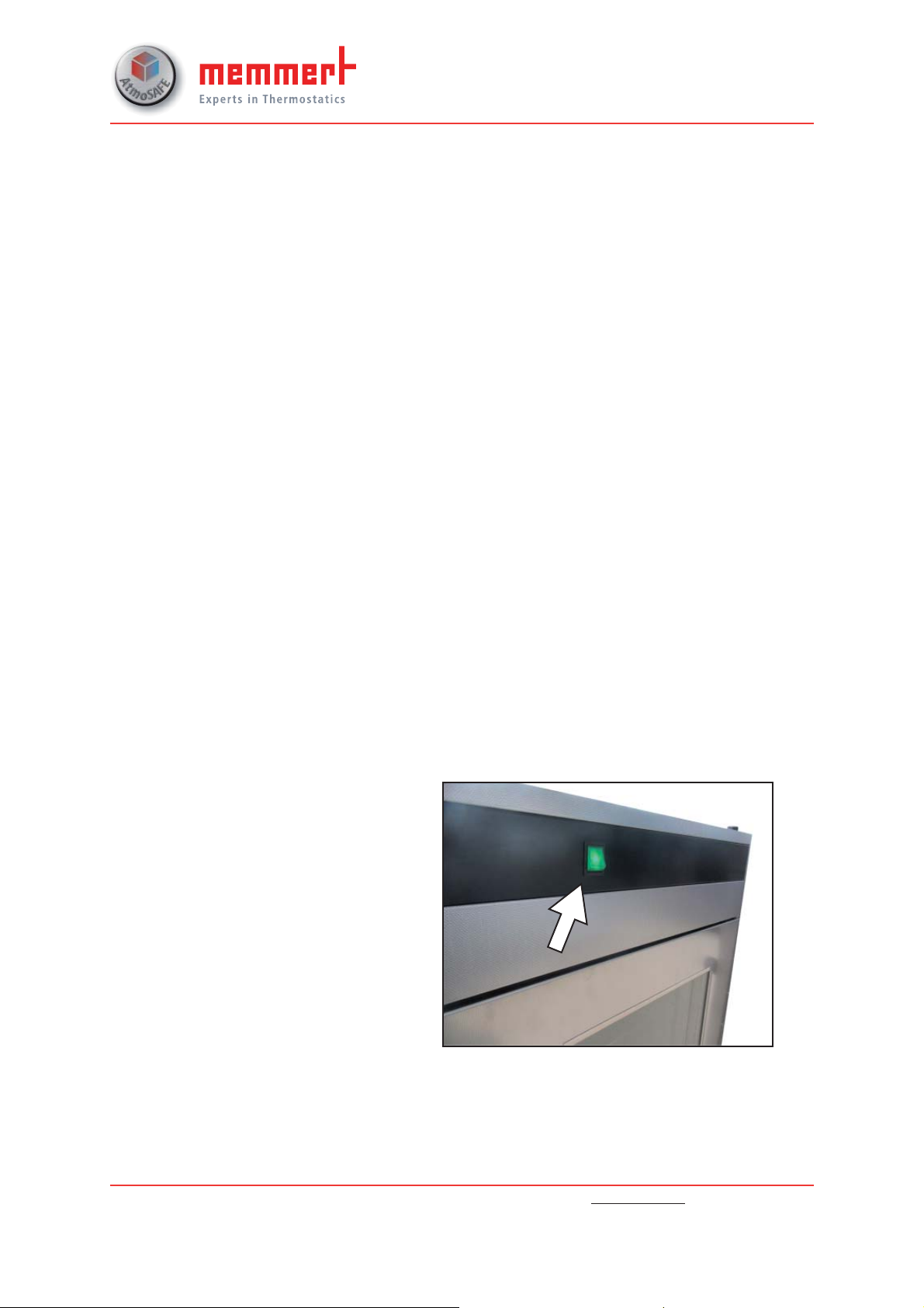
Switching off the appliance in
an emergency
Press the main switch on the pump module.
This disconnects the appliance from the
power supply at all poles.
MEMMERT GmbH + Co. KG
Willi-Memmert-Straße 90-96
D-91186 Büchenbach
Germany
Phone: +49 (0)9122 925-0
Fax: +49 (0)9122 14585
Email: sales@memmert.com
Internet: www.memmert.com
Customer service:
Hotline: +49 (0)9171 9792 911
Service fax: +49 (0)9171 9792 979
E-mail: service@memmert.com
© 2018 Memmert GmbH + Co. KG
Page 5
5
Putting into operation
When operating the appliance for the first time, do not leave it unattended until it has reached
a steady state.
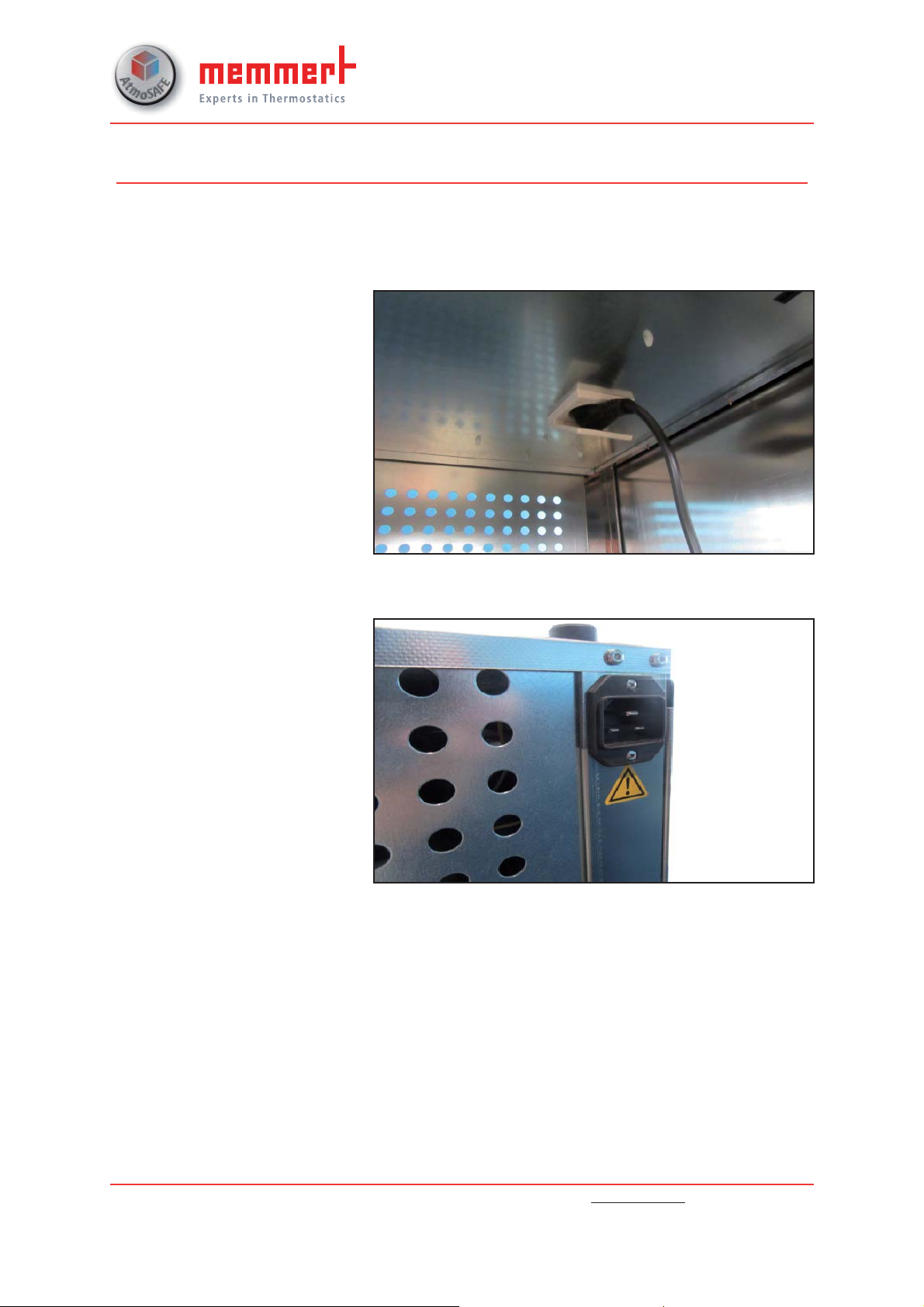
Connecting the vacuum pump
► Connect the vacuum pump's
230 V plug with earthing contact to the internal socket in
the pump module.
Connecting the appliance
Caution:
For connection, please observe
the national regulations. Observe
the connection and power ratings
(see nameplate and technical
data).
Make sure to establish a safe PE
conductor connection.
Place the power cable so that
► it is easily accessible at all times
and can be pulled out quickly,
for example in case of a malfunction or emergency;
► it does not represent a trip
hazard;
► it cannot come into contact
with any hot parts.
MEMMERT GmbH + Co. KG
Willi-Memmert-Straße 90-96
D-91186 Büchenbach
Germany
Phone: +49 (0)9122 925-0
Fax: +49 (0)9122 14585
Email: sales@memmert.com
Internet: www.memmert.com
Customer service:
Hotline: +49 (0)9171 9792 911
Service fax: +49 (0)9171 9792 979
E-mail: service@memmert.com
© 2018 Memmert GmbH + Co. KG
Page 6
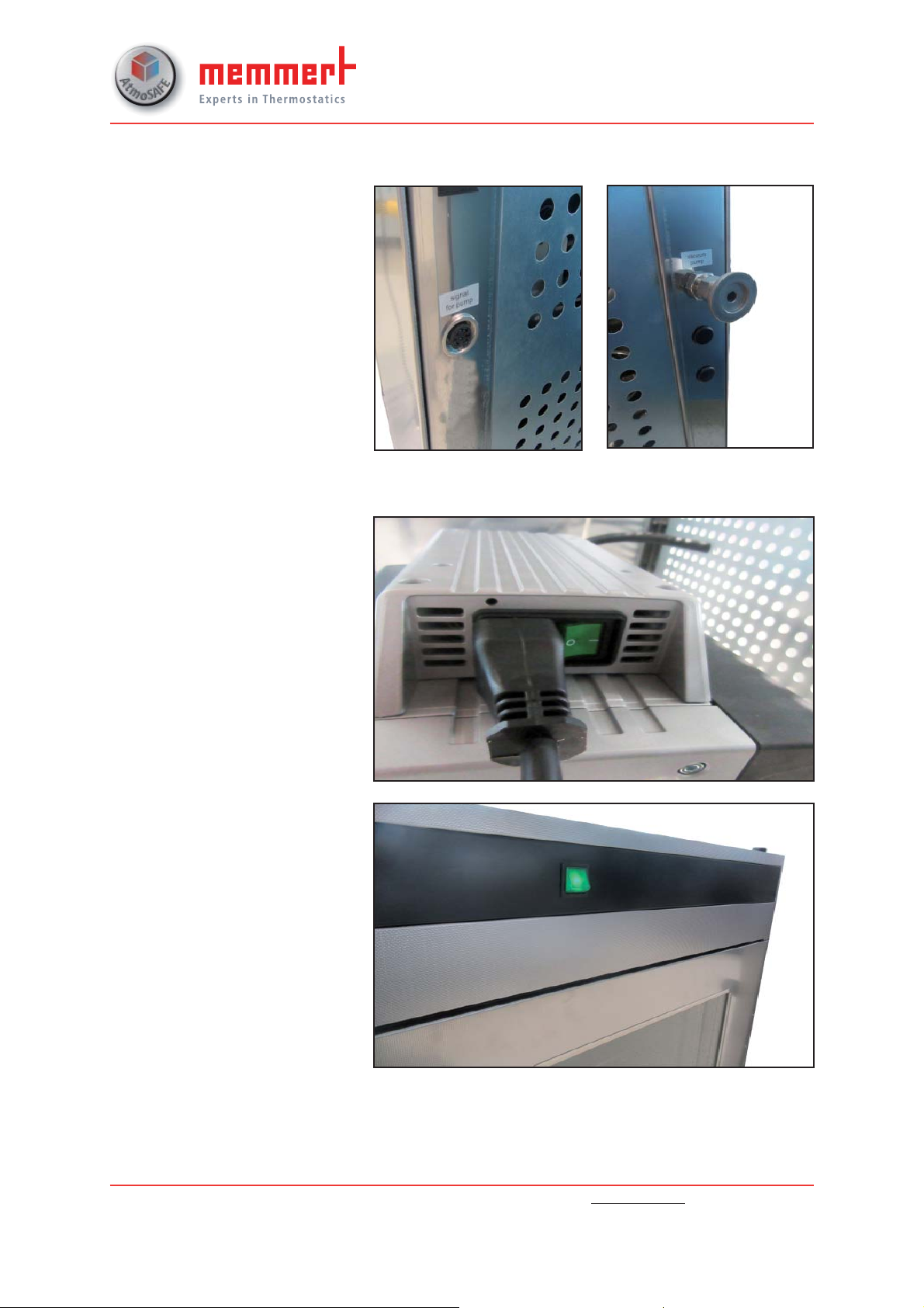
Connecting the vacuum pump to the VO
The connection for the signal lead
(left) and the connection for the
vacuum hose (right) can be found
at the rear of the PM.
Connect the vacuum oven and the
pump module to the signal lead
and the vacuum hose as described
in the operating manual for the
MEMMERT vacuum oven.
Switching on
► Press the main switch for the
vacuum pump.
6
► Press the main switch for the
pump module.
MEMMERT GmbH + Co. KG
Willi-Memmert-Straße 90-96
D-91186 Büchenbach
Germany
Phone: +49 (0)9122 925-0
Fax: +49 (0)9122 14585
Email: sales@memmert.com
Internet: www.memmert.com
Customer service:
Hotline: +49 (0)9171 9792 911
Service fax: +49 (0)9171 9792 979
E-mail: service@memmert.com
© 2018 Memmert GmbH + Co. KG
Page 7
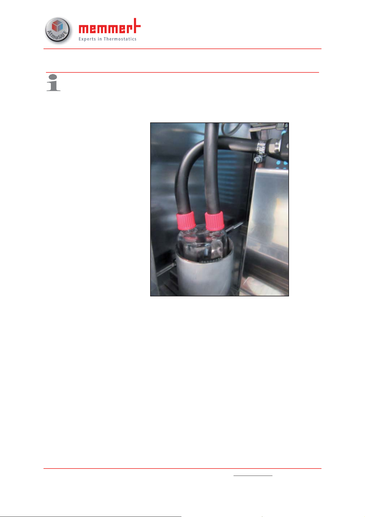
Maintenance and cleaning
Depending on the customer process, condensate may accumulate in the
collection container of the pump module. No condensate can be sucked in
by the pump. Check and empty the container regularly.
Emptying the collection container
► Unscrew and remove the
ducts from the collection
container.
► Remove the collection con-
tainer from the holder and
empty it.
► Insert the collection container
into the holder and attach
the ducts.
7
MEMMERT GmbH + Co. KG
Willi-Memmert-Strasse 90-96
D-91186 Büchenbach
Germany
Phone: +49 (0)9122 925-0
Fax: +49 (0)9122 14585
Email: sales@memmert.com
Internet: www.memmert.com
Customer service:
Hotline: +49 (0)9171 9792 911
Fax: +49 (0)9171 9792 979
Email: service@memmert.com
© 2018 Memmert GmbH + Co. KG
Page 8
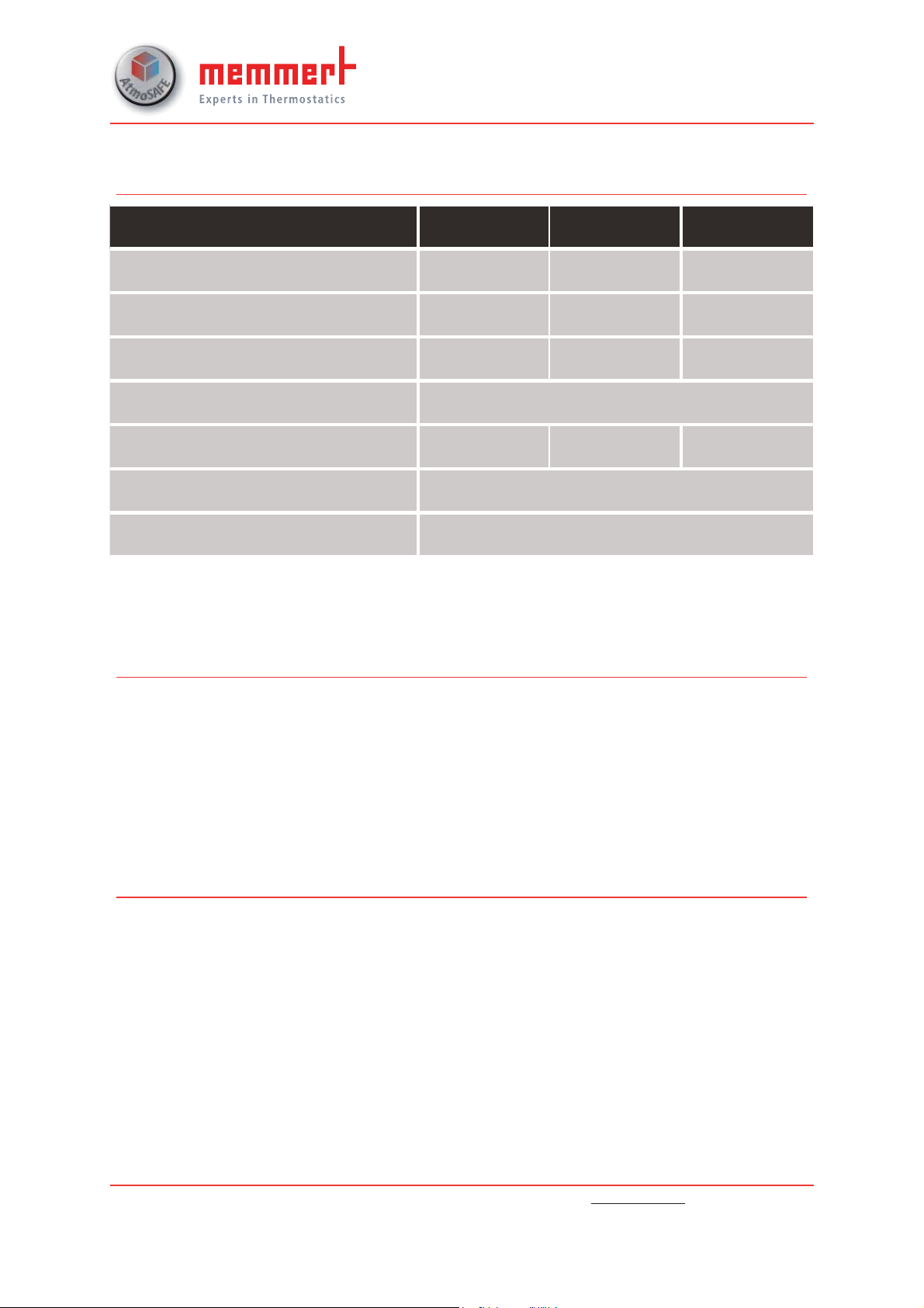
Technical data
Appliance size 29 49 101
Appliance width D [mm] 550 550 710
Appliance height E [mm] 600 680 760
Appliance depth F [mm] 400 480 550
Depth of door lock [mm] 38
Weight without/with pump [kg] 25/33 30/38 41/49
Power [W]* 140
Current consumption [A]* 1.9
8
*All other technical data can be found in the operating and installation manual for the KNF
pump which follows
Spare parts and service
In the event of a malfunction or if the pre-installed membrane vacuum pump requires maintenance or service work, contact the Customer Service department at Memmert.
The spare parts required for complete maintenance of the pump head are available from
Memmert under the following order number:
► E07534 spare parts kit for membrane.
Operating and installation information
Information about the assembly and functionality of the pre-installed KNF vacuum pump
N950.50 KNE-W can be found in the manufacturer's original operating manual (provided).
MEMMERT GmbH + Co. KG
Willi-Memmert-Straße 90-96
D-91186 Büchenbach
Germany
Phone: +49 (0)9122 925-0
Fax: +49 (0)9122 14585
Email: sales@memmert.com
Internet: www.memmert.com
Customer service:
Hotline: +49 (0)9171 9792 911
Service fax: +49 (0)9171 9792 979
E-mail: service@memmert.com
© 2018 Memmert GmbH + Co. KG
Page 9
KNF 125530-316634 06/18
LAB
PJ25481-950.50.18
TRANSLATION OF ORIGINAL INSTALLATION
ENGLISH
INSTRUCTIONS
DIAPHRAGM PUMP
Note!
Before operating the pump and the accessories, please read the operating instructions and pay attention to
the safety precautions!
Page 10

KNF Neuberger GmbH
Alter Weg 3
79112 Freiburg
Germany
Phone +49-(0)7664-5909-0
Fax +49-(0)7664-5909-99
E-mail: info@knf.de
www.knf.de
Contents Page
About this document ................................................................. 3
1.
2. Use............................................................................................ 4
3. Safety ........................................................................................ 6
4. Technical Data .......................................................................... 8
5. Design and function ................................................................ 10
6. Installation and connection ..................................................... 11
7. Operation ................................................................................ 15
8. Servicing ................................................................................. 20
9. Troubleshooting ...................................................................... 28
10. Returns ................................................................................. 300
11. Health and safety clearance and decontamination form ...... 311
Page 11
Diaphragm pump PJ25481-950.50.18 About this document
A danger is located here.
Possible consequences of a failure to observe the
warning are
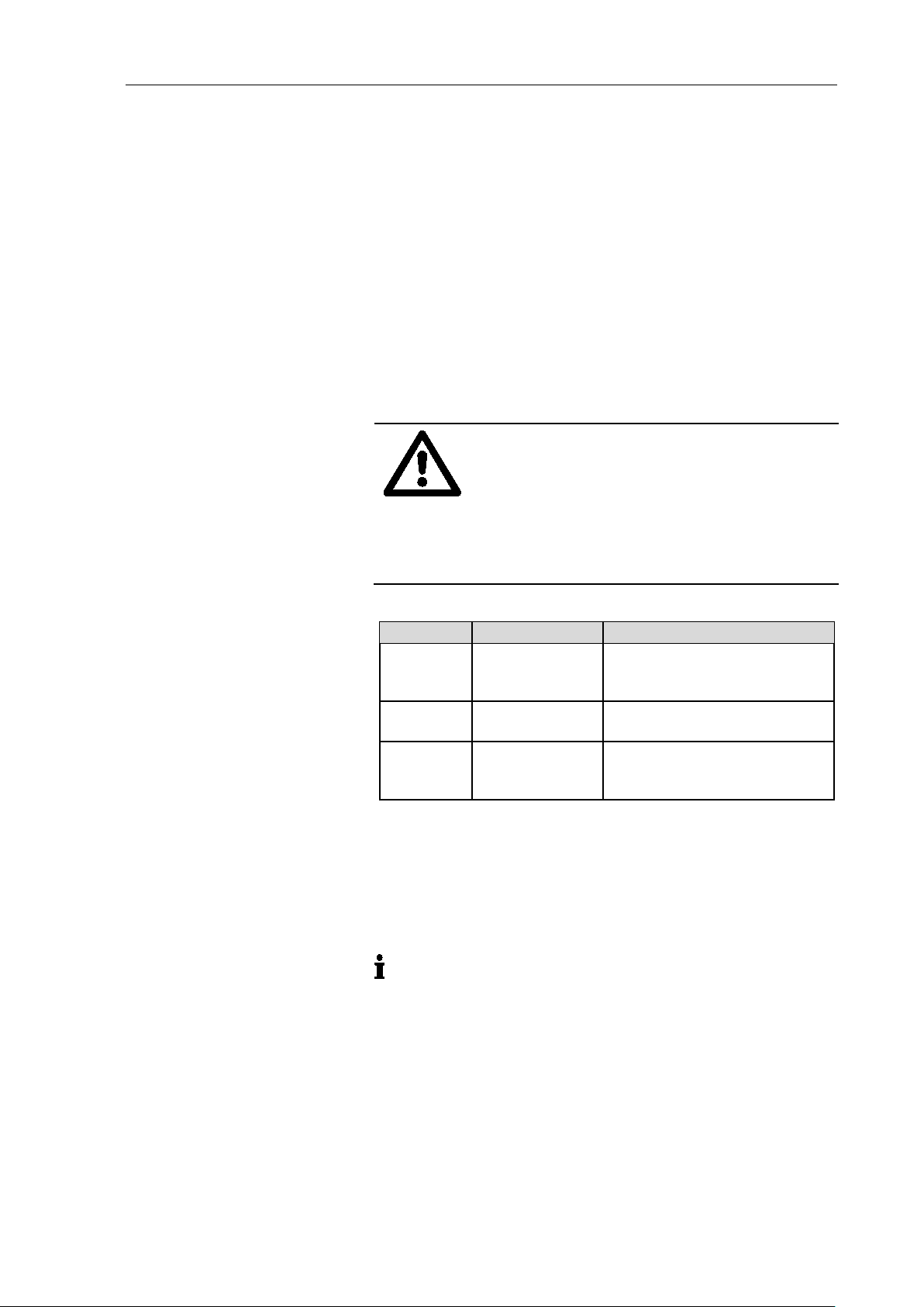
Warning, indicates the danger level.
Signal word
Meaning
Consequences if not observed
DANGER
warns of immedi-
Death or serious injuries and/or
WARNING
warns of possible
Death or serious injuries and/or
CAUTION
warns of a possi-
Minor injuries or damage are
This symbol refers to important inform ation.
1. About this document
1.1. Using the Installation Instructions
The Installation Instructions are part of the pump.
Carefully study the Installation Instructions before using the
pump.
Always keep the Installation Instructions handy in the work
area.
Pass on the Installation Instructions to the next owner.
1.2. Symbols and markings
Warning
WARNING
Measures for avoiding the danger and its conse-
quences are specified here.
Danger levels
ate danger
danger
bly dangerous
situation
Tab. 1
Other information and symbols
An activity to be carried out (a step) is specified here.
1. The first step of an activity to be carried out is specified here.
Additional, consecutively numbered steps follow.
specified here. The signal word, e.g.
serious damage are the consequence.
serious damage are possible.
possible.
Original-Installation Instructions, english, KNF 12553 0-3166 34 06/ 1 8 3
Page 12

Use Diaphragm pump PJ25481-950.50.18
Operating parameter and
Requirements for
Accessories
2. Use
2.1. Proper use
The pumps are exclusively intended for transferring gases and vapors.
Owner’s responsibility
Only install and operate the pumps under the operating parameters
conditions
transferred medium
and conditions described in Chapter 4. Technical Data.
Make sure that the installation location is dry and the pump is pro-
tected against rain, splash, hose and drip water as well as other
pollutions.
The gas-tightness of the connections between the application
pipes and the pump (or the pump connection) must be checked
regularly; with leaky connections, there is a danger that hazardous
gases or vapors may escape from the pump system.
Before using a medium, check whether the medium can be transferred danger-free in the specific application case.
Before using a medium, check the compatibility of the materials of
the pump head, diaphragm and valves with the medium.
Only transfer gases which remain stable under the pressures and
temperatures occurring in the pump.
Laboratory equipment or additional components connected to a
vacuum pump system have to be suitable for use with the pneumatic capabilities of the pump. (see Chapter 4. Technical Data).
4 Translation of original Installation Instructi ons , english, KNF 125530-316634 06/18
Page 13

Diaphragm pump PJ25481-950.50.18 Use
2.2. Improper use
The pumps may not be operated in an explosive atmosphere.
The pumps are not suitable for transferring dusts.
The pumps are not suitable for transferring liquids.
The pumps are not suitable for transferring aerosol.
The pumps are not suitable for transferring biological and microbio-
logical substances.
The pumps are not suitable for transferring fuel.
The pumps are not suitable for transferring explosive and combus-
tible materials.
The pumps are not suitable for transferring fibers.
The pumps are not suitable for transferring oxidizing agent.
The pumps are not suitable for transferring foodstuffs.
The pumps must not be used to create vacuum and overpressure
simultaneously.
Pumps designed to create either a vacuum or an overpressure
must not be used for these two purposes simultaneously.
An overpressure must not be applied to the suction side of the
pump.
Translation of original Installation Instructi ons , english, KNF 125530-316634 06/18 5
Page 14

Safety Diaphragm pump PJ25481-950.50.18
Note the safety precautions in Chapter 6. Installation and connect
Personnel
Working in a safety
Handling dangerous media
Handling combustible media
3. Safety
conscious manner
The pumps are built according to the generally recognized rules of
the technology and in accordance with the occupat io na l saf et y and
accident prevention regulations. Nevertheless, dangers can result
during their use which lead to injuries to the user or others, or to
damage to the pump or other property.
Only use the pumps when they are in a good technical and proper
working order, in accordance with their intended use, observing the
safety advice within the Installation Instructions, at all times.
Components connected to the pump must be designed to withstand the pneumatic performance of the pump.
Take care that safety regulations are observed when connecting
the pump to the electricity supply.
Make sure that only trained and instructed personnel or specially
trained personnel work on the pumps. This especially applies to
assembly, connection and servicing work.
Make sure that the personnel has read and understood the Installation Instructions, and in particular the “Safety” chapter.
Observe the accident prevention and safety regulations when performing any work on the pump and during operation.
ion and 7. Operation.
Do not expose any part of your body to the vacuum.
Ensure that the pump is separated from the mains and is de-ener-
gized.
The pump heads heat up during operation – avoid contact with
them.
Make sure that there are no hazards due to flow with open gas
connections, noises or hot gases .
Ensure that an EMC-compatible installation of the pump is ensured
at all times and that this cannot lead to a hazardous situation.
When transferring dangerous media, observe the safety regula-
tions when handling these media.
If the diaphragm ruptures, the transferred medium will mix with the
air in the environment.
Take all necessary care to prevent this leading to a dangerous situation.
Be aware that the pumps are not designed to be explosion-proof.
Make sure the temperature of the medium is always sufficiently be-
low the ignition temperature of the medium, to avoid ignition or explosion. This also applies for unusual operational situations.
Note that the temperature of the medium increases when the pump
compresses the medium.
6 Translation of original Installation Instructi ons , english, KNF 125530-316634 06/18
Page 15

Diaphragm pump PJ25481-950.50.18 Safety
Environmental protection
Standards
Customer service and
Hence, make sure the temperature of the medium is sufficiently below the ignition temperature of the medium, even when it is compressed to the maximum permissible operating pressure of the
pump. The maximum permissible operating pressure of the pump
is stated in the technical specifications (Chapter 4).
If necessary, consider any external sources of energy, such as radiation, that may add heat to the medium.
In case of doubt, consult the KNF customer service.
Store all replacement parts in a protected manner and dispose of
them properly in accordance with the applicable environmental protection regulations. Observe the respective national and international regulations. This especially applies to parts contaminated
with toxic substances.
The pumps conform to the Directive 2011/65/EU (RoHS2).
The pumps conform to the safety regulations of the EC Directive
2014/30/EU concerning Electromagnetic Compatibility and the EC
Directive 2006/42/EC concerning Machinery.
repairs
The following harmonized standards have been used:
DIN EN 61010-1
DIN EN 61326-1 Class A
DIN EN 50581
The pumps correspond to DIN EN 60664-1:
The overvoltage category II
The pollution degree 2
The pump is maintenance-free. But KNF recommends, checking
the pump regularly with regard to conspicuous changes in noise
and vibrations.
Only have repairs to the pumps carried out by the KNF Customer
Service responsible.
Housing with voltage-caring parts may be opened by technical personnel only.
Use only genuine parts from KNF for servicing work.
Use only the original KNF power supply.
Translation of original Installation Instructi ons , english, KNF 125530-316634 06/18 7
Page 16

Technical Data Diaphragm pump PJ25481-950.50.18
Assembly
Material
Diaphragm
PTFE coated
Valve plates
FFPM
O-ring
FPM (head 1-3)
Head plate
PPS
Intermediate plate
PPS
Parameter
Value
Max. permissible operating
-
Ultimate vacuum [mbar abs.]
2.0
Delivery rate at atm. pressure
55.0
Pump type
Value
PJ25481-950.50.18
Hose ID 10
Parameter
Value
Automatic voltage selection
100-240 V
Max. current consumption [A]
1.9
Max. power consumption [W]
140
Maximum permitted mains
± 10%
Protection class Motor
IP 20
Protection class Pump
IP 20
The pump is supplied by a universal power supply with integrated overload
They are protected against overheating by a temperature sensor on the motor board and equipped with overcurrent protection.
If one of these safety functions is triggered, the pump will
shut down and must be manually reset, as follows:
Remove the cause(s) of the fault before restarting.
4. Technical Data
Pump materials
FFPM (head 4)
Tab. 2
Pneumatic values
pressure [bar g]
with closed gas ballast
and 5V control voltage [l/min]*
Tab. 3 *Liters in standard state (1013 mbar)
Pneumatic Connections
Tab. 4
Electrical data
50 – 60 Hz
voltage fluctuations
Tab. 5
8 Translation of original Installation Instructi ons , english, KNF 125530-316634 06/18
Separate pump from mains.
protection.
be
Page 17

Diaphragm pump PJ25481-950.50.18 Technical Data
Pump type
Value
PJ25481-950.50.18
Approx. 7.2 kg
Parameter
Value
Permissible ambient tempera-
+ 10°C to + 40°C
Permissible media tempera-
+ 5°C to + 40°C
Dimensions
See Fig. 3, Chapter 6.1
Maximum permissible ambient
80% for temperatures up to
Max. altitude of site:
2000
Weight
Tab. 6
Other parameters
ture
ture
relative humidity
[m above sea level]
Tab. 7
31°C, decreasing linearl y to
50% at 40°C.
Translation of original Installation Instructi ons , english, KNF 125530-316634 06/18 9
Page 18

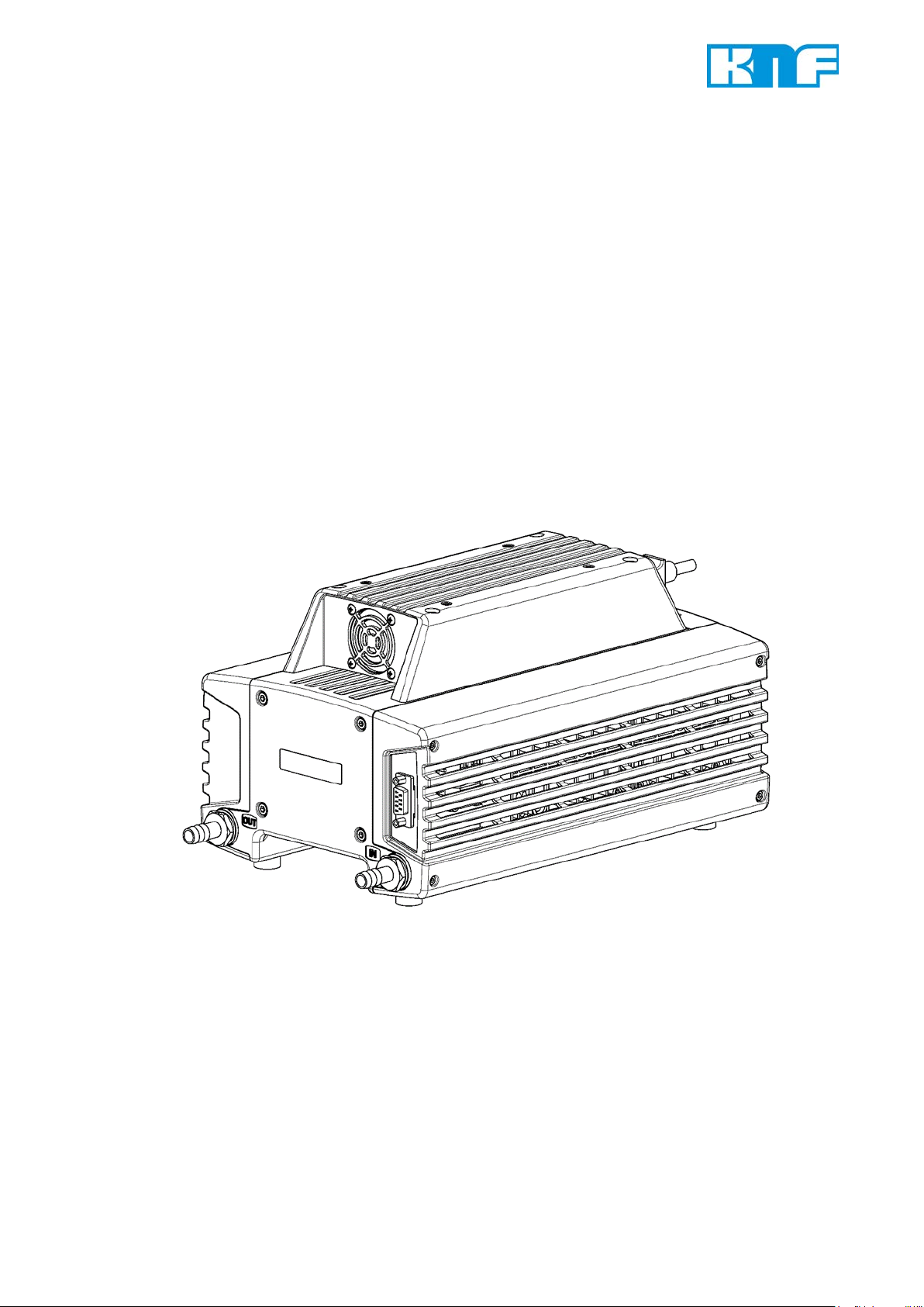
Design and function Diaphragm pump PJ25481-950.50.18
1 Inlet (suction side)
1 Outlet valve
5. Design and function
Design
2 Outlet (pressure side)
3 Power switch, removable
mains cable
4 Sub-D-plug (motor control)
2 Inlet valve
3 Transfer chamber
4 Diaphragm
5 Eccentric
6 Connection rod
7 Pump drive
Fig. 1: Design PJ25481-950.50.18
Function Diaphragm Pump
Fig. 2: Pump head
Diaphragm pumps transfer, compress (depending on pump version) and evacuate gases and vapors.
The elastic diaphragm (4) is moved up and down by the eccentric
(5) and the connection rod (6). In the downward stroke it aspirates
the gas to be transferred via the inlet valve (2). In the upward
stroke, the diaphragm presses the medium out of the pump head
via the outlet valve (1). The transfer chamber (3) is hermetically
separated from the pump drive (7) by the diaphragm.
10 Translation of original Installation Instructi ons , english, KNF 125530-316634 06/18
Page 19

Diaphragm pump PJ25481-950.50.18 Installation and connection
The IP protection class of the pump motor is indicated on the
type plate.
Mounting dimensions
Cooling air supply
Installation location
6. Installation and connection
Only install and operate the pumps under the pneumatic operating
parameters and conditions described in Chapter 4, Technical Data.
Observe the safety precautions (see Chapter 3).
6.1. Installation of the pump
Choose a safe location (flat surface) for the pump.
Before installation, store the pump at the installation location to
bring it up to ambient temperature.
See Fig. 3 for m ounting di mensions.
Fig. 3: Mounting dimensions PJ25481-950.50.18 (All dimensional tolerances conform to DIN ISO 2768-1, Tolerance Class V)
Install the pump so that the motor fan can intake sufficient
cooling air.
Make sure that the installation location is dry and the pump is
protected against rain, splash, hose and drip water as well as
other pollutions.
Make sure, that the installation location is accessible for
maintenance and service.
Install the pump at the highest point in the system to prevent
condensate from collecting in the pump head.
Protect the pump from dust.
Translation of original Installation Instructi ons , english, KNF 125530-316634 06/18 11
Page 20

Installation and connection Diaphragm pump PJ25481-950.50.18
Personal injury and/or damage to property because
of vibration
In conjunction with adjacent components, vibration of
the pump may result in crushing and/or damage to
these components.
Foreign matter protection
Protect the pump against grease and oils.
Protect the pump from vibrations and jolts.
WARNING
Make sure that vibrations of the pump do not re-
sult in hazards associated with adjacent components.
Protect the pump against contact and intrusion of foreign mat-
ter.
12 Translation of original Installation Instructi ons , english, KNF 125530-316634 06/18
Page 21

Diaphragm pump PJ25481-950.50.18 Installation and connection
Extreme danger from electrical shock
Only have the pump connected by an authorized
The voltage must not vary by more than + 10% and – 10%
from that shown on the type plate.
Ensure sufficient dimensioning of the connection cables.
Personal injury or damages to property by ejected
protective
If the
pump hasn’t been removed, it could be ejected because of the overpressure during operation.
Connected
Pump exhaust
6.2. Electrical connection
specialist.
DANGER
When connecting the device to a power source, the relevant
standards, directives, regulations, and technical standards
must be observed.
Connecting pump
1. Compare the supply data with the data on the motor plate. For
maximum operating current of the pump see pump’s type
plate.
Only have the pump connected when the power
supply is disconnected.
components
2. Insert the mains cable plug into a properly installed shockproof
socket.
6.3. Pneumatic connection
plugs
CAUTION
Only connect components to the pump which are designed for
the pneumatic data of the pump (see Chapter 4, Technical
Data).
If the pump s used as a vacuum pump, safely discharge the
pump exhaust at the pump’s pneumatic outlet.
protective plug at the pressure side of the
Remove the protective plug during the installa-
tion.
Translation of original Installation Instructi ons , english, KNF 125530-316634 06/18 13
Page 22

Installation and connection Diaphragm pump PJ25481-950.50.18
A marking on the pump head shows the direction of flow.
Confusion between suction and pressure sides can lead to
breakage of connected components on the suction and pressure sides.
Connecting pump
1. Remove the protective plugs from the hose connection
threads.
2. Connect the suction line and pressure line (see Chapter 4,
Tab. 7 for mounting dimensions).
3. Lay the suction and pressure line at a downward angle to prevent condensate from running into the pump.
14 Translation of original Installation Instructi ons , english, KNF 125530-316634 06/18
Page 23

Diaphragm pump PJ25481-950.50.18 Operation
Operational requirements
Pump
All hoses attached properly.
Danger of burns from hot pump parts or hot medium
During or after operation of the pump, some pump
parts may be hot.
Injury of the eyes
During excessive approach to the inlet or outlet of
the pump, the eyes could be injured by the upcoming
vacuum or overpressure.
7. Operation
7.1. Initial start-up
Fan openings not blocked.
Specifications of the power supply corre-
spond with the data on the pump’s t ype plate.
Ensure that the pump outlet is not closed or
constricted.
Tab. 8
7.2. Start up
WARNING
WARNING
Only operate the pumps under the operating parameters and
conditions described in Chapter 4. Technical Data.
Make sure the pumps are used properly (see Chapter 2.1).
Make sure the pumps are not used improperly (see Chapter
2.2).
Observe the safety precautions (see Chapter 3).
Allow the pump to cool after operation.
Take safety precautions against the contact of
hot parts/media.
Don’t look into the pump’s inlet or outlet during
the operation.
Translation of original Installation Instructi ons , english, KNF 125530-316634 06/18 15
Page 24

Operation Diaphragm pump PJ25481-950.50.18
Hazard of the pump head bursting due to excessive
pressure increase
Only throttle or regulate the air or gas quantity in
Excessive pressure (with all of the related hazards) can be prevented by placing a bypass line with a pressure
tween the pressure and suctions sides of the pump. For further
information, contact our technical adviser (contact data: see
www.k
Automatic starting can cause personal injury and
pump damage
When the operation of the pump is interrupted by the
thermal
sors, the pump will restart automatically after cooling
down.
The pump may not start up against pressure during switch-on.
This also applies in operating following a brief power failure.
a
This activates the
overload switch and the pump switches off.
Depending on the applied electrical voltage, initialization of the
electronics may take up to one second before the pump starts.
Pump standstill
Do not exceed max. permissible operating pres -
WARNING
sure (see Chapter
Monitor pressure during operation.
If the pressure exceeds the maximum permissi-
ble operating pressure, immediately switch off
pump and eliminate fault (see Chapter
bleshooting).
the suction line to prevent the maximum permis-
sible operating pressure from being exceeded.
If the air or gas quantity in the pressure line is
throttled or regulated, make sure that the maxi-
mum permissible operating pressure is not ex-
ceeded.
Ensure that the pump outlet is not closed or con-
stricted.
4. Technical Data.
9. Trou-
With the pump at a standstill, open pressure and suction lines to
normal atmospheric pressure.
WARNING
16 Translation of original Installation Instructi ons , english, KNF 125530-316634 06/18
7.3. Switching Pump on/off
Switching pump on
Make sure that normal atmospheric pressure is present in the
lines during switch-on.
Pumpe am Netzschalter einschalten (siehe Fig. 1/3 in Kapite l
5).
nf.com).
pump starts against pressure, it may block.
-relief valve be-
switch or the trigging device for PTC sen-
Take all necessary care to prevent this leading
to a dangerous situation.
If
Page 25

Diaphragm pump PJ25481-950.50.18 Operation
Elektrische Anschlüsse / Electrical connection
Litzenbelegung / lead assignment
Signalname
5V Ausgangsspannung
Masse
Masse
Ausgangssignal Drehzahl
Versorgung Gasballastventil
Eingangssignal Drehzah lre gel ung
Ausgangssignal Fehler
Eingangssignal Remote EIN/AUS
Masse Gasballastventil
5V Ausgangsspannung U5V / 5V Power supply U5V
Ausgangsspannung DC
Max. Ausgangsstrom
External actuation
Pin Nr. Funktion / function
1
2
3
4
5
6
7
8
9
5V power supply
Ground
Ground
Output signal speed
Supply gas ballast valve
Input signal speed control
Output signal fault
Input signal Remote ON/OFF
Ground gas ballast valve
Output voltage range DC
signal name
U5V
GND
GND
U
Spd
U
+GB
U
Ctrl
U
Flt
U
Rmt
U
-GB
[V] 5 ± 0.2
Max. current output
Translation of original Installation Instructi ons , english, KNF 125530-316634 06/18 17
[mA] 170
Tab. 9 (part 1): Connection plan motor electronics
Page 26

Operation Diaphragm pump PJ25481-950.50.18
Ausgangssignal Drehzahl U
/ Output signal speed U
Pulse pro Umdrehung
Pulstastverhältnis
PWM-Signal
PWM Frequenz
Ausgangspegel „high“
5
Ausgangspegel „low“
0
Max. Strombelastbarkeit
Ausgangsimpedanz @ 1 kHz
Eingangssignal Drehzahlregelung U
/ Input signal speed control U
Steuerspannungsbereich DC
Steuerspannungsbeschreibung:
min.
max.
Max. Eingangsspannung
Schwellenspannung
PWM Frequenzbereich
100
Eingangspegel „high”
5
Eingangspegel „low”
0
Tastgradbereich
Tastgradbeschreibung:
min.
max.
Eingangsimpedanz @ 1kHz
Analog
Pulses per revolution
Pulse duty cycle
PWM frequency
Output level „high“
Output level „low“
Max. current carrying capacity
Output impedance @ 1 kHz
Control voltage range DC
min. Pumpe min. Förderleistung
max. Pumpe max. Förderleistung
Analog
Contol voltage description
min. pump min. flow
max. pump max. flow
Spd
Ctrl
Spd
[-] 1
[%] 50 ± 1
[Hz] 50 ± 0.5
[V]
[V]
[4.1 … V5V]
[0 … 0.6]
[mA] 10
[kΩ] ≥ 9
Ctrl
[V] 0 … 5
[V]
0.1 5
Max. input voltage
Treshold voltage
PWM frequence range
Input level „high”
Input level „low”
PWM-Signal
Duty cycle range
min. Pumpe min. Förderleistung
max. Pumpe max. Förderleistung
Duty cycle description
min. pump min. flow
max. pump max. flow
Input impedance @ 1kHz
[V] 5.5
[mV] 25 ± 0.5
[Hz]
[V]
[V]
[%] 0 … 100
[%]
[kΩ] ≥ 12
Tab. 9 (part 2): Connection plan motor electronics
[50 … 150]
[4.2 … 5.5]
[0 … 0.9]
2 100
18 Translation of original Installation Instructi ons , english, KNF 125530-316634 06/18
Page 27

Diaphragm pump PJ25481-950.50.18 Operation
Ausgangssignal Fehler U
/ Output signal fault U
Eingangspegel „high“ Fehler vorhanden
5
Eingangspegel „low“ kein Fehler
0
Max. Strombelastbarkeit
Ausgangsimpedanz @ 1kHz
Eingangssignal Remote EIN/AUS U
/ Input signal Remote ON/OFF U
Eingangspegel „high“ Motor EIN
5
Eingangspegel „low” Motor AUS
0
Eingangsimpedanz @ 1 kHz
Versorgung Gasballastventil U
/ Supply gas ballast valve U
Steuerspannung DC
Max. Stromaufnahme
To start the motor, Pin 5 must be bridged to the ground of the
controller connection.
Adjusting the flow rate
Remote ON/OFF
Vapors as media
Flt
Input level „high“ err or d etec ted
Input level „low“ no er ror
Max. current carrying capacity
Output impedance @ 1kHz
Input level „high“ motor ON
Input level „low” motor OFF
Input impedance @ 1 kHz
+GB
Control voltage DC
Max. current consumption
Tab. 9 (part 3): Connection plan motor electronics
The flow rate can be varied by an external actuation (Sub-D-plug,
see Tab. 9).
Rmt
Flt
[V]
[V]
[3.9 … 5.5]
[0 … 0.9]
[mA] 10
[kΩ] ≥ 9
Rmt
[V]
[V]
[3.9 … 5.5]
[0 … 0.9]
[kΩ] ≥ 1.8
+GB
[V] 24 ± 10%
[mA] ≤ 50
The speed of the pump is controlled by a control voltage.
Please contact our KNF customer service for further information.
Remote ON/OFF is through an 9-pin controller connection (Pin 8,
see Tab. 9).
Please contact our KNF customer service for further information.
Switching off the pump
The life of the diaphragm is prolonged the formation of condensate
is avoided. Therefore the following precautions should be taken:
Run the pump for a few minutes to warm it up before handling
saturated or nearly saturated vapors.
KNF recommends: When transferring aggressive media, flush
the pump prior to switch off (see Chapter 8.2.1) to increase the
service life of the diaphragm.
Switch off pump with power switch (Fig. 1 at Chapter 5).
Restore the system to normal atmospheric pressure (release
pneumatic pressure in pump).
Pull out the pump’s main plug.
Translation of original Installation Instructi ons , english, KNF 125530-316634 06/18 19
Page 28

Servicing Diaphragm pump PJ25481-950.50.18
Component
Servicing interval
Pump - Regular inspection for external
damage or leaks
Hose connections
Regular inspection for external
damage or leaks
Diaphragm and valve
Replace when pumping capacity
Silencer
Change if it is dirty
When cleaning, make sure that no liquids enter the inside of
the housing.
Dangerous substances in the pump can cause a
health hazard.
Depending on the substance transferred, caustic
burns or poisoning are possible.
Danger of burns from hot pump parts
The pump head or motor may be hot even after the
pump has been shut off.
Requirements
8. Servicing
8.1. Servicing schedule
-
-
plates
Tab. 10
8.2. Cleaning
decreases, or sooner
-
8.2.1. Flushing pump
Before switching off the pump, flush it with air (or with inert gas
if required for safety reasons) under atmospheric conditions
(ambient pressure) for about five minutes.
8.2.2. Cleaning pump
Pump disconnected from mains and de-energized.
WARNING
Wear protective clothing if necessary, e.g. pro-
tective gloves.
Take the proper steps to clean the pump.
CAUTION
Solvent should be used for cleaning only if the head materials
are not corroded (ensure compatibility of the material).
If compressed air is available, blow out the parts.
20 Translation of original Installation Instructi ons , english, KNF 125530-316634 06/18
Allow the pump to cool off after operation.
Page 29

Diaphragm pump PJ25481-950.50.18 Servicing
Spare part/tool
Spare parts set according to spare parts list, Chapter 10
Allen key 2-mm (hexagon)
Phillips screwdriver No. 2
Allen key 4-mm (hexagon)
Felt-tip pen
Dangerous substances in the pump can cause a
health hazard.
Depending on the substance transferred, caustic
burns or poisoning are possible.
Danger of burns from hot pump parts
The pump head or motor may be
pump has been shut off.
Requirements
Spare parts/tools
Information on procedure
8.3. Replacing diaphragm and reed valves
Pump disconnected from mains and de-energized
Pump is clean and free of hazardous materials.
Hoses removed from pump’s pneumatic inlet and outlet.
Tab. 11
Always replace diaphragm and valve plates together to main-
tain the pump performance.
WARNING
Wear protective clothing if necessary, e.g. pro-
tective gloves.
Flush the pump before replacing the diaphragm
and valve plates (see Chapter
CAUTION
Allow the pump to cool off after operation.
8.2.1).
hot even after the
Translation of original Installation Instructi ons , english, KNF 125530-316634 06/18 21
Page 30

Servicing Diaphragm pump PJ25481-950.50.18
1 8x attachment screws
2
3
4
5
6
7
8
9
10
11 2x connection blocks .50
12
13
14
15
16
17
18
19
20
Fig. 4: Exploded drawing PJ25481-950.50.18
(head cover)
4x head screws
16x attachment screws
(head)
4x head plates
8x O-rings (ø24 x 2)
4x intermediate plates
4x diaphragms
1x connection cover
4x attachment screws
(connection cover)
2x O-rings (ø7,65 x1,78)
2x flat seals
2x connection block s .1.2
2x attachment screws
(connection .1.2)
8x valve plates
6x valve plates
6x O-rings (ø18,77 x
1,78)
6x O-rings (ø10 x 2,5)
2x head covers
2x attachment screws
(connection .50)
Removing the pump head
1. Undo the eight screws (Fig. 4/1) and remove the head covers
(20).
2. Undo the connection cover’s (8) attachment screws (Fig. 5/9)
and remove the connection cover.
22 Translation of original Installation Instructi ons , english, KNF 125530-316634 06/18
3. Remove the head connection’s (11) and (14) screws (10) and
(15) and remove the head connections.
Page 31

Diaphragm pump PJ25481-950.50.18 Servicing
Fig. 5: Disassembling the head connections
4. Remove O-rings (Fig. 6/12) and flat seals (13).
Fig. 6: Marking the pump
5. Head 1 (Fig. 6/I):
Use a felt-tip pen to apply a single mark (M) to the head plate,
intermediate plate, and compressor housing.
6. Head 2 (Fig. 6/II):
Use a felt-tip pen to apply two marks (M) to the head plate, intermediate plate, and compressor housing.
7. Head 3 (Fig. 6/III):
Use a felt-tip pen to apply three marks (M) to the head plate,
intermediate plate, and compressor housing.
Translation of original Installation Instructi ons , english, KNF 125530-316634 06/18 23
Page 32

Servicing Diaphragm pump PJ25481-950.50.18
During re-assembly, refer to the marks on the individual heads
to ensure th
8. Head 4 (Fig. 6/IIII):
Use a felt-tip pen to apply four marks (M) to the head plate, intermediate plate, and compressor housing.
at the parts are properly re-assembled.
9. Undo the 16 attachment screws (Fig. 4/3) on the heads (1 to 4)
and remove the heads (1 and 2 as well as 3 and 4).
10. Pull apart heads 1 (Fig. 7/I) and 2 (II) and heads 3 (III) and 4
(IIII) and remove O-rings (19).
Fig. 7: Removing the o-rings
11. On all four heads, undo the head screw (Fig. 8/2) in the head
plate (4) and remove head plate from the intermediate plate
(6).
24 Translation of original Installation Instructi ons , english, KNF 125530-316634 06/18
Page 33

Diaphragm pump PJ25481-950.50.18 Servicing
Use caution to prevent the diaphragm spacers (21) located between the diaphragm and the connecting rod from falling into
the pump housing. The diaphragm and the connecting rod from
falling into the housing. The diaphragm spacers (
installed in the same quantity as before in order to ensure th
pump’s pneumatic performance.
Fig. 8: Exploded drawing of pump heads 1 and 2
Replacing the diaphragms and valve plates
1. Manually remove the four diaphragms (Fig. 9/7) by turning
them in the counterclockwise direction.
21) must be
e
Fig. 9: Replacing diaphragm
Translation of original Installation Instructi ons , english, KNF 125530-316634 06/18 25
Page 34

Servicing Diaphragm pump PJ25481-950.50.18
Before you finally tighten the diaphragms, you are recommended to move the diaphragm to the upper dead center.
The upper and lower sides of the valve plates are identical.
When inserting the O-rings, make sure that they are the correct
size and color (head 4: black O
Refer to for arrangement and alignment of disk springs and the
screw’s washer.
When inserting the O-rings, make sure that they are the correct
size and color (head 4: black O
2. Remove from the intermediate plates (Fig. 8/6) the valve plates
(16) and (17) and the O-rings (5) and (18).
3. Manually screw the ne diaphragms (Fig. 9/7) into the connecting rod’s threads and tighten to hand tightness.
4. Insert the new valve plates (Fig. 8/16) and (17) and the new O-
rings (5) and (18) into the intermediate plates (6).
Install intermediate plates and head cover
1. Place head plate (Fig. 8/4) onto the int ermediate plates (6), observing the felt-tip pen marks (Fig. 6/M).
2. With your hands, caref ull y and lightl y tighte n the head plat e’s
head screw (Fig. 8/2) on all four heads (tightening torque:
60 Ncm).
3. Place three O-rings (Fig. 7/19) into each of the head connection holes.
-rings).
-rings).
Fig. 10: Aligning the
disk spring
4. Press together heads 1 and 2 (Fig. 6/I and II) and heads 3 and
4 (III and IIII).
5. Place heads 1 and 2 and heads 3 and 4 onto the compressor
housing; alternately tighten attachment screws (Fig. 4/3) to
hand-tightness (tightening torque: 3.5 Nm).
6. Insert O-rings (Fig. 6/12) and flat seals (13) into the head connection receiver.
7. Reinstall the head connections:
To do this, manually tighten the head connections’ attachment
screws (Fig. 5/10 and 15).
8. Reinstall the head connection cover (8):
To do this, manually tighten the head connection cover’s attachment screws (9).
9. Reinstall the head covers (Fig. 4/20):
To do this, manually tighten the eight attachment screws (1).
10. Properly dispose of the old diaphragms, valve plates, and Orings.
26 Translation of original Installation Instructi ons , english, KNF 125530-316634 06/18
Page 35

Diaphragm pump PJ25481-950.50.18 Servicing
Final steps
1. Reconnect suction and pressure line on the pump.
2. Reconnect the pump to the mains.
If you have any questions about servicing, call your KNF technical
adviser (contact data: see www.knf.com).
Translation of original Installation Instructi ons , english, KNF 125530-316634 06/18 27
Page 36

Troubleshooting Diaphragm pump PJ25481-950.50.18
Extreme danger from electrical shock!
Pump does not transfer
Cause
Fault remedy
Pump not connected to the
Connect pump to the mains.
No voltage in the mains.
Check room fuse and switch on if necessary.
The motor board’s overcur-
Separate pump from the mains.
The pump must be separated from the mains for several
seconds before the electronics will permit restarting.
Connections or hoses are
Check hoses and connections.
External valve is closed or filter
Check external valves and filters.
Condensate has collected in the
Detach the condensate source from the pump.
Diaphragm or valve plates are
Replace diaphragm and valve plates (see Chapter 8.3).
Flow rate, pressure or vacuum too low
Cause
Fault remedy
Condensate has collected in the
Detach the condensate source from the pump.
Presence of positive pressure
Change the pressure conditions.
Cross-section of pneumatic
Disconnect the pump from system and determine output
If applicable, use larger-diameter hoses or connectors.
Leaks in connections, hoses or
Make sure the hoses and connections.
Pump head components are
Clean head components.
9. Troubleshooting
Disconnect the pump power supply before work-
ing on the pump.
DANGER
Check the pump (see Tab. 12 and Tab. 13).
mains.
Make sure the pump is de-energized and se-
cure.
rent protection circuit has
activated.
Maximum temperature of
motor board is exceeded.
Determine and remove the cause of the overcurrent (for ex-
ample: improper pressure, liquid in the pump heads).
Maximum blocking time of
the rotor is exceeded.
blocked.
Remove blockage.
is clogged.
pump head.
Flush the pump (see Chapter 8.2.1).
worn.
Tab. 12
The pump does not achieve the output specified in the Technical data or the data sheet.
pump head.
Flush the pump (see Chapter 8.2.1).
on the pressure side with simultaneous vacuum or positive
pressure on the suction side.
hoses or connectors too narrow
or restricted.
pump head.
values.
Remove restriction (e.g. valve) if necessary.
Remove any parts or particles causing blockages.
soiled.
28 Translation of original Installation Instructi ons , english, KNF 125530-316634 06/18
Page 37

Diaphragm pump PJ25481-950.50.18 Troubleshooting
Pump head components are
Clean head components.
Diaphragm or valves plates are
Replace diaphragm and valve plates (see Chapter 8.3).
Diaphragm and valve plates
Make sure that the shim rings have been replaced onto the
Check head connection and hose connections for leaks.
soiled.
worn.
have been replaced.
diaphragm screw thread.
Tab. 13
Fault visualization on motor contr oller
The excess of the overcurrent limit, the excess of the maximum
temperature of the motor board or the blocking of the rotor is
shown as a fault. A red LED on the BLDC motor controller signals
the cause of the fault.
Optional settings:
If desired, the motor controller can be programmed so that the error output voltage exhibits the same characteristics as the LED.
With factory settings, only 1 or 0 are logically outputted as voltage
at the fault output.
Fig. 11: LED blinking duration according to different faults
To delete the error condition the motor has to be disconnected
from the mains.
Fault cannot be rectified
If you are unable to identify the cause of the problem, please send
the pump to KNF customer services (contact data: see
www.knf.com).
1. Flush the pump (see Chapter 8.2.1).
2. Clean the pump (see Chapter 8.2.2).
3. Send the pump, together with completed Health and Safety
Clearance and Decontamination Form (Chapter 12), to KNF
stating the nature of the transferred medium.
Translation of original Installation Instructi ons , english, KNF 125530-316634 06/18 29
Page 38

Returns Diaphragm pump PJ25481-950.50.18
10. Returns
Pumps and systems used in laboratories and process-based
industries are exposed to a wide variety of conditions. This means
that the components contacting pumped media could become
contaminated by toxic, radioactive, or otherwise hazardous substances.
For this reason, customers who send any pumps or systems back
to KNF must submit a Health and safety clearance and decontamination form in order to avoid a hazardous situation for KNF employees. This Health and safety clearance and decontamination
form provides the following information, among other things:
physiological safety
whether medium-contacting parts have been cleaned
whether the equipment has been decontaminated
media that have been pumped or used
To ensure worker safety, work may not be started on pumps or
systems without a signed Health and safety clearance and decontamination form.
For optimal processing of a return, a copy of this declaration
should be sent in advance via e-mail, regular mail, or fax to KNF
Customer Service (co ntac t data: see www.knf.com). In order to
avoid endangering employees who open the shipment’s packaging, despite any residual hazards, the original version of the Health
and safety clearance and decontamination form must accompany
the delivery receipt on the outside of the packaging.
The template for Health and safety clearance and decontamination
form is included with these Operating Instructions and may also be
downloaded from the KNF website.
The customer must specify the device type(s) and serial number(s)
in the Health and safety clearance and decontamination form in order to provide for the unambiguous assignment of the Declaration
to the device that is sent to KNF.
In addition to the customer’s declaration of physiological safety, information about operating conditions and der customer’s application are also of importance to ensure that the return shipment is
handled appropriately. Therefore, the Health and safety clearance
and decontamination form requests this information as well.
.
30 Translation of original Installation Instructi ons , english, KNF 125530-316634 06/18
Page 39

Diaphragm pump PJ25481-950.50.18 Health and safety clearance and decontamination form
11. Health and safety clearance and decon-
tamination form
Translation of original Installation Instructi ons , english, KNF 125530-316634 06/18 31
Page 40

KNF worldwide
Find your
local KNF partner on www.knf.com
Page 41

Experts in Thermostatics
Pump module – PM
D39489
Last updated 09/2018
English
Memmert GmbH+ Co.KG
Willi-Memmert-Straße 90-96 I 91186 Büchenbach
Phone +49 9122 925-0 | Fax +49 9122 14585
E-mail: sales@memmert.com
facebook.com/memmert.family
The expert platform: www.atmosafe.net
 Loading...