

Members Mark Y0202xc Owner's Manual

Owner's Manual
!
Liquid Propane Gas Grill
MODEL Y0202XC LP
Natural Gas Grill
MODEL Y0202XC NG
MODEL Y0202XC LP SHOWN
Grill Information Center: If you have questions about assembly or grill operation, or if there are damaged or
missing parts when you unpack this unit from the shipping boxes, call us 8am - 4:30 pm CST,
Monday through Friday at: 1-800-770-9769
WARNING:
Read this Owner's Manual carefully and be sure your
gas grill is properly assembled, installed and
maintained. Follow all leak check procedures carefully in this manual prior to grill operation. Do this
even if the grill was store assembled. Failure to
follow these instructions could result in serious bodily
injury and/or property damage. This grill is intended for
outdoor use only and is not intended to be installed in
or on recreational vehicles or boats.
Note to Installer: Leave this Owner's Manual
with the consumer after delivery and/or installation.
Note to Consumer: Leave this Owner's Manual in
a convenient place for future reference.
Important Note: This grill is manufactured to
exact specifications. Model Y0202XC LP is certified
for use with LP gas and Model Y0202CX NG is
certified for use with Natural Gas. You can not
convert this grill from one fuel type to the other.
For your safety, conversion kits are not available.
Any attempt to convert your grill will void your
warranty.
Manufacturer:
Grand Hall Enterprise Co., Ltd.
9th Fl., No.298, Rueiguang Rd., Neihu,
Taipei, Taiwan (114)
P80146046A - Date: 08/12/2003
Table of Contents
Read These Safety Instructions
Warranty.....................................................2
Safety Instructions.....................................2
Natural Gas Safety Instructions...............4
Pre-Assembly Instructions..............................5
Hardware, Parts Diagram and Lists.....6
Rotisserie, Parts Diagram and Lists...10
Assembly Instructions...............................11
Lighting Instructions..................................18
Rotisserie Instructions.............................20
Back Burner, Rotisserie Instructions.......22
Cleaning and Maintenance Instructions....23
Frequently Asked Questions..................25
Cooking Instructions................................26
Cooking Guide and Recipes................27
Member's Mark Grill Warranty
Full 1-Year Warranty on Grill
For one year from the date of purchase, the Manufacturer
will repair or replace, at their option, any grill part (except
for paint loss, rusting, AA batteries) that is defective
in material or workmanship.
Limited Warranty on Selected Grill Parts
From the date of purchase for the designated time
periods stated below, the Manufacturer will replace the
following grill parts if they are defective in material or
workmanship. You will be charged shipping and handling.
• Lifetime of the grill: Stainless steel parts
(except for discoloration due to normal use or
excessive heat, and scratches or dents caused
by normal use and improper maintenance).
Aluminum Castings (except for paint loss)
• 2 Years: Cast-iron Burners
• For Warranty Service: Call our Grill Information
Center 8am - 4:30pm CST, Monday through
Friday at 1-800-770-9769
Warranty Restrictions:
• This warranty does not cover surface rust or
natural oxidation.
• This warranty is void if grill is used for
commercial or rental purposes.
• This warranty applies only when the grill is used
in the United States.
• This warranty gives you specific legal rights, and
you may also have other rights which vary from
state to state. See back cover for warranty details.
FOR YOUR SAFETY
If you smell gas:
1. Shut off gas to the appliance.
2. Extinguish any open flame.
3. Open lid.
4. If odor continues, immediately call your
gas supplier or your fire department.
FOR YOUR SAFETY
Do not store or use gasoline or other flam-
1.
mable vapors and liquids in the vicinity of this
or any other appliance.
An LP gas tank not connected for use shall
2.
not be stored in the vicinity of this or any other
appliance.
!
WARNING
Combustion byproducts produced when
using this product contain chemicals known
to the State of California to cause cancer,
birth defects, or other reproductive harm.
!
WARNING
Failure to comply with these instructions
could result in a fire or explosion that
could cause serious bodily injury, death, or
property damage.
!
WARNING
Your grill will get very hot. Never lean over
the cooking area while using your grill. Do not
touch cooking surfaces, grill housing, grill lid or
any other grill parts while the grill is in
operation, or until the grill has cooled after use.
Failure to comply with these instructions
may result in serious bodily injury.
Grill Installation Codes
This gas grill must be installed in accordance with
all local codes. In areas without local codes, follow
the latest edition of the National Fuel Gas Code
ANSI Z223.1. In Canada, installation must conform
to standard CAN/CGA 1b149.1 or 1-b149.2 (Installation Code for Gas Burning Appliances and
Equipment) and all local codes.
Correct LP Gas Tank Use
LP gas grill models are designed for use with a
standard 20 lb. Liquid Propane Gas (LP gas) tank,
not included with grill box. Never connect your
gas grill to an LP gas tank that exceeds this
capacity. A tank of approximately 12 inches in
diameter by 18-1/2 inches high is the maximum
size LP gas tank to use. You must use an
"OPD" gas tank which offers an Overfill Prevention Device. This safety feature prevents the
tank from being overfilled which can cause malfunction of the LP gas tank, Regulator and/or grill.
The LP gas tank must be constructed and marked
in accordance with specifications of the U.S. Dept.
of Transportation (DOT). In Canada, the LP gas
tank must meet the Canadian Transportation and
Communications (CTC) specifications. Also be sure
to read and follow all LP gas instructions on the
following page.
2

1.
The LP gas tank has a Shut Off Valve,
terminating in an LP gas supply tank valve
outlet, that is compatible with a Type 1 tank
connection device. The LP gas tank must
also have a safety relief device that has a
direct communication with the vapor space of
the tank.
The tank supply system must be arranged
2.
for vapor withdrawal.
The LP gas tank used must have a collar
3.
to protect the tank valve.
Proper Placement and Clearance of Grill
Never use your gas grill in a garage, porch, shed,
breezeway or any other enclosed area. Your gas grill is
to be used outdoors only, at least 24 inches from the
back and side of any combustible surface. Your
gas grill should not be placed under any surface
that will burn. Do not obstruct the flow of ventilation
and combustion air around the gas grill housing.
This outdoor gas grill is not intended to be installed in
or on recreational vehicles and/or boats.
!
WARNING
Failure to comply with these instructions
could result in a fire or explosion that
could cause serious bodily injury, death,
or property damage.
• Never connect an unregulated LP gas tank to
your gas grill. The gas Regulator assembly
supplied with your gas grill is adjusted to have
an outlet pressure of 11" water column (W.C.)
for connection to an LP gas tank.
• Only use the Regulator and Hose Assembly
supplied with your gas grill. Replacement
Regulators and Hose Assemblies must be
those specified by manufacturer.
• Have your LP gas tank filled by a reputable
propane gas dealer and visually inspected and
re-qualified at each filling.
• Never fill the gas tank beyond 80% full.
Have your propane gas dealer check the
release valve after every filling to ensure that it
remains free of defects.
• Always keep LP gas tanks in upright position.
• Do not store (or use) gasoline or other flammable
vapors and liquids in the vicinity of this gas grill.
• An LP gas tank that is not connected for use must
NOT be stored on bottom shelf inside cabinet or in
the vicinity of this or any other gas grill.
• Do not subject the LP gas tank to excessive heat.
• Never store an LP gas tank indoors. If you
store your gas grill in the garage or other
indoor location, always disconnect the LP gas
tank first, store it safely outside.
• LP gas tanks must be stored outdoors in a
well-ventilated area and out of the reach of
children. Disconnected LP gas tanks
must not be stored in a building, garage or
any other enclosed area.
• When your gas grill is not in use the gas
must be turned off at the LP gas tank.
• The Regulator and Hose assembly must be
inspected before each use of the grill. If there
is excessive abrasion or wear or if the hose
is cut, it must be replaced prior to the grill
being used again.
• Keep the gas Regulator Hose away from hot
grill surfaces and dripping grease. Avoid
unnecessary twisting of hose. Visually inspect
hose prior to each use for cuts, cracks,
excessive wear or other damage. If the Hose
appears damaged do not use the gas grill,
call our Grill Information Center for a
replacement, at 1-800-770-9769.
• Never light your gas grill with the Lid closed
or before checking to insure the Burner Tubes
are fully seated over the Gas Valve Orifices.
• Never allow children to operate your grill. Do
not allow children to play near your grill.
!
WARNING
A strong gas smell, or the hissing sound of
gas indicates a serious problem with your
gas grill or the LP gas tank. Failure to
immediately follow the steps listed below
could result in a fire or explosion that could
cause serious bodily injury, death, or property damage.
• Shut off gas supply to the gas grill.
• Turn the Control Knobs to OFF position.
• Put out any flame with a Class B fire
extinguisher.
• Open Grill Lid.
• Get away from the LP gas tank.
• Do not try to fix the problem yourself.
• If odor continues or you have a fire you cannot
extinguish, call your fire department. Do not call
near the LP gas tank because your telephone is
an electrical device and could create a spark
resulting in fire and/or explosion.
NOTE: The normal flow of gas through the
Regulator and Hose Assembly can create a
humming sound. A low volume of sound is
perfectly normal and will not interfere with
operation of the grill. If humming sound is
loud and excessive you may need to purge
air from the gas line or reset the Regulator
excess gas flow device. This purging procedure should be done every time a new LP
gas tank is connected to your grill. For help
call the Grill Information Center.
Grill Information Center, 8:00am-4:30pm
CST, Monday through Friday at:
1-800-770-9769
3
Natural Gas Safety Instructions
• Your Natural Gas Grill is designed to operate on
Natural Gas only, at a pressure of 7" water column
(W.C.) (1/4 psig or 1.75 kpa), regulated at the
residential meter. Check with your gas utility
company for local gas pressure and with your local
municipality for building code requirements. If
your residential gas line pressure has not been
regulated to 7" W.C., contact your local gas
utility company for professional assistance.
• The gas pressure Regulator supplied with this
appliance must be used. This Regulator is set
for an outlet pressure of 4" W.C.
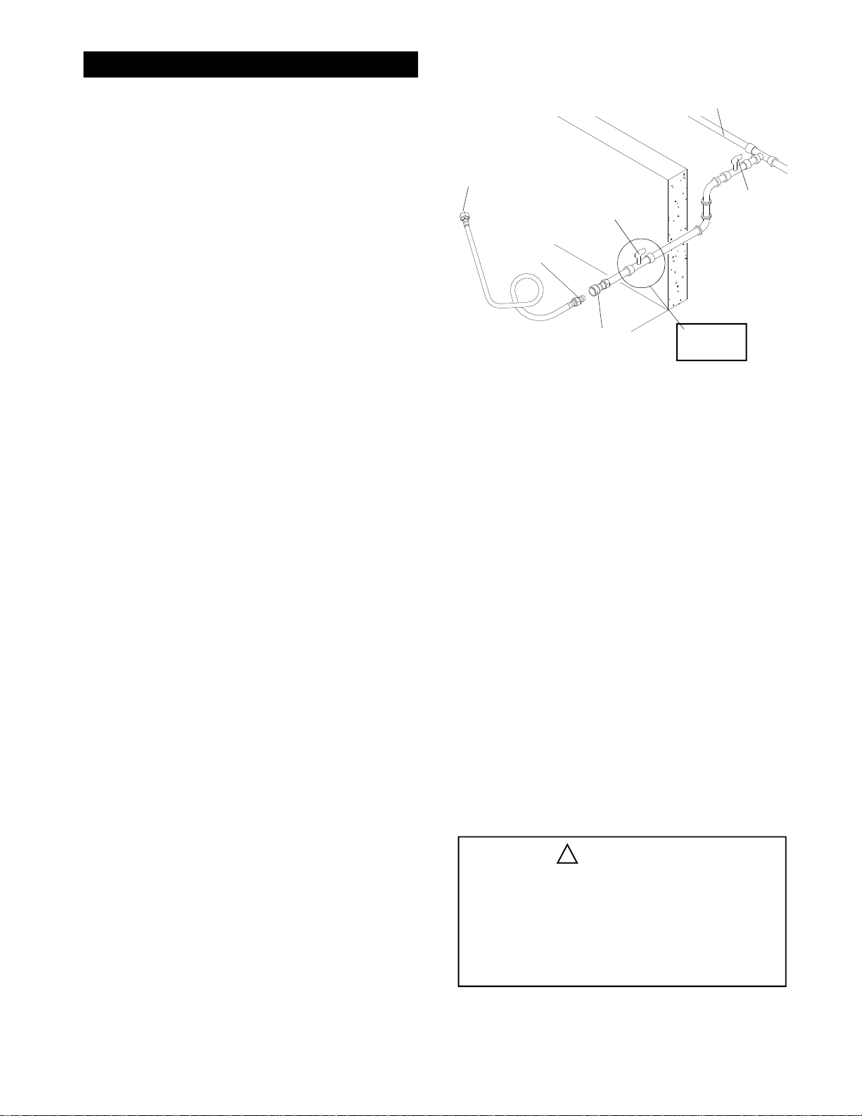
• It is recommended that a Shut Off Valve be installed
at the gas supply source outdoors. Install at a point
after the gas pipe exits the outside wall and before the
Quick Disconnect Hose, or install it at the point
before the gas line piping enters the ground. See
Figure 1.
• Pipe sealing compound or pipe thread tape resistant
to the action of Natural Gas must be used on all male
pipe threads when making the connection.
Figure 1
(For Natural Gas Model Only)
NATURAL GAS SUPPLY
I
N
S
I
D
E
W
A
L
L
A
L
L
LOCKING
GAS
SHUT OFF
VALVE
Additional
Hardware Not
Included
TO NATURAL GAS
REGULATOR
MALE
FITTING
O
U
T
S
I
D
E
W
LOCKING GAS
SHUT OFF VALVE
QUICK
DISCONNECT
Gas Line Piping
If the length of line required does not exceed 50 feet,
use a 5/8" O.D. tube. One size larger should be used
for lengths greater than 50 feet.
• Disconnect your gas grill from fuel source when
the gas supply is being tested at high pressures.
This gas grill and its individual Shut Off Valve must
be disconnected from the gas supply pipe system
during any pressure testing of that system at
pressure in excess of 1/2 psi (3.5kpa).
• Turn off your gas grill when the gas supply is
tested at low pressures. The grill must be isolated
from the gas supply pipe system by closing its
individual Manual Shut Off Valve during any
pressure testing of the gas supply pipe system at
pressures equal to or less than 1/2 psi (3.5kpa).
• The Quick Disconnect connects to a 3/8 inch NPT
thread from gas source. The Quick Disconnect
fitting is a hand operated device that automatically
shuts off the the flow of gas from the source when
it is disconnected.
• The Quick Disconnect fitting can be installed
horizontally, or pointing downward. DO NOT install
the fitting with the opening pointing upward
because the fitting could collect water and debris.
• The Dust Covers (plastic plugs) provided with the
Quick Disconnect help keep the open ends
clean while disconnected.
• The outdoor connector must be firmly attached to
a ridged permanent construction.
• The Quick Disconnect MUST BE installed above
ground.
Gas piping may be copper tubing, type K or L;
polyethylene plastic tube, with a minimum wall
thickness of .062 inch; or standard weight (schedule
40) steel or wrought iron pipe.
Copper tubing must be tin-lined if the gas contains
more than 0.3 grams of hydrogen sulfide per 100
cubic feet of gas.
Plastic tubing is suitable only for outdoor, underground use.
Gas piping in contact with earth, or any other material which may corrode the piping, must be protected
against corrosion in an approved manner.
Underground piping must have a minimum of 18"
cover.
Test Connections
All connections and joints must be thoroughly tested
for leaks in accordance with local codes and all listed
procedures in the latest edition of ANSI Z223.1
!
DANGER
Do not use an open flame to check for
gas leaks. Be sure there are no sparks
or open flames in the area while you
check for gas leaks. This will result in a
fire or explosion which can cause serious
bodily injury or death, and damage to
property.
• WARNING: Do not route the 12 foot Quick
Disconnect Hose under a deck. The hose must be
visible and inspected prior to each grill use.
4

CAUTION: BEWARE OF FLASH-BACK
Pre-Assembly Instructions
CAUTION: Spiders and small insects occa-
sionally spin webs or make nests in the grill
burner tubes during transit and warehousing.
These webs can lead to a gas flow obstruction which could result in a fire in and around
the Burner Tubes. This type of fire is known
as a "FLASH-BACK" and can cause serious
damage to your grill and create an unsafe
operating condition for the user.
Although an obstructed Burner Tube is not the
only cause of "FLASH-BACK", it is the most
common cause.
To reduce the chance of "FLASH-BACK", you
must clean the Burner Tubes before assembling your grill, and at least once a month in
late summer or early fall when spiders are
most active. Also perform this Burner Tube
cleaning procedure if your grill has not been
used for an extended period of time.
To reduce the chance of "FLASH-BACK" (see
CAUTION at left) clean the Burner Tubes and
Burners before fully assembling your grill. Remove the Cotter Pin from the rear underside of
each Burner using a pair of long nose pliers.
Carefully lift each Burner up and away from the
Gas Valve Orifice, then refer to Figure 1 and
perform one of these three cleaning methods:
Bend a stiff wire, (a lightweight coat hanger
1.
works well) into a small hook as shown
below. Run the hook through the Burner
Tube and inside the Burner several times to
remove any debris.
Use a Burner Cleaning Brush, or a bottle
2.
brush with a flexible handle. Run the brush
through the Burner Tube and inside the
Burner several times, removing any debris.
Use an air hose to force air through each
3.
Burner Tube. The forced air should pass
debris or obstructions through the Burner
and out the ports.
Tools Required for Assembly
Phillips Head screw driver
•
Adjustable wrench
•
Long nose pliers - used to remove the
•
Cotter Pin when cleaning the Burners
Open-end wrench (included with Hardware
•
Pack) used to tighten the Casters.
Protective work gloves
•
Eye protection
•
Figure 1
TO CLEAN BURNER TUBE,
INSERT HOOK HERE
GAS COLLECTOR BOX
SPARK ELECTRODE
!
WARNING
The location of the Burner Tube with respect
to the Orifice is vital for safe operation. Check
to ensure the Orifice is inside of the Burner Tube
before using your gas grill. See Figure 2. If the
Burner Tube does not fit over the Valve Orifice,
lighting the Burner may cause explosion
and/or fire.
Figure 2
CONTROL
KNOB
CROSS
SECTION
OF MANIFOLD
BURNER
GAS VALVE
BURNER PORT
SPARK ELECTRODE
GAS COLLECTOR BOX
ORIFICE
ORIFICE
BURNER TUBE
5

Contents for Hardware Pack (Part #P4182A)
Contents for Hardware Pack (Part #P4182A)
Contents for Hardware Pack
The following table illustrates a breakdown of the Hardware Pack. It highlights what components
are used in the various stages of assembly.
Ref.
B.
N.
L.
E.
E.
K.
E.
E.
Q.
K.
E.
U.
K.
U.
Component
1/4" x 2 1/2" Phillips Head Screw
1/4" x 3/4" Phillips Head Screw
1/4" Lock Nut
1/4" x 1/2" Phillips Head Screw
1/4" x 1/2" Phillips Head Screw
3/16" x 1/2" Phillips Head Screw
1/4" x 1/2" Phillips Head Screw
1/4" x 1/2" Phillips Head Screw
M5 x 6mm Phillips Head Screw
(already screwed into Door Handles)
3/16" x 1/2" Phillips Head Screw
1/4" x 1/2" Phillips Head Screw
M4 x 10 Self-Tapping Screw
3/16" x 1/2" Phillips Head Screw
M4 x 10 Self-Tapping Screw
Qty. to use
2
4
4
2
4
4
2
4
4
2
2
1
2
1
Purpose of Component
Attaches Grill Bowl to Cart Leg
Secures Grill Bowl onto the Cart
Attaches LP Fuel Tank Gauge to Side Cart Panel
Attaches Tank Hook and Tank Holder to
LP Fuel Tank Gauge
Secures Rear Panel to Cart
Attaches Door Bracket to the Cart
Attaches Shelf Bracket to Cart Leg
Attaches the Handles onto the Doors
Secures the Rear Wind Shield to the back
of Grill Cart
Secures the Spice Tray to Side Shelf
Secures the Control Panel to Side Burner
and Grill Bowl
U.
M4 x 10 Self-Tapping Screw
E.
1/4" x 1/2" Phillips Head Screw
K.
3/16" x 1/2" Phillips Head Screw
Manual Lighting Stick
R.
Caster Wrench (Part#P05515109E)
V.
"AA" Batteries
S.
(1 For NG Model)
(3 For LP Model)
T.
Door Handles
V.
Caster Wrench
W.
Side Burner Control Knob
X.
Side Burner Control Knob Seat
Y.
Spring
1
4
2
1
1
3
2
1
1
1
1
Attaches Manual Lighting Stick to Side Panel
Secures Side Shelf and Side Burner to
Shelf Brackets
Attaches Natural Gas Regulator to Cart Leg
Attaches to Right Side Panel
Tightens Casters
Powers the Electronic Ignition and LP Fuel
Gauge Display
Attaches to front Doors
Fixing the Casters
Attaches on Side Burner Valve
Attaches on Side Burner Valve
Attaches on Side Burner Valve
6

Contents for Hardware Pack (Part # P06002023A For LP)
Contents for Hardware Pack (Part #P4182A)
Contents for Hardware Pack (Part #P4182A)
(Part # P06002040A For N.G.)
Actual Size and Quantity of Each Hardware Piece:
B. 1/4" x 2 1/2" Phillips Head Screw - QTY 2
E. 1/4" x 1/2"
Phillips Head Screw
QTY. 18 (12 for NG
model)
U. M4 x 10
Self-Tapping Screw
QTY. 3
N. 1/4" x 3/4"
Phillips Head Screw x 4
(found in
door handles)
Q. M5 x 6mm
Phillips Head Screw
QTY. 4
L. 1/4" Lock Nut x 4
K. 3/16" x 1/2"
Phillips Head Screw
QTY. 8 (additional 2 for NG)
R. Manual Lighting Stick (scale 1/2) - QTY. 1 S. "AA" Batteries - QTY. 3
(1 For NG Model)
(3 For LP Model)
T. Door Handle (scale 1/2) - QTY. 2
W. Side Burner Control Knob-QTY. 1
V. Caster Wrench (scale: 1/2)- QTY. 1
Y. Spring-QTY. 1
X. Side Burner Control Knob seat-QTY. 1
Grill Information Center: If you have questions about assembly or grill operation, or if there are damaged
or missing parts when you unpack this unit from the shipping boxes, call us 8am - 4:30 pm CST,
Monday through Friday at: 1-800-770-9769
7

Y0202XC Parts Diagram
Remove all components from both cartons and place within easy reach. Turn the largest carton
upside down and it will provide a comfortable height work surface for grill assembly.
8

10.
11.
12.
13.
14.
16.
17.
18.
19.
20.
21.
22.
23.
24.
25.
26.
29.
30.
31.
32.
33.
33-1.
34.
35.
36.
37.
38.
39.
40.
41.
42.
43.
44.
45.
46.
47.
48.
49.
50.
51.
52.
53.
Lid Plate
1.
Lid Side Panel, Left
2.
Lid Side Panel, Right
3.
Temperature Gauge
4.
Name Plate
5.
Lid Handle
6.
Heat-Insulating Spacer
7.
Cooking Grid
8.
Ceramic Flame Tamer
9.
Rack for Flame Tamer
Burner
Gas Collector Box W. Electrode
Cover for Back Burner
Frame for Back Burner
Back Burner
Spark Electrode
Orifice
Gas Tube Assembly
Grease Draining Tray
Grease Receptacle
Burner Bracket
Bowl Side Panel, Left
Bowl Side Panel, Right
Bowl Front Panel
Bowl Rear Panel
Electric Wire Set
Valve/Manifold Assembly (LP)
Valve/Manifold Assembly (NG)
Control Panel
Control Knob (Side Burner)
Control Knob (Main Burner)
Control Knob (Back Burner)
Spring
Control Knob Seat
Electric Ignitor
AA Battery(3 For LP Model)
(1 For NG Model)
Rear Wind Shield
Rear Panel
Side Shelf
Spice Tray
Side Shelf Bracket
Manual Lighting Stick
Caster
Caster Seat
Door Plate
Door Handle
Door Bracket
Door Stop
Bottom Shelf
Cart Legs,Left(LP)
Cart Legs,Left(NG)
Cart Legs,Right
Regulator(LP)
Y0202XC Parts List
QTY.REF#PART#DESCRIPTION
P00129306A
P00105317T
P00106317T
P0618A
P0435C
P0234A
P5573A
P01602029C
P1736A
P1736B
P1925C
P2623B
P06905001B
P80F1A
P1947A
P2515A
P5643A
P3512A
P2738B
P2717A
P0220321AD
P00705407G
P00706407G
P00740266D
P00741266D
P02615047A
Y0060056
Y0060057
P02909233S
P03424241L
P03424231L
P03424251L
P80E3A
P3432A
P02502154C
P8080A
P06906003C
P07701004A
P01107024B
P05206009A
P01215007D
P5540A
P5115B
P4525B
P04313008A
P0247A
P03301014E
P05510089E
P01005019H
P00901021B
P00901055B
P00902021B
P3632N
1
1
1
1
1
1
2
3
6
1
3
3
1
1
1
1
1
1
1
1
1
1
1
1
1
1
1
1
1
1
3
1
5
5
1
1
1
1
1
4
1
4
4
2
2
1
1
1
1
1
1
1
57a.
57b.
57c.
57d.
57d-1.
57e.
57f.
57g.
57h.
57i.
For the repair or replacement parts you need:
Call our Grill Information Center, 8am - 4:30pm CST,
Monday through Friday at 1-800-770-9769
To make sure you obtain the correct replacement part
(s) for your gas grill please refer to the parts list on
this page. The following information is required to
insure you receive the correct parts:
1. Model and Serial Number (see CSA label on grill)
2. Part Number
3. Description
4. Quantity of parts needed
Please allow sufficient time to process and ship.
IMPORTANT: Keep this Owner's Manual for
convenient referral and for part replacement.
IMPORTANT: Use only factory authorized parts. The
use of any part that is not factory authorized can
be dangerous. This will also void your warranty.
Tank Holder(LP)
54.
Tank Hook(LP)
55.
Tank Gauge(LP)
56.
Side Burner Frame
Side Burner Body
Side Burner Lid
Side Burner Control Panel(LP)
Side Burner Control Panel(NG)
Pot Support
Side Burner
Spark Electrode for Side Burner
Connection Hose(7.3")
Gas Valve for Side Burner(LP)
Gas Valve for Side Burner(NG)
Tank gauge Display(LP)
58.
Regulator (NG)
59.
Hose Kit 12ft.(NG)
60.
Connection Hose (19.8")
61.
Air Shutter (NG)
62.
Owner's Manual
---Hardware Pack (page 7)
---Hardware Pack(NG)
----
QTY.REF#PART#DESCRIPTION
P4042A
P4041A
P80N5A
P01102025B
P02301005B
P1144A
P02904243S
P02904463S
P80E4B
P02002047D
P2632B
P03705024A
P03232064B
P03232065B
P05310031A
Y0080007
P3718A
P03705036A
P80R7A
P80146046A
P06002023A
P06002040A
CSA label located here
1
1
1
1
1
1
1
1
1
1
1
1
1
1
1
1
1
1
3
1
9

Rotisserie Parts Diagram
3
6
3
8
5
3
2
7
4
9
9
9
Rotisserie Parts List Hardware for Rotisserie
QTY.REF#PART#DESCRIPTION
1
1.
Handle
2.
Bushing
3.
3/8"x1/2" Thumbscrew
4.
Collar
5.
Skewer
6.
Holding Fork
7.
Motor Bracket
8.
AC Rotisserie Motor
9.
#10-24x3/4" Screw
Washer
#10-24 Nut
P8083E
P05508092F
P05508094F
P05508091F
P05508093F
P05508090F
P8083K
P07101010A
Y0100052
1
1
3
1
1
2
1
1
2
9. #10-24x3/4" UNC Screw
QTY. 2
3. 3/8"x1/2" Thumbscrew
QTY. 3
10
9. Washer
QTY. 2
9. #10-24 Nut.
QTY. 2

Cart Assembly Instructions
Remove all cart parts, hardware, and Grill Head from
shipping boxes. Raise the Grill Lid and remove all
packed components. Use the parts list to check that
all necessary parts have been included.
Figure 1
LOCKING SCREW
CART LEG BRACKET
NOTCHED HOLE
Assemble the gas grill on a protective work surface
to avoid scratching grill surfaces. Inspect your grill for
damage as you proceed. Do not assemble or operate
your grill if it appears damaged. If there are damaged
or missing parts when you unpack the shipping boxes,
or you have questions during the assembly process,
call our Grill Information Center 8am - 4:30pm CST,
Monday through Friday at: 1-800-770-9769.
When assembling this grill, we recommend asking for
the assistance of another person when maneuvering
some of the larger, heavier pieces. You will need both
an Adjustable Wrench and Phillips Screw Driver
(not provided) for securing the nuts and screws.
Assembling The Cart
1.
Remove cart assembly from shipping box and place
on a flat and level surface such as a garage floor.
Peel back approximately two inches of the protective
PVC film from the front, back and both ends of the
Bottom Shelf. Unfold both pre-assembled Cart Legs
to an upright position. See Figure 1. Push down
Cart Legs until Locking Screws snap into the notched
holes of the Cart Leg Brackets.
THREADED HOLE FOR
DOOR BRACKET
Figure 2
PIVOT
SCREW
CASTER
2.
Make sure that the Cart Side Panels are flush with
the Bottom Shelf. Use a #2 Phillips Head screw driver
to tighten both Locking and Pivot Screws for each Cart
Leg.
3.
Install the 4 Casters to the bottom of the Cart Legs
by turning the threaded Caster Stem clockwise until
it stops. Tighten securely using the Caster Wrench
(included in Hardware Pack). See Figure 2.
4.
Attach the Rear Panel to the Cart Legs as shown
in Figure 3. Align the holes on panel with the
holes on Cart Legs. Secure loosely using 4 of the
"K" 3/16" x 1/2" Phillips Head Screws provided.
K. 3/16" x 1/2" Phillips Head Screw x 4
Secure the Manual Lighting Stick to the top of the
5.
right Side Panel. Fix firmly by using the "U"
M4 x 10 Self-Tapping Screw packed with the Manual
Lighting Stick.
Figure 3
REAR PANEL
MANUAL
LIGHTING
STICK
U. M4 x 10 Self-Tapping Screw x 1
11

Attach the Door Bracket to Cart Legs. Be sure the
6.
folded strip of the bracket is closest to the Cart
Legs. Then align the holes on both ends of the
bracket with the threaded holes on the Cart Legs.
Attach the Door Bracket using 2 of the "E" 1/4"x
1/2" Phillips Head Screws. Do not tighten screws
yet. Refer to Figure 4.
E. 1/4" x 1/2" Phillips Head Screw x 2
Locate the hinge holes on the Bottom Shelf and Door
7.
Bracket. Insert the Door Hinges into these holes and
holes on Door Bracket. Push the Door Bracket down
to an even level. See Figure 4. Adjust bottom door
stop as necessary to insure that the Door Magnets
contact the stop and the Doors are flush with the
Bottom Shelf. Unscrew the 4 "Q" M5 x 6mm Phillips
Head Screws which were pre-assembled into the
Door Handles. Use these screws and a # 2 Phillips
Head screw driver to attach the Door Handles to
the Door Plate as shown in Figure 4.
Q. M5 x 6mm Phillips Head Screw x 4
(found in door handles)
Figure 4
DOOR
BRACKET
SIDE SHELF
BRACKET
DOOR HANDLE
DOOR PLATE
Insert the 4 Side Shelf Brackets into the open slot
8.
at the top section of each Cart Leg. See Figure 4A.
Secure Brackets using 4 of the "E" 1/4"x 1/2" Phillips
Head Screws. Tighten all 4 Brackets securely.
E. 1/4" x 1/2" Phillips Head Screw x 2
Side Shelf Assembly
Place the stainless steel Side Shelf onto the Side
1.
Shelf Brackets previously attached to the right side
of the Cart. Align the holes on the Side Shelf with
the threaded holes at the end of Shelf Brackets.
Secure firmly using 2 of the "E" 1/4"x1/2" Phillips
Head Screws. See Figure 5.
E. 1/4" x 1/2" Phillips Head Screw x 2
Place the Side Burner onto the Shelf Brackets
2.
previously attached to the left side of the Cart. Align
the holes on the Side Burner with the threaded
holes at the end of Shelf Brackets. Secure firmly
using 2 of the "E" 1/4"x1/2" Phillips Head Screws.
See Figure 5.
Figure 4A
OPEN SLOT OF
CART LEG
Figure 5
SIDE SHELF
BRACKET
SIDE BURNER
SIDE SHELF
E. 1/4" x 1/2" Phillips Head Screw x 2
12
 Loading...